- DL manuals
- 3Com
- Network Router
- 3036
- Configuration Manual
3Com 3036 Configuration Manual
Summary of 3036
Page 1
Http://www.3com.Com/ 3com router configuration guide published march 2004 part no. 10014299.
Page 2
3com corporation 350 campus drive marlborough, ma 01752-3064 copyright © 2004, 3com corporation. All rights reserved. No part of this documentation may be reproduced in any form or by any means or used to make any derivative work (such as translation, transformation, or adaptation) without written p...
Page 3: Etting
G etting s tarted 1 s ystem m anagement 33 i nterface 121 l ink l ayer p rotocol 183 n etwork p rotocol 335 r outing 423 m ulticast 517 s ecurity 543.
Page 4: Vpn 615
Vpn 615 r eliability 665 q o s 681 d ial - up 721.
Page 5: Bout
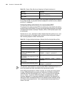
A bout t his g uide this guide describes 3com routers and how to configure them. Conventions table 1 and table 2 list conventions that are used throughout this guide. Table 1 notice icons table 2 text conventions icon notice type description information note information that describes important feat...
Page 6
2 a bout t his g uide.
Page 7: Etting
I g etting s tarted chapter 1 3com router introduction chapter 2 3com router user interface.
Page 8
4.
Page 9: Outer
1 3c om r outer i ntroduction this chapter includes information on the following topics: ■ overview of the 3com router system ■ architecture of the 3com router ■ features of the 3com router version 1.10 ■ new features of the 3com router 1.X overview of the 3com router system the 3com router os is th...
Page 10
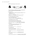
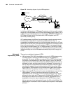
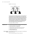
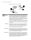
6 c hapter 1: 3c om r outer i ntroduction figure 1 schematic diagram of the 3com router architecture features of the 3com router version 1.10 the following table lists the basic features of the 3com router 1.X: table 3 list of the 3com router 1.X features system service tcp/udp ip forwarding engine ...
Page 11
Features of the 3com router version 1.10 7 network protocol ip service ■ supports arp ■ supports static domain name resolution ■ supports ip address unnumbered ■ supports dhcp server and dhcp relay ■ supports vlan ■ supports ip accounting non-ip service ■ supports novell ipx protocol, provide rip an...
Page 12
8 c hapter 1: 3c om r outer i ntroduction network security authentication, authorization and accounting (aaa) service ■ provides ppp and login user authentication ■ supports radius, provides radius authentication/accounting ■ provides local authentication ■ supports chap and pap authentication firew...
Page 13
Features of the 3com router version 1.10 9 quality of service (qos) traffic classification and flow control ■ supports car (committed access speed) and packet priority, monitoring the network traffic entering isp ■ supports lr (line rate of physical interface) to limit the total speed of packet tran...
Page 14
10 c hapter 1: 3c om r outer i ntroduction new features of the 3com router 1.X new features have been added to the 3com router1.10. Support new interfaces e3 and ce3 interfaces both e3 and e1 are part of the itu-t digital carrier architecture and are used in most regions beyond north america. The da...
Page 15
New features of the 3com router 1.X 11 ■ combined with bdr, frame relay over isdn can be taken as the backup communication method for frame relay. Multilink frame relay the multilink frame relay (mfr) feature introduces functionality based on the frame relay forum multilink frame relay uni/nni imple...
Page 16
12 c hapter 1: 3c om r outer i ntroduction.
Page 17: Outer
2 3c om r outer u ser i nterface this chapter includes information on the following topics: ■ establish configuration environment ■ command line interface (cli) ■ user identity management ■ basic configuration and management of the system establish configuration environment the 3com router 1.X suppo...
Page 18
14 c hapter 2: 3c om r outer u ser i nterface figure 3 establish a new connection figure 4 select the computer serial port for actual connection.
Page 19
Establish configuration environment 15 figure 5 set port communication parameters figure 6 select terminal emulation type 3 power on the router to display the self-test information of the router. Press enter after the self-test to display the prompt “username:” and “password:”. Type in the correct u...
Page 20
16 c hapter 2: 3c om r outer u ser i nterface 4 enter the command to configure the router or view the running status of the router. Enter “?” to get help when necessary. For details of specific commands, please refer to the following chapters. Remote configuration environment via async serial port t...
Page 21
Establish configuration environment 17 figure 8 establish a dial-up connection via “hyperterminal” figure 9 dial on remote computer 4 if a dial-up connection is established, then press enter after the self-test to display the prompt “username:” and “password:”. Enter the correct username and the pas...
Page 22
18 c hapter 2: 3c om r outer u ser i nterface configuration environment, connect the computer with the router via the wan interface. Figure 10 . Establish configuration environment of local telnet connection figure 11 establish a configuration environment of a remote telnet connection 2 as shown in ...
Page 23
Command line interface (cli) 19 figure 12 run a telnet program figure 13 establish a telnet connection with router the host name in the above figure is the name or ip address of a router interface of the remote connection. 3 if connection is established, press enter after the self-test to display th...
Page 24
20 c hapter 2: 3c om r outer u ser i nterface ■ provide online help any time the user keys in “?”. ■ provide network test commands, such as tracert and ping , etc. To quickly diagnose whether the network is normal. ■ provide rich and detailed debugging information for diagnosis of network faults. ■ ...
Page 25
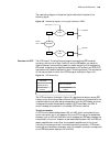
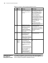
Command line interface (cli) 21 figure 14 hierarchical view structure of the 3com router the following table gives some details of the functionality features of the command views as well as the commands for entering these views. System view table 4 views and their prompts system view rip view ospf v...
Page 26
22 c hapter 2: 3c om r outer u ser i nterface async serial interface view configures the asynchronous serial interface parameters [router-async0] enter interface async 0 in any views enter quit to return to the system view aux interface view configures the aux interface parameters [router-aux0] ente...
Page 27
Command line interface (cli) 23 the command line prompt character consists of the network device name (router by default) and the command view name, such as [router-rip]. The commands are divided according to view. In general, in a certain view, only the commands defined by the view can be executed,...
Page 28
24 c hapter 2: 3c om r outer u ser i nterface ■ the help information obtained via the above-mentioned online help is described as follows: 1 full help: enter “?” in any view, all the commands in this view and their brief descriptions can be obtained. [router]? Aaa-enable enable aaa(authentication, a...
Page 29
Command line interface (cli) 25 history command the command line interface of the 3com router 1.X provides a function similar to doskey by automatically saving the history of commands inputted users. Users can check the history of commands saved in the command line to repeat execution. 10 history co...
Page 30
26 c hapter 2: 3c om r outer u ser i nterface table 9 display function table user identity management the 3com router sets three kinds of router management users: administrator user, operator user and guest user. Different kinds of users have different rights to execute commands. 1 an administrator ...
Page 31
User identity management 27 by default, no user is set on the router. In this case, the user can log onto the router without username and password, operating as the administrator user and have the right to execute all commands. The router should be configured with at least one administrator user. Th...
Page 32
28 c hapter 2: 3c om r outer u ser i nterface by default, the system clock is 08:00:00 1 1 1997. The system clock will reset to the initial number when the configuration is deleted by using the delete command or is deleted at the boot menu. 3 reboot the system please perform the following commands i...
Page 33: Ystem
Ii s ystem m anagement chapter 3 system management chapter 4 terminal service chapter 5 configuring network management chapter 6 display and debugging tools chapter 7 pos terminal access service.
Page 34
30
Page 35: Ystem
3 s ystem m anagement this chapter includes information on the following topics: ■ storage media and file types supported by the system ■ upgrade boot rom software ■ upgrade the 3com router main program software ■ configure on-line upgrading of the card ■ configuration file management ■ configure ft...
Page 36
32 c hapter 3: s ystem m anagement quickly input ctrl+d to enter the boot rom menu. If ctrl+d is not input within three seconds, the system will restart the router and the following prompt information displays: ****************************************** * * * 3com router series bootrom, v4.25 * * * ...
Page 37
Upgrade boot rom software 33 5 example: if you select baud rate 115200 bps, the system will prompt you to modify the baud rate and select xmodem transfer protocol: download speed is 115200 bps. Change the terminal's speed to 115200 bps, and select xmodem protocol. Press enter key when ready. Accordi...
Page 38
34 c hapter 3: s ystem m anagement figure 16 “send file” message window 8 after downloading, the router will save the file into flash or nvram, display the following information, and prompt restoring of the baud-rate setting of the terminal emulator. Download completed. Writing to flash memory... Pl...
Page 39
Upgrade the 3com router main program software 35 you can load the 3com router main software with xmodem or tftp (trivial file transfer protocol) approach when powering on the router. Alternatively, you can load the software with the ftp (file transfer protocol) approach after the router is booted. X...
Page 40
36 c hapter 3: s ystem m anagement 3: 38400 bps 4: 57600 bps 5: 115200 bps 6: exit and reboot enter your choice(1-6): make your selection as needed. 5 after a baud rate (115200 bps for example) is selected, the system displays the following information to prompt you to modify the baud rate and selec...
Page 41
Upgrade the 3com router main program software 37 figure 18 transfer file dialog box 7 click browse to open the folder containing the boot rom software, select the file, change the download protocol to xmodem, click send, and the system will start downloading and the following dialog box displays: fi...
Page 42
38 c hapter 3: s ystem m anagement 9 restore the baud rate of the terminal emulation program to 9600 bps and press enter for rebooting the router so that the new 3com router main program software can be run. Tftp approach tftp is a protocol used for transferring trivial files between clients and ser...
Page 43
Upgrade the 3com router main program software 39 figure 21 tftpd32: set interface enter the file directory in the field of base directory, and click ok for confirmation. The setting interface may vary with different tftp server program software. 2 connect the router a select an ethernet interface fo...
Page 44
40 c hapter 3: s ystem m anagement network interface parameters: do you want a lan interface? [n] y this board's lan ip address? [169.254.1.1] 10.110.10.1 subnet mask for lan (0 for none)? [255.255.0.0] tftp server parameters: ip address of the tftp server? [169.254.75.166] 10.110.10.13 what is the ...
Page 45
Upgrade the 3com router main program software 41 input the boot rom password at the prompt. (by default, no ex-factory boot rom password is set on the router. Simply press enter in this case.) if the boot rom password has been modified, enter the correct password. The system terminates the process i...
Page 46
42 c hapter 3: s ystem m anagement after a client originates a control connection to a server by using the port command and uses a randomly assigned ftp port to establish the control link with port 21 on the server, the link will be in place until there is no data waiting for transmission. The serve...
Page 47
Upgrade the 3com router main program software 43 remote ftp user sends a request to the ftp server, and the server will perform actions accordingly and return the execution result to the subscriber. Perform the following configuration in system view. Table 18 enable ftp server upgrade the 3com route...
Page 48
44 c hapter 3: s ystem m anagement 7 at the prompt ftp> , appearing after the file uploading is completed, enter the dir command to display the file name and size on the router. If the uploading operation is successful, the program or configuration file on the router and the uploaded file on the hos...
Page 49
Configure on-line upgrading of the card 45 configure on-line upgrading of the card the 3com router 1.X supports on-line upgrading of such cards as 2sa/4sa, e1vi and 6am/12am. While upgrading, the host acts as ftp server and the router to be upgraded as the ftp client. The host and the router coordin...
Page 50
46 c hapter 3: s ystem m anagement figure 24 path name dialog box select the check boxes read, write and delete in files and click ok to return. Figure 25 edit users/group check box 4 the cards can be upgraded on-line after the on-line upgrading files are copied to the path of the serv-u ftp. Perfor...
Page 51
Configuration file management 47 after the display version command is used, the information on the slot displays: card name driver need to be updated on-line upgrading uses the upgrading program of other cards and this card will not be upgraded on-line. The console displays the following prompt info...
Page 52
48 c hapter 3: s ystem m anagement table 21 load configuration files follow these steps in the terminal emulation program: 1 enter the command and make the confirmation. [router] download config do you want really download the config.Ini?(y/n)y 2 set the binary transmission protocol to xmodem/crc. C...
Page 53
Configuration file management 49 at the prompt of “ftp>”, use the put localfile [ remotefile ] command to upload the specified file to the router. Remotefile should use the name of the config file on the router, and the name is case sensitive. You can use the ftp-server config-name command to modify...
Page 54
50 c hapter 3: s ystem m anagement 226 file transmit success. Ftp: 735 bytes received in 0.06seconds 12.25kbytes/sec. View current and saved configuration of the router during the power-on of the router, read the configuration files from flash (or nvram) to initialize the router. Therefore, the conf...
Page 55
Configuration file management 51 table 25 select and view the storage media of configuration file if there is only one type of storage media available, the configfile command will not be effective. Modify and save current configuration users can modify the current configuration of the router via the...
Page 56
52 c hapter 3: s ystem m anagement table 28 set/clear the flag bit to enter the initial setup by default, no flag bit for entering the initial setup mode is set. Configure ftp ftp (file transfer protocol), which belongs to the application layer protocol in the tcp/ip protocol suite, mainly provides ...
Page 57
Configure ftp 53 table 29 set the authentication mode of ftp server 2 add ftp authorized user name and password input the following command in system view. Table 30 add ftp authorized user name and password for a detailed introduction to the above command, please refer to the chapter “aaa and radius...
Page 58
54 c hapter 3: s ystem m anagement the names of the program/configuration file are “system” and “config” respectively by default. In the command, file-name is a character string with the length of 1 to 30. 2 set ftp update mode when logging onto the ftp server from a pc, you can use the put command ...
Page 59
Configure ftp 55 display ftp serve r table 36 display ftp server operation command display the configuration status of current ftp server display ftp-server display detailed information of the ftp user display local-user.
Page 60
56 c hapter 3: s ystem m anagement.
Page 61: Erminal
4 t erminal s ervice this chapter includes information on the following topics: ■ terminal service overview ■ terminal message service ■ dumb terminal service ■ terminal service of telnet connection ■ rlogin terminal service ■ x.25 pad remote access service terminal service overview the terminal ser...
Page 62
58 c hapter 4: t erminal s ervice features of terminal service at async serial port the 3com router supports remote configuration on the router via asynchronous serial port (including synchronous/asynchronous serial port, 8/16 asynchronous serial port, and aux port). Please refer to chapter 2 “3com ...
Page 63
Terminal message service 59 with user b, user a should telnet onto router b and execute the send command to send the related information in all views. Then user b can receive the “message” sent from user a. If user b does not want to receive additional similar messages, they can use the send switch ...
Page 64
60 c hapter 4: t erminal s ervice typical example of terminal message service configuration # input the send command in system view. [router] send enter message, end with ctrl/z; abort with ctrl/c: # input the contents of the message that the terminal will send. Hello world # (enter to terminate the...
Page 65
Dumb terminal service 61 by default, no dumb terminal service is configured. 2 configure auto-execute command command if the auto-execute command command is configured on the asynchronous serial interface, when you press enter twice on the external terminal connected to the interface or log onto the...
Page 66
62 c hapter 4: t erminal s ervice figure 27 dumb terminal networking diagram 1 configure the interface to dumb terminal mode. [router-serial1] physical-mode async [router-serial1] undo modem [router-serial1] async mode flow 2 configure the auto-execute command command. [router-serial1] auto-execute ...
Page 67
Terminal service of telnet connection 63 figure 29 telnet client service reverse telnet overview reverse telnet service: the user logs on the router with a specified port number by running the telnet client program on the pc. Then the connection to the serial port device connected with the async por...
Page 68
64 c hapter 4: t erminal s ervice table 46 establish telnet server or telnet client connection by default, telnet server starts automatically. The default value of service-port is 23. To terminate telnet service, enter ctrl+]at telnet client side. Setup reverse telnet connection please use async mod...
Page 69
Terminal service of telnet connection 65 the interface listen port number is within the range of 1025 to 65535. Please note that the listen port number cannot be the same as that of the widely used ports. By default, the port number and asynchronous interface have the following relations: ■ the asyn...
Page 70
66 c hapter 4: t erminal s ervice password: user guest logged in . 3 the message showing successful telnet to router b should pop up and display the host name of routerb. [routerb] example of reverse telnet the host is connected to the router, then communicates with the device connected to the seven...
Page 71
Rlogin terminal service 67 ■ only supports ip address configuration. Dns is not supported. ■ the supported terminal type is vt100. ■ the supported baud rate is 9600 bps. ■ supports remote access of user terminals connected with the asynchronous serial port under the flow mode by asynchronous private...
Page 72
68 c hapter 4: t erminal s ervice sco openserver(tm) release 5 (c) 1976-1998 the santa cruz operation, inc. (c) 1980-1994 microsoft corporation. All rights reserved. For complete copyright credits, enter "copyrights" at the command prompt. You have mail terminal type is vt100 # x.25 pad remote acces...
Page 73
X.25 pad remote access service 69 therefore x.25 pad devices actually serve as a procedure translator or network server, providing services to different terminals and helping them to access the x.25 network. The 3com router implements x.29 and x.3 protocol in the x.25 pad as well as in the x.29 prot...
Page 74
70 c hapter 4: t erminal s ervice by default, no x.25 pad remote user is configured at the server side. For details of the command, refer to the relevant sections on security configuration commands in command reference (v1.6). Start aaa authentication of x.25 remote users after the configuration of ...
Page 75
X.25 pad remote access service 71 exit command can also be nested with the pad command. That is, users can access a third or even more routers from a router by repeatedly using the telnet/pad command or by repeatedly using the exit command to exit the routers being accessed in turns until returning ...
Page 76
72 c hapter 4: t erminal s ervice c enter the view of interface serial 0 and set its link layer protocol as x.25 dte ietf. [routera]interface serial 0 [routera-serial0]link-protocol x25 dte ietf d set its x.121 address as 123456. [routera-serial0]x25 x121-address 123456 2 configure router b: a enter...
Page 77: Onfiguring
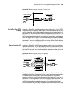
5 c onfiguring n etwork m anagement this chapter includes information on the following topics: ■ snmp overview ■ rmon overview snmp overview simple network management protocol (snmp), a widely accepted industry standard, is the most dominant network management protocol in computer networks by far. I...
Page 78
74 c hapter 5: c onfiguring n etwork m anagement addition to the functions defined in snmpv2c and snmpv1. In other words, snmpv3 develops snmpv2c by adding security and management functions. Snmpv1 and snmpv2c lack security functions, especially in the aspect of authentication and privacy. Snmpv1 de...
Page 79
Snmp overview 75 sub-tree, the network administrator can access the device with read or write authority. Otherwise, the operations will be rejected. Snmp architecture an snmp entity comprises one snmp engine and multiple snmp applications. The snmp engine is the core of the snmp entity. It transceiv...
Page 80
76 c hapter 5: c onfiguring n etwork m anagement table 56 3com router-supported mib configure snmp snmp configuration includes: ■ configure the network management agent on a router ■ configure the information of router administrator ■ configure the snmp version ■ configure the trap ■ adjust the maxi...
Page 81
Snmp overview 77 “corporation code of 3com corporation. (800007db) + equipment information”. Equipment information can be the ip address, mac address or self-defined hexadecimal digit string. You can skip these two operations when you begin to configure snmp for a router because snmp service will be...
Page 82
78 c hapter 5: c onfiguring n etwork m anagement by default, snmpv3 is used. The default view name in the system is viewdefault, and oid of which is 1.3.6.1. Snmp group has only the read-only authority by default. If snmpv1/snmpv2c is used, the community name or snmpv1/snmpv2c groups and users shoul...
Page 83
Snmp overview 79 by default, the router is disabled to send traps. 5 configure the maximum size of snmp packets that the router can send/receive set the max snmp messages that can be received/sent by the agent according to the network loading capacity. Perform the following configurations in system ...
Page 84
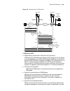
80 c hapter 5: c onfiguring n etwork m anagement typical configuration examples example 1: configure network management of snmpv1 i. Networking requirements in the following diagram the nms and a router are connected via the ethernet. The ip addresses of nms and the ethernet interface on the router ...
Page 85
Rmon overview 81 ■ required if traps are to be sent — the ip address of the interface ethernet 0 is the source address of the traps, and the address of the nms is the destination address. Ii. Networking diagram refer to the networking diagram of example 1. Iii. Configuration procedure 1 enable the r...
Page 86
82 c hapter 5: c onfiguring n etwork m anagement thus managing large-scale interconnection networks easily and effectively. Rmon also allows several monitors and can collect data in two ways: one is to collect with the rmon probe — nms directly obtains management data from an rmon probe and controls...
Page 87
Rmon overview 83 ■ enable rmon statistics of ethernet interface 1 enable rmon statistics of ethernet interface after enabling rmon statistics of an ethernet interface, the router will perform the statistics of the packet incoming and outgoing through this interface. After disabling it, the router wi...
Page 88
84 c hapter 5: c onfiguring n etwork m anagement [routera] interface ethernet 0 [routera-ethernet0] rmon promiscuous.
Page 89: Isplay
6 d isplay and d ebugging t ools this chapter includes information on the following topics: ■ display command set ■ debugging command set ■ test tool of network connection ■ log function display command set with display commands, the system status and system information can be viewed. Display comman...
Page 90
86 c hapter 6: d isplay and d ebugging t ools two switches control the output of the debugging information: ■ debugging switch, which controls whether to test a certain function/module/protocol. ■ syslog output direction switch, which controls outputting the debugging information to the control cons...
Page 91
Test tool of network connection 87 please see relevant chapters in the 3com router command reference guide for detailed meanings of various options and parameters. Ping supporting ip protocol ■ for each ping message sent, if the response message has not been received when the waiting time crosses th...
Page 92
88 c hapter 6: d isplay and d ebugging t ools !!!!! --2.0.0c91.F61f ipx ping statistics-- 5 packets transmitted 5 packets received 0% packet loss round-trip min/avg/max = 1/2/3 ms tracert command (trace route command) the trace route command helps to trace the current network path to a destination. ...
Page 93
Log function 89 3 lilac-dmc.Berkeley.Edu (128.32.216.1) 39 ms 19 ms 19 ms 4 ccngw-ner-cc.Berkeley.Edu (128.32.136.23) 19 ms 39 ms 39 ms 5 ccn-nerif22.Berkeley.Edu (128.32.168.22) 20 ms 39 ms 39 ms 6 128.32.197.4 (128.32.197.4) 59 ms 119 ms 39 ms 7 131.119.2.5 (131.119.2.5) 59 ms 59 ms 39 ms 8 129.14...
Page 94
90 c hapter 6: d isplay and d ebugging t ools set the direction of syslog outputting log information as described before, syslog of the 3com router 1.X can output various log information in four directions: ■ output log information to local control console via console port ■ output log information t...
Page 95
Log function 91 set severity of log information syslog is divided into 8 levels according to the severity (or priority) of the information. The rule to filter the log information according to the level is: the more urgent the log information is, the less severe it will be. The log information with s...
Page 96
92 c hapter 6: d isplay and d ebugging t ools here, module stands for the module name. Only the log information related to a specified module can be filtered and output. Turn on/turn off syslog please enter the following commands in system view. Table 70 turn on/turn off syslog when syslog is turned...
Page 98
94 c hapter 6: d isplay and d ebugging t ools.
Page 99: Pos T
7 pos t erminal a ccess s ervice this chapter contains information on the following topics: ■ pos access service overview ■ pos access service configuration ■ display and debug pos access ■ typical configuration example of pos access service pos access service overview point of sale (pos) service is...
Page 100
96 c hapter 7: pos t erminal a ccess s ervice figure 40 dial-up access when the pos access router is located at the commercial client side due to the way pos access service usually operates, that is, low speed, high frequency and small traffic, it is rather sensitive to the dial-up connection time a...
Page 101
Pos access service configuration 97 ■ avoiding the dial-up time problem and fast connecting to the transaction processing center. ■ reducing the number of occupied communication links, hence saving the communications cost greatly. ■ avoiding the problem of service queuing as it is as though each pos...
Page 102
98 c hapter 7: pos t erminal a ccess s ervice if the fcm interface is used as pos access interface undo modem cannot be configured. If another interface is used as the pos access interface undo modem must be configured. Since pos access does not support flow control, the interface should be configur...
Page 103
Pos access service configuration 99 pos access does not support flow control, therefore, the interface should be configured with the flow-control none command. 5 configure pos multi-application map pos multi-application is a kind of pos access function, which sends the packets from a pos terminal de...
Page 104
100 c hapter 7: pos t erminal a ccess s ervice implemented otherwise, the system will prompt as follows to indicate that the configuration has failed: app-state is wrong . 7 set the parameters of fcm used during modem negotiation in the pos access application, the modem on the fcm card usually acts ...
Page 105
Typical configuration example of pos access service 101 t ypical configuration example of pos access service configuration example when the router is located at the fep side in tcp/ip mode i. Networking requirements three pos terminals access the router a located at the fep side through the fcm card...
Page 106
102 c hapter 7: pos t erminal a ccess s ervice 9 configure pos access interface fcm2 [router] interface fcm2 [router-fcm2] async mode pos 3 configuration example when the router is located at the fep side in asynchronous connection mode i. Networking requirements three pos terminals access the route...
Page 107
Typical configuration example of pos access service 103 [router-fcm2] async mode pos 3 9 configure async 0 to operate in pos application mode. [router] interface async 0 [router-async0] undo modem [router-async0] flow-control none [router-async0] async mode posapp 10 configure async 1 to operate in ...
Page 108
104 c hapter 7: pos t erminal a ccess s ervice [routera] interface async 1 [routera-async1] undo modem [routera-async0] flow-control none [routera-async0] undo detect dsr-dtr [routera-async1] async mode pos 2 f configure pos access interface 2. [routera] interface async 2 [routera-async2] undo modem...
Page 109: III
Iii i nterface chapter 8 interface configuration overview chapter 9 configuring lan interface chapter 10 configuring wan interface chapter 11 configuring logical interface.
Page 110
106.
Page 111: Nterface
8 i nterface c onfiguration o verview this chapter contains information on the following topics: ■ interface configuration overview ■ configure interface ■ display and debug interface interface configuration overview the router interface refers to the part through which the router exchanges data and...
Page 113
Display and debug interface 109 ■ if a firewall is to be established on this interface, please configure parameters about related message filtering or address conversion. There are lots of parameters to be configured in the interface view. So, this part will mainly introduce configurations of some p...
Page 114
110 c hapter 8: i nterface c onfiguration o verview.
Page 115: Onfiguring
9 c onfiguring lan i nterface this chapter contains information on the following topics: ■ ethernet interface overview ■ configure ethernet interface ■ display and debug ethernet interface ■ typical ethernet interface configuration example ■ troubleshooting ethernet interface overview ethernet inter...
Page 116
112 c hapter 9: c onfiguring lan i nterface table 85 enter view of specified ethernet interface 2 set network protocol address the 3com router supports ip and ipx at ethernet interface. Therefore, it is necessary to configure ip or ipx network address. Please use the following commands in ethernet i...
Page 117
Display and debug ethernet interface 113 value ranges and default values of mtus with different link layer protocol are different. When ethernet_ii frame format is adopted, mtu value range will be 46-1500 bytes with the default value as 1500 bytes, and when ethernet_snap frame format is adopted, mtu...
Page 118
114 c hapter 9: c onfiguring lan i nterface typical ethernet interface configuration example i. Networking requirement as shown below, the ethernet interfaces of routers a is connected to ip networks 192.168.0.0. The computer in lan connects to the internet through router a. Set the mtu of ethernet ...
Page 119
Troubleshooting 115 the party with 100 mbps configuration shows no connection, while the party with 10 mbps connection shows the connection has been established. Furthermore, the activity indicator of the physical layer blink quickly and messages can not be received or transmitted normally. On check...
Page 120
116 c hapter 9: c onfiguring lan i nterface hub is connected, all the other devices on the whole network segment will show serious network collisions), while the party working in full duplex mode shows large amount of error messages received, accompanied with serious message losses at both parties. ...
Page 121: Onfiguring
10 c onfiguring wan i nterface this chapter contains information on the following topics: ■ wan interface introduction ■ asynchronous serial interface ■ aux interface ■ synchronous serial interface ■ isdn bri interface ■ ce1/pri interface ■ ct1/pri interface ■ e1-f interface ■ t1-f interface ■ ce3 i...
Page 122
118 c hapter 10: c onfiguring wan i nterface ■ set the asynchronous serial interface to work in dialup or dedicated line mode ■ set link layer protocol ■ set baud rate ■ set link establishment mode ■ set the check mode in flow mode ■ set stop bit in flow mode ■ set data bit in flow mode ■ set flow c...
Page 123
Asynchronous serial interface 119 instructions in dialup mode. In dedicated line mode, ensure that modem command is not configured, i.E. Disable dial with undo modem command. Please use the following commands in the view of asynchronous serial interface. Table 96 set the work mode of asynchronous se...
Page 124
120 c hapter 10: c onfiguring wan i nterface dedicated mode is usually used when asynchronous serial interfaces are directly connected. ■ flow: also called the interactive mode, which means two ends of the link interact with each other after the setup of a physical connection. The calling end sends ...
Page 125
Asynchronous serial interface 121 when the link establishment mode of async serial interface is flow or tty, the two ends of the link will interact with each other after the setup of a physical connection. The calling end will send configuration command to the receiving end and set the interactive p...
Page 126
122 c hapter 10: c onfiguring wan i nterface please use the following commands in the view of the asynchronous serial interface. Table 104 enable or disable the level detection for the asynchronous serial interface by default the level detection is enabled for the asynchronous serial interface. 12 e...
Page 127
Synchronous serial interface 123 configure aux interface 1 enter aux interface view perform the following configuration in the all views. Table 108 enter aux interface view 2 configure aux interface the configuration of aux interface is basically the same with that of common asynchronous serial inte...
Page 128
124 c hapter 10: c onfiguring wan i nterface ■ enable or disable level detection ■ enable or disable data carrier detection ■ setting the synchronous serial interface to work in full duplex or half duplex mode ■ enable or disable internal loopback/external loopback ■ set mtu ■ set the time interval ...
Page 129
Synchronous serial interface 125 perform following commands in synchronous serial interface view. Table 112 set the digital signal encoding format of synchronous serial interface by default, the digital signal encoding format of synchronous serial interface is nrz. 5 set baud rate please use the fol...
Page 130
126 c hapter 10: c onfiguring wan i nterface txclk stands for transmitting clock, rxclk for receiving clock, the clock before “=” is dte-side clock, and that behind “=” is dce-side clock. Please use the following commands in the view of the synchronous serial interface. Table 115 select work clock t...
Page 131
Synchronous serial interface 127 level detection is enabled for the synchronous serial interface by default. 9 enable or disable data carrier detection by default, when the system decides whether the synchronous serial interface is in up status or down status, it detects the dsr signal, dcd signal a...
Page 132
128 c hapter 10: c onfiguring wan i nterface 12 configure mtu mtu of synchronous serial interface affects the fragmentation and reassembling of ip network protocol message on this interface. Please use the following commands in the view of the synchronous serial interface. Table 121 set mtu of synch...
Page 133
Isdn bri interface 129 equipment complying with relevant isdn standard of itu-t able to access isdn easily. User-network interface specification of isdn: in itu-t i.411 recommendations, reference configurations for isdn user-network interfaces are given according to concepts of function group (a gro...
Page 134
130 c hapter 10: c onfiguring wan i nterface ■ whether the interface provided by telecom service provider is isdn bri u interface or isdn bri s/t interface: in itu-t i.411 recommendation, the reference model of isdn user-network interface is given. However, there is a worldwide dispute about the pos...
Page 135
Ce1/pri interface 131 ■ when the interface is used as a ce1 interface, all the timeslots except timeslot 0 can be divided into multiple channel sets at will, and each group can be used as an interface upon timeslot binding. Its logic feature is the same as that of a synchronous serial interface. It ...
Page 136
132 c hapter 10: c onfiguring wan i nterface table 127 enter the synchronous serial interface view the following are to be set: ■ operating parameters of data link layer protocol, such as ppp, frame relay, lapb or x.25. ■ ip address ■ the operating parameters of the standby center need to be set whe...
Page 137
Ce1/pri interface 133 ■ the rules for address translation or packet filtering need to be set if the firewall is to be set up on the interface. For more details, refer to the related sections of this manual. 4 bind an interface to be a pri set perform the following configurations in ce1/pri interface...
Page 138
134 c hapter 10: c onfiguring wan i nterface table 132 set the line code format on the ce1/pri interface by default, the line code format on the ce1/pri interface is hdb3. 6 set line clock when the ce1/pri interface operates as dce, you should choose the internal clock, that is, master clock mode. W...
Page 139
Ct1/pri interface 135 by default, the functions of internal loopback and external loopback are disabled on the ce1/pri interface. Display and debug ce1/pri interface perform the following configurations in all views to display the status and related information of the ce1/pri interface, so as to mon...
Page 140
136 c hapter 10: c onfiguring wan i nterface ■ bind the interface to be a pri set ■ set the length/attenuation of the transmission cable ■ set the line code format ■ set line clock ■ set frame format ■ enable/disable internal loopback/external loopback 1 enter the view for a specified interface in s...
Page 141
Ct1/pri interface 137 ■ the rules for address translation or packet filtering need to be set if the firewall is to be set up on the interface. For more details, refer to the related sections of this manual. 3 bind an interface to be a pri set perform the following configurations in ct1/pri interface...
Page 142
138 c hapter 10: c onfiguring wan i nterface by default, the attenuation of transmission cable that the ct1/pri interface matches is long 0db. 5 set the line code format a ct1/pri interface supports two types of line code formats: ami format and b8zs format. Perform the following configurations in c...
Page 143
E1-f interface 139 by default, the frame format of ct1/pri interface is esf. 8 enable/disable internal loopback/external loopback the interface needs to be set to internal loopback or external loopback when during the test on some special functions. Perform the following configurations in ct1/pri in...
Page 144
140 c hapter 10: c onfiguring wan i nterface supporting the data link layer protocols ppp, hdlc, frame relay, lapb and x.25, as well as the network protocols ip and ipx. When it works in framed mode, however, it is physically divided into 32 time slots numbered in the range of 0 to 31. In these time...
Page 145
E1-f interface 141 perform the following configuration in e1-f interface view. Table 150 set interface rate after binding operation by default, binding operation will be done on all the time slots on e1-f interface. Time slot 0 on e1-f interface is used for synchronization information transmission. ...
Page 146
142 c hapter 10: c onfiguring wan i nterface table 153 set frame format for an e1-f interface by default, the frame format of e1-f interface is no-crc4. 7 enable or disable local loopback/remote loopback an interface should be place in local loopback or remote loopback for some special functionality...
Page 147
T1-f interface 143 t1-f interface t1-f interface is fractional t1 interface, and it is respectively simplified ct1/pri interface. If there is no need to use multiple channel sets or if isdn pri is not necessary in an t1 application, it is too much to use ct1/pri interface. At this time, t1-f interfa...
Page 148
144 c hapter 10: c onfiguring wan i nterface module in slot 2. Hence, the e1-f interface will be numbered serial 0, and the 4sa interfaces will be numbered serial 1 through serial 4, and the t1-f interfaces will be numbered serial 5 and serial 6. 2 set interface rate after binding operation when t1-...
Page 149
T1-f interface 145 if t1-f interface is used as dce, the slave clock should be selected. If it is used as dte, the master clock should be selected. If the t1-f interfaces of two routers are directly connected, they must respectively work in slave and master clock modes. If the t1-f interface of the ...
Page 150
146 c hapter 10: c onfiguring wan i nterface display and debug t1-f interface perform the display command in all views to display the state of t1-f interface and other related information. Table 163 display and debug t1-f interface ce3 interface both e3 and e1 belong to itu-t digital carrier system ...
Page 151
Ce3 interface 147 table 164 enter the view of the specified e3 interface 2 set clock mode of ce3 interface perform the following configuration in ce3 interface view. Table 165 set clock mode of the ce3 interface by default, ce3 interface uses slave clock. The user can also set clock mode for e1 chan...
Page 152
148 c hapter 10: c onfiguring wan i nterface if framing has been enabled on an e1 channel, you can set its frame format. Perform the following configuration in ce3 interface view. Table 170 set e1 frame forma t by default, the frame format of e1 channel is no-crc4. 6 configure operating mode of ce3 ...
Page 153
Ct3 interface 149 display and debug ce3 interface the display and debug operations of ce3 interface include disabling interface and displaying interface information. But you should be careful when using the shutdown command, because disabling an interface will cause the interface to stop working. Pe...
Page 154
150 c hapter 10: c onfiguring wan i nterface ■ set crc of the serial interface depending on the networking requirements, the user perhaps needs to configure the parameters such as ppp, frame relay and ip address for the ct3 interface. For details, refer to the involving chapters. 1 enter the view of...
Page 155
Ct3 interface 151 table 178 set loopback mode of the ct3 interface difference between two types of external loopback of the ct3 interface: frame header overhead should be processed for external payload loopback (payload) while frame is not processed for external remote loopback (remote). By default,...
Page 156
152 c hapter 10: c onfiguring wan i nterface by default, ct3 mode is used. When ct3 interface works in t3 mode, the system will automatically create a serial interface whose number is serial number/0:0 and whose rate is 44.736mbps. The interface has the same logic feature as that of a synchronous se...
Page 157
Ct3 interface 153 table 185 disable and enable ct3 interface the enabling/disabling operation done on the ct3 interface takes effect on ct3 interface, the t1 channels and the serial interfaces formed through binding operation. The enabling/disabling operation done on the t1 interface takes effect on...
Page 158
154 c hapter 10: c onfiguring wan i nterface.
Page 159: Onfiguring
11 c onfiguring l ogical i nterface this chapter contains information on the following topics: ■ logical interface introduction ■ dialer interface ■ loopback interface ■ null interface ■ sub-interface ■ standby center logic channel ■ virtual-template and virtual interface logical interface introduct...
Page 160
156 c hapter 11: c onfiguring l ogical i nterface some applications (such as configuring local peer of sna) requires that a local interface with specified ip address should be configured without affecting physical interface configuration. Furthermore, this address should have a 32-bit mask to reduce...
Page 161
Sub-interface 157 any packet reaching the null interface will be dropped, which provides another method for packet filtering: just sending unnecessary network traffic to null0 interface, so that there is no need to configure acl. For example: use static routing configuration command ip route-static ...
Page 162
158 c hapter 11: c onfiguring l ogical i nterface configure sub-interfaces of ethernet interface 1 create and delete ethernet sub-interfaces please use the following commands in all views. Table 190 create and delete ethernet interface when using the above commands, if corresponding ethernet sub-int...
Page 163
Sub-interface 159 ■ ipx network number which is different from that of the affiliated wan interface, and other ipx working parameters ■ virtual circuit of the sub-interface please see chapters in operation manual - link layer protocol and operation manual - network protocol for details about the abo...
Page 164
160 c hapter 11: c onfiguring l ogical i nterface [router-serial0]link-protocol fr 3 specify dte as its frame relay terminal type [router-serial0]fr interface-type dte 4 create sub-interface serial 0.1 on wan interface serial0 of router a in point-to point mode, and enter its view [router]interface ...
Page 165
Virtual-template and virtual interface 161 dynamically create a virtual interface based on the configuration parameters of the template. Similarly, after multiple ppp links are bound as mp, a virtual interface also needs to be created to exchange data with the opposite end. At this time, select an i...
Page 166
162 c hapter 11: c onfiguring l ogical i nterface 3 create corresponding relation between the virtual-template and related physical interface in vpn application environment, it is necessary to build up corresponding relations between l2tp group and virtual-template. In mp application environment, it...
Page 167: Ink
Iv l ink l ayer p rotocol chapter 12 configuring ppp and mp chapter 13 configuring pppoe client chapter 14 configuring slip chapter 15 configuring isdn protocol chapter 16 configuring lapb and x.25 chapter 17 configuring frame relay chapter 18 configuring hdlc chapter 19 configuring bridge.
Page 168
164.
Page 169: Onfiguring
12 c onfiguring ppp and mp this chapter contains information on the following topics: ■ ppp overview ■ mp overview ■ configure ppp ■ configure mp ■ display and debug ppp ■ typical ppp configuration example ■ typical mp configuration example ■ fault diagnosis and troubleshooting of ppp ppp overview t...
Page 170
166 c hapter 12: c onfiguring ppp and mp the authenticator sends some randomly generated packets to the requester (challenge), and at the same time it sends its configured username to the requester. When the requester receives the challenge, it will look for the user password according to the authen...
Page 171
Mp overview 167 figure 49 diagram of ppp negotiation phases for detailed description of ppp, refer to rfc1661. Mp overview mp protocol (ppp multilink protocol) can bind multiple ppp links, so as to increase bandwidth. Mp protocol can fragment large packets, and then the fragmentation will be sent to...
Page 172
168 c hapter 12: c onfiguring ppp and mp table 194 configure the link layer protocol of the interface to ppp the default link layer protocol of the interface is ppp. 2 configure ppp authentication ppp has two authentication modes: pap mode and chap mode. Chap authentication is more secure. ■ configu...
Page 173
Configure ppp 169 table 197 configure the local authenticates the peer in chap mode b configure the requester of chap authentication perform the following configuration in the interface view, and use the local-user command in the system view. Table 198 configure as the peer authenticates the local i...
Page 175
Configure mp 171 in mp working mode, it is not recommended to use ppp compression. To configure ppp compression negotiation on the virtual interface, ppp compression must be configured on virtual-template interface before the subordinate physical interface can accept the ppp compression negotiation....
Page 176
172 c hapter 12: c onfiguring ppp and mp ■ configure mp protocol parameters 1 create virtual template table 203 create/delete virtual template 2 configure operating parameters of virtual template comparing virtual template interface with general physical interface, users can find that the link layer...
Page 177
Configure mp 173 ■ bind according to username or endpoint here the username refers to the received remote username when ppp link performs pap or chap authentication. Endpoint is the unique mark of a router and refers to the received remote endpoint when performing lcp negotiation. The system can imp...
Page 178
174 c hapter 12: c onfiguring ppp and mp by default, the maximum link number of links that mp channel permits to bind is 16. B configure the maximum number of fragments received by mp channel table 209 configure the maximum number of fragments received by mp channel by default, the maximum number of...
Page 179
Display and debug ppp 175 by default, virtual baud rate is not set on interface. Display and debug ppp please use the display and debugging commands in all views. Table 212 display and debug ppp typical ppp configuration example pap authentication example i. Configuration requirement as shown in fig...
Page 180
176 c hapter 12: c onfiguring ppp and mp ii. Configuration procedure 1 configure router1: a add a user with name router2 and password hello to the local database [router]local-user router2 password simple hello b set local username as router1 [router]interface serial 0 [router-serial0]ppp chap user ...
Page 181
Typical mp configuration example 177 [router]local-user router-c password simple router-c b specify the virtual interface templates for the two users and begin ppp negotiation for the ncp information using this template [router]ppp mp user router-b bind virtual-template 1 [router]ppp mp user router-...
Page 182
178 c hapter 12: c onfiguring ppp and mp [router]interface serial2: 1 [router-serial2:1]ppp mp [router-serial2:1]ppp authentication-mode pap [router-serial2:1]ppp pap local-user router-c password simple router-c fault diagnosis and troubleshooting of ppp fault 1: link always fails to turn to up stat...
Page 183: Onfiguring
13 c onfiguring ppp o e c lient this chapter contains information on the following topics: ■ ppoe overview ■ configure pppoe client ■ display and debug pppoe client ■ typical pppoe configuration example ppoe overview point-to-point protocol over ethernet (pppoe) can be used for connecting ethernet h...
Page 184
180 c hapter 13: c onfiguring ppp o e c lient implement the client dial-up function of pppoe), so the subscribers can access the internet without installing a pppoe client software on pcs. Furthermore, all the pcs on the same lan can share an adsl account. Figure 52 networking for pppoe as shown in ...
Page 185
Configure pppoe client 181 depending on the needs, it is probably required to configure the parameters such as ppp authentication on a dialer interface. The dialer interface configuration will not be covered in this section, however. Please see operation manual - dial-up for reference. 2 configure p...
Page 186
182 c hapter 13: c onfiguring ppp o e c lient regardless of whether a pppoe session is permanent or packet-triggered, executing the undo pppoe-client command will permanently delete the session. Hence, you need to make reconfiguration for establishing a new pppoe session. Display and debug pppoe cli...
Page 187
Typical pppoe configuration example 183 [router-dialer1]ip ppp-negotiate [router-dialer1]ppp pap local-user 3com password cipher 12345 2 configure a pppoe session [router]interface ethernet 1 [router-ethernet1]pppoe-client dial-bundle-number 1 3 configure the lan interface and the default route [rou...
Page 188
184 c hapter 13: c onfiguring ppp o e c lient.
Page 189: Onfiguring
14 c onfiguring slip this chapter contains information on the following topics: ■ slip overview ■ configure slip ■ display and debug slip ■ typical slip configuration example slip overview slip (serial link internet protocol) can transmit data over the asynchronous serial link. Through slip, the use...
Page 190
186 c hapter 14: c onfiguring slip by default, the synchronous/asynchronous serial interface operates in synchronous mode 2 configure the link layer protocol of the interface to slip perform the following task in the asynchronous interface view. Table 218 configure the link layer protocol of the int...
Page 191
Typical slip configuration example 187 iii. Configuration procedure 1 configure router a: a configure dialer rule [router]dialer-rule 1 ip permit b configure the synchronous/asynchronous interface to asynchronous mode [router]interface serial 0 [router-serial0]physical-mode async c configure ip addr...
Page 192
188 c hapter 14: c onfiguring slip [router]ip route-static 0.0.0.0 0.0.0.0 10.110.0.1.
Page 193: Onfiguring
15 c onfiguring isdn p rotocol this chapter contains information on the following topics: ■ isdn overview ■ configure isdn ■ display and debug isdn ■ typical configuration example ■ fault diagnosis and troubleshooting of isdn isdn overview isdn (integrated services digital network), developed from t...
Page 194
190 c hapter 15: c onfiguring isdn p rotocol ■ set the called number or sub-address to be checked in digital incoming call 1 configure isdn signaling type perform the following configurations in either system view or interface view. Table 220 configure type of signaling on isdn interface by default,...
Page 195
Configure isdn 191 when a router originates a call to pbx, it usually contains all called number information in the setup message. However, you can configure the command to determine whether the sending sending-complete information element (scie) should be carried in the setup message. Perform the f...
Page 196
192 c hapter 15: c onfiguring isdn p rotocol configure isdn dov isdn call includes voice call and digital call. Different communication mode makes different calls. In common circumstances, users initiate voice call when making voice communication and initiate digital call when making data transmissi...
Page 197
Typical configuration example 193 typical configuration example interconnect routers for data transmission via isdn pri line i. Networking requirement router a is connected with router b via wan, as shown in the following diagram. Ii. Networking diagram figure 56 networking diagram of isdn protocol ...
Page 198
194 c hapter 15: c onfiguring isdn p rotocol ii. Networking diagram figure 57 networking for isdn dov iii. Configuration procedure 1 configure router a: [router]dialer-rule 1 ip permit [router]interface bri 0 [router-bri0]ip address 100.1.1.1 255.255.255.0 [router-bri0]dialer-group 1 [router-bri0]di...
Page 199: Onfiguring
16 c onfiguring lapb and x.25 this chapter contains information on the following topics: ■ x.25 and lapb protocols overview ■ configure lapb ■ configure x.25 ■ configure x.25 over other protocols ■ display and debug lapb and x.25 ■ typical lapb configuration example ■ typical x.25 configuration exam...
Page 200: Psn
196 c hapter 16: c onfiguring lapb and x.25 figure 58 x.25 network model the x.25 protocol suite maps to the lowest three layers of the osi (open system interconnection) reference model. The following protocols are typically used in x.25 implementations: packet-layer protocol (plp), link access proc...
Page 201
X.25 and lapb protocols overview 197 once a virtual circuit is established between a pair of dtes, it is assigned with a unique virtual circuit number. When one dte is to send a packet to the other, it numbers this packet (with virtual circuit number) and sends it to dce. According to the number on ...
Page 202
198 c hapter 16: c onfiguring lapb and x.25 figure 61 relations among lapb, x.25 and x.25 switching configure lapb lapb configuration includes: ■ configure the link protocol of the interface to lapb ■ configure lapb protocol parameters 1 configure the link layer protocol of the interface to lapb per...
Page 203
Configure x.25 199 n1 value represents the maximum number bits of i frame that dce or dte wants to receive from dte or dce. N2 value represents the maximum number of times that dce or dte tries to successfully send a frame to dte or dce. Table 232 configure lapb n1, n2 by default, n1 is 12032, and n...
Page 204
200 c hapter 16: c onfiguring lapb and x.25 configure x.25 interface the configuration of x.25 interface includes: ■ configure x.121 address ■ configure x.25 working mode ■ configure x.25virtual circuit range ■ configure x.25 modulo ■ configure x.25 default flow control parameter only when configure...
Page 205
Configure x.25 201 x.25 protocol can multiplex multiple virtual connection over a real physical link between dte and dce, also called virtual circuit (vc) or logical channel (lc). X.25 can establish up to 4095 virtual connections numbered from 1 to 4095. The number that can be employed to identify e...
Page 206
202 c hapter 16: c onfiguring lapb and x.25 table 237 set/cancel x.25 virtual circuit range the above shows that each section (except the permanent virtual circuit section) is defined by two parameters: upper limit and lower limit, the value of which ranges between 1 and 4095 (including 1 and 4095)....
Page 207
Configure x.25 203 end-to-end is affected, that is, the efficiency between two sets of communicating dte increases. 5 configure x.25 flow control parameter it is essential to set correct default flow control parameters (window size and packet size) for the operation of the link because x.25 protocol...
Page 208
204 c hapter 16: c onfiguring lapb and x.25 ■ prohibit the restart of x.25 layer 3 it is necessary to configure certain supplementary x.25 parameters in some special network environments. 1 configure the delay of x.25 layer 3 timer x.25 protocol defines a series of timers to facilitate its procedure...
Page 209
Configure x.25 205 of a call that reaches x.25 interface may be inconsistent with x.121 address of the destination interface (because the destination address of this call is modified within the network), still the interface will accept this call. At this time, one or multiple aliases should be speci...
Page 210
206 c hapter 16: c onfiguring lapb and x.25 table 244 configure/cancel the attributes related to the address code block in the call packet or call accept packet 4 configure default upper layer protocol x.25 call request packet includes a cud field (call user data), which shows the upper layer protoc...
Page 211
Configure x.25 207 configure x.25 datagram transmission the configuration of x.25 datagram transmission includes: ■ create the mapping from the protocol address to x.121 address ■ create the permanent virtual circuit in the most frequently used x.25 service, data is transmitted remotely between two ...
Page 212
208 c hapter 16: c onfiguring lapb and x.25 process and it always exists. An address mapping will be created implicitly while a permanent virtual circuit is created. To create/delete a permanent virtual circuit, perform the following tasks in interface view. Table 247 create/delete permanent virtual...
Page 213
Configure x.25 209 table 248 specify/cancel svc maximum idle time by default, the value of svc maximum idle time is 0 minute, which means this svc will not be disconnected for idle times out. 2 configure the maximum number of svcs that are associated with the same address mapping the maximum number ...
Page 214
210 c hapter 16: c onfiguring lapb and x.25 table 250 specify/cancel packet pre-acknowledgement by default, the number of pre-acknowledged packets is 0. 4 configure x.25 user facility x.25 protocol defines various user facility options. The user can choose and configure the facilities. These configu...
Page 215
Configure x.25 211 window-size and packet-size options are also supported in x25 pvc command. However, in x25 pvc command, these two options specify the window size and maximum packet length of the set pvc. If these two options are not selected in the x25 pvc command, the set pvc will choose the def...
Page 216
212 c hapter 16: c onfiguring lapb and x.25 generally, inter-network protocols will need to send some broadcast datagrams for specific purposes. On the broadcasting physical networks (such as ethernet), such requirements are naturally supported. But for non-broadcasting networks like x.25, how to re...
Page 217
Configure x.25 213 configure x.25 sub-interface x.25 sub-interface is a virtual interface with its own protocol address and virtual circuit. Multiple sub-interfaces can be created on a physical interface, so the networks can be interconnected via one physical interface. The sub-interface of x.25 fal...
Page 218
214 c hapter 16: c onfiguring lapb and x.25 figure 64 x.25 switching networking diagram 1 enable or disable x.25 switching in the system view, perform the following task to enable or disable x.25 switching. Table 257 enable or disable x.25 switching add or delete a pvc route table 258 add or delete ...
Page 219
Configure x.25 215 which guarantees no occurrence of link overload when an address is accessed by a large number of subscribers. X.25 load balancing is provided by dces. In order to implement the load balancing in x.25 networks, a group of dte/dce interfaces (synchronous serial interfaces or xot tun...
Page 220
216 c hapter 16: c onfiguring lapb and x.25 figure 65 diagram of x.25 network load balancing as shown in the above figure, server a and server b concurrently provide subscribers with identical services. They are configured as a hunt group named hg1. Server a and server b have the same address of 999...
Page 221
Configure x.25 217 dce equipment in x.25 networks to provide the function of load balancing for dte equipment) then configuration of x.25 load balancing needs to be made on the routers. The main configuration tasks of x.25 load balancing are as follows: ■ start x.25 switching ■ create x.25 hunt grou...
Page 222
218 c hapter 16: c onfiguring lapb and x.25 table 263 add/delete x.25 switching route whose forwarding address is hunt group 5 configure other x.25 switching routes table 264 add/delete other x.25 switching routes configure x.25 over other protocols configure x.25 over tcp (xot) introduction to xot ...
Page 223
Configure x.25 over other protocols 219 protocol provides reliable data transmission link. Because tcp has the mechanism of error redirection and window flow controlling to guarantee the reliability of links, it can be used by x.25. Xot builds a tcp tunnel connection between the two x.25 networks, a...
Page 224
220 c hapter 16: c onfiguring lapb and x.25 table 265 start x.25 switching 1 by default, do not start x.25 switch. 2 configure ip side interface because the xot implements the connection of two x.25 nets through ip net, first you should ensure that the ip net is expedite. For the specific configurat...
Page 225
Configure x.25 over other protocols 221 table 268 configure pvc xot switching 5 configure keepalive and xot-source attributes after the tcp link is established, tcp will not be easily cleared even if the link is disconnected. But after configuring keepalive, the router will send checking packets in ...
Page 226
222 c hapter 16: c onfiguring lapb and x.25 when configuring an annex g dlci, the user must explicitly configure it with the argument dce or dte. In addition, the configurations on the routers of a connection should not be the same. That is, if a router is configured to work as dte, the other router...
Page 227
Display and debug lapb and x.25 223 by default, x.25 template is not applied on dlcis. Display and debug lapb and x.25 in the all views, perform the following tasks to enable real-time monitoring of the current status of lapb and x.25. Table 273 display and debug lapb and x.25 typical lapb configura...
Page 228
224 c hapter 16: c onfiguring lapb and x.25 [router-serial0]lapb module 128 [router-serial0]lapb window-size 127 2 configure router b: a select interface [router]configure [router]interface serial 1 b specify ip address for this interface [router-serial1]ip address 202.38.160.2 255.255.255.0 c confi...
Page 229
Typical x.25 configuration example 225 e specify address mapping to the peer [router-serial0]x25 map ip 202.38.160.2 x121-address 20112452 f as this is a direct connection, the flow control parameters can be increased slightly [router-serial0]x25 packet-size 1024 1024 [router-serial0]x25 window-size...
Page 230
226 c hapter 16: c onfiguring lapb and x.25 ii. Networking diagram figure 69 connect the router to x.25 public packet network iii. Configuration procedure 1 configure router a: a configure interface ip address [router]interface serial 0 [router-serial0]ip address 168.173.24.1 255.255.255.0 b connect...
Page 231
Typical x.25 configuration example 227 [router-serial0]x25 map ip 168.173.24.1 x121-address 30561001 [router-serial0]x25 map ip 168.173.24.2 x121-address 30561002 configure virtual circuit range i. Networking requirement the link layer protocol of router's interface serial0 is x.25l, with the virtua...
Page 232
228 c hapter 16: c onfiguring lapb and x.25 [router-ethernet0]ip address 196.25.231.1 255.255.255.0 [router-ethernet0]interface serial 0[router-serial0]ip address 192.149.13.2 255.255.255.0 [router-serial0]link-protocol x25 [router-serial0]x25 x121-address 1004358902 [router-serial0]x25 vc-range bi-...
Page 233
Typical x.25 configuration example 229 ii. Networking diagram figure 72 diagram of x.25 sub-interface configuration iii. Configuration procedure 1 configure router a: [router]interface serial 0 [router-serial0]link-protocol x25 dte [router-serial0]x25 x121-address 100 [router-serial0]interface seria...
Page 234
230 c hapter 16: c onfiguring lapb and x.25 svc application of xot i. Networking requirement router b and c connect through ethernet interface, and build tcp connection between them. X.25 packets forward through tcp, and configure svc to implement the svc function. Ii. Networking diagram figure 73 s...
Page 235
Typical x.25 configuration example 231 4 configure router c a start x.25 switching [router]x25 switching b configure x.25 local switching [router]x25 switch svc 2 interface serial 0 c configure xot switching [router]x25 switch svc 1 xot 10.1.1.1 d configure ethernet 0 [router]interface ethernet 0 [r...
Page 236
232 c hapter 16: c onfiguring lapb and x.25 [router-serial0]x25 x121-address 2 [router-serial0]x25 x25 vc-range in-channel 10 20 bi-channel 30 1024 [router-serial0]x25 pvc 1 ip 1.1.1.1 x121-address 1 [router-serial0]ip address 1.1.1.2 255.0.0.0 3 configure router b a start x.25 switching [router]x25...
Page 237
Typical x.25 configuration example 233 ii. Networking diagram figure 75 networking diagram of typical configuration of x.25 hunt group iii. Configuration procedure 1 configure routera a configure the link layer protocol of interface serial1 to x.25 and specify it to operate in dce mode. [router]inte...
Page 238
234 c hapter 16: c onfiguring lapb and x.25 [router]interface serial 0 [router-serial0]link-protocol x25 dte [router-serial0]x25 x121-address 8888 the configurations of routerc and routere are identical with the configuration of routerb 3 configure routerd a configure link layer protocol of interfac...
Page 239
Typical x.25 configuration example 235 note that you must configure a virtual ip address and two static routes on interface serial 1 to deceive the router because two lines connected to the same peer exist in router routerc. Thus load balancing can be achieved because router routerc will deem that t...
Page 240
236 c hapter 16: c onfiguring lapb and x.25 [router-serial1]x25 x121-address 3333 [router-serial1]ip address 2.1.1.3 255.255.255.0 [router-serial1]x25 map ip 1.1.1.1 x121-address 1111 [router-serial1]x25 map ip 2.1.1.1 x121-address 1111 [router-serial1]x25 map ip 1.1.1.2 x121-address 2222 [router-se...
Page 241
Typical x.25 configuration example 237 [router-fr-dlci-100]x25-template profile1 [router-fr-dlci-100]quit i map the frame relay address to the destination ip address. [router-serial1]fr map ip 202.38.163.252 100 2 configure routerb: a create an x.25 template. [router]x25 template profile1 b configur...
Page 242
238 c hapter 16: c onfiguring lapb and x.25 ii. Networking diagram figure 78 networking for the svc application of x.25 over frame relay iii. Configuration procedure 1 configure the router router a: a configure the basic x.25 parameters. [router]interface serial 0 [router-serial0]link-protocol x25 d...
Page 243
Typical x.25 configuration example 239 [router]x25 switch svc 1 interface serial 0 g configure x.25 over frame relay switching. [router]x25 switch svc 2 interface serial 1 dlci 100 4 configure the router router c: a enable x.25 switching. [router]x25 switching b configure serial 0 as the x.25 interf...
Page 244
240 c hapter 16: c onfiguring lapb and x.25 [router-serial0]x25 x121-address 1 [router-serial0]x25 vc-range in-channel 10 20 bi-channel 30 1024 [router-serial0]x25 pvc 1 ip 1.1.1.2 x121-address 2 [router-serial0]ip address 1.1.1.1 255.0.0.0 2 configure router d: a configure the basic x.25 parameters...
Page 245
Fault diagnosis and troubleshooting of lapb 241 [router-x25-profile1]x25 vc-range in-channel 10 20 bi-channel 30 1024 [router-x25-profile1]x25 pvc 1 interface serial 0 pvc 1 5 configure serial 1. A configure s1 as the frame relay interface. [router]interface serial 1 [router-serial1]link-protocol fr...
Page 246
242 c hapter 16: c onfiguring lapb and x.25 ■ facility options inhibited by network have been carried. Troubleshooting: if the address is configured incorrectly, change the configuration. For the last two causes, please consult the network management department for correct channel range and permissi...
Page 247
Fault diagnosis and troubleshooting of x.25 243 ■ if receiving the ping packet forwarded from the router at one end, check whether the returning route has been configured in the routing table. In addition, if the destination ip address for returning the packets is different from that configured in t...
Page 248
244 c hapter 16: c onfiguring lapb and x.25.
Page 249: Onfiguring
17 c onfiguring f rame r elay this chapter contains information on the following topics: ■ frame relay protocol overview ■ configure frame relay ■ configure frame relay qos ■ configure frame relay over other protocols ■ display and debug frame relay ■ typical frame relay configuration example ■ faul...
Page 250
246 c hapter 17: c onfiguring f rame r elay virtual circuits can be divided into permanent virtual circuit and switching virtual circuit, according to their different configuration method. Virtual circuits configured manually are called permanent virtual circuits (pvcs), and those created by protoco...
Page 251
Configure frame relay 247 note the following: ■ the interface's link layer protocol can be configured to frame relay only when it operates in the synchronous mode. ■ when the interface's link layer protocol is slip, the physical attributes of the interface cannot be modified to synchronous mode. At ...
Page 252
248 c hapter 17: c onfiguring f rame r elay when the frame relay interface type is dce or nni, the default type of lmi protocol of interface is q933a. When the frame relay interface type is dte, the default lmi protocol of interface is null. 4 configure the related parameters of frame relay lmi prot...
Page 253
Configure frame relay 249 the following table describes the value ranges and default values of related parameters of the frame relay lmi protocol table 278 descriptions of related parameters of frame relay lmi protocol in which, the related parameters at the dte side include: ■ t391dte: the interval...
Page 254
250 c hapter 17: c onfiguring f rame r elay n392, the dte equipment will assume that the number of errors reaches the threshold, and will regard the physical path and all the virtual circuits as unusable. The parameters at the dce side include: ■ t392dce: define the longest duration for the dce equi...
Page 255
Configure frame relay 251 the map created through the dynamic inverse arp has broadcast attribute. 6 configure frame relay local virtual circuit number perform the following configurations in synchronous serial interface view. Table 281 configure frame relay local virtual circuit number after enteri...
Page 256
252 c hapter 17: c onfiguring f rame r elay b configure virtual circuit of frame relay sub-interface in interface view, perform the following task to configure the virtual circuit of frame relay sub-interface. Table 283 configure virtual circuit of frame relay sub-interface c configure sub-interface...
Page 257
Configure frame relay 253 perform “enabling/disabling frame relay pvc switching” in system view, and configure all the other commands in synchronous serial interface view. Table 286 configure the frame relay pvc switching by default, frame relay pvc switching is disabled. The configured pvc can take...
Page 258
254 c hapter 17: c onfiguring f rame r elay by default, no frame relay switched pvc is created. After configuring the frame relay switched pvc, the user will enter the frame relay switch view to perform the operations of shutdown and undo shutdown on the switched pvc. The differences between configu...
Page 259
Configure frame relay 255 will not take effect. On the mfr interface, you can configure the network layer parameters (e.G., ip address) and frame relay parameters (e.G., dlci). The physical interface bundled on the mfr interface will use the parameters on the mfr interface. Configure mfr the configu...
Page 260
256 c hapter 17: c onfiguring f rame r elay table 294 configure the parameters of the bundle link interface the default link identification is the name of its physical interface. By default, a bundle link will send out hello message every 10 seconds; it will send a hello message a maximum of 3 times...
Page 261
Configure frame relay 257 perform the following configurations in interface view. Table 296 configure frame relay compression on multipoint interface by default, frame relay payload compression is disable. On the 3com router, both the frame relay main interfaces and sub-interfaces can be multipoint ...
Page 262
258 c hapter 17: c onfiguring f rame r elay configure frame relay qos quality of service (qos) is a set of technologies adopted to meet the users' requirements in throughput, delay jitter, delay and packet loss ratio. Briefly speaking, qos technologies provides network services of different qualitie...
Page 263
Configure frame relay qos 259 figure 82 frame relay traffic shaping if the frame relay traffic shaping is applied on the outgoing interface serial 0 on router b, the interface will be able to transmit packets at 64 kbps, a relatively average rate, so as to avoid the network congestion. Even if the c...
Page 264
260 c hapter 17: c onfiguring f rame r elay notification (becn) flag bit is 1, indicating that the congestion has occurred to the network, and the transmit rate of the pvc will be lowered to cir. Frame relay queueing management to ensure that the packets on the pvcs can be transmitted at an average ...
Page 265
Configure frame relay qos 261 figure 85 frame relay traffic policing as shown in the above figure, router a at the user side transmits packets at 192 kbps to router b at the switching side. However, router b only wants to provide the 64 kbps bandwidth for router a. In this case, you need to configur...
Page 266
262 c hapter 17: c onfiguring f rame r elay frame relay congestion management frame relay congestion management can process the frame relay packets whenever there is network congestion. It will discard the packets that are marked with the de flag bit. At the same time, it will notify other devices o...
Page 267
Configure frame relay qos 263 table 299 create/delete a frame relay class by default, no frame relay class is created. After creating the frame relay class using this command, the user will enter the frame relay class view under which you can configure the parameters like cir. 2 associate the frame ...
Page 268
264 c hapter 17: c onfiguring f rame r elay ■ configure the parameters of frame relay class 1 enable the frame relay traffic shaping perform the following configurations in synchronous serial interface view. Table 301 enable/disable the frame relay traffic shaping by default, the frame relay traffic...
Page 269
Configure frame relay qos 265 numerically, the value of cbs should not be less than cir allow, otherwise, the large packets may not be sent. Configure frame relay traffic policing frame relay traffic policing configuration includes: ■ enable the frame relay traffic policing ■ create a frame relay cl...
Page 270
266 c hapter 17: c onfiguring f rame r elay configure frame relay congestion management there are two ways to set the congestion threshold. One is to configure the congestion threshold for a pvc in a specified frame relay class, another is to configure the congestion threshold for the overall interf...
Page 271
Configure frame relay qos 267 configure frame relay de rule list 1 configure a de rule list perform the following configurations in system view. Table 307 configure a de rule list by default, no de rule list is defined. A router can support up to 10 de rule lists, and each of them can contain up to ...
Page 272
268 c hapter 17: c onfiguring f rame r elay by default, the queue type of a frame relay pvc is fifo. When the congestion management is enabled on frame relay pvcs, the queue type on the interface can only be fifo. For the configuration of pq, cq and wfq, refer to the part of qos. 2 configure frame r...
Page 273
Configure frame relay over other protocols 269 configure frame relay over other protocols frame relay over ip ip networks are used to carry the frame relay data to interconnect the frame relay networks. In the technique of frame relay over ip, a gre tunnel is established between the frame relay netw...
Page 274
270 c hapter 17: c onfiguring f rame r elay after configuring the frame relay route through the fr dlci-switch interface tunnel command, two routes will be added to the frame relay routing table on the router. One route takes the tunnel interface as the incoming interface and the serial interface as...
Page 275
Configure frame relay over other protocols 271 ■ the dce device identifies the calling number of the incoming call and authenticates the dte device according to it to determine whether to accept or deny the call. ■ if the dte device passes the authentication, it can establish a b channel to the dce ...
Page 276
272 c hapter 17: c onfiguring f rame r elay a dce device provides frame relay switching. Its one end is connected to a dte device via isdn, and the other end is directly connected to another dte device, as shown in the following figure: figure 91 frame relay switching connection between dte devices ...
Page 277
Configure frame relay over other protocols 273 2 configuration related to frame relay switching only some simple frame relay switching configurations are covered in this section. For other configurations, refer to the link layer protocol. Configure the commands fr switch and fr switching in system v...
Page 278
274 c hapter 17: c onfiguring f rame r elay in the legacy bdr implementation of frame relay over isdn, a dialer interface and all the isdn physical interfaces (including bri and pri interfaces) attached to it will be configured with frame relay. ■ adopt dialer profiles in the dialer profiles impleme...
Page 279
Display and debug frame relay 275 display frame relay data receiving/sending statistics information. Display fr statistics [ interface type number ] display the frame relay pvc statistics display fr pvc-info [ serial number ] [ dlci dlci-number ] display frame relay pvc route table display fr dlci-s...
Page 280
276 c hapter 17: c onfiguring f rame r elay t ypical frame relay configuration example interconnect lans via frame relay network i. Networking requirement interconnect lans via the public frame relay network. The router work as user equipment in the frame relay dte mode. The routers use static addre...
Page 281
Typical frame relay configuration example 277 [router-serial1] ip address 202.38.163.253 255.255.255.0 b configure the link layer protocol of the interface to frame relay [router-serial1]link-protocol fr [router-serial1]fr interface-type dte c configure static address mapping [router-serial1]fr map ...
Page 282
278 c hapter 17: c onfiguring f rame r elay ii. Networking diagram figure 94 mfr bundle networking iii. Configuration procedure 1 configure routera a create a mfr interface. [router]interface mfr 0 [router-mfr0]ip address 202.38.163.251 255.255.255.0 [router-mfr0]fr interface-type dte [router-mfr0]f...
Page 283
Typical frame relay configuration example 279 ii. Networking diagram figure 95 networking diagram of frame relay over ip iii. Configuration procedure 1 configure router a [router]interface serial 0 [router-serial0]ip address 202.38.163.251 255.255.255.0 [router-serial0]fr interface-type dte [router-...
Page 284
280 c hapter 17: c onfiguring f rame r elay [router-fr-class-frts]cir allow 64000 64000 [router-fr-class-frts]cbs 64000 [router-fr-class-frts]cir 64000 [router-fr-class-frts]fragment 80 data-level configuration example of frame relay traffic shaping i. Configuration requirements the router is connec...
Page 285
Typical frame relay configuration example 281 ii. Networking diagram figure 98 networking diagram of frame relay over ip iii. Configuration procedure 1 configure routera a configure the frame relay interface serial0 [router]interface serial 0 [router-serial0]link-protocol fr [router-serial0]fr inter...
Page 286
282 c hapter 17: c onfiguring f rame r elay on routera, two bri interfaces, bri0 and bri1, are available. Bri0 is assigned with the isdn number 660218, the ip address 110.0.0.1 and the dlci number 100. Bri1 is assigned with the isdn number 660208, the ip address 120.0.0.1 and the dlci number 200. On...
Page 287
Typical frame relay configuration example 283 [router-serial2:15]dialer bundle-member 20 for configuring the bdr and frame relay parameters on dialer1, refer to the configuration on dialer0. The user only needs to change the ip address to 120.0.0.2, dlci number to 200, and configure to receive the i...
Page 288
284 c hapter 17: c onfiguring f rame r elay 2 configure routerb a configure the bdr and frame relay parameters on the pri interface. [router]dialer-rule 1 ip permit [router]fr switching [router]controller e1 0 [router-e1-0]pri-set [router]interface dialer 0 [router-dialer0]ip address 110.0.0.2 255.2...
Page 289
Fault diagnosis and troubleshooting of frame relay 285 fault diagnosis and troubleshooting of frame relay fault 1: the physical layer in down status. Troubleshooting: ■ check whether the physical line is normal. ■ check whether the opposite equipment runs normally. Fault 2: the physical layer is alr...
Page 290
286 c hapter 17: c onfiguring f rame r elay ■ check whether the frame relay configurations at both ends are correct. Read the section of troubleshooting in link layer protocol..
Page 291: Onfiguring
18 c onfiguring hdlc this chapter contains information on the following topics: ■ configure hdlc ■ display and debug hdlc configure hdlc hdlc (high data link control) is a bit-oriented link layer protocol. Its most prominent feature is that it can transparently transmit any kind of bit flow without ...
Page 292
288 c hapter 18: c onfiguring hdlc enable hdlc packet debugging debugging hdlc packet [ interface type number ].
Page 293: Onfiguring
19 c onfiguring b ridge this chapter contains information on the following topics: ■ bridge overview ■ configure bridge’s routing function ■ display and debug bridge ■ typical bridge configuration bridge overview bridge is a type of network device on the data link layer, which interconnects local ar...
Page 294
290 c hapter 19: c onfiguring b ridge ■ supports bridging on the frame relay links. ■ supports bridging on the sub-interfaces of vlan. ■ supports bridging on bdr and dialing standby. ■ supports binding of multiple ports and load sharing. ■ support both routing and bridging function for specified pro...
Page 295
Bridge overview 291 figure 102 bridge learns that workstation a is connected with port 1 once workstation b responds to workstation a, the bridge can detect the responding ethernet frame from workstation b and learn that workstation b is also connected to bridge port 1 because the frame is detected ...
Page 296
292 c hapter 19: c onfiguring b ridge figure 104 final bridging address table forward and filter the bridge will make the decision to forward frames or not (that is, to filter frames) depending on the following three conditions: ■ if workstation a sends an ethernet frame whose destination is worksta...
Page 297
Bridge overview 293 figure 106 filter (not forward) ■ suppose that workstation a sends an ethernet frame to workstation c, and the bridge does not find the correlation between the mac address of workstation c and the port in the bridging address table, what will the bridge do? The bridge will forwar...
Page 298
294 c hapter 19: c onfiguring b ridge figure 108 preliminary examination state of bridging loops as shown in the following figure, the broadcast frame is forwarded over ethernet segment 2 and ethernet segment 3 that are connected with bridge z. Upon detecting two copies of this frame on two differen...
Page 299
Bridge overview 295 will also specify which bridge to be the “root bridge” and which bridges to be the “leaf nodes”. A bpdu contains the following information: ■ root identifier: consists of the bridge priority and the mac address of the root bridge. ■ root path cost: path cost from the individual l...
Page 300
296 c hapter 19: c onfiguring b ridge figure 110 spanning tree topology bpdu forwarding mechanism upon the initiation of the network, all the bridges assume themselves as the root bridge. The designated interface of the bridge regularly sends its bpdu once a hello time. If it is the root port receiv...
Page 301
Configure bridge’s routing function 297 will be routed through ip. Certainly, if ip cannot find a route, it will discard the packet instead of forwarding it to the bridge for processing. If the packet uses a protocol other than ip (for example, if it is the packet from the network like appletalk or ...
Page 302
298 c hapter 19: c onfiguring b ridge 2 configure bridge-set each bridge set is independent, and packets can not be transmitted between the ports belonging to different bridge sets. That is, the packets received via one bridge set port can only be sent via the ports of the same bridge set. One physi...
Page 303
Configure bridge’s routing function 299 perform the following configuration in system view. Table 324 enable/disable forwarding by using dynamic address table by default, the dynamic address table is used to forward frames. C configure the aging time of dynamic address table the aging time of dynami...
Page 304
300 c hapter 19: c onfiguring b ridge table 327 configure the bridge priority by default, the bridge priority is 32768. It is valued in the range of 0 to 65535. C configure the path cost of bridge port the path cost of the port is related to its link speed. The higher the link speed is, the lower th...
Page 305
Configure bridge’s routing function 301 table 330 configure the interval for sending bpdus by default, the value of hello time timer is 2 seconds. It is in the range of 1 to 10 seconds. When configuring the hello time timer, it should be noted that: ■ in the spanning tree, all the bridges use the ti...
Page 306
302 c hapter 19: c onfiguring b ridge the max age is the parameter used to judge whether the bpdus are “timeout”. Users can configure it according to the actual network conditions. When a port enables the stp, the max age timer begins to time. If no bpdu is received in the specified period, it will ...
Page 307
Configure bridge’s routing function 303 when creating an acl based on ethernet type code (ethernet-ii, snap or lsap), you can specify aclt-number in the range of 200 to 299. Type-code is a 16-bit hexadecimal number written with a leading “0x”, corresponding to the type-code field in the ethernet-ii ...
Page 308
304 c hapter 19: c onfiguring b ridge by default, no acl is applied on the port. When applying an acl on the port, note that: ■ add the port to a bridge-set first, then apply the acl on that port. ■ if acls of the same type are applied to the same port, the latest acl applied will replace the previo...
Page 309
Configure bridge’s routing function 305 table 340 configure bridge set to route or bridge the network layer protoco l by default, the bridging is enabled, the routing is disabled. You can execute the display bridge bridge-set bridge-template command to view the configuration of routing and bridging ...
Page 310
306 c hapter 19: c onfiguring b ridge table 343 map the bridge address to dlc i 11 configure bridging over bdr perform the following configuration in system view. A define a dialer list table 344 define a dialer list b configure the bridge interface perform the following configuration in interface v...
Page 311
Display and debug bridge 307 table 349 configure bridge on vlan display and debug bridge perform the reset , display and debugging commands in all views. Table 350 display and debug bridge typical bridge configuration transparent bridging multiple lans i. Networking requirements suppose that there a...
Page 312
308 c hapter 19: c onfiguring b ridge ii. Networking diagram figure 111 networking of building transparent bridges between multiple ethernet segments iii. Configuration procedure 1 configure router a [router]bridge enable [router]bridge 1 stp ieee [router]bridge 1 learning [router]bridge aging-time ...
Page 313
Typical bridge configuration 309 transparent bridging over frame relay i. Networking requirements two routers are directly connected via serial interfaces. Implement transparent bridging over the frame relay. Ii. Networking diagram figure 112 transparent bridge over the frame relay iii. Configuratio...
Page 314
310 c hapter 19: c onfiguring b ridge transparent bridging for synchronous dial-in standby i. Networking requirements configure transparent bridging for synchronous dial-in standby on two routers. Thereby, transparent bridging can be implemented by enabling synchronous dial-in in case that the seria...
Page 315
Typical bridge configuration 311 transparent bridging for asynchronous dial-in standby i. Networking requirements configure transparent bridging for asynchronous dial-in standby on two routers. Thereby, transparent bridging can be implemented by enabling asynchronous dial-in in case that the serial ...
Page 316
312 c hapter 19: c onfiguring b ridge bridge-template interface i. Networking requirements configure a router so that routing can be carried out on each interface in the bridge-set. Ii. Networking diagram figure 114 networking of bridge-template interface iii. Configuration procedure [router]bridge ...
Page 317
Typical bridge configuration 313 bridging on sub-interfaces i. Networking requirements two routers are connected via a network cable. Enabling bridging on the ethernet sub-interfaces so that the two bridges established via the routers can be interconnected. Ii. Networking diagram figure 115 networki...
Page 318
314 c hapter 19: c onfiguring b ridge link-set configuration i. Networking requirements bind multiple parallel links between bridges into a link-set so that the links can share the load when bridging the traffic. Ii. Networking diagram figure 116 networking of use link-set to implement port binding ...
Page 319: Etwork
V n etwork p rotocol chapter 20 configuring ip address chapter 21 configuring ip application chapter 22 configuring ip performance chapter 23 configuring ip count chapter 24 configuring ipx chapter 25 configuring dlsw.
Page 320
316.
Page 321: Onfiguring
20 c onfiguring ip a ddress this chapter contains information on the following topics: ■ ip address overview ■ troubleshooting ip address configuration ■ map between wan interface ip address and link layer protocol address ip address overview ip address is a unique 32-bit address assigned to a host ...
Page 322
318 c hapter 20: c onfiguring ip a ddress the ip addresses a user can use are listed in the following table. Table 351 ip address classes and ranges important features of ip address: some ip addresses are not in a hierarchical structure, which is different from the structure of telephone number. In ...
Page 323
Ip address overview 319 completely internal to the enterprise itself, and seen from the outside, the enterprise only has one net-id. When an external message enters this enterprise network, the internal router can route according to the sub-net number, and finally reach the destination host. The fol...
Page 324
320 c hapter 20: c onfiguring ip a ddress figure 119 relation between host name, ip address and physical address configure ip address configure ip address for an interface use a mask to label the network id contained in an ip address. Example: the ip address of an ethernet interface of a router is 1...
Page 325
Ip address overview 321 when configuring the master ip address for an interface, note: ■ an interface can only have one master ip address. ■ when deleting the ip address of the interface, if no ip address and mask is specified, all the ip addresses (including all slave ip addresses) will be deleted ...
Page 326
322 c hapter 20: c onfiguring ip a ddress table 354 set negotiable attribute of ip address for an interface by default, the interface has no negotiating ip address. Note the following: ■ because ppp supports ip address negotiation, ip address negotiation of an interface can be set only when the inte...
Page 327
Ip address overview 323 table 355 configure ip address unnumbered by default, the interface has no ip address. 2 display ip address unnumbered table 356 display ip address unnumbered configuration example i. Configuration requirements suppose the headquarters of a company is in beijing, with subsidi...
Page 328
324 c hapter 20: c onfiguring ip a ddress 2 configure router r1 of shenzhen subsidiary: [router-ethernet0] ip address 172.16.20.1 255.255.255.0 a borrow ip address of ethernet [router-serial0] ip address unnumbered ethernet0 [router-serial0] link-protocol ppp b configure routing to ethernet segment ...
Page 329
Map between wan interface ip address and link layer protocol address 325 cannot receive the arp message, then possibly the error is on the ethernet physical layer. Fault 2: when the interface is encapsulated with ppp or frame relay, the link layer protocol status does not change to up. Troubleshooti...
Page 330
326 c hapter 20: c onfiguring ip a ddress.
Page 331: Onfiguring
21 c onfiguring ip a pplication this chapter contains information on the following topics: ■ configure address resolution protocol (arp) ■ configure domain name resolution (dns) ■ vlan configuration ■ dhcp server configuration ■ configure dhcp relay ■ configure network address translation (nat) conf...
Page 332
328 c hapter 21: c onfiguring ip a pplication by default, the system executes static arp mapping. Static arp mapping items are valid as long as the router works normally, but dynamic arp mapping items are valid for only 20 minutes. Display and debug arp table 359 display and debug arp configure doma...
Page 333
Vlan configuration 329 by default, the system has no static domain name resolution mapping. Pay attention that when adding a domain name mapping, if the same hostname has been input twice, the current configuration will overwrite the previous one. A static domain name resolution table can maintain a...
Page 334
330 c hapter 21: c onfiguring ip a pplication figure 122 format of vlan tag tpid (tag protocol identifier) field has two bytes. When its value is 0x8100, it means the ethernet frame header contains vlan tag. The third and fourth byte are tci (tag control information) fields, with the higher three bi...
Page 335
Vlan configuration 331 in as ethernet interface is connected with a lan switch port. As the ethernet subinterface of every specified vlan id can act as an independent gateway, this subinterface and other ethernet subinterface in the same vlan id should belong to the same subnet segment. Please imple...
Page 336
332 c hapter 21: c onfiguring ip a pplication [router] interface ethernet 0.1 b specify 3 as the id number of the vlan on which the subinterface is located. [router-ethernet0.1] vlan-type dot1q vid 3 c configure ip address for the subinterface. [router-ethernet0.1] ip address 3.3.3.8 255.255.255.224...
Page 337
Dhcp server configuration 333 connected with pc must be set as “untagged” for the reason that pc cannot identify data packet marked with vlan tag. Fault: ping two pcs, but fails to ping them through. Troubleshooting: the steps below can be taken. ■ first, ping the ip address of ethernet subinterface...
Page 338
334 c hapter 21: c onfiguring ip a pplication dhcp server can provide three types of ip address allocation policies according to the different requirements: ■ allocate addresses manually: administrators configure special ip addresses for a small number of particular hosts such as the service server ...
Page 339
Dhcp server configuration 335 ■ dhcp client logins the network for the first time if it is the first time for a dhcp client to login to the network, it will establish a connection with the dhcp server through four stages: ■ discovering stage. This is the stage when the dhcp client searches the dhcp ...
Page 340
336 c hapter 21: c onfiguring ip a pplication will take back the ip address. If the dhcp client wants to continue to use this address, it should renew the ip leasing contract such as extending the leasing contract of the ip address. ■ in practice, the dhcp client will automatically send the message ...
Page 341
Dhcp server configuration 337 ■ configure the range of a dhcp address pool ■ configure the ip addresses that do not participate in auto-allocation in the dhcp address pool ■ configure the lease valid period of the ip addresses in a dhcp address pool ■ configure the ip address of the outgoing gateway...
Page 342
338 c hapter 21: c onfiguring ip a pplication by default, no dhcp address pool is created. 3 configure the range of a dhcp address pool a configure the static binding address allocated to the client some special clients (e.G., www server) need to be bound with fixed ip addresses, that is, to bind a ...
Page 343
Dhcp server configuration 339 the command network cannot be superimposed, that is, the latest configuration will overwrite the previous one. The command network and the commands static-bind ip-address and static-bind mac-address are conflicting. In other words, for the same dhcp address pool, config...
Page 344
340 c hapter 21: c onfiguring ip a pplication by default, the valid leasing period of ip address is 1 day. 6 configure the ip address of egress gateway router for dhcp clients when a dhcp client accesses a server (or host) beyond the local subnetwork, all the data must be sent and received via the e...
Page 345
Dhcp server configuration 341 that is because the new dns address will replace the previous one rather than superimpose it. 9 configure ip address of netbios server used by dhcp clients clients can communicate through the netbios protocol. As for the clients installed with the microsoft operating sy...
Page 346
342 c hapter 21: c onfiguring ip a pplication assume that the ip address in this segment is not in use. Only when it is not in use can the ip address be allocated to the specified client. Perform the following configurations in system view. Table 377 configure maximum number of ping packets sent by ...
Page 347
Dhcp server configuration 343 typical dhcp server configuration example the common dhcp networking methods can be classified into two categories: one is that the dhcp server and the clients reside on the same subnetwork and they directly carry out the interaction of dhcp. Another one is that the dhc...
Page 348
344 c hapter 21: c onfiguring ip a pplication 4 configure the attributes (address pool range, outgoing gateway and address lease period) in dhcp pool 1. [router] dhcp server ip-pool 1 [router-dhcp1] network 10.1.1.0 mask 255.255.255.128 [router-dhcp1] gateway-list 10.1.1.126 [router-dhcp1] expired d...
Page 349
Configure dhcp relay 345 figure 127 schematic diagram of dhcp relay the above figure is the schematic diagram of dhcp relay. Its working principle is as follows: after starting dhcp client, a configuration request message is broadcast and the dhcp relay router will send the message to the designated...
Page 350
346 c hapter 21: c onfiguring ip a pplication udp needs to be forwarded broadcast messages of common protocols usually adopt udp. The destination port number of udp is configured to set the transparent transmission protocol. For example, transparent transmission of tftp broadcast messages (port numb...
Page 351
Configure dhcp relay 347 ii. Networking diagram figure 128 networking diagram of an dhcp relay configuration example iii. Configuration procedure 1 configure dhcp relay router: [router-ethernet0] ip address 10.110.1.1 255.255.0.0 [router-ethernet0] ip relay-address 202.38.160.2 to configure helper a...
Page 352
348 c hapter 21: c onfiguring ip a pplication ii. Networking diagram figure 129 configuration example of transparent transmission forwarding protocol iii. Configuration procedure 1 configure router a: [router] ip relay protocol udp 69 [router] interface ethernet 0 [router-ethernet0] ip address 10.11...
Page 353
Configure network address translation (nat) 349 ■ check whether the transparent transmission router itself is configured with services of the protocol transmitted transparently. Configure network address translation (nat) network address translation (nat), also known as address proxy, implements the...
Page 354
350 c hapter 21: c onfiguring ip a pplication 203.196.3.23:32814. The destination address and port remains unchanged. In the proxy server, it maintains one corresponding table of address port. After the www server of the external network returns a result, the proxy server will translate the destinat...
Page 355
Configure network address translation (nat) 351 ■ the debugging of the network becomes even more difficult. For instance, when one host machine of the internal network attempts to attack other networks, it is very difficult to pinpoint which computer is attacking computer, since the ip address of th...
Page 356
352 c hapter 21: c onfiguring ip a pplication access control list, then locate the corresponding data pool according to the correlation. Thus, the source address is translated into one address in the data pool and the address translation process is completed. In the translation correlation form, the...
Page 357
Configure network address translation (nat) 353 corresponding internal server. During the course of address translation, it will look up the resource address of the message, to determine if the message is sent from the internal server. If yes, the source address is translated to the corresponding pu...
Page 358
354 c hapter 21: c onfiguring ip a pplication display and debug nat table 388 display and debug nat typical nat configuration example an enterprise is connected to wan by the address translation function of an internal server. I. Networking requirement an enterprise is connected to wan by the addres...
Page 359
Configure network address translation (nat) 355 ii. Networking diagram figure 132 nat configuration case networking diagram 1 iii. Configuration procedure a configure address pool and access list [router] nat address-group 202.38.160.101 202.38.160.105 pool 1 [router] acl 1 [router-acl-1]rule permit...
Page 360
356 c hapter 21: c onfiguring ip a pplication the internal lan of an enterprise can dial-up to access internet by the address translation. I. Networking requirement the internal lan of an enterprise can dial-up to access internet through serial port s0 by the address translation of the 3com router s...
Page 361
Configure network address translation (nat) 357 fault 2: internal server abnormal troubleshooting: if an external host cannot access the internal server normally, check the configuration on the internal server host, or the internal server configuration on the router. It's possible that the internal ...
Page 362
358 c hapter 21: c onfiguring ip a pplication.
Page 363: Onfiguring
22 c onfiguring ip p erformance this chapter contains information on the following topics: ■ configure ip performance ■ configure tcp performance ■ configure fast forwarding ■ display and debug ip performance ■ troubleshooting ip performance configuration configure ip performance to configure ip per...
Page 364
360 c hapter 22: c onfiguring ip p erformance table 391 configure router forwarding redirect packets by default, router forwarding redirect packets is enabled. 4 configure router receiving/forwarding source route packets the following configurations should be made in system view. Table 392 configure...
Page 365
Configure tcp performance 361 the synwait timer's timeout ranges between 2~600 seconds, with a default value of 75 seconds. The finwait timer's timeout ranges between 76~3600 seconds, with a default value of 675 seconds. The value of window-size ranges between 1~32kbytes, with a default value of 4kb...
Page 366
362 c hapter 22: c onfiguring ip p erformance configure fast forwarding message forwarding efficiency is a key feature evaluating router performance. According to regular flow, when a message arrives, the router will copy it from the interface memory to the main cpu. The cpu specifies the network id...
Page 367
Display and debug ip performance 363 by default, fast-forwarding is enabled in the input/output directions of the interface. When fast-forwarding is carried out on an interface, note that: ■ you can disable fast-forwarding as necessary. For example, if load sharing is required, fast-forwarding must ...
Page 368
364 c hapter 22: c onfiguring ip p erformance troubleshooting ip performance configuration fault 1: tcp and udp are created upon ip protocol, and ip is able to provide data packet transmission. However, tcp and udp protocols do not work normally troubleshooting: turn on corresponding debugging switc...
Page 369: Onfiguring
23 c onfiguring ip c ount this chapter contains information on the following topics: ■ ip count introduction ■ ip count configuration ■ display and debug ip count ■ typical configuration example ■ troubleshooting ip count introduction ip count makes the statistics about the input and output packets,...
Page 370
366 c hapter 23: c onfiguring ip c ount figure 134 networking for an ip count application ip count mainly implements the following functions: ■ configure ip count list ■ make statistics on the output and input packets ■ make statistics on the packets processed by the firewall ■ display all packet st...
Page 371
Ip count configuration 367 configuring ip count on an interface can enable packet accounting on the interface. You can configure to make statistics on the packets input or output on the interface, as well as packets denied by firewall. Perform the following configuration in interface view. Table 400...
Page 372
368 c hapter 23: c onfiguring ip c ount the default max entries number of exterior is set to 0, namely, the packets that do not match the rules will not be counted. 5 configure upper threshold of interior-list accounting entries the following command is used for specifying count maximum of interior,...
Page 373
Troubleshooting 369 ii. Networking diagram see figure 4-1 networking for ip count application for reference. Iii. Configuration procedure 1 configure the router a enable ip count service [router]ip count enable b specify count maximum of exterior-list to 10 [router]ip count exterior-threshold 10 c s...
Page 374
370 c hapter 23: c onfiguring ip c ount.
Page 375: Onfiguring
24 c onfiguring ipx this chapter contains information on the following topics: ■ ipx protocol overview ■ configure ipx ipx protocol overview novell ipx protocol is a connectionless protocol. Though both data and destination ipx address are included in ipx packet, the protocol cannot confirm whether ...
Page 376
372 c hapter 24: c onfiguring ipx network routing information which can be sent to destination or needs to be forwarded, so that when a packet is received, the next router can be found to transmit the packet. The routing information here can be configured both statically and dynamically. In a router...
Page 377
Configure ipx 373 clients can always obtain the latest server addresses. The following diagram describes the relation between main components of sap. Figure 136 schematic diagram of the relation between main components of sap configure ipx ipx configuration includes: ■ activate/deactivate ipx ■ enab...
Page 378
374 c hapter 24: c onfiguring ipx perform the following task in interface view. Table 407 enable ipx interface by default, ipx is disabled on all interfaces after being started. Delete interface ipx, then ipx configuration is removed from the interface, static service information and static routing ...
Page 379
Configure ipx 375 table 410 configure rip updating period by default, the time interval for rip updating period is adjusted to be 60 seconds. C configure aging period of ipx rip perform the following task in system view. Table 411 configure rip aging period by default, the aging period of a routing ...
Page 380
376 c hapter 24: c onfiguring ipx when the length of a route reserve queue is 1, the system only saves one route for a destination. If this unique route is faulty, it will be deleted by the system and there will be no route to the destination while searching for the substitute routes, resulting in h...
Page 381
Configure ipx 377 table 416 configure ipx sap updating period by default, the updating period of ipx sap is 1 tick (i.E. 1/18 seconds). C configure sap aging period perform the following task in system view. Table 417 configure sap aging period by default, the service information which is not update...
Page 382
378 c hapter 24: c onfiguring ipx if the length of a service information reserve queue is 1, the system saves only one service information. If the server to which the only service information corresponds is faulty, system will delete this information, and you cannot find any server to provide such s...
Page 383
Configure ipx 379 table 423 configure the delay of interface sending ipx packets by default, the delay of ethernet interface is 1 tick, for asynchronous serial port is 30 ticks and that for wan port is 6 ticks. The range of ticks is: 0~30000. 8 configure management of ipx packet by default, the rout...
Page 384
380 c hapter 24: c onfiguring ipx display and debug ipx table 427 display and debug ipx typical ipx configuration example i. Networking requirement networking with router a and router b. Here, both server1 and server2 are installed with netware 4.1. Server1 is the master server, its external network...
Page 385
Configure ipx 381 d activate ipx module on interface serial0, the network id being 1000. Configuring bdr parameter [router] interface serial 0 [router-serial0] dialer enable-legacy [router-serial0] dialer-group 1 [router-serial0] ipx network 1000 e configure an address map to router b [router-serial...
Page 386
382 c hapter 24: c onfiguring ipx i configure an information about server1 directory service [router] ipx service 26b tree 937f.0000.0000.0001 5 hop 2 [router] ipx service 278 tree 937f.0000.0000.0001 4006 hop 2 j configure dialing rules [router] dialer-rule 1 ipx permit.
Page 387: Onfiguring
25 c onfiguring dls w this chapter contains information on the following topics: ■ dlsw protocol overview ■ configuration of dlsw ■ display and debug dlsw ■ typical dlsw configuration example ■ diagnosis and troubleshooting of dlsw fault dlsw protocol overview data link switch protocol (dlsw) is a m...
Page 388
384 c hapter 25: c onfiguring dls w configuration of dlsw dlsw configuration includes: ■ create dlsw local peer entity ■ create dlsw remote end peer entity ■ configure bridge set connecting to dlsw ■ configure to add ethernet port to bridge set ■ configure link layer protocol for interface encapsula...
Page 389
Configuration of dlsw 385 please perform the following configurations in system view. Table 429 create dlsw remote end peer entity no dlsw remote end peer entity is created by default. When creating remote backup-peer, note: when the remote backup peer is created, the tcp ip-address should be the ip...
Page 390
386 c hapter 25: c onfiguring dls w please process the following configurations in the ethernet interface view. Table 431 configure to add ethernet port to bridge set no ethernet port is added to bridge set by default. 5 configure link layer protocol for interface encapsulation as sdlc sdlc is a lin...
Page 391
Configuration of dlsw 387 forwarding. This command is used to specify the virtual mac address on the interface, thus providing source mac address for transforming sdlc message into llc2 message. Please process the following configurations in the synchronous interface view. Table 434 configure sdlc v...
Page 392
388 c hapter 25: c onfiguring dls w partner shall be the mac address of the remote end sna equipment (physical addresses of such equipment as ethernet and token-ring) or next-hop mac address composed of sdlc. Please process the following configurations in the synchronous interface view. Table 436 co...
Page 393
Configuration of dlsw 389 12 configure to stop running dlsw please carry out the following configuration under overall view. Table 439 configure to stop running dlsw by default, the system does not run dlsw protocol. After using this command, the system will release all the dynamic resources but res...
Page 394
390 c hapter 25: c onfiguring dls w table 442 configure idle time encoding mode of synchronous interface by default, the synchronous interface uses encoding mode "7e". Generally, the idle time encoding mode of synchronous interface doesn't need to be modified. You may need to configure this command ...
Page 395
Configuration of dlsw 391 llc2 pre-answer refers to sending answer packet to the peer in advance after receiving the specified amount of packets. This parameter and local answer display time in 1 controls the time to send answer packet together. If any condition is satisfied, the answer packet will ...
Page 396
392 c hapter 25: c onfiguring dls w table 448 configure retransmission number of llc2 by default, the retransmission number of llc2 is 20. F configure llc2 local acknowledgement time llc2 local acknowledgement time refers to max wait time for waiting for the other part's acknowledgement after sendin...
Page 397
Configuration of dlsw 393 table 452 configure rej status time of llc2 by default, rej status time of llc2 is 500 ms. J configure queue length of sending message of llc2 please process the following configurations in the ethernet interface view. Table 453 configure queue length of sending message of ...
Page 398
394 c hapter 25: c onfiguring dls w by default, the modulo value of sdlc is 8. D configure maximum receivable frame length n1 of sdlc maximum frame length of sdlc refers to byte number of maximum transmissible and receivable message, not including parity bit and stop bit. Please process the followin...
Page 399
Configuration of dlsw 395 table 460 configure sap address for transforming sdlc to llc2 by default, both lsap and dsap of llc2 are 04. H configure data bi-directional transmission mode of sdlc this command is used to allow the synchronous serial port of the encapsulated sdlc protocol to work in the ...
Page 400
396 c hapter 25: c onfiguring dls w table 463 configure acknowledgement wait time t2 of sdlc secondary station by default, the acknowledgement wait time t2 of sdlc secondary station is configured to be 500 ms. Display and debug dlsw table 464 display and debug dlsw typical dlsw configuration example...
Page 401
Typical dlsw configuration example 397 ii. Networking diagram figure 139 networking diagram of dlsw configuration of lan-lan iii. Configuration procedure 1 router a configuration: [router] dlsw local 10.120.25.1 [router] dlsw remote 10.120.5.2 [router] dlsw bridge-set 5 [router] interface ethernet 0...
Page 402
398 c hapter 25: c onfiguring dls w ii. Networking diagram figure 140 networking diagram of dlsw configuration of sdlc-sdlc iii. Configuration procedure 1 router a configuration: [router] dlsw local 110.87.33.11 [router] dlsw remote 202.39.28.33 [router] dlsw bridge-set 1 [router] interface serial 0...
Page 403
Typical dlsw configuration example 399 ii. Networking diagram figure 141 networking diagram of sdlc-lan iii. Configuration procedure: 1 router a configuration: [router] dlsw local 110.87.33.11 [router] dlsw remote 202.39.28.33 [router] dlsw bridge-set 1 [router] interface ethernet 0 [router-ethernet...
Page 404
400 c hapter 25: c onfiguring dls w above example, c1 and c2 are the equipment of pu2.0 type, and c3 is the equipment of pu2.1 type. Diagnosis and troubleshooting of dlsw fault the normal communication of dlsw requires the sound coordination between the two sna equipments and two routers operating d...
Page 405
Diagnosis and troubleshooting of dlsw fault 401 active equipment of sdlc (such as as/400 or s390) is activated. Sometimes, communication can be implemented after you activate sdlc line manually..
Page 406
402 c hapter 25: c onfiguring dls w.
Page 407: Outing
Vi r outing chapter 26 ip routing protocol chapter 27 configuring static routes chapter 28 configuring rip chapter 29 configuring ospf chapter 30 configuring bgp chapter 31 configuring ip routing policy chapter 32 configuring ip policy routing.
Page 408
404.
Page 409: Ip R
26 ip r outing p rotocol ip routing protocol overview routers are used to select the route in the internet. A router selects a suitable path according to the destination host address contained in a received data packet, and sends the data packet to the next router. The last router on the path sends ...
Page 410
406 c hapter 26: ip r outing p rotocol of the router should be used to transfer a data packet to a sub-network or a host, so the packet can reach the next router on this path, or reach the host as a directly connected destination without passing through other routers. The routing table consists of t...
Page 411
Routing management strategy 407 figure 143 routing table illustration 3com routers support not only static route configuration, but also dynamic routing protocols such as rip, ospf and bgp. Depending on the interface status and user configuration, a router can automatically obtain some direct routes...
Page 412
408 c hapter 26: ip r outing p rotocol except for the direct route (connected), the priority of each dynamic routing protocol can be manually configured according to specific requirements. In addition, each static route can have a different priority. Support of the route backup a backup route allows...
Page 413: Onfiguring
27 c onfiguring s tatic r outes this chapter covers the following topics: ■ static route overview ■ configuring a static route ■ displaying and debugging the routing table ■ static route configuration example ■ troubleshooting a static route configuration static route overview a static route is a sp...
Page 414
410 c hapter 27: c onfiguring s tatic r outes default routes are very useful in network. In a typical network with hundreds of routers, dynamic routing protocols may consume lots of bandwidth resource. Using default route means that you can replace high bandwidth links with adequate bandwidth links ...
Page 415
Displaying and debugging the routing table 411 ip address to the link layer address (such as dialer route ip, x.25 map ip or fr map ip commands, and so on). In this case, you cannot specify the transmitting interface for the static route and must configure the ip address of the next hop. Actually, a...
Page 416
412 c hapter 27: c onfiguring s tatic r outes static route configuration example by configuring a status route, any two hosts or routes can communicate with each other. Figure 144 example of static route configuration to configure a static route: 1 configure the static route for routera: [routera] i...
Page 417: Onfiguring
28 c onfiguring rip this chapter covers the following topics: ■ rip overview ■ configure rip ■ displaying and debugging rip ■ rip - unicast configuration example ■ troubleshooting rip rip overview the routing information protocol (rip) is an interior gateway and dynamic routing protocol based on the...
Page 418
414 c hapter 28: c onfiguring rip the procedure of running rip can be described as follows: 1 when a specific router is starting rip for the first time, it broadcasts request messages to the neighbor routers. After receiving the request messages, the neighbor routers respond to the request and retur...
Page 419
Configure rip 415 ■ configuring rip horizontal segmentation on the interface ■ configuring route import for rip ■ specifying default route metric value for rip ■ specifying additional route metric values for rip ■ setting route preference ■ configuring route distribution for rip ■ resetting rip enab...
Page 420
416 c hapter 28: c onfiguring rip defining a neighboring route r rip is a broadcast protocol. It exchanges routing information with non-broadcasting networks in unicast mode. Perform the following configurations in rip view. Table 471 define a neighboring router by default, no neighboring routers ar...
Page 421
Configure rip 417 rip version 2 does not have provisions for a zero field in its header so this configuration is invalid for rip-2. Perform the following configurations in rip view. Table 473 configure check zero field of rip version 1 rip version 1 enables zero field check by default. Specifying th...
Page 422
418 c hapter 28: c onfiguring rip by default, the router is enabled to receive the host routes. Enabling route summarization for rip version 2 route summarization summarizes the routes of different subnets within the same natural network segment and sends the summary to other network segments as a s...
Page 423
Configure rip 419 configuring rip horizontal segmentation on the interface rip is a distance-vector algorithm routing protocol. It uses the split-horizon algorithm to avoid loop routes. Split-horizon means that routes received at a certain interface are not sent to the same interface. If correct tra...
Page 424
420 c hapter 28: c onfiguring rip since the route metric of route import cannot be reverted, the dynamic route information may be significantly distorted. Therefore, route import is done cautiously to prevent loss of rip protocol's performance. Specifying additional route metric values for rip the a...
Page 425
Displaying and debugging rip 421 configure filtering the routing information being advertised table 484 filter the routing information being advertised by rip by default, rip does not filter any route information received or being advertised. The protocol attribute specifies the routing domain that ...
Page 426
422 c hapter 28: c onfiguring rip rip - unicast configuration example rip is a broadcast protocol so it can only exchange routing information with non-broadcasting networks in unicast mode. This example shows how to configure rip message unicasting. Router a connects router b and router c with seria...
Page 427: Onfiguring
29 c onfiguring ospf this chapter covers the following topics: ■ ospf overview ■ configuring ospf ■ displaying and debugging ospf ■ ospf configuration example ospf overview open shortest path first (ospf) is an autonomous, link-state-based internal routing protocol developed by internet engineering ...
Page 428
424 c hapter 29: c onfiguring ospf 0.0.0.0. All areas must be continuous logically. Thus, a virtual link is introduced to the backbone to ensure that physically separated areas are still connected logically. The router between the ass is called autonomous system boundary router (asbr). Routing infor...
Page 429
Configuring ospf 425 ■ configuring sending packet cost ■ configuring a peer for the nbma interface ■ specifying the router priority ■ specifying the hello interval ■ specifying the dead interval ■ specifying the retransmitting interval ■ specifying the transmit-delay ■ configuring a stubby area and ...
Page 430
426 c hapter 29: c onfiguring ospf by default, ospf is disabled. Associating an area-id with the specified interface the ospf protocol divides the autonomous system into areas. An area is the logical group of the router. Some routers belong to different areas (called area boundary router abr), while...
Page 431
Configuring ospf 427 hello packet before this interface sets up neighboring relations with the adjacent routers. The interface can be configured into nbma mode on the broadcast network without multi-access capability. If not all routers are inter-reachable on nbma network, the interface can be confi...
Page 432
428 c hapter 29: c onfiguring ospf the default value of the cost of sending a packet on the interface is calculated automatically according to the interface baud rate as follows: the default value is automatically calculated according to interface baud rate. ■ if the baud rate is less than 2000 bps,...
Page 433
Configuring ospf 429 specifying the router priority it is necessary to establish the peer relationship manually between interfaces for multi-point access network, (nbma and broadcast type networks). But establishing peer relationshipoccupies large amounts of system resources when there are hundreds ...
Page 434
430 c hapter 29: c onfiguring ospf specifying the hello interval the hello packet is periodically sent to the neighboring router to find and maintain ospf neighbor relationship, and to elect the dr and bdr in the nbma and broadcast networks. When one router is started, it only sends hello packets to...
Page 435
Configuring ospf 431 specifying the retransmitting interval the router waits for confirmation from the neighbor to whom it has sent an lsa. If the router does not receive the neighbor's confirmation after a specified interval, the retransmitting interval, it resends the lsa. You can set the time int...
Page 436
432 c hapter 29: c onfiguring ospf information is reduced greatly. A default routing (0.0.0.0) is generated for the area by the abr of the area to insure that these routes are reachable. A stub area is an optional configured attribute, but it does not mean that each area is configurable. Usually, a ...
Page 437
Configuring ospf 433 in the following group network, an as operating the ospf protocol includes three areas, area 1, area 2, and area 0. Area 0 is the backbone area. The other ass operate rip. Area 1 is defined as an nssa area. After an rip route advertises to the nssa asbr that generates a type-7 l...
Page 438
434 c hapter 29: c onfiguring ospf which reduces the lsdb in other areas. The configuration of range is only effective when it is configured on teh abr in the stub area. For example, there are two network segments in an area as follows: 202.38.160.0 255.255.255.0 202.38.180.0 255.255.255.0 they are ...
Page 439
Configuring ospf 435 the virtual link is activated after the route through the transit area is calculated. It is equivalent to a point-to-point connection between two terminals. Parameters can be configured for this connection like a physical interface, such as sending a hello-timer. A “logic channe...
Page 440
436 c hapter 29: c onfiguring ospf ■ dead-timer: 40 seconds configuring authentication ospf supports simple text authentication and md5 authentication between adjacent routers. Perform the following configurations in interface view. Table 502 configure authentication by default, the interface does n...
Page 441
Configuring ospf 437 table 503 configure route import for ospf by default, ospf does not import routes from other domains into the routing table. The protocol attribute specifies the source routing domain that can be imported. At present, ospf can import routes domain such as connected, static, rip,...
Page 442
438 c hapter 29: c onfiguring ospf by default, the cost value is 1, and the tag value is 1. The imported route is external route type 2, the interval of importing external route is 1 second and at most 150 external routes can be imported in each interval. Setting route preference multiple dynamic ro...
Page 443
Ospf configuration example 439 ospf configuration example this section describes several different configurations of ospf with a suggested procedure for each configuration configuring ospf on the point-to-multipoint network. The configuration for this example includes the following features: ■ route...
Page 444
440 c hapter 29: c onfiguring ospf [routera] interface serial 0 [routera-serial0] ip address 1.1.1.1 255.0.0.0 [routera-serial0] link-protocol fr [routera-serial0] fr map ip 1.1.1.2 dlci 101 broadcast [routera-serial0] fr map ip 1.1.1.3 dlci 102 broadcast [routera-serial0] fr map ip 1.1.1.4 dlci 103...
Page 445
Ospf configuration example 441 c configure the area-id of the interface and the interface type [routerc-ospf] quit [routerc] interface serial 0 [routerc-serial0] ospf enable area 0 [routerc-serial0] ospf network-type p2mp [routerc-serial0] ospf peer 1.1.1.1 [routerc-serial0] ospf peer 1.1.1.2 4 conf...
Page 446
442 c hapter 29: c onfiguring ospf ii. Networking diagram figure 148 networking diagram of configuring “dr” selection of ospf preference iii. Configuration procedure 1 configure router a: [routera] interface ethernet 0 [routera-ethernet0] ip address 192.1.1.1 255.255.255.0 [routera-ethernet0] ospf d...
Page 447
Ospf configuration example 443 run display ospf peer on router a to show ospf peer. Note that router a has 3 peers. [routera] display ospf peer the status of every peer is full, which means that router a has created neighboring relation with all peers. Only dr and bdr have created neighboring relati...
Page 448
444 c hapter 29: c onfiguring ospf configuring an ospf virtual link area 4 is not directly connected with area 0 in the following diagram. Area 1 serves as the transit area to connect area 4 and area 0. Configure a virtual link between router b and router c. Figure 149 networking diagram of configur...
Page 449
Ospf configuration example 445 [routerc] router id 3.3.3.3 [routerc] ospf enable [routerc-ospf] interface ethernet 0 [routerc-ethernet0] ospf enable area 2 [routerc-ethernet0] interface serial 0 [routerc-serial0] ospf enable area 1 [routerc-serial0] quit [routerc] ospf [routerc-ospf] vlink peer-id 2...
Page 450
446 c hapter 29: c onfiguring ospf [routerb] ospf enable [routerb] interface ethernet 0 [routerb-ethernet0] ip address 192.1.1.2 255.255.255.0 [routerb-ethernet0] ospf enable area 0 [routerb-ethernet0] ospf authentication-mode simple 3com 3 configure router c: [routerc] router id 3.3.3.3 [routerc] o...
Page 451
Ospf configuration example 447 dial-up mode, although the ppp protocol is encapsulated on the link layer, it is still nbma type. The peer must be specified manually. Use the ospf peer ip-address command. ■ if the network type is broadcast network or nbma, at least the priority of one interface must ...
Page 452
448 c hapter 29: c onfiguring ospf.
Page 453: Onfiguring
30 c onfiguring bgp this chapter covers the following topics: ■ bgp overview ■ configuring bgp ■ displaying and debugging bgp ■ bgp configuration example bgp overview border gateway protocol (bgp) is an inter-as dynamic route discovery protocol. Its primary function is to exchange loop-free routing ...
Page 454
450 c hapter 30: c onfiguring bgp the bgp system runs on a specific router as a high layer protocol. At system startup, the whole bgp routing table is transmitted for the exchange of routing information. Later on, only an update message is transmitted for updating the routing table. In the system, k...
Page 455
Configuring bgp 451 ■ configuring a bgp community ■ configuring a bgp as confederation attribute ■ configuring route dampening ■ configuring synchronization of bgp and igp ■ configuring the interactions between bgp and an igp ■ defining an access list entry, an as path-list entry, a routing policy ■...
Page 456
452 c hapter 30: c onfiguring bgp bgp peer advanced configuration includes the following steps: 1 configure the connection between ebgp peers that are connected indirectly. Table 511 configure connection between ebgp peers connected indirectly by default, the bgp connection can be established with a...
Page 457
Configuring bgp 453 table 515 configure to send community attribute to the pee r by default, the community attributes are not sent to the peer. 6 configure the peer to be the client of the route reflector. Table 516 configure the peer to be the client of the route reflector 7 configure to distribute...
Page 458
454 c hapter 30: c onfiguring bgp by default, the route from the peer or peer group is not designated with any route policy. 10 create an filtering policy based on access list for the peer. Table 520 create a fltering policy based on access list for the peer by default, no route filtering policy bas...
Page 459
Configuring bgp 455 by default, med values from different as neighboring routes are not compared when determining the best route. This configuration should not be used unless it is certain that different ass uses the same igp and routing modes. Configuring the local preference configuring different ...
Page 460
456 c hapter 30: c onfiguring bgp holdtime-interval attribute is 180 seconds and may have a time interval ranging from 3 to 42949675 seconds. Configuring a bgp peer group the bgp peer group command can be used for user configuration. When starting several peers of the same configuration, you can fir...
Page 461
Configuring bgp 457 to configure an advanced bgp peer group configuration: 1 configure the as number of bgp peer group table 528 configure as number of bgp peer group by default, there is no as number for bgp peer group. 2 configure connection between peers indirectly connected table 529 configure c...
Page 462
458 c hapter 30: c onfiguring bgp by default, send no community attribute to any peer group. 6 configure a peer group as the client of a bgp reflector in general, the as requires that all the ibgp routers should be connected to one another, and the routes sent by the ibgp neighbors is not advertised...
Page 463
Configuring bgp 459 by default, the route from the peer or peer group is not designated with any route policy. 10 create a filtering policy based on the access list for the peer group table 537 create a filtering policy based on access list for peer group by default, no route filtering policy based ...
Page 464
460 c hapter 30: c onfiguring bgp by default, an aggregate is disabled. Configure bgp route reflector to guarantee the connectivity between the ibgp peers, an all-closed network should exist between ibgp peers. In some networks, the internal bgp network can become very large (with more than one hund...
Page 465
Configuring bgp 461 the non-clients must form an all-closed network with the reflector, as they follow the basic rules of ibgp. A client should not be peer of other internal speakers outside its cluster. The reflecting function is achieved only on the route reflector. All the clients and non-clients...
Page 466
462 c hapter 30: c onfiguring bgp table 542 configure the cluster id by default, the router id of the route reflector is used as the cluster id. Configuring a bgp community in bgp range, a community is a logical area formed by a group of destinations which share common attributes for applying the ro...
Page 467
Configuring bgp 463 the disadvantage is that when a non-confederation scheme changes to a confederation scheme, it is required to reconfigure the router and to modify the logical topology. In addition, if the bgp strategy is not manually configured, the best path may not be selected through the conf...
Page 468
464 c hapter 30: c onfiguring bgp configuring route dampening route instability is frequently indicated when a route disappears that used to exist in the routing table. This route may reappear and disappear frequently, which is called routing flapping. When there is route flapping, the update and wi...
Page 469
Configuring bgp 465 table 547 configure route dampening by default, route dampening is disabled. 2 display route flap information. Perform the following configurations in system view. Table 548 display route flap information configuring synchronization of bgp and igp bgp protocol prescribes that a b...
Page 470
466 c hapter 30: c onfiguring bgp peer and advertises it to other ebgp peers, it will try to check whether this destination can be reached through its as. Perform the following configurations in bgp view. Table 549 configure synchronization of bgp and igp by default, bgp synchronizes with igp. 3com ...
Page 471
Configuring bgp 467 table 551 allow the import of network 0.0.0.0 into the bgp by default, the import of network 0.0.0.0 into bgp is disabled. Defining an access list entry, an as path-list entry, a routing policy this section describes the configuration of an access list, an as path list, and a rou...
Page 472
468 c hapter 30: c onfiguring bgp perform the following configurations in system view. Table 553 define a routing policy define a match rule perform the following configurations in bgp routing policy view. Table 554 define a match rules by default, as regular expression, community list, interface ty...
Page 473
Configuring bgp 469 by default, as serial number, bgp community attribute, next hop, local preference, metric value, and origin attributes are not applied. See “define apply clause “of “configuration of ip routing policy” for details. Configuring a route filter for bgp perform the following configur...
Page 474
470 c hapter 30: c onfiguring bgp configure filtering route information being advertised by bgp table 557 filter routing information being advertised by bg p by default, bgp does not filter any route information that is received or advertised. Protocol specifies the routing domain that can will be f...
Page 475
Bgp configuration example 471 bgp configuration example this section describes several different configurations of bgp with a suggested procedure for each configuration. Configuring the as confederation attribute as shown in the following diagram, as 100 is divided into 3 sub-ass: 1001, 1002, 1003, ...
Page 476
472 c hapter 30: c onfiguring bgp figure 154 networking diagram of configuring as confederation 1 configure router a: [routera] bgp 1001 [routera-bgp] undo synchronization [routera-bgp] confederation id 100 [routera-bgp] confederation peer-as 1002 1003 [routera-bgp] peer 172.68.10.2 as-number 1002 [...
Page 477
Bgp configuration example 473 figure 155 networking diagram of configuring route reflector 1 configure router a: [routera] bgp 100 [routera-bgp] undo synchronization [routera-bgp] peer 192.1.1.2 as-number 200 [routera-bgp] interface serial 0 [routera-serial0] ip address 192.1.1.1 255.255.255.0 2 con...
Page 478
474 c hapter 30: c onfiguring bgp [routerc-serial0] ip address 193.1.1.1 255.255.255.0 d configure serial 1 [routerc-serial0] interface serial 1 [routerc-serial1] ip address 194.1.1.1 255.255.255.0 [routerc-serial1] ospf enable area 0 4 configure router d: a configure bgp peers [routerd] bgp 200 [ro...
Page 479
Bgp configuration example 475 figure 156 networking diagram of configuring bgp path selection 1 configure router a: [routera] interface serial 0 [routera-serial0] ip address 192.1.1.1 255.255.255.0 [routera] interface serial 1 [routera-serial1] ip address 193.1.1.1 255.255.255.0 [routera-serial1] qu...
Page 480
476 c hapter 30: c onfiguring bgp 2 configure router b: [routerb] interface serial 0 [routerb-serial0] ip address 192.1.1.2 255.255.255.0 [routerb] interface serial 1 [routerb-serial1] ip address 194.1.1.2 255.255.255.0 [routerb] ospf enable [routerb-ospf] network 194.1.1.0 0.0.0.255 area 0 [routerb...
Page 481
Bgp configuration example 477 [routerd-ospf] network 4.0.0.0 0.0.0.255 area 0 [routerd] bgp 200 [routerd-bgp] undo synchronization [routerd-bgp] peer 194.1.1.2 as-number 100 [routerd-bgp] peer 194.1.1.2 as-number 200 to make the configuration effective, use the reset bgp all command to reset all bgp...
Page 482
478 c hapter 30: c onfiguring bgp.
Page 483: Onfiguring
31 c onfiguring ip r outing p olicy this chapter covers the following topics: ■ ip routing policy overview ■ configure ip routing policy ■ displaying and debugging ip routing policy ■ configuring ip routing policy ■ troubleshooting ip routing policy ip routing policy overview during the information ...
Page 484
480 c hapter 31: c onfiguring ip r outing p olicy routing policy a routing policy matches attributes of the given routing information and sets some attributes of the routing information when the conditions are matched. A routing policy contains several "if-match" clauses and "apply" clauses. The "if...
Page 485
Configure ip routing policy 481 community. Actually, it is a method of grouping according to the destination address where the packets are sent. After grouping, the whole group of routing information should be distributed, received or imported. The community-list is an access list based on community...
Page 486
482 c hapter 31: c onfiguring ip r outing p olicy define a matching rules the if-match clause defines matching rules to meet the filtering conditions of the routing information of the current routing policy. The matched objects are the attributes of this routing information. Perform the following co...
Page 487
Configure ip routing policy 483 be filtered through the routing policy unless it matches all if-match clauses of this part and it can execute the operation of teh apply sub-clause. ■ if an if-match clause is not specified, all routing information is filtered through the policy of this node. Defining...
Page 488
484 c hapter 31: c onfiguring ip r outing p olicy table 563 configure route import by default, a protocol does not import routes from other domains into the its routing table. Protocol specifies the source routing domain that can be imported. At present, it can import routes domain such as direct, s...
Page 489
Configure ip routing policy 485 type is the type of ospf external route corresponding to the imported route when ospf is importing other protocol routes. Type 1 refers to external route type 1 and type 2 refers to external route type 2. The metric value of the imported route can be set as the follow...
Page 490
486 c hapter 31: c onfiguring ip r outing p olicy table 565 configure filtering route information received 2 configure filtering the route information being advertised define a strategic rule and quote an acl or prefix-list to filter the routing information that does not meet the requirements when r...
Page 491
Configuring ip routing policy 487 table 567 display and debug of ip routing policy configuring ip routing policy this example explains how an ospf protocol selectively imports an rip route. As shown in the following figure, the router connects a campus network which uses rip as its internal routing ...
Page 492
488 c hapter 31: c onfiguring ip r outing p olicy figure 158 networking diagram of configuring ospf route filtering 1 configure router a: a configure static routes: [routera]ip route-static 20.0.0.1 32 ethernet 0 [routera]ip route-static 30.0.0.1 32 ethernet 0 [routera]ip route-static 40.0.0.1 32 et...
Page 493
Troubleshooting ip routing policy 489 figure 159 networking diagram of filtering the distributed routing information 1 configure ip-prefix [router]ip ip-prefix p1 permit 192.1.1.0/24 2 configure rip protocol [router]rip [router-rip]network 192.1.0.0 [router-rip]network 202.1.1.0 [router-rip]filter-p...
Page 494
490 c hapter 31: c onfiguring ip r outing p olicy.
Page 495: Onfiguring
32 c onfiguring ip p olicy r outing this chapter covers the following topics: ■ ip policy routing overview ■ configuring ip policy routing ■ displaying and debugging ip policy routing ■ ip policy routing configuration example ip policy routing overview ip policy routing is a mechanism in which messa...
Page 496
492 c hapter 32: c onfiguring ip p olicy r outing creating a routing policy the strategy specified with the strategy name may have several strategy points and each strategy point is specified with sequence-num. The smaller the sequence-num, the higher the preference and the defined strategy will be ...
Page 497
Displaying and debugging ip policy routing 493 you can specify multiple next-hops or send the message to multiple interfaces. Generally, only the first parameter works. If the first parameter is mismatched, the second parameter will take effect, and so on. By default, no apply clause is defined. Ena...
Page 498
494 c hapter 32: c onfiguring ip p olicy r outing ip policy routing configuration example this section describes two different configurations for ip policy routing with a suggested procedure for each configuration. Configure policy routing based on source address define a policy named “aaa” that inc...
Page 499
Ip policy routing configuration example 495 4 adopt policy aaa in ethernet interface [router-route-policy]interface ethernet 0 [router-ethernet0]ip policy route-policy aaa configure policy routing based on message size router a sends the messages of 64-100 bytes through s0, messages of 101-1000 byte...
Page 500
496 c hapter 32: c onfiguring ip p olicy r outing [routera]debugging ip policy-routing ip: s=151.1.1.1(local),d=152.1.1.1, len 64, policy match ip: route map lab1, item 10, permit ip: s=151.1.1.1(local),d=152.1.1.1, len 64, policy routed ip: local to serial 150.1.1.2 on router a, change the message ...
Page 501: Vii
Vii m ulticast chapter 33 ip multicast chapter 34 configuring igmp chapter 35 configuring pim-dm chapter 36 configuring pim-sm.
Page 502
498.
Page 503: Ip M
33 ip m ulticast this chapter covers the following topics: ■ ip multicast overview ■ ip multicast addresses ■ ip multicast features ■ ip multicast routing protocols ■ ip multicast packet forwarding ■ ip multicast application ip multicast overview when the destination addresses carrying information (...
Page 504
500 c hapter 33: ip m ulticast class d address is 1110, the range of the multicast addresses is from 224.0.0.0 to 239.255.255.255. The multicast group can be either permanent or temporary. The permanent group has a constant group address assigned by iana, while the number of members in the group can...
Page 505
Ip multicast routing protocols 501 the ip multicast environment, the destination address of a data packet is not one address but a group, forming a group address. All the information receivers are added to a group, and once they access the group, data flowing to the destination address begin to tran...
Page 506
502 c hapter 33: ip m ulticast multicast routing protocol the group address in the multicast protocol is a virtual address. Therefore, unlike unicast, data packets cannot be routed directly from the data source to the specific destination address. The multicast application program sends the data pac...
Page 507
Ip multicast packet forwarding 503 the transmitting end is first registered at the rp if it needs to send data to a specific address, and then sends the data to the rp. Once data reaches the rp, multicast data packets are duplicated and sent to receivers who are interested in getting them along the ...
Page 508
504 c hapter 33: ip m ulticast.
Page 509: Onfiguring
34 c onfiguring igmp this chapter covers the following topics: ■ igmp overview ■ configuring igmp ■ displaying and debugging igmp ■ igmp configuration example igmp overview the internet group management protocol (igmp) is a protocol that is responsible for the ip multicast member management among th...
Page 510
506 c hapter 34: c onfiguring igmp igmp is asymmetric between hosts and routers. The host responds to the igmp query message of the multicast router, and makes a response in the membership report message. The router periodically sends a general query message. Then it determines, based on the respons...
Page 511
Configuring igmp 507 configuring the version number of igmp at the router interface igmp version 2 is able to configure query message timeout and the maximum query response time. All the systems in the same subnet must run the same igmp version because the routers are not able to check the version n...
Page 512
508 c hapter 34: c onfiguring igmp the default maximum query response time is 10 seconds but ranges from 1 to 25 seconds. This configuration can only be carried out if the current router interface is operating igmp version 2. Configuring subnet querier survival time when there are several routers op...
Page 513
Igmp configuration example 509 figure 162 igmp network diagram 1 configure the ip addresses of the interfaces of router a, router b and the pc. [routera]interface e0 [routera-ethernet0]ip address 10.16.1.3 24 [routerb]interface e0 [routerb-ethernet0]ip address 10.16.1.2 24 2 execute the multicast ro...
Page 514
510 c hapter 34: c onfiguring igmp.
Page 515: Onfiguring
35 c onfiguring pim-dm this chapter covers the following topics: ■ pim-dm overview ■ pim-dm configuration ■ displaying and debugging pim-dm ■ pim-dm configuration example pim-dm overview protocol independent multicast--dense mode (pim-dm) is applicable to the following conditions: ■ the transmitter ...
Page 516
512 c hapter 35: c onfiguring pim-dm operating igmpv1 (each pim router periodically broadcasts a hello message, and the router with higher ip address is chosen to be the dr). ■ graft message: the host informs the router which multicast groups it wants to join by a igmp membership report message. At ...
Page 517
Displaying and debugging pim-dm 513 starting the pim-dm protocol you must start the pim-dm protocol at each interface. By default, the system disables the pim-dm protocol. Make the following configuration in the interface view. Table 584 start/disable pim-dm protocol configuring the time interval fo...
Page 518
514 c hapter 35: c onfiguring pim-dm after making the previous configuration, execute the display command in all views to display the running of the pim-dm configuration, and to verify the effect of the configuration. Execute the debugging command in system view to debug pim-dm. Pim-dm configuration...
Page 519: Onfiguring
36 c onfiguring pim-sm this chapter covers the following topics: ■ pim-sm overview ■ pim-sm configuration ■ displaying and debugging pim-sm ■ pim-sm configuration example ■ troubleshooting pim-sm pim-sm overview protocol independent multicast--sparse mode (pim-sm) is used in the following conditions...
Page 520
516 c hapter 36: c onfiguring pim-sm neighbors. The hello message also takes charge of choosing a dr for the router operating igmpv1. ■ register message: when the dr receives the multicast message sent by the host in the local network, it encapsulates it in the register message and unicasts it to th...
Page 521
Pim-sm configuration 517 table 588 enable/disable pim-sm protocol by default, the interface disables pim-sm protocol. Note that pim-sm only runs on specific interfaces. One interface can only run one multicast routing protocol at one time. Configuring the candidate bsr in a pim-sm domain, there must...
Page 522
518 c hapter 36: c onfiguring pim-sm by default, no interface is configured to be candidate rp. Use pim command in system view to enter pim view. Generally, only one c-bsr and one c-rp are configured in the network, and usually it is the same router. Only one c-bsr can be configured for a single rou...
Page 523
Displaying and debugging pim-sm 519 by default, the time interval of interface sending hello message is 30 seconds. Configuring the threshold of the shortest path the pim-sm router first forwards multicast data packets by the shared tree. But if the multicast data rate exceeds a certain threshold va...
Page 524
520 c hapter 36: c onfiguring pim-sm after the above configuration, execute the display command in all views to display pim-sm configuration, and to verify the effect of the configuration. Executethe debugging command in system view for the debugging of pim-sm. Pim-sm configuration example in the ac...
Page 525
Troubleshooting pim-sm 521 [routerb-serial1] pim sm [routerb] interface serial 2 [routerb-serial2] pim sm b configure the candidate bsr [routerb-pim] c-bsr serial 0 30 2 c configure the candidate rp [routerb-pim] acl 5 [routerb-acl-5] rule permit source 225.0.0.0 255.0.0.0 [routerb-acl-5] pim [route...
Page 526
522 c hapter 36: c onfiguring pim-sm.
Page 527: Viii
Viii s ecurity chapter 37 configuring terminal access security chapter 38 configuring aaa and radius protocol chapter 39 configuring firewall chapter 40 configuring ipsec chapter 41 configuring ike.
Page 528
524.
Page 529: Onfiguring
37 c onfiguring t erminal a ccess s ecurity this chapter provides an overview to the security features provided for terminal access of 3com routers and covers the following topics: ■ terminal access security overview ■ configuring terminal access security ■ exec configuration example terminal access...
Page 530
526 c hapter 37: c onfiguring t erminal a ccess s ecurity by default, no user is configured. Configuring user login authentication all users who access a router through a terminal are called terminal users. 3com routers divide terminal users into five types: ■ asynchronous port terminal user ■ x.25 ...
Page 531
Exec configuration example 527 ■ an administrator user using the console port ■ an operator user using telnet configureng administrator user login authentication from a console port in this example, the user name is abc and the password is hello. The radius server first authenticates the user, and t...
Page 532
528 c hapter 37: c onfiguring t erminal a ccess s ecurity.
Page 533: Onfiguring
38 c onfiguring aaa and radius p rotocol this chapter covers the following topics: ■ aaa overview ■ radius overview ■ configuring aaa and radius ■ displaying and debugging aaa and radius ■ aaa and radius configuration examples ■ troubleshooting aaa and radius aaa overview aaa implements the followin...
Page 534
530 c hapter 38: c onfiguring aaa and radius p rotocol responsible for receiving a user's request for connection, authenticating the user, and returning the required information to nas. The radius server maintains three databases: ■ users: stores user information, such as username, password, applied...
Page 535
Radius overview 531 figure 166 basic message interaction process of radius the basic operation is described as follows: 1 the user enters a username and password. 2 having received the username and password, teh radius client sends an authentication request packet (access-request) to the radius serv...
Page 536
532 c hapter 38: c onfiguring aaa and radius p rotocol figure 167 radius packet structure the identifier field is used to match request packets and response requests. It varies with the attribute field and the valid received response packets, but remains unchanged during retransmission. The authenti...
Page 537
Configuring aaa and radius 533 table 598 attribute fields attribute field 26 (vender-specific) in the radius protocol can be easily extended, so that the user can define extension attributes. Figure 168 shows the packet structure: figure 168 fragment of the radius packet that includes extension attr...
Page 538
534 c hapter 38: c onfiguring aaa and radius p rotocol ■ assigning an ip address for a ppp user ■ configuring a local user database ■ configure radius server enabling and disabling aaa please perform the following configurations in the system view. Table 599 enable/disable aaa by default, aaa is dis...
Page 539
Configuring aaa and radius 535 methods the subsequent methods can be used. If authentication again, the authentication is terminated. The none method is meaningful only when it is the last item of the method list. Note that only one login method list can be configured, which can use a different name...
Page 540
536 c hapter 38: c onfiguring aaa and radius p rotocol ■ aaa authentication-scheme ppp default radius local different ppp authentication method lists can be configured for different interfaces. Configuring the local-first authentication of aaa when local-first authentication is configured, the user ...
Page 541
Configuring aaa and radius 537 the pool-number ranges from 0 to 99. Addresses in each address pool must be consecutive, and each address pool can have at most 256 addresses. Assigning an ip address for a ppp user for a user accessing the internet through remote ppp dialing, the system either specifi...
Page 542
538 c hapter 38: c onfiguring aaa and radius p rotocol the callback technique enhances security. In the processing of a callback, the server calls the client according to the call number configured locally. This avoids security risks caused by leakage of user name or password. The server can also cl...
Page 543
Configuring aaa and radius 539 table 609 configure ftp user and the usable directory authorize a user with usable service types the services, which can be used by a user, are authorized in the local database. Presently there are five service types, which are listed as follows: ■ exec refers to opera...
Page 544
540 c hapter 38: c onfiguring aaa and radius p rotocol ■ when the radius server used first does not respond, the succeeding servers are used in sequence. When the authentication or accounting port number is configured to 0, the client does not use the authentication or accounting function provided b...
Page 545
Configuring aaa and radius 541 configure the request retransmission times if the radius server fails to respond, the router sends the authentication request packet again periodically. If no radius server response is received after the configured value of timeout, the authentication request packet ne...
Page 546
542 c hapter 38: c onfiguring aaa and radius p rotocol by default, the real-time accounting packet is sent to the radius server at an interval of 0 minutes, indicating that real-time accounting is disabled. The interval ranges from 0 to 32767 minutes. Displaying and debugging aaa and radius use the ...
Page 547
Aaa and radius configuration examples 543 figure 169 networking diagram of typical aaa and radius configuration 1 enable aaa and configure default authentication method list of ppp user. [router]aaa-enable [router]aaa authentication-scheme ppp default radius 2 configure ip address and port of radius...
Page 548
544 c hapter 38: c onfiguring aaa and radius p rotocol 3 configure radius server [router] radius server 129.7.66.66 authentication-port 1000 accounting-port 1001 [router] radius server 129.7.66.67 4 configure radius server shared secret, retransmission times, and time length of timeout timer [router...
Page 549
Troubleshooting aaa and radius 545 unavailable. Moreover as the radius timer quiet command has not been configured (defaulted as 5 minutes), or a relative long dead-time has been configured, the system does not know that the server has recovered. Use undo radius server command to delete the original...
Page 550
546 c hapter 38: c onfiguring aaa and radius p rotocol.
Page 551: Onfiguring
39 c onfiguring f irewall this chapter covers the following topics: ■ firewall overview ■ configure firewall ■ displaying and debugging firewall ■ firewall configuration example firewall overview a firewall is used to control the network equipment, which accesses the internal network resources. Sett...
Page 552
548 c hapter 39: c onfiguring f irewall classification of firewalls usually firewalls are divided into two types: network layer firewalls and application layer firewalls. A network layer firewall mainly obtains the packet head information of data packets, such as protocol number, source address and ...
Page 553
Firewall overview 549 figure 171 packet filtering schematic diagram the following can be realized by data packet filtering: ■ prohibit logging on with telnet from outside ■ every e-mail is sent by smtp (simple message transfer protocol). ■ one pc, rather than all other pcs, can send news to us by nn...
Page 555
Firewall overview 551 table 619 mnemonic symbol of the port number protocol mnemonic symbol meaning and actual value tcp bgp chargen cmd daytime discard domain echo exec finger ftp ftp-data gopher hostname irc chat klogin kshell login lpd nntp pop2 pop3 smtp sunrpc syslog tacacs talk telnet time uuc...
Page 556
552 c hapter 39: c onfiguring f irewall as for the icmp, you can specify the icmp packet type. You can use a number (ranging 0 to 255) or a mnemonic symbol to specify the packet type. Udp biff bootpc bootps discard dns dnsix echo mobilip-ag mobilip-mn nameserver netbios-dgm netbios-ns netbios-ssn nt...
Page 557
Firewall overview 553 table 620 mnemonic symbol of the icmp message type by configuring the firewall and adding appropriate access rules, you can use packet filtering to check ip packets that pass the router. The passing of unexpected packets can thus be prohibited. In this way the packet filtering ...
Page 558
554 c hapter 39: c onfiguring f irewall the “depth-first” principle means matching the access rules with the smallest definition range of data packets. It can be achieved by comparing the wildcards of address. The smaller the wildcards are, the smaller the range specified by the host is. For example...
Page 559
Configure firewall 555 configuring standard access control list the value of the standard access control list is an integer from 1 to 99. First of all, enter the acl view through acl command, and configure the match sequence of the access control list, and then configure specific access rules throug...
Page 560
556 c hapter 39: c onfiguring f irewall normal means that this rule functions during normal time range, while special means that this rule will function during the special time range. Users shall set the special time range when using special . Multiple rules with the same serial number will be match...
Page 561
Configure firewall 557 one to use after viewing the current time range (special or normal). For example, the current system time is in special time range (which is defined by rule special acl-number ), and then the special time range rules will be used for filtering. But when the current system time...
Page 562
558 c hapter 39: c onfiguring f irewall table 627 configure rules for applying access control list on interface by default no rule for filtering messages on interface is specified. In one direction of an interface ( inbound or outbound ), up to 20 access rules can be applied. That is to say, 20 rule...
Page 563
Firewall configuration example 559 www server address 129.38.1.3. The enterprise address to the outside is 202.38.160.1.Address conversion has been configured on the router so that the internal pc can access the internet, and the external pc can access the internal server. By configuring a firewall,...
Page 564
560 c hapter 39: c onfiguring f irewall 6 configure rules to permit specific user to obtain data (only packets of port greater than 1024) from an external network [router-acl-102] rule permit tcp source any destination 202.38.160.1 0.0.0.0 destination-port greater-than 1024 7 apply rule 101 on packe...
Page 565: Onfiguring
40 c onfiguring ips ec this chapter covers the following topics: ■ ipsec protocol overview ■ configuring ipsec ■ creating a security policy ■ displaying and debugging ipsec ■ ipsec configuration example ■ troubleshooting ipsec ipsec protocol overview ipsec is the general name of a series of network ...
Page 566
562 c hapter 40: c onfiguring ips ec state by polling. Thus, crypto cards can synchronously process user data, which improves the speed of data encryption and decryption. For the ipsec applied at the crypto card side, the crypto cards will be unable to implement the ipsec processing if all the crypt...
Page 567
Configuring ipsec 563 policy with smaller sequence number in the same security policy group is of higher priority. ■ sa (security association): ipsec provides security service for data streams through security association, which includes protocol, algorithm, key and other contents and specifies how ...
Page 568
564 c hapter 40: c onfiguring ips ec authentication and encryption, for instance), it is necessary to create two different encryption access control lists and apply them to different security policies. Encryption access control list can be used to judge both inbound communication and outbound commun...
Page 569
Configuring ipsec 565 configure ndec card s enable the crypto cards when several crypto cards on the router work simultaneously, the commands enable and disable can be used to manage the crypto cards. To facilitate the management and debugging, you can set a crypto card to be in disabled state (disa...
Page 570
566 c hapter 40: c onfiguring ips ec table 634 enable/disable the host to backup the ndec cards by default, the host is disabled to backup the crypto cards. Defining ipsec proposal the ipsec saved in conversion mode needs a special security protocol and encryption/authentication algorithm to provide...
Page 571
Configuring ipsec 567 the default mode is tunnel-encapsulation mode. Select security protocol after the transport mode is defined, it is necessary to select the security protocol for the transport mode. The security protocols available at present include ah and esp, both of which can also be used at...
Page 572
568 c hapter 40: c onfiguring ips ec perform the following configurations in ipsec proposal view (or proposal view of crypto card) table 638 select encryption algorithm and authentication algorithm by default, esp protocol adopts des encryption algorithm and md5-hmac-96 authentication algorithm, and...
Page 573
Creating a security policy 569 higher priority. When a security policy group is applied on an interface, actually multiple different security policies in this security policy group are applied on it at the same time, so that different data streams are protected by different sas. Creating a security ...
Page 574
570 c hapter 40: c onfiguring ips ec by default, the start point and the end point of the security tunnel are not specified. Set ipsec proposal quoted in security policy when sa is created manually, a security policy can quote only one ipsec proposal, and to set new ipsec proposal, the previously co...
Page 575
Creating a security policy 571 perform the following configurations in ipsec policy view. 1 set spi parameters for the security policy association table 643 configure spi parameters of security policy association by default, no spi value of inbound/outbound sa is set. 2 set the key used by the secur...
Page 576
572 c hapter 40: c onfiguring ips ec the keys are input in two modes and those input in string mode are preferred. At both ends of the security tunnel, the keys should be input in the same mode. If the key is input at one end in string mode, but at the other end in hexadecimal mode, the security tun...
Page 577
Creating a security policy 573 by default, the end point of the security tunnel is not specified. Set the ipsec proposal quoted in security policy perform the following configurations in ipsec policy view. Table 648 configure ipsec proposal quoted in security policy by default, the security policy q...
Page 578
574 c hapter 40: c onfiguring ips ec defined by kilobytes. Hard timeout of sa means that the sa lives for the whole lifetime. Perform the following configurations in system view. Table 649 configure global sa lifetime by default, time-based lifetime is 3600 seconds (an hour),- and traffic-based life...
Page 579
Displaying and debugging ipsec 575 table 651 enable detection of the router at the remote end of the tunnel by default, detection of the router at the remote end of the tunnel is disabled. Apply security policy group on interface to put the defined sa into effect, it is necessary to apply a security...
Page 580
576 c hapter 40: c onfiguring ips ec table 653 display and debug ipsec displaying and debugging the ndec car d resetting the crypto card when the crypto card operates abnormally, resetting the crypto card can be used to restore the crypto card to normality. When resetting the crypto card, the crypto...
Page 581
Ipsec configuration example 577 displaying and debugging the crypto card use the debugging, reset and display command in all views. Table 655 display and debug ndec card ipsec configuration example the following sections demonstrate the following ipsec configurations: ■ creating an sa manually ■ cre...
Page 582
578 c hapter 40: c onfiguring ips ec figure 174 networking diagram of manually creating sa prior to the configuration, you should ensure that router a and router b can interwork at the network layer through a serial interface. 1 configure router a: a configure an access list and define the data stre...
Page 583
Ipsec configuration example 579 l apply security policy group on serial interface [routera]interface serial 0 [routera-serial0] ipsec policy policy1 [routera-serial0] ip address 202.38.163.1 255.255.255.0 m configure the route. [routera] ip route-static 10.1.2.0 255.255.255.0 202.38.162.1 2 configur...
Page 584
580 c hapter 40: c onfiguring ips ec [routerb-serial0] ipsec policy use1 [routerb-serial0] ip address 202.38.162.1 255.255.255.0 o configure the route. [routerb] ip route-static 10.1.1.0 255.255.255.0 202.38.163.1 after the configuration is complete and the security tunnel between router a and route...
Page 585
Ipsec configuration example 581 [routera]interface serial 0 l configure ip address of the serial interface [routera-serial0] ip address 202.38.163.1 255.255.255.0 m apply security policy group on serial interface [routera-serial0] ipsec policy policy1 n configure the route. [routera] ip route-static...
Page 586
582 c hapter 40: c onfiguring ips ec m configure corresponding ike [routerb] ike pre-shared-key abcde remote 202.38.163.1 after the above configurations are completed, if the messages between subnet 10.1.1.X and subnet 10.1.2x transmits between router-a and router-b, ike will be triggered to negotia...
Page 587
Ipsec configuration example 583 [routera-ipsec-policy-policy1-10] security acl 101 i set remote address. [routera-ipsec-policy-policy1-10] tunnel remote 202.38.162.1 j set local address. [routera-ipsec-policy-policy1-10] tunnel local 202.38.163.1 k quote ipsec proposal. [routera-ipsec-policy-policy1...
Page 588
584 c hapter 40: c onfiguring ips ec [routerb-ipsec-card-proposal-tran1] esp-new authentication-algorithm sha1-hmac-96 f return to system view. [routerb-ipsec-card-proposal-tran1] quit g establish a security policy with manual configuration mode. [routerb] ipsec policy map1 10 manual h quote access ...
Page 589
Troubleshooting ipsec 585 do the following: ■ display the plugging conditions of the crypto card to check whether the crypto card was plugged in correctly. Under normal condition, the “run” indicator of the crypto card will blink normally (one second on, one second off). ■ use the display encrypt-ca...
Page 590
586 c hapter 40: c onfiguring ips ec.
Page 591: Onfiguring
41 c onfiguring ike this chapter covers the following topics: ■ ike protocol overview ■ configuring ike ■ displaying and debugging ike ■ ike configuration example ■ troubleshooting ike ike protocol overview the internet key exchange (ike) protocol , implements hybrid protocols of both oakley and ske...
Page 592
588 c hapter 41: c onfiguring ike figure 176 diagram of relationship between ike and ipsec ike features ■ avoid specifying manually all ipsec security parameters in password mapping of both communication ends. ■ allow specifying the lifetime of ipsec sa ■ allow exchanging ciphering key during ipsec ...
Page 593
Configuring ike 589 ■ hashing algorithm: sha-1(hmac anamorphosis) or md5 (hmac anamorphosis) algorithm ■ authentication method: rsa signature or rsa real-time encryption ■ diffie-hellman group id ■ sa lifetime to negotiate the ike policies used by two ends, the initiator sends all the ike policies t...
Page 594
590 c hapter 41: c onfiguring ike the system creates only the default ike security policy that cannot be deleted or modified by users. Selecting an encryption algorithm the two types of encryption algorithms that are supported are the 56-bit des-cipher block chaining (des-cbc) algorithm and the 168-...
Page 595
Configuring ike 591 there are two hashing algorithm options: sha-1 and md5. Both algorithms provide data source authentication and integrity protection mechanism. Compared with md5, sha-1 contained more summary information, and is more secure, but the authentication speed is relatively slow. A kind ...
Page 596
592 c hapter 41: c onfiguring ike by default, sa lifetime is 86400 seconds (a day). It is recommended that the configured seconds should be greater than 10 minutes. Configuring ike keepalive timer the keepalive function detects and deletes idle security association when the peer party is invalid and...
Page 597
Ike configuration example 593 ike configuration example ■ hosts a and b communicates securely, and a security channel is established with ike automatic negotiation between security gateways a and b. ■ configure an ike policy on gateway a, with policy 10 is of highest priority and the default ike pol...
Page 598
594 c hapter 41: c onfiguring ike for protecting different data streams. At present, we use the user ip address to identify the user. Got notify of type invalid_id_information or drop message from x.X.X.X due to notification type invalid_id_information check whether acl contents in ipsec policy conf...
Page 599: Vpn
Ix vpn chapter 42 configuring vpn chapter 43 configuring l2tp chapter 44 configuring gre.
Page 600
596.
Page 601: Onfiguring
42 c onfiguring vpn this chapter covers the following topics: ■ vpn overview ■ basic networking applications of vpn ■ classification of ip vpn vpn overview vpn establishes private networks on public networks by creating a “virtual”, or logical network from resources of the existing network. Carriers...
Page 602
598 c hapter 42: c onfiguring vpn the vpn with service quality guarantee can provide different levels of service quality guarantees for users by charging for different services. Basic networking applications of vpn an enterprise that has an intranet established with vpn is shown in the following fig...
Page 603
Classification of ip vpn 599 tunnel protocols the tunnel protocols can be divided into layer 2 tunneling protocols and layer 3 tunneling protocols depending on the layer at which the tunneling is implemented based on osi model. Layer 2 tunneling protocol the layer 2 tunneling protocol encapsulates t...
Page 604
600 c hapter 42: c onfiguring vpn isp gateway and ppp session ends at nas, it is unnecessary for the gateway at the user end to manage and maintain the status of every ppp session, thus improving system performance. Generally, layer 2 and layer 3 tunnel protocols are used independently so combining ...
Page 605: Onfiguring
43 c onfiguring l2tp vpdn and l2tp overview virtual private dial network (vpdn) is fulfilled with the help of dial-up and access services of public network (isdn and pstn), which provides access services for enterprises, small isps, and mobile offices. Vpdn adopts private communication protocols wit...
Page 606
602 c hapter 43: c onfiguring l2tp figure 179 networking diagram of typical vpdn application in this figure, lac stands for l2tp access concentrator, which is a switch network device with a ppp end system and l2tp client-side processing ability. Usually, lac is a nas, which provides access service f...
Page 607
Vpdn and l2tp overview 603 the networking diagram of these two typical methods is illustrated in the following figure: figure 180 networking diagram of two typical methods of vpdn overview of l2tp the l2tp (layer 2 tunneling protocol) supports transmitting ppp frames by tunneling, and the end of lay...
Page 608
604 c hapter 43: c onfiguring l2tp the l2tp header includes the information of tunnel and session ids, which are used to identify different tunnels and sessions. The messages with the same tunnel id and different session ids is multiplexed in one tunnel. Tunnel id and session id are distributed to t...
Page 609
Vpdn and l2tp overview 605 figure 182 call setup flow of l2tp channel v. Features of l2tp ■ flexible identity authentication mechanism and high security l2tp protocol by itself does not provide connection security, but it can depend on the authentication (e.G. Chap and pap) provided by ppp, so it ha...
Page 610
606 c hapter 43: c onfiguring l2tp addresses (rfc1918). The addresses allocated to remote users are private addresses belonging to an enterprise, thus the addresses can be easily managed and the security can also be improved. ■ flexible network charging charging can be fulfilled at both lac and lns ...
Page 611
Basic configuration at lac 607 table 666 create/delete a l2tp group originate l2tp connection request and configure lns address after a dial-up user passes vpn authentication successfully, lac conveys the request of creating tunnel to a designated lns. Besides the ip address of the lns, lac can fulf...
Page 612
608 c hapter 43: c onfiguring l2tp table 668 configure aaa and local users by default, the local user name and password are not configured. As the aaa attributes of l2tp are not standard attributes of radius protocol, it is necessary to add the definition of l2tp attributes to the attribute set of r...
Page 613
Basic configuration at lns 609 create an l2tp group to configure related parameters of l2tp, l2tp group should be added. The l2tp group is used to configure the l2tp functions on the router and facilitate the networking applications of one-to-one, one-to-multiple, multiple-to-one and multiple-to-mul...
Page 614
610 c hapter 43: c onfiguring l2tp table 673 configure the name of the receiving end of the tunnel when the group number of l2tp is 1 (the default l2tp group number), it is unnecessary to specify the remote-name. If the name of remote end is still specified in the view of l2tp group 1, l2tp group 1 ...
Page 615
Advanced configuration at lac or lns 611 ■ configure to disconnect tunnel by force ■ configure the receiving window size for controlling flow over tunnel ■ enable/disable hiding av pairs ■ configure the maximum number of l2tp sessions ■ configure domain delimiter and searching order advanced configu...
Page 616
612 c hapter 43: c onfiguring l2tp ■ lac and lns authenticate each other. It can be found that either lac or lns can originate tunnel authentication request. However, if one side enables the tunnel authentication, the tunnel can be established only when the passwords on both ends of the tunnel are e...
Page 617
Advanced configuration at lac or lns 613 by default, the interval for sending the tunnel hello message is 60 seconds. If this configuration is not implemented, lac or lns will adopt the default value as the interval to send the hello message to the peer. Configure domain delimiter and searching orde...
Page 618
614 c hapter 43: c onfiguring l2tp information (ack) and wait for some time before clearing the tunnel, so that the request transmitted again from the peer can be properly received when ack message is lost. After disconnecting the tunnel by force, all control connections and session connections on t...
Page 619
Advanced configuration at lac or lns 615 table 680 force local end to perform chap authentication local chap authentication will not be carried out by default. Configure to force the lcp to renegotiate this configuration is applicable to lns only. For an nas-originated vpn service request, at the be...
Page 620
616 c hapter 43: c onfiguring l2tp by default, address pool 0 (the default one) will be used by the peer for allocating addresses. When specifying the address pool from which addresses are allocated for users, the default address pool will be used for allocating addresses if no specific pool-number ...
Page 621
Display and debug l2tp 617 of each vpn connection can be guaranteed. The maximum number of sessions can be configured at either lns or lac, and the smaller one is valid. Perform the following configurations in system view. Table 685 configure the maximum number of l2tp sessions by default, the maxim...
Page 622
618 c hapter 43: c onfiguring l2tp ii. Networking diagram figure 183 networking diagram of nas-originated vpn iii. Configuration procedure 1 configuration at the lac (nas) side:) a configure username and password (when dialing in windows2000). [router-lac] local-user lac service-type ppp password si...
Page 623
L2tp configuration examples 619 d configure the ip address of serial0 interface of lns. [router-lns] interface serial 0 [router-lns-serial0] ip address 192.167.0.1 255.255.255.0 e configure the virtual-template-related information. [router-lns] interface virtual-template 1 [router-lns-virtual-templa...
Page 624
620 c hapter 43: c onfiguring l2tp figure 185 internet connection wizard (1) ■ click and input the telephone number at the nas side in the popup dialog box (if it is a local telephone number, you should deselect “use area code and dialing rules”), as shown in the following figure..
Page 625
L2tp configuration examples 621 figure 186 internet connection wizard (2) ■ click and input username and password (such as the username lac and password lac) in the popup dialog box so as to access isp. The input contents must be the same as the configuration at the nas side, as shown in the followi...
Page 626
622 c hapter 43: c onfiguring l2tp figure 187 internet connection wizard (3) ■ click and input the name of dialup connection (such as “connection to 660046”) in the popup dialog box, as shown in the following figure. Figure 188 internet connection wizard (4).
Page 627
L2tp configuration examples 623 ■ click and deselect "to connect to the internet immediately, select this box and then click finish" in the popup dialog box, as shown in the following figure. Figure 189 internet connection wizard (5) ■ click and double click “connection to 66046” icon, then after in...
Page 628
624 c hapter 43: c onfiguring l2tp figure 190 connect to “connection to 66046” to determine the ip address assigned to your computer by the lns, use the dos-based command ipconfig. Client-originated vpn networking i. Networking requirements after connecting to the internet, the vpn user originates r...
Page 629
L2tp configuration examples 625 c configure the ip address of serial1 interface at lac side. [router-lac] interface serial 1 [router-lac-serial1] ip address 192.167.0.2 255.255.255.0 d configure bdr parameters. [router-lac] dialer-rule 1 ip permit [router-lac] interface async 2 [router-lac-async2] a...
Page 630
626 c hapter 43: c onfiguring l2tp ■ search for hkey_local_machine, system, currentcontrolset, services, rasman and parameters level by level in the register in the left. Click , and click in the blank space in the right window. Choose {create/double byte value} and create a register value (name: pr...
Page 631
L2tp configuration examples 627 figure 193 network connection wizard (2) ■ click , and configure the ip address of lns in the popup dialog box (the address is the address of lns interface connected to the internet), as shown in the following figure. Figure 194 network connection wizard (3).
Page 632
628 c hapter 43: c onfiguring l2tp ■ click to complete the configuration. ■ double click [connect connection to 660046] to start vpn connection. Before that, if the dialup connection is not set up, the system will automatically prompt you to set up dialup connection. After connection, input the user...
Page 633
L2tp configuration examples 629 through the internet. Through setting up a vpn, the user can have access to the information in the internal network. Ii. Networking diagram figure 196 networking diagram of an individual user interconnecting headquarters iii. Configuration procedure 1 configuration at...
Page 634
630 c hapter 43: c onfiguring l2tp [router2] ip pool 1 192.168.0.2 192.168.0.100 b enable aaa authentication. [router2] aaa-enable [router2] aaa authentication-scheme ppp default local c configure virtual-template 1. [router2] interface virtual-template 1 [router2-virtual-template1] ip address 192.1...
Page 635
L2tp configuration examples 631 b adopt aaa authentication. [router1] aaa-enable [router1] aaa authentication-scheme ppp default local [router1] aaa accounting-scheme optional c create an access control list and specify the encrypted l2tp data. [router1] acl 101 [router1-acl-101] rule permit udp sou...
Page 636
632 c hapter 43: c onfiguring l2tp [router2-ipsec-proposal-l2tptrans] transform esp-new [router2-ipsec-proposal-l2tptrans] esp-new encryption-algorithm des [router2-ipsec-proposal-l2tptrans] esp-new authentication-algorithm sha1-hmac-96 [router2-ipsec-proposal-l2tptrans] encapsulation-mode transport...
Page 637
Troubleshooting l2tp 633 ■ errors occur to user name and password set at lac, or the corresponding user information is not set at lns. ■ lns cannot allocate addresses, e.G., the address pool is set too small, or is not set at all. ■ the types of tunnel password authentication are inconsistent. Given...
Page 638
634 c hapter 43: c onfiguring l2tp.
Page 639: Onfiguring
44 c onfiguring gre this chapter covers the following topics: ■ gre protocol overview ■ configuring gre ■ displaying and debugging gre ■ gre configuration example ■ troubleshooting gre gre protocol overview the generic routing encapsulation (gre) protocol encapsulates datagram of network layer proto...
Page 640
636 c hapter 44: c onfiguring gre which examines the key, checksum or message sequence number. After the gre header is removed, the ip message is processed by the ipx protocol in the same way as an ordinary datagram. The system receives a datagram to be encapsulated and routed,. The datagram is firs...
Page 641
Gre protocol overview 637 gre services gre can fulfill the following services: 1 implement the lan protocol communication in wan by encapsulating all kinds of lan protocols into a wan protocol. Figure 201 multi-protocol local network transmitting via single-protocol backbone network in figure 201, g...
Page 642
638 c hapter 44: c onfiguring gre the two sub-networks group1 and group2 that are running the novell ipx protocol are in different cities. With the tunnel available, the trans-wan vpn can be established. In addition, gre also allows users to select and record an identification key word for the tunne...
Page 643
Configuring gre 639 setting the destination address of a tunnel interface after a tunnel interface is created, the destination address of the tunnel channel must be configured the destination address is the address of the physical interface where the gre packets are received. The source address and ...
Page 644
640 c hapter 44: c onfiguring gre by default, no identification key word of the tunnel interface is configured. Setting the tunnel interface to check with checksum it is stipulated in rfc 1701 that if the checksum field of the gre header is set, the checksum is valid. The transmitting side calculate...
Page 645
Displaying and debugging gre 641 by default, the tunnel interface to synchronize datagram sequence numbers is disabled. Displaying and debugging gre to view the working status of the tunnel interface, use the display command in all views. Table 694 display and debug gre gre configuration example app...
Page 646
642 c hapter 44: c onfiguring gre b configure the ip address of ethernet0 interface. [routera-serial0] exit [routera] interface ethernet 0 [routera-ethernet0] ip address 10.110.24.1 255.255.255.0 c create a virtual tunnel interface and configure the ip address, source address and destination address...
Page 647
Gre configuration example 643 figure 205 networking of gre 1 configure router a: a activate ipx. [routera] ipx enable node a.A.A b configure the ip address and ipx address of ethernet0. [routera] interface ethernet 0 [routera-ethernet0] ip address 10.1.1.1 255.255.255.0 [routera-ethernet0] ipx netwo...
Page 648
644 c hapter 44: c onfiguring gre [routerb] ipx route 1e 1f.A.A.A tick 30000 hop 15 troubleshooting gre the two interfaces at both ends of the tunnel are correctly configured and the ping operation is successful, but the ping operation between pc a and pc b fails. Check whether there is a route pass...
Page 649: Eliability
X r eliability chapter 45 configuring a standby center chapter 46 configuring vrrp.
Page 650
646.
Page 651: Onfiguring
45 c onfiguring a s tandby c enter this chapter covers the following topics: ■ standby center overview ■ configuring the standby center ■ displaying and debugging the standby center ■ standby center configuration examples standby center overview to enhance a network's reliability, 3com routers provi...
Page 652
648 c hapter 45: c onfiguring a s tandby c enter main interface is a physical interface or sub-interface, use the following commands in system view to enter the view of the interface. Table 695 enter the view of the main interface if the main interface is a virtual circuit, it should be treated diff...
Page 653
Configuring the standby center 649 setting the delay time for switchover between main and standby interface when the state of the main interface changes from up to down, the system doesn't switch to a standby interface immediately, but waits for a preset time delay instead. The system switches to th...
Page 654
650 c hapter 45: c onfiguring a s tandby c enter priority; after the logic channel changes to up, it's required to switch from the standby interface with the second highest priority to this logic channel. Perform the following commands in the view of the logic channel. Table 701 set the state-judgin...
Page 655
Standby center configuration examples 651 multiple standby interfaces take both interfaces serial 1 and serial 2 as the standby interface of interface serial 0, and use interface serial 1 as a preference. 1 enter the view of serial 0. [router] interface serial 0 2 set interfaces serial 1 and serial ...
Page 656
652 c hapter 45: c onfiguring a s tandby c enter 5 enter the view of logic channel 5 and set logic channel 3 and interface serial 1 as its standby interfaces, their priorities being 50 and 20 respectively. [router-serial1]logic-channel 5 [router-logic-channel5]standby logic-channel 3 50 [router-logi...
Page 657: Onfiguring
46 c onfiguring vrrp this chapter covers the following topics: ■ vrrp overview ■ configuring vrrp ■ displaying and debugging vrrp ■ vrrp configuration examples ■ troubleshooting vrrp vrrp overview virtual router redundancy protocol (vrrp) is a fault-tolerant protocol. In general, a default route (th...
Page 658
654 c hapter 46: c onfiguring vrrp figure 208 virtual router diagram this virtual router has its own ip address: 10.100.10.1 (it can be the same as the interface address of a router within the standby group). The routers within the standby group have their own ip addresses (10.100.10.2 for the maste...
Page 659
Configuring vrrp 655 table 704 add virtual ip address the standby group numbers ranges from 1 to 255. The virtual ip address should be the address of the network segment where the interface resides. It can be an unused ip address in the network segment, or the router's own ip address. When the virtu...
Page 660
656 c hapter 46: c onfiguring vrrp configuring preemption mode and delay of standby group routers once a router in the standby group becomes the master router, so long as it still functions properly, other routers, even configured with higher priority later, cannot become the master router unless th...
Page 661
Displaying and debugging vrrp 657 configure standby group timer the master router of a vrrp standby group notifies its normal operation state to the routers within the group by sending them vrrp packets regularly (adver_interval). If the backup routers fail to receive the vrrp packets over a certain...
Page 662
658 c hapter 46: c onfiguring vrrp table 710 display and debug vrrp vrrp configuration examples this section describes several different configurations of vrrp with a suggested procedure for each configuration vrrp single standby group host a uses the vrrp standby group which combines router a and r...
Page 663
Troubleshooting vrrp 659 vrrp monitoring interface as shown in figure 209, even when router a is still functioning, it may want router b to function as a gateway when the internet interface connected with it does not function properly. This can be implemented by configuring the monitoring interface....
Page 664
660 c hapter 46: c onfiguring vrrp the console frequently displays messages about configuration mistakes. This shows that a mistaken vrrp packet has been received. One reason may be inconsistent configuration of another router within the standby group. Another reason may be the attempt of some devic...
Page 665
Xi q o s chapter 47 qos overview chapter 48 traffic policing, traffic shaping and line rate chapter 49 congestion management chapter 50 congestion avoidance.
Page 666
662.
Page 667: S O
47 q o s o verview this chapter covers the following topics: ■ what is qos? ■ three types of qos services ■ benefits of qos for the network service what is qos? In the traditional ip network, all the packets are treated identically. Each router has to handle these packets a following first in first ...
Page 668
664 c hapter 47: q o s o verview ■ differentiated service: this is is a kind of multi-service model oriented to different demands. It sorts the services into classes, and provides different qualities of services according to the various classes without the support of signal. Differentiated service a...
Page 669
Benefits of qos for the network service 665 ■ adjustable network service. If the user is isp, by using qos, the adjustable network services of different priority levels can be provided to various types of clients. ■ secure network services for specific data flows. For example, it can ensure that the...
Page 670
666 c hapter 47: q o s o verview.
Page 671: Raffic
48 t raffic p olicing , t raffic s haping and l ine r ate traffic classification overview traffic classification means classifying packets into multiple priority levels or multiple service types according to the tos (type of service) of ipv4 packet header. The other two values are reserved for other...
Page 672
668 c hapter 48: t raffic p olicing , t raffic s haping and l ine r ate ■ dropping directly — car drops the packets that do not "conform to" the traffic specifications. ■ forwarding after modifying the packet priority level — the packets with the estimated result of "partial conformance" are forward...
Page 673
Committed access rate (car) 669 does not have sufficient tokens, it is considered “out of conformance”. “conformance” indicates that the traffic does not exceed the limit--at this time, the number of tokens that correspond to the "conformance" limit can be used and “nonconformance” indicates that th...
Page 674
670 c hapter 48: t raffic p olicing , t raffic s haping and l ine r ate ■ destination ip address ■ destination mac address ■ application port ■ ip protocol type ■ other standards that may be identified through the access list and extended access list. The packets can also be classified based on the ...
Page 675
Committed access rate (car) 671 by default, no car rule of acl list is established. For the same carl-index, only one car rule can be defined. The later defined car rule will overwrite the earlier car rule. However, multiple car rules with different carl-index may be defined. Before the car rule is ...
Page 676
672 c hapter 48: t raffic p olicing , t raffic s haping and l ine r ate displaying and debugging car table 713 display and debug car car configuration examples applying a car policy to all packets ■ the car policy is applied to all the packets that are input to router a ethernet0, directly forwardin...
Page 677
Committed access rate (car) 673 figure 212 networking diagram of configuring the priority level based car policy 1 configure router a: the car policy is applied to the packet inputted to router a serial interface 0 and matching priority level 1. [routera] qos carl 1 precedence 1 [routera]acl 1 [rout...
Page 678
674 c hapter 48: t raffic p olicing , t raffic s haping and l ine r ate apply a car policy on the packets that match acl ■ the car policy is applied to the packet that is input to router a serial interface 0 and that matches the specific acl rule, directly forwarding the packet that meets the condit...
Page 679
Traffic shaping 675 figure 215 schematic diagram of gts processing if an interface does not use the rule defined by rule to classify the packet, the interface has only one queue. If gts uses the rule defined by rule to classify the packet, it maintains a separate queue for every type of flow. In eve...
Page 680
676 c hapter 48: t raffic p olicing , t raffic s haping and l ine r ate table 714 configure shaping parameters for a specified flow by default, the traffic shaping is not performed on the interface. This command may be repeatedly used to set different shaping parameters for different flows. This com...
Page 681
Physical interface line rate 677 shape all the flows on ethernet interface 1. [router] interface ethernet1 [router-ethernet1] qos gts any cir 45000000 cbs 5800000 ebs 5800000 physical interface line rate by using the physical interface line rate (lr), the total rate for sending packets (including th...
Page 682
678 c hapter 48: t raffic p olicing , t raffic s haping and l ine r ate displaying and debugging lr table 718 display and debug lr operation command display the lr configuration conditions and statistic information of the interface display qos lr [ interface type number ].
Page 683: Ongestion
49 c ongestion m anagement this chapter covers the following topics: ■ what is congestion? ■ congestion management policy overview ■ selecting congestion management policies ■ operating principle of the congestion management policies ■ configuring congestion management ■ congestion management config...
Page 684
680 c hapter 49: c ongestion m anagement figure 217 schematic diagram of the congested network congestion management policy overview when the congestion occurs, if not enough memory space is provided to buffer the packets, some of the packets will be lost. The loss of the packets may cause the host ...
Page 685
Selecting congestion management policies 681 for the interface with the lower rate, customizing the queue for it can guarantee that the data flows passing through this interface may also obtain the network services to certain extent. Weighted fair queuing weighted fair queuing (wfq) provides a dynam...
Page 686
682 c hapter 49: c ongestion m anagement table 719 comparison of several congestion management policies operating principle of the congestion management policies for congestion management, queuing technology is used. When congestion occurs, the data packet is queued at the router by a policy. When d...
Page 687
Operating principle of the congestion management policies 683 figure 218 schematic diagram of the first in first out queue first-in, first-out (fifo) queuing as shown in figure 218, the data packets are input to the first-in, first-out (fifo) queue according to the priority order of their arrivals. ...
Page 688
684 c hapter 49: c ongestion m anagement rate and throughput rate can be guaranteed to a certain extent in case of network congestion. The key service (such as erp) data packets may be put into the higher priority queue, while the non-key service (such as e-mail) data packets are put into the lower ...
Page 689
Operating principle of the congestion management policies 685 in the network shown in figure 217, it is assumed that the server of lan 1 transmits the data of the key service to the server of lan 2, and the pc of lan 1 transmits the data of the non-key service to pc of lan 2. If the serial interface...
Page 690
686 c hapter 49: c ongestion m anagement occupied by each traffic is (each priority + 1)/ the sum of each priority plus 1, that is, 1/15, 2/15, 3/15, 4/15 and 5/15. For example, there are total 4 flows currently, and the priority levels of three of them are 4, and that of one of them is 5, and then ...
Page 691
Configuring congestion management 687 lengths of various queues, and the number of bytes that may be continuously transmitted by polling of every queue. The priority queue may be configured according to the following methods: 1 configure the priority queue according to the network layer protocol bas...
Page 692
688 c hapter 49: c ongestion m anagement by default, no priority queue is established. 3 configure the default priority-list queuing. The data packets that are not matched with any policy in the priority queue (both protocol type and interface type are not matched) will be allocated to the default p...
Page 693
Configuring congestion management 689 queue-length is the queues lengths of the 4 priority levels. They range 1 to 1024 packets. The default length of each priority queue is shown in the following table: table 727 default length value of the priority queue displaying and debugging the priority queue...
Page 694
690 c hapter 49: c ongestion m anagement configure the custom queue according to the network layer protocol the data packets can be classified according to different protocol types, and be input to different custom queues. Perform the following configurations in the system view. Table 729 configure ...
Page 695
Configuring congestion management 691 applying the custom-list queuing group to the interface to put the custom-list queue into operation, the configured custom-list queue must be applied to the specific interface. Every interface can only use one custom queue, but one custom queue can be applied to...
Page 696
692 c hapter 49: c ongestion m anagement byte-count: when the router dispatches the user queue of cq, it continuously extracts and sends the data packets from this queue, until the number of the transmitted bytes is not less than the byte-count value configured for this queue or the queue is empty, ...
Page 697
Congestion management configuration examples 693 congestion management configuration examples pq configuration example 1 define the access control table, and allow the packets from 10.10.0.0 network segment to pass through. [router]acl 1 [router-acl-1]rule permit source 10.10.0.0 2 define one policy...
Page 698
694 c hapter 49: c ongestion m anagement figure 222 networking diagram of cq typical configuration 1 configure router a [routera]acl 105 [routera-acl-105]rule normal permit ip source 10.1.4.0 0.0.0.255 destination 10.1.5.0 0.0.0.255 [routera-acl-105] rule normal deny ip source any destination any [r...
Page 699
Congestion management configuration examples 695 [routerb-acl-105]rule normal permit ip source 10.1.5.0 0.0.0.255 destination 10.1.4.0 0.0.0.255 [routerb-acl-105] rule normal deny ip source any destination any [routerb-acl-105]acl 107 [routerb-acl-107]rule normal permit ip source 192.168.0.1 0.0.0.0...
Page 700
696 c hapter 49: c ongestion m anagement.
Page 701: Ongestion
50 c ongestion a voidance this chapter covers the following topics: ■ congestion avoidance overview ■ wred configuration ■ displaying and debugging congestion avoidance ■ congestion avoidance configuration example congestion avoidance overview the purpose of the congestion avoidance technology is to...
Page 702
698 c hapter 50: c ongestion a voidance and it causes the sudden increase and decrease of the network traffic, and the line traffic always fluctuates between the states of few or none and full. Red and wred red and wred can avoid global synchronization of tcp by dropping packets randomly. When the p...
Page 703
Wred configuration 699 ■ when the length of the queue is between the minimum threshold and maximum threshold, the wred algorithm is used to calculate and determine whether the packet is dropped. The specific method is that each incoming packet is allocated with a random number, which is compared wit...
Page 704
700 c hapter 50: c ongestion a voidance exponent is the filtering coefficient for calculating the average queue length, and the range of the value is 1 to 16, and the default value is 9. When exponent=0 and the queue length exceeds the threshold, wred will act accordingly. When exponent is higher, w...
Page 705
Displaying and debugging congestion avoidance 701 displaying and debugging congestion avoidance table 741 display and debug congestion avoidance congestion avoidance configuration example 1 configure a wfq queue. [router] interface ethernet 0 [router-ethernet0] qos wfq 2 enable wred. [router-etherne...
Page 706
702 c hapter 50: c ongestion a voidance.
Page 707: Xii
Xii d ial - up chapter 51 configuring dcc chapter 52 configuring modem.
Page 708
704.
Page 709: Onfiguring
51 c onfiguring dcc this chapter covers the following topics: ■ dcc overview ■ configuring dcc ■ displaying and debugging dcc ■ dcc configuration examples ■ troubleshooting dcc dcc overview dial control center (dcc) is the routing technique adopted when the routers interconnect via a pstn (public sw...
Page 710
706 c hapter 51: c onfiguring dcc dcc configuration methods 3com routers provide two dcc configuration methods: circular dcc, and resource-shared dcc. With distinguishing features, these two methods are applicable to different applications. In applications, the participating parties of a call can fl...
Page 711
Dcc overview 707 associate with multiple destination addresses. Each dialer interface can contain multiple physical interfaces. In addition, a physical interface does not necessarily belong to any dialer interface, and can directly route to one or multiple destination addresses. As shown in figure 2...
Page 712
708 c hapter 51: c onfiguring dcc as shown in figure 225, a physical interface can belong to multiple dialer bundles and hence serve multiple dialer interfaces, but each dialer interface associates with only one destination address. Each dialer interface can use only one dialer bundle that contains ...
Page 713
Configuring dcc 709 preparing to configure dcc determine the topology of dcc application ■ determine which routers will provide dcc and the relevant communication parameters between the routers. ■ determine the interfaces on the routers that provide dcc the functions carried out by each router. ■ de...
Page 714
710 c hapter 51: c onfiguring dcc configuring the mode of the physical interface for a synchronous/asynchronous serial interface, configure the physical interface to operate in asynchronous and dial mode if it is connected to an asynchronous modem. If the physical interface is connected to a synchro...
Page 715
Configuring dcc 711 becomes the same as that on the dialer interface, which allows the same b channel to be used by different link layer protocols, improving flexibility. When the b channel is disconnected, the encapsulation protocol on the isdn interface will be automatically restored to ppp. Assoc...
Page 716
712 c hapter 51: c onfiguring dcc assure that the commands dialer rule dialer-group and dialer-group dialer-group adopt the same dialer-group. Do not concurrently configure the functional arguments of the protocol-name and acl-number for the same dialer rule command when configuring a dialer acl. Co...
Page 717
Configuring dcc 713 figure 226 an interface placing a call to a remote end as shown in this figure, the single local interface interface0 (if0) originates a dcc call to the single remote interface if1. Since the call originates at a single remote end the dialer string can be configured using the dia...
Page 718
714 c hapter 51: c onfiguring dcc as shown in this figure, the single local interface interface0 (if0) receives a dcc call from a single remote interface if1. Since the call is received by a single local interface, the dialer circular group can be used to configure dcc. You can choose to configure e...
Page 719
Configuring dcc 715 by default, circular dcc is enabled on isdn bri and pri interfaces, but disabled on other interfaces (serial, asynchronous, aux, etc.) and the user should manually configure the dialer enable-circular command. No dialer numbers for calling the remote ends are configured by defaul...
Page 720
716 c hapter 51: c onfiguring dcc figure 230 multiple interfaces placing calls to multiple remote ends as shown in figure 230, the local interfaces interface0 (if0), if1, and if2 originate dcc calls to the remote interfaces if1, if2 and if3. For allowing calls to originate from multiple remote ends,...
Page 721
Configuring dcc 717 by default, circular dcc is enabled on isdn bri and pri interfaces, but disabled on other interfaces (serial, asynchronous, aux, etc.) and the user should manually configure the dialer enable-circular command. In addition, when no dialer interface is created, the physical interfa...
Page 722
718 c hapter 51: c onfiguring dcc configuring resource-shared dcc each rs-attribute set consists of a dialer interface, the attributes of the interface, and a dialer bundle. Specifically, ■ only one dialer number can be defined for a dialer interface. Since this dialer number has its own dial attrib...
Page 723
Configuring dcc 719 ■ configuring dialing authentication for resource-shared dcc enabing resource-shared dcc before enabling the resource-shared dcc, please use the command undo dialer enable-circular to disable circular dcc first, then enable the resource-shared dcc by using dialer bundle command. ...
Page 724
720 c hapter 51: c onfiguring dcc table 753 create a dialer bundle and assigning the physical interfaces to it by default, no dialer bundle is created, and the physical interfaces do not belong to any dialer bundle. If a physical interface is assigned to a dialer bundle, a default priority of 1 is a...
Page 725
Configuring dcc 721 configuring mp binding for dcc in dcc applications, the user can configure a traffic threshold for links. Setting the traffic threshold to 0 means that the max bandwidth of all the channels is enabled and there is no flow control. If the traffic threshold is in the range 1 to 100...
Page 726
722 c hapter 51: c onfiguring dcc configuring mp binding in resource-shared dcc if an interface is a serial, asynchronous interface or an aux interface, then the resource-shared dcc will enable another physical interface in the dialer bundle of the dialer interface whenever the percentage of traffic...
Page 727
Configuring dcc 723 table 757 implement ppp callback (client configuration) in circular dcc by default, the system does not enable callback function and is not configured with any windows nt server callback dial number. 2 configure the ppp callback server in the circular dcc implementation the callb...
Page 728
724 c hapter 51: c onfiguring dcc by default, the system does not enable the callback function. Once it is enabled, the server will originate return calls according to the user name configured in the dialer route command. If the callback client adopts the dynamically assigned network address, the se...
Page 729
Configuring dcc 725 by default, the system does not enable callback function and is not configured with any windows nt server callback dial number. 2 configure the ppp callback server in the resource-shared dcc implementation when resource-shared dcc are adopted to implement ppp callback, the ppp au...
Page 730
726 c hapter 51: c onfiguring dcc ■ secondary rule: the best match is the one that is found first. Confirm which dialer call-in at server end is associated with the incoming call ■ in circular dcc, upon receiving an incoming call, the server searches for the dialer call-in matching the incoming numb...
Page 731
Configuring dcc 727 table 763 implement isdn caller identification callback (client configuration) in resource-shared dcc to configure the isdn caller identification callback server in the resource-shared dcc implementation, perform the following configuration in dialer interface view. Table 764 imp...
Page 732
728 c hapter 51: c onfiguring dcc do not automatically disconnect due to timeout. In other words, the dialer timer idle command does not take effect on auto-dial. Perform the following configuration in dial interface (physical or dialer interface) view. Table 766 configure auto-dial by default, auto...
Page 733
Configuring dcc 729 idle time, no the packet which complies with the “permit” statements are transmitted over the line. Perform the following configuration in dial interface (physical or dialer interface) view. Table 768 configure the link idle time by default, the link idle time is 120 seconds. Con...
Page 734
730 c hapter 51: c onfiguring dcc configuring the timeout of call setting up when placing dcc calls to some remote ends, the intervals between originating the calls and establishing the connections are not the same. To effectively control the time that should wait for the connection after a call is ...
Page 735
Dcc configuration examples 731 dcc configuration examples dcc applications in common use routera can call routerb and routerc via multiple interfaces. Likewise, routerb and routerc can respectively call routera. However, routerb and routerc cannot call each other. As shown in figure 233, when circul...
Page 736
732 c hapter 51: c onfiguring dcc [router-serial0] dialer circular-group 0 [router-serial0] interface serial 1 [router-serial1] physical-mode async [router-serial1] modem [router-serial1] dialer circular-group 0 2 configure routerb: [router] dialer-rule 1 ip permit [router] interface serial 0 [route...
Page 737
Dcc configuration examples 733 [router-serial0] dialer bundle-member 1 [router-serial0] dialer bundle-member 2 [router-serial0] link-protocol ppp [router-serial0] ppp authentication-mode pap [router-serial0] ppp pap local-user usera password simple usera [router-serial0] interface serial 1 [router-s...
Page 738
734 c hapter 51: c onfiguring dcc solution 3: establish a connection via isdn bri or pri interfaces by using circular dcc, and configure the dcc parameters on the physical interfaces. 1 configure routera: [router] dialer-rule 1 ip permit [router] interface bri 0 [router-bri0] ip address 100.1.1.1 25...
Page 739
Dcc configuration examples 735 [router-bri0] dialer bundle-member 1 [router-bri0] dialer bundle-member 2 [router-bri0] link-protocol ppp [router-bri0] ppp authentication-mode pap 2 configure routerb: [router] dialer-rule 2 ip permit [router] local-user usera password simple usera [router] interface ...
Page 740
736 c hapter 51: c onfiguring dcc figure 234 network for the dcc application providing mp binding 1 configure routera: [router] dialer-rule 1 ip permit [router] local-user userb password simple userb [router] flow-interval 3 [router] interface dialer 0 [router-dialer0] ip address 100.1.1.1 255.255.2...
Page 741
Dcc configuration examples 737 dcc application using isdn bri interface to dial and providing leased line to implement circular dcc, use a b channel on the isdn bri interface to provide a leased line, and another b channel to implement remote dialing connection. As shown in figure 235, the b2 channe...
Page 742
738 c hapter 51: c onfiguring dcc callback servers. Routera and routerc use the same address 100.1.1.1, whereas routerb and routerd use the same address 100.1.1.2. Figure 236 network for the dcc application providing router-to-router callback solution 1: use circular dcc to implement ppp callback. T...
Page 743
Dcc configuration examples 739 [router-serial0] ip address 100.1.1.1 255.255.255.0 [router-serial0] physical-mode async [router-serial0] modem [router-serial0] dialer enable-circular [router-serial0] dialer-group 1 [router-serial0] dialer route ip 100.1.1.2 8810052 [router-serial0] link-protocol ppp...
Page 744
740 c hapter 51: c onfiguring dcc figure 237 network for the dcc application providing router-to-pc callback 1 configure the pc: a configure the modem connected to the pc to be in “autoanswer mode”. B select start > programs > accessories > communications > dialup network. C click set up new connect...
Page 745
Dcc configuration examples 741 figure 238 network for the dcc application providing nt server-to-router callback 1 configure routera: [router] dialer-rule 1 ip permit [router] interface async 0 [router-async0] async mode protocol [router-async0] link-protocol ppp [router-async0] ppp callback client ...
Page 746
742 c hapter 51: c onfiguring dcc dial number circular standby and internet access for dcc in pstn, the dial number circular standby is fulfilled through configuring the dialer route command at the dialing side. The access side provides the accessing service for dcc via the asynchronous serial inter...
Page 747
Dcc configuration examples 743 [router-serial0] ip address ppp-negotiate [router-serial0] dialer enable-circular [router-serial0] dialer-group 1 [router-serial0] dialer route ip 100.1.1.254 8810048 [router-serial0] dialer route ip 100.1.1.254 8810049 …… [router-serial0] dialer route ip 100.1.1.254 8...
Page 748
744 c hapter 51: c onfiguring dcc c start dialing, and input the user name user1 and the password pass1. Solution 2: the dialing side uses a single number to dial, and the accessing side uses circular dcc to set up the connection via the isdn pri interface. Configure the dcc parameters on the dialer...
Page 749
Dcc configuration examples 745 figure 240 network for the dcc application providing logic interface standby through dialer route solution 1: adopt circular dcc and use the logic interface configured through the dialer route command as the standby interface. 1 configure routera: [router] dialer-rule ...
Page 750
746 c hapter 51: c onfiguring dcc [router-serial0] dialer route ip 100.1.1.2 8810060 logic-channel 1 [router-serial0] logic-channel 1 [router-logic-channel1] standby interface serial 1 [router-logic-channel1] interface serial 1 [router-serial1] ip address 200.1.1.1 255.255.255.0 [router-serial1] lin...
Page 751
Troubleshooting dcc 747 use the dcc debugging information to locate problems enabling dcc debugging execute the following commands in system view for displaying the dcc debugging information: [router] debugging dialer event [router] debugging dialer packet [router] info-center enable output debuggin...
Page 752
748 c hapter 51: c onfiguring dcc dcc : peeraddr matching error on interface *** , shutdown link the debugging information is probably outputted because the local dialer route does not contain the remote network address. To solve the problem, add the dialer route corresponding to the remote network ...
Page 753: Onfiguring
52 c onfiguring m odem this chapter covers the following topics: ■ modem function provided by 3com routers ■ configuring a modem ■ displaying and debugging a modem ■ modem configuration examples ■ troubleshooting modem function provided by 3com routers to offer the optimal flexibility, 3com routers ...
Page 754
750 c hapter 52: c onfiguring m odem syntax description of modem script the modem script format in common use is as follow: receive-string1 send-string1 receive-string2 send-string2...... Where: ■ normally, receive-string and send-string appear in pairs, and the script must begin with a receive-stri...
Page 755
Configuring a modem 751 table 775 script keywords in which, seconds defaults to 180 and is in the range of 0 to 180. Table 776 script escape characters configuring a modem modem configuration includes: ■ configure the modem dial-in and dial-out authorities ■ configure modem through the at command ■ ...
Page 756
752 c hapter 52: c onfiguring m odem configure modem through the at command perform the following configuration in interface (asynchronous serial, aux or am interface) view. Table 778 configure a modem script a modem can accept the at commands only when it is in at command mode. If it is forwarding ...
Page 757
Configuring a modem 753 perform the following configuration in interface (asynchronous serial, aux or am interface) view. Table 781 specify the events triggering the modem scripts the argument following the script init-string command is the initialization string rather than the modem script name. Co...
Page 758
754 c hapter 52: c onfiguring m odem table 783 configure authentication for modem dial-in user by default, the authentication for a modem dial-in user is not configured. Displaying and debugging a modem executethe debugging command in all views for the debugging. Table 784 display and debug modem mo...
Page 759
Modem configuration examples 755 restore the ex-factory modem settings to restore the ex-factory modem settings, use the “at&f” command. [router]script-string factory "" at ok at&f ok [router]interface serial 0 [router-serial0]start-chat factory configure the modem initialization parameters correctl...
Page 760
756 c hapter 52: c onfiguring m odem power-on initialization through the initialization script enable the router to initialize the modem to which the asynchronous interface is connected when powering on the router or rebooting it. [router] script-string init "" at ok at&b1&c1&d2&s0=1 ok at&w ok [rou...
Page 761
Troubleshooting 757 ■ if the modem is still in abnormal status, proceed to run the at string, such as “at&f ok ate0s0=0&c1&d2 ok at&w” on the router physical interface connected to the modem..
Page 762
758 c hapter 52: c onfiguring m odem.


