- DL manuals
- 3Com
- Software
- 3C15500 - Network Director - PC
- User Manual
3Com 3C15500 - Network Director - PC User Manual
Summary of 3C15500 - Network Director - PC
Page 1
Http://www.3com.Com/ part no. Dua1550-0aaa01 published may 2004 3com ® network director user guide 3c15500
Page 2
3com corporation 350 campus drive marlborough ma usa 01752-3064 copyright © 2004, 3com technologies. All rights reserved. No part of this documentation may be reproduced in any form or by any means or used to make any derivative work (such as translation, transformation, or adaptation) without writt...
Page 3
The sun j2re software included in this product includes code licensed from rsa security, inc. Some portions of the sun j2re software licensed from ibm are available at http://oss.Software.Ibm.Com/icu4j/ adventnet java snmp package version 1.3.2 copyright (c) 1998-99 adventnet, inc. All rights reserv...
Page 5: Ontents
C ontents a bout t his g uide conventions 32 feedback about this user guide 33 related documentation 33 1 g etting s tarted introduction 35 what is 3com network director 35 on the cd 35 installation 36 activation 36 getting started 37 creating a new network map 38 discovery type step 38 specify subn...
Page 6
Network monitoring 42 the event system 43 reports on historical data 43 rmon support 43 vlan support 43 bulk configuration 44 backup, restore and setup 44 agent update 44 traffic prioritization 44 reporting 45 device administration 45 live update 45 2 p roduct a ctivation introduction 47 key concept...
Page 7
Why can’t i log in to the 3com support web site? 55 i want to install my upgrade from 3com network supervisor advanced package v2.0 to 3com network director on a different workstation. 55 i want to upgrade my copy of 3com network supervisor advanced package v2.0 to 3com network director v1.0 56 trou...
Page 8
Monitoring 81 logging 82 vlans 84 retry/timeout 84 security 85 help > contents and index menu option 87 help > launch user guide 87 help > about 3com ® director menu option 88 examples 88 finding the product version 88 finding the serial number, license number and activation key 89 key consideration...
Page 9
Other clouds 103 the discovery process – rediscovery 104 scheduled discoveries 106 components 106 launching a discovery 106 the welcome dialog box 107 file > new 107 tools > network discovery with nothing selected 108 tools > network discovery with a discovered subnet selected 108 tools > network di...
Page 10
I have four separate subnets - how do i specify them? 137 one of my subnets is over a slow wan link - can i discover it, and if so, what settings should i use? 138 i am using different snmp community strings for different devices on my network - how do i specify this? 139 useful information and refe...
Page 11
Pull-right menu for clouds 169 subnets 169 device groups 172 tooltips 174 map item labels and address translation 175 navigation 182 panning 182 zoom in 182 zoom out 183 fit to page 183 shortcut symbols 186 navigating around the map using the tree 187 viewing the vlans on your network 188 trace path...
Page 12
Adding a link between map items from different submaps 220 adding a new device on your network into the map 221 useful information and references 225 graphical support for specific device types 225 nbx network telephony solution 225 3com switch 4007 225 3com wireless access points 225 files associat...
Page 13
Changing the custom name 254 setting the ip address for a manually added device 255 setting the port numbers for a manually added link 257 changing the community strings for a device 258 changing the monitoring settings 261 changing the retry and timeout settings for a device or subnet 262 changing ...
Page 14
Showing thresholds 289 showing plot points 290 exporting a graph 290 zooming into a graph 291 poll rates 293 configuration 293 starting and stopping monitoring 293 disabling and enabling individual monitors 294 controlling monitoring type and polling rates 296 monitoring mode 296 poll rate 298 speci...
Page 15
3com network director internal events 321 event severities 321 information severity 321 warning severity 322 high severity events 322 critical severity 322 recurring severity 322 event severity colors 323 event resolution 323 smart event analysis 324 event correlation 324 recurring event handling 32...
Page 16
Description filter 343 comment filter 343 filter status bar 343 more detail dialog box 344 event tab 345 graphs tab 346 trap decode tab 348 event system configuration 349 disabling and enabling events 349 disabled events dialog box 350 selecting items 351 controlling smart event analysis 352 control...
Page 17
Filter has excluded all events 383 no graph available for an event 383 9 p erformance r eporting overview 385 key concepts 385 automated logging 385 data resolutions 386 reporting 386 components 386 historical report 386 link monitors 389 logging options 390 database 391 examples 392 determining the...
Page 18
What is rmon 404 statistics 404 history 404 host 405 hosttopn 405 matrix 406 hc-rmon 406 components 407 3com support for rmon 407 the rmonview window 407 the menu bar 408 414 the toolbar 414 the table view 416 416 the graph view 417 viewing data from the rmon statistics group 417 viewing rmon statis...
Page 19
How do i graph utilization on a specific vlan? 451 how do i view the data associated with an aggregated link? 451 useful information and references 452 rmon 452 rmon support on individual 3com devices 452 rmon limits on individual devices (for table creation) 452 key considerations 452 11 c reating ...
Page 20
12 c onfiguring s ingle d evices overview 473 key concepts 474 web management 474 telnet management 474 ssh management 474 administration menu 474 3com device view 475 3com switch manager 475 3com router manager 475 network jack configuration manager 475 ip ping 475 trace route 476 properties dialog...
Page 21
Key considerations 496 troubleshooting 496 the device warranty dialog box is not displayed after a network discovery 496 3com network director lists some devices as unregistered, although you have already registered them on the 3com website 496 frequently asked questions 497 why are some registered ...
Page 22
Vlans tab for vlan-unaware devices 530 vlan configuration report 533 misconfigurations and optimizations report 534 inconsistent vlan configuration on link 535 inconsistent vlan naming 535 changes report 536 trace path 537 create vlan wizard 537 launching the wizard 537 checking vlan connectivity 54...
Page 23
Reference c 576 14 b ulk c onfiguration overview 577 key concepts 578 configuration templates 578 device and port selections 579 components 579 configuration editor dialog box 580 configuration summary tree features 581 feature configuration panels 582 loading and saving configuration templates 584 ...
Page 24
Examples 612 configuring user accounts 612 configuring network login 615 useful information and references 619 supported devices 619 supported features by device family 619 key considerations 621 potential hazards when using bulk configuration 621 15 p rioritizing n etwork t raffic overview 623 key ...
Page 25
Useful information and references 652 user priority field 652 diffserv codepoint field 653 determining field values for applications 654 3com network director classifier rules for nbx phone traffic 654 3com network director service levels 655 configuration levels for supported 3com devices 655 key c...
Page 26: A M
Useful information and references 676 supported devices 676 agent image filenames 676 key considerations 677 co-existence with other tftp servers 677 considerations when downgrading devices 677 troubleshooting device problems following agent update 677 repeated timeouts 678 17 u sing 3c om n etwork ...
Page 27: Nbx S
Specifying retries and timeout periods at the subnet level 697 specifying retries and timeout periods at the device level 699 specifying retries and timeout periods in the network discovery wizard 700 determining appropriate retry and timeout periods 701 issues and techniques when configuring the re...
Page 28
Discovering the nbx voice network 757 nbx voice network step 757 nbx call processors step 757 add nbx call processor/modify nbx call processor 759 properties dialog box 760 monitoring the phone network 761 monitoring the nbx call processor 761 monitoring a phone 761 monitoring a line card 762 select...
Page 29
Why are there a lot of unconnected phones on the map? 774 the phone was removed from the network 774 the phone cannot be reached 775 the network device the phone is connected to has not been discovered 775 why are some phones on the map showing the user name, while others show the extension number? ...
Page 30
Configuration source type step 793 specify source device step 793 specify source backup step 794 specify devices to setup step 795 summary step and progress 796 device setup event 798 setup summary report 798 examples 799 scheduling a device backup operation 799 restoring to a replacement device 801...
Page 31
Download progress 821 changing the download settings 822 live update activity report 825 examples 826 ensuring 3com devices are supported 826 updating the connection information 827 solution 1 - automatic configuration using the live update setup wizard 828 solution 2 - manual configuration using th...
Page 32
C o btaining s upport for your p roduct register your product to gain service benefits 855 purchase value-added services 855 troubleshoot online 855 access software downloads 856 contact us 856 telephone technical support and repair 856 d s ystem r equirements operating system 859 web browser 859 ad...
Page 33: Mac A
F a dding t rap d ecodes g a dding mac a ddress v endor t ranslations h i ntegrating an ssh c lient i ndex 3com e nd u ser s oftware l icense a greement.
Page 35: Bout
A bout t his g uide this guide is intended for use by those responsible for installing, setting up and managing a network; consequently, it assumes a working knowledge of networks and network management systems. If the release notes provided with this 3com ® network director user guide contain detai...
Page 36
32 a bout t his g uide conventions table 1 and table 2 list conventions that are used throughout this guide. Table 1 notice icons icon notice type description information note information that describes important features or instructions. Caution information that alerts you to potential loss of data...
Page 37
Feedback about this user guide 33 feedback about this user guide your suggestions are very important to us. They will help make our documentation more useful to you. Please e-mail comments about this document to 3com at: pddtechpubs_comments@3com.Com please include the following information when com...
Page 38
34 a bout t his g uide.
Page 39: Etting
1 g etting s tarted introduction this chapter contains introductory information about 3com ® network director, how to install and activate the application and a brief summary of all its major features. What is 3com network director 3com network director is a standalone application that allows you to...
Page 40
36 c hapter 1: g etting s tarted use windows explorer to browse the cd and access the files. Installation 3com recommends that you install the router manager and switch manager applications before you install 3com network director. These applications must be installed first so that the 3com network ...
Page 41
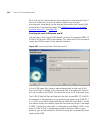
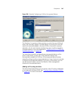
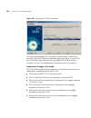
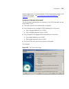
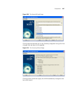
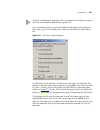
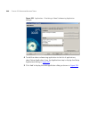
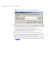
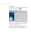
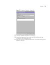
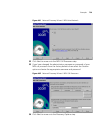
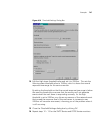
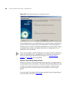
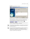
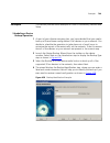
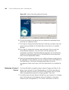
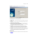
Getting started 37 figure 2 about dialog to activate your software: 1 click activate now to launch the activation wizard. 2 the wizard will ask you for your license key. Enter the key and click next. 3com network director will then direct you to a 3com activation website to retrieve your activation ...
Page 42
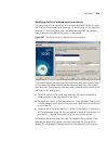
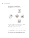
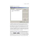
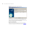
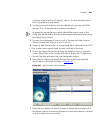
38 c hapter 1: g etting s tarted ■ open an existing map ■ open the last map you were using creating a new network map to create a new map, select create a new network map and click ok to launch the network discovery wizard. Follow the steps in the wizard to initiate discovery of your network as foll...
Page 43
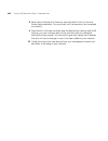
Getting started 39 discovery options step you can choose what types of devices you want to discover on your network. By default, 3com network director will discover and map all devices on your network. Scheduled discovery step if you want to regularly discover your network in order to keep it up-to-...
Page 44
40 c hapter 1: g etting s tarted using saved network supervisor maps you can load maps generated with network supervisor into network director and they will be automatically upgraded for use with network director, but with the following restrictions: ■ all stress monitoring will initially be disable...
Page 45
Getting started 41 if you save an upgraded map from within 3com network director you will be unable to subsequently load it back into 3com network supervisor. Using saved 3com network supervisor files you cannot access the following 3com network supervisor files from within 3com network director: ■ ...
Page 46
42 c hapter 1: g etting s tarted main features this section outlines the main features in 3com network director, with references to the relevant chapters where each feature is described in more detail. Main window the map and tree within the main window provide the main interface for viewing and man...
Page 47
Main features 43 the event system the 3com network director event system provides a constantly updated log of activity on your network and can be used to view and take action on abnormal network conditions before they cause problems. The event system offers filtering tools to allow you to view only ...
Page 48
44 c hapter 1: g etting s tarted bulk configuration the bulk configuration feature allows you to change the software configuration of multiple devices in a single operation. The settings that you wish to administer can be defined by creating a configuration template to be applied to the devices duri...
Page 49
Main features 45 reporting the reporting facility enables you to retrieve stored information about your 3com devices. Many of the features in 3com network director have their own reports but there are other, general purpose reports which give you different views of your 3com devices. You can also cr...
Page 50
46 c hapter 1: g etting s tarted.
Page 51: Roduct
2 p roduct a ctivation introduction 3com network director uses an activation system which allows you to use your copy of the software beyond the evaluation period. This chapter describes how to activate 3com network director. Once you have installed 3com network director, you can use it for a evalua...
Page 52
48 c hapter 2: p roduct a ctivation key concepts 3com network director uses the following information in the activation process: ■ the serial number — 3com network director automatically generates this number when it is first installed. ■ the license key — identifies the physical copy of the softwar...
Page 53
Components 49 figure 3 about dialog before registration when the evaluation period has expired, most menu options are disabled. However, you can still activate the product using the help > activate now menu option or by clicking activate now in the about dialog. You can close the dialog without acti...
Page 54
50 c hapter 2: p roduct a ctivation the wizard consists of two steps as follows: 1 entering the license key — the key can be found inside the cd sleeve of your 3com network director software. The license key is five groups of hexadecimal characters separated by dashes. For example: 3nd - 1bf9 - 093b...
Page 55
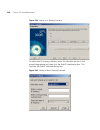
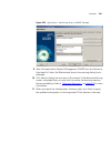
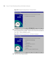
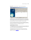
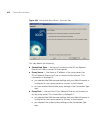
Components 51 figure 5 activation wizard - activation key the wizard already knows the product number and serial number so you do not have to type them in. To obtain the activation key for this copy of 3com network director, click get activation key. This launches your default web browser, which dis...
Page 56
52 c hapter 2: p roduct a ctivation 3com strongly recommends that a software upgrade service agreement is purchased with each copy of 3com network director, as product updates to 3com network director will only be made available to customers with current service agreements. Without a current service...
Page 57
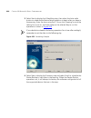
Useful information and references 53 4 in the activation key step, click get activation key. Your default web browser is launched which automatically directs you to the 3com registration site. If the wizard fails to launch your web browser, you can go directly to 3com’s registration system by openin...
Page 58
54 c hapter 2: p roduct a ctivation what product number is right for me? If you have not previously purchased 3com network supervisor advanced package v2.0, you must order 3com network director product number 3c15500 from your reseller. If you have previously purchased 3com network supervisor advanc...
Page 59
Key considerations 55 machine the software is installed on). To comply with the software license agreement you must remove the original installation. If i re-install the product after it has been activated, do i need to activate it again? No - the product activation information is stored on your com...
Page 60
56 c hapter 2: p roduct a ctivation advanced package v2.0 will not be accepted on the new workstation. You must therefore do the following: 1 contact 3com customer support to revoke the existing activation key for advanced package v2.0. 2 install 3com network supervisor v4.0 and advanced package v2....
Page 61
Key considerations 57 before installing 3com network director, you must ensure that 3com network supervisor advanced package v2.0 is unlocked: 1 launch 3com network supervisor v4.0 2 if the registration information dialog box is not displayed at startup, select the help > register now menu option to...
Page 62
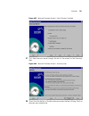
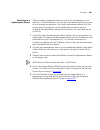
58 c hapter 2: p roduct a ctivation 3 enter the license key found inside the cd sleeve of your 3com network director software and click next. 4 click on activate now to register 3com network director and obtain your activation key from the 3com web site. 5 enter your activation key in the activation...
Page 63
Troubleshooting 59 if the activation key is rejected, this probably means that the workstation on which you installed 3com network supervisor advanced package v2.0 is not the same as the one for which you originally obtained an activation key; if that is the case, please refer to “i want to install ...
Page 64
60 c hapter 2: p roduct a ctivation.
Page 65: Ain
3 m ain w indow overview this chapter describes the 3com network director main window. The main window provides access to all of the features in 3com network director. This chapter covers the following topics: ■ key concepts ■ components ■ examples ■ key considerations.
Page 66
62 c hapter 3: m ain w indow key concepts this section describes some 3com network director key concepts relating to the main window. Map files 3com network director stores device and topology information in map files. Map files have the file extension .Map. Only one map file may be open at any one ...
Page 67
Components 63 components the following section describes the features of the main window and describes the operations you can perform from this window. Map the map provides a graphical representation of the topology of your network. The map is covered in more detail in “working with the map” on page...
Page 68
64 c hapter 3: m ain w indow selected link from ” ” to ” ” for example, if you were to select a link that connected a router with the label new york wan router to a cloud with the label acme isp network that was only connected to by wan links, the text displayed would be: selected link from router ”...
Page 69
Components 65 edit table 4 lists each menu item for the edit menu and the associated operation invoked by selecting it. Table 4 edit menu file > save as saves the current map file using a specified name. See “saving and opening maps” on page 206 for more information. File > export > to visio exports...
Page 70
66 c hapter 3: m ain w indow view table 5 lists each menu item for the view menu and the associated operation invoked by selecting it. Table 5 view menu edit > delete ctrl+delete deletes the selected map item or link. See “deleting items from the map” on page 204 for more information. Edit > group d...
Page 71
Components 67 view > annotate aggregated links toggles whether the link annotations for aggregated links are displayed in the map or not. See “physical link annotations” on page 164 for more information. View > annotate duplex mode toggles whether the link annotations for link duplex modes are displ...
Page 72
68 c hapter 3: m ain w indow view > labels > mac address selects the display of the mac address label for map items in the tree and map. See “map item labels and address translation” on page 175 for more information. View > background image > set background image sets the background image to display...
Page 73
Components 69 device table 6 lists each menu item for the device menu and the associated operation invoked by selecting it. Table 6 device menu view > zoom > fit to page centers the map on the display and zooms in or out as necessary so that the entire map is visible in the display. See “navigation”...
Page 74
70 c hapter 3: m ain w indow monitoring table 7 lists each menu item for the monitoring menu and the associated operation invoked by selecting it. Table 7 monitoring menu device > setup launches the setup wizard. See “device setup wizard” on page 792 for more information. Device > agent update launc...
Page 75
Components 71 alerts/events table 8 lists each menu item for the alerts/events menu and the associated operation invoked by selecting it. Table 8 alerts/events menu rmon table 9 lists each menu item for the rmon menu and the associated operation invoked by selecting it. Table 9 rmon menu monitoring ...
Page 76
72 c hapter 3: m ain w indow tools table 10 lists each menu item for the tools menu and the associated operation invoked by selecting it. Table 10 tools menu menu item hot key operation rmon > statistics launches the statistics view dialog box for the selected item. See “viewing data from the rmon s...
Page 77
Components 73 help table 11 lists each menu item for the help menu and the associated operation invoked by selecting it. Table 11 help menu file > lock menu option this operation locks the 3com network director user interface and prompts for the application password. The password prompt prevents too...
Page 78
74 c hapter 3: m ain w indow unauthorized access when you leave your workstation unattended with the application running. If you have not yet enabled password protection, the following message will be displayed: figure 7 enable password protection message see “security” on page 85 for more informati...
Page 79
Components 75 figure 9 scheduled tasks menu option the scheduled tasks dialog box displays a list of all currently scheduled tasks. Operations that may be scheduled include device backup, agent update and network discovery. Each task has a name, a start time and how often the task repeats (if applic...
Page 80
76 c hapter 3: m ain w indow ■ restore ■ setup ■ prioritize network traffic ■ network discovery then the following operations are prohibited: ■ file > new ■ file > open ■ edit > add device ■ edit > delete the following commands are not blocked if they are currently running: ■ device > backup ■ devic...
Page 81
Components 77 ■ internet — how 3com network director should connect to the internet. ■ discovery — discovery options available to 3com network director. ■ monitoring — default global monitoring options. ■ logging — options for logging historical monitoring data. ■ vlans — how 3com network director s...
Page 82
78 c hapter 3: m ain w indow figure 10 general tab ■ mac addresses — for any mac address displayed, you can append the manufacturer’s name to the start by enabling the translate macs option. For example, 08-00-8f-xx-xx-xx becomes 3com-xx-xx-xx. This option is disabled by default. See “vendor transla...
Page 83
Components 79 figure 11 device management tab choose from web management, which is the default, telnet management or administration application. If a device does not support the preferred web management application, telnet is launched instead. For further information on the device management options...
Page 84
80 c hapter 3: m ain w indow internet this tab, as shown in figure 12 , allows you to set the following options: ■ use web browser settings — this is the default option. If your web browser uses a proxy server to access the internet, 3com network director will use the same system. Figure 12 internet...
Page 85
Components 81 discovery this tab, as shown in figure 13 , allows you to schedule discovery operations to repeat at specified times. Select from repeating every x hours or at a specific time every day, weekday, or week. It also allows you to select the types of devices to discover during network disc...
Page 86
82 c hapter 3: m ain w indow figure 14 monitoring tab for further information on the monitoring tab see “controlling monitoring type and polling rates” on page 296 . Logging this tab, as shown below, displays the following: ■ maintain monitor history for — when monitoring is enabled for a map item, ...
Page 87
Components 83 figure 15 logging tab ■ store history before and after events for— when an event is logged, 3com network director can store a monitoring history for the time period surrounding the event for the monitor(s) that caused the event to occur. This allows you to review the cause of the event...
Page 88
84 c hapter 3: m ain w indow vlans this tab, as shown in figure 16 , displays the following: ■ vlan ids — whether to list vlans that could not be correlated with each other but that have the same vlan id as a single vlan or multiple vlans. They will be listed as multiple vlans by default. Figure 16 ...
Page 89
Components 85 figure 17 retry/timeout tab for further information on the retry/timeout tab, see “using 3com network director on a multi-site network” on page 681 . Security this tab as shown in figure 18 , allows you to specify whether 3com network director should request a password when the applica...
Page 90
86 c hapter 3: m ain w indow figure 18 security tab ■ password required to open application — enable this option if you would like 3com network director to prompt for the application password whenever the application is launched, and when you explicitly lock the application using the file > lock men...
Page 91
Components 87 when password protection is enabled 3com network director shows the following password prompt whenever you launch the application, and when you lock the application using the file > lock menu option: figure 19 password prompt to access the 3com network director user interface you must ...
Page 92
88 c hapter 3: m ain w indow help > about 3com ® director menu option when you launch 3com network director for the first time, the about dialog box is displayed. The dialog box shows the product name, product number, serial number and the major version number. Any service packs installed are also l...
Page 93
Examples 89 figure 21 about dialog box - version number and service pack level finding the serial number, license number and activation key you have a query about an aspect of 3com network director functionality and contact 3com support. The support engineer asks you for your 3com network director s...
Page 94
90 c hapter 3: m ain w indow figure 22 about dialog box - license number 3 the license number is located on the fourth line of the dialog box. 4 the activation key is located on the fifth line of the dialog box. If you have not yet entered the license number and activation key then the about dialog ...
Page 95: Iscovering
4 d iscovering the n etwork overview this chapter describes how 3com network director discovers information about your network. Before you can use 3com network director to manage your network you must instruct it to perform a network discovery. This chapter explains the discovery process, and how to...
Page 96
92 c hapter 4: d iscovering the n etwork key concepts the discovery process can be initiated in a number of ways detailed later in this chapter. This section explains the key concepts behind the discovery process itself. The process is divided into two distinct operations – detecting the devices tha...
Page 97
Key concepts 93 9 device sizing with the exception of the sizing stage (explained below), each of the stages runs sequentially, and the sequence is repeated for each subnet that is being discovered. The sizing stage runs once only, when all the other stages have been executed for all of the subnets ...
Page 98
94 c hapter 4: d iscovering the n etwork the web and telnet menu options on the right-click menu. For certain 3com devices additional information can be obtained using http – see “web type recognition” and “nbx phone detection” on page 95 snmp type detection this stage only applies to devices that w...
Page 99
Key concepts 95 the end station stage attempts to determine an end station’s type by performing the following steps: 1 attempting to start a telnet session with the device and subsequently parse the login banner if the telnet service is supported. 2 determining if the node is operating as a file ser...
Page 100
96 c hapter 4: d iscovering the n etwork with that nbx chassis. This allows 3com network director to identify the existence of phones which would not normally be detected. Nbx phones can be configured to work with or without an ip address. Those with just a mac address will be added to the 3com netw...
Page 101
Key concepts 97 discovered by the previous detecting devices operation are physically connected together. The topology process starts when all discovery operations have completed. The topology process is applied to one subnet (or more specifically multinet) at a time. 3com network director uses the ...
Page 102
98 c hapter 4: d iscovering the n etwork to consider during topology. Since the detecting devices operation has already sized each device, it does not need to communicate with the devices again. Information obtained from the devices is also used to establish whether they are supported by 3com networ...
Page 103
Key concepts 99 initial endstation stage during this stage an attempt is made to identify the ports that have only learned a single address. This is done by reading bridge address tables. The purpose of this stage is two-fold: ■ to eliminate the need for many end station addresses having to be consi...
Page 104
100 c hapter 4: d iscovering the n etwork devices may not support remote poll. If either the write community string is not known for a device or it does not support remote poll then the accuracy of the deduced topology may be reduced. Outstanding end station stage not all end stations will be resolv...
Page 105
Key concepts 101 figure 23 clouds – unknown topology the switch port cannot be physically connected to two end stations, and as such 3com network director inserts the cloud to indicate that there is something missing. In this case the cloud is where the unmanaged hub should be. A similar situation c...
Page 106
102 c hapter 4: d iscovering the n etwork figure 24 edge switch – unknown topology you can identify which switch is the problem device here by checking if unit and port information has been successfully retrieved for each link to each switch. Hover the mouse over the end of the link nearest each swi...
Page 107
Key concepts 103 director at the end of the discovery process. Always check the discovery report first when your discovered network map appears to be incorrect. Sometimes clouds appear in the core of the network when a key, core device has not been discovered properly: figure 25 clouds – core device...
Page 108
104 c hapter 4: d iscovering the n etwork wireless clients clouds these are shown directly connected to a wireless access point on your map. They are used to indicate the number of wireless clients connected to the access point. Wan clouds these are shown on the map between the two end points of a w...
Page 109
Key concepts 105 once 3com network director completes its additional discovery it then updates the main database (and subsequently the map) with the newly discovered information. It does this by comparing the information that exists in the main database with that in the new, temporary database. The ...
Page 110
106 c hapter 4: d iscovering the n etwork scheduled discoveries you can instruct 3com network director to perform scheduled rediscoveries of your network. Note that you can only schedule a rediscovery, you cannot schedule your first discovery on an empty map. A scheduled discovery is always a repeat...
Page 111
Components 107 ■ tools > network discovery menu option with a discovered subnet selected ■ tools > network discovery menu option with an undiscovered subnet selected the welcome dialog box when 3com network director is opened it displays the welcome dialog box: figure 26 welcome dialog box if you ha...
Page 112
108 c hapter 4: d iscovering the n etwork tools > network discovery with nothing selected with no subnets selected in the tree or map, select network discovery from the tools menu. The network discovery wizard will be launched at the first pane discovery type. Tools > network discovery with a discov...
Page 113
Components 109 tools > network discovery with an undiscovered subnet selected if you have already performed a discovery operation, and a router was detected during that discovery, then it is likely that you will have some undiscovered subnets on your map. These subnets will be those to which the rou...
Page 114
110 c hapter 4: d iscovering the n etwork discovery type pane this is the first pane of the wizard: figure 29 discovery type pane it allows you to specify how the list of subnets to discover is determined: ■ local subnet – select this radio button and click next to discover only the subnet to which ...
Page 115
Components 111 ■ specify subnets – select this radio button and click next to specify exactly which subnets you wish to discover and also limit the ranges of ip addresses to discover on each subnet. Use the specify subnets pane to enter the subnets you want to discover. Specify subnets pane this pan...
Page 116
112 c hapter 4: d iscovering the n etwork figure 31 add subnet dialog box you must enter at least the ip address and subnet mask into the appropriate fields for the subnet you wish to specify. You can use the dot ‘.’ key to move to the next segment of an address field. If you wish to limit the range...
Page 117
Components 113 figure 32 add range dialog box this allows you to enter the start and end ip addresses of the range to detect. To discover a single ip address on a subnet, add a range with the same start and end ip address. An existing range can be modified by selecting the range and clicking edit. T...
Page 118
114 c hapter 4: d iscovering the n etwork discovering is routed over a slow or high latency connection. Changing these settings will also affect subsequent discoveries and monitoring of this subnet. See “using 3com network director on a multi-site network” on page 681 for more information. Click ok ...
Page 119
Components 115 figure 33 find subnets list select one or more subnets from the list, and click ok to add them to the list of subnets to be rediscovered. You can then edit their range and retry/timeout values as normal. 3com network director communicates with the routers on your local subnet in order...
Page 120
116 c hapter 4: d iscovering the n etwork figure 34 query failure dialog box if you want 3com network director to continue searching for subnets using the router highlighted in this dialog box, enter the correct read community for the router and select ok. Click cancel to move onto the next router. ...
Page 121
Components 117 # subnet import file # # address mask range start range end 10.0.0.0 255.255.255.0 10.0.1.0 255.255.255.0 10.0.1.1 10.0.1.100 10.0.5.0 255.255.255.0 10.0.5.50 10.0.5.160 10.0.5.0 255.255.255.0 10.0.5.200 10.0.5.210 if the file that you select is correctly formatted and contains valid ...
Page 122
118 c hapter 4: d iscovering the n etwork figure 35 monitor core devices and links pane if you choose the yes radio button then monitoring of the discovered devices will be started when discovery is complete. By selecting the no radio button no monitoring on the new devices will start at the end of ...
Page 123
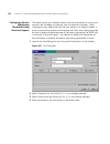
Components 119 figure 36 community strings pane typically, for security reasons, you will modify the community strings on your snmp devices from their factory default settings. In this case, you will need to specify the modified community strings in this pane, otherwise 3com network director will no...
Page 124
120 c hapter 4: d iscovering the n etwork strings to some of your devices (for instance you may have assigned different strings to your routers and switches) then you should add all the entries to the list boxes. If you are rediscovering an existing subnet and haven’t changed the community strings o...
Page 125
Components 121 (http) only – they do not support the snmp protocol. When you access an ncp device with you web browser you will be asked for a username and password. 3com network director uses the same username and password to obtain information from ncp devices. See “key concepts” on page 92 . It i...
Page 126
122 c hapter 4: d iscovering the n etwork discovery options pane this step of the wizard allows you to restrict the type of devices that the discovery process will add to the map: figure 39 discovery options pane you may wish to do this for the following reasons: ■ to filter out devices from the map...
Page 127
Components 123 ■ radius servers ■ snmp-enabled servers only ip devices as described in the “key concepts” section on page 92 , the topology part of discovery can result in mac-only nodes being created as a result of the information read from bridge fdb tables. By selecting this option this behavior ...
Page 128
124 c hapter 4: d iscovering the n etwork discovery options and scheduled discovery whenever a network discovery is started from the network discovery wizard, the settings that you selected in the discovery options pane are stored as the default discovery options for the subnets selected for discove...
Page 129
Components 125 figure 41 options dialog box - discovery tab the discovery tab allows you to specify how discoveries will be scheduled in the future. The options on this dialog box are as follows: never select this option to schedule no future discoveries.Note that if there is currently a pending sch...
Page 130
126 c hapter 4: d iscovering the n etwork at … select this option to schedule a discovery for a specific time each day. Alternatively it allows you to specify it to run on specific day of the week or on every week day (i.E. Monday to friday) discovery global defaults the discovery global defaults pa...
Page 131
Components 127 figure 42 network discovery wizard - summary pane when you click finish on this, or any other step of the wizard, 3com network director attempts to start the discovery process, using the options you have specified. If there is a conflicting task currently running, the standard task in...
Page 132
128 c hapter 4: d iscovering the n etwork figure 43 task in progress dialog box the network discovery progress dialog box the network discovery progress dialog box is displayed while the discovery process is running. The process starts when you click finish on the network discovery wizard, or when a...
Page 133
Components 129 if the discovery was started as a result of a scheduled discovery the dialog box will first appear in its minimized form. In this case a progress bar appears in the status bar of the main window, indicating that it is performing a discovery: figure 45 network discovery progress dialog...
Page 134
130 c hapter 4: d iscovering the n etwork you can perform other operations on you map while discovery is running, although certain tasks are restricted. Network discovery summary dialog box the network discovery summary dialog box is automatically displayed when the discovery process completes: figu...
Page 135
Components 131 discovery process. It allows you to view the discovery report, using the view report button, to find out what the problems were. Note that this button will be disabled if no problems were encountered. Network misconfigurations: when the discovery process is complete 3com network direc...
Page 136
132 c hapter 4: d iscovering the n etwork these relate to 3com network director not being able to retrieve all the information it requires to accurately depict your network. For example it may have lost communication with some of the devices during the discovery process. The report is divided into t...
Page 137
Components 133 note that the analysis is always performed on the whole of your map, not just the recent additions. You can force a new version of the report to be generated from the tools > reports dialog box, although generally there should be little need to do this since it should be the same as t...
Page 138
134 c hapter 4: d iscovering the n etwork and navigating between the subnets, see “working with the map” on page 151 . Subsequent map updates whenever you perform a discovery on a map that already contains subnets and devices, 3com network director intelligently attempts to update the existing map. ...
Page 139
Examples 135 figure 48 options dialog box - discovery tab 4 enter “12:00” into the time field and select “am” within the am/pm drop-down list. Ensure that the day option is selected in the every drop-down list. 12:00 am is midnight and 12:00 pm is midday. 5 commit your scheduled discovery by clickin...
Page 140
136 c hapter 4: d iscovering the n etwork figure 49 scheduled tasks note that by scheduling a discovery this way you need to have already populated your map with any subnets you wish to regularly rediscover. A scheduled discovery cannot be used to discover new subnets. If you haven’t yet done this t...
Page 141
Examples 137 figure 50 scheduled discovery pane , 4 this will launch the tools > options dialog box at the discovery tab. Enter information into this dialog box as in the above example and click ok to return to the network discovery wizard. 5 complete the wizard as normal and click finish. A discove...
Page 142
138 c hapter 4: d iscovering the n etwork 3 on the specify subnets pane of the wizard, add the subnets you wish to discover ■ if the subnets are all within one router hop of your work station you can use the find subnets button to save having to enter all the information, go to step 8, below. ■ if t...
Page 143
Examples 139 the ranges of addresses on your subnet, 3com recommends that you set the ranges exactly, particularly as you are about to increase the timeout value. 5 uncheck the use defaults from tools > options dialog option. The fields below will now become enabled. Increase the retry and timeout v...
Page 144
140 c hapter 4: d iscovering the n etwork figure 51 community strings pane 3 select the yes option. The add… buttons will now be enabled. 4 use the add button below the read list box to enter the read community string of your routers. 5 use the add button below the write list box to enter the write ...
Page 145
Useful information and references 141 time if it or the network is very busy, or potentially may not receive, or be able to respond to, the icmp ping message if it is placed beyond a firewall. If a device fails to respond to a ping then 3com network director will not add it in to the map as an ip de...
Page 146
142 c hapter 4: d iscovering the n etwork links and wan links are also depicted using clouds. See “clouds” on page 167 for further information. For a detailed list of faqs about the discovery process refer to the advanced help that is supplied with 3com network director. You can view this by launchi...
Page 147
Key considerations 143 ■ routing: it uses mib ii tables to establish if the device has ip-forwarding enabled and has interfaces on multiple subnets. If so it is flagged as a router and will appear on the map at the top level with a diamond border. See “working with the map” on page 151 . ■ switching...
Page 148
144 c hapter 4: d iscovering the n etwork also, you should try to ensure that the ip addresses of the devices on your subnet are all within a small set of ranges, with few or no gaps between the devices on each range and then explicitly specify those ranges in the network discovery wizard. If 3com n...
Page 149
Discovery report errors and warnings 145 network director failed to detect any routers whose arp caches contained entries for the mac addresses, possibly because they are outside the ranges of addresses you specified. Alternatively, the appropriate router may have been discovered as an ip-only node ...
Page 150
146 c hapter 4: d iscovering the n etwork 3com network director was unable to obtain information from the following nbx devices this is likely to occur if incorrect usernames or passwords were provided in the wizard. Note that even if you specified in the wizard that you do not have an nbx voice sys...
Page 151
Discovery report errors and warnings 147 the following devices are running with an unsupported version of the management agent software for 3com devices, 3com network director has a minimum supported agent version. If 3com network director detects a device running an agent below this minimum it will...
Page 152
148 c hapter 4: d iscovering the n etwork however is the hubs/switches being configured in a way that is not supported by 3com network director or if 3com network director lost communication with any of the switches when attempting to read topology information from them. In the latter case additiona...
Page 153
Discovery report errors and warnings 149 the following devices have support for the spanning tree protocol enabled. Links connected to these devices may in the future be blocked by the spanning tree protocol. 3com network director may not be able to detect this occurring. Some third party devices do...
Page 154
150 c hapter 4: d iscovering the n etwork 3com network director uses interface speeds when monitoring links in order to calculate utilization. If 3com network director was unable to determine a speed for a connected interface and you start monitoring the link corresponding to that interface then 3co...
Page 155: Orking
5 w orking with the m ap overview this chapter describes how to work with the map and tree in 3com network director. The map and tree provide the main interface for viewing and managing your network. They enable you to choose how you want to view your network, show the current health of monitored de...
Page 156
152 c hapter 5: w orking with the m ap key concepts this section describes the key concepts of the map and the tree within 3com network director. The map the map is displayed on the right-hand side of the 3com network director main window. It presents a graphical representation of your network topol...
Page 157
Key concepts 153 table 12 icons used in the map icon description a diamond icon represents a router or a layer-3 switch. The image within the diamond will indicate the type of the router or layer-3 switch. For more information see “device icons” on page 158 . An octagonal icon represents a network i...
Page 158
154 c hapter 5: w orking with the m ap the tree the tree is displayed on the left-hand side of the 3com network director main window and lists all of the devices that have been discovered in your network, grouped into subnets and device groups. Clouds are not listed in the tree. Clouds appear automa...
Page 159
Key concepts 155 figure 53 example tree to expand a subnet or device group, click the symbol next to its name. It expands to show the discovered devices. To collapse the subnet or device group, click the symbol next to its name. Each device appears only once in the tree. Routers and layer-3 switches...
Page 160
156 c hapter 5: w orking with the m ap the map and the tree work in conjunction with each other. When you select a device, subnet or device group within the tree it is also selected in the map and vice versa. Once you have made your selection: you can use the pull-right menu, in either the tree or t...
Page 161
Components 157 figure 54 subnet example ■ device groups — allow you to manually group together similar devices, to allow you to represent your network more intuitively. Figure 55 device groups example.
Page 162
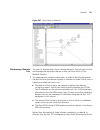
158 c hapter 5: w orking with the m ap submaps can contain shortcut symbols, that indicate that the device that is linked to is not contained in the current map. For more information see “shortcut symbols” on page page 186 . There are various methods that can be used to navigate between the top-leve...
Page 163
Components 159 table 13 network infrastructure device icons device icon description 3com switch 40x0 family device 3com superstack 3 family device 3com superstack 3 family power over ethernet device 3com superstack ii family device 3com switch 7700 3com switch 4007r 3com switch 4005 other 3com chass...
Page 164
160 c hapter 5: w orking with the m ap table 14 nbx networked telephony solution icons 3com wireless lan access point all other network infrastructure devices telephony solution icon description nbx network call processor nbx line card ip telephone analogue telephone fax machine device icon descript...
Page 165
Components 161 table 15 end station icons some device types are drawn slightly differently in the map than other devices. For more information about special support see “graphical support for specific device types” on page 225 . Pull-right menu for devices right-clicking on a device in the map or in...
Page 166
162 c hapter 5: w orking with the m ap historical report launches a historical report for the selected device or link. See “performance reporting” on page 385 for more information. Attach alerts launches the attach alerts dialog box for the selected map items and links. See “attach alerts dialog box...
Page 167
Components 163 physical links physical links between devices, or from devices to clouds, are represented in the map as straight, solid lines, with the thickness of the line representing the speed of the link. The thickness of the lines on the display will vary depending upon the level of zoom in use...
Page 168
164 c hapter 5: w orking with the m ap unvalidated links some links in the map represent links that are unvalidated. Unvalidated links can occur when a rediscovery of a subnet fails to find a link that existed previously, or when you manually add a link to the map. A link remains unvalidated until a...
Page 169
Components 165 spanning tree protocol support 3com network director monitors the spanning tree state of links in your network for which the spanning tree protocol is enabled. The map is dynamically updated to show which links are currently disabled by spanning tree protocol using the annotation indi...
Page 170
166 c hapter 5: w orking with the m ap layer-3 connections layer-3 connections only display when you choose to view devices grouped by subnet. In the top-level map, they are shown as connections between a subnet and a device, for example a router or layer-3 device. Each layer-3 connection represents...
Page 171
Components 167 figure 57 a layer-3 connection logical connectivity is due to the device having one or more ip addresses on the subnet in question. Pull-right menu for layer-3 connections right-clicking on a layer-3 connection in the map produces a pop-up menu. The following table describes each of t...
Page 172
168 c hapter 5: w orking with the m ap discovery. For more information see “there are clouds in my map” on page 141 . ■ they may be used to separate a link into two halves. This can be useful in situations where you would like to monitor both halves of the link separately. Clouds are used to automat...
Page 173
Components 169 cloud should appear in a particular submap or the top-level map is based upon the devices that are connected to it: ■ a cloud will appear in a submap if it is connected to one or more devices that are present in that submap. ■ a cloud will appear in the top-level map if it is only con...
Page 174
170 c hapter 5: w orking with the m ap between subnets and routers or layer-3 switches are shown as physical links. For more information see “navigating between submaps and the top-level map” on page 184 . If a router or layer-3 switch in your network has two or more ip interfaces configured on a si...
Page 175
Components 171 pull-right menu for subnets right-clicking on a subnet icon in the map, or on a subnet entry in the tree, produces a pop-up menu. The following table describes each of the menu items in the pop-up. Table 22 subnets menu options menu item operation start monitoring starts the monitorin...
Page 176
172 c hapter 5: w orking with the m ap 3com network director applies intelligent filtering to ensure that an operation applied to a subnet will apply to all items in the subnet that can meet the requirements of the operation. This gives you a convenient way to apply operations to a complete ip subne...
Page 177
Components 173 from the submap’s branch and move the individual devices to within the submap’s branch. Pull-right menu for device groups right-clicking on a device group in the map, or in the tree, produces a pop-up menu. The following table describes each of the menu items in the pop-up. Table 23 d...
Page 178
174 c hapter 5: w orking with the m ap operations applied to a device group will apply to all devices contained within the device group. 3com network director will intelligently filter out any items from the selection which don't make sense in the context of the requested operation. This gives you a...
Page 179
Components 175 connection is based upon the map item connected to the end nearest the half that the mouse is held over. The following table describes the information displayed: table 24 tooltip displays map item labels and address translation the view > labels menu allows you to select the type of l...
Page 180
176 c hapter 5: w orking with the m ap if 3com network director is unable to obtain a label of the type you have selected, then it will use the first label that it is able to locate (using the label type label source custom name manually specified. For more information about how to set the custom na...
Page 181
Components 177 order in table 25 ). For example, 3com network director will not be able to determine the user name for a cloud, and so will use the custom name if it is set, or the system name otherwise. Vendor translation of mac addresses the mac address of a device is divided into two 24-bit halve...
Page 182
178 c hapter 5: w orking with the m ap figure 61 mac address label display (2) by default, the automatic translation of the oui of mac addresses is turned off. To toggle this feature on or off, launch the tools > options dialog box and, from the general tab, set the translate macs option:.
Page 183
Components 179 figure 62 the translate macs option toggling this option affects the display of mac addresses in all areas of 3com network director other than in the reports, which always display the raw mac addresses. 3com network director3com network director uses a list of fixed mappings from oui ...
Page 184
180 c hapter 5: w orking with the m ap selecting items in the map and tree in order to select an item in the map or the tree single-click on its icon. This will select the item both in the map and in the tree. To add additional items to the selection you can then press and hold the ctrl key while si...
Page 185
Components 181 figure 63 selecting multiple map items for the purposes of selection, a map item is considered to be within the selection rectangle if it is either wholly contained within the selection rectangle, or if the selection rectangle overlaps with its icon. Note that this method of selection...
Page 186
182 c hapter 5: w orking with the m ap device group. It will not select the members of the subnet or device group. Selection and the pull-right menu the pull-right menu and its options interacts with selection in various ways: ■ if you launch the pull-right menu for an item that is not currently sel...
Page 187
Components 183 zoom out zooms out from the map, keeping the center of the currently displayed area of the submap centered in the zoomed out display. Fit to page centers the entire contents of the currently viewed submap on the display and zooms in or out so that the entire contents of the submap are...
Page 188
184 c hapter 5: w orking with the m ap unlike the selection rectangle, which may have any proportions, the zoom rectangle keeps the proportions of the map display area to indicate the complete area that will be visible when you release the mouse button. This may mean that when you are dragging the z...
Page 189
Components 185 figure 65 up button the goup action cannot be performed from the top-level map. ■ enter submap — navigates directly to the submap associated with the subnet or device group being entered. The enter submap action can be performed either by selecting view > enter submap, by selecting en...
Page 190
186 c hapter 5: w orking with the m ap table lists each menu item that may appear in the menu and the associated operation. Table 28 pull-right menu options from the map background . Shortcut symbols you may have two devices on your network that are physically linked to each other, but that do not e...
Page 191
Components 187 table 29 shortcut icon you can use shortcut icons to navigate to the submap that contains the device. Either double-click on the shortcut icon, or select follow link from the pull-right menu of the shortcut icon. This navigates to the submap, selects the device, centers it on the disp...
Page 192
188 c hapter 5: w orking with the m ap to zoom to a device in the map, double-click on its entry in the tree. 3com network director navigates to the submap that the device is listed under, centers the device within the display, and zooms in on the device. As routers and layer-3 switches are shown in...
Page 193
Components 189 figure 66 trace path example if you launch trace path without first selecting the two devices that you want to find the physical paths for, the toolbar is launched alongside the wizard. However, the toolbar buttons are only enabled once you have completed the selection of the two devi...
Page 194
190 c hapter 5: w orking with the m ap table 30 previous and next path buttons changing the displayed path changes the path that is highlighted in the map. Using the filtered trace path view trace path also provides a separate filtered view that shows only those map items included in the currently v...
Page 195
Components 191 when you change the viewed path in the filtered trace path view, the devices that form the path, or the order in which the devices are displayed in the path, may change. As a result some devices may be removed from the view, others may be added and the layout may change. Using the tra...
Page 196
192 c hapter 5: w orking with the m ap results table. In this situation, you may either select the device to use as one of the end points of the path from the results table and click next to use it, or click back and enter new search criteria. If you have only one device selected when you select too...
Page 197
Components 193 to find items on your network from within the find dialog box, simply select appropriate search criteria to locate the required items, and click the find button. 3com network director will then examine the contents of the map and list the items that match your selected search criteria...
Page 198
194 c hapter 5: w orking with the m ap the wildcards supported by 3com network director are shown in the following table: table 31 wildcard characters for example: ■ to find all devices that include the text switch in their name, select find: devices search by: name and enter the name: *switch*. ■ t...
Page 199
Components 195 using the find dialog box to select items for operations there are various operations in 3com network director for which you must first select a list of items to perform the operation on before you may proceed, such as selecting a list of devices that are to have their configuration b...
Page 200
196 c hapter 5: w orking with the m ap mac address finds devices that have a mac address that matches the entered mac address. You may use wildcards in any of the six fields of the mac address. If you use wildcards, or leave one or more fields of the mac address blank, and a device has more than one...
Page 201
Components 197 finding links the find: links option allows you to find links on your network. The following search by: options are available: table 33 find links, search by: options sysobjectid finds devices whose mib-ii sysobjectid matches the entered sysobjectid. The sysobjectid must be entered in...
Page 202
198 c hapter 5: w orking with the m ap finding nbx telephony components the find: nbx telephony components option allows you to find nbx telephony components on your network. Nbx telephony components include such devices as nbx call processors, line cards and nbx phones. The following search by: opt...
Page 203
Components 199 table 34 find: links, search by: options search by: option description name finds nbx telephony components whose custom name, dns name or system name matches the entered name. You may use wildcards in the value that you enter in the name: field. User name find nbx telephony components...
Page 204
200 c hapter 5: w orking with the m ap modifying the map layout whenever you perform a network discovery 3com network director automatically organizes the representation of your network, or newly discovered portions of your network, in as compact and intuitive a manner as possible. However, the layo...
Page 205
Components 201 if you want to change the layout of a map, you can either lay out the map manually, or request an automatic relayout of the current map. Manual layout of map items in order to change the layout of map items select the map item that you wish to move, click and hold the mouse pointer ov...
Page 206
202 c hapter 5: w orking with the m ap figure 72 3com network director warning message relaying out the entire map will generally result in a better map layout. Manually modifying the map contents by default the map only displays devices that 3com network director has itself discovered on your netwo...
Page 207
Components 203 figure 73 add map item dialog box you can add items to the map by locating the entry for the type of item you wish to add in the list, and clicking and dragging the entry to the location in the map where you wish it to be located. The add map item dialog box remains visible until you ...
Page 208
204 c hapter 5: w orking with the m ap items to several submaps without having to launch the dialog box for each submap. A newly added cloud is initially present only in the submap that you add it to. However, as soon as you add a link to the cloud the normal cloud behavior takes over. For more info...
Page 209
Components 205 keeping the map up-to-date by carrying out rediscoveries of your network at regular intervals 3com network director maintains the map’s topology and keeps it up-to-date with the physical layout of your network. You can also carry out manual rediscoveries or automate them by setting a ...
Page 210
206 c hapter 5: w orking with the m ap the map and the map already contains 5000 devices then the end station will not be added to the map, and an event logged in the event list. For more information see “the event log” on page 319 . Saving and opening maps to create a new empty map file and launch ...
Page 211
Components 207 once you have saved a map you can exit 3com network director, or use another map, and then later restore the saved map at the point where you saved it. To restore a saved map select file > open and locate the map that you wish to open. 3com network director retains a history of the sa...
Page 212
208 c hapter 5: w orking with the m ap figure 74 default map file location you may wish to select a default location that is backed-up regularly, such as on a file server, in order to ensure that you do not lose any saved maps in the event of hardware failure. Exporting maps to microsoft visio 3com ...
Page 213
Components 209 figure 75 export to visio dialog box.
Page 214
210 c hapter 5: w orking with the m ap printing the map selecting file > print launches the print map dialog box, which allows you to select how to print the currently visible map: figure 76 print map dialog box ■ selecting the print the currently visible area option will reproduce exactly what is d...
Page 215
Components 211 launches the scale background image dialog box, which allows you to select how the size of the image should be determined. Figure 77 scale background image dialog box if you subsequently wish to resize the background image for the currently viewed submap, select view > background imag...
Page 216
212 c hapter 5: w orking with the m ap if you have cleared the view > background image > show background images toggle in order to temporarily hide background images and subsequently set or resize a background image for a submap, the toggle will automatically be re-enabled, turning on the display of...
Page 217
Examples 213 figure 79 the search by: list 4 select 3com switch 4400 from the device type: list. Figure 80 selection on the device type: list 5 click find to search for the devices, and wait until the search has completed..
Page 218
214 c hapter 5: w orking with the m ap figure 81 search results table 6 select a row in the results table and then press ctrl + a to select all of the superstack switch 4400 devices in your network. Figure 82 devices selected 7 select tools > reports to launch the capacity report..
Page 219
Examples 215 viewing all of the physical connections for a router you are currently viewing the devices in your network grouped by subnet and need to see all of the physical connections for a particular router that is logically connected to multiple subnets. 1 toggle the view > group map by subnet o...
Page 220
216 c hapter 5: w orking with the m ap figure 84 double-clicking on a router in the tree.
Page 221
Examples 217 focusing in on a set of devices in the map you are viewing the devices in your network grouped by subnet, are in the top-level map, and wish to focus in on the servers on a particular subnet. 1 double-click, either in the map or in the tree, on the subnet that the servers are in. The ma...
Page 222
218 c hapter 5: w orking with the m ap figure 86 selection of multiple servers 3 click on the zoom in button in the toolbar. This centers the display around the selected servers and zooms in: figure 87 zooming in.
Page 223
Examples 219 4 repeat click on the zoom in button in the toolbar until the servers are at the level of magnification desired: figure 88 adjusting the magnification.
Page 224
220 c hapter 5: w orking with the m ap adding a link between map items from different submaps you are viewing the devices in your map grouped by subnet, and you wish to add a link between two devices that are on different submaps. 1 locate the two devices in the tree, select the first one with a sin...
Page 225
Examples 221 figure 90 selecting edit > add link it is not necessary for either of the devices to be visible in the display in order to link them in this way. Adding a new device on your network into the map you have just connected a new stackable switch to the network, and wish to add it into the m...
Page 226
222 c hapter 5: w orking with the m ap if you are viewing the devices in your network grouped by subnet then you need to locate and navigate to the subnet that the new switch is present on, so that the device is present in the correct submap. 1 find the submap in the tree and double-click on it to o...
Page 227
Examples 223 figure 92 selecting edit > add map 3 click and drag the stackable switch icon across into the location in the map where you wish the switch to be placed and drop the icon there. Figure 93 moving the stackable switch icon.
Page 228
224 c hapter 5: w orking with the m ap 4 having added the switch, close the add map item dialog, right-click on the new icon and select properties from the pull-right menu. Figure 94 selecting properties use the properties dialog to set the ip address of the new device. For more information about ho...
Page 229
Useful information and references 225 useful information and references the following section provides useful support details related to the map and tree. Graphical support for specific device types some device types have specific graphical support in the map. This section provides details of the sp...
Page 230
226 c hapter 5: w orking with the m ap if a wireless access point is being monitored then 3com network director will monitor the number of clients connected to the wireless access point and dynamically update the contents of the cloud to reflect the results of its monitoring. Figure 96 clients conne...
Page 231
Useful information and references 227 for example, if you choose to save a map with the name corporate core, the following three files will be created: ■ corporate core.Map ■ corporate core.Properties ■ corporate core events.Edb all three files are saved to the location that you specify when you sav...
Page 232
228 c hapter 5: w orking with the m ap figure 97 network login radius is an ietf standard for a protocol providing authentication and accounting services. It is used as part of 3com’s network login and switch login features. Switch login is a feature which stores the telnet and web username and pass...
Page 233: Iewing
6 v iewing d evice d etails overview this chapter describes how to view detailed information about your networking equipment and apply new settings using the properties dialog box. The properties dialog box is available after the network has been discovered. It allows you to: ■ view detailed informa...
Page 234
230 c hapter 6: v iewing d evice d etails key concepts this section outlines the key concepts of working with the properties dialog box in 3com network director. Items supported by the properties dialog box 3com network director can display the properties of any item on the network map. This include...
Page 235
Components 231 to do this: 1 select the item(s). You can do this by: ■ clicking on the item’s icon on the map. ■ clicking on the item’s name in the network tree. ■ selecting an area of the network map by dragging the mouse while the left mouse button is pressed. 2 using the device > properties menu ...
Page 236
232 c hapter 6: v iewing d evice d etails figure 98 tabbed pane for a device table 36 gives a description of the information displayed for each tab. Table 36 description of the tabs in the properties dialog box tab title contents general general information regarding the item, such as name, type and...
Page 237
Components 233 the device tree if the selected map item is a networking device, the left-hand side of the dialog box shows a tree, as shown in figure 99 . Vlans vlan information for the item, such as the vlans configured on the device or the vlan the selected end-station is part of. Phone informatio...
Page 238
234 c hapter 6: v iewing d evice d etails figure 99 the device tree the tree presents the structure, as units/slots and ports, of the selected device. The device tree lists the following: ■ device — this is the root of the tree. It represents the whole device. The label displayed in the tree corresp...
Page 239
Components 235 ■ the unit index within the stack and the type of unit. ■ the slot index within the chassis and the type of blade. ■ port — this is displayed under the device tree node if the device consists of only one unit, or under the unit tree node if there are several units within the device or...
Page 240
236 c hapter 6: v iewing d evice d etails by default, only units and aggregated links are displayed in the tree. To display ports within a unit you need to expand the corresponding tree node to view its contents. To expand a tree node and view the contents, click on the + icon next to the folder ico...
Page 241
Components 237 properties dialog box for a supported device if the map item is a device supported by 3com network director, the properties dialog box shows a tree on the left-hand side of the dialog box, with the tabbed pane on the right-hand side of the dialog box. The tree shows the individual por...
Page 242
238 c hapter 6: v iewing d evice d etails table 40 tabs for an aggregated link supported device (stack or chassis) if the device is a stack or a chassis device, the tree on the left-hand side of the dialog box shows the device, the units/slots on the device, the ports on each unit/slot and the ifind...
Page 243
Components 239 figure 100 properties dialog box for a supported device (stack or chassis) select the unit/slot in the tree to view the properties for that unit/blade. The tabs available for a unit/slot are shown in table 41 . Table 41 tabs available for a unit/slot supported device (single unit) if ...
Page 244
240 c hapter 6: v iewing d evice d etails figure 101 properties dialog box for a supported device (single unit) because it is not possible to view the properties of a unit by selecting it in the tree, an additional unit tab is available for the device. That tab shows the information in the same form...
Page 245
Components 241 figure 102 properties dialog box for an unsupported device because 3com network director does not support the device some information might be missing. Whenever information is missing, 3com network director shows n/a indicating that it is not applicable or unknown indicating that 3com...
Page 246
242 c hapter 6: v iewing d evice d etails figure 103 properties dialog box for an end-station because end-stations are usually unmanaged, some information might be missing. Whenever information is missing, 3com network director shows n/a indicating that it is not applicable or unknown indicating tha...
Page 247
Components 243 figure 104 properties dialog for a phone phone tab the properties dialog box for phones displays an extra phone tab. This tab displays information such as: ■ user information for the phone: user title, user name, user department ■ phone information: extension number, location because ...
Page 248
244 c hapter 6: v iewing d evice d etails properties dialog box for a subnet figure 105 properties dialog box for a subnet the tabs available for a subnet are shown in table 42 : table 42 tabs available for a subnet tab title contents general general and custom information for the subnet, such as cu...
Page 249
Components 245 properties dialog box for a device group the properties dialog box for a device group consists of a single general tab, as shown in figure 106 . Figure 106 properties dialog box for a device group the general tab shows the following information: ■ custom name —the name of the device g...
Page 250
246 c hapter 6: v iewing d evice d etails figure 107 properties dialog box for a cloud the general tab shows the following information: ■ custom name — the custom name of the cloud. ■ type — this corresponds to the media types of the links connected to the cloud. For instance: ethernet, atm, fddi, e...
Page 251
Components 247 ■ if the connected interfaces are of different media types, but are all of media types that are commonly used for wan communications then the cloud type is set to “wan”. ■ if the connected interfaces are of different media types, and at least one of them is of a type that is not commo...
Page 252
248 c hapter 6: v iewing d evice d etails figure 108 properties dialog box for a non-wan link the tabs available for a link are shown in table 43 : table 43 tabs available for a non-wan link tab title contents general general information for the link, such as speed, duplex mode, etc. Custom informat...
Page 253
Components 249 properties dialog box for a wan link the properties dialog box for a wan link consists of a tabbed pane. There is no tree on the left-hand side, as shown in figure 109 . Figure 109 properties dialog box for a wan link power over ethernet information regarding the power over ethernet s...
Page 254
250 c hapter 6: v iewing d evice d etails the tabs available for a wan link are shown in table 44 : table 44 tabs available for a wan link properties dialog box for a layer-3 connection the properties dialog box for a layer-3 connection consists of a tabbed pane. There is no tree on the left-hand si...
Page 255
Components 251 figure 110 properties dialog box for a layer-3 connection the tabs available for a link to a subnet are shown in table 45 : table 45 tabs available for a layer-3 connection properties dialog box for a multiple selection when multiple items are selected on the map and the properties di...
Page 256
252 c hapter 6: v iewing d evice d etails figure 111 properties dialog box for a multiple selection the tabs shown in the tabbed pane depend upon the items that have been selected: ■ if the selected items are all of the same type (for example, if they are all physical links, or if they are all devic...
Page 257
Components 253 if three links are selected, one of which is an aggregated link, and the properties dialog box is launched then the general, ports, vlans and monitoring tabs will be displayed; if a node were added to the selection prior to launching the properties dialog box then the general and secu...
Page 258
254 c hapter 6: v iewing d evice d etails applying changes to devices using the properties dialog box this section describes how you can apply changes to items with the properties dialog box. Changing the custom name 3com network director allows you to change the custom name of any item on the netwo...
Page 259
Components 255 4 click ok to save your changes. Setting the ip address for a manually added device when a device is manually added to the map, it does not have an ip address associated with it. 3com network director lets you enter an ip address for that device. To specify the ip address for a manual...
Page 260
256 c hapter 6: v iewing d evice d etails figure 114 addresses tab for a manually added device figure 115 cannot contact the ip address specified assigning an ip address to a manually added device only defines the ip address that 3com network director uses to communicate with the device – it does no...
Page 261
Components 257 setting the port numbers for a manually added link when a link is manually added to the map, it does not specify which ports or interfaces are being used on the devices it connects. 3com network director lets you enter which ports or interfaces are used for the link. To specify port i...
Page 262
258 c hapter 6: v iewing d evice d etails figure 116 ports tab for a manually added link changing the community strings for a device it is possible to specify which community strings 3com network director should use to communicate with a device. This can be useful if a device has had its community s...
Page 263
Components 259 to change the community strings on a device: 1 click on the icon for the device in the 3com network director map to select it. 2 select the device > properties menu option to launch the properties dialog box. 3 select the security tab. This shows the tab shown in figure 117 . 4 if you...
Page 264
260 c hapter 6: v iewing d evice d etails figure 117 security tab for a device.
Page 265
Components 261 figure 118 community strings not accepted once the changes are applied 3com network director uses the new community strings to communicate with the device. Changing the community strings for a device only changes the community strings that 3com network director uses to communicate wit...
Page 266
262 c hapter 6: v iewing d evice d etails monitoring settings can be configured from within the monitoring tab of the properties dialog box: figure 119 monitoring tab of the properties dialog box monitoring settings, and how to change them, are covered in detail in “controlling monitoring type and p...
Page 267
Components 263 retry and timeout settings can be configured from within the retry/timeout tab of the properties dialog box: figure 120 retry/timeout tab of the properties dialog box the use of retry and timeout settings in your network, and how to change them, is covered in detail in “using 3com net...
Page 268
264 c hapter 6: v iewing d evice d etails figure 121 discovery options tab of the properties dialog box details of setting the discovery options for subnets and the effects that they have are given in “discovery options pane” on page 122 . Examples the following section details examples of using the...
Page 269
Examples 265 to view the properties for that port: 1 click on the icon for your switch 4007 on the map to select it. 2 select the device > properties menu option to launch the properties dialog box. 3 to expand the tree and display all the ports on slot 4 of your switch 4007 click on the + sign besi...
Page 270
266 c hapter 6: v iewing d evice d etails figure 122 properties for a specific port how do i change the community strings for all devices in a subnet? You have changed the community strings for all devices in a subnet, and want 3com network director to use these community strings to communicate with...
Page 271
Examples 267 7 enter the new community string in the read and write sections. 8 click ok to validate your changes. 3com network director now uses the community strings you specified to communicate with the selected devices. Figure 123 security tab for multiple devices.
Page 272
268 c hapter 6: v iewing d evice d etails how do i find the version of the agent software on a 3com device? You want to check the version of the software running on your 3com switch. To see the software version running on your switch: 1 click on the icon for the switch in the 3com network director m...
Page 273
Key considerations 269 7 select the only core devices discovery option. 8 complete the wizard. After the network discovery has completed the subnet will be added to your map, containing only the core devices in that subnet. How do i restrict monitoring to snmp traps for a device? You want to keep th...
Page 274
270 c hapter 6: v iewing d evice d etails it is also possible that the snmp requests that 3com network director uses to communicate with the device timed out. If this is the case then the discovery report will indicate that this problem occurred during discovery. For more information on this report ...
Page 275
Key considerations 271 it takes a long time to close the dialog box after assigning an ip address to a manually added device you assigned an ip address to a manually added device and the properties dialog box takes a long time before closing. During that time, a message is displayed which reads: ple...
Page 276
272 c hapter 6: v iewing d evice d etails.
Page 277: Onitoring
7 m onitoring the n etwork overview this chapter describes how 3com network director can be used to monitor the status of the devices and links within your network. Monitoring the status of devices and links within your network allows you to identify possible bottlenecks or trouble spots in the netw...
Page 278
274 c hapter 7: m onitoring the n etwork monitoring and event generation the monitoring system is used as the main source for generating events.When a monitor enters a state that indicates an abnormal network condition it logs an event detailing the cause.Depending upon the monitor it may also log d...
Page 279
Key concepts 275 figure 124 example of how the monitored state is displayed on the map the color of a monitored item represents the highest severity unresolved event for that item, as shown in the table below: table 46 map item color key this coloring scheme also allows you to quickly determine if a...
Page 280
276 c hapter 7: m onitoring the n etwork for details on how to start monitoring an unmonitored device or link, or to stop monitoring a monitored device or link, see “starting and stopping monitoring” on page 293 . For more information on event severities see “event severities” on page 321 monitoring...
Page 281
Key concepts 277 the rate with which an active monitor polls depends upon the type of device that is being polled, the active monitoring mechanism used and the polling configuration.See “using 3com network director on a multi-site network” on page 681 for more information. Passive monitoring: passiv...
Page 282
278 c hapter 7: m onitoring the n etwork service polling 3com network director provides support for monitoring the status of various services that may be provided by servers in your network, including such services as dns, ftp, pop3 and smtp mail.3com network director monitors a service by connectin...
Page 283
Key concepts 279 if an snmp trap is received that does not have a monitor associated with it then 3com network director will use the trap to generate an event directly.For more information see “the event log” on page 319 see “registering 3com network director as an snmp trap destination” on page 304...
Page 284
280 c hapter 7: m onitoring the n etwork ■ if neither end of the link can be monitored then the link cannot be monitored. ■ otherwise, if one end of the link cannot be monitored then use the other end. ■ otherwise, if only one end of the link is currently being monitored then use that end. ■ otherwi...
Page 285
Components 281 figure 125 live graphs window the live graphs window has a similar layout to the main window, with a menu and toolbar at the top and a tree at the left-hand side.However, it uses the right-hand side of the display to show live graphs for monitors. Poll rates when the live graphs windo...
Page 286
282 c hapter 7: m onitoring the n etwork ■ for other devices the hierarchy lists the device as the top-level folder and the known links to the device as nodes below that. Selecting the top-level folder, which is the default, changes the displayed live graphs on the right-hand side of the display to ...
Page 287
Components 283 the length of time for which the history is maintained may be configured via the tools > options dialog box. See “configuring the storage of monitoring data” on page 306 for more information. Each monitor has a menu that can be launched by right-clicking on the monitor’s live graph. S...
Page 288
284 c hapter 7: m onitoring the n etwork figure 127 displaying thresholds for live graph with below-threshold values (forcing display of thresholds and not forcing display of thresholds) if a graph does include values that are near or exceed the high threshold, then both thresholds will already be v...
Page 289
Components 285 some items in the toolbar are not always applicable.When this is the case, the toolbar button is grayed out. Hovering the mouse cursor over a button in the toolbar causes a tooltip for that button to be displayed. The tooltip describes the operation associated with the button. The ope...
Page 290
286 c hapter 7: m onitoring the n etwork table 49 live graphs - view menu table 50 live graphs - help menu more detail dialog box to view more detail on a particular monitor, either right-click on its entry in the live graph display area of the live graphs window and select more detail from the righ...
Page 291
Components 287 the more detail dialog box provides in-depth information about the selected monitor. The main body of text describes what attribute the monitor is monitoring, details the current state of the monitor and, if the monitor is in an abnormal state, describes what may be causing the proble...
Page 292
288 c hapter 7: m onitoring the n etwork figure 130 detailed graph the dialog box consists of the detailed graph, shown at the top, and a section containing view options beneath. The color of the line used to graph the monitor’s state is always shown as green in the graph’s key. However, like the gr...
Page 293
Components 289 figure 131 component values fields showing thresholds the display options section, which is displayed on the right-hand side when the data to graph section is displayed, contains two options for controlling the display of the graphs: show threshold for… and show plot points. The show ...
Page 294
290 c hapter 7: m onitoring the n etwork showing plot points when the show plot points option is enabled, which is the default, the graph highlights the values on the graph that represent the actual retrieved values from the device by drawing a symbol on each of these points. 3com network director d...
Page 295
Components 291 figure 134 graph save as... Dialog box zooming into a graph left-clicking or right-clicking on a graph and dragging the mouse produces a highlighted area. When you release the mouse, the graph zooms in to show your highlighted area in more detail..
Page 296
292 c hapter 7: m onitoring the n etwork zooming in: figure 135 selecting area for zoomed in graph view after zooming in: figure 136 zoomed in graph view.
Page 297
Configuration 293 right-clicking on the graph produces a pop-up menu, on which you can select the auto range graph axes menu option. This option restores the graph to its original unzoomed state. Poll rates when the detailed graph dialog box is displayed for any monitor on a particular device or lin...
Page 298
294 c hapter 7: m onitoring the n etwork stopping monitoring on a set of devices and links can be performed in a similar manner to starting monitoring, but by selecting either monitoring > stop monitoring from the main menu or stop monitoring from the right-click menu instead. When you stop monitori...
Page 299
Configuration 295 when a monitor is disabled the text switched off will be displayed over the monitor.In the live graphs window the graph is otherwise blank: figure 137 disabled monitor screen in the detailed graph dialog box for the monitor, the graph also shows the history for the monitor at the t...
Page 300
296 c hapter 7: m onitoring the n etwork controlling monitoring type and polling rates depending upon the topology and geographical distribution of your network, regular polling of some segments of your network may cause more network traffic than is desirable.In order to address this, 3com network d...
Page 301
Configuration 297 response monitoring: in response monitoring mode 3com network director only enables the ip ping service monitor for a device.All other monitors are disabled and are not displayed in the live graphs window. This greatly reduces the amount of traffic generated by monitoring a device,...
Page 302
298 c hapter 7: m onitoring the n etwork the use of monitoring mode in distributed networks is discussed in section on monitoring mode in “using 3com network director on a multi-site network” on page 681 poll rate active monitors poll the devices in your network to obtain the data they require to ca...
Page 303
Configuration 299 figure 139 monitoring tab of tools > options dialog box if use automatic monitoring is selected, the default, then you may specify the number of important devices to use full monitoring mode for.All other devices will be monitored using the response monitoring mode.In automatic mon...
Page 304
300 c hapter 7: m onitoring the n etwork specifying monitoring mode and poll rates at the subnet level you can only change the monitoring type and poll rate settings for a subnet if you are not using automatic monitoring mode for the whole map.If you are not using the automatic monitoring mode and w...
Page 305
Configuration 301 specifying monitoring mode and poll rates at the device level you can only change the monitoring type and poll rate settings for a device if you are not using automatic monitoring mode for the whole map.If you are not using the automatic monitoring mode and wish to change these set...
Page 306
302 c hapter 7: m onitoring the n etwork control. A checkbox will be shown with a tri-state value. A radio button will be shown with no initial selection. A text field will be shown with no initial value. When you click ok, any changes you have made will be applied to all selected devices. If you st...
Page 307
Configuration 303 figure 142 monitoring pane of network discovery wizard for a new discovery, specified subnets will be created with the monitoring mode settings you specify in the monitoring pane, and all core devices newly discovered within those subnets will be configured to inherit their setting...
Page 308
304 c hapter 7: m onitoring the n etwork changing retry periods and timeouts depending upon the topology and geographical distribution of your network, access to some portions of your network may be slower or less reliable than to other portions of your network.In particular, traffic to and from rem...
Page 309
Configuration 305 register to receive snmp traps from supported devices option from the monitoring tab of the tools > options dialog box: figure 143 monitoring tab of tools > options dialog box : unchecking this option will prevent 3com network director from registering with devices from this point ...
Page 310
306 c hapter 7: m onitoring the n etwork 3com network director will not register itself as an snmp trap destination with non-3com devices when you start monitoring them, nor will it de-register itself when you stop monitoring them. If you wish 3com network director to receive traps from a non-3com d...
Page 311
Configuration 307 figure 144 logging tab of tools > options dialog box increasing or decreasing the time period will preserve any existing data already collected for each monitor. Increasing the time period will cause existing history data to be retained for longer. Decreasing the time period will d...
Page 312
308 c hapter 7: m onitoring the n etwork examples this section provides examples of how you may use the monitoring features of 3com network director to assist in the management of your network. Enabling monitoring on the core devices in the map you have are currently not monitoring any devices or li...
Page 313
Examples 309 3 select monitoring > stop monitoring. 3com network director will stop monitoring all of the devices and links in your network. Configuring monitoring for a remote office you have turned off automatic monitoring mode, and are configuring monitoring in order to reduce the monitoring traf...
Page 314
310 c hapter 7: m onitoring the n etwork figure 148 properties dialog box for a subnet 3 uncheck the use defaults from tools > options dialog box option.This allows you to set the monitoring mode and poll rate options for the subnet:.
Page 315
Examples 311 figure 149 use defaults option in tools > options dialog box 4 ensure that the full monitoring mode is selected. 5 edit the poll rates for the core devices and non-core devices, setting them to 300 and 600 seconds respectively:.
Page 316
312 c hapter 7: m onitoring the n etwork figure 150 poll rates in tools > options dialog box 6 close the properties dialog box by clicking ok..
Page 317
Examples 313 extending the length of maintained monitor history you have found that the default 10-minute history does not provide you with enough information for your purposes, and wish to extend it to 30 minutes. 1 launch the tools > options dialog box and select the logging tab: figure 151 loggin...
Page 318
314 c hapter 7: m onitoring the n etwork figure 152 maintain monitor history field detail 3 close the tools > options dialog box by clicking ok. Key considerations this section provides assistance with monitoring your network. Monitoring and logged data monitors are used as the data source for almos...
Page 319
Key considerations 315 data collection, the graph should start showing the monitor’s state history. Switched off: the monitor is disabled and so no data is being gathered for it.The monitor may be re-enabled from within the live graphs window by selecting it and selecting monitor > enable this monit...
Page 320
316 c hapter 7: m onitoring the n etwork links without suitable data sources: when you start monitoring against a link, 3com network director examines the two items at either end and selects one of them as the data source for the link’s monitoring information. However, some items cannot provide suit...
Page 321
Key considerations 317 figure 153 error message dialog box click on the next and back buttons to see detailed information on each problem item..
Page 322
318 c hapter 7: m onitoring the n etwork.
Page 323: Vent
8 t he e vent l og overview this chapter describes the events system that is used within 3com network director to provide a constantly updated log of activity on your network. The events system can be used to view and take action on abnormal network conditions before they cause problems. It offers p...
Page 324
320 c hapter 8: t he e vent l og events may be viewed from within the events list window. This provides you with a powerful mechanism for interpreting the events on your network, allowing you to: ■ filter and sort the list of events, to enable you to focus on events of particular interest. ■ obtain ...
Page 325
Key concepts 321 snmp trap-based events snmp traps that are received by 3com network director are processed and then used to generate snmp trap-based events. Snmp trap-based events are indicated clearly in the events window with their description being preceded by trap:, or preceded by rmon alarm: i...
Page 326
322 c hapter 8: t he e vent l og created, opened or closed, successful completion of device backups, agents restarting, links becoming operational and so on. Information severity is also used for proprietary snmp trap-based events that 3com network director does not have a specific decode for. Warni...
Page 327
Key concepts 323 director logs a single event and updates it with details of the number of times the condition that led to the event has occurred. For example, a security violation event logged with recurring severity may indicate that someone is trying to crack user passwords on your network, alter...
Page 328
324 c hapter 8: t he e vent l og events may also be manually resolved. See “manually resolving events” on page 334 for more information. Smart event analysis the events system provides a set of features that work together to filter and interpret the generated events and provide you with the best pos...
Page 329
Key concepts 325 event suppression some networking technologies, such as ethernet, are typically “bursty”. In other words data rates can suddenly increase to very high levels for very short periods of time before settling down again. Such spikes in data rates are not problematic; they are the normal...
Page 330
326 c hapter 8: t he e vent l og snmp trap: sends an snmp trap to a trap destination containing details of a generated event. See “event system configuration” on page page 349 for details of configuring alerts. Events list components the events window is used to display a list of events that have be...
Page 331
Events list components 327 marked for deletion. See “filter dialog box” on page 339 for more information on the available filtering options and “deleting events” on page 335 for more details on how 3com network director handles the deletion of events. If you are launching the events window to view a...
Page 332
328 c hapter 8: t he e vent l og the following table details the columns used in the events list: table 52 events list column headings clicking a column heading in the events list will sort the rows in the list alphanumerically by the contents of that column. Clicking the column heading again will r...
Page 333
Events list components 329 shift+ left click to add a set of rows to, or remove them from, the selection. Right-clicking on an event launches a menu that provides access to the most commonly used event management tools. Some items in the right-click menu are not always applicable. When this is the c...
Page 334
330 c hapter 8: t he e vent l og table 54 edit menu ( table 55 view menu table 56 event menu on edit menu item hot key operation resolve resolves the currently selected events. See “manually resolving events” on page 334 . Delete delete marks the currently selected events as deleted. See “deleting e...
Page 335
Events list components 331 table 57 settings table 58 help menu status bars there are two status bars shown in the events window. Change thresholds launches the threshold settings dialog box for the monitor that generated the selected event. See “setting thresholds for monitor-based events” on page ...
Page 336
332 c hapter 8: t he e vent l og the first status bar is shown above the events table, and contains details of the filter that is currently being used: figure 155 filter status bar see “filter status bar” on page 343 for details of the values that may be displayed in this status bar and their meanin...
Page 337
Events list components 333 generated for. This item is listed in the name column of the event’s entry in the events list. To view the event source of an event in the map, select the event and then select event > goto. 3com network director locates and selects the event source in the map, if necessar...
Page 338
334 c hapter 8: t he e vent l og figure 157 comment dialog box any comments already entered for the selected event will be shown within the editable text area. It is possible to add, edit or view the comments for multiple events at the same time. This allows you to set identical comments for a set o...
Page 339
Events list components 335 once an event has been logged for an snmp trap with a severity other than info, the item that the event was logged for will always have unresolved events listed for it and so will appear in the map colored either yellow or red. Once you have investigated such an event and ...
Page 340
336 c hapter 8: t he e vent l og to prevent them from being generated in future. See “disabling and enabling events” on page 349 for more information on this. If you have marked an event for deletion and later decide that you do not wish to delete it then, providing the event ageing process has not ...
Page 341
Events list components 337 if you have stopped an update and later wish to ensure that you are viewing all of the events that match the filter, select view > refresh. This will refresh the events list from the events database. Exporting the events list to a csv format file the events window provides...
Page 342
338 c hapter 8: t he e vent l og printing the events list selecting file > print allows you to print the events that are currently shown in the events list. The printed output also includes the name of the map and the time of the print out. Find dialog box the events find dialog box allows you to se...
Page 343
Events list components 339 if you click find next again after the end of the list has been reached the search will resume again from the beginning of the list. Find previous: clicking find previous starts searching the list from the event immediately preceding the last selected event in the list, an...
Page 344
340 c hapter 8: t he e vent l og figure 160 filter dialog box filter options cannot be changed for an events window if it was launched using the what’s wrong right-click menu option for a selection. You may filter on any combination of the fields. Name filter this field filters for events that were ...
Page 345
Events list components 341 selected item if a single device or link was selected, or multiple if there was more than one item in the selection, and filters for events that were generated by the selection. To change the items that the events list is filtered for, click select. This launches the selec...
Page 346
342 c hapter 8: t he e vent l og the default is all, and no events are filtered based upon severity. If you select a specific severity then only events with that severity will be displayed in the events list. Last number of days filter this field filters the events by time. This filter works in numb...
Page 347
Events list components 343 deleted events filter this field determines whether or not to show events marked for deletion in the events list. You may choose to either show or hide events that have been marked for deletion. Hide is the default. If you wish to undelete an event you will need to show th...
Page 348
344 c hapter 8: t he e vent l og table 60 events window filter status bar details the filter status bar does not show what values have been selected for each filter. If you wish to see more details of the filter that is configured, select edit > filter to launch the filter dialog box. More detail di...
Page 349
Events list components 345 event tab the event tab provides a description of the event: figure 162 more detail dialog box event tab the description provided by the main body of text depends upon the event: monitor-based events: the main body of text describes what attribute is monitored by the monit...
Page 350
346 c hapter 8: t he e vent l og if 3com network director was not able to interpret the snmp trap when it was received then the main body of text will simply provide some high-level information about the raw content of the trap. If you know the format of an snmp trap that 3com network director is un...
Page 351
Events list components 347 figure 163 more detail dialog box graph tab the graph tab works in a similar manner to the detailed graph dialog box for a monitor (see “detailed graph dialog box” on page 287 for details of this). However, there are a few differences worth noting: ■ the graph tab displays...
Page 352
348 c hapter 8: t he e vent l og length of time that the history is maintained for may be configured via the tools > options dialog box. See “configuring the storage of monitoring history for events” on page 360 . Trap decode tab the trap decode tab is only visible when you are viewing details for a...
Page 353
Event system configuration 349 is possible for it to do so. If it is not possible for 3com network director to translate the entire object identifier then the remainder will be shown using numerical values. Using the example given above, 3com network director translates 1 to iso, 3 to org, 6 to dod,...
Page 354
350 c hapter 8: t he e vent l og before the event is disabled, you must select the devices or links as appropriate, that the event is to be disabled for: only devices and links which generated the selected events: prevents events of the selected events’ types from being generated for the items that ...
Page 355
Event system configuration 351 the disabled events dialog box also allows you to change the items that an event is disabled for. To do this, select the event that you wish to change and click change selection. This then gives two options: selected devices/links: this option allows you to select the ...
Page 356
352 c hapter 8: t he e vent l og figure 166 selected items dialog box depending upon the event that you are changing the selection for, this dialog box will allow you to change the set of devices or links that the event is disabled for. To add new items into the selection, click add. This launches t...
Page 357
Event system configuration 353 depending upon your management requirements, it may be desirable to see the unfiltered and uninterpreted events. 3com network director allows you to select which features of smart event analysis are enabled on a global basis and, for recurring event handling and event ...
Page 358
354 c hapter 8: t he e vent l og this dialog box allows you to enable or disable the individual features of smart event analysis by toggling their respective check boxes. You may also disable smart event analysis completely by clearing the enable smart event analysis check box. If you completely dis...
Page 359
Event system configuration 355 of the pc that 3com network director is running on to the trap destination table of that device. Similarly, if you no longer wish 3com network director to receive traps from a device that is not in the map then you will need to manually remove the ip address of the pc ...
Page 360
356 c hapter 8: t he e vent l og if you have disabled smart event analysis on a global basis then the per-event smart event analysis settings are ignored. See “controlling smart event analysis” on page 352 . Setting thresholds for monitor-based events a monitor-based event is generated when the stat...
Page 361
Event system configuration 357 ■ from within the live graphs window, select the monitor that you wish to change the thresholds for and select monitor > change thresholds. See “live graphs window” on page 280 for further information. ■ from within the more details dialog box for the monitor that you ...
Page 362
358 c hapter 8: t he e vent l og figure 170 threshold settings dialog box there are three ways in which the high threshold can be changed: sensitivity: the sensitivity slider allows you to adjust how sensitive the monitor is to high values. Increasing the sensitivity will reduce the threshold and so...
Page 363
Event system configuration 359 threshold value: the absolute value of the high threshold can be set directly in the high stress threshold value. Changes made to the high stress threshold value will be reflected automatically in the sensitivity slider and the warning stress threshold value. If the va...
Page 364
360 c hapter 8: t he e vent l og this device/link: changes the threshold for the monitor on the item indicated at the top of the dialog box only. This will be the item that the live graphs were being viewed for, or the item that the event was generated for, depending upon whether the threshold setti...
Page 365
Event system configuration 361 figure 171 logging tab decreasing the time period that historical data is stored for will reduce the size of the event log and therefore the disk space used by 3com network director on your pc. If you do not wish to store monitoring state histories at all for events th...
Page 366
362 c hapter 8: t he e vent l og the process is controlled by two configurable parameters: ■ the maximum number of days to keep events for. ■ the maximum number of events to keep. When the ageing process runs it uses these parameters to determine what events to permanently remove from the events dat...
Page 367
Event system configuration 363 the event ageing process can only run overnight if 3com network director is running overnight. If you close 3com network director every evening then the event ageing process will only ever be run if you click ok in the ageing dialog box. See “ageing dialog box” on page...
Page 368
364 c hapter 8: t he e vent l og ■ change the configured maximum number of days to keep events for and change the maximum number of events to keep. When you close the ageing dialog box by clicking ok the event ageing process is immediately run with your new settings. This may result in events being ...
Page 369
Alert system components 365 to launch it from the main window, select the items that you wish to view the attached alerts for, or attach alerts to, and then select alerts/events > attach alerts. To launch it from the events window, select events generated by the items that you wish to view the attac...
Page 370
366 c hapter 8: t he e vent l og attaching alerts to items to attach an alert to, or remove an alert from, the items that the attach alerts dialog box was launched for, toggle the check box for the appropriate alert from within the attach alerts dialog box. The alert will become active after you clo...
Page 371
Alert system components 367 there are various types of alert that may be created within the system. These are detailed in “alerts” on page 325 . Each alert type may be configured with suitable parameters for its type. For example, a sound alert only requires the name of a suitable audio file, wherea...
Page 372
368 c hapter 8: t he e vent l og figure 175 sample pop-up alert if this alert was attached to a device, and an event was generated for that device due to high utilization then the following pop-up would appear on screen:.
Page 373
Alert system components 369 figure 176 pop-up for a device tokens are supported in the text: field of pop-up, e-mail, pager and snmp trap alerts, in the arguments: field of application alerts and in the subject: field of e-mail and pager alerts. They are not supported in any other fields. If you man...
Page 374
370 c hapter 8: t he e vent l og figure 177 snmp trap alert options these two options allow you to send snmp trap alerts for all events of particular severities, regardless of whether the alert is attached to the item that the event was generated for or not. If you select either of these options for...
Page 375
Examples 371 figure 178 events window exporting high severity events generated in the last week you wish to build up a database to help determine problem trends in your network. To do this you decide to use undeleted high severity events as an indication of the trends, and need to export them from 3...
Page 376
372 c hapter 8: t he e vent l og figure 179 filter dialog box - 7 days of high severity 5 click ok to close the filter dialog box and update the events in the events list to match the filter:.
Page 377
Examples 373 figure 180 events window - filtered results 6 select file > export as csv. 7 ensure that use current filter is selected and click ok. 8 select the file that you wish to export to and click save. You may now import the exported events into your database. Undeleting an event you have just...
Page 378
374 c hapter 8: t he e vent l og figure 181 filter dialog box - show 3 click ok to close the filter dialog box and update the events in the events window to match the filter:.
Page 379
Examples 375 figure 182 events window - updated 4 locate the event that you wish to retain in the event list and select it: figure 183 events window - select event 5 select edit > undelete. This clears the deletion mark for the event:.
Page 380
376 c hapter 8: t he e vent l og figure 184 events window - cleared deletion mark obtaining events for received snmp traps you have a service monitoring application that can generate snmp traps when services are under heavy load or have errors and you wish to incorporate the information from the ser...
Page 381
Examples 377 figure 185 trap filtering dialog box 6 close both the trap filtering dialog box and then the global advanced settings dialog box by clicking ok. If you know the format of the snmp traps that the service monitoring application can generate then you may wish to configure 3com network dire...
Page 382
378 c hapter 8: t he e vent l og figure 186 advanced settings dialog box 4 close the global advanced settings dialog box by clicking ok. In some networking technologies, particularly ethernet, it is normal to see spikes in the traffic rates, where the traffic rate suddenly increases to very high lev...
Page 383
Examples 379 24-hours a day. You wish to receive pager messages whenever there is a problem with the farm to minimize the impact these may have. 1 select the servers that are members of the server farm in the map or tree. 2 select alerts/events > attach alerts to launch the attach alerts dialog box....
Page 384
380 c hapter 8: t he e vent l og 6 close the add alert dialog box by clicking ok to add the alert and return to the set up alerts dialog box. The server farm alert will now be visible in the list: figure 188 set up alerts dialog box 7 close the set up alerts dialog box by clicking ok to complete the...
Page 385
Examples 381 figure 189 attach alerts dialog box.
Page 386
382 c hapter 8: t he e vent l og 8 check the check box for the server farm alert: figure 190 9 close the attach alerts dialog box by clicking ok. This attaches the alert to the server farm devices. Key considerations the following section provides assistance when using the events system within 3com ...
Page 387
Key considerations 383 figure 191 events list window - bottom status bar to refresh the events list fully, select view > refresh and do not stop the update. Filter has excluded all events the currently configured filter may be filtering out all events in the events database. This situation is indica...
Page 388
384 c hapter 8: t he e vent l og figure 192 options dialog box - logging tab graphs are only generated for monitor-based events. If you launch the more detail dialog box for an snmp trap-based event or a 3com network director internal event then there will be no graph tab, regardless of whether or n...
Page 389: Erformance
9 p erformance r eporting overview this chapter describes the logging and reporting of data within 3com network director. 3com network director uses monitoring to track the health of your network and spot problems as they occur. One of the functions performed by 3com network director is to collect t...
Page 390
386 c hapter 9: p erformance r eporting data resolutions 3com network director maximizes the usefulness of collected data by supporting a number of resolutions for logged data. For example, data over the past two weeks is stored at a high resolution, which allows you to precisely pinpoint recent net...
Page 391
Components 387 figure 193 historical report example: the historical report is an html report showing graphs for collected data for the applicable item at each different resolution. The resolutions used are as follows:.
Page 392
388 c hapter 9: p erformance r eporting table 62 report resolutions unlike other reports the historical report is not automatically saved to disk. You cannot launch historical reports from the reports dialog box under the tools > reports menu. See “creating reports” on page 453 for further details. ...
Page 393
Components 389 the following table shows all monitors that support historical data logging, and the data that is graphed for each: table 63 device monitors link monitors depending on the capabilities of the devices involved in a link, 3com network director will sometimes use a mib-ii based data sour...
Page 394
390 c hapter 9: p erformance r eporting logging options logging is enabled by default. If you wish, you can globally disable historical data logging. Turning logging off will mean there is no data to view in historical reports, but will remove the overhead of logging data and the associated disk spa...
Page 395
Components 391 figure 195 options dialog box - logging tab database the data collected by 3com network director is logged using rrdtool. See “rrdtool” on page 395 for more information. This utility stores the data in round robin databases. A round robin database is simply a file on disk, with extens...
Page 396
392 c hapter 9: p erformance r eporting these database files are never automatically removed by 3com network director, though the file size is allocated on initial creation and will not increase over time. For more on file sizes and managing the database size, see “database management” on page 398 ....
Page 397
Examples 393 5 repeat steps 1 – 4 for each of your core links. Using these graphs you can see the trend of link utilization over the past two years. This should help you estimate how utilization will continue to develop in the near future. If you need to perform a more detailed trend analysis for a ...
Page 398
394 c hapter 9: p erformance r eporting figure 197 daily graph of http response time in this example over the course of two days, demand on your web server is spiky, but most of the time it is within acceptable levels. You feel that at its current levels, performance is acceptable, but any increase ...
Page 399
Useful information and references 395 useful information and references rrdtool the data collected by 3com network director is logged using rrdtool. Rrdtool is a third-party utility available on the internet at http://www.Rrdtool.Com//index.Html mapping file format 3com network director maintains a ...
Page 400
396 c hapter 9: p erformance r eporting if you do not know the mac address, or the device in question has multiple mac addresses, you can find the device on the 3com network director map using the edit > find dialog box, and launch its properties dialog box. The mac address used by 3com network dire...
Page 401
Useful information and references 397 \bin this utility can be used for various purposes, including converting round robin databases to xml by using the dump command-line option. This has the following syntax: rrdtool dump databasename.Rrd > outputfile.Xml for example, to convert the round robin dat...
Page 402
398 c hapter 9: p erformance r eporting database management the size of a link rrd file is fixed at 611 kb, while the size of a device rrd file varies depending on the type of device but will range from 21 kb to 143 kb. Assuming an average device file size this will require the following disk space:...
Page 403
Key considerations 399 if you wish to cut down the number of files stored on disk, you can remove particular database files that correspond to devices or links for which you no longer need the data. You can do this by opening the mapping file and locating the entries for these devices and links. Eac...
Page 404
400 c hapter 9: p erformance r eporting 4 using your favorite text editor open the system.Properties file located within this subdirectory. 5 add (or if the entry already exists, update) the file to include: options.Logging.Loggingdir= where is the new location where you want logging data to be stor...
Page 405
Key considerations 401 this may occur in a number of situations, some common ones being: ■ a device has no ip address, and so cannot be monitored. ■ a link has no port information at both ends, and so cannot be monitored. Further information on monitoring problems can be found in “problems starting ...
Page 406
402 c hapter 9: p erformance r eporting.
Page 407: Mon
10 r mon introduction this chapter describes 3com network director support for the rmon standard. This chapter covers the following topics: ■ key concepts ■ components ■ examples ■ useful information and references ■ key considerations.
Page 408
404 c hapter 10: r mon key concepts the following section describes the key concepts of rmon and the support provided by 3com network director. What is rmon rmon (remote monitoring) is a network management standard that allows a centralized management application to gather information about the netw...
Page 409
Key concepts 405 the history group allows you to monitor activity on your network at any chosen time in the past. Host the host group defines a standard by which a network device can make available information on the activity of each separate "host" seen by the network device on each of its interfac...
Page 410
406 c hapter 10: r mon matrix the matrix group defines a standard by which a network device can make available information on conversations between pairs of network devices. Information gathered against each conversation includes: ■ transmitted and received packets ■ transmitted and received bytes ■...
Page 411
Components 407 components the following section describes the rmon support components provided by 3com network director. 3com support for rmon most 3com network devices support the most commonly used five groups of rmon. 3com network director allows you to configure and gather information from these...
Page 412
408 c hapter 10: r mon figure 199 rmonview window the rmonview window is divided into four main areas: ■ the menu bar ■ the toolbar ■ the table view ■ the graph view the menu bar the following tables list each menu item for the menu bar and the associated operation invoked by selecting it. File menu...
Page 413
Components 409 view menu table 69 lists each menu item for the view menu and the associated operation invoked by selecting it. Table 69 view menu print setup allows you to set printing options export allows you export the contents of the currently displayed table to ascii, csv, excel and html format...
Page 414
410 c hapter 10: r mon options menu table 70 lists each menu item for the options menu and the associated operation invoked by selecting it. Table 70 options menu clear flags when you click on data in a graph, a flag is posted showing the exact date and time that the data was gathered; a description...
Page 415
Components 411 manual upload toggles manual upload on/off. If manual update is enabled, data is not retrieved from the device unless the update data menu option on the update menu, or the manual update button on the toolbar is selected. The auto upload and manual upload options are mutually exclusiv...
Page 416
412 c hapter 10: r mon address translation > user name sets the address translation level used for all views in rmonview to user name. 3com network director will attempt to display the user names corresponding to addresses in the host and matrix views. See “map item labels and address translation” o...
Page 417
Components 413 update menu table 71 lists each menu item for the update menu and the associated operation invoked by selecting it. Table 71 update menu address translation > vendor name sets the address translation level used for all views in rmonview to vendor name. This is equivalent to selecting ...
Page 418
414 c hapter 10: r mon window menu this menu contains standard windows options for rearranging windows. Lists each menu item for the windows menu and the associated operation invoked by selecting it.Windows menu help menu table 72 lists each menu item for the help menu and the associated operation i...
Page 419
Components 415 figure 200 toolbar buttons some items in the toolbar are not always applicable. When this is the case, the toolbar button is grayed out. Hovering the mouse cursor over a button in the toolbar causes a tooltip for that button to be displayed. The tooltip describes the operation associa...
Page 420
416 c hapter 10: r mon the table view the table view displays the raw data as it is read directly from the device. The data shown in the table varies depending on the chosen rmon view. The table control dialog box the table control dialog box, launched from the options > table control menu option, a...
Page 421
Components 417 ■ limit table: retrieves and displays the first n rows from the rmon table corresponding to the view, where n is the number entered in the max number of rows field. ■ maximum table fill: retrieves and displays all of the rows from the rmon table corresponding to the view. Changes made...
Page 422
418 c hapter 10: r mon figure 202 rmon > statistics option this will launch “the statistics view dialog box” described on page 421 for the selected device. All interfaces on the device will be displayed. The first entry in the interface selection list will be selected by default. 3com switch 4007 if...
Page 423
Components 419 figure 203 rmon > statistics > slot 5: 36 port 10/100 l2 switch selecting one of these menu options launches “the statistics view dialog box” , with the interface list populated with the interfaces available on the chosen slot. Viewing rmon statistics data for a selected link the menu...
Page 424
420 c hapter 10: r mon figure 204 rmon statistics data for a selected link selecting one of these menu options launches “the statistics view dialog box” as shown on page 421 , with the interface list populated with the interfaces available on the chosen device. The interface associated with the chos...
Page 425
Components 421 the statistics view dialog box figure 205 statistics view dialog box this dialog box presents a list of the interfaces available on the device, allowing you to choose the interface for which you want to view the associated data. Whenever it can, 3com network director will pre-select t...
Page 426
422 c hapter 10: r mon map. If you wish to change the selected interface, or customize the data shown in the rmonview window, you can do so using the above dialog box. Update rate determines how frequently the selected device will be polled for rmon statistics data. The rate can be specified in mult...
Page 427
Components 423 figure 206 rmonview window if the rmonview window has already been previously launched, the new view will appear within the existing rmonview window. Only one instance of the rmonview window is shown by 3com network director at any time. You can switch between views in the rmonview wi...
Page 428
424 c hapter 10: r mon figure 207 rmon history data for a specific device this will launch the history view dialog box for the selected device. All interfaces on the device will be displayed. The first entry in the interface selection list will be selected by default. See “history view dialog box” o...
Page 429
Components 425 figure 208 switch 4007 specific submenu selecting one of these menu options launches the history view dialog box with the interface list populated with the interfaces associated with the chosen slot. See “history view dialog box” on page 427 . Viewing rmon history data for a selected ...
Page 430
426 c hapter 10: r mon figure 209 viewing single link lists selecting one of these menu options launches the history view dialog box, with the interface list populated with the interfaces available on the chosen device. The interface associated with the chosen port will be selected by default. See “...
Page 431
Components 427 history view dialog box figure 210 history view dialog box.
Page 432
428 c hapter 10: r mon this dialog box presents a list of the interfaces available on the device, allowing you to choose the interface which you want to view the associated data for. Whenever it can, 3com network director will pre-select the interface in the list associated with your selection on th...
Page 433
Components 429 history entries the history entries list shows the available entries in the history control table for the selected interface. Entries in the history control table define the history data that is available from the device. If there are no history control table entries for the currently...
Page 434
430 c hapter 10: r mon figure 212 history entry creation this allows you to define a sample interval (frequency of sampling) and a sample length (the length of time over which statistics are gathered). If resources are available on the device, a new history table will be created on the device, which...
Page 435
Components 431 figure 213 rmonview window with rmon history data viewing data from the rmon host group the host option is available through the top level rmon menu, or the right-click rmon menu against a single selected device or link on the map. The option is only available if the rmon host group i...
Page 436
432 c hapter 10: r mon figure 214 host data for a specific device this will launch the host view dialog box for the selected device. All interfaces on the device will be displayed. The first entry in the interface selection list will be selected by default. See “host view dialog box” on page 436 . 3...
Page 437
Components 433 figure 215 switch 4007 selection of the slot within the chassis viewing rmon host data for a selected link the menu presented when the current map selection is a single link lists the interfaces at each end of the link which support the rmon host group. On 3com devices, the host group...
Page 438
434 c hapter 10: r mon figure 216 host view dialog box with the vlan interface preselected if the port at either end of the link is a member of multiple vlans, the port itself is listed in the host submenu. Figure 217 port that is a member of multiple vlans.
Page 439
Components 435 selecting a port launches the select vlan dialog box shown below: figure 218 select vlan dialog box this intermediate dialog box lists all vlans on which the selected port is a member. The dialog box allows you to select which vlan on the device you want to view rmon host data for. Cl...
Page 440
436 c hapter 10: r mon host view dialog box figure 219 host view dialog box.
Page 441
Components 437 this dialog box presents a list of the interfaces available on the device, allowing you to choose the interface which you want to view the associated data for. Whenever it can, 3com network director will pre-select the interface in the list associated with your selection on the 3com n...
Page 442
438 c hapter 10: r mon sort by the selected sort by option controls the ordering of the display of the contents of the hosts view. There are three main sort options: ■ insertion time: sorts the hosts shown in the table into the order in which the device has seen them. ■ selected rate: sorts the host...
Page 443
Components 439 figure 220 error dialog box this indicates that the device has run out of resources to create a new hosttopn table for 3com network director to use. To cancel the operation click close. To remove existing hosttopn tables from the device, select them in the dialog box, and click delete...
Page 444
440 c hapter 10: r mon figure 221 rmonview window viewing data from the rmon matrix group the matrix option is available through the top level rmon menu, or the right-click rmon menu against a single selected device or link on the map. The option is only available if the rmon matrix group is support...
Page 445
Components 441 figure 222 rmon matrix data this will launch the matrix view dialog box as shown in figure 227 for the selected device. All interfaces on the device will be displayed. The first entry in the interface selection list will be selected by default. 3com switch 4007 if the selected device ...
Page 446
442 c hapter 10: r mon figure 223 switch 4007 separate submenu selecting one of these menu options launches the matrix view dialog box, as shown in figure 227 with the interface list populated with the interfaces associated with the chosen slot. Viewing rmon matrix data for a selected link the menu ...
Page 447
Components 443 figure 224 matrix view dialog box if the port at either end of the link is a member of multiple vlans, the port itself is listed in the host submenu..
Page 448
444 c hapter 10: r mon figure 225 host submenu selecting a port launches the select vlan dialog box shown below: figure 226 select vlan dialog box this intermediate dialog box lists all vlans on which the selected port is a member. The dialog box allows you to select which vlan on the device you wan...
Page 449
Components 445 clicking ok launches the matrix view dialog box, with the interface associated with the selected vlan preselected. Figure 227 matrix view dialog box this dialog box presents a list of the interfaces available on the device, allowing you to choose the interface for which you want to vi...
Page 450
446 c hapter 10: r mon community string the community field is initialized to the read/write community string specified for the device in the 3com network director properties dialog box. See “viewing device details” on page 229 . Clicking edit launches the edit community dialog box, which allows you...
Page 451
Components 447 the matrix flow option selected determines the rmon table that is used by 3com network director to retrieve the matrix data. Selecting destination > source configures 3com network director to retrieve data from the rmon matrixdstable; selecting source > destination configures 3com net...
Page 452
448 c hapter 10: r mon figure 229 interface dialog box if you click on yes, an attempt is made to create the appropriate table on the interface. If this fails, the following dialog box is shown: figure 230 failure dialog box the table creation may fail if: ■ an incorrect community string is used ■ t...
Page 453
Components 449 figure 231 manage rmon tables dialog box the dialog box lists all interfaces on the target device. Selecting an interface allows you to see which rmon tables exist on that interface. If the checkbox is clear, no rmon table of that type exists on the interface. You can create new table...
Page 454
450 c hapter 10: r mon table creation or deletion may fail if: ■ an incorrect community string is used ■ there are insufficient resources on the target device to create a table you should try to delete rmon tables from a device when you no longer require them. Rmon tables take up resources on networ...
Page 455
Examples 451 how do i graph utilization on a specific vlan? Select a device with ports which are members of target vlan, and choose to view history against the device. Select the appropriate vlan interface. These are easily recognized in the interface list by their interface name - the name should i...
Page 456
452 c hapter 10: r mon useful information and references the following section provides useful details to do with rmon. Rmon rmon was defined by the user community with the help of the internet engineering task force (ietf). It became a proposed standard in 1992 as rfc 1271 (for ethernet). Rmon then...
Page 457: Reating
11 c reating r eports overview this chapter describes the reporting feature of 3com network director. You can use the reporting feature to obtain on-demand reports describing the 3com devices on your network, listing attributes such as ip addresses, mac addresses and agent software versions. You can...
Page 458
454 c hapter 11: c reating r eports key concepts this following section explains the key concepts of the reporting feature. Selection-sensitive many reports may be launched against the current selection in the map, allowing you to generate reports listing only the devices and links you are intereste...
Page 459
Key concepts 455 other reports are covered in “components” on page 456 of this chapter. Device report history - restriction the history log that is used to keep track of operations applied to the devices on your network will never be purged by the application. Therefore the history for all devices w...
Page 460
456 c hapter 11: c reating r eports export to csv you can export any generated report to csv. This formatted text file can be imported into various applications, for example, microsoft excel. You can also use this feature to obtain a list of your network devices and properties to use in your own com...
Page 461
Components 457 capacity report the capacity report allows you to gauge how many available ports you have on your network. It lists the following details for each device: ■ ip address ■ device type ■ total ports on the device ■ ports available (unused) on the device this report provides information o...
Page 462
458 c hapter 11: c reating r eports this report is identical to the standard capacity report except it is filtered to exclude ports that are not above a certain speed. There are two versions of the report: ■ lists free ports capable of speeds over 10mbps (100mbps or more) ■ lists free ports capable ...
Page 463
Components 459 figure 233 reports dialog box generate report tab from the generate report tab you can select any report type in the list which will update the information presented in the text panel, under the label information included in this report. This panel displays the following: ■ name – the...
Page 464
460 c hapter 11: c reating r eports click generate report to create the report for the report type you have selected in the report types list. This will produce the report and open it in your default web browser. If you have some items selected, and the report is selection-sensitive, you will be pre...
Page 465
Components 461 you can also save reports as csv files and delete reports using this dialog box. The table of reports can be sorted by clicking on the column headers. This is useful when trying to find a particular report to view or to aid deletion of old reports, for example. It lists any reports th...
Page 466
462 c hapter 11: c reating r eports custom report types dialog box the custom report types dialog box enables you to: ■ create new custom report types ■ edit existing custom report types ■ delete custom report types the list shown in figure 235 , displays any custom report types already created. It ...
Page 467
Components 463 if you edit an existing report type, you are warned that if you change the columns used in the report type then 3com network director will remove any existing reports (i.E. The reports listed in the history tabbed pane of the reports dialog box) that were generated from that report ty...
Page 468
464 c hapter 11: c reating r eports there are two lists as follows: ■ available columns — lists columns that can be included in the report. Select the column and click include - > to add the column to the report. ■ included columns— lists columns included in the report. Included columns will be used...
Page 469
Components 465 location the location of the device. This only applies to phones managed by an nbx call processor. If there is not a location for the device, that is it is not a phone, then this column will have n/a in it. Mac address the mac address or addresses associated with a device. Number of u...
Page 470
466 c hapter 11: c reating r eports table 81 available columns for ‘link details when generating a link details custom report you may see multiple entries in a table cell for a link, for example two entries for resilience. The link in question is an aggregated link and is listing the properties of e...
Page 471
Components 467 name and description step you can use this step to specify the name and description of your custom report as shown in figure 237 : figure 237 add/edit report type wizard - name and description step the name and description appears in the report when it is generated. They also display ...
Page 472
468 c hapter 11: c reating r eports figure 238 add/edit report type wizard - summary step click finish, to add the report type to the custom report types dialog box. Click ok to close the custom report types dialog box. You can now use your custom report type in the same way as any of the pre-define...
Page 473
Examples 469 3 select the history tab of the reports dialog box and select the generated report in the table. 4 click save to csv and choose a location for the csv file. 5 open the saved file in microsoft excel. 6 select the ip address column, by drag-clicking the cell entry with the column title ip...
Page 474
470 c hapter 11: c reating r eports 5 click next and enter agents on units as the report name and provide a description. 6 click next. 7 after reviewing the details on the summary step, click finish. 8 click ok in the custom report types dialog box to confirm the custom report type addition. 9 selec...
Page 475
Key considerations 471 when you generate a report, the report history is stored in xml format on disk. The html file produced is a temporary file that is removed once 3com network director shuts down. If you wish to view an old report, you can use the report history feature to view it. If you wish t...
Page 476
472 c hapter 11: c reating r eports.
Page 477: Onfiguring
12 c onfiguring s ingle d evices overview this chapter describes the following device administration functions: ■ web management — launches your default web browser against a device selected in the network map. ■ telnet management — launches your computer’s telnet application against a device select...
Page 478
474 c hapter 12: c onfiguring s ingle d evices key concepts the following section describes the key concepts for administering devices using 3com network director. Web management many 3com devices provide a web interface that enables you to manage a single device or stack of devices at one time. You...
Page 479
Key concepts 475 3com device view using device view, along with the device configuration tool, you can view and modify the configuration of a single device or multiple devices at the same time. For information on devices supported by device view, see appendix a on page 835 . 3com switch manager swit...
Page 480
476 c hapter 12: c onfiguring s ingle d evices figure 239 ip ping console dialog box the dialog box pre-fills the command line text box with the command ‘ping’ followed by the ip address of the device you have selected. The command line is provided so that you can specify additional command line opt...
Page 481
Key concepts 477 figure 240 trace route console dialog box the dialog box pre-fills the command line text box with the command ‘tracert’ and the ip address of the device you have selected. The command line is provided so that you can specify additional command line options to the trace route command...
Page 482
478 c hapter 12: c onfiguring s ingle d evices properties dialog box the device properties dialog box gives you additional details on a a selected device. The details are split in to four tabs as follows: general the general tab provides name and address information for your device as shown in figur...
Page 483
Key concepts 479 security the security tab displays community string information as shown in figure 242 : figure 242 properties - security tab the following two radio buttons are provided: ■ defaults — select this option to use the community strings 3com network director is using by default on all o...
Page 484
480 c hapter 12: c onfiguring s ingle d evices ■ specify — select this option to specify the exact community strings to use for the selected device. You might use this option if you imported your devices using ‘read-only’ community strings but you now want to use the additional permissions that read...
Page 485
Key concepts 481 vlans the vlans tab contains detailed vlan information for the selected device as shown in figure 244 : figure 244 properties - vlans tab clicking on the drop-down list will list all vlans associated with the device. Each time you select a vlan, the table under the drop-down list ch...
Page 486
482 c hapter 12: c onfiguring s ingle d evices figure 245 properties - vlans tab - vlan routing if a vlan is being used to constrain certain protocols the protocol details button is available. Click protocol details to launch a dialog box that lists the network protocols that are associated with the...
Page 487
Components 483 registering devices for warranty you can register the 3com devices on your network for any applicable warranty. 3com network director checks for devices on your network that have not yet been registered and sends this information to 3com. See “what data is sent to the 3com server” on ...
Page 488
484 c hapter 12: c onfiguring s ingle d evices figure 248 options - general device warranty wizard the device warranty wizard allows you to enter registration information and to select the devices you want to register for any applicable warranty. To launch the wizard: ■ click yes from the device war...
Page 489
Components 485 figure 249 introduction step click on the hyperlink to view the 3com privacy statement in your default web browser. By clicking next, you consent to the collection, processing and use of the data submitted in the device warranty wizard, in accordance with the 3com privacy statement. C...
Page 490
486 c hapter 12: c onfiguring s ingle d evices figure 250 contact details step all fields are compulsory (marked with a ‘*’), except the second line of the address and the phone extension number 3com network director retains these details for the next time you run the device warranty wizard. This wa...
Page 491
Components 487 figure 251 partner/reseller details step the partner/reseller details step displays the following fields: ■ i have no preferred 3com partner/reseller — select this option if you do not order 3com equipment from an approved 3com partner/reseller. ■ my preferred 3com partner/reseller is...
Page 492
488 c hapter 12: c onfiguring s ingle d evices device selection step the device selection step lists the 3com devices on your network that have not yet been registered as shown in figure 252 . Figure 252 device selection step each row in the list corresponds to a 3com product. If the device in the m...
Page 493
Components 489 if you de-select some devices and complete the wizard, the next time you run the device warranty wizard, these devices will be listed and de-selected by default. Summary step at the summary step you can review the contact details you specified in the previous steps of the wizard as sh...
Page 494
490 c hapter 12: c onfiguring s ingle d evices connection to the 3com server while 3com network director is connecting to the 3com server, a message, as shown in figure 254 , is displayed: figure 254 connecting to the 3com server click cancel if you wish to interrupt the connection and abort the reg...
Page 495
Components 491 ■ the details of the device you want to register (product number, serial number, mac address). For security reasons, 3com network director does not send the ip address of your devices. This information is then processed so that the devices are registered for their applicable warranty....
Page 496
492 c hapter 12: c onfiguring s ingle d evices 4 in the first step of the wizard, include the registered column in the report, as well as columns that help you identify the device (for instance, device name, product number, serial number). Click next. 5 in the second step of the wizard, give the rep...
Page 497
Examples 493 examples the following section provides some examples of how to administer the devices on your network. Renaming a switch 4007 using telnet you have a switch 4007 on your network and you wish to rename it using the telnet management interface. To do this: 1 find the switch 4007 device i...
Page 498
494 c hapter 12: c onfiguring s ingle d evices viewing connected ports using device view you have a switch 3300 on your network and you wish to view connected ports on it using device view: 1 find the appropriate switch 3300 device in the 3com network director network map. This can be done using the...
Page 499
Examples 495 5 in the introduction step, make sure you have read the 3com privacy statement and click next. 6 in the contact details step ensure: ■ if this is the first time you have used the wizard, that you enter your contact details and click next. Alternatively, ■ if you have previously complete...
Page 500
496 c hapter 12: c onfiguring s ingle d evices key considerations the following section provides assistance when administering devices. Troubleshooting some advice on errors are outlined as follows: the device warranty dialog box is not displayed after a network discovery one possible explanations f...
Page 501
Key considerations 497 if you do register these devices again, this will not affect the original registration. Frequently asked questions below are some frequently asked questions about the device warranty confirmation email. Why are some registered devices missing from the email? If the device sele...
Page 502
498 c hapter 12: c onfiguring s ingle d evices.
Page 503: Lan
13 v lan m anagement overview this chapter describes the support for vlans in 3com network director. 3com network director allows you to: ■ view the vlans configured on your network ■ configure the vlans on your network viewing the vlans configured on your network ■ the tools > show vlans menu optio...
Page 504
500 c hapter 13: v lan m anagement key concepts this section describes some 3com network director key concepts relating to vlans. General vlan concepts first some general information about network organization using vlans. About vlans a vlan is a logical group of devices that can be located anywhere...
Page 505
Key concepts 501 figure 259 a network setup showing three vlans benefits of vlans the main benefit of vlans is that they provide a network segmentation system that is far more flexible than any traditional network. Using vlans also provides you with other benefits: ■ vlans ease the movement of devic...
Page 506
502 c hapter 13: v lan m anagement networks grow and the amount and types of traffic increase, bridge flooding may create unnecessary traffic problems that can clog the lan. Vlans increase the efficiency of your network because each vlan can be set up to contain only those devices that need to commu...
Page 507
Key concepts 503 tagged and untagged vlan membership switches typically allow ports to be either untagged or tagged members of a vlan. If a port is an untagged member of a vlan, packets transmitted on the port contain no vlan information. If a port is a tagged member of a vlan, packets transmitted o...
Page 508
504 c hapter 13: v lan m anagement figure 260 example of vlans distributed amongst more than one switch the default vlan a new or initialized switch contains a single vlan, the default vlan. This vlan has the following definition: ■ vlan name — typically default vlan or just default ■ 802.1q vlan id...
Page 509
Key concepts 505 vlan, two vlan-based ip interfaces are created on a layer 3 switch: 192.168.50.1/255.255.255.0 for vlan id 2 and 192.168.51.1/255.255.255.0 for vlan id 3. Figure 261 below shows another example. The switches are connected by 802.1q tagged links. Using the 802.1q tagged links, the la...
Page 510
506 c hapter 13: v lan m anagement figure 261 switches connected by 802.1q tagged links primary and secondary ip interfaces some 3com layer 3 switches allow multiple ip interfaces to be created for one vlan. To support this, these layer 3 switches have the concept of primary and secondary ip interfa...
Page 511
Key concepts 507 not have a source ip address (initial dhcp requests) or may come from a different subnet (multicast). In these cases, since it can't be determined from the packet content what interface to use, the switch chooses the primary interface defined on the vlan, 158.101.68.254/255.255.255....
Page 512
508 c hapter 13: v lan m anagement figure 262 vlans connected using an 802.1q tagged link between switches to avoid any vlan subdivision, it is recommended that all inter-switch connections are made members of all available vlans to ensure connectivity at all times. For example, the connections betw...
Page 513
Key concepts 509 for further information see “discovering the network” on page 91 . Vlan membership inference first, some definitions: a vlan-unaware item is: ■ a device that doesn’t support vlans ■ a device that supports vlans but has no vlans configured ■ a device that supports vlans, with exactly...
Page 514
510 c hapter 13: v lan m anagement the port on the switch 3300 connected to the ps hub has one vlan, vlan a, configured on it. Only the switch 3300 has any awareness of vlans. The ps hub and end stations are vlan unaware devices. 3com network director will infer that the ps hub and the end-stations ...
Page 515
Key concepts 511 figure 264 vlan matching by 3com network director 3com network director would not consider these as two different vlans and would instead work out that the vlans are equivalent. 3com network director will only consider a vlan configured on one switch to be the same as a vlan on anot...
Page 516
512 c hapter 13: v lan m anagement 3com network director explicitly does not use any ip subnet information associated with a vlan to infer vlan (non)equivalence or use vlan names to override (non)equivalent ids.Consider the following network: figure 265 network example because the links are tagged, ...
Page 517
Key concepts 513 if the above network was additionally configured like this: figure 266 example configuration 3com network director would not infer that the vlans with ids 4, 5 and 6 are the same. In this case, 3com network director will list these vlans separately: eng vlan (id=2) admin vlan (id=3)...
Page 518
514 c hapter 13: v lan m anagement (virtual lan trunking). 3com network director does not support vlans based on vlt – only 802.1q vlans are supported. ■ 3com network director does not support vlans on non-3com switches. Vlans that have been created on non-3com switches cannot be viewed in 3com netw...
Page 519
Components 515 figure 267 show vlans toolbar selecting one of the vlans from the list results in the members of that vlan being highlighted on the map. For example: figure 268 show vlans all devices and links that are not members of the vlan are grayed-out. The vlans tab in the options dialog box ca...
Page 520
516 c hapter 13: v lan m anagement ■ only those devices and links on which the vlan is explicitly configured are highlighted e.G. In the figure above, only the switch and the two links would be highlighted. ■ any devices which 3com network director has inferred are members of the vlan are also highl...
Page 521
Components 517 ■ this reflects what the you would expect - if you ask for a trace path view and a vlan at the same time then you will only see devices that are both in the traced path and part of the vlan. However, note that with both views active, trace path will not show the path or paths between ...
Page 522
518 c hapter 13: v lan m anagement where: table 82 show vlans toolbar vlan descriptions the name component is restricted to 20 characters. When creating a vlan, all current 3com switches allow up to 32 characters for the vlan name. Where a name is greater than 20 characters long, 3com network direct...
Page 523
Components 519 figure 269 naming the vlan when choosing which name to use, 3com network director gives preference to layer 3 switches and switches with the most vlans configured. This is likely to result in 3com network director choosing the name configured on the most core switch in the vlan. If a ...
Page 524
520 c hapter 13: v lan m anagement i.E. The name part will be omitted. This can occur if there are multiple discrete (unconnected) vlans using the same vlan id but configured with different vlan names. For example, if one part of the network is using vlan id 2 and the name engineering and another, s...
Page 525
Components 521 figure 271 listing vlan members as with the show vlans toolbar, the items that are listed as being members of a vlan can be controlled using the vlans tab in the options dialog box. See “vlan membership” on page 523 . The options dialog box can be used to control whether: ■ only those...
Page 526
522 c hapter 13: v lan m anagement figure 272 options dialog box - vlans tab.
Page 527
Components 523 vlan ids this check box controls how vlans are listed in the show vlans toolbar and in the find dialog box. When this check box is unchecked, 3com network director will list all discrete vlans on the network map, even if they use the same vlan id. For example, consider a network map c...
Page 528
524 c hapter 13: v lan m anagement properties dialog box the vlans tab on the properties dialog box can be used to view the vlan information for a particular device or link. The format of the vlans tab depends on the type of item selected when the properties dialog box is launched. There is a differ...
Page 529
Components 525 figure 273 properties dialog box - vlans tab the combo box at the top of this dialog box lists all of the vlans configured on this switch. The ports in vlan table is context sensitive; its contents change to reflect the selected vlan, in the case above, vlan2. The vlan may have no mem...
Page 530
526 c hapter 13: v lan m anagement protocol details button the protocol details button will be grayed for vlans configured on layer 2 switches. For vlans configured on layer 3 switches, or layer 3 modules in a chassis, if a vlan has layer 3 details configured, this button will be enabled and will la...
Page 531
Components 527 figure 275 protocol column vlan routing button the vlan routing button will be enabled if 3com network director has been able to determine which, if any, devices are performing ip routing for the selected vlan. Clicking the vlan routing button launches the vlan routing dialog box:.
Page 532
528 c hapter 13: v lan m anagement figure 276 vlan routing dialog box the router name field lists all of the routers that 3com network director has determined are performing ip routing for the currently selected vlan. The table below this field is context-sensitive: when the selected router changes,...
Page 533
Components 529 vlans tab for switches with only one factory-default vlan configured if a switch has only one configured vlan and all ports are untagged members of this vlan, then this is considered to be a factory-default switch and a vlan-unaware device i.E. The user has not explicitly configured a...
Page 534
530 c hapter 13: v lan m anagement the vlan routing button is also context-sensitive to the inferred vlans combo box selection. It performs the same function as the vlan routing button described above so it is enabled if 3com network director has been able to determine which devices are performing i...
Page 535
Components 531 vlans tab for devices for which there is no vlan information available if 3com network director has been unable to read any vlan information from a device and has been unable to infer any vlan information about a device, then the following message is displayed in the vlans tab on the ...
Page 536
532 c hapter 13: v lan m anagement vlans tab for a link the vlans tab for a link gives information on the vlan configuration at one or both ends of the link – see below. For each end of the link, there is a table that lists the vlans explicitly configured on the port(s) at that end of the link. The ...
Page 537
Components 533 vlan configuration report an html report can be generated that will list details of the vlans configured on the switches on your network map. The report can either be generated for all of the switches on your map, or for selected switches only. To generate the report for selected swit...
Page 538
534 c hapter 13: v lan m anagement figure 282 vlan configuration report entry if a switch has only one configured vlan and all of its ports are untagged members of this vlan, then this switch is considered to be vlan-unaware. It is considered to still have the factory-default vlan configuration i.E....
Page 539
Components 535 inconsistent vlan configuration on link 3com network director identifies the situation where a port at one end of a link has a different vlan membership to the port at the other end of the link. For example, 3com network director will report a misconfiguration if the port at one end o...
Page 540
536 c hapter 13: v lan m anagement figure 284 inconsistent vlan naming example (2) while the untagged vlans with ids 4, 5 and 6 will behave as the same vlan, 3com network director will not infer that this is the case. Instead, 3com network director will report a misconfiguration and treat these as t...
Page 541
Components 537 trace path the trace path functionality in 3com network director only shows the physical path(s) between two devices on the network. It does not take into account the presence of vlans. This means that if the two selected devices are on different vlans, the path shown may be different...
Page 542
538 c hapter 13: v lan m anagement ports with no link connected cannot be selected on the network map. If the new vlan that you wish to create includes ports that are unconnected, these ports can be selected from within the create vlan wizard after it has been launched. See “modifying the list of se...
Page 543
Components 539 modifying the list of selected switches and ports the next stage of the wizard lists the switches and switch ports on which the vlan is to be created and allows you to modify this list. For example, because it is not possible to select unconnected ports on the network map, these can b...
Page 544
540 c hapter 13: v lan m anagement these end-stations and list this in the edit ports wizard stage, namely the port on the switch 1100 connected to the hub. Figure 288 the nearest switch port to the non-switch the tagged table column in this wizard stage indicates whether a switch port is to be a ta...
Page 545
Components 541 figure 289 selection editor dialog box this dialog box allows you to add and remove switches and switch ports. The tree in this dialog box will be initially populated with all of the switches and switch ports listed in the wizard stage. The tree lists all of the available ports on the...
Page 546
542 c hapter 13: v lan m anagement ports by type dialog box and selecting the unconnected ports and untagged radio buttons. You can select all items in the tree by pressing ctrl-a. Using this in conjunction with the add ports by type dialog box allows you to quickly select large numbers of ports acr...
Page 547
Components 543 find that you have to configure the vlan on the same set of inter-switch links, you could save the switches and ports involved as a template and open this template whenever a new vlan needs to be created. When you click the ok button in the selection editor dialog box, 3com network di...
Page 548
544 c hapter 13: v lan m anagement figure 291 vlan with gaps as well as checking for gaps such as this, 3com network director also assumes that for a vlan to be complete it should be possible for devices on this vlan to communicate with devices on other vlans and vice-versa. This means that the swit...
Page 549
Components 545 figure 292 finding a layer 3 switch for a vlan if 3com network director detects that there are additional ports required to fill in any gaps or that there are additional ports required to connect the current selection to a layer 3 switch, these ports will be presented in the next wiza...
Page 550
546 c hapter 13: v lan m anagement needed to complete the vlan may not be correct. In these cases, use the remove button in this wizard stage to remove the erroneous ports. Another reason why you might want to reject the additional ports recommended by 3com network director is if you do not require ...
Page 551
Components 547 figure 294 manually configuring a vlan on unsupported devices the switches: list contains all the switches on which the new vlan will have to be manually created. The table below lists those ports that will need to be manually added to the new vlan on the switch currently selected in ...
Page 552
548 c hapter 13: v lan m anagement figure 295 specify an ip routing interface to add a new ip routing interface, select the yes radio button in the wizard stage above and then click the add ip interface button. This launches the add ip interface dialog box: figure 296 adding a new ip routing interfa...
Page 553
Components 549 the drop down-menu at the top of this dialog box lists all the layer 3 switches on which the new vlan is to be created. See “reference c” on page 576 for a list of devices which support vlan-based ip routing interfaces. If the previously selected switches do not include a layer 3 swit...
Page 554
550 c hapter 13: v lan m anagement figure 297 specifying an ip routing interface you may create additional ip interfaces on other layer 3 switches by launching the add ip routing interfaces dialog box again. If one of the new ip routing interfaces that you have added to the table above is incorrect,...
Page 555
Components 551 figure 298 device summary stage creating the new vlan on the selected switches and ports to proceed with the changes displayed in the summary stage above, click the finish button. You will then be presented with a dialog box that shows the progress as the new vlan is created on each o...
Page 556
552 c hapter 13: v lan m anagement before attempting to create the new vlan on the switches, 3com network director checks the current configuration of each switch to make sure it matches the data held in the map (e.G. Has the vlan configuration of the switch changed, have the number of units in a st...
Page 557
Components 553 modifying the list of selected switches and ports the first stage of the wizard lists the switches and switch ports on which the vlans are to be edited and allows you to modify this list. For example, because it is not possible to select unconnected ports on the network map, these can...
Page 558
554 c hapter 13: v lan m anagement modifying the vlans on the selected switch ports the next wizard stage displays all the vlans that the selected switch ports are currently members of, and allows you to modify the vlan membership. Figure 300 modifying vlan membership untagged vlan when this wizard ...
Page 559
Components 555 to modify the vlan on which the selected ports will transmit untagged packets, select another vlan from the drop-down menu. The drop-down menu contains all vlans currently being used on your network. If you choose to modify the untagged vlan for the selected ports, when you click the ...
Page 560
556 c hapter 13: v lan m anagement figure 302 tri-state check boxes in the example above, only some of the selected ports are transmitting tagged packets on vlan engineering id = 3, whereas all ports are transmitting tagged packets on vlan accounts id = 2. To modify the vlans on which the selected p...
Page 561
Components 557 figure 303 warning dialog this is just a warning – you may still proceed with your selections. How the changes will be applied when you click the wizard’s finish button, the changes that you made in this wizard stage will be applied to the selected switch ports as follows: ■ if the un...
Page 562
558 c hapter 13: v lan m anagement members of at least one vlan. If this is not the case an error message will be displayed and you will be prevented from proceeding to the next wizard panel. ■ if the tagged check box for a particular vlan is left unchanged, the tagged membership of the selected por...
Page 563
Components 559 wizard stage works in a similar manner to the corresponding stage in the create vlan wizard – see “configuring unsupported devices” on page 546 for details. Summary of changes to be made the final wizard stage displays a summary of the vlan changes that are to be made. It lists: ■ the...
Page 564
560 c hapter 13: v lan m anagement applying the changes to proceed with the changes displayed in the summary stage above, click the finish button. You will then be presented with a dialog box that shows the progress as the vlans are edited on each of the switches. After 3com network director has suc...
Page 565
Components 561 these events allows you to launch the edit vlan summary report for that particular operation. For more information on the events list see “the event log” on page 319 . Device history report to view all of the vlan creates and edits that have been performed by 3com network director on ...
Page 566
562 c hapter 13: v lan m anagement an alternative approach is to highlight the vlan in the map. This will provide you with a graphical picture of the switches on which the vlan is configured. To do this: 1 launch the options dialog box from the tools > options menu option and select the vlans tab. 2...
Page 567
Components 563 figure 305 selecting the link to the end station on the map.
Page 568
564 c hapter 13: v lan m anagement if the port is not currently connected to anything, you would first select the switch on the map and then launch the edit port vlan membership wizard. Then in the first stage of the wizard you would click the change selection button and then select the port from th...
Page 569
Components 565 after: figure 307 network after if the inter-switch links between this switch and the nearest layer 3 switch do not have vlan accounts configured, the next wizard stage will show the additional ports that need to be configured to achieve this. Extending your vlans to include new inter...
Page 570
566 c hapter 13: v lan m anagement figure 308 selecting the link the first wizard stage would display the two switches that are to be configured, and selecting either switch would list the port on that switch that is to be configured. You would click next at this wizard stage as no additional ports ...
Page 571
Components 567 figure 309 the second wizard stage clicking next would take you to the summary stage box listing all of the changes that are about to be applied: figure 310 the summary wizard stage clicking finish would then apply the vlan membership changes to the two switch ports..
Page 572
568 c hapter 13: v lan m anagement creating a new voice vlan for 3com nbx systems you have added an nbx system to your network and wish to separate the voice traffic from other traffic by placing it on its own vlan. The following changes will cause a temporary outage of your nbx system while the net...
Page 573
Useful information and references 569 14 in the add ip interface dialog box, select the router or layer-3 switch that you wish to use to route to the vlan and enter a suitable ip address and subnet mask for its interface on the new vlan. Add the interface by clicking ok. 15 click next to move onto t...
Page 574
570 c hapter 13: v lan m anagement key considerations the following section describes some of the key considerations for 3com network director vlan support. Guidelines for creating/editing a vlan before using the create vlan wizard or the edit port vlan membership wizard you should ensure that your ...
Page 575
Key considerations 571 figure 311 network topology example (1) there are two subnets with two corresponding vlans being used here: subnet 140.204.232.0 and 192.168.152.0. The switch 4007 is a layer 3 switch, routing between the two subnets. If subnet 140.204.232.0 was discovered first and then the 1...
Page 576
572 c hapter 13: v lan m anagement figure 312 network topology example (2) note that the links from the layer 2 switches to the 4007 layer 3 switch have been lost and each end-station is shown connected to both a layer 2 switch and the 4007. This is a known limitation of 3com network director. The w...
Page 577
Key considerations 573 appear on one port on one vlan and on another port on another vlan, on the same switch e.G.: figure 313 coexistent mac address this causes 3com network director problems when it tries to construct its map of the network. The algorithm that 3com network director uses to constru...
Page 578
574 c hapter 13: v lan m anagement reference a the table below shows which 3com devices have support for vlan display and configuration in 3com network director. Vlan display consists of: ■ the options dialog box ■ the show vlans toolbar ■ the find dialog box ■ the properties dialog box ■ the vlan c...
Page 579
Key considerations 575 reference b the table below shows the maximum number of vlans for each 3com device: table 86 maximum number of vlans by 3com device router 5000 family no no router 3000 family no no ap 8x00 no no webcache 1000/3000 no no nbx system no no nj200 no no ps hub 40/50 no no ds hub 5...
Page 580
576 c hapter 13: v lan m anagement reference c the table below shows those 3com devices that can be used in the create vlan wizard to create vlan-based ip routing interfaces. See “adding an ip routing interface” on page 547 . Table 87 3com devices suitable for creating vlan-based ip routing interfac...
Page 581: Ulk
14 b ulk c onfiguration overview this chapter describes how the bulk configuration feature in 3com network director can be used to configure a range of settings on one or more of the 3com devices in a network in a single operation. Bulk configuration can be used to: ■ create, edit and save configura...
Page 582
578 c hapter 14: b ulk c onfiguration key concepts the bulk configuration feature is designed to help make common changes to the software configuration of multiple devices in a single operation. The settings that you wish to administer can be defined by creating a configuration template to be applie...
Page 583
Components 579 device and port selections as outlined above, you can specify the devices or ports to which a given configuration template is to be applied, by creating a device or port selection. By default, whenever a configuration operation is invoked, the selection will be based on the devices, e...
Page 584
580 c hapter 14: b ulk c onfiguration configuration editor dialog box the configuration editor dialog box allows the user to create, edit, and save configuration templates, containing the settings that are to be applied to a device or port selection. Using the configuration editor dialog box it is p...
Page 585
Components 581 the configuration editor dialog box is used to edit all types of configuration template. Each type of configuration template contains a distinct set of features that is appropriate to the type of item that the template can be applied to. The title of the configuration editor dialog bo...
Page 586
582 c hapter 14: b ulk c onfiguration the configuration summary tree provides an overview of the features available in the configuration template being edited. There is one entry in the tree for each feature panel in the configuration template. Navigate to any of the feature panels in the configurat...
Page 587
Components 583 figure 315 configuration editor dialog box the feature configuration panels typically display disabled attributes with the caption no change in the associated value field. When a feature attribute is enabled the associated value field changes to display the current value for the attri...
Page 588
584 c hapter 14: b ulk c onfiguration loading and saving configuration templates the configuration template currently displayed in the configuration editor dialog box can be saved by choosing the save as… button beneath the configuration summary tree. Use the file chooser dialog box to find the loca...
Page 589
Components 585 figure 316 , above, shows an example of a port selection being edited. The add port, remove port and add by type buttons are not visible when the dialog box is used to edit a device-only selection, as used with device-based configuration templates. If the configuration editor dialog b...
Page 590
586 c hapter 14: b ulk c onfiguration devices will be shown in the tree, using the label that is currently being used on the map. The devices shown can be expanded to show the individual units that they contain. Devices can be removed from the selection by highlighting the desired devices in the tre...
Page 591
Components 587 the bulk configuration operation will not attempt to configure any ports that are not marked as selected by a green tick. For convenience, ports can also be added to the selection according to their type, e.G. All connected ports, using the add ports by type dialog box. Figure 317 add...
Page 592
588 c hapter 14: b ulk c onfiguration 3com network director uses the information in the current map to determine the type of ports. Consequently, if the network has changed since it was last discovered, the ports selected using the add ports by type dialog box may not be completely accurate. For por...
Page 593
Components 589 applying a configuration template to a device or port selection when you are ready to apply the configuration template, select the ok button on the configuration editor dialog box. The configuration editor dialog box validates each of the feature configuration panels and ensures that ...
Page 594
590 c hapter 14: b ulk c onfiguration figure 319 configuration progress dialog box the configuration progress dialog box shows the progress of the overall operation in the upper progress bar, and the progress of the operation in configuring the current device in the lower progress bar..
Page 595
Components 591 status information for each device is shown in the table below the progress bars. The information shown depends on the stage of the configuration operation for each device, as summarized in the following table: table 90 device status information the configuration progress dialog box c...
Page 596
592 c hapter 14: b ulk c onfiguration the configuration summary report consists of two sections; the device summary section and the feature summary section. The device summary section lists every device, and port if appropriate, that was involved in the configuration operation and indicates whether ...
Page 597
Components 593 if the ssh keys contained in a file are changed after the file has been imported, the changes will not be used by the configuration template. The file containing the ssh keys must be re-imported for any changes to be included in the configuration template. The table contains four defa...
Page 598
594 c hapter 14: b ulk c onfiguration not all devices support the creation of as many user accounts as the configuration template allows to be entered. The bulk configuration operation adds users to the devices in the order they are shown in the table. In the event that not all users accounts can be...
Page 599
Components 595 add user account dialog box figure 321 add user account dialog box the add user account dialog box allows the creation of a new user account. A username, community string and access level must be provided for the new account. Optionally a login password and a set of ssh client public ...
Page 600
596 c hapter 14: b ulk c onfiguration when modifying the account parameters for a default user account the associated checkbox must be checked or the change will not be applied. Configuring access rights the access rights feature allows control of the interfaces and protocols through which users at ...
Page 601
Components 597 figure 323 trusted ip hosts panel the trusted ip mode will only be applied as part of the configuration template if the associated checkbox is checked. Also, the trusted ip hosts address list will only be applied as part of the configuration template if the trusted ip mode is set to e...
Page 602
598 c hapter 14: b ulk c onfiguration if the trusted ip address list is enabled, but does not contain any entry specifying the ip address of the local management station, with snmp access set to enabled, then the configuration template is considered to be invalid. Consequently, applying the configur...
Page 603
Components 599 configuring the device as a radius client the radius servers feature allows the user to define the authentication and accounting servers the network devices should use when authenticating users for device or network access. Figure 325 radius servers panel the radius servers parameters...
Page 604
600 c hapter 14: b ulk c onfiguration there is a security risk associated with configuring radius secrets on the devices over the network because the snmp protocol that 3com network director uses to configure the devices is unencrypted. It is possible that a user of the network could deliberately in...
Page 605
Components 601 figure 326 system information panel the system information parameters will only be applied as part of the configuration template if the associated checkboxes are checked. To specify a string for the system name parameter choose custom from the associated drop down list and enter the t...
Page 606
602 c hapter 14: b ulk c onfiguration figure 327 trap destinations panel the trap destination table will only be applied as part of the configuration template if the associated checkbox is checked. The table defines the addresses to which the device will send snmp traps, each entry has the following...
Page 607
Components 603 any of the trap destination entries can be removed from the list, by selecting the entries in the list and clicking the remove button. 3com network director can be configured to create a temporary entry in the trap destination table of all devices that it manages. This temporary entry...
Page 608
604 c hapter 14: b ulk c onfiguration figure 329 spanning tree panel the spanning tree mode setting will only be applied as part of the configuration template if the associated checkbox is checked. The remaining parameters for this feature will only be applied as part of the configuration template i...
Page 609
Components 605 the values for max age and forward delay time must additionally conform to the following rules: max age >= 2 x (hello time + 1) max age if necessary the feature will automatically adjust any values specified for the hello time, max age and forward delay parameters to ensure that the c...
Page 610
606 c hapter 14: b ulk c onfiguration figure 331 broadcast storm control panel the broadcast storm control setting will only be applied as part of the configuration template if the associated checkbox is checked. The packet rate limit setting will only be applied as part of the configuration templat...
Page 611
Components 607 figure 332 port security panel the settings for each of the port security parameters will only be applied as part of the configuration template if the associated checkbox is checked. In addition the port security feature places restrictions on the values which can be set for the follo...
Page 612
608 c hapter 14: b ulk c onfiguration configuring spanning tree the spanning tree feature allows configuration of the port spanning tree protocol settings on the network devices. Figure 333 spanning tree panel the settings for each of the spanning tree parameters will only be applied as part of the ...
Page 613
Components 609 figure 334 port administration panel the settings for each of the port administration parameters will only be applied as part of the configuration template if the associated checkbox is checked. Configuring autonegotiation the autonegotiation feature allows the configuration of autone...
Page 614
610 c hapter 14: b ulk c onfiguration figure 335 autonegotiation panel the settings for each of the autonegotiation parameters will only be applied as part of the configuration template if the associated checkbox is checked. In addition, the advertised capabilities parameter will only be enabled if ...
Page 615
Components 611 configuring lacp the lacp feature allows the user to control whether ports should automatically attempt to join link aggregations between the network devices using the link aggregation control protocol. Figure 336 lacp panel the settings for each of the lacp parameters will only be ap...
Page 616
612 c hapter 14: b ulk c onfiguration examples this section provides some examples of how to use the bulk configuration feature of 3com network director. Configuring user accounts following an audit of network security, it has been decided that there is a need to periodically change the passwords an...
Page 617
Examples 613 4 select the first default account in the user accounts table and click the edit button. Check the checkboxes next to the password and community parameters in the edit account dialog box and enter the new password and community chosen to be used for this account and click ok. See figure...
Page 618
614 c hapter 14: b ulk c onfiguration if there are many network specialists, a decision may be made to create a single account that can be shared by all of them. Click the save as button from the configuration editor dialog box and save the current switch configuration template with a suitable filen...
Page 619
Examples 615 9 click ok to schedule the bulk configuration operation to start later in the evening. When the bulk configuration operation runs, it will attempt to configure the user accounts of all supported 3com devices on the network according to the user accounts defined in the configuration temp...
Page 620
616 c hapter 14: b ulk c onfiguration figure 340 configuration template editor – radius servers 4 enter the ip address, port and shared secret for the primary and backup radius authentication and accounting servers. Choose the appropriate action for accounting failures. 5 click the edit selection bu...
Page 621
Examples 617 to do this: 1 launch the configuration editor dialog box using the switch ports option from the device > configure menu. 2 select the security feature in the configuration summary tree and enable the security mode in the feature pane, as shown in figure 341 . Figure 341 configuration te...
Page 622
618 c hapter 14: b ulk c onfiguration figure 342 selection editor dialog box – port selection 6 click the add by type button, and use the add ports by type dialog box to add all of the edge ports belonging to the highlighted devices to the port selection. It is possible to expand the devices and uni...
Page 623
Useful information and references 619 useful information and references the following section provides useful details related to the bulk configuration feature of 3com network director. Supported devices for information on the devices supported by the bulk configuration feature, see “bulk configurat...
Page 624
620 c hapter 14: b ulk c onfiguration 1 the attributes in this feature that rely on radius authentication are not supported because the device does not support radius authentication. 2 the attributes in this feature that relate to rapid spanning tree protocol are not supported because the device doe...
Page 625
Key considerations 621 key considerations potential hazards when using bulk configuration the bulk configuration feature is capable of effecting significant changes to the software configuration of the devices on the network. It is possible to severely disrupt the operation of the network through ac...
Page 626
622 c hapter 14: b ulk c onfiguration.
Page 627: Rioritizing
15 p rioritizing n etwork t raffic overview this chapter describes how 3com network director is used to prioritize network traffic on the 3com devices on your network. By enabling prioritization, you can specify the importance of certain types of network traffic (such as traffic to and from database...
Page 628
624 c hapter 15: p rioritizing n etwork t raffic key concepts traffic prioritization has three basic aims: ■ to ensure that traffic defined as being more important flows through the network quicker than other types of traffic. ■ to ensure that important traffic is less likely to be dropped if there ...
Page 629
Key concepts 625 classification is configured on a device as a set of rules. Each rule defines a particular way of identifying the type of traffic. For example, a rule may state that snmp traffic can be identified as udp packets that have either the source or the destination udp port set to the valu...
Page 630
626 c hapter 15: p rioritizing n etwork t raffic as these standards each define a single field in which to store the marking, it means that simple classification devices can still be used as part of a network-wide traffic prioritization solution provided that the following conditions are met: ■ simp...
Page 631
Key concepts 627 the boundary nodes (shown in the topology example) are complex classification devices and can perform the appropriate marking of packets. This means that any interior nodes that are simple classification devices are still able to determine the correct traffic prioritization to perfo...
Page 632
628 c hapter 15: p rioritizing n etwork t raffic the example illustrates what happens when a device receives a set of packets of different types that are destined for the same port: ■ the queuing mechanism takes the packets (which are received in no particular order) and, based upon whether they wer...
Page 633
Key concepts 629 dropping the action of dropping allows the device to prevent blocked traffic from flowing on the network. This is achieved by discarding (dropping) packets that are identified via classification as traffic that should be blocked. Service levels the overall set of actions that are pe...
Page 634
630 c hapter 15: p rioritizing n etwork t raffic service levels enable easy identification of end-to-end treatment of traffic. If the example was to be configured appropriately on the devices throughout the network, it would be possible to say that database traffic is treated as business critical th...
Page 635
Components 631 these devices would be configured with mappings between classification rules and service levels as shown in table 100 : table 100 diffserv codepoints and service levels when these devices receive packets they can simply examine the diffserv codepoint field of the packets to determine ...
Page 636
632 c hapter 15: p rioritizing n etwork t raffic the wizard determines which of the devices it configures are capable of the required classification and handles these devices as boundary nodes. These devices are configured by the wizard to classify the traffic and to apply appropriate diffserv codep...
Page 637
Components 633 ■ network-wide configuration — applies the selected configuration to all of the supported 3com devices in the current map. 3com recommends that you use this configuration type whenever you intend to make changes to your selection or when you are first configuring traffic prioritizatio...
Page 638
634 c hapter 15: p rioritizing n etwork t raffic figure 346 nbx step when 3com network director automatically selects nbx phone traffic for prioritization, traffic identified as nbx phone traffic is treated as more important than non-prioritized traffic and other prioritized traffic by the configure...
Page 639
Components 635 servers step you can select servers for prioritization or blocking. In terms of the prioritize network traffic wizard, a server can be any device with an ip address regardless of whether or not the device is present in the 3com network director map. This enables you to perform actions...
Page 640
636 c hapter 15: p rioritizing n etwork t raffic there are several servers that 3com network director will not allow you to select for blocking. In addition, there are various problems that may arise due to selecting servers for blocking. For more information see “potential hazards when blocking tra...
Page 641
Components 637 3com network director configures devices that are capable of performing complex application classification to identify traffic as belonging to an application by creating classifier rules. These classifier rules are equivalent to the classifier rules that make up the definition in the ...
Page 642
638 c hapter 15: p rioritizing n etwork t raffic more information on how to determine the appropriate field values is available in “determining field values for applications” on page 654 . Finish step and progress changes to your network traffic prioritization configuration are not applied to your n...
Page 643
Components 639 for each device that the wizard cannot support due to licensing reasons, the report lists: ■ device name ■ device type ■ ip address network prioritization report the prioritize network traffic wizard automatically generates a network prioritization report after it has completed the co...
Page 644
640 c hapter 15: p rioritizing n etwork t raffic the report can help you determine whether you have applied a consistent end-to-end traffic prioritization configuration in your network. This is particularly useful if you have decided to manually configure your devices. Whenever you run the prioritiz...
Page 645
Examples 641 3 click the device type configuration radio button and select 3com xrn fabric from the drop-down list. 4 click next to show the servers step in the wizard and continue selecting next until the configuration summary step is shown. 5 click finish to apply the previously applied configurat...
Page 646
642 c hapter 15: p rioritizing n etwork t raffic 5 click next to show the servers step in the wizard and continue selecting next until the configuration summary step is shown. If the resource warning screen is displayed then you may wish to resolve the resource warnings before proceeding. Refer to “...
Page 647
Examples 643 figure 351 setup servers - prioritizing traffic to and from a sap server example 4 in the setup servers dialog, select add to display the add server dialog (as shown in figure 352 ) enabling you to add the sap server. Figure 352 add server - prioritizing traffic to and from a sap server...
Page 648
644 c hapter 15: p rioritizing n etwork t raffic if you have entered a dns name then 3com network director will resolve the dns name to an ip address for you. 6 select ok in the setup servers step to return to the servers step where the sap server is now listed in the normal list. 7 select the sap s...
Page 649
Examples 645 9 click next to display the next step of the wizard. If the resource warning screen is displayed then you may wish to resolve the resource warning before proceeding. Refer to “resource warnings” on page 657 for more information. 10 when you reach the configuration summary step, click fi...
Page 650
646 c hapter 15: p rioritizing n etwork t raffic figure 353 applications - prioritizing a video conferencing application example 4 to add the video conferencing application to the list of applications, select setup applications from the applications step to display the setup applications dialog in f...
Page 651
Examples 647 figure 354 add applications - prioritizing a video conferencing application example 6 to specify the application definition, type the name of the application in the name field. 7 to add each of the classifiers to the application, click add to display the add classifier dialog as shown i...
Page 652
648 c hapter 15: p rioritizing n etwork t raffic 9 repeat steps 7 and 8 to add in the remaining classifiers (in this case, udp port 2002 and udp port 2003). 10 click ok to return to the setup applications dialog. 11 click ok again to return to the applications screen where the video conferencing app...
Page 653
Examples 649 3 to add the first network manager’s pc to the list of servers, select setup servers from the servers step to display the setup servers dialog in figure 357 . Figure 357 setup servers - restricting access to snmp example 4 in the setup servers dialog, click add to display the add server...
Page 654
650 c hapter 15: p rioritizing n etwork t raffic figure 358 add server - restricting access to snmp example 5 type the name of the pc (or the function that it performs, or the name of the network manager) into the name: field and type either the dns name or the ip address of the pc into the dns name...
Page 655
Examples 651 figure 359 applications - restricting access to snmp example 9 select the application network management (snmp) from the normal or prioritized list. Select set blocked and dismiss the warning dialog that is displayed. 10 click next to display the next step of the wizard. If the resource...
Page 656
652 c hapter 15: p rioritizing n etwork t raffic useful information and references the following section provides useful information and references when using 3com network director. User priority field the user priority field (and the tagged header that it is present in) allows information about the...
Page 657
Useful information and references 653 diffserv codepoint field the diffserv codepoint field, defined in the ietf (internet engineering task force) rfc 2474, allows information about the quality of service requirements of a packet to be carried with the packet as it traverses the network. There are n...
Page 658
654 c hapter 15: p rioritizing n etwork t raffic determining field values for applications in order to create a new application definition, it is necessary to know the field values that can be used to identify that application. Many vendors now provide the information about the field values that the...
Page 659
Useful information and references 655 3com network director service levels 3com network director uses the service levels on the devices it configures as shown in table 104 . Table 104 service levels used by 3com network director the classifiers created by 3com network director are mapped to these se...
Page 660
656 c hapter 15: p rioritizing n etwork t raffic table 105 configuration levels for supported 3com devices if a device is listed as not supporting classify servers or classify applications and you select a server or an application for prioritization, the wizard will create a classifier for the busin...
Page 661
Key considerations 657 key considerations the following section provides assistance when configuring traffic prioritization on your network: resource warnings resource warnings occur for the following reasons: ■ each device type has a certain number of resources available for classification which ar...
Page 662
658 c hapter 15: p rioritizing n etwork t raffic table 106 resource warnings if any of the resource warnings are due to the agent versions running on your devices then you can use device > agent update to find and update all devices whose agent software version is out of date. If you proceed with th...
Page 663
Key considerations 659 why errors can occur when adding a server when you are adding a server it is necessary to enter a unique non-blank name and either a valid dns name or a valid ip address. If you choose to enter an ip address it must not be a broadcast ip address. If any of these conditions are...
Page 664
660 c hapter 15: p rioritizing n etwork t raffic ■ the ip address of the server that you wish to block does not belong to a server that is critical to your business, such as a database or e-mail server. Blocking ip addresses such as these may have a major impact on your business. ■ the ip address of...
Page 665
Key considerations 661 potential hazards of blocking application traffic blocking traffic belonging to applications is a powerful feature for preventing the use of undesired applications on your network. However, if the wrong application definitions are used for blocking an application this can caus...
Page 666
662 c hapter 15: p rioritizing n etwork t raffic caution: many tcp and udp based applications use dynamic port assignment to determine the tcp or udp port that will be used as the source port. If your application definition contains a classifier for a tcp or udp port that falls within a range that o...
Page 667: Pgrading
16 u pgrading d evice s oftware overview this chapter describes how 3com network director can be used to manage the agent software on 3com devices across your network and to ensure that the 3com devices on your network are running the latest agent software available to you. You can use the agent upd...
Page 668
664 c hapter 16: u pgrading d evice s oftware key concepts this section describes the key concepts associated with the agent update feature. Agent image files you can use the agent update wizard to import agents that you have obtained from elsewhere, for example downloaded from the web. This allows ...
Page 669
Components 665 components the following section describes the principles of updating agents using 3com network director. Agent update wizard the agent update wizard guides you through the process of upgrading devices in the network. This section describes the function of each step or dialog box used...
Page 670
666 c hapter 16: u pgrading d evice s oftware update type step the update type step of the wizard offers you three options as shown in figure 361 . Figure 361 agent update wizard - update type each option determines the type of update being performed. The options are: ■ update all 3com devices —upda...
Page 671
Components 667 even though the switch 1100s and 3300s share the same agent, they are listed separately in the update by type to latest list box. The switch 610s and 630s are not listed separately, but will appear when you select all by type for 1100 and 3300 respectively. 3com network director does ...
Page 672
668 c hapter 16: u pgrading d evice s oftware the table lists any devices that you have chosen for the agent update operation. If any devices were selected from the device list prior to launching the agent update wizard, these will be present in this list by default. To add devices to the table, cli...
Page 673
Components 669 change agent version step click change version on the specify devices and agent versions wizard step to launch the dialog box shown in figure 363 . The dialog box will list all agent versions that agent update has imported for the selected device using the agent import tool. Figure 36...
Page 674
670 c hapter 16: u pgrading d evice s oftware scheduling step you can specify a time to carry out the operation. The default option in this step is now which will perform the agent update operation as soon as the wizard has finished as shown in figure 364 . Figure 364 agent update wizard - schedulin...
Page 675
Components 671 summary step the summary step presents you with the choices made during the wizard as shown in figure 365 : figure 365 agent update wizard - summary the table contains a row for each device that agent update will attempt to upgrade should you proceed. This list will depend on the choi...
Page 676
672 c hapter 16: u pgrading d evice s oftware the progress dialog box the progress dialog box displays when an agent update operation is due to start. It displays the list of the devices to be upgraded and the status of each update as it progresses as shown in figure 366 : figure 366 agent update wi...
Page 677
Components 673 during the verifying device properties stage, agent update will examine the properties of the device to ensure that it is the expected device. If the device is not what agent update was expecting, then the update for that device is skipped. To verify that a download was successful, ag...
Page 678
674 c hapter 16: u pgrading d evice s oftware agent audit report you can use the agent audit report to determine which of the devices on your network are running the latest available agent software, and which devices are running out-of-date software. You can generate an agent audit report at any tim...
Page 679
Examples 675 6 click next to display the summary step and check that the details are all correct before clicking finish to start the operation. 7 view the scheduled tasks list to ensure the new task is present by clicking tools > scheduled tasks. 8 leave the application running and next morning, che...
Page 680
676 c hapter 16: u pgrading d evice s oftware useful information and references the following section provides assistance when using agent update on your network. Supported devices some types of devices are supported only from a minimum agent version onwards. If you want to upgrade the agent of a de...
Page 681
Key considerations 677 xx represents the major version number and xx the minor version number of the agent software contained in the file. Key considerations the following section provides useful information and advice on updating agents. Co-existence with other tftp servers 3com network director ca...
Page 682
678 c hapter 16: u pgrading d evice s oftware once you are certain that the device is not responding you should physically inspect the device to ensure that all units or modules are operational. It can take several minutes for all of the units or modules in a device to return to an operational state...
Page 683
Key considerations 679 to alter the time-out and retry values: 1 close down 3com network director. 2 open the auproperties.Xml file using notepad or another text editor. 3 look for an integer value surrounded by the following tags: , this value controls the timeout, in seconds, for tftp packets sent...
Page 684
680 c hapter 16: u pgrading d evice s oftware.
Page 685: Sing
17 u sing 3c om n etwork d irector o n a m ulti -s ite n etwork overview this chapter describes how to use 3com network director to discover, monitor and manage multi-site networks. This chapter covers the following topics: ■ key concepts ■ components ■ configuration ■ examples ■ useful information ...
Page 686
682 c hapter 17: u sing 3c om n etwork d irector o n a m ulti -s ite n etwork physically located, or the pc that runs an application is located, is known as the local site. Other sites are known as remote sites. Similarly, devices that are located at the local site are known as local devices, while ...
Page 687
Key concepts 683 being much slower to respond than local devices. This is normal behavior in a multi-site network. However, this delay may result in 3com network director incorrectly reporting these devices as having slow response times. ■ if the additional latency caused by wan links is too high or...
Page 688
684 c hapter 17: u sing 3c om n etwork d irector o n a m ulti -s ite n etwork while traversing the network, or if the device the request is sent to is not responding for some reason, then a response to the request will never be received by 3com network director. In order to determine when this situa...
Page 689
Key concepts 685 configurable poll rates for active monitoring when you are monitoring a device using an active monitoring technique (i.E. Either full or response monitoring mode), 3com network director polls the device on a regular basis with requests for device state information. The more frequent...
Page 690
686 c hapter 17: u sing 3c om n etwork d irector o n a m ulti -s ite n etwork by changing the monitoring mode used for remote devices you can reduce the amount of monitoring traffic that will be generated on the wan links, reducing the impact that monitoring has upon these links. Configurable discov...
Page 691
Components 687 components automatic wan link discovery 3com network director provides basic automated support for discovering and displaying the wan interfaces on your routers. This support is part of the normal network discovery process, and requires no additional configuration beyond that normally...
Page 692
688 c hapter 17: u sing 3c om n etwork d irector o n a m ulti -s ite n etwork manual layout of wan topology if you have further details of the wan topology in your network, such as which interfaces on which routers correspond to each other for point-to-point connections, then you may wish to correct...
Page 693
Components 689 interface representations after a manual layout of wan topology” on page 691 for details of how to restore these wan interface representations. 2 link the two routers together: a select the two routers in the map or the tree. B select edit > add link to link the two routers together. ...
Page 694
690 c hapter 17: u sing 3c om n etwork d irector o n a m ulti -s ite n etwork b locate the cloud icon in the add map item dialog box, select it and drag it onto the map, near to the default wan cloud. This adds a new cloud to the map, which will be used to represent the logical grouping. C close the...
Page 695
Components 691 a in the map, select one of the links between one of the routers that contain the wan interfaces that are logically connected to each other and the cloud that is being used to represent the logical group. B launch the properties dialog box for that link by selecting properties from th...
Page 696
692 c hapter 17: u sing 3c om n etwork d irector o n a m ulti -s ite n etwork topology for. Deleting the link removed the representations of all of those wan interfaces from the map. By setting the appropriate end of a newly added link to one of the wan interfaces of the router you restored the map ...
Page 697
Components 693 determine which end is nearest to the local site and monitor that. This will prevent the monitoring from generating traffic over the wan link. ■ if you have a point-to-multi-point wan configuration and have logically grouped the interfaces involved together, or wish to monitor a point...
Page 698
694 c hapter 17: u sing 3c om n etwork d irector o n a m ulti -s ite n etwork for example, the service level agreement for a particular link may provide better-than-best effort service to traffic up to 1mbps, and then best effort service to all traffic above that. You may decide that it is acceptabl...
Page 699
Configuration 695 there is a three level hierarchy in this mechanism: ■ whole map: the retry/timeout tab in the tools > options dialog box allows you to configure the number of retries and timeout periods for requests sent to any device in the map. Unless you explicitly override the settings at the ...
Page 700
696 c hapter 17: u sing 3c om n etwork d irector o n a m ulti -s ite n etwork figure 368 retry/timeout tab the dns values frame allows you to configure the number of retries and the timeout period for all dns requests, and lists the dns servers that will be used for handling these requests. 3com net...
Page 701
Configuration 697 the retry/timeout global defaults frame allows you to configure the number of retries and timeout periods used for the various different protocols that are used for directly contacting the devices on your network. You can configure the number of retries and timeout periods for the ...
Page 702
698 c hapter 17: u sing 3c om n etwork d irector o n a m ulti -s ite n etwork figure 369 retry/timeout tab by default all subnets will inherit their settings from the tools > options dialog box. In order to change the number of retries and timeout periods for a subnet you will need to uncheck the us...
Page 703
Configuration 699 specifying retries and timeout periods at the device level if you wish to change the number of retries and timeout periods for a particular device, open the retry/timeout tab of the device’s properties dialog box: figure 370 retry/timeout tab by default all devices will inherit the...
Page 704
700 c hapter 17: u sing 3c om n etwork d irector o n a m ulti -s ite n etwork some devices, such as most end stations, cannot be managed directly by 3com network director and so do not have configurable settings for numbers of retries and timeout periods. Specifying retries and timeout periods in th...
Page 705
Configuration 701 figure 371 add subnet dialog box in order to change the number of retries and timeout periods for a particular subnet you will need to uncheck the use defaults from tools > options dialog box option, after which you can set the number of retries and timeout periods for the subnet. ...
Page 706
702 c hapter 17: u sing 3c om n etwork d irector o n a m ulti -s ite n etwork for example, by default 3com network director will retry a failed ip ping request an additional 2 times, and give each ip ping request a 2 second timeout period. This means that, during the ip ping stage of a network disco...
Page 707
Configuration 703 at least this time. Note that if your sample period did not include any samples when the connectivity was particularly slow then it may be advisable to add a small additional time on top of your measured longest response time (for example, another 500 ms) to allow for additional de...
Page 708
704 c hapter 17: u sing 3c om n etwork d irector o n a m ulti -s ite n etwork issues and techniques when configuring the retry/timeout hierarchy when configuring the retry/timeout hierarchy in a multi-site network there are various issues to look out for, and techniques that may be employed to addre...
Page 709
Configuration 705 may be quicker and easier to configure the retry/timeout hierarchy by configuring the whole map settings for these remote sites and then override the settings for the local site and any remote sites with different requirements. This technique may still be used if you have a large n...
Page 710
706 c hapter 17: u sing 3c om n etwork d irector o n a m ulti -s ite n etwork case of the snmp traps only mode, removes the polls entirely), but at the cost of the detail of the monitoring information. For example, full monitoring of a complex device may involve retrieving state for several hundred ...
Page 711
Configuration 707 response monitoring for all other devices. The importance of a device is based upon its features and links, but not upon its physical location within the network. It also automatically selects the poll rates for the monitored devices, based upon the number of devices in the map and...
Page 712
708 c hapter 17: u sing 3c om n etwork d irector o n a m ulti -s ite n etwork in order to avoid this you should use snmp traps only monitoring of such a remote site. Alternatively, do not monitor the remote site unless there are issues that you wish to investigate and then stop monitoring the site i...
Page 713
Configuration 709 monitoring local devices does not involve the use of wan links, and so these can use more frequent polling rates than remote devices, providing a more accurate picture of the state of these devices. Similarly, remote devices that you monitor in response monitoring mode generate les...
Page 714
710 c hapter 17: u sing 3c om n etwork d irector o n a m ulti -s ite n etwork in order to cope with this situation you will need to first determine the most common configuration. In the example given above, this would likely be the devices monitored in response monitoring mode. The monitoring modes ...
Page 715
Configuration 711 can be discovered. See “specify subnets pane” on page 111 for details of how to do this. ■ it is possible to configure the numbers of retries and timeout periods to use for each subnet being discovered. See “specifying retries and timeout periods in the network discovery wizard” on...
Page 716
712 c hapter 17: u sing 3c om n etwork d irector o n a m ulti -s ite n etwork in order to discover a single device, 3com network director queries the device for information about its features, current configuration and other devices that are known to it. This can generate a large amount of traffic, ...
Page 717
Configuration 713 restricting the device types to only ip devices in the discovery options pane of the network discovery wizard will reduce the total number of devices represented in the map, but will not reduce the number of devices that will be queried for feature, configuration and topology infor...
Page 718
714 c hapter 17: u sing 3c om n etwork d irector o n a m ulti -s ite n etwork discovery you can do so by canceling the network discovery from within the network discovery progress dialog box. Configuring monitor thresholds 3com network director can monitor various services on devices, including ftp,...
Page 719
Examples 715 if it is critical that a device at the local site has a fast response time then you may wish to use this same technique to lower the service monitor thresholds for the device from their defaults. Examples grouping frame relay interfaces together your network contains three wan interface...
Page 720
716 c hapter 17: u sing 3c om n etwork d irector o n a m ulti -s ite n etwork figure 373 find dialog box - default wan 5 click find. 6 when the search completes, double-click on the entry for the default wan cloud in the results list. The map zooms to the default wan cloud. Figure 374 find dialog bo...
Page 721
Examples 717 figure 375 map zoomed into default wan cloud 8 to view the devices surrounding the default wan cloud, zoom out from the map by clicking the zoom out button in the toolbar, repeatedly. 9 launch the add map item dialog box by selecting edit > add map item. 10 locate the cloud icon in the ...
Page 722
718 c hapter 17: u sing 3c om n etwork d irector o n a m ulti -s ite n etwork figure 376 adding a cloud by drag and drop 11 close the add map item dialog box. 12 select the new cloud in the map. 13 launch the properties dialog box for the new cloud by selecting properties from the right-click menu o...
Page 723
Examples 719 figure 377 properties dialog box - general tab 15 close the properties dialog box by clicking ok. 16 locate the three routers that contain the wan interfaces that are connected to the frame relay cloud. 17 select their links to the default wan cloud. Ensure that nothing else is selected...
Page 724
720 c hapter 17: u sing 3c om n etwork d irector o n a m ulti -s ite n etwork figure 378 map - links selected 18 select edit > delete, and confirm the deletion. Figure 379 map - links deleted.
Page 725
Examples 721 19 select one of the routers and the new cloud in the map. Figure 380 map - router and new cloud selected 20 select edit > add link to link the router and the new cloud together..
Page 726
722 c hapter 17: u sing 3c om n etwork d irector o n a m ulti -s ite n etwork figure 381 map - router and new cloud linked 21 select the new link. 22 launch the properties dialog box for that link by selecting properties from the right-click menu of the link. 23 select the ports tab..
Page 727
Examples 723 figure 382 properties dialog box - ports tab 24 determine whether the router is shown in the from port frame or the to port frame. 25 click the set button in the frame that shows the router to launch the set port dialog box. 26 in the set port dialog box select the appropriate unit and ...
Page 728
724 c hapter 17: u sing 3c om n etwork d irector o n a m ulti -s ite n etwork 27 close the set port dialog box by clicking ok. 28 close the properties dialog box by clicking ok. 29 the text in the center of the cloud will automatically change to indicate that it is a frame relay cloud. Figure 384 ma...
Page 729
Examples 725 figure 385 map showing multiple links 31 the map no longer shows the other wan interfaces for the wan router that has multiple active wan interfaces. To rectify this, run a rediscovery of one of the subnets that the router is on by selecting the subnet in the map and selecting tools > n...
Page 730
726 c hapter 17: u sing 3c om n etwork d irector o n a m ulti -s ite n etwork figure 386 rediscovered map 32 finally, relayout the map by selecting view > relayout map..
Page 731
Examples 727 figure 387 map following relayout discovering a remote site you wish to discover one of your remote offices so that you can monitor and manage the important devices at that site from within 3com network director. 1 you examine your network information in order to identify the remote sit...
Page 732
728 c hapter 17: u sing 3c om n etwork d irector o n a m ulti -s ite n etwork first vlan, the database server on the second vlan and the nbx call processor on the third vlan. 2 your network information also indicates that the remote site has a particularly slow connection to the rest of your company...
Page 733
Examples 729 figure 389 network discovery wizard 5 click next to move onto the specify subnets step. 6 in the specify subnets step, click add. This launches the add subnet dialog box..
Page 734
730 c hapter 17: u sing 3c om n etwork d irector o n a m ulti -s ite n etwork figure 390 add subnet dialog box 7 in the add subnet dialog box enter the subnet address and mask of the subnet associated with the first vlan..
Page 735
Examples 731 figure 391 add subnet dialog box - subnet address and mask 8 select the discover custom ranges: radio button. 9 click add to launch the add range dialog box. Figure 392 add range dialog box 10 edit the start ip address, setting it to the first ip address in the subnet..
Page 736
732 c hapter 17: u sing 3c om n etwork d irector o n a m ulti -s ite n etwork figure 393 add range - start 11 edit the end ip address, setting it to the tenth ip address in the subnet. Figure 394 add range - end 12 click ok to add the new range to the list of ranges to discover on the subnet..
Page 737
Examples 733 figure 395 add subnet dialog box - discover custom ranges selected 13 the start ip address is already set to the first ip address in the subnet, so edit the end ip address so that it is set to the tenth ip address in the subnet..
Page 738
734 c hapter 17: u sing 3c om n etwork d irector o n a m ulti -s ite n etwork figure 396 add subnet dialog box - end ip address edited 14 uncheck the use defaults from tools > options dialog box option..
Page 739
Examples 735 figure 397 add subnet dialog box - use defaults option unchecked 15 enter the appropriate values in the retries and ms timeout fields, from the numbers of retries and timeout periods that you determined for the various request types..
Page 740
736 c hapter 17: u sing 3c om n etwork d irector o n a m ulti -s ite n etwork figure 398 add subnet dialog box - retries and ms timeouts 16 click ok to add the subnet to the list of subnets to discover.
Page 741
Examples 737 figure 399 network discovery wizard - subnet added 17 click add to launch the add subnet dialog box again. 18 in the add subnet dialog box enter the subnet address and mask of the subnet associated with the second vlan. 19 select the discover custom ranges: radio button. 20 click ok to ...
Page 742
738 c hapter 17: u sing 3c om n etwork d irector o n a m ulti -s ite n etwork different devices. See “configuring monitoring for a remote office” on page 309 for an example of how to configure monitoring for a remote site. Figure 400 network discovery wizard - monitor core devices and links 28 click...
Page 743
Examples 739 figure 401 network discovery wizard - nbx voice network 32 click next to move onto the nbx call processors step. 33 if you have changed the administrator username or password of your nbx call processor from the factory defaults then select the custom option and enter the appropriate use...
Page 744
740 c hapter 17: u sing 3c om n etwork d irector o n a m ulti -s ite n etwork figure 403 network discovery wizard - discovery options 35 to simplify the display of the remote site you decide that you do not wish mac-only devices to be created. To do this first uncheck the use defaults from tools > o...
Page 745
Examples 741 figure 405 network discovery wizard - only ip devices checked 37 click next twice to move through the rest of the wizard to the summary step. Figure 406 network discovery wizard - summary step 38 check that the details of the discovery are correct before clicking finish to discover your...
Page 746
742 c hapter 17: u sing 3c om n etwork d irector o n a m ulti -s ite n etwork configuring service monitoring thresholds using historical reports the event log for your network shows that the mail server at one of your remote sites has been consistently slow to respond to queries. After investigation...
Page 747
Examples 743 figure 408 find dialog box - fields populated 5 click find. 6 when the search completes, double-click on the entry corresponding to the mail server in the results list. The map zooms to the mail server. Figure 409 find dialog box - results.
Page 748
744 c hapter 17: u sing 3c om n etwork d irector o n a m ulti -s ite n etwork 7 close the find dialog box. Figure 410 map zoomed to search results 8 launch a historical report for the mail server by selecting historical report from the right-click menu for the mail server. 9 click on the weekly grap...
Page 749
Examples 745 figure 411 weekly graphs (30 minute average) 10 examine the weekly graphs in the historical report to determine the normal response time range for each of the three services that you are monitoring on the mail server. For example, looking at the smtp response time graph in detail shows ...
Page 750
746 c hapter 17: u sing 3c om n etwork d irector o n a m ulti -s ite n etwork figure 412 smtp response time similar checks against the response time and pop3 response time graphs show that these too have normal response times in the range of 1200 – 1400ms. 11 launch the live graphs dialog box for th...
Page 751
Examples 747 figure 414 threshold settings dialog box 14 edit the high stress threshold value and set it to 2000ms. This sets the warning stress threshold value to 1500ms, which is above the normal response time range for this service monitor. By setting the thresholds so that the normal response ti...
Page 752
748 c hapter 17: u sing 3c om n etwork d irector o n a m ulti -s ite n etwork useful information and references supported wan interface types 3com network director provides support for several different families of wan interface types. These are detailed in the table below: table 109 wan interface t...
Page 753
Useful information and references 749 xdsl adsl(94) radsl(95) sdsl(96) vdsl(97) msdsl(143) idsl(154) hdsl2(168) shdsl(169) mvl(191) reachdsl(192) fddi fddi(15) frame relay framerelay(32) framerelayservice(44) framerelayinterconnect(58) framerelaympi(92) voiceoverframerelay(153) frdlciendpt(193) isdn...
Page 754
750 c hapter 17: u sing 3c om n etwork d irector o n a m ulti -s ite n etwork the iftype field indicates the value in the iftype column of the mibii iftable that is used to identify interfaces of this type. If an interface does not have an entry in the iftable, or if it does not use one of the iftyp...
Page 755
Key considerations 751 values. See “determining appropriate retry and timeout periods” on page 701 for details of how to do determine appropriate values. If you have already determined what appear to be appropriate values for the remote site then the problem may be caused by the amount of traffic ge...
Page 756
752 c hapter 17: u sing 3c om n etwork d irector o n a m ulti -s ite n etwork ■ the wan router may have an access control list (acl) configured that prevents management from the device from any unauthorized devices. If the pc that 3com network director is running on is not listed in the acl then 3co...
Page 757: Nbx S
18 nbx s upport overview this chapter describes how to administer a 3com nbx voice system using 3com network director. 3com network director gives you the option to discover equipment from the 3com superstack3 nbx and 3com nbx 100 networked telephony solutions. Once the voice equipment has been disc...
Page 758
754 c hapter 18: nbx s upport key concepts this section outlines the key concepts of managing an nbx system using 3com network director. How 3com network director discovers the phone network in the 3com network director network discovery, you can specify if you have a nbx system on your network. If ...
Page 759
Key concepts 755 the nbx chassis is not displayed directly on the 3com network director map. Instead, nbx call processors and line cards are represented individually as described below: nbx call processor 3com network director shows the nbx call processor on the map. The nbx call processor is shown ...
Page 760
756 c hapter 18: nbx s upport analog terminal adapter and analog terminal card each analog terminal adapter (ata) port is represented individually on the map. The icon used for the ata port depends on whether the port is connected to a phone or a fax. For a 4-port analog terminal card, each port use...
Page 761
Components 757 components the following section describes how to discover and manage an nbx system using 3com network director. Discovering the nbx voice network nbx voice network step after you specified the community strings on your network within the network discovery wizard you can specify wheth...
Page 762
758 c hapter 18: nbx s upport figure 417 nbx call processors step of the network discovery wizard the nbx call processors step displays the following settings: ■ add/modify/remove nbx call processors: the table allows you to add details for individual nbx call processors on your network. By default,...
Page 763
Components 759 ■ the username/password in the table of nbx call processors, if you specified the nbx call processor's ip address in this table. ■ the username/password in the custom section, if: ■ the nbx call processor's ip address is not present in the table ■ you specified a username/password in ...
Page 764
760 c hapter 18: nbx s upport figure 419 modify nbx call processor the add nbx call processor and modify nbx call processor dialog boxes display the following settings: ■ ip address: the ip address of the nbx call processor. This entry must be a valid ip address. ■ username: the netset administrator...
Page 765
Components 761 monitoring the phone network monitoring the nbx call processor the nbx call processor controls the incoming and outgoing phone calls on your voice system. As a result, it is important that this device be monitored. 3com network director considers the nbx call processor to be a core de...
Page 766
762 c hapter 18: nbx s upport ■ ip ping service: 3com network director checks the availability of the phone using the icmp ping echo. Note that this monitor is only available for ip phones. Because 3com network director polls the nbx call processor rather than the phone itself to retrieve the phone ...
Page 767
Components 763 figure 420 context menu for the nbx call processor this will select all phones and line cards on the map that this nbx call processor manages. If several nbx call processors are selected, and the select related phones option is used, all phones and line cards managed by the selected i...
Page 768
764 c hapter 18: nbx s upport finding out which nbx call processor is associated with a phone 3com network director allows you to find the nbx call processor that manages a specific phone on the map. To do so, right-click on the phone, or line card, icon on the map to open the context menu, as seen ...
Page 769
Components 765 figure 423 no nbx call processor is associated with the selected phone understanding voice-related 3com network director events 3com network director notifies you of network problems that might affect the voice system by logging events in the events system. The main events that might ...
Page 770
766 c hapter 18: nbx s upport events related to phones when a phone becomes unavailable, an event will be logged. This event can have two causes: ■ the phone stopped responding to the ip ping service: this event only applies to phones that have an ip address assigned. This event resolves when the ph...
Page 771
Components 767 ■ if web management is the default management option by double-clicking on the nbx call processor icon on the map. See “tools > options menu option” on page 76 for information about setting this option. 3com network director opens netset in your default web browser and automatically l...
Page 772
768 c hapter 18: nbx s upport examples discovering several nbx call processors simultaneously you want to discover several nbx call processors on your network simultaneously or discover your whole nbx system at once, where each nbx call processor uses a different password. To discover multiple nbx c...
Page 773
Useful information and references 769 ■ $date$ ■ $time$ ■ $description$ ■ $explanation$ 2 select all the phones on the map. You can do this using the find dialog box to find and select all of the nbx call processors on your network and then clicking the select related phones option in the right-clic...
Page 774
770 c hapter 18: nbx s upport nbx call processor the nbx call processor is at the heart of your telephony system. It manages incoming and outgoing calls to and from the phones on your network. It also has call-processing features built-in, such as voice mail and automated attendant. Nbx netset the n...
Page 775
Key considerations 771 the phone was added manually if you added a phone on the map using the edit > add map item menu option, there will be no nbx call processor associated with it. As a result, the go to related nbx call processor and web management menu options will not work. The phone is not man...
Page 776
772 c hapter 18: nbx s upport the wrong username/password was specified for the nbx call processor if the wrong username/password was specified for the nbx call processor on your network, nbx devices will be represented by an end-station icon and will show the following device type: ■ generic ip dev...
Page 777
Key considerations 773 will add the nbx call processor to the table in the nbx call processors step 8 click next and complete the wizard as explained in “the network discovery wizard” on page 109 . When the discovery is complete, the phones should be visible. There is a problem with the http service...
Page 778
774 c hapter 18: nbx s upport 6 click next, and complete the wizard. When the discovery is complete, the phones should be visible. Frequently asked questions below are some frequently asked questions about nbx phones on the 3com network director map. Why are there a lot of unconnected phones on the ...
Page 779
Key considerations 775 the phone cannot be reached if the phone should be on the network but is unconnected, this means that none of the network nodes on the network (routers, switches, or hubs) saw the physical address (the mac address) of the phone. This in turn means that the phone is unreachable...
Page 780
776 c hapter 18: nbx s upport for phones that are using the default user name, 3com network director will show a label using the extension number, rather than showing a label of new user, which could cause a number of phones to use the same label. How do i change the label of a phone or line card? T...
Page 781: Acking
19 b acking u p d evice c onfigurations overview this chapter describes how 3com network director can be used to manage the software configuration of the 3com devices on your network. You can use backup, restore and setup to: ■ save the software configuration of your 3com devices. ■ apply a software...
Page 782
778 c hapter 19: b acking u p d evice c onfigurations key concepts the backup feature is designed to help you store the software configuration of your 3com devices. The backup feature associates each saved backup with the source device from which the backup was taken, by generating a unique physical...
Page 783
Backup components 779 the restore and setup wizards identify potential target devices in the current map as those that match the physical configuration of the source device. 3com recommends that you refresh the current map prior to using restore or setup, unless you are sure that there have been no ...
Page 784
780 c hapter 19: b acking u p d evice c onfigurations figure 424 device backup wizard - backup type the options are: ■ backup all 3com devices — backs up all of the supported 3com devices in the current map. 3com recommends that you use this backup type on the first occasion that you use the device ...
Page 785
Backup components 781 specify devices to backup step this step of the wizard is only displayed if you have selected the custom option on the backup type step. If you selected devices in the network before starting the device backup, those devices are listed on this page by default as shown in figure...
Page 786
782 c hapter 19: b acking u p d evice c onfigurations figure 426 specify telnet login information step if this step is displayed, you will need to provide the telnet username and password for the device you have selected to backup. ■ username — specifies the username used to log in to the selected d...
Page 787
Backup components 783 figure 427 device backup wizard - backup identification you must provide a label, using a maximum of 20 characters, to be associated with all backups created by the current backup operation. You can, if you wish, provide a longer description of the backups in the comments field...
Page 788
784 c hapter 19: b acking u p d evice c onfigurations figure 428 device backup wizard - scheduling you can review or cancel a scheduled device backup operation from the scheduled tasks dialog box which can be launched from tools > scheduled tasks. Summary step and progress unless you have chosen to ...
Page 789
Backup components 785 successful backup includes the label that was applied to the backup. The detail of the alarm message for an unsuccessful backup describes what went wrong. If you choose to cancel a device backup operation before it is complete, no alarms will be generated for devices that are s...
Page 790
786 c hapter 19: b acking u p d evice c onfigurations backup audit report the backup audit report determines how recently the devices on your network have been backed up and which devices have not yet been backed up. You can generate a backup audit report at any time from the generate reports tab of...
Page 791
Restore components 787 restore components this section describes how to use the restore feature of 3com network director. Device restore wizard you can apply a saved backup to either the device from which the backup was taken or to a replacement device that has the same physical configuration. The d...
Page 792
788 c hapter 19: b acking u p d evice c onfigurations figure 429 device restore wizard - no backups found if your target device is not a replacement for another device and there are no backup files associated with your target device, the device restore wizard cannot continue. The restore operation c...
Page 793
Restore components 789 figure 430 device restore wizard - specify device being replaced the table shows the name of all devices that have one or more existing backups and have the same physical configuration as your target device. The list of devices is taken from the saved backup files. The device ...
Page 794
790 c hapter 19: b acking u p d evice c onfigurations figure 431 device restore wizard - specify backup to use the table provides the following information about each backup to help you identify the one to apply to the target device: ■ date — the date on which the backup was created. ■ label — the l...
Page 795
Restore components 791 figure 432 specify telnet login information step if this step is displayed, you will need to provide the telnet username and password for the device you have selected to restore. ■ username — specifies the username used to log in to the selected devices, via telnet. This can b...
Page 796
792 c hapter 19: b acking u p d evice c onfigurations you can cancel the device restore operation at any time. If you do cancel the operation then the configuration of the target device may be left in an inconsistent state. Device restore event the alarm source is the ip address of the target device...
Page 797
Setup components 793 devices) you choose to set up must have the same physical configuration as the source device of the software configuration. The device setup wizard can be launched from device > setup. Configuration source type step you can choose whether the software configuration that will be ...
Page 798
794 c hapter 19: b acking u p d evice c onfigurations figure 434 device setup wizard - specify source device from this step you can select any one of the supported devices in the current map. The device you select here will be used as the source of the software configuration applied to your target d...
Page 799
Setup components 795 figure 435 device setup wizard - specify source backup from this step you can select any one of the backups you have created using the device backup operation. The backup you select here will be applied to your target devices. Specify devices to setup step this step presents all...
Page 800
796 c hapter 19: b acking u p d evice c onfigurations figure 436 device setup wizard - specify devices to setup select the target devices that you wish to apply the chosen software configuration to. Summary step and progress the device setup operation is ready to begin once you select finish on the ...
Page 801
Setup components 797 figure 437 device setup wizard - summary before any configuration takes place, the device setup operation displays a warning dialog box. The dialog box advises you to ensure that the target devices are isolated from your network before proceeding. You must acknowledge this warni...
Page 802
798 c hapter 19: b acking u p d evice c onfigurations device setup event the alarm source is the ip address of the device and both the alarm severity and the alarm message indicate whether the attempt to apply the source software configuration to the device was successful. The detail of the alarm me...
Page 803
Examples 799 examples this section provides some examples of how to use backup, restore and setup. Scheduling a device backup operation 1 as part of your disaster recovery plan, you have decided that you need a backup of the software configuration of all devices on your network. You decide to schedu...
Page 804
800 c hapter 19: b acking u p d evice c onfigurations 5 select next to display the scheduling step, then select the later radio button to schedule the device setup operation to begin after you leave in the evening. Enter the time using the 12 hour clock, bearing in mind the setting for a.M./p.M. And...
Page 805
Examples 801 restoring to a replacement device there has been a hardware failure on one of the core devices in your network. The failed device is one that you have earlier backed up as part of your disaster recovery plan. You have a replacement device with the same physical configuration as the fail...
Page 806
802 c hapter 19: b acking u p d evice c onfigurations figure 440 specify device being replaced example 6 choose the name of the device that has suffered the hardware failure from the list of devices shown. 7 click next to display the specify backup to use step and select the most recent backup avail...
Page 807
Examples 803 configure a device with an ip address, refer to the user documentation that is supplied with your device. 2 configure one of the devices with the desired port security and vlan settings. This will be referred to as the source device. By giving the source device an easily identifiable sy...
Page 808
804 c hapter 19: b acking u p d evice c onfigurations 8 select next to display the summary step and select finish to start the device setup operation. You must wait until the operation has completed successfully. 9 now that all of the new switches have the desired port security and vlan settings, yo...
Page 809
Useful information and references 805 useful information and references the following section provides useful details related to backup, restore and setup. The devices and agents supported by backup, restore and setup are shown in “backup, restore and setup” on page 837 . Supported 3com devices the ...
Page 810
806 c hapter 19: b acking u p d evice c onfigurations the layer 3 module that is available for use with the switch 1100 and switch 3300 family of devices will not be configured by the device restore or setup operations. The presence of these modules is recorded as part of the physical configuration ...
Page 811
Useful information and references 807 understanding backup files backup files are saved in a readable format called extensible markup language (xml). Every backup file is divided into two main sections, the head and the body. The head section describes the physical configuration of the device, at th...
Page 812
808 c hapter 19: b acking u p d evice c onfigurations to locate a backup file you will need to know: ■ the ip address of the source device at the time the backup was made. ■ the date and time of the device backup operation that created the backup file all backup files have the file extension .Xml wh...
Page 813
Key considerations 809 potential hazards when using restore and setup the device restore and setup operations initialize most types of device prior to applying the software configuration. The initialization of a device that is connected to your network can cause network loops. It is particularly lik...
Page 814
810 c hapter 19: b acking u p d evice c onfigurations.
Page 815: Ive
20 l ive u pdate overview this chapter describes how you can use live update to download product updates and product news from 3com over the internet. Live update checks the 3com server for available software updates and filters the updates so that only files that apply will be downloaded. Live upda...
Page 816
812 c hapter 20: l ive u pdate key concepts this section describes the keys concepts of live update. Connection type 3com network director supports three methods of connecting to the live update server: ■ use browser settings — 3com network director checks the settings of your default browser and us...
Page 817
Components 813 components the following section describes the live update components in 3com network director. Live update can be launched by: ■ clicking live update on the toolbar. ■ selecting the tools > live update menu option. Live update consists of two main components: ■ the live update setup ...
Page 818
814 c hapter 20: l ive u pdate these are as follows: ■ use web browser settings — 3com network director uses the same settings as your default browser to connect to the internet. This is the recommended setting if the default browser on your pc is supported by 3com network director. ■ direct connect...
Page 819
Components 815 figure 443 live update setup wizard - use custom settings step this step enables you to enter the following: ■ proxy server — either the dns name or the ip address of your proxy server. ■ proxy port— the port number that 3com network director should use to connect to your proxy server...
Page 820
816 c hapter 20: l ive u pdate figure 444 live update setup wizard - summary step this step details the following: ■ connection type — the type of connection that 3com network director will use to connect to the internet. ■ proxy server — the name or ip address of the proxy server that 3com network ...
Page 821
Components 817 ■ username — the username that 3com network director will use to connect to the proxy server. This information is displayed only if you selected use custom proxy settings in the connection type step and selected the my proxy server requires authentication checkbox in the use custom se...
Page 822
818 c hapter 20: l ive u pdate figure 445 live update - select file groups the dialog box displays if: ■ you have clicked on finish in the summary step of the live update setup wizard. ■ the show the live update setup wizard next time option is not selected in the general tab of the options dialog b...
Page 823
Components 819 ■ failed to retrieve update details— the initial transaction between 3com network director and the live update server failed. In this case, an error message is also displayed to help you identify the cause of the problem. Table of available updates the table in the live update - selec...
Page 824
820 c hapter 20: l ive u pdate file group details the file group details section displays a description of the updates available within the selected group. To display the description, select the file group in the table. To view the contents of that file group in more detail, click more details. For ...
Page 825
Components 821 the table in this dialog box consists of several columns as follows: ■ load — when this box is selected, the corresponding update is downloaded. De-select this box if you do not want to download this update. ■ version— the value of this column depends on the file group as follows: ■ i...
Page 826
822 c hapter 20: l ive u pdate this step details the following: ■ update progress — this bar indicates the progress of the overall download. ■ time remaining — this is an estimate of the time required to download all of the remaining files. ■ table — this indicates the download status of individual ...
Page 827
Components 823 figure 448 options - internet this tab details the following: ■ use web browser settings — 3com network director uses the same settings as your default browser to connect to the internet. This is the recommended setting if the default browser on your pc is supported by 3com network di...
Page 828
824 c hapter 20: l ive u pdate ■ proxy server — the name or ip address that 3com network director uses to connect to the internet. This field is only available when custom proxy settings is selected. ■ proxy port — the port that 3com network director uses to connect to the proxy server. This field i...
Page 829
Components 825 figure 449 options - general live update activity report the live update activity report can be used to review the download status of all the software updates downloaded using live update. To view the report: 1 select the tools > reports menu option. 2 in the generate reports tab, sel...
Page 830
826 c hapter 20: l ive u pdate examples this section provides some examples of how to use live update. Ensuring 3com devices are supported you have just bought some new hardware from 3com and want to update your version of 3com network director to ensure it supports these devices. To do this: 1 clic...
Page 831
Examples 827 figure 451 file group details example 5 click more details... To view the details on that update. This will open the live update - select file groups - 3com network director update dialog box. 6 click release notes to display the readme file in notepad. You can then check that this upda...
Page 832
828 c hapter 20: l ive u pdate solution 1 - automatic configuration using the live update setup wizard this is the preferred method if your default browser is supported by 3com network director and is configured to use the proxy server. 1 select the tools > options... Menu option. 2 click the genera...
Page 833
Examples 829 solution 2 - manual configuration using the options dialog box this is the preferred method if your default browser is not supported by 3com network director or if your browser is not configured to use the proxy server. 1 select the tools > options... Menu option. 2 click the internet t...
Page 834
830 c hapter 20: l ive u pdate updating 3com router manager you have just installed 3com router manager on your pc and want to ensure that it is using the latest software updates: 1 click live update on the toolbar. 2 in the live update setup wizard, select use browser settings and click next. 3 cli...
Page 835
Useful information and references 831 useful information and references the following section provides useful details to do with live update. Proxy server a proxy server acts as an intermediary between the pcs on your network and the internet. The main features of a proxy server are: ■ centralized a...
Page 836
832 c hapter 20: l ive u pdate 4 select the custom proxy settings option and enter the proxy server name/ip address and the proxy port. If your proxy server requires authentication, select the my proxy server requires authentication checkbox and enter the username and password. 5 click ok to validat...
Page 837
Key considerations 833 the file name for the downloaded updates is listed in the file name column. Once you know the file name, you can find the update in the folder where 3com router manager updates are located. The 3com router manager updates files are downloaded to the patches folder in the 3com ...
Page 838
834 c hapter 20: l ive u pdate.
Page 839: Upported
A s upported d evices this appendix details the devices supported by the following features: ■ bulk configuration ■ vlan configuration ■ agent update ■ backup, restore and setup ■ rmon ■ device view ■ switch manager ■ router manager ■ device warranty all information in this section is correct at tim...
Page 840
836 a ppendix a: s upported d evices the layer 3 module that is available for use with the switch 1100 and switch 3300 family of devices will not be configured by the bulk configuration operation. However, the presence of these modules does not affect the level of support available for the parent de...
Page 841
Backup, restore and setup 837 the 3com switch 4007 and 3com corebuilder 9000 do not support vlan configuration on the eme card, on rap ports or on resilient link ports. Backup, restore and setup the devices and minimum agent versions supported by backup, restore and setup are shown in table 115 . Ta...
Page 842
838 a ppendix a: s upported d evices the superstack 3 switch 4400 se device is supported by backup, restore and setup. However, a license key is required to enable the backup and restore feature in the agent software. Please refer to the user documentation supplied with your switch for details of ho...
Page 843
Backup, restore and setup 839 - resilient links - aggregated links for switch 4007 devices only, the management pc should be directly connected to the eme management module to ensure that communication is not lost during a device restore or device setup operation. 2 device backup, restore and setup ...
Page 844
840 a ppendix a: s upported d evices immediately following a device restore or setup operation on these devices. 5 in order to prevent loss of communication between network director and the target device, the device restore operation will not change the ip address, subnet mask or default gateway bei...
Page 845
Agent update 841 backup was originally created. The device restore and setup operations would fail in such cases. To ensure consistency, it is recommended that switch 4400 cascade modules always be placed in slot 1. 10 wireless lan access point 8200 wireless lan access point 8250 wireless lan access...
Page 846
842 a ppendix a: s upported d evices restrictions updating 3com agent software the software update utility mentioned in this section is an application used to serially update the agent software via the console port. Documentation may refer to the application by the following names: 3com wireless acc...
Page 847
Agent update 843 serial update utility, serial upgrade utility, software update utility, agent update utility and management upgrade utility. 1 downgrading devices - you should always read the agent software release notes before downgrading a device as not all agent software can be overwritten with ...
Page 848
844 a ppendix a: s upported d evices 8 webcache 1000/3000 - importing agent software from disk is not supported for this device. Agent software can only be obtained using live update. 9 if you intend to upgrade agent software on a wireless access point 8000, 3com recommends that you consult the read...
Page 849
Rmon 845 the agent file using its original name, in order to use the file to successfully upgrade your devices. 3com network director's inventory of imported agents can be found on your system, in the following directory:\tftpboot note that refers to the directory where you installed 3com network di...
Page 850
846 a ppendix a: s upported d evices for details of the rmon support provided by any specific device in this list, consult the user guide for the device itself. There are known issues with rmon support in agent version 1.10 of the 3com router 3000 and 3com router 5000 families. Please upgrade to at ...
Page 851
Device view 847 3com superstack ii 9300 3com superstack ii desktop switch 3com superstack ii dual speed hub 3com superstack ii hub 10 3com superstack ii hub 100 3com superstack ii ps hub 3com superstack ii switch 1000 3com superstack ii switch 1100 3com superstack ii switch 2200 3com superstack ii s...
Page 852
848 a ppendix a: s upported d evices switch manager the devices supported by the switch manager feature are shown in table 119 : table 119 switch manager: supported devices router manager the devices supported by the router manager feature are shown in table 120 : table 120 router manager: supported...
Page 853
Device warranty 849 3com linkswitch 1000 3com linkswitch 2200 3com linkswitch 3000 3com netbuilder ii, superstack ii netbuilder 20x, superstack ii netbuilder 42x 3com network jack 200 3com officeconnect hub 8/tpm 3com officeconnect switch 140m 3com superstack 3 server load balancer family 3com super...
Page 854
850 a ppendix a: s upported d evices general restrictions with supported devices by default, snmp is disabled on the 3com switch 7700. To allow full identification and topology by 3com network director, enable snmp v1. Until snmp v1 is enabled, 3com switch 7700 devices will be represented on the net...
Page 855: Evice
B 3c om d evice v iew this appendix describes how 3com device view enables you to monitor and set up the 3com hubs, switches, bridges/routers and remote access devices on your network. The following is covered in this appendix: ■ about device view ■ management support matrix.
Page 856
852 a ppendix b: 3c om d evice v iew about device view device view provides an snmp-based interface for managing the connectivity devices on your network. When you manage a device, device view creates an accurate graphical representation of the hardware that enables you to view the status of ports a...
Page 857
Management support matrix 853 ✓ ✓ ✓ ✓ ✓ 3com officeconnect remote 531 ✓ ✓ ✓ ✓ ✓ ✓ ✓ ✓ ✓ 3com officeconnect switch 140 ✓ ✓ ✓ 3com superstack arps ✓ ✓ ✓ ✓ ✓ ✓ ✓ ✓ ✓ ✓ ✓ 3com superstack ii 3900-24 ✓ ✓ ✓ ✓ ✓ ✓ ✓ ✓ ✓ ✓ ✓ 3com superstack ii 9300 ✓ ✓ ✓ ✓ ✓ ✓ ✓ ✓ ✓ ✓ 3com superstack ii desktop switch ✓ ✓ ✓ ...
Page 858
854 a ppendix b: 3c om d evice v iew ✓ ✓ ✓ ✓ ✓ ✓ ✓ ✓ ✓ ✓ ✓ ✓ 3com superstack 3 switch 3300 ✓ ✓ ✓ ✓ ✓ ✓ ✓ ✓ ✓ ✓ ✓ ✓ 3com superstack 3 switch 4400-24 ✓ ✓ ✓ ✓ ✓ ✓ ✓ ✓ ✓ ✓ ✓ ✓ 3com superstack 3 switch 4400-48 ✓ ✓ ✓ ✓ ✓ ✓ ✓ ✓ ✓ ✓ ✓ ✓ 3com superstack 3 switch 4400 pwr ✓ ✓ ✓ ✓ ✓ ✓ ✓ ✓ ✓ ✓ ✓ ✓ 3com supersta...
Page 859: Btaining
C o btaining s upport for your p roduct register your product to gain service benefits to take advantage of warranty and other service benefits, you must first register your product at http://esupport.3com.Com/ . 3com esupport services are based on accounts that you create or have authorization to a...
Page 860
856 a ppendix c: o btaining s upport for your p roduct ■ connection assistant helps you install, configure and troubleshoot 3com desktop and server nics, wireless cards and bluetooth devices. This diagnostic software is located at: http://www.3com.Com/prodforms/software/connection_assistan t/ca_than...
Page 861
Telephone technical support and repair 857 to send a product directly to 3com for repair, you must first obtain a return authorization number (rma). Products sent to 3com, without authorization numbers clearly marked on the outside of the package, will be returned to the sender unopened, at the send...
Page 862
858 a ppendix c: o btaining s upport for your p roduct latin america telephone technical support and repair antigua argentina aruba bahamas barbados belize bermuda bonaire brazil cayman chile colombia costa rica curacao ecuador dominican republic 1 800 988 2112 0 810 444 3com 1 800 998 2112 1 800 99...
Page 863: Ystem
D s ystem r equirements this appendix details the system requirements needed in order to utilize 3com network director. Operating system there are two supported platforms for 3com network director which are: ■ windows 2000 professional sp4 ■ windows xp professional sp1a web browser 3com network dire...
Page 864
860 appendix d: s ystem r equirements hardware the minimum hardware specification required for 3com network director is: ■ ibm pc or compatible, with 500mhz pentium iii processor ■ 512mb ram ■ 250mb free hard disk space ■ 1024 x 768 graphics capabilities with 256 colors ■ cd-rom drive ■ network adap...
Page 865: Eport
E r eport e xamples overview this appendix contains examples of the following type of report: ■ discovery report ■ misconfigurations and optimizations report.
Page 866
862 appendix e: r eport e xamples discovery report this section contains two discovery report examples. Discovery report example 3com network director discovery report this report lists any problems that 3com network director encountered whilst discovering devices on your network. Report created: fe...
Page 867
Discovery report example content 863 discovery report example content this section discusses the contents of a typical 3com network director discovery report. The following devices stopped responding while 3com network director attempted to read topology information from them this is as it says. The...
Page 868
864 appendix e: r eport e xamples the following devices returned invalid port information during the sizing stage the application attempts to determine which ports are enabled and have a link present since it is only those that can take an active roll in the topology. For some third party devices it...
Page 869
Discovery report example content 865 the following devices have one or more ports that have failed self-test listings of the devices are provided as described. Warnings 3com network director displays this warning if it detects the situation where a mac address has been learned on different ports on ...
Page 870
866 appendix e: r eport e xamples network configuration 1 bridging between vlans can cause the same mac address to appear on different ports. See example below. If the host on vlan1 sends a packet to the server on vlan2, the packet first goes to the switch and is learned on port x in vlan1. The pack...
Page 871
Discovery report example content 867 network configuration 2 spanning tree has been disabled on this network and instead vlans are used to avoid a network loop. This means a user can run traffic over all the links on their network as opposed to having some blocked by spanning tree. However, this mea...
Page 872
868 appendix e: r eport e xamples misconfigurations and optimizations report 3com network director misconfigurations and optimizations additional information inconsistent vlan ids 3com network director identifies the situation where inconsistent vlan ids have been used across connected, untagged por...
Page 873
Misconfigurations and optimizations report 869 if the same vlan id had been used on all three switches, for example id=4, then 3com network director would only list one vlan in the show vlans toolbar and the find dialog: accounts (id=4) a more likely use of inconsistent vlans is shown below: one rou...
Page 874
870 appendix e: r eport e xamples for example, the configuration below would be reported as a misconfiguration: the same vlan (id=2) is configured on three switches with three different names. 3com network director will choose one of the configured names to represent the vlan. This name will be used...
Page 875
Misconfigurations and optimizations report 871 if a port connected to a single end station is set to disable, whenever the attached end station is powered up, the spanning tree protocol will treat this as a topology change event. This results in the filtering database entries being flushed and tempo...
Page 876
872 appendix e: r eport e xamples web cache redirection the webcache redirection feature of 3com switches allows web traffic passing through the switch to be transparently redirected to a webcache on the network. If a switch can support webcache redirection, 3com network director provides the abilit...
Page 877
Misconfigurations and optimizations report 873 webcache operating in transparent modes this report will be generated when a device with a webcache redirection capable agent and a webcache are discovered. Webcache redirection is not enabled but the webcache is operating in transparent mode. When webc...
Page 878
874 appendix e: r eport e xamples webcache redirection - redirection table is full this report will be generated when a device capable of performing webcache redirection and a webcache are discovered but the redirection table maintained by the device is full and this table does not contain an entry ...
Page 879
Misconfigurations and optimizations report 875 no free redirection table entries the switch is already redirecting to a webcache (4400) or a number of webcaches (49xx) and there are no more free cache entries in the internal redirection table, therefore webcache redirection cannot be enabled to this...
Page 880
876 appendix e: r eport e xamples web traffic redirection is enabled but there is a problem with the webcache. The health check has failed and redirection is not being performed. Please consult your webcache user guide. Unable to configure webcache redirection (1) the redirection status on the switc...
Page 881
Misconfigurations and optimizations report 877 whether there is already a restart underway. If the status of this mib object could not be determined, for example, the community strings have been changed on the webcache and 3com network director can no longer read from the device. This will result in...
Page 882
878 appendix e: r eport e xamples redirection report will result in one of the responses below being returned to the client browser. Successful configuration successful configuration of the webcache caching mode will result in the following status text being returned to the client browser: the webca...
Page 883
Misconfigurations and optimizations report 879 unable to determine the current configuration of the webcache. Webcache redirection will not take place until the webcache has been power cycled. Click the back button to return to the misconfigurations and optimizations report. Traffic server restart a...
Page 884
880 appendix e: r eport e xamples limitations webcache redirection and vlans the webcache redirection facility on the switch 4924 will work on any vlan. However, the webcache redirection feature on the switch 4400 only works on the default vlan. Redirection on the cache port (49xx) when webcache red...
Page 885
Misconfigurations and optimizations report 881 once the webcacherestarttrafficserver mib object has been successfully written to and the restart is underway, the client will receive one of responses in the section above from 3com network director. If the traffic server restart fails, the webcache in...
Page 886
882 appendix e: r eport e xamples if layer 4 redirection is not enabled the following sections can be generated: ■ enable layer 4 redirection or can't enable layer 4 redirection - no free cache entries. ■ webcache operating in transparent mode (as opposed to forward proxy).
Page 887: Dding
F a dding t rap d ecodes you can add your own snmp trap decodes to 3com network director by editing the file: \templates.Ini 3com network director reads this file when it starts, and any trap decodes it contains are added to the built-in trap decodes. If any errors are found in the file then an erro...
Page 888
884 a ppendix f: a dding t rap d ecodes tab of the more detail dialog box when launched for an event caused by the receipt of this trap. Defines a brief description of the trap that appears in the description column of the events window for events caused by the receipt of this trap. Defines a more d...
Page 889
885 ■ all of the fields in a trap decode support the use of variables that are replaced in-line when an event is generated for the trap in the following manner: {n} will be replaced with the nth varbind of the trap, where n is numbered from 0 upwards. The java choiceformat specification is also supp...
Page 890
886 a ppendix f: a dding t rap d ecodes for example, the following would be valid trap decode definitions: ;a3com_swmodulevermismatchnotification [1.3.6.1.4.1.43.47.2.1.0.57] name= a3com_swmodulevermismatchnotification description= unit software version {2} mismatch. Expected version is {1} explanat...
Page 891: Dding
G a dding mac a ddress v endor t ranslations 3com network director can convert the first six digits of a raw twelve digit mac address into a vendor name. You can enable this feature by checking the translate macs option in the general tab of the tools > options dialog box. Network director includes ...
Page 892
888 a ppendix g: a dding mac a ddress v endor t ranslations the fields are defined as follows: is the first three bytes of the mac address, in hexadecimal format. For example, 000102 is the vendor’s name. Single spaces are allowed, however two or more consecutive spaces will be interpreted as a sepa...
Page 893
889 for example, the following would be valid trap decode definitions: ;a3com_swmodulevermismatchnotification [1.3.6.1.4.1.43.47.2.1.0.57] name= a3com_swmodulevermismatchnotification description= unit software version {2} mismatch. Expected version is {1} explanation= this trap is sent when the soft...
Page 894
890 a ppendix g: a dding mac a ddress v endor t ranslations.
Page 895: Ntegrating
H i ntegrating an ssh c lient by default, network director allows you to launch web and telnet management against any device which supports these administration interfaces. Network director also has built-in support for other management applications supported by specific device types (see chapter 12...
Page 896
892 a ppendix h: i ntegrating an ssh c lient for example, if your client expects to be called using: myclient -ip address> -verbose, your batch file might contain: myclient -ip %1% -verbose.
Page 897: Ndex
I ndex numbers 802.1q vlans 502 a about dialog 48 access rights configuring 596 activating 52 activation key 48 losing 54 activation wizard 49 active monitoring 276 active monitors poll rate 298 add trap destination dialog box 603 add trusted ip address dialog box 598 add/edit report wizard 463 addi...
Page 898
Aggregated links configure 871 alert system components 364 overview 364 tokens 367 alerts 325 attaching to devices and links 366 configuring 366 snmp trap 369 when phones stop working 768 analog terminal adapter 756 analog terminal card 756 application field values prioritizing network traffic 637 a...
Page 899
Supported 3com devices 805 supported devices 841 useful information and references 805 backups none found 787 bandwidth demand for 392 blocking cannot select server 660 servers 635, 659 broadcast storm control configuring 605 bulk configuration 577 bulk configuration examples 612 potential hazards 6...
Page 900
Live update 813 map 156 configuration custom 633 device type 633 network wide 633 configuration editor dialog box 580 configuration report vlans 533 configuration templates 578 loading and saving 584 summary tree features 581 configuring access rights 596 autonegotiation 609 broadcast storm control ...
Page 901
Csv exporting reports to 456 csv format exporting events list to 337 custom configuration 633 custom proxy settings live update 812 custom settings 814 d data resolutions 386 data source usage 389 database 391 file format 396 management 398 date backup 790 default browser 814 default location map 20...
Page 902
Configuration source type 793 setup components 792 specify devices to setup 795 specify source backup 794 summary and progress 796 wizard 792 device sizing 96 device table name 668 new 668 not supported 668 sw not available 668 type 668 units 668 device tree 233 aggregated link 235 device 234 ifinde...
Page 903
Find 192 history view 427 live graphs 280 live update select file groups 817 more detail 286 more details 344 properties 229 launching 230 structure 231 report 458 rmon host view 436 rmon matrix view 445 selection editor 584 threshold settings 356 diffserv codepoint 630 field 653 directed pings 99 d...
Page 904
Live update 821 download settings changing 822 dropping prioritizing network traffic 629 e edit vlans wizard 552 empty historical report 400 end station icons 161 end-station 230 end-stations not displayed on the map 771 engine live update 812 errors backup, restore and setup 809 event correlation 3...
Page 905
Related to phones 766 related to the nbx call processor 765 resolution 323 severities 321 severity colors 323 snmp trap-based 321 types 320 undeleting 373 understanding voice-related 765 viewing the unresolved events for a subnet 370 working with 319, 332 events list no events shown 382 events list ...
Page 906
Deleted events 343 last number of days 342 name 340 resolved 342 severity 341 filter description 343 filter dialog box 339 filter has excluded all events 383 filter status bar 343 filtered view trace path 190 find dialog box 192 find links search by options 197 finding items items 192 finding links ...
Page 907
Add, delete 429 community string 428 history entries 429 update rate 428 view 428 host group 405 hosttopn group 405 how backup files are discarded discarding backup files 808 http hazards of blocking 662 i icons 153 device 158 end station 161 network infrastructure 159 subnets 169 telephony solution...
Page 908
Launching netset nbx call processor 766 phone or line card 767 launching the threshold settings dialog box 356 license key 48, 53 license required license key 805 line card monitoring 762 link 230 link monitoring 279 link monitors 389 linking items map 204 links finding 197 monitors 389 physical 163...
Page 909
M mac addresses translation 177 main window 61 features 63 management web 474 managing backup files 807 manual layout of map 201 manually modifying map 202 manually resolving events 334 map adding items 202 automatic relayout 201 components 156 creation 133 default location 207 deleting items and li...
Page 910
Files 64, 65 misconfigurations 131 misconfigurations & optimizations report 534 misconfigurations and optimizations report 132, 868 misconfigurations report 534 missing data in rrd database 400 missing information 241 modifying map layout 200 monitor 273 monitoring active monitoring 276 and event ge...
Page 911
More details dialog box 344 event tab 345 graphs tab 346 trap decode tab 348 n name device table 668 name filter 340 navigating to event sources in the map 332 navigation 182 using the tree 187 nbx telephony components finding 198 voice traffic prioritization 641 nbx applications 756 nbx call proces...
Page 912
Network login configuring 615 network traffic prioritizing 623 network view ungrouped 158 network-wide configuration 633 new device table 668 no backups found 787 no events in the events list 382 node properties dialog box for 236 nodes 230 non-3com devices monitoring 279 not supported 805 device ta...
Page 913
Menu 165 plot points showing 290 poll rate active monitors 298 poll rates 293, 298 port device tree 235 port administration configuring 608 port configuration panels 606 port security configuring 606 ports free 457 potential hazards bulk configuration 621 restore and setup 809 primary and secondary ...
Page 914
Properties dialog box 229 applying changes to devices 254 cloud 245 device group 245 end-station 241 launching 230 link 247 link to a subnet 250 multiple selection 251 node 236 phone 242 structure 231 supported device 238 tabs 232 tabs for a node 236 tabs for a port 237 tabs for an aggregated link 2...
Page 915
Backup audit 786 backup summary 785 changes 133, 536 discovery 131 live update activity 825 misconfigurations 534 misconfigurations & optimizations 534 misconfigurations and optimizations 132, 868 restore summary 792 setup summary 798 topology 132, 457 report dialog box 458 report examples 861 repor...
Page 916
Viewing data from the rmon matrix group 440 viewing host data for a selected device 431 viewing host data for a selected link 433 viewing rmon matrix data for a selected device 440 viewing rmon matrix data for a selected link 442 what is 404 rmon groups history 404 host 405 hosttopn 405 matrix group...
Page 917
Backup 783 search within the search results 194 search results searching within 194 selecting items map and tree 180 selection editor dialog box 584 serial number 48, 53 server farm 378 server tftp 664 servers blocking 635, 659 cannot be selected 660 prioritized 635 servers step prioritize network t...
Page 918
Protocol support 165 spanning tree 507 configuring 603, 608 fast start 870 starting and stopping monitoring 293 statistics group 404 status live update 818 submaps 156 clouds 168 subnet 230 subnets 156 icons 169 menu 171 undiscovered 170 summary backup 784 summary report agent update 673 support for...
Page 919
Configuration 578 device and port selections 579 text displayed in graphs 314 tftp server 664 third party devices 142 threshold settings dialog box launching 356 thresholds high and warning thresholds 356 scaling to 290 setting for monitor-based events 356 timeouts repeated 678 toolbar buttons 63 ev...
Page 920
Understanding backup files 807 undiscovered subnet 109 undiscovered subnets 170 ungrouped network view 158 unit device tree 234 units device table 668 unknown topology 100 unvalidated links 164 useful information and references backup, restore and setup 805 user accounts configuring 612 username 815...
Page 921
General concepts 500 guidelines for creating and editing 570 inconsistent vlan configuration on link 535 inconsistent vlan ids 535 inconsistent vlan naming 535 membership inference 509 options dialog box 521 port-based 502 protocol details button 526 protocol-based 507 restrictions on support 513 ro...
Page 922
Prioritizing network traffic 631 trace path 191 working with events 319 working with events 332 working with the map 151 examples 212 x xrn fabric 871 z zoom 182 buttons 183 zooming graph 291.
Page 923
3com e nd u ser s oftware l icense a greement you should carefully read the following terms and conditions before using this product. It contains software, the use of which is licensed by 3com corporation ("3com") to its customers for their use only as set forth below. If you do not agree to the ter...
Page 924
Governing law this license agreement shall be governed by the laws of england. You agree that the united nations convention on contracts for the international sale of goods (1980) is hereby excluded in its entirety from application to this license agreement. No warranty the software and related docu...


