AAE Stereo Spring Reverb/Valve Amplifier User Manual

Summary of Stereo Spring Reverb/Valve Amplifier

  • Page 1

    Aae stereo spring reverb / valve amplifier – user guide aae spring reverb / valve amplifier designed and built by: theo argiriadis argiriadis analogue electronics http://www.Tube-electronics.Co.Uk manual by: dave pape http://www.Museumoftechno.Org http://www.Memoid.Co.Uk introduction argiriadis anal...

  • Page 2: Rear Panel

    Rear panel 1. Mains power switch: in the up position, mains power is off (even if mains lead plugged in); in down position, mains power is on. 2. Mains power socket: connect uk 240v mains power here. 3. Tank impedance selector switch: allows you to adjust the tank send output to match different type...

  • Page 3: Front Panel

    Front panel 1 master drive knob: controls signal level to tank send output (see rear panel: 5), and how hard the unit’s amplification/distortion stage is driven. 2 input gain switch: when switched up, input signal is attenuated by around 18db, so the amplification/distortion stage is driven at lower...

  • Page 4: Operation: Mute Buttons

    4 operation: setting up and turning on preparation before turning the unit on, turn all knobs on the front panel fully anti-clockwise. The unit is capable of producing very high output levels and, if you send a high input signal through it, might generate enough of an output to damage your mixer, am...

  • Page 5: Operation: Reverb

    5 “a mini power valve amp drives the ‘reverb tank’. If the effect switch is up – only original sound comes in. This amp in high master drive settings also produces non-reverberated valve distortion type of sound, similar to a distortion unit. This distortion can be anything from smooth to crunchy to...

  • Page 6

    6 sound and possible applications this section is written from the point of view of a musician using the unit. It comprises a set of notes based on my own experience of this unit and a similar distortion box which theo designed for me some months ago, and discussions with other musicians on aae’s cl...

  • Page 7

    7 as you feed more complex, harmonically-rich signals into the unit – complex chords, complex waveforms or whole mixes – the distorted result will sound more glitchy, noisy and crushed, because of all the clashing extra harmonics produced as a result of the distortion. Guitar power chords tend to co...

  • Page 8

    8 extra operating and care notes ground lift switches under normal circumstances these switches must always be on i.E facing downwards. If they are accidentally turned off a loud hum will be heard. If the ground lift switches are tried turn the volume or input level of the mixing desk as low as poss...

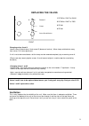
  • Page 9: Replacing The Valves

    Replacing the valves 9 1 2 3 4 screw b and washer clamp 1 ecc82 or 12au7 or 5814a screw a 2 ecc83 or 12ax7 or 7025 3 pcl86 4 pcl86 front changing valves 3 and 4 loosen screw a (break glue). Undo screw b (beware of washer). Move clamp anticlockwise away from valves. Pull valves gently out. If unit is...