Accucraft FLYING SCOTSMAN Operating Instructions Manual

Summary of FLYING SCOTSMAN

  • Page 1

    1 accucraft uk ltd unit 4, long meadow industrial estate, pontrilas, herefordshire. Hr2 0ua tel: 01981 241380 www.Accucraft.Uk.Com operating instructions “flying scotsman” safety first all our locomotives are safe to run, and will give many hours of pleasure, providing the following safety procedure...

  • Page 2: General Hints

    2 general hints as with all operating machinery, whether model or full size, wear will occur. In the model steam locomotive much can be done to help prolong its life and decrease the amount of time required in the workshop for servicing. Keep the engine as clean as possible, and the motion free from...

  • Page 3: Preparation For Running

    3 the axle pump by-pass valve is in the cab on the right hand side. See photo. To open the valve turn anti-clockwise. The direction control is the lever in the nearside of the cab. To operate pull gently outwards and move to the desired direction. The control is “gated”, and will therefore hold itse...

  • Page 4: Lighting Up

    4 the filler cap off for the present, so that any trapped air can escape. It can be refitted after you have filled up the boiler. To fill the boiler: using the long brass lever supplied, fit it onto the the hand pump in the tender and fill up the boiler to about ¾ full; this will allow a good space ...

  • Page 5

    5 condensate has been ejected. Do not stand over the chimney as ejected boiling water/steam could cause serious scalding. Place the direction lever into the reverse position, and then open the main steam throttle valve. The engine should start to move off in the reverse direction. When starting from...

  • Page 6: End Of Run

    6 end of run when the last run has finished the locomotive should be allowed to cool. When cool, clean the engine, check the motion and oil if necessary. The locomotive should always be put away in a clean condition as it attracts less dust and is always ready for the next run (or to be shown to an ...

  • Page 7: Tools Supplied:

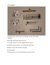
    7 tools supplied: a: name plates, these slip on over the lugs on the centre wheel splashers. B: tender hand pump extension lever. C: large syringe, not really required for this model. D: small syringe and tube, for draining the lubricator. E: bag of spare bolts and hex wrenches. F: nut spinners. G: ...

  • Page 8: Tender Parts:

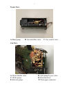
    8 tender parts: a: hand pump. B: gas tank filler valve. C: gas control valve. Cab parts: a: steam throttle valve. B: axle pump by-pass valve. C: water gauge. D: direction lever. E: pressure gauge. F: water pipe connectors..