Bastl tromso Assembly Manual

Summary of tromso

  • Page 1

    Last update: 9. 9. 2016 tromsØ v1.0 - assembly guide bastl-instruments.Com introduction this guide is for building tromsø module from bastl instruments. It is good to have basic soldering skills and to be able to identify electronic components before starting this kit. However if you have never sold...

  • Page 2

    Before starting this kit, prepare the following tools: ● soldering iron (15-20w) ● multi-meter ● flush cutters ● n2. Hex screwdriver or allen key (enclosed with kit) ● phillips screwdriver ● wrench no. 8 ● protective eyewear after the tromsø is built it should be calibrated. You can use your mobile ...

  • Page 3

    Now you can move to soldering the ic sockets (be aware of the right direction, there is a notch on the sockets that has to match with the sign on pcb): - 8 pin dil​ (1x) - 14 pin dil​ (2x) - 16 pin dil​ (1x) now let’s do some ​capacitors​. According to the size insert and solder them in the followin...

  • Page 4

    Then you can solder the ​fuses​. There are just two of them. ​they look quite similar to a ceramic capacitors. Place them in the “ptc” rectangular). To finish soldering of the bottom board you have to connect the female headers with the male headers from the top board bag. Use your flush cutters to ...

  • Page 5

    Great, you are done now with the bottom board! Before moving to the next one make the last check that all parts are on the right place and every joint is properly soldered. Top board now let’s do the top pcb. Again, start with the ​resistors​: - 1k​ (2x), ​33k​ (1x), ​39k​ (1x), ​100k​ (3x) then ins...

  • Page 6

    Then turn the unit facing with pcb upwards. Make sure that everything is properly aligned. Push the switches ​and ​led ​to be sure that they come through the panel. Now you are finally ready to solder all these inserted parts. Final assembly congratulations! You have made it through. Now just connec...

  • Page 7

    Use triangle output and amplify it yo so can hear it. Flip all the switches up. Set vco rate and threshold at twelve o'clock (as precisely as possible) and turn the attenuator at full. Now turn on your tuner and adjust the trimmer until you will measure 240 hz and that’s it! This process is approxim...

  • Page 8

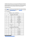
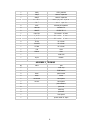
    1 220k r-eu_0204/5 2 100pf ceramic capacitor 1 560pf ceramic capacitor 1 47nf/63v wima polyester capacitor 11 100nf ceramic capacitor 2 10uf electrolytic capacitor 2 1n4148 diode-d-5 2 1n4007 diode-d-7.5 1 8 pin dil dil socket - in foam 2 14 pin dil dil socket - in foam 1 16 pin dil dil socket - in ...