- DL manuals
- Federal Signal Corporation
- Switch
- MS4000
- Installation And Operating Instructions Manual
Federal Signal Corporation MS4000 Installation And Operating Instructions Manual
ASAP Service and Maintenance Manual
ASAP Installed Systems
Maintenance: 3-47
Charging Air Force: 3-6
Charging System with Battery Brain and No Generator:7-10
Charging System with Battery Brain and Generator without Push Button: 11-15
Charging System with Battery Brain and Generator: 16-20
Charging System without Load Manager: 21-24
Dropping the Generator: 25-26
Getting to the Drive Belt: 27-28
Getting to the Drive Belt New Style: 29-31
Removing Blue Power Steering Wire: 32-33
Removing Load Manager (Wiring Schematic): 34
Rewinding the Roll-Up Door: 35-36
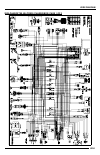
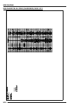
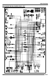
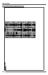
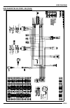
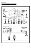
Wiring Diagrams: 37-47
Component Manuals: 48
Battery Brain: 48-55
Blizzard Wizard: 56-59
Curtis Cab: 60-69
Darley Davey Pump: 70-89
Dual Pro Charger: 90-96
Dometic Climate Control: 97-105
Federal Signal: 106-128
Electra Steer: 129-140
Hannay Hose Reel: 141-147
Honda Pump Engine: 148-167
Pro Tournament Battery Charger: 168-176
1
Summary of MS4000
Page 1
Asap service and maintenance manual asap installed systems maintenance: 3-47 charging air force: 3-6 charging system with battery brain and no generator:7-10 charging system with battery brain and generator without push button: 11-15 charging system with battery brain and generator: 16-20 charging s...
Page 2
Warn winch: 177-208 whelen lightbar: 209-211 polaris chassis: 174-672 polaris owner’s manual: 212-348 polaris service manual: 349-708 2.
Page 3: Charging Air Force
Charging air force introduction the asap has two batteries, one battery is located under the hood. This battery is for the polaris ranger functions. This battery starts the engine, runs the ignition system, headlights, turn signals, power steering system and aux. Cooling fan. This battery is for all...
Page 4
The polaris battery is located under the hood and the steel solenoid is located near this battery. This battery size is considered a cb30l-b . Always replace it with one that is equivalent. Deep cycle battery: the deep cycle battery is charged only one way: 1. Onboard battery charger if the shorelin...
Page 5
The deep cycle battery is located under the driver. Its size is considered a group 27 . When replacing this battery always replace it with a group 27 deep cycle battery. This battery needs to be charged daily to prevent discharge. If the deep cycle battery gets discharged completely (less than 2 vol...
Page 6
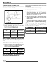
The following picture shows the charging status. Notice that even with three red lights on, the battery has 14.0 volts in it. That’s still a pretty good battery. If the battery was completely dead, it will take at least 8 hours to recharge the deep cycle battery up to a full charge status. Shoreline...
Page 7: Generator
Charging system with battery brain and no generator introduction the asap has two batteries, one battery is located under the hood. This battery is for the polaris ranger functions. This battery starts the engine, run’s the ignition system, headlights, turn signals, power steering system and (option...
Page 8
Deep cycle battery: the deep cycle battery is charged only one way: 1. Onboard battery charger if the shoreline is plugged in, the onboard battery charger charges the battery. The deep cycle battery is located under the driver. Its size is considered a group 27 . When replacing this battery always r...
Page 9
If you find yourself in an emergency situation and your deep cycle battery drops below the 10.5 volts which will cut or turn off all auxiliary power you can push the push button on the dash near the windshield to regain 12 volt battery power. At that point you are running on only the remaining batte...
Page 10
10
Page 11
Charging system with battery brain and generator without push button introduction the asap has two batteries, one battery is located under the hood. This battery is for the polaris ranger functions. This battery starts the engine, runs the ignition system, headlights, turn signals, power steering sy...
Page 12
The polaris battery is located under the hood and the steel solenoid is located near this battery. This battery size is considered a cb30l-b . Always replace it with one that is equivalent. Deep cycle battery: the deep cycle battery is charged only one way: 1. By the onboard battery charger if the s...
Page 13
A quick way to determine what is connected to the deep cycle battery is to turn off the master switch that is located between the driver’s legs. This switch runs everything that is connected to the deep cycle battery. So if you’re not sure, turn that item in question “on” and then turn the master sw...
Page 14
The deep cycle battery has a load manager device that monitors the battery voltage at all times. As long as the battery voltage is above 10.5 volts the green light is illuminated on the dash indicating the battery voltage is in an okay status. If the voltage drops below 10.5 volts the green light wi...
Page 15
15.
Page 16: Generator
Charging system with battery brain and generator introduction the asap has two batteries, one battery is located under the hood. This battery is for the polaris ranger functions. This battery starts the engine, runs the ignition system, headlights, turn signals, power steering system and (optional) ...
Page 17
The polaris battery is located under the hood and the steel solenoid is located near this battery. This battery size is considered a cb30l-b . Always replace it with one that is equivalent. Deep cycle battery: the deep cycle battery is charged only one way: 1. Onboard battery charger if the shorelin...
Page 18
The deep cycle battery is located under the driver. Its size is considered a group 27 . When replacing this battery always replace it with a group 27 deep cycle battery. This battery needs to be charged daily to prevent discharge. The deep cycle battery has a load manager device that monitors the ba...
Page 19
Necessary. It would be better to start the generator which would turn on the on board battery charger. Note: you might find yourself in a situation where you have the master switch in the on position, the ignition key in the on position and the green light is not on but you know that the deep cycle ...
Page 20
Shoreline location: the shoreline is located near the driver’s door. 20
Page 21
Charging system without load manager introduction the asap has two batteries, one battery is located under the hood. This battery is for the polaris ranger functions. This battery starts the engine, runs the ignition system, headlights, turn signals, power steering system and aux. Cooling fan. This ...
Page 22
The polaris battery is located under the hood and the steel solenoid is located near this battery. This battery size is considered a cb30l-b . Always replace it with one that is equivalent. Deep cycle battery: the deep cycle battery is charged only one way: 1. Onboard battery charger if the shorelin...
Page 23
The deep cycle battery is located under the driver. Its size is considered a group 27 . When replacing this battery always replace it with a group 27 deep cycle battery. This battery needs to be charged daily to prevent discharge. If the deep cycle battery gets discharged completely (less than 2 vol...
Page 24
The following picture shows the charging status. Notice that even with three red lights on, the battery has 14.0 volts in it. That’s still a pretty good battery. If the battery was completely dead, it will take at least 8 hours to recharge the deep cycle battery up to a full charge status. Shoreline...
Page 25: Dropping The Generator
Dropping the generator 1. Place jack under generator 2. Remove the four bolts holding the generator to the frame. 3. There are a bundle of cables located in the top of the frame. They are looped so that the generator can be lowered down some what in order for the connections to the generator to be u...
Page 26
4. There will be three plugs that will need to be unplugged (see above) along with the fuel line. The fuel line will need to have the hose clamp removed at the generator. 26.
Page 27
Step 1: open the driver’s side lower storage compartment and loosen the six bolts that are in the top of the box. Then pull the compartment towards you. It will slide out and come completely off the unit. (some of the earlier units may require you to remove the six bolts completely in order to remov...
Page 28
Step 3: the drive belt is located behind the cover shown here in this photo. There are a row of bolts holding the cover on. See photo below remove all of the bolts and pull the cover off the reveal the drive belt. 28.
Page 29
Step 1: open the driver’s side lower storage compartment and remove the six bolts that are in the top of the box. Then pull the compartment out and completely off the unit. Step 2: now remove the black plastic panel that is beside the deep cycle battery. It takes a 7mm socket to remove the four scre...
Page 30
Step 3: the drive belt is located behind the cover shown here in this photo. There are a row of bolts holding the cover on. See photo below remove all of the bolts and pull the cover off the reveal the drive belt. Your unit has a high performance drive belt and clutch installed in it. It is not the ...
Page 31
31.
Page 32
You will need to switch out the power steering module. After you switch them out, there is a blue wire coming out of the module. If the blue wire is only 4-5 inches long like in the photo below that is good. If the blue wire continues on you will need to proceed with this procedure. Go back an inch ...
Page 33
Coil pack the other end of the blue wire is tapped into the green\white wire coming out of the coil pack. I would like for you to cut the wire here also and retape the green\white wire. By doing this, it will eliminate any corruption that the coil may be seeing in that line that was running up to th...
Page 34
34.
Page 35
Rewinding the rear roll up door barrel find the decal on the barrel that indicates the number of factory preset turns of the barrel. Then find the box that indicates the number that the barrel can be turned additionally. (this one in the photo can be turned a total of 16 times.) find your numbers an...
Page 36
36.
Page 37
37.
Page 38
38.
Page 39
39.
Page 40
40
Page 41
41.
Page 42
42.
Page 43
43.
Page 44
44.
Page 45
45.
Page 46
46.
Page 47
47.
Page 48
48.
Page 49: Installation Instructions
Installation instructions battery brain is an innovative accessory that easily installs to any battery. Using unique micro-electronic technology it continually monitors the battery power. When battery brain detects power falling below the level required to start your engine, it automatically isolate...
Page 50
Technical specifi cations dimensions base 1 5/8” (4cm) x 2 1/4” (5.5cm), height (including removable protective cap) 2 1/2” (6cm), brackets 1 1/4” (3.5cm) x 5/8” (1.5cm) x 1/8” (3mm). Weight battery brain 175gm, accessories 280gm, packaging 3gm; total weight 408gm (1lb). Current specifications opera...
Page 51
Optional: vibration sensor - available separately, can be used in place of the engine on wire *(see your retailer for details) l-bracket & straight mounting brackets remote control (type ii & iii models only) remote control frequency: tx433.92 mhz battery type: 12 v 27 a (the batteries are already i...
Page 52
Installation instructions note: battery location and position differ in vehicles. With the supplied accessories you can mount the battery brain on the vehicle using the top mount, side mount or chassis mount positions. Note: after installation ensure all connections are tight. Ensure manual reset co...
Page 53
Step 4: install black engine on wire. Installation of the engine on wire will prevent the battery brain from disconnecting the battery while the engine is running. This will also prevent the battery brain from disconnecting the battery if the voltage level drops below 11.8v as could be the case with...
Page 54
Testing the installation a) to test for successful installation: start the engine after installation is complete. If the engine starts properly proceed to the next step. If not, review the installation instruction or consult a certifi ed technician. B) to test battery brain operation: with the manua...
Page 55
Battery brain is an innovative accessory that easily installs to any battery. Using unique micro-electronic technology it continually monitors the battery power. When battery brain detects power falling below the level required to start your engine, it automatically isolates the battery from the ele...
Page 56
56.
Page 57
57.
Page 58
58.
Page 59
59.
Page 60
Inst alla tion & owner’s manual to install this cab kit (p/n 2874660), you will need mount kit p/n 2874689. Cab installation instructions polaris ranger/utv cab kit (p/n 2874660) exposure to carbon monoxide can cause illness, serious injury or death. Never operate vehicle if suspicious of carbon mon...
Page 61
Cab installation before you start helpful reminders: a. Leave all bolts loose for later adjustment unless otherwise specified. B. Read and understand all instructions before beginning. C. Plastic washers have been supplied to provide a weather seal around all exterior fasteners. The plastic washer s...
Page 62
Model: polaris ranger cab kit installation instructions 1. Vehicle prep. 1.1 remove the roll bar from the vehicle so the vehicle appears as shown in fig- ure 1.1. 1.2 remove the seat back (the actual back portion of the seat) from the roll bar tubing as shown in fig. 1.2. Save these eight (8) bolts ...
Page 63
Model: polaris ranger cab kit installation instructions 3. Rear panel (cont’d.) 3.3 place the rear panel assembly on the vehicle as shown in fig. 3.3. (note: the bottom of the rear panel is to remain in front of the four (4) welded tubes as shown in fig. 3.3.1) (note: a cut will need to be made in t...
Page 64
Model: polaris ranger cab kit installation instructions rev. J 8. Windshield 8.1 with assistance, install the windshield to the windshield support (see fig- ure 8.1). Use six (6) 5/16 x 1 3/4” long flat head screws and 3/4” thick plas- tic spacer blocks (placed between the plastic hinge and the wind...
Page 65
Model: polaris ranger cab kit installation instructions rev. J 11. Mounting bracket 11.1 lift the dump bed. 11.2 using a 13/32” drill bit, and using the approximate center of the mounting bracket slots as a guide, drill four (4) holes through the sheet metal on the ve- hicle as shown in the enlarged...
Page 66
Rev. J page 7 of 7 1 utv-03 club car white color to be: reflectors polaris main cab body - ranger / utv (p/n 2874660) qty. P/n right hinge *in house applications * (round) 1" bulb hinge pin right * 1 right utv-09r 1 left utv-09l qty. P/n unitized side frames pin left * * 5/8" bulb 3" bulb (flat) 5/8...
Page 67
Inst alla tion & owner’s manual the contents of this envelope are the property of the owner. Be sure to leave with the owner when installation is complete. Door installation instructions polaris ranger/utv steel doors (p/n 2875941-067) exposure to carbon monoxide can cause illness, serious injury or...
Page 68
Polaris ranger/utv door kit (steel doors) installation instructions rev. - tools required: 1. Rear mounts 1.1 remove existing rear mounts (part number 2874689) from the cab rear panel and install left and right mounts from this kit in their place as shown in figure 1.1. 2. Doors 2.1 install doors on...
Page 69
69.
Page 70
7ak306/5213he/npt 2 stage 13 hp honda 1 70
Page 71
7ak306/5213he/npt 2 stage 13 hp honda 2 71.
Page 72
7ak306/5213he/npt 2 stage 13 hp honda 3 72.
Page 73
7ak306/5213he/npt 2 stage 13 hp honda 4 73.
Page 74
7ak306/5213he/npt 2 stage 13 hp honda 5 74.
Page 75
7ak306/5213he/npt 2 stage 13 hp honda 6 75.
Page 76
7ak306/5213he/npt 2 stage 13 hp honda 7 part # description/ price davey prod. Notes code 3822201 discharge gasket/ $13.64 5320902 valve flap assembly/ $41.37 ke00509 spark arrestor kit/ $62.24 2904820 impeller 1 st stage/ $89.81 sold as set – top part #2904801 davey part #13381 & bottom part #290482...
Page 77
Two stage 5 series work instructions 1 77.
Page 78
Two stage 5 series work instructions 2 78.
Page 79
Two stage 5 series work instructions 3 79.
Page 80
Two stage 5 series work instructions 4 80
Page 81
Two stage 5 series work instructions 5 81.
Page 82
Two stage 5 series work instructions 6 82.
Page 83
Two stage 5 series work instructions 7 83.
Page 84
Two stage 5 series work instructions 8 84.
Page 85
Two stage 5 series work instructions 9 85.
Page 86
Two stage 5 series work instructions 10 86.
Page 87
Two stage 5 series work instructions 11 87.
Page 88
88.
Page 89: Limited Three-Year Warranty
Limited three-year warranty air conditioners & heat pumps the seller named below makes the following warranty with respect to the dometic product: 1. This warranty is made only to the first purchaser (herein after referred to as the “original purchaser”) who acquires the product for his own use and ...
Page 90
90
Page 91
91.
Page 92
92.
Page 93
93.
Page 94
94.
Page 95
95.
Page 96
96.
Page 97
97.
Page 98
98.
Page 99
99.
Page 100
100
Page 101
101.
Page 102
102.
Page 103
103.
Page 104
104.
Page 105: Limited Three-Year Warranty
Limited three-year warranty air conditioners & heat pumps the seller named below makes the following warranty with respect to the dometic product: 1. This warranty is made only to the first purchaser (herein after referred to as the “original purchaser”) who acquires the product for his own use and ...
Page 106
Safety message to installers of siren speakers people’s lives depend on your proper installation and servicing of federal signal products. It is important to read and follow all instructions shipped with this product and the original product. Listed below are some other important safety instructions...
Page 107
2 es100, es100-deu, and es100-uni 100 watt speakers • be sure the siren amplifier and speaker(s) in your installation have compatible wattage ratings. • in order for the electronic siren to function properly, the ground connection must be made to the negative battery terminal. • sound output will be...
Page 108
Es100, es100-deu, and es100-uni 100 watt speakers 3 unpacking the kit after unpacking the kit, inspect it for damage that may have occurred in transit. If it has been damaged, do not install it. File a claim immediately with the carrier, stating the extent of damage. Carefully check all envelopes, s...
Page 109
4 es100, es100-deu, and es100-uni 100 watt speakers wiring the speaker important: the es100 series speakers comply with the requirements of sae j1849 evs3 and ccr title 13 class a when they are used with federal signal corporation electronic sirens. The es100 series speaker includes the three models...
Page 110
Es100, es100-deu, and es100-uni 100 watt speakers 5 after the installation, test the siren system to ensure that it is operating properly. Also test all vehicle functions, including horn operation, vehicle safety functions, and vehicle lighting systems to insure proper operation. Ensure that the ins...
Page 111
6 es100, es100-deu, and es100-uni 100 watt speakers • although your warning system is operating properly, it may not alert everyone. People may not hear, see, or heed your warning signal. You must recognize this fact and continue driving cautiously. • situations may occur which obstruct your warning...
Page 112
Es100, es100-deu, and es100-uni 100 watt speakers 7 • your federal signal customer or account number. • the purchase order number under which the items were purchased. • the shipping method. • the model or part number of the product being returned. • the quantity of products being returned. • drop s...
Page 113
2645 federal signal drive, university park, il 60466-3195 tel.: (800) 264-3578 • fax: (800) 682-8022 www.Fedsig.Com © 2009 federal signal corporation 113.
Page 114: Installation and Operating
Installation and operating instructions ms4000/ms4000u mini-siren man – ms4000 install rev: 1/26/01 255331b 114.
Page 115
I 115.
Page 116
I general description ..............….........… 1 ii specifications ....................................… 2 iii safety message to installers................ 3 iv installation……………………................ 4 v safety message to operators.............. 8 vi operation……………………….……….. 9 vii safety message for ...
Page 117: Section I
Section i general description page 1 the federal signal ms4000 siren series is an advanced, efficient, and economical mini-siren. It offers value packed performance for those who do not require a full-featured siren. It provides wail, yelp, priority, manual siren and air horn functions. This siren s...
Page 118: Section II
Section ii specifications page 2 input voltage 9 vdc to 15 vdc input current, operating 10 amps max polarity negative grounded systems only standby current 60ma nominal operating temperature range -30 ° c to +65 ° c frequency ranges 725 to 1575 hz cycle range wail 12 cycles/min yelp 240 cycles/min m...
Page 119: Section III
Section iii safety message to installers of federal signal light and sound systems page 3 warning the lives of people depend on your safe instal- lation and servicing of federal products. It is important to read and follow all instructions shipped with the products. In addition, listed below are som...
Page 120: Section Iv
Section iv installation page 4 4-1 inspection of unit after unpacking the ms4000 series siren, examine it for damage that may have occurred in transit. If the equipment has been damaged, file a claim immediately with the carrier stating the extent of damage. Carefully check all envelopes, shipping l...
Page 121
Page 5 c. Secure the mounting brackets to the dash with (4 each unsupplied) 10-32 x 3/4 hex head screws, 10- 32 split lock washers and 10-32 hex nuts. D. Secure the electronic siren to the mounting brackets with 1/4” self tapping machine screws and 3/8-id” internal tooth washers (supplied). E. Tilt ...
Page 122
A. Speaker. The unit is designed to operate with one 11- ohm impedance speaker. A speaker is not included as part of the electronic siren. Federal speakers are weatherproof and may be installed in any convenient location; on the fender, behind the grill, etc. Any special mounting instructions applic...
Page 123
C. Power connections. The ms4000 siren series can operate from any 12-volt negative ground vehicle electrical system. Therefore, before making any electrical connections, determine the polarity of the vehicle electrical system ground. Caution the ms4000 series sirens do not have an on- off switch. I...
Page 124: Section V
Section v safety message to operators of federal signal light/sound systems page 8 warning the lives of people depend on your safe operation of federal products. It is important to read and follow all instructions shipped with the products. In addition, listed below are some other important safety i...
Page 125: Section Vi
Section vi operation page 9 6-1 general all controls utilized during normal operation of the ms4000 are located on the front panel (see figure 6-1) or on the remote switch panel for the ms4000u. Two rocker switches operate the siren. The horn/manual switch provides a momentary action while the wail/...
Page 126: Section Vii
Section vii safety message to personnel servicing federal signal electronic sirens page 10 warning the lives of people depend on your safe servicing of products. It is important to read and follow all instructions shipped with the products. In addition, listed below are some other safety instruction...
Page 127: Section Viii
Section viii service page 11 the factory can and will service your equipment or assist you with technical problems that cannot be handled satisfactorily and promptly locally. Servicing, other than cosmetic features, should be performed by a qualified federal signal service center. If the unit is not...
Page 128: Section Ix
Section ix priority sound elimination ms4000/ms4000u page 12 for agencies that operate in areas where the priority sounds are not authorized we are providing a shunt to be placed on the circuit board at location jmp1. If the end user installs this shunt, the unit will not produce the priority sounds...
Page 129: Kit Number 8051440
Electra electra - - steer™ steer™ kit number 8051440 polaris electric steering installation manual thank you for purchasing our electra-steer™ 12v electric assist power steering system. Please carefully read this instruction sheet entirely before you begin to install the system. Remember, before beg...
Page 130
Full refund will not be granted to any kits that are damaged, scratched, or altered in any fashion. Installation tips: due to minor variations in vehicle frames, we recommend that you leave all the u-joint pinch bolts loose until the motor is mounted. Then rock the steering wheel back and forth to a...
Page 131
Removal of existing shaft assembly: 1. Remove center cap from steering wheel & remove the 15/16” nut from steering wheel. Have a second person carefully tap on the upper shaft while you pull up on the wheel to remove it from the taper on the shaft. Be sure not to loose the two wave washers & flat wa...
Page 132
2. Put the bracket on the underside of the frame and install a 3/8 bolt from the bottom side of the bracket and install the lock washer and nut on the topside and snug but leave loose. 3. The bracket must be flush on the bottom and side. When the bracket is secure on the frame, using the hole in the...
Page 133
4. When you have your motor hanging in place, you can install the lower shaft assy. 5. When installing the lower shaft it is necessary to put the pinion side (rack side) of the shaft on first. Once you have the pinion side on and in place you will have to wiggle the motor & shaft together to allow c...
Page 134
6. You may now torque the bracket bolts to 30 ft lbs. 7. To install the upper shaft, you have to fish the shaft through the column frame and slide the shaft onto the spline of the motor. The steering wheel shaft can then get dropped down through the column and splined onto the u-joint at the top. In...
Page 135
10. The module wiring is described in the schematic supplied. The white wire gets a single spade terminal. The purple or brown wire also gets a spade terminal. Note: these two wires are used for trouble code reading and clearing. They need to be located in an accessible place. They do not get connec...
Page 136
11. The led needs to be mounted in the dash where it is visible. To install the light it’s a simple matter of drilling a ½ inch hole and snapping the light into place from the front side. Note: pay special attention to what is behind your dash before drilling a hole. 12. Once your connections have b...
Page 137
2. To locate where your pilot hole should be, you need to stand outside the vehicle with the hood open, facing the firewall. 3. With a tape measure, measure from the left side of the brake pedal mounting bracket over 2-7/8” mark the center of the frame channel. This is where you drill a 3/8” hole. A...
Page 138
In some cases the purple above wire may be substituted for a brown wire!! The electra-steer™power steering assist unit is intended to be used in accordance with all safety recommendations of the original manufacturer of the vehicle as specified in the owners manual. This product is intended for norm...
Page 139
Electra steer diagnosis trouble code reading and code clearing 1. Verify that your trouble code light is on steady. 2. Peel back a small portion of the orange trouble code light wire to expose the copper portion of it. 3. Next use a jumper wire and go from the purple wire with the single spade conne...
Page 140
(12/18/07) 140
Page 141: Iso 84
5m hp 5-08 form h-8400-1˝-p rev. 4 hannay reels, inc., 553 state route 143 westerlo, ny 12193 telephone 518-797-3791 fax 1-800-reeling (733-5464) int’l fax (518) 797-3259 website: www.Hannay.Com e-mail: reels@hannay.Com iso 84 parts list 1˝ hose reel hannay iso parts lists are available at www.Hanna...
Page 142: Part Number
Parts list iso 84 1˝ hose reels item no. Description part number quantity 1 drum, 10-1/2˝ diameter ............................................................(specify model) 9905.3131 1 2 front disc, 19-20 series ...........................................................(specify model) 9903.0821 1...
Page 143: Safety
Safety guidelines read this first. These guidelines provide general safety recom- mendations for using hose and cable reels. However, the employer should assess and determine if any additional safety measures are required for its particular applica- tion and operation, and fully instruct employees o...
Page 144: Consignes
Consignes de sÉcuritÉ À lire en premier. Ces instructions donnent des recommandations générales de sécurité pour l’utilisation d’enrouleurs de câble et de flexible. Mais c’est à l’employeur qu’il revient d’évaluer et de déterminer s’il est nécessaire d’adopter des mesures de sécurité supplémentaires...
Page 145: Veiligheidsvoorschriften
Veiligheidsvoorschriften lees dit eerst. Deze voorschriften zijn algemene veiligheidsinstruc- ties voor het uitpakken en toepassen van slang- en kabelhaspels. De werkgever dient te beoordelen of extra veiligheidsmaatregelen noodzakelijk zijn voor een specifieke toepassing en dientengevolge de werkne...
Page 146: Directrices De
Directrices de seguridad rogamos leer primero. Estas directrices proporcionan las recomenda- ciones generales de seguridad para la utilización de los carretes para mangueras y cables. Sin embargo, el empleador debe estudiar y determinar si se requiere alguna medida de seguridad adicional para su apl...
Page 147: Richtlinien
Richtlinien zur sicherheit wichtige informationen, unbedingt lesen! Diese richtlinien geben allgemeine sicherheitsempfehlungen zum einsatz von schlauch- und kabeltrommeln. Es ist jedoch von fall zu fall zu prüfen und festzulegen, ob weitere sicherheitsmaßnahmen für die jeweilige anwendung und den be...
Page 148
G o p r e p a r e d ™ 15 warn industries • the basic guide to winching techniques g o p r e p a r e d ™ 14 warn industries • the basic guide to winching techniques as you probably have already noticed, there are many things to do and consider before you actually begin pulling. Think through what you...
Page 149
Step 13: make your intentions clear. Be sure that everyone in the immediate vicinity surrounding the winching operation is completely aware of your intentions before you pull. Declare where the spectators should not stand — never behind or in front of the vehicle and never near the rope or snatch bl...
Page 150
G o p r e p a r e d ™ 19 warn industries • the basic guide to winching techniques g o p r e p a r e d ™ 18 warn industries • the basic guide to winching techniques • inspect the rope before and after each winching operation. If the rope has become kinked or frayed, the rope needs to be replaced imme...
Page 151
Le manuel de base des techniques de treuillage warn industries off-road products 12900 s.E. Capps road clackamas, or 97015-8903 usa service à la clientèle : 1-800-543-warn fax : 1-503-722-3000 www.Warn.Com table des matiÈres mesures générales de sécurité. . . . . . . . . . . . . . . . . . . . . . . ...
Page 152
G o p r e p a r e d ™ 23 warn industries • le manuel de base des techniques de treuillage les directives suivantes comprennent des indications intitulées avertissement, attention, avis et remarque. Chacune a un objectif bien précis : avertissement présente des consignes de sécurité soulignant un dan...
Page 153
G o p r e p a r e d ™ 25 warn industries • le manuel de base des techniques de treuillage g o p r e p a r e d ™ 24 warn industries • le manuel de base des techniques de treuillage at t e n t i o n danger de happement par des piÈces mobiles le non-respect des instructions peut entraîner des blessures...
Page 154
4 1 5 2 6 3 7 8 donnÉes essentielles sur le treuil Électrique g o p r e p a r e d ™ 27 warn industries • le manuel de base des techniques de treuillage pour commencer, vous devez vous familiariser avec le treuil warn et chacun de ses composants : entraînez-vous avec le treuil avant de l'utiliser sur...
Page 155
Accessoires de treuillage utiles g o p r e p a r e d ™ 29 warn industries • le manuel de base des techniques de treuillage seul , le treuil n'est guère plus qu'un simple outil. Mais utilisé conjointement avec un certain nombre d'accessoires, votre treuil warn devient un outil polyvalent extrêmement ...
Page 156
G o p r e p a r e d ™ 31 warn industries • le manuel de base des techniques de treuillage g o p r e p a r e d ™ 30 warn industries • le manuel de base des techniques de treuillage sangle de dépannage n’utilisez jamais de sangles de dépannage dans une opération de treuillage. Parce qu'elles sont conç...
Page 157
Avant de treuiller g o p r e p a r e d ™ 33 warn industries • le manuel de base des techniques de treuillage g o p r e p a r e d ™ 32 warn industries • le manuel de base des techniques de treuillage Étape 4 : tirez le cble jusqu'au point d'ancrage. Tirez suffisamment de câble pour atteindre le point...
Page 158
Étape 7 : bloquez l’embrayage. Bloquez le tambour du treuil en faisant pivoter le levier de l'embrayage sur le treuil en position « embrayage ». Étape 8 : connectez la tÉlÉcommande (si vous en avez une). Faites attention à ne pas laisser le cordon de la télécommande pendre devant le treuil. Déconnec...
Page 159
G o p r e p a r e d ™ 37 warn industries • le manuel de base des techniques de treuillage g o p r e p a r e d ™ 36 warn industries • le manuel de base des techniques de treuillage Étape 17 : dÉconnectez le cble. Décrochez le câble du point d'ancrage. Étape 18 : rembobinez le cble. La personne qui s'...
Page 160
En derniÈre analyse maintenance g o p r e p a r e d ™ 38 warn industries • le manuel de base des techniques de treuillage • inspectez, le cas échéant, la télécommande au cas où elle serait endommagée. Assurez-vous de bien couvrir la prise de télécommande pour éviter que la poussière et la saleté ne ...
Page 161
Guía básica de técnicas para el uso del cabrestante productos off-road de warn industries 12900 s.E. Capps road clackamas, or 97015-8903 (ee.Uu.) servicio al cliente: 1-800-543-warn fax: 1-503-722-3000 www.Warn.Com Índice: precauciones generales de seguridad . . . . . . . . . . . . . . . . . . . . ....
Page 162
G o p r e p a r e d ™ 43 warn industries • guÍa bÁsica de tÉcnicas para el uso del cabrestante al leer estas instrucciones, verá advertencias, precauciones, avisos y notas. Cada mensaje tiene un propósito específico. Las advertencias son mensajes de seguridad que indican que está ante una situación ...
Page 163
G o p r e p a r e d ™ 45 warn industries • guÍa bÁsica de tÉcnicas para el uso del cabrestante g o p r e p a r e d ™ 44 warn industries • guÍa bÁsica de tÉcnicas para el uso del cabrestante precauciÓn peligro de enredarse en las piezas mÓviles de no seguirse estas instrucciones, podrían producirse l...
Page 164
4 1 5 2 6 3 7 8 lo fundamental del cabrestante elÉctrico g o p r e p a r e d ™ 47 warn industries • guÍa bÁsica de tÉcnicas para el uso del cabrestante para comenzar, debe familiarizarse con el cabrestante warn y con cada uno de sus componentes: practique el uso del cabrestante antes de utilizarlo. ...
Page 165
Los accesorios del cabrestante que necesitarÁ g o p r e p a r e d ™ 49 warn industries • guÍa bÁsica de tÉcnicas para el uso del cabrestante guantes . Con el uso, el cable llegará a tener “púas” que pueden cortar la piel. Es extremadamente importante llevar guantes protectores mientras el cabrestant...
Page 166
G o p r e p a r e d ™ 51 warn industries • guÍa bÁsica de tÉcnicas para el uso del cabrestante g o p r e p a r e d ™ 50 warn industries • guÍa bÁsica de tÉcnicas para el uso del cabrestante correa de recuperación . Nunca utilice una correa de recuperación durante el funcionamiento del cabrestante. C...
Page 167
Antes de usar el cabrestante tracción con cable sencillo maniobrado para la tracción las siguientes fases describen cómo recuperar su vehículo utilizando tracción con cable sencillo. Las técnicas de maniobrado de cable doble o múltiple siguen el mismo proceso pero utilizan una polea para realizar la...
Page 168
Fase 7: bloqueo del embrague. Bloquee el tambor del cabrestante girando la palanca del embrague para embragar. Fase 8: conecte el control remoto (si viene incluido). Tenga cuidado de que el cable del control remoto no se enrede enfrente del cabrestante. Desconecte siempre el control remoto cuando no...
Page 169
Fase 13: avise de sus intenciones. Asegúrese de que todas las personas que estén en las inmediaciones del cabrestante que se vaya a poner en uso sepan bien las intenciones que usted tiene antes de comenzar la tracción. Ponga límites en cuanto al lugar donde los espectadores deben estar—nunca detrás ...
Page 170
El anÁlisis final mantenimiento g o p r e p a r e d ™ 58 warn industries • guÍa bÁsica de tÉcnicas para el uso del cabrestante • inspeccione el control remoto, si lo tuviera, para cerciorarse de que no esté dañado. Asegúrese de cubrir el control remoto para evitar que entre suciedad en las conexione...
Page 171: Automotive:
Page 1 installation guide: dominator™ lightbar (with end flashers) model(s): d2**, d4****, d6******, d8***** ©2004 whelen engineering company inc. Form no.13897e (052009) ® engineering company inc. 51 winthrop road chester, connecticut 06412-0684 phone: (860) 526-9504 fax: (860) 526-4078 internet: w...
Page 172
Page 2 driver side example: two, 2-light dominators™ mounted on the rear deck. Phase 1 / alt phase 2 / alt phase 1 / sim phase 2 / sim passenger side phase 1 / alt phase 1 / sim phase 1 / sim phase 1 / alt gry (sync) wht/vio (scan-lock) blk (ground) blk (ground) red (+12vdc/fuse @ 5a) red (+12vdc/fu...
Page 173
Page 3 1 1 1 1 1 a/r a/r a/r a/r a/r a/r 9 7 a/r a/r a/r 3 a/r a/r 1 a/r a/r a/r a/r a/r 1 1 1 1 1 1 1 1 1 2 2 1 1 4 4 1 1 2 1 4 2 1 4 2 2 2 2 2 2 2 2 2 2 2 2 2 2 2 2 11 - 2 6 3 7 2 6 - 0 0 0 endcap 3 tir extr. Mt. Hole / without dominator / flasher - 8 lt ™ dominator flasher - 6 lt / ™ dominator fl...
Page 176
Warning read, understand, and follow all of the instructions and safety precautions in this manual and on all product labels. Failure to follow the safety precautions could result in serious injury or death. Warning the engine exhaust from this product contains chemicals known to the state of califo...
Page 177: Welcome
1 welcome thank you for purchasing a polaris vehicle, and welcome to our world- wide family of polaris owners. We proudly produce an exciting line of utility and recreational products. • snowmobiles • all-terrain vehicles (atvs) • ranger utility vehicles • victory motorcycles we believe polaris sets...
Page 178
2 polaris and polaris the way out are registered trademarks of polaris indus- tries inc. Copyright 2007 polaris sales inc. All information contained within this publication is based on the latest product information at the time of publication. Due to constant improvements in the design and quality o...
Page 179: Table of Contents
3 table of contents vehicle identification numbers. . . . . . . . . . . . . 4 safety . . . . . . . . . . . . . . . . . . . . . . . . . . . . . . . . . 5 features and controls . . . . . . . . . . . . . . . . . . . 22 operation . . . . . . . . . . . . . . . . . . . . . . . . . . . . . 38 emission cont...
Page 180
4 vehicle identification numbers record your vehicle's identification numbers and key number in the spaces provided. Remove the spare key and store it in a safe place. An ignition key can be duplicated only by ordering a polaris key blank (using your key number) and mating it with one of your existi...
Page 181: Safety
5 safety safety decals and locations warning decals have been placed on the vehicle for your protection. Read and follow the instructions of the decals on the vehicle carefully. If any of the decals depicted in this manual differ from the decals on your vehicle, always read and follow the instructio...
Page 182: Safety
6 safety safety decals and locations clutch cover warning warning no step • moving parts hazard under belt-clutch guard. To prevent serious injury, do not operate vehicle with guard removed. • do not modify engine or clutch. Doing so can cause part failure, possible imbalance, and excessive engine r...
Page 183: Safety
7 safety safety decals and locations shift caution caution to avoid transmission damage, shift only when vehicle is stationary and at idle. Discretionary warning warning improper vehicle use can result in severe injury or death. Never: • operate on public roads. A collision can occur with a another ...
Page 184: Safety
8 safety operator safety age restrictions this vehicle is an adult vehicle only. Operation is prohibited for anyone under 16 years of age. No person under the age of 5 may ride as a passenger in this vehicle. Know your vehicle as the operator of the vehicle, you are responsible for your personal saf...
Page 185: Safety
9 safety operator safety the following signal words and symbols appear throughout this manual and on your vehicle. Your safety is involved when these words and sym- bols are used. Become familiar with their meanings before reading the manual. The safety alert symbol , on your vehicle or in this manu...
Page 186: Safety
10 safety operator safety • read this manual and all labels carefully. Follow the operating proce- dures described. • never allow anyone without a valid driver's license to operate this vehicle. • minimum age recommendation for passengers is five years old. Pas- sengers under five years of age requi...
Page 187: Safety
11 safety operator safety • always follow proper procedures for turning as described in this manual. Practice turning at slow speeds before attempting to turn at faster speeds. Never turn at excessive speeds. • always have this vehicle checked by an authorized polaris dealer if it has been involved ...
Page 188: Safety
12 safety operator safety • never modify this vehicle through improper installation or use of accessories. • never exceed the stated load capacity for this vehicle. Cargo should be properly distributed and securely attached. Reduce speed and fol- low the instructions in this manual for hauling cargo...
Page 189: Safety
13 safety operator safety equipment modifications we are concerned for the safety of our customers and for the general public. Therefore, we strongly recommend that consumers do not install on a polaris ranger any equipment that may increase the speed or power of the vehicle, or make any other modif...
Page 190: Safety
14 safety operator safety warning potential hazard stalling, rolling backwards while climbing a hill what can happen vehicle overturn how to avoid the hazard maintain a steady speed when climbing a hill. If you lose all forward speed: apply the brakes. Engage the park brake after fully stopped. If y...
Page 191: Safety
15 safety operator safety warning potential hazard operating this vehicle without proper instruction what can happen loss of control, accident how to avoid the hazard the risk of an accident is greatly increased if the operator does not know how to operate the vehicle properly in different situation...
Page 192: Safety
16 safety operator safety warning potential hazard operating this vehicle after consuming alcohol or drugs what can happen could seriously affect your judgment. Could cause you to react more slowly. Could affect your balance and perception. Could result in an accident. How to avoid the hazard drivin...
Page 193: Safety
17 safety operator safety warning potential hazard attempting jumps and other stunts what can happen loss of control, accident and/or vehicle overturn how to avoid the hazard never attempt jumps and other stunts. Avoid exhibition driving. Warning potential hazard operating on frozen bodies of water....
Page 194: Safety
18 safety operator safety warning potential hazard failure to inspect the vehicle before operating failure to properly maintain the vehicle what can happen accident, equipment damage how to avoid the hazard always inspect your ranger before each use to make sure it's in safe operating condition. Alw...
Page 195: Safety
19 safety operator safety warning potential hazard failure to follow the minimum age recommendations for this vehicle what can happen serious injury or death (the child or others) how to avoid the hazard only persons with a valid driver's license should operate a polaris ranger . Even though a child...
Page 196: Safety
20 safety operator safety warning leaving the keys in the ignition can lead to unauthorized use of the vehicle resulting in serious injury or death. Always remove the ignition key when the vehicle is not in use. Warning after any overturn or accident, have a qualified service dealer inspect the enti...
Page 197: Safety
21 safety fuel safety warning gasoline is highly flammable and is explosive under certain conditions. Always exercise extreme caution whenever handling gasoline. Always stop the engine when refueling. Always refuel outdoors or in a well ventilated area. Do not smoke or allow open flames or sparks in...
Page 198: Features and Controls
22 features and controls component locations some polaris vehicles are equipped with special features such as the cab frame. Not all models come with all features. Refer to the specifications section beginning on page 110. Cab frame (if equipped) console steering wheel hip bar fuel tank cap seat bel...
Page 199: Features and Controls
23 features and controls component locations headlights hood hold-down strap front bumper/brush guard radiator (if equipped).
Page 200: Features and Controls
24 features and controls component locations trailer hitch bracket this vehicle is equipped with a receiver hitch bracket for a trailer hitch. Trailer towing equipment is not supplied with this vehicle. To avoid injury and property damage, always heed the warnings and towing capacities outlined on p...
Page 201: Features and Controls
25 features and controls component locations instrument cluster your ranger is equipped with an instrument cluster that senses vehi- cle speed from the right front wheel. The instrument cluster measures distance in miles as well as time, hours of operation and engine rpm. Refer to page 34 for the lo...
Page 202: Features and Controls
26 features and controls instrument cluster rider information center the rider information center is located in the instrument cluster. All seg- ments will light up for 2.5 seconds at start-up. Note: if the instrument cluster fails to illuminate, a battery over-voltage may have occurred and the inst...
Page 203: Features and Controls
27 features and controls instrument cluster rider information center standard modes use the yellow mode button located under the speedometer to toggle through the mode options. See page 34. Odometer mode the odometer records the miles traveled by the vehicle. Trip meter mode the trip meter records t...
Page 204: Features and Controls
28 features and controls instrument cluster rider information center diagnostic mode the wrench icon will display when the gauge is in the diagnostic mode. To exit the diagnostic mode, turn the key switch off and on. Any move- ment of the tires will also cause the gauge to exit the diagnostic mode. ...
Page 205: Features and Controls
29 features and controls instrument cluster rider information center diagnostic mode battery voltage screen view this screen to check battery voltage level. Tachometer screen view the tachometer to check engine speed. Awd diagnostic screen the gauge indicates whether or not current is flowing throug...
Page 206: Features and Controls
30 features and controls instrument cluster rider information center diagnostic mode programmable service interval to enable or disable the service interval: 1. Enter the diagnostic mode. 2. Toggle to the service interval screen. 3. Press and hold the mode button for about seven (7) seconds, until e...
Page 207: Features and Controls
31 features and controls instrument cluster rider information center downloading codes the efi diagnostic mode is for informational purposes only. Please see your polaris dealer for all major repairs. See page 32 for blink codes and failure descriptions. Use the follow- ing procedure to download bli...
Page 208: Features and Controls
32 features and controls instrument cluster rider information center downloading codes blink code failure description -- no rpm signal 21 loss of synchronization 45 barometric pressure sensor: circuit low input 46 barometric pressure sensor: circuit high input 22 tps: open or short circuit to ground...
Page 209: Features and Controls
33 features and controls seat removal pull up on the front of the seat and slide it toward the front of the vehicle. Install the seat by sliding the tabs into the rear of the seat base. Push down firmly on the front of the seat until the pins are fully seated into the grommets. Fuel cap the fuel tan...
Page 210: Features and Controls
34 features and controls console auxiliary outlet the 12-volt accessory plug receptacle has spade connections on the back that may be used to power an auxiliary light or other optional accessories or lights. The connections are behind the console, under the hood. Mode button the yellow button locate...
Page 211: Features and Controls
35 features and controls gear selector h: high gear l: low gear n: neutral r: reverse note: low gear is the primary driving range for the ranger . High gear is intended for use on hard- packed surfaces with light loads. To change gears, stop the vehicle, and with the engine idling, move the lever to...
Page 212: Features and Controls
36 features and controls brake pedal depress the brake pedal to slow or stop the vehicle. Apply the brakes while starting the engine. Throttle pedal push the pedal down to increase engine speed. Spring pressure returns the pedal to the rest position when released. Always check that the throttle peda...
Page 213: Features and Controls
37 features and controls park brake lever to help prevent the vehicle from rolling, engage the park brake when parking the vehicle. When the park brake is fully engaged and the park brake indicator is illuminated, engine speed is limited to 1300 rpm in all gears, including neutral. If throttle is ap...
Page 214
38 features and controls switches ignition switch the ignition switch is a three-position, key-operated switch. The key can be removed from the switch when it is in the off position. Off the engine is off. Electrical circuits are off, except acc, 12v. On electrical circuits are on. Electrical equipm...
Page 215
39 features and controls switches light switch the ignition switch key must be in the on/ run position to operate the headlights. Use the light switch to turn the headlights on or off. Awd/differential lock switch the awd/differential switch has three posi- tions: all wheel drive (awd), differential...
Page 216: Operation
40 operation break-in period the break-in period for your new polaris ranger is the first twenty hours of operation, or the time it takes to use the first two tanks full of gasoline. No single action on your part is as important as a proper break- in period. Careful treatment of a new engine will re...
Page 217: Operation
41 operation pre-ride inspection warning if a proper inspection is not done before each use, severe injury or death could result. Always inspect the vehicle before each use to ensure it's in proper operating condition. Item remarks page brake system/pedal travel ensure proper operation 36 89 brake f...
Page 218: Operation
42 operation starting the engine 1. Sit in the driver's seat and fasten the seat belt. 2. Engage the park brake. 3. Shift the transmission to neutral. 4. Apply the brakes. Note: do not press the throttle pedal while starting the engine. 5. Turn the ignition key past the on/run position to start. Eng...
Page 219: Operation
43 operation stopping the engine 1. Release the throttle pedal completely and brake to a complete stop. 2. Turn the engine off. 3. Engage the park brake. Braking 1. Release the throttle pedal completely. 2. Press on the brake pedal evenly and firmly. Note: practice starting and stopping (using the b...
Page 220: Operation
44 operation driving safely driving procedure 1. Sit in the driver's seat and fasten the seat belt. 2. After starting the engine and allowing it to warm up, apply the ser- vice brakes, and shift the transmission into gear. 3. Check your surroundings and determine your path of travel. 4. Release the ...
Page 221: Operation
45 operation driving safely driving on slippery surfaces when driving on slippery surfaces such as wet trails, loose gravel, or ice, be alert for the possibility of skidding and sliding. Under these con- ditions, follow these precautions: 1. Slow down when entering slippery areas. 2. Maintain a high...
Page 222: Operation
46 operation driving safely driving uphill whenever traveling uphill, follow these precautions: 1. Always travel straight uphill. 2. Avoid steep hills (15 ° maximum). 3. Keep both feet on the floor. 4. Proceed at a steady rate of speed and throttle opening. Warning climbing hills improperly can caus...
Page 223: Operation
47 operation driving safely driving on a sidehill (sidehilling) driving downhill whenever descending a hill, follow these precautions: 1. Proceed directly downhill. 2. Slow down. 3. Apply the brakes slightly to aid in slowing. Warning crossing hillsides or turning on hills can result in loss of cont...
Page 224: Operation
48 operation driving safely driving through water your polaris ranger can operate through water up to a maximum recommended depth equal to the floor- boards. Follow these procedures when oper- ating through water: 1. Always determine water depths and current before entering. 2. Choose a crossing whe...
Page 225: Operation
49 operation driving safely driving over obstacles be alert! Look ahead and learn to read the terrain you're traveling on. Watch for hazards such as logs, rocks and low hanging branches. Warning severe injury or death can result if your vehicle suddenly comes in contact with a hidden obstacle. Not a...
Page 226: Operation
50 operation driving safely driving in reverse follow these guidelines when operating in reverse: 1. Back slowly. 2. Apply the brakes lightly for stopping. 3. Avoid turning at sharp angles. 4. Always avoid backing downhill. 5. Never open the throttle suddenly while backing. 6. Always inspect left an...
Page 227: Operation
51 operation driving safely parking on an incline avoid parking on an incline if possible. If it's unavoidable, follow these precautions: 1. Place the transmission in gear. 2. Engage the park brake. 3. Turn the engine off. 4. Block the rear wheels on the downhill side. Warning a rolling vehicle can ...
Page 228: Operation
52 operation driving safely hauling cargo warning hauling cargo improperly can alter vehicle handling and may cause loss of control or brake instability, which can result in serious injury or death. Always follow these precautions when hauling cargo: reduce speed and allow greater distances for brak...
Page 229: Operation
53 operation driving safely hauling cargo the ranger has been designed to carry or tow specific capacities. Always read and understand the load distribution warnings listed on the warning labels. Never exceed the following capacities. Model maximum capacities (level ground) cargo box ranger 4x4 efi ...
Page 230: Operation
54 operation driving safely dumping the cargo box 1. Select a level site to dump the cargo box. Do not attempt to dump or unload the vehicle while parked on an incline. 2. Engage the park brake. 3. Dismount the vehicle. 4. Ensure that the cargo is positioned evenly or toward the front of the cargo b...
Page 231: Operation
55 operation driving safely towing loads belt life to extend belt life, use the lowest gear possible when hauling or towing heavy cargo. Warning towing improperly can alter vehicle handling and may cause loss of control or brake instability, which can result in serious injury or death. Always follow...
Page 232: Operation
56 operation driving safely parking the vehicle 1. Stop the vehicle on a level surface. 2. Turn the engine off. 3. Engage the park brake. 4. Remove the ignition switch key to prevent unauthorized use. Warning a rolling vehicle can cause property damage and serious injury. Always engage the park brak...
Page 233: Operation
57 operation differential lock (4x4 models) locking the differential the 4x4 rear axle is equipped with a lockable differential that allows the operator to choose between an open differential or a closed differential. Locking the differential in slippery or low traction conditions helps improve trac...
Page 234: Operation
58 operation all wheel drive (awd) the illuminated amber awd switch indicates that the vehicle is in awd. When the awd switch is on, the front wheels will automatically engage any time the rear wheels lose traction. When the rear wheels regain traction, the front wheels will automatically disengage....
Page 235: Emission Control Systems
59 emission control systems noise emission control system do not modify the engine, intake or exhaust components, as doing so may affect compliance with u.S.A. Epa noise control requirements (40 cfr 205) and local noise level requirements. Operation on public lands in the u.S.A. Your polaris vehicle...
Page 236: Maintenance
60 maintenance periodic maintenance chart careful periodic maintenance will help keep your vehicle in the safest, most reliable condition. Inspection, adjustment and lubrication of important components are explained in the periodic maintenance chart. Inspect, clean, lubricate, adjust and replace par...
Page 237: Maintenance
61 maintenance periodic maintenance chart maintenance chart key x perform these operations more often for vehicles subjected to severe use. E emission control system service - 4 cycle (california) q have an authorized polaris dealer perform these services. Warning improperly performing the procedure...
Page 238: Maintenance
62 maintenance periodic maintenance chart perform all services at whichever maintenance interval is reached first. X perform these procedures more often for vehicles subjected to severe use. E emission control system service - 4 cycle (california) q have an authorized polaris dealer perform these se...
Page 239: Maintenance
63 maintenance periodic maintenance chart x perform these procedures more often for vehicles subjected to severe use. E emission control system service - 4 cycle (california) q have an authorized polaris dealer perform these services. Item maintenance interval (whichever comes first) remarks hours c...
Page 240: Maintenance
64 maintenance periodic maintenance chart x perform these procedures more often for vehicles subjected to severe use. E emission control system service - 4 cycle (california). Q have an authorized polaris dealer perform these services item maintenance interval (whichever comes first) remarks hours c...
Page 241: Maintenance
65 maintenance lubrication recommendations check and lubricate all components at the intervals outlined in the peri- odic maintenance chart beginning on page 60, or more often under severe use, such as wet or dusty conditions. Items not listed in the chart should be lubricated at the general lubrica...
Page 242: Maintenance
66 maintenance lubrication recommendations 4x4 6x6 swing arm bushings 6x6 prop shaft u-joints 4x4 6x6 6x6 ball joint 6x6.
Page 243: Maintenance
67 maintenance engine oil always check and change the engine oil at the intervals outlined in the periodic maintenance chart beginning on page 60. Always change the oil filter whenever changing oil. Polaris recommends the use of polaris ps-4 plus performance syn- thetic 2w-50 4-cycle oil or a simila...
Page 244: Maintenance
68 maintenance engine oil always check and change the oil at the intervals outlined in the periodic maintenance chart beginning on page 60. Always use the recommended engine oil. Oil check the oil dipstick and fill tube is located on the engine. 1. Position the vehicle on a level surface. 2. Apply t...
Page 245: Maintenance
69 maintenance engine oil oil and filter change always change the oil and filter at the intervals outlined in the periodic maintenance chart beginning on page 60. Always change the oil filter whenever changing oil. 1. Position the vehicle on a level surface. 2. Run the engine for two to three minute...
Page 246: Maintenance
70 maintenance engine oil oil and filter change 12. Remove the dipstick and fill the sump with two quarts (1.9 l) of rec- ommended oil. 13. Shift the transmission to neutral. 14. Engage the park brake. 15. Apply the brakes. Start the engine. Allow it to idle for one to two minutes. 16. Stop the engi...
Page 247: Maintenance
71 maintenance gearcases transmission (main gearcase) always check and change the transmission oil at the intervals outlined in the periodic maintenance chart beginning on page 60. Maintain the oil level even with the bottom of the fill plug hole. Refer to the gearcase specifications chart on page 7...
Page 248: Maintenance
72 maintenance gearcases transmission (main gearcase) oil change the drain plug is located on the bottom of the transmission. Access the drain plug through the drain hole in the skid plate. 1. Remove the fill plug. 2. Place a drain pan under the drain plug. Remove the drain plug. Drain the oil. Disp...
Page 249: Maintenance
73 maintenance gearcases front gearcases always check and change the front gearcase oil at the intervals outlined in the periodic maintenance chart beginning on page 60. Maintain the oil level even with the bottom thread of the fill plug hole. Refer to the gearcase specifications chart on page 70 fo...
Page 250: Maintenance
74 maintenance gearcases middle gearcase (6x6) always check and change the middle gearcase oil at the intervals out- lined in the periodic maintenance chart beginning on page 60. Maintain the oil level even with the bottom thread of the fill plug hole. Refer to the gearcase specifications chart on p...
Page 251: Maintenance
75 maintenance gearcases rear gearcase always check and change the rear gearcase oil at the intervals outlined in the periodic maintenance chart beginning on page 60. Refer to the gearcase specifications chart on page 70 for recommended lubricants, capacities and torque specifications. See page 114 ...
Page 252: Maintenance
76 maintenance gearcases rear gearcase oil change 1. Remove the fill plug. 2. Place a drain pan under the drain plug. Remove the drain plug. 3. Drain the oil. Dispose of used oil properly. 4. Clean the drain plug. Reinstall the drain plug. Torque to specifica- tion. 5. Add the recommended oil. 6. Re...
Page 253: Maintenance
77 maintenance spark plugs spark plug gap/torque spark plug condition is indicative of engine operation. The spark plug firing end condition should be read after the engine is warmed up and the vehicle is driven at higher speeds. Immediately check the spark plug for correct color. See page 78. Cauti...
Page 254: Maintenance
78 maintenance spark plugs spark plug condition normal plug the normal insulator tip is gray, tan or light brown. There will be few combustion deposits. The electrodes are not burned or eroded. This indi- cates the proper type and heat range for the engine and the service. Note: the tip should not b...
Page 255: Maintenance
79 maintenance cooling system operation the engine coolant level is controlled or maintained by the recovery system. The recovery system components are the overflow bottle, radia- tor filler neck, radiator pressure cap and connecting hose. As coolant operating temperature increases, the expanding (h...
Page 256: Maintenance
80 maintenance cooling system radiator and cooling fan always check and clean the screen and radiator fins at the intervals out- lined in the periodic maintenance chart beginning on page 60. Do not obstruct or deflect air flow through the radiator by installing unautho- rized accessories in front of...
Page 257: Maintenance
81 maintenance cooling system radiator coolant level always check and clean the screen and radiator fins at the intervals out- lined in the periodic maintenance chart beginning on page 60. Do not obstruct or deflect air flow through the radiator by installing unautho- rized accessories in front of t...
Page 258: Maintenance
82 maintenance polaris variable transmission (pvt) system belt slip is responsible for creating excessive heat that destroys belts, wears clutch components and causes outer clutch covers to fail. Switch to low range while operating at slower speeds to extend the life of the pvt components (belt, cov...
Page 259: Maintenance
83 maintenance pvt system warning failure to comply with the instructions in this warning can result in severe injury or death. Do not modify any component of the pvt system. Doing so may reduce its strength so that a failure may occur at a high speed. The pvt system has been precision balanced. Any...
Page 260: Maintenance
84 maintenance pvt system pvt drying there may be some instances when water is accidently ingested into the pvt system. Use the following instructions to dry it out before operat- ing. 1. Loosen the bottom screws that secure the clutch cover. 2. Allow the water to drain. 3. Tighten the screws. 4. Ap...
Page 261: Maintenance
85 maintenance filter systems air filter always change the air filter at the intervals outlined in the periodic maintenance chart beginning on page 60. 1. Lift the cargo box to access the air box. 2. Remove the air box cover and inspect the gasket. It should adhere tightly to the cover and seal all ...
Page 262: Maintenance
86 maintenance spark arrestor use the following procedure to periodically purge accumulated carbon from the exhaust pipe. 1. Remove the arrestor clean-out plugs located on the bottom of the muffler. 2. Shift the transmission to neutral. Apply the brakes. Start the engine. 3. Purge accumulated carbon...
Page 263: Maintenance
87 maintenance throttle system throttle freeplay if the throttle pedal has excessive play due to cable stretch or mis- adjustment, it will cause a delay in throttle response, especially at low engine speed. The throttle may also not open fully. If the throttle pedal has no freeplay, the throttle may...
Page 264: Maintenance
88 maintenance throttle system throttle body/idle rpm idle rpm is preset by the manufacturer. If the engine idle speed is not satisfactory, please see your polaris dealer for adjustment. Throttle freeplay adjustment 1. Remove the seat. 2. Locate the throttle cable adjuster. 3. Squeeze the end of the...
Page 265: Maintenance
89 maintenance brakes the front and rear brakes are hydraulic disc type brakes activated by the brake pedal. See page 36. Brake fluid inspect the brake system rou- tinely. Inspect the level of the brake fluid before each opera- tion. Change the brake fluid every two years and any time the fluid beco...
Page 266: Maintenance
90 maintenance brakes brake inspection 1. Check the brake system for fluid leaks. 2. Check the brake pedal for excessive travel or a spongy feel. 3. Check the friction pads for wear, damage and looseness. 4. Inspect the brake disc spline and pad wear surface for excessive wear. 5. Change pads when w...
Page 267: Maintenance
91 maintenance steering wheel inspection check the steering wheel for specified freeplay and smooth operation at the intervals outlined in the periodic maintenance chart beginning on page 60. 1. Position the vehicle on level ground. 2. Lightly turn the steering wheel left and right. 3. There should ...
Page 268: Maintenance
92 maintenance seat belts inspect all three seat belts for proper operation before each use of the vehicle. 1. Push the latch plate into the buckle until it clicks. The latch plate must slide smoothly into the buckle. A click indicates that it's securely latched. 2. Push the red button in the middle...
Page 269: Maintenance
93 maintenance tires tire tread depth always replace tires when tread depth is worn to 1/8" (3 mm) or less. Axle and wheel nut torque specifications inspect the following items occasionally for tightness, and if they've been loosened for maintenance service. Note: do not lubricate the stud or the lu...
Page 270: Maintenance
94 maintenance tires wheel removal 1. Stop the engine. Place the transmission in gear. Engage the park brake. 2. Loosen the wheel nuts slightly. 3. Elevate the side of the vehicle by placing a suitable stand under the frame. 4. Remove the wheel nuts and washers. Remove the wheel. Wheel installation ...
Page 271: Maintenance
95 maintenance lights when servicing a halogen lamp, don't touch the lamp with bare fingers. Oil from your skin leaves a residue, causing a hot spot that will shorten the life of the lamp. Headlight lamp replacement 1. Open the hood. 2. Unplug the headlamp from the wiring harness. Be sure to pull on...
Page 272: Maintenance
96 maintenance lights headlight beam adjustment 1. Place the vehicle on a level surface with the headlight approxi- mately 25 ft. (7.6 m) from a wall. 2. Measure the distance from the floor to the center of the headlight and make a mark on the wall at the same height. 3. Apply the brakes. Start the ...
Page 273: Maintenance
97 maintenance vehicle immersion if it's impossible to take your ranger to a dealer before starting it, fol- low the steps outlined below. 1. Move the vehicle to dry land or at the very least, to water below the footrests. 2. Dry any water present in the air box. 3. Filter replacement is required if...
Page 274: Maintenance
98 maintenance battery your vehicle may have either a sealed battery, which requires little maintenance, or a conventional battery. A sealed battery can be identi- fied by its flat covers on the top of the battery. A conventional battery has six filler caps on the top of the battery. Conventional ba...
Page 275: Maintenance
99 maintenance battery battery removal 1. Open the hood. 2. On conventional batteries, remove the battery vent tube. 3. Disconnect the black (nega- tive) battery cable first. 4. Disconnect the red (positive) battery cable last. 5. Lift the battery out of the vehicle. Be careful not to tip a conventi...
Page 276: Maintenance
100 maintenance battery battery installation using a new battery that has not been fully charged can damage the bat- tery and result in a shorter life. It can also hinder vehicle performance. Follow the battery charging instructions on page 102 before installing the battery. 1. Ensure that the batte...
Page 277: Maintenance
101 maintenance battery battery storage whenever the vehicle is not used for a period of three months or more, remove the battery from the vehicle, ensure that it's fully charged, and store it out of the sun in a cool, dry place. Check battery voltage each month during storage and recharge as needed...
Page 278: Maintenance
102 maintenance battery battery charging (conventional battery) 1. Remove the battery from the vehicle to prevent damage from leak- ing or spilled electrolyte during charging. See page 99. 2. Charge the battery with a charging output no larger than 1/10 of the battery’s amp/hr rating. Charge as need...
Page 279: Maintenance
103 maintenance battery battery charging (sealed battery) note: always verify battery condition before and 1-2 hours after the end of charging. State of charge voltage action charge time (using constant current charger @ standard amps specified on top of battery) 100% 12.8-13.0 volts none, check at ...
Page 280: Maintenance
104 maintenance cleaning and storage washing the vehicle keeping your polaris vehicle clean will not only improve its appearance but it can also extend the life of various components. The best and safest way to clean your polaris vehicle is with a garden hose and a pail of mild soap and water. 1. Us...
Page 281: Maintenance
105 maintenance cleaning and storage washing the vehicle if a high pressure water system is used for cleaning (not recommended), exercise extreme caution. The water may damage components and could remove paint and decals. Avoid directing the water stream at the follow- ing items: • wheel bearings • ...
Page 282: Maintenance
106 maintenance cleaning and storage chrome wheel care (if equipped) proper maintenance will protect chrome wheels from corrosion, pre- serve wheel life and ensure a “like new” appearance for many years. Note: chrome wheels exposed to road salt (or salt in the air in coastal areas) are more suscepti...
Page 283: Maintenance
107 maintenance cleaning and storage storage tips clean the exterior make any necessary repairs and clean the vehicle as recommended. See page 104. Stabilize the fuel 1. Fill the fuel tank. 2. Add polaris carbon clean fuel treatment or polaris fuel stabilizer. Follow the instructions on the containe...
Page 284: Maintenance
108 maintenance cleaning and storage storage tips fog the engine 1. Treat the fuel system with polaris carbon clean. Follow the instruc- tions on the container. Start the engine. Allow it to idle for several minutes so the carbon clean reaches the injectors. Stop the engine. 2. Remove the spark plug...
Page 285: Maintenance
109 maintenance removal from storage 1. Check the battery electrolyte level and charge the battery if neces- sary. Install it in the vehicle. Make sure the battery vent hose is routed properly and that it's not pinched or restricted in any way. 2. Make sure the spark plug is tight. 3. Fill the fuel ...
Page 286: Specifications
110 specifications ranger 4x4 700 efi maximum weight capacity 1500 lbs. (682 kg) (includes weight of operator, passenger, cargo, accessories) fuel capacity 8.8 gal. (33.3 l) engine oil capacity 2 qts. (2.1 l) coolant capacity 3.25 qts. (3 l) towing capacity 2000 lbs. (907 kg) hitch tongue capacity 1...
Page 287: Specifications
111 specifications note: see your polaris dealer for clutching specifications. Ranger 4x4 700 efi lubrication system pressurized wet sump engine oil 2w-50 driving system type pvt, 4-wheel independent shaft, lockable differ- ential shift type single lever (h/l/n/r) gear reduction - low 8.71:1 gear re...
Page 288: Specifications
112 specifications ranger 6x6 700 efi maximum weight capacity 1750 lbs. (795 kg) (includes weight of operator, passenger, cargo, accessories) fuel capacity 8.8 gal. (33.3 l) engine oil capacity 2 qts. (2.1 l) coolant capacity 3.25 qts. (3 l) towing capacity 2000 lbs. (907 kg) max. Cargo box load 125...
Page 289: Specifications
113 specifications note: see your polaris dealer for clutching specifications. Ranger 6x6 700 efi lubrication system pressurized wet sump engine oil 2w-50 driving system type pvt shift type single lever, console (h/l/n/r) gear reduction - low 8.71:1 gear reduction - reverse 5.9:1 gear reduction - hi...
Page 290: Polaris Products
114 polaris products part number description engine lubricant 2870791 fogging oil (12 oz. Aerosol) 2876244 ps-4 plus performance synthetic 2w-50 4-cycle oil (qt./.95 l) 2876245 ps-4 plus performance synthetic 2w-50 4-cycle oil (gal./3.8 l) gearcase / transmission lubricants 2873602 premium agl synth...
Page 291: Troubleshooting
115 troubleshooting drive belt wear/burn possible cause solution driving onto a pickup or tall trailer in high range use low range during loading. Starting out going up a steep incline use low range. See warnings on page 46. Driving at low rpm or ground speed (3-7 mph) drive at a higher speed or use...
Page 292: Troubleshooting
116 troubleshooting park brake engine limiting feature fails to disengage engine doesn't turn over engine turns over, fails to start engine backfires possible cause solution park brake is not completely disengaged ensure lever is in forward-most position park brake connector malfunction or switch mo...
Page 293: Troubleshooting
117 troubleshooting engine pings or knocks engine runs irregularly, stalls or misfires possible cause solution poor quality or low octane fuel replace with recommended fuel incorrect ignition timing see your dealer incorrect spark plug gap or heat range set gap to specs or replace plugs possible cau...
Page 294: Troubleshooting
118 troubleshooting engine stops or loses power possible cause solution out of fuel refuel kinked or plugged fuel vent line inspect and replace water is present in fuel replace with new fuel fouled or defective spark plugs inspect, clean and/or replace spark plug worn or defective spark plug wires s...
Page 295: Warranty
119 warranty limited warranty polaris sales inc., 2100 highway 55, medina, mn 55340, gives a six month lim- ited warranty on all components of the polaris ranger against defects in mate- rial or workmanship. Polaris also gives a one year limited warranty on the final drive chain for failure due to d...
Page 296: Warranty
120 warranty limitations of warranties and remedies all implied warranties (including but not limited to the implied warranties of merchantability and fitness for a par- ticular purpose) are limited in duration to the above six month warranty period. Polaris further disclaims all express warranties ...
Page 297: Warranty
121 warranty exported vehicles except where specifically required by law, there is no war- ranty or service bulletin coverage on this vehicle if it is sold outside the country of the selling dealer's authorized loca- tion. This policy does not apply to vehicles that have received authorization for e...
Page 298: Warranty
122 warranty u.S.A. Epa emissions limited warranty this all terrain vehicle (atv) or off road utility vehicle (oruv) emissions limited warranty is in addition to the polaris standard limited warranty for this vehicle. Polaris warrants that this vehicle is; (1) designed, built, and equipped to confor...
Page 299: Warranty
123 warranty california emission control warranty statement your warranty rights and obligations the california air resources board and polaris industries inc., 2100 highway 55, medina, minnesota 55340 (herein "polaris") are pleased to explain the emission con- trol system warranty on your 2005 and ...
Page 300: Warranty
124 warranty california emission control warranty statement owner's warranty responsibilities: • as the lsi engine owner, you are responsible for the performance of the required maintenance listed in your owner's safety and maintenance manual (herein "owner's manual"). Polaris recommends that you re...
Page 301: Warranty
125 warranty california emission control warranty statement emission-related parts covered under this warranty (1) fuel metering system (i) carburetor and internal parts (and/or pressure regulator or fuel injection system) (ii) air/fuel ratio feedback and control system, if applicable (iii) cold sta...
Page 302: Warranty
126 warranty california emission control warranty statement what is not covered under this warranty this warranty does not cover any emission-related part which malfunctions, fails or is damaged due to alterations and/or modifications such as changing, adding or removing parts. When the lsi engine i...
Page 303: Warranty
127 warranty x perform these procedures more often for vehicles subjected to severe use. E emission-related service. Q have an authorized polaris dealer perform these services repair and replacement of emission-related parts it is recommended that only lsi engine replacement parts, which have been a...
Page 304: Maintenance Log
128 maintenance log use the following chart to record periodic maintenance. Date miles (km) or hours technician service performed / comments.
Page 305: Maintenance Log
129 maintenance log date miles (km) or hours technician service performed / comments.
Page 306: Index
130 index a accessory outlet . . . . . . . . . . . . . . . 34 adding coolant . . . . . . . . . . . . . . . . 79 adjustment, headlight beam. . . . . . 96 adjustment, park brake. . . . . . . . . . 90 adjustment, rear spring . . . . . . . . . 91 adjustment, rear suspension . . . . . 91 adjustment, thro...
Page 307: Index
131 index d drivetrain break-in. . . . . . . . . . . . . . 40 driving downhill . . . . . . . . . . . . . . . 47 driving in reverse . . . . . . . . . . . . . . 50 driving on a sidehill. . . . . . . . . . . . . 47 driving on slippery surfaces . . . . . . 45 driving over obstacles . . . . . . . . . . 4...
Page 308: Index
132 index k key, periodic maintenance chart . . 61 kilometers to miles toggle . . . . . . . 30 l lamp replacement, headlight . . . . 95 level, coolant . . . . . . . . . . . . . . . 80-81 light switch. . . . . . . . . . . . . . . . . . . 39 lights . . . . . . . . . . . . . . . . . . . . . . 95-96 lig...
Page 309: Index
133 index r removal, battery . . . . . . . . . . . . . . . 99 removal, seat . . . . . . . . . . . . . . . . . . 33 removal, wheels . . . . . . . . . . . . . . . 94 removing the vehicle from storage 109 replacement, headlight lamp . . . . . 95 reverse . . . . . . . . . . . . . . . . . . . . . . . 50 ...
Page 310: Owner’S Manual Supplement
P/n 9921696 rev 02 9/17/07 printed in usa p/n 9921696 rev 02 9/17/07 printed in usa owner’s manual supplement 2008 ranger p/n 9921696 please keep this supplement with your owner’s manual at all times. Park brake cable tension when the park brake is fully engaged and the park brake indicator is illum...
Page 311: 2009 Ranger 700
2009 ranger 700 4x4 crew / 6x6 service manual pn 9921885.
Page 312: Service Manual
2009 ranger 700 4x4 crew / 6x6 service manual foreword the information printed within this publication includes the latest product information at time of print. The most recent version of this service manual is available in electronic format at www.Polarisdealers.Com. This service manual is designed...
Page 313
Understanding manual safety labels and directions throughout this manual, important information is brought to your attention by the following symbols: safety alert warning indicates a potential hazard that may result in severe injury or death to the operator, bystander or person(s) inspecting or ser...
Page 314: General Information
1 general information 2 maintenance 3 engine 4 electronic fuel injection 5 body / steering / suspension 6 clutching 7 final drive 8 transmission brakes 9 electrical 10
Page 316: General Information
General information 1.1 chapter 1 general information 1 model information . . . . . . . . . . . . . . . . . . . . . . . . . . . . . . . . . . . . . . . . . . . . . . . . . . 1.2 model identification . . . . . . . . . . . . . . . . . . . . . . . . . . . . . . . . . . . . . . . . . . . . . . . . 1.2 e...
Page 317: 1.2
1.2 general information model information model identification the machine model number must be used with any correspondence regarding warranty or service. Engine designation number eh068ole046ple ............................................................Twin, liquid cooled, ohv 4 stroke, electric...
Page 318: 1.3
1.3 general information 1 vehicle identification number (vin) location the machine model number and serial number are important for vehicle identification. The vehicle identification number (a) is stamped on the lower lh frame rail close to the front drive wheel. The model and serial numbers are als...
Page 319: 1.4
1.4 general information vehicle dimensions ranger 4x4 crew / 6x6 (height and width) 75 in. 190.5 cm 11.5 in. 29.2 cm 60 in. 152.4 cm.
Page 320: 1.5
1.5 general information 1 ranger 6x6 (length and wheel base) ranger 4x4 crew (length and wheel base) 120 in. 305 cm 42.5 in. 108 cm 27 in. 69 cm 90 in. 229 cm 145 in. 386 cm 108 in. 274 cm 36.5 in. 92.7 cm.
Page 321: 1.6
1.6 general information general specifications model: 2009 ranger 4x4 crew model number: r09wh68ac, ag, ah, ar engine model: eh68ole category dimension / capacity length 145 in. / 386 cm width 60 in. / 152.4 cm height 75 in. / 190.5 cm wheel base 108 in. / 274 cm ground clearance 11 in. / 27.9 cm tu...
Page 322: 1.7
1.7 general information 1 model: 2009 ranger 4x4 crew model number: r09wh68ac, ag, ah, ar engine model: eh68ole clutch chart engine platform polaris domestic twin cylinder, liquid cooled, 4-stroke engine model number eh068ole049 engine displacement 683cc number of cylinders 2 bore & stroke (mm) 80 x...
Page 323: 1.8
1.8 general information model: 2009 ranger 6x6 model number: r09rf68af, ar engine model: eh068ole category dimension / capacity length 120 in. / 305 cm width 60 in. / 152.4 cm height 75 in. / 190.5 cm wheel base 90 in. / 229 cm ground clearance 7.2 in. / 18.3 cm turning radius 186 in. / 472 cm dry w...
Page 324: 1.9
1.9 general information 1 model: 2009 ranger 6x6 model number: r09rf68af, ar engine model: eh68ole clutch chart engine platform polaris domestic twin cylinder, liquid cooled, 4-stroke engine model number eh068ole048 engine displacement 683cc number of cylinders 2 bore & stroke (mm) 80 x 68 mm compre...
Page 325: 1.10
1.10 general information vehicle information publication numbers note: when ordering service parts be sure to use the correct parts manual. Note: polaris factory publications can be found at www.Polarisindustries.Com or purchased from www.Purepolaris.Com. Paint codes replacement keys replacement key...
Page 326: 1.11
1.11 general information 1 misc. Specifications and charts conversion table °c to °f: 9/5 (°c + 32) = °f °f to °c: 5/9 (°f - 32) = °c.
Page 327: 1.12
1.12 general information standard torque specifications the following torque specifications are to be used only as a general guideline. There are exceptions in the steering, suspension, and engine areas. Always consult the exploded views or each manual section for torque values of fasteners before u...
Page 328: 1.13
1.13 general information 1 sae tap / drill sizes metric tap / drill sizes decimal equivalents.
Page 329: 1.14
1.14 general information glossary of terms abdc: after bottom dead center. Acv: alternating current voltage. Alternator: electrical generator producing voltage alternating current. Atdc: after top dead center. Bbdc: before bottom dead center. Bdc: bottom dead center. Btdc: before top dead center. Cc...
Page 330: Maintenance
Maintenance 2.1 chapter 2 maintenance 2 periodic maintenance chart. . . . . . . . . . . . . . . . . . . . . . . . . . . . . . . . . . . . . . . . . 2.3 periodic maintenance overview. . . . . . . . . . . . . . . . . . . . . . . . . . . . . . . . . . . . . 2.3 break-in period . . . . . . . . . . . . ....
Page 331: 2.2
2.2 maintenance electrical and ignition system . . . . . . . . . . . . . . . . . . . . . . . . . . . . . . . . . . . . . 2.26 battery maintenance . . . . . . . . . . . . . . . . . . . . . . . . . . . . . . . . . . . . . . . . . . . . . . 2.26 battery fluid level (conventional battery) . . . . . . . ...
Page 332: 2.3
2.3 maintenance 2 periodic maintenance chart periodic maintenance overview inspection, adjustment and lubrication of important components are explained in the periodic maintenance chart. Inspect, clean, lubricate, adjust and replace parts as necessary. When inspection reveals the need for replacemen...
Page 333: 2.4
2.4 maintenance pre-ride - 25 hour maintenance interval perform these procedures more often for vehicles subjected to severe use. E emission control system service (california) have an authorized polaris dealer perform these services. Item maintenance interval (whichever comes first) remarks hours c...
Page 334: 2.5
2.5 maintenance 2 50 - 100 hour maintenance interval perform these procedures more often for vehicles subjected to severe use. E emission control system service (california) have an authorized polaris dealer perform these services. Item maintenance interval (whichever comes first) remarks hours cale...
Page 335: 2.6
2.6 maintenance 100 - 300 hour maintenance interval perform these procedures more often for vehicles subjected to severe use. E emission control system service (california) have an authorized polaris dealer perform these services. Item maintenance interval (whichever comes first) remarks hours calen...
Page 336: 2.7
2.7 maintenance 2 service products and lubes polaris lubricants, maintenance and service products note: each item can be purchased separately at your local polaris dealer. Note: the number count indicated by each part number in the table above indicates the number of units that are shipped with each...
Page 337: 2.8
2.8 maintenance maintenance references * more often under severe use, such as operated in water or under severe loads. **semi-annually or 50 hours of operation (refer to maintenance schedule for additional information) ***annually or 100 hours of operation (refer to maintenance schedule for addition...
Page 338: 2.9
2.9 maintenance 2 maintenance references, continued..... * more often under severe use, such as operated in water or under severe loads. **semi-annually or 50 hours of operation (refer to maintenance schedule for additional information) ***annually or 100 hours of operation (refer to maintenance sch...
Page 339: 2.10
2.10 maintenance general vehicle inspection and maintenance pre-ride / daily inspection perform the following pre-ride inspection daily, and when servicing the vehicle at each scheduled maintenance. • tires - check condition and pressures • fuel and oil tanks - fill both tanks to their proper level;...
Page 340: 2.11
2.11 maintenance 2 7. Use this procedure to loosen or tighten the shift linkage cable as needed. Fuel system and air intake fuel system fuel lines 1. Check fuel lines for signs of wear, deterioration, damage or leakage. Replace if necessary. 2. Be sure fuel lines are routed properly and secured with...
Page 341: 2.12
2.12 maintenance throttle freeplay adjustment inspection 1. Apply the parking brake. 2. Put the gear shift lever in the n (neutral) position. 3. Start the engine, and warm it up thoroughly. 4. Measure the distance the throttle pedal moves before the engine begins to pick up speed. Free play should b...
Page 342: 2.13
2.13 maintenance 2 note: apply a small amount of general purpose grease to the sealing edges of the filter before installing. 2. Check air box. If oil or water deposits are found, drain them into a suitable container. Note: service more frequently if vehicle is operated in wet conditions or at high ...
Page 343: 2.14
2.14 maintenance engine compression and leakdown test note: this engine does not have decompression components. Compression readings will vary in proportion to cranking speed during the test. Average compression (measured) is about 150-200 psi during a compression test. A smooth idle generally indic...
Page 344: 2.15
2.15 maintenance 2 4. Reinstall dipstick and push it into place. Do not lock the dipstick. Note: make certain the dipstick is inserted all the way into the filler tube to keep the angle and depth of dipstick consistent. When reinstalling the dipstick, make certain to seat the lever lock. 5. Remove d...
Page 345: 2.16
2.16 maintenance note: the sealing surface on the drain plug should be clean and free of burrs, nicks or scratches. 8. Reinstall drain plug and torque to 16 ± 2 ft. Lbs. (21.7 ± 2.7 nm) . 9. Place shop towels beneath oil filter. Using oil filter wrench (pv-43527), turn filter counterclockwise to rem...
Page 346: 2.17
2.17 maintenance 2 4. If particles are still suspected to be in the muffler, back the machine onto an incline so the rear of the machine is one foot higher than the front. Set the hand brake and block the wheels. Make sure the machine is in park and repeat steps 2 and 3. See warning 5. If particles ...
Page 347: 2.18
2.18 maintenance transmission lubricant change access the drain plug on the right-hand side of the vehicle through the skid plate. 1. Remove the fill plug (refer to “transmission lubricant level check”). 2. Place a drain pan under the transmission drain plug. 3. Remove the drain plug and allow lubri...
Page 348: 2.19
2.19 maintenance 2 to change gearcase lubricant: 1. Remove gearcase drain plug (b) (11 mm) located on the bottom of the gearcase and drain oil. (the drain plug is accessible through the skid plate.) catch and discard used oil properly. 2. Clean and reinstall drain plug (b) using a new sealing washer...
Page 349: 2.20
2.20 maintenance • the correct middle gearcase lubricant to use is atv angle drive fluid to check the lubricant level: the gearcase must be drained and re-filled with the proper amount of lubricant. Refer to the procedure below. To change middle gearcase lubricant: 1. With the ranger on a level surf...
Page 350: 2.21
2.21 maintenance 2 lubricant change: the drain plug is located on the bottom right side of the rear gearcase. 1. Remove the fill plug. 2. Place a drain pan under the drain plug. 3. Remove the drain plug and allow the lubricant to drain completely. 4. Clean the drain plug. 5. Reinstall the drain plug...
Page 351: 2.22
2.22 maintenance 5. Remove fill plug (a). 6. Fill with 10 oz. (300 ml.) or fill to the bottom of the threads of the fill plug hole. 7. Install fill plug and torque to 14 ft. Lbs (19 nm) . Check for leaks. Cooling system liquid cooling system overview the engine coolant level is controlled or maintai...
Page 352: 2.23
2.23 maintenance 2 radiator coolant level inspection note: this procedure is only required if the cooling system has been drained for maintenance and/or repair. However, if the recovery bottle has run dry, or if overheating is evident, the level in the radiator should be inspected and coolant added ...
Page 353: 2.24
2.24 maintenance radiator 1. Check radiator (a) air passages for restrictions or damage. 2. Carefully straighten any bent radiator fins. 3. Remove any obstructions with compressed air or low pressure water. Coolant drain / radiator removal 1. Remove the front bumper. Remove three bolts that secure t...
Page 354: 2.25
2.25 maintenance 2 final drive / wheel and tire wheel and hub torque table cv shaft boot inspection inspect the cv shaft boots for damage, tears, wear, or leaking grease. If the rubber boot exhibits any of these symptoms, replace the boot. Refer to chapter 7 for cv boot replacement, or have you pola...
Page 355: 2.26
2.26 maintenance tire inspection • improper tire inflation may affect vehicle maneuverability. • when replacing a tire always use original equipment size and type. • the use of non-standard size or type tires may affect vehicle handling. Tire tread depth always replace tires when tread depth is worn...
Page 356: 2.27
2.27 maintenance 2 battery fluid level (conventional battery) a poorly maintained battery will deteriorate rapidly. Check the battery fluid level often. Maintain the fluid level between the upper and lower level marks. Add only distilled water. Tap water contains minerals that are harmful to a batte...
Page 357: 2.28
2.28 maintenance spark plug service 1. Remove both spark plug high tension leads (a). Clean plug area so no dirt and debris can fall into engine when plug is removed. 2. Remove spark plugs (b). 3. Inspect electrodes for wear and carbon buildup. Look for a sharp outer edge with no rounding or erosion...
Page 358: 2.29
2.29 maintenance 2 steering and suspension steering the steering components should be checked periodically for loose fasteners, worn tie rod ends, and damage. Also check to make sure all cotter pins are in place. If cotter pins are removed, they must not be re-used. Always use new cotter pins. Repla...
Page 359: 2.30
2.30 maintenance toe adjustment if toe alignment is incorrect, measure the distance between vehicle center and each wheel. This will tell you which tie rod needs adjusting. Note: be sure steering wheel is straight ahead before determining which tie rod(s) need adjustment. To adjust toe alignment: • ...
Page 360: 2.31
2.31 maintenance 2 rear suspension • compress and release rear suspension. Damping should be smooth throughout the range of travel. • check all rear suspension components for wear or damage. • inspect shock for leakage. Rear suspension adjustment (4x4 crew) the rear suspension may be adjusted to pro...
Page 361: 2.32
2.32 maintenance brake system brake fluid inspection always check the brake pedal travel and inspect the brake fluid reservoir level before each operation. If the fluid level is low, add dot 4 brake fluid only. Brake fluid should be changed every two years. The fluid should also be changed anytime t...
Page 362: 2.33
2.33 maintenance 2 loss of tension in the parking brake cable will cause illumination of the parking brake light and activation of the limiting feature. If this occurs, inspect and adjust parking brake cable tension. If performing this service is difficult due to conditions or location, open the hoo...
Page 363: Notes
Notes maintenance 2.34.
Page 364: 3.1
3.1 chapter 3 engine 3 engine engine specifications . . . . . . . . . . . . . . . . . . . . . . . . . . . . . . . . . . . . . . . . . . . . . . . 3.2 crankcase exploded views . . . . . . . . . . . . . . . . . . . . . . . . . . . . . . . . . . . . . . . . . 3.2 engine fastener torque patterns . . . ....
Page 365: 3.2
3.2 engine engine specifications crankcase exploded views a b c d e f g h i j k l i m n o apply loctite ™ 242 to bolt threads. Apply white lithium grease apply moly lube grease. 60 ± 6 in. Lbs. (6.8 ± .68 nm) 192 ± 24 in. Lbs (21.7 ± 2.7 nm ) 115 ± 12 in. Lbs. (13 ± 1.35 nm) 60 ± 6 in. Lbs. (6.8 ± ....
Page 366: 3.3
3.3 engine 3 oil pump / water pump / engine cover exploded view a. Split gear b. Washer c. Bolt d. Oil rotor e. Oil pump f. Mag gasket cover g. Impeller h. Washer i. Nut j. Counterbalance gear k. Washer l. Bolt m. Oil pump bolts n. Engine cover o. Wire hold down p. Stator housing bolts a b c d e f g...
Page 367: 3.4
3.4 engine stator cover / starter / water pump exploded view a. Bolts b. Starter c. Washer d. Nut e. Positive cable f. Negative cable g. Gasket h. Clamp i. Bolts j. Gasket k. Water pump cover l. Bolts m. Crank nut / washer n. Flywheel apply polaris starter grease apply polaris 2w-50 oil to seal loct...
Page 368: 3.5
3.5 engine 3 oil filter / pressure relief / dipstick assembly exploded view a. Clamp b. Oil fill tube c. Dipstick d. O-ring e. Hex plug f. Oil filter nipple g. Oil filter h. Dowel i. Galley plug asm. J. Screw k. Relief spring a b c d e f g h i j k 50 ± 5 in. Lbs. (5.65 ± 0.56 nm) 22 ± 2 ft. Lbs. (30...
Page 369: 3.6
3.6 engine cylinder / cylinder head / piston exploded view lubricate threads & between washers and underside of bolt heads with engine oil. Torque in sequence provided. Gasket free of oil. Verify tabs are visible. Apply thin film of 2w-50 to 25-55 mm of cylinder bore. Apply 2w-50 to piston pin or pi...
Page 370: 3.7
3.7 engine 3 engine sensors / valve cover / general component exploded view 84 ± 8 in. Lbs. (9.5 ± 0.9 nm) 20 ± 5 in. Lbs. (2.5 ± 0.55 nm) 18 ± 2 ft. Lbs. (24.5 ± 2.7 nm) 20 ± 5 in. Lbs. (2.5 ± 0.55 nm) 84 ± 4 in. Lbs. (9.5 ± 0.9 nm) 17 ± 2 ft. Lbs. (23 ± 3 nm) 84 ± 8 in. Lbs. (9.5 ± 0.9 nm) 18 ± 2 ...
Page 371: 3.8
3.8 engine efi harness / fuel injection exploded view a. Fuel injector b. Fuel rail c. Efi harness a b c 18 ± 2 ft. Lbs. (24.5 ± 2.7 nm) note: see chapter 4 for more information on the efi system..
Page 372: 3.9
3.9 engine 3 engine fastener torque patterns 22 ± 2 ft. Lbs. (30 ± 3 nm) crankcase bolt tighten sequence lubricate threads and between washer and underside of bolt with engine oil. Torque in sequence to spec provided, allow the gasket to set for 1 minute, then tighten in sequence 90 ° (1/4 turn). 35...
Page 373: 3.10
3.10 engine torque specifications note: * see exploded views for notes or torque sequences. Engine torque specifications fastener size in. Lbs. (nm) ft. Lbs. (nm) camshaft gear 8 mm 22 ± 2 (30 ± 3) camshaft thrust plate 6 mm 115 ± 12 (13 ± 1.35) 9.5 ± 1 (13 ± 1.35) throttle body adaptor bolts 8 mm 2...
Page 374: 3.11
3.11 engine 3 700 efi engine service specifications cylinder head - engine specifications main component: cylinder head eh068ole camshaft cam lobe height - intake / exhaust 1.3334" (33.8674 mm) camshaft journal outer diameter - mag 1.654" ± 0.00039" (42 ± 0.010 mm) camshaft journal outer diameter - ...
Page 375: 3.12
3.12 engine cylinder / piston - engine specifications main components: cylinder / piston / connecting rod eh068ole cylinder cylinder - surface warp limit (mating with cylinder head) 0.004" (0.10 mm) cylinder bore - standard 3.1495" (80 mm) cylinder taper limit 0.00031" (0.008 mm) cylinder out of rou...
Page 376: 3.13
3.13 engine 3 special tools general engine service accessible components following components can be serviced or removed with the engine installed: (see page 3.17 for 6x6 valve cover r & r) • flywheel • alternator (stator) • starter motor/drive • cylinder head (6x6: see page 3.17) • cylinder (6x6: s...
Page 377: 3.14
3.14 engine recommended coolant use only high quality antifreeze/coolant mixed with distilled water in a 50/50 or 60/40 ratio, depending on freeze protection required in your area. Caution: using tap water in the cooling system will lead to a buildup of deposits which may restrict coolant flow and r...
Page 378: 3.15
3.15 engine 3 cooling system exploded view cooling system bleeding procedure note: if the coolant level is low in the radiator, or if there are leaks in the system, the coolant system will not draw coolant from the reservoir tank. Note: use this procedure when a unit overheats and no apparent leaks ...
Page 379: 3.16
3.16 engine 4. Elevate the driver’s side of the vehicle 20” (50.8 cm) off the ground so the thermostat housing is at the highest point on the cylinder head. This will allow any trapped air to accumulate near the thermostat housing bleed screw. 5. Start the engine and let it idle for 5-10 minutes or ...
Page 380: 3.17
3.17 engine 3 valve cover removal - 6x6 models (engine installed) the ranger 6x6 models have a different engine mounting system that makes it more difficult to access and remove the engine valve cover. Use the procedure provided in this section of the chapter to remove the valve cover and allow for ...
Page 381: 3.18
3.18 engine engine removal 1. Clean work area. 2. Thoroughly clean the engine and chassis. 3. Disconnect battery (-) negative cable. 4. Remove the following parts as required: • seat • storage unit under driver seat (refer to chapter 5) 5. Remove middle dog house cover and remove exhaust pipe bolts....
Page 382: 3.19
3.19 engine 3 16. Remove the crank position sensor (i) located on the mag cover. 17. Disconnect the coolant temperature sensor (j) from the left side of the cylinder. 18. Disconnect the coolant hoses. Properly dispose of any antifreeze from the engine or hoses. 19. When removing starter cables, note...
Page 383: 3.20
3.20 engine exhaust 1. Replace exhaust gaskets. Seal connections with high temp silicone sealant. 2. Check to be sure all springs are in good condition. Bleed cooling system note: follow coolant bleeding procedure outlined earlier in this chapter engine break-in period the break-in period for a pola...
Page 384: 3.21
3.21 engine 3 oil flow chart this chart describes the flow of oil through the 700 engine. Beginning in the crankcase sump, the oil is drawn through an oil galley to the feed side of the oil pump. The oil is then pumped through the oil filter. If the oil filter is obstructed, a bypass valve contained...
Page 385: 3.22
3.22 engine engine disassembly and inspection cylinder head assembly exploded view push rods hydraulic lifters valves cylinder head valve seals springs spring retainers rocker arms retainer locks (keepers) valve spring seats.
Page 386: 3.23
3.23 engine 3 rocker arms 1. Mark or tag rocker arms in order of disassembly to keep them in order for reassembly. 2. Inspect the wear pad at the valve end of the rocker arm for indications of scuffing or abnormal wear. If the pad is grooved, replace the rocker arm. Note: do not attempt to true this...
Page 387: 3.24
3.24 engine cylinder head inspection thoroughly clean cylinder head surface to remove all traces of gasket material and carbon. Cylinder head warp 1. Lay a straight edge (a) across the surface of the cylinder head (b) at several different points and measure warp by inserting a feeler gauge between t...
Page 388: 3.25
3.25 engine 3 cylinder head disassembly 1. Carefully remove the cylinder components. 2. Place the hydraulic lifters (c), pushrods (d), and rocker arms (e) in a safe, clean area. 3. Measure free length of spring with a vernier caliper. Compare to specifications. Replace spring if measurement is out o...
Page 389: 3.26
3.26 engine valve inspection 1. Remove all carbon from valves with a soft wire wheel or brush. 2. Check valve face for runout, pitting, and burnt spots. To check for bent valve stems, mount valve in a drill or use “v” blocks and a dial indicator. 3. Check end of valve stem for flaring, pitting, wear...
Page 390: 3.27
3.27 engine 3 combustion chamber 1. Clean all accumulated carbon deposits from combustion chamber and valve seat area with carbon cleaner and a soft plastic scraper. Important: do not use a wire brush, metal scraper, or abrasive cleaners to clean the bottom of the cylinder head. Extensive damage to ...
Page 391: 3.28
3.28 engine 4. Inspect the cut area of the seat: * if the contact area is less than 75% of the circumference of the seat, rotate the pilot 180 ° and make another light cut. * if the cutter now contacts the uncut portion of the seat, check the pilot. Look for burrs, nicks, or runout. If the pilot is ...
Page 392: 3.29
3.29 engine 3 8. Clean all filings from the area with hot soapy water. Rinse and dry with compressed air. 9. Lubricate the valve guides with clean engine oil, and apply oil or water based lapping compound to the face of the valve. Note: lapping is not required with an interference angle valve job. 1...
Page 393: 3.30
3.30 engine valve sealing test 1. Clean and dry the combustion chamber area (a). 2. Pour a small amount of clean solvent onto the intake port and check for leakage around each intake valve. The valve seats should hold fluid with no seepage. 3. Repeat for exhaust valves by pouring fluid into exhaust ...
Page 394: 3.31
3.31 engine 3 piston removal 1. Remove circlip (a). Mark the piston with a white pen to ensure proper orientation (if reused) during assembly. Note: if the pistons are to be reused, reassemble the pistons in the same cylinder and direction from which they were removed. Note: new pistons are non-dire...
Page 395: 3.32
3.32 engine cylinder inspection 1. Remove all gasket material from the cylinder sealing surfaces. 2. Inspect the top of the cylinder (b) for warp using a straight edge (a) and feeler gauge (c). Refer to ill. 1 and ill. 2. 3. Inspect cylinder for wear, scratches, or damage. 4. Inspect cylinder for ta...
Page 396: 3.33
3.33 engine 3 cylinder hone selection and honing procedure cylinders may be wet or dry honed depending upon the hone manufacturer’s recommendations. Wet honing removes more material faster and leaves a more distinct pattern in the bore. Honing to deglaze a finished cylinder should have a cross-hatch...
Page 397: 3.34
3.34 engine piston-to-cylinder clearance measure piston outside diameter at a point 5 mm up from the bottom of the piston at a right angle to the direction of the piston pin. Subtract this measurement from the maximum cylinder measurement obtained in step 5. Piston / rod inspection 1. Measure piston...
Page 398: 3.35
3.35 engine 3 4. Measure piston ring to groove clearance by placing the ring in the ring land and measuring with a thickness gauge. Replace piston and rings if ring-to-groove clearance exceeds service limits. Piston ring installed gap 1. Place each piston ring (a) inside cylinder (b) using piston to...
Page 399: 3.36
3.36 engine 6. Inspect gear teeth on starter drive (a). Replace starter drive if gear teeth are cracked, worn, or broken. 7. Inspect the bendix bushing (c) in the mag cover for wear. Replace as needed. Flywheel / stator removal / inspection 1. Remove stator housing bolts and remove housing. 2. Remov...
Page 400: 3.37
3.37 engine 3 2. Remove the nylok nut (c), washer (d), and water pump impeller (e). Remove part of the water pump seal behind the impeller. 3. Remove flywheel nut and washer. 4. Install flywheel puller (pn 2871043) and remove flywheel (f). 5. Remove the starter bendix (g), wire holddown plate (h), a...
Page 401: 3.38
3.38 engine 8. Use a white pen to accent the timing marks on the following gears: camshaft gear (k), crankshaft gear (m), or counterbalance gear (n) this will ensure proper gear alignment and timing during reassembly of the gears. Note: if replacing one of the gears, it is recommended that all of th...
Page 402: 3.39
3.39 engine 3 14. Inspect the gear teeth and the three tabs on the gears for wear. 15. Install the new springs into the grooves of the cam gear. 16. Insert the pointed dowels from the tapered pins (pu- 45497-1) into the cam gear. To assemble: * hold the spring with one finger. * start the pointed en...
Page 403: 3.40
3.40 engine 19. Once the gears are pressed together, firmly hold the gears together with one hand. Carefully remove the tapered pins (pu-45497-1) by pulling them out one at a time with the other hand. 20. After the tapered pins are removed, be sure the cam gear assembly is held together tightly. Pla...
Page 404: 3.41
3.41 engine 3 23. Inspect the crankshaft gear (q) for broken or worn teeth. If the crankshaft gear does not need to be replaced, it does not need to be removed. If the crankshaft gear is damaged, remove the crankshaft gear with the flywheel puller (pn 2871043). 24. Install the two puller bolts (r). ...
Page 405: 3.42
3.42 engine 29. Remove the oil pressure relief. The oil pressure relief consists of a bolt, washer, spring, and valve (dowel). Inspect the valve (dowel) for signs of possible obstructions. Use compressed air to blow out any debris. 30. Reinstall the valve (dowel chamfered end first). Install the spr...
Page 406: 3.43
3.43 engine 3 34. Press shaft into the new bearing.. 35. Press the bearing/shaft assembly using the bearing's outer race. Do not use the shaft to press the assembly into the housing, as bearing damage may result. Install retaining ring. 36. Press gear onto shaft while supporting the housing. 37. Rem...
Page 407: 3.44
3.44 engine 40. Remove balance shaft and crankshaft. 41. Remove and inspect crankshaft main journal bearings for abnormal wear. It is recommended to replace the bearings anytime the engine is disassembled . Camshaft inspection 1. Thoroughly clean the cam shaft. 2. Visually inspect each cam lobe for ...
Page 408: 3.45
3.45 engine 3 5. Measure id of camshaft journal bores. 6. Calculate oil clearance by subtracting journal o.D.S from journal bore i.D.S. Compare to specification. Note: replace camshaft if damaged or if any part is worn past the service limit. Note: replace engine block if camshaft journal bores are ...
Page 409: 3.46
3.46 engine 3. Install the balance shaft. Inspect balance shaft clearance (c) in both gearcase halves. Rotate balance shaft to ensure there is clearance between it and the oil baffle weldment. Note: always install new balance shaft bearings. 4. Apply assembly lube to cam journals and balance shaft b...
Page 410: 3.47
3.47 engine 3 note: always replace the camshaft and lifters as a set. 10. Lubricate connecting rods with 2w-50 synthetic engine oil. 11. Install new cylinder gasket on crankcase. Align gasket on the dowel pins for proper gasket alignment. 12. Orientate the piston rings on the piston before installat...
Page 411: 3.48
3.48 engine 14. Position cylinder and piston assemblies onto the connecting rods and push the piston pins through the piston and connecting rods. 15. Install the piston pin circlips. The circlip ends should be installed at the 12 o'clock position. Note: while installing in piston circlips, cover all...
Page 412: 3.49
3.49 engine 3 19. Align the bolt holes and install oil pump assembly into crankcase. Rotate the rotors in the housing during installation, as this checks for binding if new rotors are used. Note: for assembly of the gears, the cam gear and the crankshaft gear are stamped with “this side out." this i...
Page 413: 3.50
3.50 engine 24. Install the crankshaft gear (i) onto the crankshaft. Note: for assembly of the gears, the cam gear and the crankshaft gear are stamped with this side out." this indicates the side of the gear that faces outward or away from the case. 25. Install counter balance shaft gear (j) with ne...
Page 414: 3.51
3.51 engine 3 note: be sure all of the timing marks are properly aligned. 28. Before installing the gear / stator housing, replace the seals in the cover. Install a new water pump seal (n) into the gear / stator housing. Use the water pump mechanical seal installer (pa-44995) to properly install the...
Page 415: 3.52
3.52 engine 30. Once the crankshaft seal is installed into the gear / stator housing cover, set the direction of the paper lip by sliding the main crankshaft seal saver (pa-45658) into the crankshaft seal from the rubber lipped side to the paper lip side (back to front). Remove the tool. 31. Careful...
Page 416: 3.53
3.53 engine 3 35. Install the gear/stator housing gasket onto he crankcase. 36. Secure the gear / stator housing cover to the crankcase with the cover bolts. Torque bolts in proper sequence to specification. Remove seal protectors from the shaft ends once the cover is secure. Note: before assembly, ...
Page 417: 3.54
3.54 engine 39. Install water pump cover (r) with new o-ring seal. Torque bolts to specification in proper sequence (see front of this chapter). 40. Sparingly apply starter drive grease (pn 2871423) to the starter drive. Install the starter bendix. Note: there are thrust washers on both sides of sta...
Page 418: 3.55
3.55 engine 3 4. Install stator housing with new o-rings. Torque the bolts to specification and follow proper bolt torque sequence at the beginning of this chapter. Cylinder head reassembly note: before reassembly, clean the bolts and bolt holes with primer n (pn 2874275) to remove any debris. This ...
Page 419: 3.56
3.56 engine 5. Lubricate rockers (e) with engine oil. 6. Verify pushrods are engaged in lifters. 7. Install rockers. Be sure that tab of fulcrum (f) is seated in head stand-off. Torque bolts to specification. 8. Install breather reed (g) into rocker cover (h). Lightly apply black rtv sealant to the ...
Page 420: 3.57
3.57 engine 3 12. Install temperature sender (k) and torque to specification. Oil pump priming 1. After the engine is completely assembled and ready for installation, the engine must be properly primed with polaris ps-4 plus 2w-50 synthetic oil (pn 2876244). Fill the oil filter three-quarters full w...
Page 421: 3.58
3.58 engine troubleshooting engine spark plug fouling • spark plug cap loose or faulty • incorrect spark plug heat range or gap • pvt system calibrated incorrectly/ components worn or mis-adjusted • fuel quality poor (old) or octane too high • low compression • restricted exhaust • weak ignition (lo...
Page 422: 3.59
3.59 engine 3 excessive smoke and carbon buildup • excessive piston-to-cylinder clearance • wet sumping due to over-full crankcase • worn rings, piston, or cylinder • worn valve guides or seals • restricted breather • air filter dirty or contaminated low compression • cylinder head gasket leak • no ...
Page 423: Notes
Notes engine 3.60
Page 424: Electronic Fuel Injection
Electronic fuel injection 4.1 chapter 4 electronic fuel injection 4 general information . . . . . . . . . . . . . . . . . . . . . . . . . . . . . . . . . . . . . . . . . . . . . . . . 4.2 special tools . . . . . . . . . . . . . . . . . . . . . . . . . . . . . . . . . . . . . . . . . . . . . . . . . ...
Page 425: 4.2
4.2 electronic fuel injection general information special tools important: for the most recent information on digital wrench ™ software and fileset downloads please visit the website: www.Polaris.Diagsys.Com warning * gasoline is extremely flammable and explosive under certain conditions. * efi comp...
Page 426: 4.3
4.3 electronic fuel injection 4 fuel pressure gauge kit - pu-43506-a important: the efi fuel system remains under high pressure, even when the engine is not running. Before attempting to service any part of the fuel system, pressure must be relieved (if applicable). The fuel pressure gauge kit has a...
Page 427: 4.4
4.4 electronic fuel injection digital wrench ™ diagnostic software pu-47063 this dealer-only software installs on laptop computers equipped with a cd drive and serial port connection, and is designed to replace multiple shop tools often used to test efi components. It also includes step-by-step diag...
Page 428: 4.5
4.5 electronic fuel injection 4 efi service notes • for more convenient and accurate testing of efi components, it is recommended dealers utilize the digital wrench ™ diagnostic software (dealer only), or testing may be done manually using the procedures provided. • 80% of all efi problems are cause...
Page 429: 4.6
4.6 electronic fuel injection fuel tank exploded view note: fuel pump is not serviceable pfa nut fuel pump / regulator pfa gasket fuel tank assembly fuel sender float arm preliminary filter fuel flow fuel filters fuel pump assembly quick connect fuel line fuel rail fuel injectors pressure regulator ...
Page 430: 4.7
4.7 electronic fuel injection 4 efi system exploded view 1. Electronic control unit (ecu) 2. Intake air temperature / barometric air pressure sensor (t-bap) 3. Crankshaft position sensor (cps) 4. Fuel injectors 5. Fuel filter 6. Fuel pump / regulator / gauge sender asm. (located in tank as an assemb...
Page 431: 4.8
4.8 electronic fuel injection efi system component locations 1. Electronic control unit (ecu) located under the seat on the driver’s side. 2. Intake air temperature and barometric air pressure sensor (t-bap) located in the rubber intake boot between the air box and throttle body. 3. Crankshaft posit...
Page 432: 4.9
4.9 electronic fuel injection 4 7. Throttle position sensor (tps) located on the right-hand side of the throttle body. 8. Engine coolant temperature sensor (ect) located in the cylinder head. Fuel lines - quick connect removal / installation ranger 700 efi models use quick connect fuel lines. Refer ...
Page 433: 4.10
4.10 electronic fuel injection electronic fuel injection principal components the electronic fuel injection (efi) system is a complete engine fuel and ignition management design. This system includes the following principal components: • fuel pump • fuel rai l • fuel line(s) • fuel filter(s) • fuel ...
Page 434: 4.11
4.11 electronic fuel injection 4 electronic control unit (ecu) operation overview the ecu is the brain or central processing computer of the entire efi fuel/ignition management system. During operation, sensors continuously gather data which is relayed through the wiring harness to input circuits wi...
Page 435: 4.12
4.12 electronic fuel injection fuel pump operation overview note: all efi units utilize quick connect lines. An electric fuel pump assembly is used to transfer fuel to the efi system from inside the fuel tank. This assembly includes the fuel pump, regulator and fuel gauge sender. The pump is rated f...
Page 436: 4.13
4.13 electronic fuel injection 4 3. Connect the hose from the fuel pressure gauge kit (pu- 43506-a) to the test valve on the fuel pressure gauge adaptor. Route the clear hose into a portable gasoline container or the vehicle’s fuel tank. 4. Turn on the key switch to activate the pump and check the s...
Page 437: 4.14
4.14 electronic fuel injection 7. Remove the two inner bolts that hold the fuel tank to the frame. 8. Remove the two outer lower bolts that hold the fuel tank to the frame. 9. Reinstall the fuel cap and carefully pull the fuel tank out the rh side of the frame. Fuel tank installation 1. Reinstall th...
Page 438: 4.15
4.15 electronic fuel injection 4 fuel injectors operation overview the fuel injectors mount into the intake manifold, and the fuel rail attaches to them at the top end. Replaceable o-rings on both ends of the injector prevent external fuel leaks and also insulate it from heat and vibration. When the...
Page 439: 4.16
4.16 electronic fuel injection crankshaft position sensor (cps) operation overview the engine speed sensor is essential to engine operation, constantly monitoring the rotational speed (rpm) and position of the crankshaft. A ferromagnetic 60-tooth ring gear with two consecutive teeth missing is mount...
Page 440: 4.17
4.17 electronic fuel injection 4 temperature / barometric air pressure sensor (t-bap) operation overview mounted on the throttle body intake, the temperature and barometric air pressure sensor (t-bap) performs two functions in one unit. Air passing through the intake is measured by the t-bap and rel...
Page 441: 4.18
4.18 electronic fuel injection set-up the tps tester adapter harness (pu-47082) , according to the instructions that accompanied the tester. Make sure the 9 volt battery is new. As mentioned in the instructions included with the tester, be sure the tps tester adapter harness is set up along with the...
Page 442: 4.19
4.19 electronic fuel injection 4 checking tps reading 1. Remove the lower seat base to access the sensor connector. 2. Assemble the tps tester according to the instructions. Refer to “tps tester / regulator” for proper set-up and testing. Verify the 9 volt tester battery is new. 3. Disconnect the ve...
Page 443: 4.20
4.20 electronic fuel injection tps replacement note: the correct position of the tps angle on the throttle body is established and set at the factory. If the tps is replaced, repositioned or loosened it must be recalibrated. Refer to the “tps adjustment” procedure. 1. Remove the lower seat base to a...
Page 444: 4.21
4.21 electronic fuel injection 4 ignition coil operation overview the ignition coil is used to provide high voltage to fire the spark plugs. When the ignition key is on, dc voltage is present in primary side of the ignition coil windings. During engine rotation, an ac pulse is created within the cra...
Page 445: 4.22
4.22 electronic fuel injection general troubleshooting diagnostic “blink codes” note: the efi diagnostic mode is intended to quickly view the cause of the “check engine” light. To recall blink codes (fail codes) from the ecu: 1. Verify the key switch is off and the transmission is in neutral with th...
Page 446: 4.23
4.23 electronic fuel injection 4 efi troubleshooting fuel starvation / lean mixture symptoms: hard start or no start, bog, backfire, popping through intake / exhaust, hesitation, detonation, low power, spark plug erosion, engine runs hot, surging, high idle, idle speed erratic. • no fuel in tank • r...
Page 447: 4.24
4.24 electronic fuel injection efi system break-out diagrams fuel injector circuit (pto) fuel injector circuit (mag).
Page 448: 4.25
4.25 electronic fuel injection 4 crankshaft position sensor (cps) circuit fuel pump circuit.
Page 449: 4.26
4.26 electronic fuel injection engine coolant temperature sensor (ect) temperature overheat indicator lamp circuit.
Page 450: 4.27
4.27 electronic fuel injection 4 throttle position sensor (tps) circuit air temperature / barometric air pressure sensor (t-bap) circuit.
Page 451: 4.28
4.28 electronic fuel injection diagnostic connector circuit diagnostic indicator lamp circuit.
Page 452: Body / Steering / Suspension
Body / steering / suspension 5.1 chapter 5 body / steering / suspension 5 torque specifications. . . . . . . . . . . . . . . . . . . . . . . . . . . . . . . . . . . . . . . . . . . . . . . 5.2 special tools . . . . . . . . . . . . . . . . . . . . . . . . . . . . . . . . . . . . . . . . . . . . . . ....
Page 453: 5.2
5.2 body / steering / suspension torque specifications note: refer to exploded views throughout this chapter for more torque specifications, component identification, and location of components. Special tools item torque value ft.Lbs. (nm) front a-arm attaching bolt 30 ft. Lbs. (41 nm) front a-arm b...
Page 454: 5.3
5.3 body / steering / suspension 5 body component removal removal procedures to remove: perform these steps: seat pull up on front of seat and then pull forward dash 1. Remove the gear selector handle 2. Then remove the 4 screws that attach the hood to the dash 3. Remove the remaining dash screws th...
Page 455: 5.4
5.4 body / steering / suspension lower body, floor and fenders (4x4 crew) floor main floor foam foil dog house storage front fender wheel well skid plate rear fender rear floor rear floor ext. Floor mid fender 12v t-27 u-type nut washer t-25 speed foil foil cover receptacle foil foam foam dog house ...
Page 456: 5.5
5.5 body / steering / suspension 5 lower body, floor and fenders (6x6) floor main floor dog house front skid plate rear t-27 u-type washer t-25 speed foil foil cover foil foam foam front wheel well panel nut t-27 cover t-27 t-27 t-27 t-25 self-tapping screws t-27 t-27 foil foam nut fender speed nut ...
Page 457: 5.6
5.6 body / steering / suspension hood / dash components glove box assembly cup holder hood hood liner hood latch strap headlights hinges t-27 t-30 t-27 t-27 grille torque specifications t-27 screws: 4-5 ft. Lbs. (5-6 nm) t-30 screws: 8-10 in. Lbs. (0.9-1 nm).
Page 458: 5.7
5.7 body / steering / suspension 5 dash instruments and controls c d e f g a. Speedometer b. Headlight switch c. 2wd/awd switch d. 12 volt accessory receptacle e. Speedometer “mode” button f. Key switch g. Speedometer mount plate b c d b e f g a a.
Page 459: 5.8
5.8 body / steering / suspension cab frame assembly / removal (6x6) 1. Assemble the two rear cab frames at the coupler joint and secure with two 3/8" screws and nuts. Assemble the front frame in same manner. Leave all fasteners finger tight. 2. Assemble the center cross bracket to the rear cab frame...
Page 460: 5.9
5.9 body / steering / suspension 5 assembly / removal (4x4 crew) 1. Assemble the two rear cab frames at the coupler joint and secure with two 3/8" screws and nuts. Assemble the center frame and the front frame in same manner. Tighten all 3/8" screws to 25-28 ft. Lbs. (34-38 nm). 2. Assemble the cent...
Page 461: 5.10
5.10 body / steering / suspension seat / head rest seat back / head rests 1. Fasten the seat back to the rear cab frame(s) using the torx-head screws. Note: for seats that have staples visible from the rear, the seat back cover will need to be placed between the rear cab frame and seat back assembly...
Page 462: 5.11
5.11 body / steering / suspension 5 chassis / main frame (4x4 crew) exploded view (2) seat base front cab support bumper grills (2) lh floor support (2) rh floor support 28-32 ft. Lbs. (38-43 nm) 28-32 ft. Lbs. (38-43 nm) 13-15 ft. Lbs. (17-20 nm) main frame t-27 4-6 ft. Lbs. (6-8 nm) 35 ft. Lbs. (4...
Page 463: 5.12
5.12 body / steering / suspension chassis / main frame (6x6) exploded view seat base front cab support bumper grills lh floor support 45 ft. Lbs. (61 nm) rh floor support 28-32 ft. Lbs. (38-43 nm) 28-32 ft. Lbs. (38-43 nm) 13-15 ft. Lbs. (17-20 nm) frame extension main frame t-27 4-6 ft. Lbs. (6-8 n...
Page 464: 5.13
5.13 body / steering / suspension 5 steering assembly exploded view rod end & jam nut boots steering box tie rod end bolt lower steering shaft upper steering shaft cap nut steering wheel wave washers bushing 28 ft. Lbs. (38 nm) 30 ft. Lbs. (41 nm) 17 ft. Lbs. (23 nm) 40 ft. Lbs. (54 nm) 16 ft. Lbs. ...
Page 465: 5.14
5.14 body / steering / suspension steering and suspension exploded view always use new bolts upon reassembly always use new cotter pins upon reassembly. Note: to avoid damage to the tie rod ends and other steering components, be sure to install tie rod end bolts in the proper direction. Apply loctit...
Page 466: 5.15
5.15 body / steering / suspension 5 front a-arm replacement 1. Elevate and safely support vehicle with weight removed from front wheel(s). 2. Remove cotter pin from ball joint stud at wheel end of a- arm and loosen nut until it is flush with end of stud. 3. Using a soft face hammer, tap nut to loose...
Page 467: 5.16
5.16 body / steering / suspension front strut exploded view nut 15 ft. Lbs. (21 nm) washer spacer rubber top spacer bottom spring spring washer bolt bearing retaining ring washer clamp front strut strut bumper 18 ft. Lbs. (24 nm) pivot ball retainer pivot ball 17 ft. Lbs. (23 nm) wheel speed sensor ...
Page 468: 5.17
5.17 body / steering / suspension 5 front strut cartridge replacement refer to front strut exploded view. 1. Hold strut rod and remove top nut. 2. Compress spring using strut spring compressor tools. 3. Remove upper strut pivot assembly. 4. Remove coil spring and collapse strut cartridge. 5. Remove ...
Page 469: 5.18
5.18 body / steering / suspension 9. Apply loctite™ 242 (pn 2871949) to threads of retaining plate screws or install new screws with pre-applied locking agent. Torque screws to 8 ft. Lbs. (11 nm). 10. Install a-arm on ball joint and torque castle nut to 30 ft. Lbs. (41 nm). 11. Reinstall cotter pin ...
Page 470: 5.19
5.19 body / steering / suspension 5 rear a-arm (4x4 crew) replacement note: use the exploded view on the next page as reference during the procedure. 1. Elevate and safely support vehicle with weight removed from the rear wheel(s). 2. Remove the wheel nuts, washers, and wheel. Note: to ease the remo...
Page 471: 5.20
5.20 body / steering / suspension 11. Remove the bottom stabilizer bar nut. 12. Loosen two bolts that secure the a-arm bushing to frame by alternating each about 1/3 of the way until the a-arm can be removed. The lower a-arm should now be free to remove. A-arm installation 13. Insert new a-arm bushi...
Page 472: 5.21
5.21 body / steering / suspension 5 rear stabilizer bar (4x4 crew) removal / installation 1. Elevate and safely support vehicle with weight removed from the rear wheel(s). 2. Remove the rear wheel to gain access to the stabilizer bar, each side. 3. Remove the stabilizer bar nut from the lower a-arm ...
Page 473: 5.22
5.22 body / steering / suspension swing arm (6x6) removal 1. Support machine on a level surface. 2. Remove rear wheels. Note: the rear axle may be removed to ease the removal of the swing arm. Refer to chapter 7, “rear axle housing removal/inspection”. 3. Support swing arm, remove rear axle shocks. ...
Page 474: 5.23
5.23 body / steering / suspension 5 rear drive axle and swing arm exploded view (6x6) vehicle frame swing arm rear gearcase bolt & washer rubber pad retaining ring axle tube screw & washer washer axle tube u - bolt nut & washer u- bolt swing arm pivot bolt grease fitting swing arm bushing wheel o-ri...
Page 475: 5.24
5.24 body / steering / suspension rear cargo box cargo box - panels taillight tailgate support seal foam side panel front panel t-27 8-10 in. Lbs. (0.9-1.0 nm) t-30 t-30 8-10 in. Lbs. (0.9-1.0 nm) 8-10 in. Lbs. (0.9-1.0 nm) t-20 8-10 in. Lbs. (0.9-1.0 nm) t-20 t-20 8-10 in. Lbs. (0.9-1.0 nm) t-20 4-...
Page 476: 5.25
5.25 body / steering / suspension 5 cargo box - tailgate / box support tailgate cap latch tailgate cable tailgate tube inner panel rod outer panel t-20 20-25 in. Lbs. (2-3 nm) 8-10 in. Lbs. (0.9-1.0 nm) box box support t-20 box latch assembly shock pins shock 8-10 ft. Lbs. (10-13 nm) heat bolt hinge...
Page 477: 5.26
5.26 body / steering / suspension box removal 1. Lift the cargo box into the dump position. 2. Disconnect the rear wire harness attached to the tail lights. 3. Remove the upper clip and pin attaching the shock to the cargo box. 4. Remove the screw (a) that secures the hinge pin to the frame on both ...
Page 478: 5.27
5.27 body / steering / suspension 5 storage box (4x4 crew) removal 1. Remove the two bottom t-27 torx screws. 2. Remove the two top t-27 torx screws. 3. Remove the three t-27 torx screws on the front edge. 4. Lift the storage box towards the rear of the frame for removal. Installation 1. Install the...
Page 479: Notes
Notes body / steering / suspension 5.28.
Page 480: Clutching
Clutching 6.1 chapter 6 clutching 6 special tools and supplies . . . . . . . . . . . . . . . . . . . . . . . . . . . . . . . . . . . . . . . . . . 6.2 torque specifications. . . . . . . . . . . . . . . . . . . . . . . . . . . . . . . . . . . . . . . . . . . . . . . 6.2 pvt system fastener torques . ...
Page 481: 6.2
6.2 clutching special tools and supplies torque specifications pvt system fastener torques pvt system overview general operation the polaris variable transmission (pvt) consists of three major assemblies: 1) the drive clutch 2) the driven clutch 3) the drive belt the internal components of the drive...
Page 482: 6.3
6.3 clutching 6 driven clutch operation driven clutches primarily sense torque, opening and closing according to the forces applied to it from the drive belt and the transmission input shaft. If the torque resistance at the trans- mission input shaft is greater than the load from the drive belt, the...
Page 483: 6.4
6.4 clutching overheating / diagnosis during routine maintenance, or whenever pvt system overheating is evident, it’s important to check the inlet and outlet ducting for obstructions. Obstructions to air flow through the ducts will significantly increase pvt system operating temperatures. The vehicl...
Page 484: 6.5
6.5 clutching 6 pvt system service pvt sealing, guard, and ducting components disassembly some fasteners and procedures will vary. Refer to the appropriate parts manual for proper fasteners and fastener placement. 1. Remove seat. 2. Remove the lh storage box to gain access to pvt outer cover (see ch...
Page 485: 6.6
6.6 clutching 9. Remove driven clutch alignment washer(s) from the transmission input shaft. 10. Remove screws and retainer plate. 11. Remove inner cover retaining bolts at rear of cover. 12. Remove cover along with foam seal on back of cover or shaft. Assembly 1. Inspect pvt inner cover-to engine s...
Page 486: 6.7
6.7 clutching 6 13. Reinstall drive belt noting direction of rotation. If a new belt is installed, install so numbers can be easily read. 14. Replace pvt outer clutch cover rubber gasket. 15. Reinstall pvt outer clutch cover and secure with screws. Torque to 45-50 in. Lbs. (5-5.6 nm). 16. Install th...
Page 487: 6.8
6.8 clutching belt inspection 1. Inspect belt for hour glassing (extreme circular wear in at least one spot and on both sides of the belt). Hour glassing occurs when the drive train does not move and the drive clutch engages the belt. 2. Inspect belt for loose cords, missing cogs, cracks, abrasions,...
Page 488: 6.9
6.9 clutching 6 7. Place the alignment tool in the sheaves of the driven clutch and hold firmly as you rotate it down between the sheaves of the drive clutch. 8. As you rotate the tool down between the drive clutch sheaves, the tool should touch the clutch shaft bearing while maintaining a clearance...
Page 489: 6.10
6.10 clutching drive clutch service spring specifications the drive clutch spring has two primary functions: 1. To control clutch engagement rpm. The springs which have a higher rate when the clutch is in neutral will increase clutch engagement rpm. 2. To control the rate at which the drive belt mov...
Page 490: 6.11
6.11 clutching 6 shift weights shown below are the shift weights which have been designed for the pvt system. These shift weights have many factors designed into them for controlling engagement rpm and shifting patterns. Shift weights should not be changed or altered without first having a thorough ...
Page 491: 6.12
6.12 clutching exploded view clutch disassembly 1. Using a permanent marker, mark the cover, spider, and moveable and stationary sheaves for reference, as the cast in x's may not have been in alignment before disassembly. 2. Remove cover bolts evenly in a cross pattern and remove cover plate. 3. Ins...
Page 492: 6.13
6.13 clutching 6 4. Inspect area on shaft where bushing rides for wear, galling, nicks, or scratches. Replace clutch assembly if worn or damaged. 5. Remove and inspect the clutch spring. See “drive clutch spring specifications” for spring inspection. Spider removal 1. Install clutch in holding fixtu...
Page 493: 6.14
6.14 clutching roller, pin, and thrust washer inspection 1. Inspect all rollers, bushings and roller pins by pulling a flat metal rod across the roller. Turn roller with your finger. If you notice resistance, galling, or flat spots, replace rollers, pins and thrust washers in sets of three. Also ins...
Page 494: 6.15
6.15 clutching 6 2. Remove shift weight bolts and weights. Inspect as shown. The contact surface of the weight should be smooth and free of dents or gall marks. Inspect the weight pivot bore and pivot bolts for wear or galling. If weights or bolts are worn or broken, replace in sets of three with ne...
Page 495: 6.16
6.16 clutching 5. Inspect surface of shaft for pitting, grooves, or damage. Measure the outside diameter and compare to specifications. Replace the drive clutch assembly if shaft is worn or damaged. 6. Visually inspect ptfe thrust washer for damage. Measure the thickness and compare to specification...
Page 496: 6.17
6.17 clutching 6 bushing service important: special tools required * clutch bushing replacement tool kit (pn 2871226 ) note: bushings are installed at the factory using loctite ™ . In order to remove bushings it will be necessary to apply heat evenly to the area around each bushing. Clean all residu...
Page 497: 6.18
6.18 clutching note: use bushing tool pa-47336. 8. Install nut (c) onto end of puller rod and hand tighten. Turn puller barrel to increase tension on sheave if needed. Using a hand held propane torch, apply heat around outside of bushing until tiny smoke tailings appear. 9. Turn sheave counterclockw...
Page 498: 6.19
6.19 clutching 6 clutch assembly note: it is important that the same number and thickness of washers are reinstalled beneath the spider during assembly. The teflon bushings are self-lubricating. Reassemble the drive clutch in the following sequence. Be sure the “x”, or the marks that were made earli...
Page 499: 6.20
6.20 clutching driven clutch service exploded view clutch disassembly / inspection 1. Remove driven clutch from the transmission input shaft. 2. Mark the position of the clutch sheaves before disassembly or use the x’s on the sheaves for reference. This aids in reassembly and maintains clutch balanc...
Page 500: 6.21
6.21 clutching 6 4. With the snap ring (a) removed and spring pressure relieved, remove the outer spring retainer (b), compression spring (c), and inner spring retainer (d). 5. Separate the two clutch sheaves. 6. Inspect the helix on the moveable sheave. 7. Remove the inner spring retainer from the ...
Page 501: 6.22
6.22 clutching 10. Inspect the teflon™ coating on the moveable sheave bearings. 11. Inspect driven clutch sheave faces for wear or damage. 12. Clean and inspect splines on helix and transmission input shaft. 13. Lube splines with a light film of grease. Do not lubricate the bearings! Clutch assembly...
Page 502: 6.23
6.23 clutching 6 troubleshooting situation probable cause remedy engine rpm below specified operating range, although engine is properly tuned. -wrong or broken drive clutch spring. -drive clutch shift weight too heavy. -driven clutch spring broken or installed in wrong helix location. -replace with...
Page 503: 6.24
6.24 clutching troubleshooting, continued..... Situation probable cause remedy pvt cover overheating (melting) -plugged air intake or outlet. -belt slippage due to water, oil, grease, etc., rubbing on cover. -clutches or weight being applied to cover while in operation. -high vs. Low range. -clear o...
Page 504: Final Drive
Final drive 7.1 chapter 7 final drive 7 special tools . . . . . . . . . . . . . . . . . . . . . . . . . . . . . . . . . . . . . . . . . . . . . . . . . . . . . . . 7.3 torque specifications. . . . . . . . . . . . . . . . . . . . . . . . . . . . . . . . . . . . . . . . . . . . . . . 7.3 wheel, hub, a...
Page 505: 7.2
7.2 final drive rear drive shaft (4x4 crew) . . . . . . . . . . . . . . . . . . . . . . . . . . . . . . . . . . . . . . . . 7.41 removal . . . . . . . . . . . . . . . . . . . . . . . . . . . . . . . . . . . . . . . . . . . . . . . . . . . . . . . . . . . 7.41 outer cv joint / boot replacement. . . ....
Page 506: 7.3
7.3 final drive 7 special tools torque specifications wheel, hub, and spindle torque table front hub hub removal / inspection 1. Elevate front end and safely support machine under footrest / frame area. 2. Check bearings for side play by grasping the tire / wheel firmly and checking for movement. Gr...
Page 507: 7.4
7.4 final drive 5. Remove hub cap, cotter pin, front spindle nut, and washer. 6. Rotate each bearing by hand and check for smooth rotation. Visually inspect bearing for moisture, dirt, or corrosion. Replace bearing if moisture, dirt, corrosion, or roughness is evident. Hubstrut bearing replacement b...
Page 508: 7.5
7.5 final drive 7 hub installation 1. Inspect the hubstrut bearing surface for wear or damage. 2. Apply grease to drive axle spindle. 3. Install spindle through the backside of the hubstrut. Install the hub onto the spindle. 4. Apply grease to washer and install with domed side out. 5. Install spind...
Page 509: 7.6
7.6 final drive front hub exploded view 18 ft. Lbs. (24 nm) use new bolts with pre-applied locking agent. Disc brake stud front hub rim tire wheel nut dust cover cotter pin washer slotted nut 70 ft. Lbs. (95 nm) (spec on page 7.3).
Page 510: 7.7
7.7 final drive 7 front drive shaft removal 1. Elevate front of vehicle and safely support machine under the frame area. 2. Check bearings for side play by grasping tire / wheel firmly and checking for movement. It should rotate smoothly without binding or rough spots. 3. Remove the (4) wheel nuts a...
Page 511: 7.8
7.8 final drive 9. Pull strut assembly out while pivoting front drive shaft downward until it clears strut assembly. 10. With short sharp jerks, remove drive shaft from front gearcase. Drive shaft / cv joint handling tips care should be exercised during drive shaft removal or when servicing cv joint...
Page 512: 7.9
7.9 final drive 7 important: if the grease in the joint is obviously contaminated with water and/or dirt, the joint should be replaced. 7. Thoroughly clean the joint with an appropriate solvent and dry the joint to prevent any residual solvent from being left in the joint upon reassembly. 8. Visuall...
Page 513: 7.10
7.10 final drive inner plunging joint / boot replacement 1. Remove the front drive shaft from the vehicle (see “front drive shaft - removal”). 2. Remove and discard the boot clamps. 3. Remove the large end of the boot from the plunging joint and slide the boot back. 4. Use a soft-faced hammer or bra...
Page 514: 7.11
7.11 final drive 7 20. Pull out on the drive shaft to center the joint in the housing. Slide a straight o-ring pick or a small slotted screw driver between the large end of the boot and the joint housing and lift up to equalize the air pressure in the boot. 21. Position the boot lip in its groove. I...
Page 515: 7.12
7.12 final drive front propshaft 6x6 removal 1. Elevate and safely support vehicle under the frame. The use of a vehicle hoist is recommended for this procedure. Note: to ease roll pin removal, access the roll pin through the skid plate hole. Proceed to step 4 if you are able to access the roll pin ...
Page 516: 7.13
7.13 final drive 7 propshaft u-joint service disassembly 1. Remove internal or external snap ring from all bearing caps. Note: if yoke or bearing is removed, cross bearing must be replaced. Note orientation of grease fitting and mark inner and outer yoke for correct re- positioning during installati...
Page 517: 7.14
7.14 final drive 2. Using a suitable arbor, fully seat bearing cap in one side. Continually check for free movement of bearing cross as bearing caps are assembled. 3. Install snap ring to contain bearing cap just installed. Repeat procedure for other side. 4. Install outer yoke, aligning marks made ...
Page 518: 7.15
7.15 final drive 7 front gearcase / centralized hilliard centralized hilliard exploded view r ef # d escription q ty r ef # d escription q ty 1 thrust button asm. W/o-ring 1 14 seal kit (includes o-rings and seals) 1 2 screw (5/16-18) 11 15 roller ball bearing 1 3 dowel pin 1 16 bushing 1 4 roller b...
Page 519: 7.16
7.16 final drive all wheel drive operation the awd switch may be turned on or off while the vehicle is moving, however, awd will not enable until the engine rpm drops below 3100. Once the awd is enabled, it remains enabled until the switch is turned off. Engage the awd switch before getting into con...
Page 520: 7.17
7.17 final drive 7 awd diagnosis symptom: awd will not engage 1. Check the gearcase coil resistance. To test the coil resistance, measure between the grey and brown/white wires. The measurement should be within specification. 2. Turn the ignition and awd switches on and place gear selector in high o...
Page 521: 7.18
7.18 final drive 7. Inspect the roll cage assembly for cracks or excessive wear. If damaged, replace the roll cage assembly. Gearcase removal 1. Stop engine, place machine in gear and set parking brake. 2. Loosen right front wheel nuts slightly. 3. Elevate and support machine under footrest/frame ar...
Page 522: 7.19
7.19 final drive 7 gearcase disassembly / inspection 1. Drain and properly dispose of used oil. Remove any metal particles from the drain plug magnet. 2. Remove bolts and output shaft cover. 3. Check the gearcase coil resistance. The resistance value should meet the specifications listed below. Note...
Page 523: 7.20
7.20 final drive 10. Use a flat head screwdriver to remove the retaining ring from the output cover. 11. Remove the spacer washer (d), armature plate (e), and rubber o-ring from the output cover. 12. Inspect the armature plate (e) for a consistent wear pattern. Uneven wear of the armature plate (e) ...
Page 524: 7.21
7.21 final drive 7 16. Remove the other output hub (k) from the main gearcase. Inspect the inner bearing (l) for wear. If there is excessive wear, replace bearing as needed. 17. Remove the input cover (m), bearing (n), and the pinion gear (o). Inspect the pinion gear (o) for chipped, broken, or miss...
Page 525: 7.22
7.22 final drive 5. Install the output hub (a) into the gearcase housing. The output hub should spin freely. 6. Install the other output hub (b) and thrust bearing (c) into the output cover. Apply a small amount of grease onto the thrust bearing. 7. Install the armature plate (d) and spacer washer (...
Page 526: 7.23
7.23 final drive 7 11. Install the output cover assembly onto the main gearcase. Note: be sure armature plate tabs are placed into the slots on roll cage. (see reference photo) note: this photo is for reference only, the armature plate is actually installed in the output cover. 12. Install output co...
Page 527: 7.24
7.24 final drive 6. If a tight spot is felt during rotation, loosen the backlash screw another 1/8 turn. Perform the previous step again. Repeat this procedure until the pinion shaft rotates smoothly 4 times (1 revolution of ring gear). Gearcase installation 1. To install gearcase, reverse removal p...
Page 528: 7.25
7.25 final drive 7 6. Remove the upper and lower control arm bolts. 7. Remove the bearing carrier from the a-arm assembly. Hub disassembly 1. Remove outer snap ring (a). 2. From the back side, tap on the outer bearing race with a drift punch in the reliefs as shown in figure 7.24. Note: drive bearin...
Page 529: 7.26
7.26 final drive 2. Start bearing (b) in housing (a). 3. Press bearing into place until outer race bottoms on housing. 4. Install snap ring into groove. Hub installation 1. Install hub carrier to lower a-arm. Hand tighten lower a- arm bolt. 2. Slide mid drive shaft through the hub carrier. 3. Instal...
Page 530: 7.27
7.27 final drive 7 mid drive exploded view mid drive shaft (6x6) removal 1. Repeat steps 1-7 in the “mid drive hub / bearing carrier removal” section. 2. Slide the middle axle out of the bearing carrier by pulling the bearing carrier assembly outward and down. 3. Pull the middle axle straight out fr...
Page 531: 7.28
7.28 final drive installation 1. Apply anti-seize compound onto the mid gearcase output shaft splines. Slide mid drive shaft (a) onto the mid gearcase output shaft (b). 2. Install the outer end of the mid drive shaft into the hub carrier (c). 3. Lift hub carrier into place and install bolt to upper ...
Page 532: 7.29
7.29 final drive 7 mid drive gearcase (6x6) gearcase removal note: to ease the removal of the middle axle gearcase, remove the box from the frame. Refer to the box removal procedure in chapter 5. 1. Remove the vent line clamp and vent line (a) from the top of the mid drive gearcase (b). 2. Remove th...
Page 533: 7.30
7.30 final drive gearcase disassembly 1. Drain the oil from the mid drive gearcase. Properly dispose of the oil. 2. Remove the output cover bolts (a) and the output cover (b). 3. Remove the o-ring (c) and two shims (d) from the output cover. Note: the two shims are different of thickness. Be sure to...
Page 534: 7.31
7.31 final drive 7 7. Remove the input cover bolts (i). Remove the input cover (h) and pinion gear assembly from the gearcase. 8. Remove the pinion gear assembly (j) from the front cover (h). If the pinion gear does not come loose from the front cover, use the following steps to aid in removal: • ho...
Page 535: 7.32
7.32 final drive 12. Carefully pull the output thru shaft (q) through the gearcase. 13. Remove the retaining ring (o), shim (p), and input gear (r) from the output shaft (q). Inspect the input gear for abnormal wear, broken, or chipped teeth. 14. Inspect the two flange bearings (s) inside the gearca...
Page 536: 7.33
7.33 final drive 7 2. Install the 26t input gear (d), shim (e), and a new retaining ring (f) onto the output shaft. 3. Assemble the pinion shaft assembly (if previously disassembled). Install the 26t gear (g) and bearing (h) onto the pinion shaft (i). Note: when replacing the 26t output, be sure the...
Page 537: 7.34
7.34 final drive 7. Install the wave spring (l) into the gearcase assembly. Be sure the wave spring is fully seated into the bearing cup of the gearcase. 8. Install the output shaft and ring gear into the gearcase. Be sure the 10t input pinion gear and the output pinion gear mesh smoothly. 9. Instal...
Page 538: 7.35
7.35 final drive 7 gearcase installation 1. Place the middle gearcase in the frame assembly. 2. Attach the mid and rear prop shafts to the mid gearcase, but do not install the new roll pins yet. 3. Install the four middle drive gearcase bolts. Torque the bolts to 30 ft. Lbs. (41 nm) in a cross patte...
Page 539: 7.36
7.36 final drive mid gearcase exploded r ef # d escription q ty r ef # d escription q ty 1 screw (5/16-18 x 1.0) 12 16 washer, thrust 2 2 plug, square socket 3 17 bearing, plain flanged 2 3 seal, dual lip 2 18 gearcase 1 4 tube, vent 1/4” hose 1 19 bushing 1 5 cover, output 1 20 pinion, 10t 1 6 shim...
Page 540: 7.37
7.37 final drive 7 rear hub / bearing carrier (4x4) hub inspection 1. Support machine securely with rear wheels elevated. 2. Grasp wheel / hub and check for movement. 3. If movement is detected, inspect hub, hub nut torque and bearing condition and correct as necessary. Hub removal 1. Elevate rear e...
Page 541: 7.38
7.38 final drive hub disassembly 1. Remove outer snap ring (a). 2. From the back side, tap on the outer bearing race with a drift punch in the reliefs as shown. Note: drive bearing out evenly by tapping on outer race only. Once bearing is at bottom of casting, support casting on outer edges so beari...
Page 542: 7.39
7.39 final drive 7 hub installation 1. Start the wheel bearing carrier onto the drive shaft. 2. Align the bottom of carrier housing and lower control arm. Slide the lower control arm bushings into place. Secure with the lower control arm bolt. 3. With the drive shaft placed in the wheel bearing carr...
Page 543: 7.40
7.40 final drive exploded view rear gearcase a-arm bolts rear drive axle a-arm bolts nuts bushings lower a-arm carrier bolt shaft bushings snap ring coil 30 ft. Lbs. (41 nm) shock shaft bearing bushings 30 ft. Lbs. (41 nm) bushings shaft upper a-arm caliper 18 ft. Lbs. (24 nm) 30 ft. Lbs. (41 nm).
Page 544: 7.41
7.41 final drive 7 rear drive shaft (4x4 crew) removal 1. Repeat all steps of the “rear hub / bearing carrier, hub removal” section. 2. Remove upper carrier bolt. Slide the rear drive shaft out of the bearing carrier by pulling the bearing carrier assembly outward and tipping it down to remove the s...
Page 545: 7.42
7.42 final drive 6. Make sure the circlip is on the shaft and not left in the joint. 7. Remove the cv boot from the shaft. Important: if the grease in the joint is obviously contaminated with water and/or dirt, the joint should be replaced. 8. Thoroughly clean the joint with an appropriate solvent a...
Page 546: 7.43
7.43 final drive 7 14. Slide the joint onto the drive shaft splines and align the circlip with the lead-in chamfer on the inner race of the joint. 15. Use a soft-faced hammer to tap the joint onto the drive shaft until it locks into place. 16. Pull on the joint to make sure it is securely locked in ...
Page 547: 7.44
7.44 final drive inner plunging joint / boot replacement 1. Using a side cutters, cut away and discard the boot clamps. 2. Remove the large end of the boot from the plunging joint and slide the boot down the shaft. 3. Clean the grease from the face of the joint. 4. Place the drive shaft in a soft-ja...
Page 548: 7.45
7.45 final drive 7 12. Install a new circlip on the end of the shaft. 13. Grease the joint with the special cv joint grease provided in the boot replacement kit. Fill the cavity behind the balls and the splined hole in the joint’s inner race. Pack the ball tracks and outer face flush with grease. Pl...
Page 549: 7.46
7.46 final drive drive shaft exploded view rear shaft grease capacity 90 grams grease capacity 100 grams cv joint plunging spring ring gear side boot kit wheel side boot kit joint.
Page 550: 7.47
7.47 final drive 7 installation 1. Slide the rear drive axle into the bearing carrier hub. 2. Install a new circlip onto the rear drive shaft. Apply anti- seize compound onto the rear drive shaft splines (both ends). 3. Reinstall the rear drive shaft into the rear gearcase. Be sure the circlip is se...
Page 551: 7.48
7.48 final drive rear propshaft (4x4 crew) removal 1. Remove the pin clips from upper and lower cargo box shock pins and remove shock. Carefully allow cargo box to rest in the dump position as you remove the propshaft. 2. Use the roll pin removal tool (pn 2872608), to remove the roll pin from prop s...
Page 552: 7.49
7.49 final drive 7 rear gearcase (4x4 crew) general operation the ranger rear gearcase has three traction operational modes: awd, differential lock, and differential unlock. Locking the rear differential is beneficial in low traction and rough terrain conditions. Unlocking the rear differential make...
Page 553: 7.50
7.50 final drive when the clutch gear is unlocked the rear drive shafts are dependent on the differential allowing tighter turns. When it’s locked it becomes a solid rear axle increasing traction. Operation modes clutch gear differential irs axle clutch gear unlocked locked mode unlocked mode axle s...
Page 554: 7.51
7.51 final drive 7 gearcase removal 1. Follow “rear drive shaft removal” procedure to remove the rear drive shafts from each side of the rear differential. 2. Disconnect the differential solenoid 2-wire harness. 3. Completely drain the lubricant from the rear gearcase 4. Remove the four bolts that s...
Page 555: 7.52
7.52 final drive 3. Remove the differential assembly from the housing. 4. Inspect the bevel gear teeth for chipped, worn, or broken teeth. 5. Remove the small bearing from the differential assembly. Inspect the bearing for smoothness and wear. 6. Remove the shims from the differential assembly. Be s...
Page 556: 7.53
7.53 final drive 7 9. If the solenoid was removed for servicing, inspect the tip of the solenoid for wear. If the tip of the solenoid is flattened the solenoid must be replaced. 10. Remove the clutch gear from the gearcase cover. 11. Inspect the shift lever (a), shift lever spring (b), shift return ...
Page 557: 7.54
7.54 final drive 15. Inspect the shift lever (a), shift lever spring (b), shift return springs (c), shift yoke (d), and lock pin bushing (e). Inspect the components for excessive wear or damage and replace as needed. Rear gearcase assembly note: grease all seals and o-rings with polaris all season g...
Page 558: 7.55
7.55 final drive 7 4. Install the original shims (a) onto the differential assembly (b) on both sides. Install the bearings (c), replace with new bearings if needed. 5. Install the differential assembly into the carrier housing. 6. If previously removed; assembly the shift lever (a), shift lever spr...
Page 559: 7.56
7.56 final drive 9. Install the new lightly greased o-ring onto the carrier cover. 10. Assemble the gearcase halves and install the (7) bolts that secure the cover to the housing. Torque the bolts in a criss cross pattern to 25-35 ft. Lbs. (34-48 nm) . 11. If previously removed, install the differen...
Page 560: 7.57
7.57 final drive 7 rear gearcase exploded view (4x4 crew) r ef # d escription q ty r ef # d escription q ty r ef # d escription q ty 1 hypoid gear assembly 1 15 bearing cone - diff 1 29 pinion nut 1 2 carrier housing half 1 16 bearing cup - diff 1 30 oil seal - pinion 1 3 carrier cover half 1 17 bea...
Page 561: 7.58
7.58 final drive rear axle / gearcase service (6x6) rear axle removal 1. Jack up vehicle and support on frame and swing arm. 2. Remove rear wheels. 3. Remove the brake calipers. Suspend the brake calipers from the frame with wire (both sides). 4. Remove the hub cover, cotter pin, spindle nut and was...
Page 562: 7.59
7.59 final drive 7 10. Loosen the four u-bolts. Loosen each u-bolt nut a few turns at a time, this will reduce stress on all of the u-bolts during u-bolt removal. 11. With the u-bolts removed, carefully lower the rear axle assembly from the frame. Pull the axle assembly out from the frame. Note: the...
Page 563: 7.60
7.60 final drive axle tube bearing replacement 1. Remove the retaining ring from the axle tube. 2. Remove the bearings from the axle tube with a bearing puller. Inspect the bearing contact surfaces in the axle tube. 3. Install the new bearing using a press. Note: the bearing should be properly lubri...
Page 564: 7.61
7.61 final drive 7 5. Remove the wave spring from the differential assembly. 6. Remove the four bolts that secure the pinion gear cover to the differential. Remove the pinion gear cover and o-ring. 7. Remove the pinion shaft from the differential. Inspect for abnormal wear, broken, or chipped teeth....
Page 565: 7.62
7.62 final drive 3. Replace the pinion shaft cover o-ring and install the cover. Install the four pinion shaft cover bolts and torque the bolts to 26 ft. Lbs. (35 nm). 4. Install the wave spring into the differential assembly. Be sure to properly seat the wave spring into the differential. 5. Reinst...
Page 566: 7.63
7.63 final drive 7 note: the two top gearcase / axle tube bolts (b) on the left side are installed into the frame later in this assembly procedure. 4. Fit the rear axle assembly up to the frame. Slide the rear drive shaft yoke (a) onto the rear gearcase input shaft. 5. Fit the rear axle assembly up ...
Page 567: 7.64
7.64 final drive 9. Torque the u-bolts nuts to 40 ft. Lbs. (54 nm). 10. Torque the rear shock bolts to 25 ft. Lbs. (35 nm). 11. Reinstall the vent hose and clamp to the rear gearcase housing. 12. Apply anti-seize to the splines of the axle. Reinstall the hub onto the axle. Reinstall the domed washer...
Page 568: 7.65
7.65 final drive 7 rear gearcase exploded view (6x6) r ef # d escription q ty r ef # d escription q ty 1 seal, triple lip 1 12 o-ring 1 2 screw (5/16-18 x 1.0) 12 13 spring, wave 1 3 cover, input 1 14 bearing, ball 1 4 o-ring 1 15 shaft, output 1 5 bearing, ball 1 16 gear, ring 37t 1 6 pinion, 10t 1...
Page 569: Notes
Notes final drive 7.66.
Page 570: Transmission
Transmission 8.1 chapter 8 transmission 8 torque specifications. . . . . . . . . . . . . . . . . . . . . . . . . . . . . . . . . . . . . . . . . . . . . . . 8.2 shift lever . . . . . . . . . . . . . . . . . . . . . . . . . . . . . . . . . . . . . . . . . . . . . . . . . . . . . . . . . . 8.2 removal...
Page 571: 8.2
8.2 transmission torque specifications shift lever removal 1. Disconnect linkage cable from shifter. 2. Remove one bolt attaching the gear shift selector mount to machine frame. 3. Remove the shift lever cover and then remove the screw. Pull off the shifter knob. 4. Lift the gear shift selector out ...
Page 572: 8.3
8.3 transmission 8 adjustment 1. Place gear selector in neutral. Make sure the transmission bell crank is engaged in the neutral position detents. 2. With two wrenches loosen the outside jam nut counterclockwise. Turn the outside jam nut 1 1/2 turns. Perform this procedure on the shift lever end, al...
Page 573: 8.4
8.4 transmission 4. Disconnect the transmission switch. 5. Remove the cotter pin from the shift linkage rod. Remove the shift linkage rod and a washer from the bellcrank. 6. Loosen the jam nuts for the transmission cable. Remove the cable from the mounting bracket. 7. Remove the mounting bolts from ...
Page 574: 8.5
8.5 transmission 8 transmission disassembly note: refer to the exploded view at the end of this chapter. 1. Place the bellcrank in neutral position. 2. Remove the nut, and washer that secure the bell crank. Remove the bellcrank. 3. Remove the five bolts that secure the cover and remove the cover fro...
Page 575: 8.6
8.6 transmission 8. Note the transmission gear position and mark the two shift gears before removing them to aid with reassembly. Remove the shift gears from the case. Note: depending on what gear the transmission is in upon disassembly, the stamped timing marks may not be lined up. To avoid confusi...
Page 576: 8.7
8.7 transmission 8 14. Remove the shift forks from the assembly. Note the correct position of each fork. Note: the picture above depicts a transmission with a “park” engagement dog on the end of the shaft instead of a regular engagement dog. The transmission will have a regular engagement dog in the...
Page 577: 8.8
8.8 transmission 21. Remove the rest of the bearings from the shafts. 22. Use a press to remove the gear from the shaft. 23. Make note of the direction of the gear and hub location. 24. Remove the gear, split bearing, and washer from the reverse shaft. 25. Slide off the shift dogs and wave springs. ...
Page 578: 8.9
8.9 transmission 8 27. Remove bearing and the helical gear. 28. Remove the pinion shaft retainer plate and the pinion shaft. 29. Remove the front housing cover screws. 30. Remove the front housing cover, shim, thrust button, and thrust button shim. 31. Remove the shafts as an assembly. 32. Remove th...
Page 579: 8.10
8.10 transmission 36. Remove seals from transmission case. Important: new seals should be installed after the transmission is completely assembled. 37. Inspect bearings for smooth operation. Check for excessive play between inner and outer race. Transmission assembly 1. Reinstall the chain onto the ...
Page 580: 8.11
8.11 transmission 8 8. Apply loctite™ 262 (red) (pn 2871951) to screw threads and torque screws to 6-12 ft. Lbs. (8-16 nm). 9. Install a new needle bearing, the 24t reverse sprocket, washer, and a new snap ring. Install the shift dogs and wave spring. Install the washer, a new needle bearing and the...
Page 581: 8.12
8.12 transmission 16. Carefully install the shaft assembly and gear cluster as a unit into their respective bearing case recesses. Tap with a soft face hammer to seat shaft assemblies. 17. Position the shift forks up and so the pins point toward the 9 o’clock position, before installing the shift dr...
Page 582: 8.13
8.13 transmission 8 25. Install drain plug with a new sealing washer. Torque drain plug to 10-14 ft. Lbs. (14-19 nm). 26. Place a small amount of grease (pn 2871551) into the pocket before installing the sector gear. Install the shift gear (16t) on the shift drum shaft. Install the sector gear in th...
Page 583: 8.14
8.14 transmission 32. Torque the remaining bolts to 7-9 ft.Lbs. (10-12 nm). 33. Install a new bellcrank onto the shift shaft. Note the keyed spline on the bellcrank and shaft. Install the washer and nut. Torque the bellcrank nut to 12-18 ft. Lbs. (16-24 nm). 34. Install transmission and add polaris ...
Page 584: 8.15
8.15 transmission 8 troubleshooting troubleshooting checklist check the following items when shifting difficulty is encountered. • idle speed adjustment • pvt alignment • transmission oil type/quality • transmission torque stop adjustment (where applicable) • engine torque stop adjustment (where app...
Page 585: 8.16
8.16 transmission transmission exploded view exploded view for reassembly apply white lithium based grease. Apply polaris crankcase sealant. Apply loctite tm 262 to the bolt threads. 12-18 ft. Lbs. (16-24 nm) 7-9 ft. Lbs. (10-12 nm) 15-19 ft. Lbs. (20-26 nm) 27-34 ft. Lbs. (37-46 nm) 6-12 ft. Lbs. (...
Page 586: 8.17
8.17 transmission 8 exploded view, continued ref. Qty. Description ref. Qty. Description 1. 1 plug, fill 36. 1 sprocket, 22t 2. 1 plug, drain, magnetic 37. 1 lockout disc 3. 5 screw, self-tapping 1/4-20 38. 1 detent pawl 4. 2 screw, 5/16-18 39. 1 detent star 5. 4 screw, 1/4-20 40. 1 bellcrank, shift...
Page 587: Notes
Notes transmission 8.18.
Page 588: Brakes
Brakes 9.1 chapter 9 brakes 9 general specifications. . . . . . . . . . . . . . . . . . . . . . . . . . . . . . . . . . . . . . . . . . . . . . 9.2 torque specifications. . . . . . . . . . . . . . . . . . . . . . . . . . . . . . . . . . . . . . . . . . . . . . . 9.2 special tools . . . . . . . . . ....
Page 589: 9.2
9.2 brakes general specifications torque specifications special tools front brake system item standard service limit front brake pad thickness .298 ± .007" / 7.56 ± .178 mm .180" (4.6 mm) front brake disc thickness .158" ( 4.01mm) .140" (3.56mm) front brake disc runout - .010" (.254mm) rear brake sy...
Page 590: 9.3
9.3 brakes 9 brake system service notes disc brake systems are light weight, low maintenance, and perform well in the conditions this vehicle will routinely encounter. There are a few things to remember when replacing disc brake pads or performing brake system service to ensure proper system functio...
Page 591: 9.4
9.4 brakes hydraulic brake system operation the polaris brake system consists of the following components or assemblies: brake pedal, master cylinder, hydraulic brake lines, brake calipers, brake pads, and brake discs, which are secured to the drive line. When the foot activated brake lever is appli...
Page 592: 9.5
9.5 brakes 9 brake system exploded view 6x6 4x4 crew caliper banjo style fittings: 15 ft. Lbs. (20 nm). All caliper bleed screws: 47 in. Lbs. (5.3 nm) master cylinder top view cross fitting mc rear brake line rh rear line rh rear caliper rh front brake line rh front caliper brake master cylinder lh ...
Page 593: 9.6
9.6 brakes master cylinder removal 1. Open the hood. Locate the master cylinder. 2. Remove the retaining clip (a) from the clevis pin (b) that attaches the master cylinder to the brake pedal lever. 3. Place a container to catch brake fluid under the master cylinder brake line banjo bolts (c). Note: ...
Page 594: 9.7
9.7 brakes 9 brake bleeding / fluid change note: when bleeding the brakes or replacing the fluid always start with the furthest caliper from the master cylinder. 1. Clean master cylinder reservoir cover thoroughly. 2. Remove cover from reservoir. 3. If changing fluid, remove old fluid from reservoir...
Page 595: 9.8
9.8 brakes parking brake exploded view (4x4 crew) parking brake lever nuts washer clip screw cable clevis parking brake caliper mount bracket bolt washers pin clevis pin clip nut bolts nut rear propshaft w/parking brake disc rear gearcase.
Page 596: 9.9
9.9 brakes 9 exploded view (6x6) parking brake lever nuts washer clip screw cable clevis parking brake caliper mount bracket bolt washers pin clevis pin clip nut parking brake disc middle gearcase.
Page 597: 9.10
9.10 brakes inspection 1. Inspect the parking brake cable and brake pads on the caliper assembly located on the rear propshaft. See “parking brake caliper service” for brake pad replacement information. Cable tension adjustment when the parking brake is fully engaged and the parking brake indicator ...
Page 598: 9.11
9.11 brakes 9 parking brake caliper service exploded view caliper removal note: do not get oil, grease, or fluid on the parking brake pads. Damage to or contamination of the pads may cause the pads to function improperly. 1. Remove the clip pin and pin (a) from the parking brake cable. Note: be sure...
Page 599: 9.12
9.12 brakes 3. Loosen the two brake caliper mounting bolts (b) in equal increments. 4. Remove the mounting bolts from the mount bracket and lift the parking brake caliper assembly out of the vehicle. Caliper disassembly / inspection note: the parking brake caliper is replaced as an assembly. Refer t...
Page 600: 9.13
9.13 brakes 9 new brake pad installation note: parking brake pads can be replaced by ordering one of the following kits: pn 2203148 - brake pad and shim kit pn 2203147 - brake pad kit there may be more parts in the service kit than your brake requires. Check the parts list included with the kit for ...
Page 601: 9.14
9.14 brakes front brake pads pad removal 1. Elevate and support front of vehicle. 2. Remove the wheel nuts, washers and front wheel. Loosen pad adjuster screw 2-3 turns. 3. Remove the upper and lower caliper mounting bolts and remove the caliper from the front hub. Note: when removing caliper, use c...
Page 602: 9.15
9.15 brakes 9 pad assembly / installation 1. Lubricate mounting bracket pins with a light film of polaris premium all season grease ( pn 2871423 ), and install rubber dust boots. 2. Compress mounting bracket and make sure dust boots are fully seated. Install pads with friction material facing each o...
Page 603: 9.16
9.16 brakes front caliper service caliper exploded view caliper removal 1. Elevate and safely support the front of the vehicle. 2. Remove the (4) wheel nuts and the front wheel. 3. Clean caliper area before removal. 4. Place a container below the caliper to catch brake fluid when removing the line. ...
Page 604: 9.17
9.17 brakes 9 6. Remove the two caliper mounting bolts and remove the caliper assembly from the front strut. Caliper disassembly 1. Push brake pad retainer pin inward and slip brake pads past the edge. 2. Remove both brake pads from the caliper. 3. Remove mounting bracket, pin assembly and dust boot...
Page 605: 9.18
9.18 brakes 8. Clean the caliper body, piston, and retaining bracket with brake cleaner or alcohol. Note: be sure to clean seal grooves in caliper body. Caliper inspection 1. Inspect caliper body for nicks, scratches, pitting or wear. Measure bore size and compare to specifications. Replace if damag...
Page 606: 9.19
9.19 brakes 9 3. Lubricate the mounting bracket pins with polaris premium all season grease ( pn 2871423 ), and install the rubber dust seal boots. 4. Compress the mounting bracket and make sure the dust seal boots are fully seated. Install the brake pads. Clean the disc and pads with brake parts cl...
Page 607: 9.20
9.20 brakes front brake disc disc inspection 1. Visually inspect disc for scoring, scratches, or gouges. Replace the disc if any deep scratches are evident. 2. Use a 0-1” micrometer and measure the disc thickness at eight different points around the pad contact surface. Replace disc if worn beyond s...
Page 608: 9.21
9.21 brakes 9 rear brake pads (6x6) pad removal 1. Elevate and support rear of machine. 2. Remove the rear wheel. Loosen pad adjuster screw 2-3 turns. 3. Clean caliper area before removal. 4. Remove caliper mounting bolts and lift caliper off of disc. Note: when removing caliper, be careful not to d...
Page 609: 9.22
9.22 brakes pad installation 1. Install new pads in caliper body. 2. Install caliper and torque mounting bolts. 3. Turn adjuster screw back in finger tight using a hex wrench. 4. Slowly pump the brake pedal until pressure has been built up. Maintain at least 1/2"(12.7 mm) of brake fluid in the reser...
Page 610: 9.23
9.23 brakes 9 5. Push mounting bracket inward and slip outer brake pad past edge. Then remove inner pad. Pad inspection 1. Measure the thickness of the pad material. Replace pads if worn beyond the service limit. Pad assembly / installation 1. Lubricate mounting bracket pins with a light film of pol...
Page 611: 9.24
9.24 brakes 5. Install the adjustment set screw and turn clockwise until stationary pad contacts disc, then back off 1/2 turn (counterclockwise). 6. Verify fluid level in reservoir is up to max line inside reservoir and install reservoir cap. 7. Install wheel and torque wheel nuts to specification (...
Page 612: 9.25
9.25 brakes 9 rear caliper service (6x6) rear caliper exploded view caliper removal 1. Safely support the rear of the machine. 2. Use a wrench to remove the brake line. Place a container to catch brake fluid draining from brake lines. 3. After the fluid has drained into the container, remove the two...
Page 613: 9.26
9.26 brakes caliper disassembly 1. Remove brake pad adjuster screw (a). 2. Push upper pad retainer pin inward and slip brake pads past edge, if pads are still installed. 3. Remove mounting bracket (b) and dust boot (c). 4. Remove piston (d) and square o-rings (e) from the caliper body (f). 5. Clean ...
Page 614: 9.27
9.27 brakes 9 caliper assembly 1. Install new square o-rings (a) in caliper body. Be sure the grooves are clean and free of residue or brakes may drag. 2. Coat the piston with clean dot 4 brake fluid (pn 2872189). Install piston (b) with a twisting motion while pushing inward. Piston should slide in...
Page 615: 9.28
9.28 brakes rear caliper service (4x4 crew) rear caliper exploded view caliper removal 1. Elevate and safely support the rear of the vehicle. 2. Remove the (4) wheel nuts, (4) washers and rear wheel. 3. Clean caliper area before removal. 4. Place a container below the caliper to catch brake fluid wh...
Page 616: 9.29
9.29 brakes 9 6. Remove the two caliper mounting bolts and remove the caliper assembly from the rear hub. Caliper disassembly 1. Push brake pad retainer pin inward and slip brake pads past the edge. 2. Remove both brake pads from the caliper. 3. Remove mounting bracket, pin assembly and dust boot. 4...
Page 617: 9.30
9.30 brakes 8. Clean the caliper body, piston, and retaining bracket with brake cleaner or alcohol. Note: be sure to clean seal grooves in caliper body. Caliper inspection 1. Inspect caliper body for nicks, scratches, pitting or wear. Measure bore size and compare to specifications. Replace if damag...
Page 618: 9.31
9.31 brakes 9 3. Lubricate the mounting bracket pins with polaris premium all season grease ( pn 2871423 ), and install the rubber dust seal boots. 4. Compress the mounting bracket and make sure the dust seal boots are fully seated. Install the brake pads. Clean the disc and pads with brake parts cl...
Page 619: 9.32
9.32 brakes rear brake disc disc inspection 1. Visually inspect disc for scoring, scratches, or gouges. Replace the disc if any deep scratches are evident. 2. Use a 0-1"micrometer and measure disc thickness at 8 different points around perimeter of disc. Replace disc if worn beyond service limit. 3....
Page 620: 9.33
9.33 brakes 9 troubleshooting brakes squeal / poor brake performance • air in system • water in system (brake fluid contaminated) • caliper/disc misaligned • caliper dirty or damaged • brake line damaged or lining ruptured • worn disc and/or friction pads • incorrectly adjusted stationary pad • worn...
Page 621: Notes
Notes brakes 9.34.
Page 622: Electrical
Electrical 10.1 chapter 10 electrical 10 general information . . . . . . . . . . . . . . . . . . . . . . . . . . . . . . . . . . . . . . . . . . . . . . . 10.3 special tools . . . . . . . . . . . . . . . . . . . . . . . . . . . . . . . . . . . . . . . . . . . . . . . . . . . . . . 10.3 electrical se...
Page 623: 10.2
10.2 electrical starter system . . . . . . . . . . . . . . . . . . . . . . . . . . . . . . . . . . . . . . . . . . . . . . . . . . . 10.29 troubleshooting . . . . . . . . . . . . . . . . . . . . . . . . . . . . . . . . . . . . . . . . . . . . . . . . . 10.29 voltage drop test . . . . . . . . . . . ....
Page 624: 10.3
10.3 electrical 10 general information special tools electrical service notes keep the following notes in mind when diagnosing an electrical problem: • refer to wiring diagram for stator and electrical component resistance specifications. • when measuring resistance of a component that has a resista...
Page 625: 10.4
10.4 electrical switches / controls headlight switch 1. Lift the front hood. 2. The wires are located on the back side of the instrument panel. 3. Disconnect the headlight switch harness (brown, green, and red/white), by depressing the connector lock and pulling on the connector. Do not pull on the ...
Page 626: 10.5
10.5 electrical 10 differential solenoid circuit operation the rear differential solenoid relay is located under the hood. Power is present at the awd / 2wd / turf switch when the ignition key is turned “on”. When the switch is pushed to activate “ turf ” mode, power is sent from the awd / 2wd / tur...
Page 627: 10.6
10.6 electrical parking brake switch the parking brake switch is located within the parking brake lever. Follow the parking brake lever under the dash to locate the internally mounted switch. The switch remains in the “open” position when the park brake lever is not applied. When the parking brake l...
Page 628: 10.7
10.7 electrical 10 instrument cluster overview the ranger instrument cluster senses vehicle speed from the right front wheel. The instrument cluster measures distance in miles as well as time, hours of operation and engine rpm. Note: in addition to showing vehicle speed, the speedometer needle flash...
Page 629: 10.8
10.8 electrical standard display modes use the yellow mode button located under the speedometer to toggle through the mode options. Odometer mode the odometer records the miles traveled by the vehicle. Trip meter mode the trip meter records the miles or kilometers traveled by the vehicle on each tri...
Page 630: 10.9
10.9 electrical 10 awd diagnostic screen the gauge indicates whether or not current is flowing through the awd coil. Gear circuit diagnostic screen this screen displays the resistance value (in ohms) being read at the gear switch input of the gauge. Note: a 10 - 20% variance from these readings is w...
Page 631: 10.10
10.10 electrical to enable or disable the service interval: 1. Enter the diagnostic mode. 2. Toggle to the service interval screen. 3. Press and hold the mode button for about seven (7) seconds, until either on or off appears in the rider information display, depending on your preference. To reset t...
Page 632: 10.11
10.11 electrical 10 5. Any blink code numbers stored in the efi module will display, one at a time, on the screen. Example below shows a blink code of “42”. 6. The number “61” and/or the word “end” displays after all codes have been transmitted. Instrument cluster removal note: do not allow alcohol ...
Page 633: 10.12
10.12 electrical instrument cluster troubleshooting tests test 1 - no all wheel drive #(%#+ 30%%$/-%4%2 +%9 37)4#( /. 42!.3-)33)/. ). '%!2 !7$ 37)4#( /. . 9 .Ote )f !7$ icon comes on instrument cluster is /+ 0roceed to mechanical tests outlinedin#hapter #heck the !7$ icon on instrument cluster to ve...
Page 634: 10.13
10.13 electrical 10 test 2 - no display test 3 - wheel speed sensor 5(3/$&( 63(('2 3,1 0($ 685( 9'& 21 3,16 $1' 5(3$,5 :,5,1* 2'20(7(5 ',63/$ .( 7(67 '5,9( 9(+,&/( 2'20(7(5 &+$1*(" 32,17(5 029(" 63(('2 2. 5(3/$&( 63(('2 32,17(5 029(" 5(3/$&( 63(('2 &+(&. :+((/ 63((' 6(1625 6((7(67 &+(&. 6(1625 32:(5...
Page 635: 10.14
10.14 electrical test 4 - no awd hub safety limiter 5$,6( $79 :+((/6 2)) *5281' $1' 6833257 ,1 $ 6$)( 0$11(5 021,725 92/7$*( $7 +8% &2,/ &211(&725 %(7:((1 %52:1:+,7( $1' *5281' ,1 1(875$/ 72**/( 72 7$&+20(7(5 6(77,1* 5(9 (1*,1( +2/' 817,/ ',63/$ '2(6 ,7 $33($5 $&&85$7(" ,6 63(('2 )81&7,21,1* &255(&7...
Page 636: 10.15
10.15 electrical 10 test 5 - fuel gauge display not working test 6 - shift indicator not working (transmission switch) &+(&. 63(('20(7(5 ,167580(17 &/867(5 )81&7,212." 5(3/$&( 63(('20(7(5 1 *$,1 $&&(66 72 )8(/ 6(1'(5 :,5,1* 3(5)250 7(67 5(3$,5 :,5(6 $6 5(48,5(' $1' 5(7(67 *$,1 $&&(66 72 %$&. 2) *$8*...
Page 637: 10.16
10.16 electrical all wheel drive (awd) coil operation overview • when the awd switch is “on”, 12 vdc power is present at the hub coil. • if the criteria is met, the instrument cluster provides a ground path at pin #16 (brown/white wire). When this occurs the awd icon should display in the instrument...
Page 638: 10.17
10.17 electrical 10 headlights headlight adjustment the headlight beam is adjustable. 1. Place the vehicle on a level surface with the headlight approximately 25 ft. (7.6 m) from a wall. 2. Measure the distance from the floor to the center of the headlight and make a mark on the wall at the same hei...
Page 639: 10.18
10.18 electrical 3. Remove the o-ring (a) from the headlight brackets (both sides). 4. After the o-rings are removed from the headlight, remove the adjustment screw (b) and pull the headlight from the brackets. Headlight housing installation 1. To install the headlight housing, press the headlight t...
Page 640: 10.19
10.19 electrical 10 cooling system cooling system break-out diagram +ey/n 6olt0ower.
Page 641: 10.20
10.20 electrical fan control circuit operation power is supplied to the fan via the orange/black wire when the relay is on. The ground path for the fan motor is through the brown harness wire. Refer to “relays” later in this chapter for more information on fan functions. Note: the fan may not functi...
Page 642: 10.21
10.21 electrical 10 relays operation the relays, located under the hood, assist with component operation like the fan, fuel pump, and rear differential. The differential relay, controlled by the awd switch and ecu, operates the differential solenoid. The fan relay, controlled by the ecu and temp sen...
Page 643: 10.22
10.22 electrical fuses / circuit breaker operation the fuse panel, located under the hood, provides component protection for components such as the instrument cluster, ecu, efi system, chassis power and accessories. A 15-amp circuit breaker protects the fan motor circuit. 60owerto3peedometer !Ccesso...
Page 644: 10.23
10.23 electrical 10 charging system current draw - key off connect an ammeter in series with the negative battery cable. Check for current draw with the key off. If the draw is excessive, loads should be disconnected from the system one by one until the draw is eliminated. Check component wiring as ...
Page 645: 10.24
10.24 electrical charging system alternator tests three tests can be performed using a multi-meter to determine the condition of the stator (alternator). Test 1: resistance value of each stator leg 1. Measure the resistance value of each of the three stator legs: y1 to y2, y1 to y3, and y2 to y3. Ea...
Page 646: 10.25
10.25 electrical 10 charging system testing flow chart whenever charging system problems are suspected, proceed with the following system check after verifying that all wires are in good condition, connected and not exposed or pinched.: using a multitester set on d.C. Volts, mea- sure the battery op...
Page 647: 10.26
10.26 electrical battery service battery terminals / bolts use polaris corrosion resistant nyogel™ grease (pn 2871329) on battery terminal bolts. Battery terminal block the terminal block is located under the front hood next to the battery. The terminal block provides easy access to the main battery...
Page 648: 10.27
10.27 electrical 10 to ensure maximum service life and performance from a new battery, perform the following steps. Note: do not service the battery unless it will be put into regular service within 30 days. After initial service, add only distilled water to the battery. Never add electrolyte after ...
Page 649: 10.28
10.28 electrical specific gravity test a tool such as a battery hydrometer (pn 2870836) can be used to measure electrolyte strength or specific gravity. As the battery goes through the charge/discharge cycle, the electrolyte goes from a heavy (more acidic) state at full charge to a light (more water...
Page 650: 10.29
10.29 electrical 10 starter system troubleshooting starter motor does not run • battery discharged - low specific gravity • loose or faulty battery cables or corroded connections (see voltage drop tests) • related wiring loose, disconnected, or corroded • poor ground connections at battery cable, st...
Page 651: 10.30
10.30 electrical note: note the alignment marks on both ends of the starter motor casing. These marks must align during reassembly. 3. Remove the front bracket assembly and the rear bracket assembly. Remove the shims from the armature shaft and inspect the o-rings located on the armature housing. No...
Page 652: 10.31
10.31 electrical 10 brush replacement 1. Remove terminal nut with lock washer, flat washer, large phenolic washer, the small phenolic spacers, and sealing o-ring. Inspect o-ring and replace if damaged. 2. Slide positive brush springs to the side, pull brushes out of their guides and remove brush pla...
Page 653: 10.32
10.32 electrical 2. Install o-ring, two small phenolic spacers, large phenolic washer, flat washer, lock washer, and terminal nut. 3. While holding brush springs away from brushes, push brushes back and hold in place. 4. Slide armature into field magnet housing. Release brushes. 5. Lightly grease th...
Page 654: 10.33
10.33 electrical 10 2. Remove the retaining ring, thrust washer, spring retainers and clutch return spring. Screw the overrun clutch off the end of the pinion shaft. Remove the old spring and install a new one. Lightly grease the pinion shaft and reinstall the clutch, spring, retainers, end washer a...
Page 655: 10.34
10.34 electrical starter exploded view 1. Rubber ring* 2. Brush spring 3. Thrust washer 4. Gear assembly 5. O-ring* 6. Brush complete 7. O-ring* 8. Thrust washer 9. Shaft complete 10. Gear assembly 11. Through bolt 12. Cover 13. Stopper 14. Snap ring 15. Washer 16. Flange bolt 17. Thrust washer 18. ...
Page 656: 10.35
10.35 electrical 10 starting system testing flow chart condition: starter fails to turn over the engine. With the tester on the vdc position, place the tester's black lead on the battery negative and the red lead on the battery positive. Reading should be 12.4 v d. C. Or greater. Remove battery and ...
Page 657: 10.36
10.36 electrical electric box lift actuator diagnosis (if equipped) 1. Disconnect the wiring harness to the box lift actuator. 2. Connect a multimeter across the box lift actuator harness connection. 3. Actuate the box lift switch in both directions. Verify that there is 12 volts reaching the box li...
Page 658: 10.37
10.37 electrical 10 electrical break-out diagrams starting circuit key-on power circuit.
Page 659: 10.38
10.38 electrical transmission switch circuit awd circuit.
Page 660: 10.39
10.39 electrical 10 speed sensor circuit charging system circuit.
Page 661: 10.40
10.40 electrical cooling fan circuit fuel display / fuel pump circuit.
Page 662: Ix.1
Ix.1 ix a air filter service . . . . . . . . . . . . . . . . . . . . . . . . . . . . . . 2.12 air intake inspection . . . . . . . . . . . . . . . . . . . . . . . . . . . 2.13 all wheel drive (awd) coil . . . . . . . . . . . . . . . . . . . 10.16 awd diagnostics . . . . . . . . . . . . . . . . . . . ...
Page 663: Ix.2
Ix.2 e efi circuit diagrams . . . . . . . . . . . . . . . . . . . . . . . . . . .4.24 efi operation overview . . . . . . . . . . . . . . . . . . . . . . . . .4.10 efi priming / starting procedure . . . . . . . . . . . . . . . . . .4.10 efi troubleshooting . . . . . . . . . . . . . . . . . . . . . . ...
Page 664: Ix.3
Ix.3 ix fuel sender test . . . . . . . . . . . . . . . . . . . . . . . . . 4.12 , 10.20 fuel system . . . . . . . . . . . . . . . . . . . . . . . . . . . . . . . . . . 2.11 fuses . . . . . . . . . . . . . . . . . . . . . . . . . . . . . . . . . . . . . . . 10.22 g gear circuit diagnostics . . . . . ...
Page 665: Ix.4
Ix.4 special tools, clutching . . . . . . . . . . . . . . . . . . . . . . . . . .6.2 special tools, efi . . . . . . . . . . . . . . . . . . . . . . . . . . . . . . .4.2 special tools, electrical . . . . . . . . . . . . . . . . . . . . . . . . .10.3 special tools, engine . . . . . . . . . . . . . . ....
Page 666
Pn 9921885 printed in usa.
Page 667: Wd-1
Wd-1 wire diagram 2009 ranger 700 4x4 crew (chassis/box) page 1 of 2.
Page 668: Wd-2
Wd-2 wire diagram 2009 ranger 700 4x4 crew (chassis/box) page 2 of 2.
Page 669: Wd-3
Wd-3 wire diagram 2009 ranger 700 6x6 (chassis) page 1 of 2.
Page 670: Wd-4
Wd-4 wire diagram 2009 ranger 700 6x6 (chassis) page 2 of 2.
Page 671: Wd-5
Wd-5 wire diagram 2009 ranger 700 4x4 crew / 6x6 (dash).
Page 672: Wd-6
Wd-6 wire diagram 2009 ranger 700 4x4 crew / 6x6 (breakouts) 5$1*(5;&5(:;%5($.2876.


