- DL manuals
- Garmin
- GPS
- G900X
- Installation And Maintenance Manual
Garmin G900X Installation And Maintenance Manual
Summary of G900X
Page 1
190-00719-00 january, 2009 revision d g900x/g950 installation and maintenance manual.
Page 2
Page a g900x/g950 installation and maintenance manual revision d 190-00719-00 © copyright 2007 - 2009 garmin ltd. Or its subsidiaries all rights reserved except as expressly provided herein, no part of this manual may be reproduced, copied, transmitted, disseminated, downloaded or stored in any stor...
Page 3
G900x/g950 installation and maintenance manual – table of contents page i 190-00719-00 revision d warning this product, its packaging, and its components contain chemicals known to the state of california to cause cancer, birth defects, or reproductive harm. This notice is being provided in accordan...
Page 4
Page ii g900x/g950 installation and maintenance manual – table of contents revision d 190-00719-00 table of contents paragraph page 1 g900x/g950 installation overview ................................................................................................1-1 1.1 introduction ...................
Page 5
G900x/g950 installation and maintenance manual – table of contents page iii 190-00719-00 revision d 4 gia 63w..........................................................................................................................................4-1 4.1 equipment description...........................
Page 6
Page iv g900x/g950 installation and maintenance manual – table of contents revision d 190-00719-00 7 grs 77/gmu 44..............................................................................................................................7-1 7.1 equipment description..................................
Page 7
G900x/g950 installation and maintenance manual – table of contents page v 190-00719-00 revision d 10 gdl 69(a)/grt 10/grc 10 (optional) .......................................................................................10-1 10.1 equipment description.................................................
Page 8
Page vi g900x/g950 installation and maintenance manual – table of contents revision d 190-00719-00 appendix a: g900x/g950 pinout information................................................................................... A-1 a.1 gdu 1040 ..............................................................
Page 9
G900x/g950 installation and maintenance manual – g900x/g950 installation overview page 1-1 190-00719-00 revision d 1 g900x/g950 installation overview 1.1 introduction this manual provides an overview of the g900x/g950 integrated flight deck and its mechanical and electrical installation aspects. The...
Page 10
Page 1-2 g900x/g950 installation and maintenance manual – g900x installation overview revision d 190-00719-00 appendix f: the section contains g900x/g950 core two-display interconnects. Appendix g: this section contains g900x/g950 core three-display interconnects. Appendix h: this section contains g...
Page 11
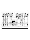
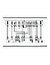
G900x/g950 installation and maintenance manual – g900x/g950 installation overview page 1-3 190-00719-00 revision d 1.2.2 system architecture the following diagrams illustrate the redundant communication paths that are in place in a typical g900x/g950 installation. Refer to appendix f-j for actual in...
Page 12
Page 1-4 g900x/g950 installation and maintenance manual – g900x installation overview revision d 190-00719-00 figure 1-2. G900x/g950 three-display interconnect summary.
Page 13
G900x/g950 installation and maintenance manual – g900x/g950 installation overview page 1-5 190-00719-00 revision d table 1-1 illustrates the differences in the number of lru’s required for a two-display installation and a three-display installation. Refer to table 1-2 for lru part numbers. Table 1-1...
Page 14
Page 1-6 g900x/g950 installation and maintenance manual – g900x installation overview revision d 190-00719-00 1.3.2 power specifications with the exception of j605 of the gia 63w, all lrus are capable of operating at either 14 or 28 vdc. See the individual lru specific environmental qualification fo...
Page 15
G900x/g950 installation and maintenance manual – g900x/g950 installation overview page 1-7 190-00719-00 revision d 1.3.3 physical specifications all width, height, and depth measurements are taken with unit rack (if applicable) and connectors. Table 1-4. G900x/g950 lru physical specifications lru wi...
Page 16
Page 1-8 g900x/g950 installation and maintenance manual – g900x installation overview revision d 190-00719-00 1.3.4 environmental specifications refer to the applicable environmental qualification form (table 1-5) for a complete list of environmental characteristics. Table 1-5. G900x/g950 lru enviro...
Page 17
G900x/g950 installation and maintenance manual – g900x/g950 installation overview page 1-9 190-00719-00 revision d 1.3.5.1 gdu 1040 cooling requirements external cooling of the gdu 1040 is required. A fan bracket (garmin p/n 115-00973-00) is available to mount an axial fan (garmin recommended fan 01...
Page 18
Page 1-10 g900x/g950 installation and maintenance manual – g900x installation overview revision d 190-00719-00 alternatively, the following fans have been evaluated and reportedly meet the minimum specification of 20 cfm airflow. This information is provided for reference only. Garmin makes no claim...
Page 19
G900x/g950 installation and maintenance manual – g900x/g950 installation overview page 1-11 190-00719-00 revision d 1.3.5.2 gia 63w and gtx 33 cooling requirements external cooling of the gia 63w and gtx 33 is required. A 5/8” diameter air fitting is provided on the rear of the mounting rack for the...
Page 20
Page 1-12 g900x/g950 installation and maintenance manual – g900x installation overview revision d 190-00719-00 1.3.5.3 thermal cooling validation garmin requires that all new g950 installations in type certificated aircraft perform thermal validation in accordance with the below plans as part of the...
Page 21
G900x/g950 installation and maintenance manual – g900x/g950 installation overview page 1-13 190-00719-00 revision d 1.4 mechanical aspects 1.4.1 g900x/g950 rack system the g900x/g950 mounting system is designed to simplify the installation, removal, and servicing of g900x/g950 lrus. The system typic...
Page 22
Page 1-14 g900x/g950 installation and maintenance manual – g900x installation overview revision d 190-00719-00 1.4.2.1 recommended lru clearance refer to table 1-9 and figure 1-6 for recommendations on garmin lru clearance and wire bend radius specifications. Garmin recommends that adequate space be...
Page 23
G900x/g950 installation and maintenance manual – g900x/g950 installation overview page 1-15 190-00719-00 revision d 1.4.3 main system rack the main system rack can be mounted directly behind the instrument panel (behind the gdu 1040 displays), or at a remote location. Two racks are available under t...
Page 24
Page 1-16 g900x/g950 installation and maintenance manual – g900x installation overview revision d 190-00719-00 the rack can be attached to the aircraft panel using nutplates as shown in figure 1-8 and appendix e or riveted using an426 flush rivets. Table 1-12. Nutplates item description garmin part ...
Page 25
G900x/g950 installation and maintenance manual – g900x/g950 installation overview page 1-17 190-00719-00 revision d 1.4.6 lru racks each lru uses a specially designed rack (except the gdu 1040). Lrus can be easily removed and replaced without the use of specialized tools (a #2 phillips screwdriver i...
Page 26
Page 1-18 g900x/g950 installation and maintenance manual – g900x installation overview revision d 190-00719-00 1.4.7 rear connector plates cast rear plates serve as connection junctions to the gtx 33, gia 63w, gea 71, and gma 1347. Rear plate part numbers are available in individual lru sections of ...
Page 27
G900x/g950 installation and maintenance manual – g900x/g950 installation overview page 1-19 190-00719-00 revision d 1.4.8 nutplate fasteners most lru racks are attached to the main system rack or remote location using nutplate fasteners as shown in table 1-13, figure 1-11, and figure 1-12. Refer ind...
Page 28
Page 1-20 g900x/g950 installation and maintenance manual – g900x installation overview revision d 190-00719-00 figure 1-12. Example of three position nutplates.
Page 29
G900x/g950 installation and maintenance manual – g900x/g950 installation overview page 1-21 190-00719-00 revision d 1.4.9 lru handles a handle-lock mechanism is used to guide and lock lrus into place. The handle has a locking stud that engages a dogleg-shaped track on the lru rack. After engaging th...
Page 30
Page 1-22 g900x/g950 installation and maintenance manual – g900x installation overview revision d 190-00719-00 1.4.10 keyplates b a figure 1-14. Keyplate/lru relationship some g900x/g950 lru racks employ a keyplate/hex-dowel system that mates with the back of certain units and their rear plates. Thi...
Page 31
G900x/g950 installation and maintenance manual – g900x/g950 installation overview page 1-23 190-00719-00 revision d 1.4.11 chips system (optional) the optional chips system provides a means of securing the display harness when the display is mounted in front of the main system rack. The flexible con...
Page 32
Page 1-24 g900x/g950 installation and maintenance manual – g900x installation overview revision d 190-00719-00 1.5 electrical considerations 1.5.1 power architecture garmin recommends that all garmin g900x/g950 installations utilize two power busses with redundant power generation sources. Those lru...
Page 33
G900x/g950 installation and maintenance manual – g900x/g950 installation overview page 1-25 190-00719-00 revision d 1.5.3 wiring harness installation allow adequate space for installation of cables and connectors. The installer shall supply and fabricate all of the cables. All electrical connections...
Page 34
Page 1-26 g900x/g950 installation and maintenance manual – g900x installation overview revision d 190-00719-00 1.5.4 cable installation 1. Route the coaxial cable to the rack location. Secure the cable in accordance with good aviation practice. 2. Trim the coaxial cable to the desired length and ins...
Page 35
G900x/g950 installation and maintenance manual – g900x/g950 installation overview page 1-27 190-00719-00 revision d 1.5.6 electrical noise because the audio panel is a point in the aircraft where signals from many pieces of equipment are brought together, take care to minimize effects from coupled i...
Page 36
Page 1-28 g900x/g950 installation and maintenance manual – g900x installation overview revision d 190-00719-00 1.6 antenna considerations 1.6.1 antenna installation follow the manufacturers’ instructions. Avoid running other wires and coaxial cables near the vor/loc antenna cable. Caution do not use...
Page 37
G900x/g950 installation and maintenance manual – g900x/g950 installation overview page 1-29 190-00719-00 revision d 1.6.7 transponder antenna location the antenna installation should be installed in accordance with ac 43.12-2a chapter 3. Note that penetration of the pressure vessel on the pressurize...
Page 38
Page 1-30 g900x/g950 installation and maintenance manual – g900x installation overview revision d 190-00719-00 table 1-17. Transponder antenna cable specifications (for reference only) max. Length (feet – [m]) insertion loss (db/100ft) ecs type mil-c-17 type rg type 6' 1.3" [1.86m] 18.0 m17/128-rg40...
Page 39
G900x/g950 installation and maintenance manual – g900x/g950 installation overview page 1-31 190-00719-00 revision d 1.6.9 vhf com/gps interference on some installation vhf com transceivers, emergency locator transmitter (elt) antennas, and direction finder (df) receiver antennas can re-radiate throu...
Page 40
Page 1-32 g900x/g950 installation and maintenance manual – g900x installation overview revision d 190-00719-00 1.8 standby instruments garmin recommends that all aircraft include the following list of standby instruments. Note these instruments are required for all g950 installations. 1.8.1 pneumati...
Page 41
G900x/g950 installation and maintenance manual – gdu 1040 page 2-1 190-00719-00 revision d 2 gdu 1040 2.1 equipment description the gdu 1040 provides a central display and user interface for the g900x/g950 integrated cockpit system. The display is mounted flush to the aircraft instrument panel using...
Page 42
Page 2-2 g900x/g950 installation and maintenance manual – gdu 1040 revision d 190-00719-00 2.1.3 system interface functions • interfacing with the gia 63w integrated avionics unit (iau) and other gdu 1040 • control and display of dual communications transceivers operating in the 118.00 to 136.975 mh...
Page 43
G900x/g950 installation and maintenance manual – gdu 1040 page 2-3 190-00719-00 revision d 2.3 environmental characteristics the table below contains general specifications. For detailed environmental specifications, see the environmental qualification form. Table 2-2. Gdu 1040 environmental charact...
Page 44
Page 2-4 g900x/g950 installation and maintenance manual – gdu 1040 revision d 190-00719-00 2.4 tso/etso table 2-3 contains a list of applicable tso/etsos for the gdu 1040. Table 2-3. Gdu 1040 tso/etso function tso/etso/sae/ rtca/eurocae category applicable lru software part numbers applicable custom...
Page 45
G900x/g950 installation and maintenance manual – gdu 1040 page 2-5 190-00719-00 revision d tso compliance, continued function tso/etso/sae/ rtca/eurocae category applicable lru software part numbers applicable custom logic device part numbers vhf radio communications receiving equipment operating wi...
Page 46
Page 2-6 g900x/g950 installation and maintenance manual – gdu 1040 revision d 190-00719-00 function tso/etso/sae/ rtca/eurocae category applicable lru software part numbers applicable custom logic device part numbers distance measuring equipment operating within the rf range of 960-1215 mhz (dme) ts...
Page 47
G900x/g950 installation and maintenance manual – gdu 1040 page 2-7 190-00719-00 revision d 2.4.1 tso/etso deviations table 2-4. Gdu 1040 tso/etso deviations tso/etso deviation 1. Garmin was granted a deviation from tso-c2d to use rtca do-178b instead of rtca do- 178a to demonstrate compliance for th...
Page 48
Page 2-8 g900x/g950 installation and maintenance manual – gdu 1040 revision d 190-00719-00 tso/etso deviations, continued tso/etso deviation 1. Garmin was granted a deviation from tso-c6d to use rtca do-160d instead of rtca do- 160b as the standard for environmental conditions and test procedures fo...
Page 49
G900x/g950 installation and maintenance manual – gdu 1040 page 2-9 190-00719-00 revision d tso/etso deviations, continued tso/etso deviation 1. Garmin was granted a deviation from tso-c10b to use sae as 8009a instead of sae as 392c as the minimum performance standard. 2. Garmin was granted a deviati...
Page 50
Page 2-10 g900x/g950 installation and maintenance manual – gdu 1040 revision d 190-00719-00 tso/etso deviations, continued tso/etso deviation 1. Garmin was granted a deviation from tso36e to use rtca do-160d instead of rtca do-160b as the standard for environmental conditions and test procedures for...
Page 51
G900x/g950 installation and maintenance manual – gdu 1040 page 2-11 190-00719-00 revision d tso/etso deviations, continued tso/etso deviation 1. Garmin was granted a deviation from tso-c41d to use rtca do-178b instead of rtca do- 178 to demonstrate compliance for the verification and validation of t...
Page 52
Page 2-12 g900x/g950 installation and maintenance manual – gdu 1040 revision d 190-00719-00 tso/etso deviations, continued tso/etso deviation 1. Garmin was granted a deviation from tso-c47 to use sae as 408c instead of sae as 408a for minimum performance standards and environmental standards. 2. Gar...
Page 53
G900x/g950 installation and maintenance manual – gdu 1040 page 2-13 190-00719-00 revision d tso/etso deviations, continued tso/etso deviation 1. Garmin was granted a deviation from tso-63c to use rtca do-160d instead of rtca do- 160a as the standard environmental conditions and test procedures for a...
Page 54
Page 2-14 g900x/g950 installation and maintenance manual – gdu 1040 revision d 190-00719-00 tso/etso deviations, continued tso/etso deviation 1. Garmin was granted a deviation from tso-c129a to use do-160d instead of do-160c for the environmental standard. 2. Garmin was granted a deviation from tso-...
Page 55
G900x/g950 installation and maintenance manual – gdu 1040 page 2-15 190-00719-00 revision d tso/etso deviations, continued tso/etso deviation 1. Garmin was granted a deviation from etso-c146 to use rtca/do-229c instead of rtca/do- 229b. 2. Garmin was granted a deviation from etso-c146 to modify the ...
Page 56
Page 2-16 g900x/g950 installation and maintenance manual – gdu 1040 revision d 190-00719-00 2.5 installation requirements 2.5.1 required accessories each of the following accessories is provided separately from the gdu 1040 unit and is required to install the unit. Table 2-5. Gdu 1040 required acces...
Page 57
G900x/g950 installation and maintenance manual – gdu 1040 page 2-17 190-00719-00 revision d 2.7 mounting requirements the gdu 1040 mounting hardware is designed to accommodate various sheet metal panel thickness (see the table 2-7). Table 2-7. Gdu mounting hardware gdu 104x mounting hardware p/n she...
Page 58
Page 2-18 g900x/g950 installation and maintenance manual – gdu 1040 revision d 190-00719-00 2.8 unit installation the gdu 1040 is installed by holding the unit flush with the instrument panel. The locking studs should be oriented with the alignment marks in the vertical position for installation. A ...
Page 59
G900x/g950 installation and maintenance manual – gma 1347 page 3-1 190-00719-00 revision d 3 gma 1347 3.1 equipment description the garmin gma 1347 is a vertically oriented panel mounted audio control and marker beacon system. The system delivers reliability and versatility for all audio controlling...
Page 60
Page 3-2 g900x/g950 installation and maintenance manual – gma 1347 revision d 190-00719-00 3.1.1 features summary • logical front panel layout • led annunciators indicate selected function • six position intercom: pilot, copilot, four passengers • three stereo headset amplifiers: one for pilot, one ...
Page 61
G900x/g950 installation and maintenance manual – gma 1347 page 3-3 190-00719-00 revision d 3.2 electrical specifications table 3-1. Gma 1347 electrical specifications characteristics specifications power requirements 14/28 vdc see the environmental qualification form for details on surge ratings and...
Page 62
Page 3-4 g900x/g950 installation and maintenance manual – gma 1347 revision d 190-00719-00 3.3 environmental specifications table 3-2. Gma 1347 environmental specifications characteristics specifications regulatory compliance rtca/do-160d environmental conditions and eurocae/ed-14d unit software rtc...
Page 63
G900x/g950 installation and maintenance manual – gma 1347 page 3-5 190-00719-00 revision d 3.4.1 tso/etso deviations table 3-4. Gma 1347 tso/etso deviations tso deviation garmin was granted a deviation from tso-c35d to use rtca do-160d instead of rtca do-138. Tso-c35d garmin was granted a deviation ...
Page 64
Page 3-6 g900x/g950 installation and maintenance manual – gma 1347 revision d 190-00719-00 3.5.2 additional equipment required • antenna sealant (use manufacturer’s instructions, install according to faa ac 43.13-2a). • cables: the installer will fabricate and supply all system cables. • hardware: #...
Page 65
G900x/g950 installation and maintenance manual – gma 1347 page 3-7 190-00719-00 revision d 3.7 mounting requirements the gma 1347 mounting surface must be capable of providing structural support and electrical bond to the aircraft to minimize radiated emi and provide protection from high-intensity r...
Page 66
Page 3-8 g900x/g950 installation and maintenance manual – gma 1347 revision d 190-00719-00 3.8 unit installation caution do not use excessive force when inserting the gma 1347 into the rack. This may damage the connectors, unit, and/or unit rack. If heavy resistance is felt during installation, stop...
Page 67
G900x/g950 installation and maintenance manual – gia 63w page 4-1 190-00719-00 revision d 4 gia 63w 4.1 equipment description the gia 63w is a microprocessor-based input/output line replaceable unit (lru) used in the g900x/g950 integrated flight deck. The gia 63w communicates with the gdu 1040 via e...
Page 68
Page 4-2 g900x/g950 installation and maintenance manual – gia 63w revision d 190-00719-00 4.1.1 interface summary 4.1.2 primary interfaces the gia 63w is designed as an open architecture system that provides the following interfaces: • 1 dedicated ethernet high-speed data bus (hsdb) input/output cha...
Page 69
G900x/g950 installation and maintenance manual – gia 63w page 4-3 190-00719-00 revision d 4.2 electrical specifications 4.2.1 waas gps specifications table 4-1. Gia 63w gps specifications characteristics specifications acquisition time a) search-the-sky (without almanac, without initial position or ...
Page 70
Page 4-4 g900x/g950 installation and maintenance manual – gia 63w revision d 190-00719-00 4.2.2 com transceiver specifications table 4-2. Gia 63w com transceiver specifications characteristics specifications audio output 100 mw minimum into a 500 Ω load. Audio response less than 6 db of variation be...
Page 71
G900x/g950 installation and maintenance manual – gia 63w page 4-5 190-00719-00 revision d 4.2.3 vor specifications table 4-3. Gia 63w vor specifications characteristics specifications receiver audio sensitivity at -103.5 dbm (s+n)/n shall not be less than 6 db. Course deviation sensitivity at –103.5...
Page 72
Page 4-6 g900x/g950 installation and maintenance manual – gia 63w revision d 190-00719-00 4.2.4 loc specifications table 4-4. Gia 63w loc specifications characteristics specifications receiver audio sensitivity at -103.5 dbm (s+n)/n shall not be less than 6 db. Course deviation sensitivity at –103.5...
Page 73
G900x/g950 installation and maintenance manual – gia 63w page 4-7 190-00719-00 revision d 4.2.5 glideslope specifications table 4-5. Gia 63w glideslope specifications characteristics specifications sensitivity at –93 dbm, deviation output shall not be less than 60% of standard deflection when glides...
Page 74
Page 4-8 g900x/g950 installation and maintenance manual – gia 63w revision d 190-00719-00 4.3 environmental specifications table 4-7. Gia 63w environmental specifications characteristics specifications operating temperature range -40°c to +65°c. For more details see environmental qualification form....
Page 75
G900x/g950 installation and maintenance manual – gia 63w page 4-9 190-00719-00 revision d 4.4.1 gia 63w tso/etso compliance table 4-8. Gia 63w tso/etso function tso/etso category applicable lru software part numbers applicable custom logic device part numbers all 006-c0084-() except 006-c0084-00 006...
Page 76
Page 4-10 g900x/g950 installation and maintenance manual – gia 63w revision d 190-00719-00 gia 63w tso/etso compliance, continued function tso/etso category applicable lru software part numbers applicable custom logic device part numbers all 006-c0084-() except 006-c0084-00 006-c0072-() 006-c0085-()...
Page 77
G900x/g950 installation and maintenance manual – gia 63w page 4-11 190-00719-00 revision d gia 63w tso/etso compliance, continued function tso/etso category applicable lru software part numbers applicable custom logic device part numbers all 006-c0084-() except 006-c0084-00 006-c0072-() 006-c0085-()...
Page 78
Page 4-12 g900x/g950 installation and maintenance manual – gia 63w revision d 190-00719-00 4.4.2 gia 63w tso/etso deviations table 4-9. Gia 63w tso/etso deviations tso/etso deviation 1. Garmin was granted a deviation from tso-c9c to use sae as 402b instead of as- 402a. 2. Garmin was granted a deviat...
Page 79
G900x/g950 installation and maintenance manual – gia 63w page 4-13 190-00719-00 revision d tso/etso deviations, continued tso/etso deviation 1. Garmin was granted a deviation from etso-2c38e to use do-160e instead of do- 160d. Etso-2c38e 2. Garmin was granted a deviation from etso-2c38e to use ed-23...
Page 80
Page 4-14 g900x/g950 installation and maintenance manual – gia 63w revision d 190-00719-00 tso/etso deviations, continued tso/etso deviation 1. Garmin was granted a deviation from etso-c145 to use do-160e instead of do-160d 2. Garmin was granted a deviation from etso-c145 to use do-229c instead of d...
Page 81
G900x/g950 installation and maintenance manual – gia 63w page 4-15 190-00719-00 revision d 4.5 installation requirements 4.5.1 required accessories each of the following accessories is provided separately from the gia 63(w) and is required to install the unit. Table 4-10. Gia 63w required accessorie...
Page 82
Page 4-16 g900x/g950 installation and maintenance manual – gia 63w revision d 190-00719-00 4.5.2.1 waas gps antennas the following is a list of waas gps antennas, currently supported by the g900x/g950: table 4-11. Gia 63w recommended waas antennas model mount style conn type satcom compatible [2] mf...
Page 83
G900x/g950 installation and maintenance manual – gia 63w page 4-17 190-00719-00 revision d 4.6 installation considerations the gia 63w interfaces with the g900x/g950 system and with various avionics equipment. Fabrication of a wiring harness is required. Sound mechanical and electrical methods and p...
Page 84
Page 4-18 g900x/g950 installation and maintenance manual – gia 63w revision d 190-00719-00 2. Electrical characteristics lna supply voltage 4.5 - 5.5 vdc lna supply current 25 lna operating frequency 1575.42 ± 10.00 mhz lna gain 26.5 db minimum lna noise figure 4.0 db maximum lna bandwidth (-3 db) 2...
Page 85
G900x/g950 installation and maintenance manual – gia 63w page 4-19 190-00719-00 revision d 4.7 mounting requirements the gia 63w is to be mounted using the g900x/g950 rack system. The unit may also be mounted remotely if desired. The kit builder must fabricate any additional mounting equipment neede...
Page 86
Page 4-20 g900x/g950 installation and maintenance manual – gia 63w revision d 190-00719-00 4.8 unit installation for final installation and assembly, refer to the outline and installation drawings shown in appendix e of this manual. 1. Assemble the backshell connectors. 2. Connect backshell connecto...
Page 87
G900x/g950 installation and maintenance manual – gia 63w page 4-21 190-00719-00 revision d 4.8.1 license requirements the telecommunications act of 1996, effective february 8, 1996, provides the fcc discretion to eliminate radio station license requirements for aircraft and ships. The gia 63w instal...
Page 88
Page 4-22 g900x/g950 installation and maintenance manual – gia 63w revision d 190-00719-00 this page intentionally left blank.
Page 89
G900x/g950 installation and maintenance manual – gea 71 page 5-1 190-00719-00 revision d 5 gea 71 5.1 equipment description the gea 71 is a micro-processor based input/output line replaceable unit (lru) used to monitor sensor inputs and drive annunciator outputs for aircraft airframe and engine syst...
Page 90
G900x/g950 installation and maintenance manual – gea 71 revision d 190-00719-00 page 5-2 5.2 electrical specifications table 5-1. Gea 71 electrical specifications characteristic specification input voltage 14/28 vdc see the environmental qualification form for details on surge ratings and minimum/ma...
Page 91
G900x/g950 installation and maintenance manual – gea 71 page 5-3 190-00719-00 revision d 5.4 tso/etso table 5-3 contains a list of applicable tso/etsos for the gea 71. Table 5-3. Gea 71 tso/etso function tso/etso category applicable lru sw part numbers fuel flow meters tso-c44b etso-c44b type i 006-...
Page 92
G900x/g950 installation and maintenance manual – gea 71 revision d 190-00719-00 page 5-4 5.4.1 tso/etso deviations table 5-4 contains a list of tso/etso deviations granted to garmin for the gea 71: table 5-4. Gea 71 tso/etso tso/etso deviation 1. Garmin was granted a deviation from tso-c43c to use s...
Page 93
G900x/g950 installation and maintenance manual – gea 71 page 5-5 190-00719-00 revision d tso/etso deviation 1. Garmin was granted a deviation from tso-c55 to use sae as 405c in place of sae as 405b to demonstrate compliance for fuel and oil quantity instruments for reciprocating engine aircraft. Tso...
Page 94
G900x/g950 installation and maintenance manual – gea 71 revision d 190-00719-00 page 5-6 5.6.1 g900x/g950 supported engines the following is a list of engines, currently supported by the g900x/g950 software: piston • continental tsio-550-e • continental io-550-n • continental io-360-es • lycoming io...
Page 95
G900x/g950 installation and maintenance manual – gea 71 page 5-7 190-00719-00 revision d 5.6.2 g900x/g950 supported piston engine sensors table 5-6 contains a list of g900x/g950 supported sensors. Caution table 5-6 contains the sensor manufacturers and part numbers that have specifically been tested...
Page 96
G900x/g950 installation and maintenance manual – gea 71 revision d 190-00719-00 page 5-8 g900x/g950 supported sensors, continued sensor suggested manufacturer sensor p/n sensor type required sensor properties gea 71 connection fuel pressure (carb) uma t1eu35g-cs (tso), or n1eu35g-cs (non-tso) pressu...
Page 97
G900x/g950 installation and maintenance manual – gea 71 page 5-9 190-00719-00 revision d table 5-7. Sensor quantity by engine type (piston only) carbureted engines fuel injected engines turbocharged engines measurement 4 cylinder 6 cylinder 4 cylinder 6 cylinder 6 cylinder egt 4 6 4 6 6 cht 4 6 4 6 ...
Page 98
G900x/g950 installation and maintenance manual – gea 71 revision d 190-00719-00 page 5-10 note the following sections contain general guidance on engine and airframe sensor installation. This information is provided for reference only. The installer should always follow any installation guidance and...
Page 99
G900x/g950 installation and maintenance manual – gea 71 page 5-11 190-00719-00 revision d figure 5-1. Egt package figure 5-2. Exhaust pipe drilled.
Page 100
G900x/g950 installation and maintenance manual – gea 71 revision d 190-00719-00 page 5-12 figure 5-3. Installed egt probe orientation.
Page 101
G900x/g950 installation and maintenance manual – gea 71 page 5-13 190-00719-00 revision d 5.6.2.2 cht (cylinder head temperature) sensor sensor description: type k grounded thermocouple installed in cht well. Two probe options exist: 1. Two piece bayonet probe with separate probe well adapter (alcor...
Page 102
G900x/g950 installation and maintenance manual – gea 71 revision d 190-00719-00 page 5-14 figure 5-5. Cht probe well figure 5-6. One piece cht probe installed.
Page 103
G900x/g950 installation and maintenance manual – gea 71 page 5-15 190-00719-00 revision d 5.6.2.3 tit (turbine inlet temperature) sensor sensor description: type k grounded thermocouple probe with screw-in type adapter. General installation guidance: to maintain g900x/g950 engine indicating system (...
Page 104
G900x/g950 installation and maintenance manual – gea 71 revision d 190-00719-00 page 5-16 5.6.2.5 rpm (revolutions per minute) sensor sensor description: 1a3c-2: standard mechanical tach drive sender (0-5 volt square wave, 2 pulses per crankshaft rev) n/t1a9-x-c: magnetic pickup tach sender (install...
Page 105
G900x/g950 installation and maintenance manual – gea 71 page 5-17 190-00719-00 revision d n/t1a9-x: the magnetic pickup tach sender is installed in the magneto bleed port. It is recommended that it be installed in the non-impulse magneto, but it can be installed in the impulse magneto if only one ma...
Page 106
G900x/g950 installation and maintenance manual – gea 71 revision d 190-00719-00 page 5-18 5.6.2.6 ammeter sensor (battery, alternator, and auxiliary) general installation guidance: current sensing on the g900x/g950 is done via the use of a traditional ammeter shunt (figure 5-14). The ammeter shunt h...
Page 107
G900x/g950 installation and maintenance manual – gea 71 page 5-19 190-00719-00 revision d figure 5-15. Ammeter shunt installed next to airframe ground 5.6.2.6.2 alternator ammeter sensor sensor description: 1c4: 100 amp / 50 mv shunt general installation guidance: given most alternators are case gro...
Page 108
G900x/g950 installation and maintenance manual – gea 71 revision d 190-00719-00 page 5-20 refer to the supplied servo or sensor installation manual and g900x/g950 interconnects in appendix f-j for proper wiring connections. Section 15 provides calibration instructions. 5.6.2.8 pressure sensor (fuel,...
Page 109
G900x/g950 installation and maintenance manual – gea 71 page 5-21 190-00719-00 revision d 5.6.2.8.1 fuel pressure sensor sensor description: t/n1eu35g-cs: 0 – 35 psig pressure transducer for carbureted engines (tso c47 on “t” model) t/n1eu70g-cs: 0 – 70 psig pressure transducer for fuel injected eng...
Page 110
G900x/g950 installation and maintenance manual – gea 71 revision d 190-00719-00 page 5-22 5.6.2.9 fuel flow sensor sensor description: floscan 201b-6 turbine fuel flow sensor. The sensor produces a current pulse signal from an opto- electronic pickup with a preamplifier. General installation guidanc...
Page 111
G900x/g950 installation and maintenance manual – gea 71 page 5-23 190-00719-00 revision d 5.6.2.10 oil temperature sensor sensor description: threaded 5/8-18 platinum resistance temperature detector (rtd) probe general installation guidance: refer to the applicable engine manual for proper location ...
Page 112
G900x/g950 installation and maintenance manual – gea 71 revision d 190-00719-00 page 5-24 5.6.3 g900x/g950 supported turboprop engine sensors table 5-8 contains a list of g900x/g950 supported sensors. Caution table 5-8 contains the sensor manufacturers and part numbers that have specifically been te...
Page 113
G900x/g950 installation and maintenance manual – gea 71 page 5-25 190-00719-00 revision d g900x/g950 supported sensors (turboprop only), continued sensor quantity suggested manufacturer sensor p/n sensor type required sensor properties gea 71 connection propeller speed (np) 1 globe 22a703 tach gener...
Page 114
G900x/g950 installation and maintenance manual – gea 71 revision d 190-00719-00 page 5-26 g900x/g950 supported sensors (turboprop only), continued sensor quantity suggested manufacturer sensor p/n sensor type required sensor properties gea 71 connection itt 1 pratt & whitney engine specific k thermo...
Page 115
G900x/g950 installation and maintenance manual – gea 71 page 5-27 190-00719-00 revision d note the following sections contain general guidance on engine and airframe sensor installation. This information is provided for reference only. The installer should always follow any installation guidance and...
Page 116
G900x/g950 installation and maintenance manual – gea 71 revision d 190-00719-00 page 5-28 5.6.3.3.1 fuel pressure transducer sensor description: apte-6-1000-100g is a 0-100 psig pressure transducer. 5.6.3.3.2 oil pressure transducer sensor description: apte-6-1000-200g is a 0-200 psig pressure trans...
Page 117
G900x/g950 installation and maintenance manual – gea 71 page 5-29 190-00719-00 revision d 5.6.3.6 fuel flow sensor description: electronics international ft-180 (black cube) turbine flow transducer. General installation guidance: refer to the electronics international ft-180 flow transducer (black c...
Page 118
G900x/g950 installation and maintenance manual – gea 71 revision d 190-00719-00 page 5-30 5.7 mounting requirements the gea 71 mounting surface should be capable of providing a sufficient electrical bond to the aircraft to minimize radiated emi and provide protection from high-intensity radiation fi...
Page 119
G900x/g950 installation and maintenance manual – gea 71 page 5-31 190-00719-00 revision d 5.7.1 thermocouple installation the backshell assembly also houses a thermocouple reference junction (needed only if the gea 71 is to monitor temperatures using thermocouple sensors). The thermocouple kit is av...
Page 120
G900x/g950 installation and maintenance manual – gea 71 revision d 190-00719-00 page 5-32 5.8 unit installation for final installation and assembly, refer to the outline and installation drawings shown in appendix e of this manual. 1. Assemble the connector backshells. 2. Connect both connectors to ...
Page 121
G900x/g950 installation and maintenance manual – gdc 74a page 6-1 190-00719-00 revision d 6 gdc 74a 6.1 equipment description the garmin gdc 74a air data computer is a remote mounted device that provides air data for flight instrumentation. The system measures aircraft static and impact pressure inf...
Page 122
Page 6-2 g900x/g950 installation and maintenance manual – gdc 74a revision d 190-00719-00 6.1.1 interface summary the gdc 74a provides the following interface connections via the rear connector. • arinc 429 output to grs 77 ahrs • 2 arinc 429 outputs to gdu 104x pfd/mfd and gia 63w integrated avioni...
Page 123
G900x/g950 installation and maintenance manual – gdc 74a page 6-3 190-00719-00 revision d 6.3 environmental specifications note the gdc 74a may require a warm-up period of 15 minutes to reach full accuracy (30 minutes if the environmental temperature is less than 0°c). Table 6-2 contains a list of e...
Page 124
Page 6-4 g900x/g950 installation and maintenance manual – gdc 74a revision d 190-00719-00 6.4 tso/etso table 6-3 contains a list of applicable tso/etsos for the gdc 74a. Table 6-3. Gdc 74a tso/etso function tso/etso applicable lru software part numbers applicable cld part numbers air data computer t...
Page 125
G900x/g950 installation and maintenance manual – gdc 74a page 6-5 190-00719-00 revision d 6.4.2 tso/etso deviations for the gtp 59 the following deviations have been requested and granted for the gtp 59: table 6-6. Gtp 59 tso/etso deviations tso/etso deviation 1. Garmin was granted a deviation from ...
Page 126
Page 6-6 g900x/g950 installation and maintenance manual – gdc 74a revision d 190-00719-00 table 6-8 contains a list of items found in the gtp 59 outside air temperature (oat) probe kit (011- 00978-00). The gtp 59 probe has an attached pigtail. Table 6-8. Gtp outside air temperature kit item descript...
Page 127
G900x/g950 installation and maintenance manual – gdc 74a page 6-7 190-00719-00 revision d 6.6.2 pneumatic plumbing the gdc 74a has two ports that are connected to the aircraft’s pitot pressure source and static pressure source. The two ports are labeled on the unit. Pressure ports have 1/8-27 anpt f...
Page 128
Page 6-8 g900x/g950 installation and maintenance manual – gdc 74a revision d 190-00719-00 6.6.4 pneumatic connections the installer is required to fabricate pneumatic hose connections and attach the aircraft pitot pressure source and aircraft static pressure source to the gdc 74a. Caution check pneu...
Page 129
G900x/g950 installation and maintenance manual – gdc 74a page 6-9 190-00719-00 revision d 6.7 mounting requirements the gdc 74a mounting surface must be capable of providing structural support and electrical bond to the aircraft to minimize radiated emi and provide protection from high-intensity rad...
Page 130
Page 6-10 g900x/g950 installation and maintenance manual – gdc 74a revision d 190-00719-00 6.8.1 gtp 59 oat probe installation note the following instructions are general guidance. Table 6-9 contains a list of parts needed for the gtp 59 installation and interconnect harness. Reference numbers in th...
Page 131
G900x/g950 installation and maintenance manual – gdc 74a page 6-11 190-00719-00 revision d 5. Strip back 1/8” (0.125”) of insulation and crimp pins (11) to each of the conductors in the shielded cable. 6. Cut an awg #16 (8) wire to 3” long. Strip back 0.5” of insulation from this cable. Connect the ...
Page 132
Page 6-12 g900x/g950 installation and maintenance manual – gdc 74a revision d 190-00719-00 this page intentionally left blank.
Page 133
G900x/g950 installation and maintenance manual – grs 77 and gmu 44 page 7-1 190-00719-00 revision d 7. Grs 77 and gmu 44 7.1 equipment description the garmin grs 77 ahrs (attitude and heading reference system) and gmu 44 magnetometer are remote mounted devices that provide flight attitude and headin...
Page 134
Page 7-2 g900x/g950 installation and maintenance manual – grs 77 and gmu 44 revision d 190-00719-00 1) north of 65° north latitude between longitude 75° w and 120° w. (northern canada) 2) south of 55° south latitude between longitude 120° e and 165° e. (region south of australia and new zealand) int...
Page 135
G900x/g950 installation and maintenance manual – grs 77 and gmu 44 page 7-3 190-00719-00 revision d 7.3.1 environmental qualification form refer to the grs 77 environmental qualification form (garmin part number 005-00165-31) and the gmu 44 environmental qualification form (garmin part number 005-00...
Page 136
Page 7-4 g900x/g950 installation and maintenance manual – grs 77 and gmu 44 revision d 190-00719-00 7.4.3 tso/etso deviations table 7-5 contains a list of applicable tso and sae deviations for the grs 77 and gmu 44. Table 7-5. Grs 77/gmu 44 tso/etso deviations tso deviation 1. Garmin was granted a d...
Page 137
G900x/g950 installation and maintenance manual – grs 77 and gmu 44 page 7-5 190-00719-00 revision d 7.5 installation requirements 7.5.1 equipment available table 7-6. Grs 77/gmu 44 accessories item garmin p/n sub assy, connector kit, grs 77 w/shield block 011-00869-01 installation rack, grs 77 115-0...
Page 138
Page 7-6 g900x/g950 installation and maintenance manual – grs 77 and gmu 44 revision d 190-00719-00 7.7.1 grs 77 ahrs mounting guidelines the grs 77 includes an extremely sensitive strap-down inertial measurement unit. It must be mounted rigidly to the aircraft primary structure. Do not use shock mo...
Page 139
G900x/g950 installation and maintenance manual – grs 77 and gmu 44 page 7-7 190-00719-00 revision d 7.7.2 gmu 44 magnetometer mounting guidelines the gmu 44 is an extremely sensitive three-axis magnetic sensor. It is more sensitive to nearby magnetic disturbances than a flux gate magnetometer. For t...
Page 140
Page 7-8 g900x/g950 installation and maintenance manual – grs 77 and gmu 44 revision d 190-00719-00 align the gmu 44 mounting rack’s forward direction to within 0.5° in heading of the aircraft forward direction (longitudinal axis). If it is not possible to guarantee this accuracy, installation align...
Page 141
G900x/g950 installation and maintenance manual – grs 77 and gmu 44 page 7-9 190-00719-00 revision d 7.8 unit installation note when mounting the grs 77 rack to the airframe, and the unit to the rack, it is important to ensure that fastening hardware is tight for proper unit operation. Use a #2 phill...
Page 142
Page 7-10 g900x/g950 installation and maintenance manual – grs 77 and gmu 44 revision d 190-00719-00 7.8.1 grs 77 rack to unit flatness check while installing the grs 77 unit on its rack, a flatness check is required to ensure that the unit’s base is properly preloaded after installation. Place the ...
Page 143
G900x/g950 installation and maintenance manual – gtx 33 page 8-1 190-00719-00 revision d 8 gtx 33 8.1 equipment description the garmin gtx 33 rack mounted mode s transponder is a radio transmitter and receiver that operates on radar frequencies, receiving ground radar or tcas interrogations at 1030 ...
Page 144
Page 8-2 g900x/g950 installation and maintenance manual – gtx 33 revision d 190-00719-00 the gtx 33 with software version 4.01 meets mode s enhanced surveillance requirements. Mode s enhanced surveillance is used predominantly in european airspace. It provides information consisting of additional ai...
Page 145
G900x/g950 installation and maintenance manual – gtx 33 page 8-3 190-00719-00 revision d 8.1.3 interface summary the gtx 33 provides the following interface connections via the rear connector. • ten (10) encoding altimeter inputs • external ident input • external stby input (useful for dual transpon...
Page 146
Page 8-4 g900x/g950 installation and maintenance manual – gtx 33 revision d 190-00719-00 8.2 electrical specifications table 8-1. Gtx 33 electrical specifications characteristic specification transmitter frequency 1090 mhz ±1 mhz transmitter power 125 watts minimum, 250 watts nominal receiver freque...
Page 147
G900x/g950 installation and maintenance manual – gtx 33 page 8-5 190-00719-00 revision d 8.3 environmental characteristics table 8-2. Gtx 33 environmental specifications characteristic specification regulatory compliance; gtx 33 rtca do-160d, do-181c environmental conditions and eurocae/ed-73a unit ...
Page 148
Page 8-6 g900x/g950 installation and maintenance manual – gtx 33 revision d 190-00719-00 8.5 installation requirements 8.5.1 available equipment table 8-4. Gtx 33 accessories item garmin catalog part number modular install rack, gtx 33/gtx 33d 115-00438-00 nutplate kit 011-00915-01 or gtx 33/gtx 33d...
Page 149
G900x/g950 installation and maintenance manual – gtx 33 page 8-7 190-00719-00 revision d 8.5.2 additional equipment required the following installation accessories are required but not provided: • cables – the installer will supply all system cables including circuit breakers. • hardware – #6-32 x 1...
Page 150
Page 8-8 g900x/g950 installation and maintenance manual – gtx 33 revision d 190-00719-00 8.7 mounting requirements the gtx 33 mounting surface must be capable of providing structural support and electrical bond to the aircraft to minimize radiated emi and provide protection from high-intensity radia...
Page 151
G900x/g950 installation and maintenance manual – gtx 33 page 8-9 190-00719-00 revision d figure 8-1. Gtx 33 modular rack (115-00438-00) figure 8-2. Gtx 33 stand-alone rack (115-00629-00).
Page 152
Page 8-10 g900x/g950 installation and maintenance manual – gtx 33 revision d 190-00719-00 8.8 unit installation for final installation and assembly, refer to the outline and installation drawings shown in appendix e of this manual. 1. Assemble the backshell connector. 2. Connect backshell connector ...
Page 153
G900x/g950 installation and maintenance manual – gcu 476 page 9-1 190-00719-00 revision d 9 gcu 476 (optional) 9.1 equipment description the gcu 476 refers to the garmin flight management system (fms) controller used in the g900x/g950 integrated cockpit system. The gcu 476 provides alphanumeric, sof...
Page 154
Page 9-2 g900x/g950 installation and maintenance manual – gcu 476 revision d 190-00719-00 9.2 electrical specifications table 9-1. Gcu 476 electrical specifications characteristics specifications power requirements 14/28 vdc. See the environmental qualification form for details on surge ratings and ...
Page 155
G900x/g950 installation and maintenance manual – gcu 476 page 9-3 190-00719-00 revision d 9.4 tso/etso table 9-3 contains a list of applicable tso/etsos for the gcu 476. Table 9-3. Gcu 476 tso/etso function tso/etso/sae/ rtca/eurocae category applicable lru software part numbers airborne multipurpos...
Page 156
Page 9-4 g900x/g950 installation and maintenance manual – gcu 476 revision d 190-00719-00 9.7 mounting requirements the gcu 476 is to be mounted using the gcu 476 unit rack, see figure 9-1. Installer must fabricate any additional mounting equipment needed, use outline and installation drawings for r...
Page 157
G900x/g950 installation and maintenance manual – gdl 69(a) page 10-1 190-00719-00 revision d 10 gdl 69(a)/grt 10/grc 10 (optional) 10.1 equipment description the gdl 69 is a weather data receiver. The gdl 69a is an xm satellite radio data link receiver that receives both xm satellite radio and weath...
Page 158
Page 10-2 g900x/g950 installation and maintenance manual – gdl 69(a) revision d 190-00719-00 10.2 electrical specifications table 10-1. Gdl 69(a) electrical specifications characteristics specifications power requirements 14/28 vdc. See the environmental qualification form for details on surge ratin...
Page 159
G900x/g950 installation and maintenance manual – gdl 69(a) page 10-3 190-00719-00 revision d 10.3.1 environmental qualification form refer to the following documents for a complete list of environmental characteristics. • gdl 69/gdl 69a environmental qualification form, garmin part number 005-00217-...
Page 160
Page 10-4 g900x/g950 installation and maintenance manual – gdl 69(a) revision d 190-00719-00 10.5 installation requirements 10.5.1 required accessories table 10-7. Gdl 69(a) accessories item garmin p/n back plate assembly 011-00796-35 remote mount rack gdl 69 115-00658-00 connector kit assembly 011-...
Page 161
G900x/g950 installation and maintenance manual – gdl 69(a) page 10-5 190-00719-00 revision d 10.7 mounting requirements 10.7.1 remote mount rack the remote mount rack can be installed in a variety of locations, such as the electronics bay, behind the instrument panel, under the seat or behind the re...
Page 162
Page 10-6 g900x/g950 installation and maintenance manual – gdl 69(a) revision d 190-00719-00 10.9 continued airworthiness maintenance of the gdl 69(a)/grt 10/grc 10 is “on condition” only..
Page 163
G900x/g950 installation and maintenance manual – gwx 68 page 11-1 190-00719-00 revision d 11 gwx 68 (optional) 11.1 equipment description the gwx 68 airborne weather radar is a microprocessor-based line replaceable unit (lru) that outputs weather radar data to an external mfd. The gwx 68 communicate...
Page 164
Page 11-2 g900x/g950 installation and maintenance manual – gwx 68 revision d 190-00719-00 11.2 electrical specifications table 11-1. Gwx 68 electrical specifications characteristics specifications display colors 4 colors selectable ranges 2.5, 5, 10, 20, 40, 60, 80, 100, 120, 160, 240, and 320nm wea...
Page 165
G900x/g950 installation and maintenance manual – gwx 68 page 11-3 190-00719-00 revision d 11.4 tso/etso function tso/etso category applicable lru sw part numbers airborne weather and ground mapping pulsed radars tso-c63c etso-2c63c class 7 006-b0266-06 and later 006-b0266-() 11.4.1 tso/etso deviatio...
Page 166
Page 11-4 g900x/g950 installation and maintenance manual – gwx 68 revision d 190-00719-00 11.5 installation requirements 11.5.1 required accessories table 11-3. Gwx 68 accessories item garmin p/n gwx 68 installation kit 011-01114-00 11.6 installation considerations the gwx 68 is designed to be rigid...
Page 167
G900x/g950 installation and maintenance manual – gwx 68 page 11-5 190-00719-00 revision d 11.8.1 connector kit assembly the gwx 68 connector kit (011-01114-00) includes one garmin backshell assembly. Garmin’s backshell connectors give the installer the ability to quickly and easily terminate shield ...
Page 168
Page 11-6 g900x/g950 installation and maintenance manual – gwx 68 revision d 190-00719-00 figure 11 - 1. Shield block install onto backshell connector assembly table 11 - 5. Shield block components backshell assembly garmin p/n shield block/right angle adapter garmin p/n 011-00950-12 (25/44 pin high...
Page 169
G900x/g950 installation and maintenance manual – gwx 68 page 11-7 190-00719-00 revision d 1. Attach the shield block(s) (2) to the backshell (1) by inserting the flathead screws (3) through the holes on the shield block and threading into the tapped holes on the backshell (1). (see figure 11-1). The...
Page 170
Page 11-8 g900x/g950 installation and maintenance manual – gwx 68 revision d 190-00719-00 preferred method, solder sleeves: slide a solder sleeve (5) onto the prepared cable assembly (4) and connect the flat braid (6) to the shield using a heat gun approved for use with solder sleeves. It may be eas...
Page 171
G900x/g950 installation and maintenance manual – gwx 68 page 11-9 190-00719-00 revision d secondary method, heat shrink instead of solder sleeves: solder a flat braid (6) to the shield exposed through the window of the prepared cable assembly (4). Ensure a solid electrical connection through the use...
Page 172
Page 11-10 g900x/g950 installation and maintenance manual – gwx 68 revision d 190-00719-00 8. Guidelines for terminating the newly cutoff flat braid(s) (item 6) with insulated ring terminals (9): • each tapped hole on the shield block (2) may accommodate only two ring terminals (9). • it is preferre...
Page 173
G900x/g950 installation and maintenance manual – gwx 68 page 11-11 190-00719-00 revision d 9. Repeat steps 2 through 8 as needed for the remaining shielded cables. 10. Terminate the ring terminals to the shield block (2) by placing items on the pan head screw (10) in the following order: split washe...
Page 174
Page 11-12 g900x/g950 installation and maintenance manual – gwx 68 revision d 190-00719-00 this page intentionally left blank.
Page 175
G900x/g950 installation and maintenance manual – garmin gps waas antenna page 12-1 190-00719-00 revision d 12 garmin gps waas antennas 12.1 description this section provides mechanical and electrical installation requirements for installing the following garmin gps waas antennas: • ga 35 teardrop gp...
Page 176
Page 12-2 g900x/g950 installation and maintenance manual – garmin gps waas antenna revision d 190-00719-00 12.3 ga 36 arinc mount gps waas antenna 12.3.1 specifications table 12-2. Ga 36 waas specifications characteristics specifications frequency range 1575 mhz +/- 10 mhz polarization right hand ci...
Page 177
G900x/g950 installation and maintenance manual – garmin gps waas antenna page 12-3 190-00719-00 revision d 12.4 ga 37 arinc mount gps waas and xm antenna 12.4.1 specifications table 12-3. Ga 37 waas specifications characteristics specifications frequency range 1575 mhz +/- 10 mhz polarization right ...
Page 178
Page 12-4 g900x/g950 installation and maintenance manual – garmin gps waas antenna revision d 190-00719-00 12.5 gps waas and fis antenna installation considerations and mounting requirements 12.5.1 teardrop footprint antennas: ga 35 materials required: • nitrile o-ring - 26.64mm id x 2.62mm w, size ...
Page 179
G900x/g950 installation and maintenance manual – garmin gps waas antenna page 12-5 190-00719-00 revision d 12.5.3 antenna mounting location the gps antenna is a key element in the overall system performance and integrity for a gps/waas navigation system. The mounting location, geometry, and surround...
Page 180
Page 12-6 g900x/g950 installation and maintenance manual – garmin gps waas antenna revision d 190-00719-00 the figure below shows the recommended placement of antennas..
Page 181
G900x/g950 installation and maintenance manual – garmin gps waas antenna page 12-7 190-00719-00 revision d 12.5.4 buried antennas (below the skin covering or glare shield) note garmin’s gia 63w waas gps receiver requires that supported gps antennas be mounted external to the aircraft in accordance w...
Page 182
Page 12-8 g900x/g950 installation and maintenance manual – garmin gps waas antenna revision d 190-00719-00 figure 12-3. Carbon / glass buried antenna area.
Page 183
G900x/g950 installation and maintenance manual – garmin gps waas antenna page 12-9 190-00719-00 revision d mounting the antenna under the glare shield is a good option for xm – fis antennas, it typically is not the best option for your waas gps antenna. This location results in the aft fuselage shad...
Page 184
Page 12-10 g900x/g950 installation and maintenance manual – garmin gps waas antenna revision d 190-00719-00 12.5.7 antenna grounding the antenna is grounded through the mounting hardware and the coax connection. The mounting hardware (washers and nuts) and doubler plate should make contact with an u...
Page 185
G900x/g950 installation and maintenance manual – garmin gps waas antenna page 12-11 190-00719-00 revision d 12.5.9 preparation of doubler a. Use garmin p/n: 115-00846-10, or refer to table 12-5 for guidance on selecting the appropriate doubler drawing based on the thickness of skin at the antenna lo...
Page 186
Page 12-12 g900x/g950 installation and maintenance manual – garmin gps waas antenna revision d 190-00719-00 12.5.11 reference figures figure 12-5. Doubler design, teardrop footprint antenna, skin thickness 0.032" to 0.049" figure 12-6. Doubler design, teardrop footprint antenna, skin thickness 0.049...
Page 187
G900x/g950 installation and maintenance manual – garmin gps waas antenna page 12-13 190-00719-00 revision d figure 12-7. Doubler design, teardrop footprint antenna, skin thickness 0.051" to 0.063" figure 12-8. Sample doubler location, teardrop footprint antenna, metal skin aircraft.
Page 188
Page 12-14 g900x/g950 installation and maintenance manual – garmin gps waas antenna revision d 190-00719-00 figure 12-9. Skin cutout detail, teardrop footprint antenna, skin thickness 0.032" to 0.049" figure 12-10. Skin cutout detail, teardrop footprint antenna, skin thickness 0.049" to 0.051".
Page 189
G900x/g950 installation and maintenance manual – garmin gps waas antenna page 12-15 190-00719-00 revision d figure 12-11. Skin cutout detail, teardrop footprint antenna, skin thickness 0.051" to 0.063" figure 12-12. Doubler installation, teardrop footprint antenna, skin thickness 0.032" to 0.049".
Page 190
Page 12-16 g900x/g950 installation and maintenance manual – garmin gps waas antenna revision d 190-00719-00 figure 12-13. Doubler installation, teardrop footprint antenna, skin thickness 0.049" to 0.051" figure 12-14. Doubler installation, teardrop footprint antenna, skin thickness 0.051" to 0.063".
Page 191
G900x/g950 installation and maintenance manual – garmin gps waas antenna page 12-17 190-00719-00 revision d figure 12-15. Through mount teardrop footprint antenna installation.
Page 192
Page 12-18 g900x/g950 installation and maintenance manual – garmin gps waas antenna revision d 190-00719-00 12.6 arinc 743 footprint antenna installation (ga 36 and ga 37) this section describes the structural mounting of the arinc 743 footprint antenna installation. One acceptable method is to use ...
Page 193
G900x/g950 installation and maintenance manual – garmin gps waas antenna page 12-19 190-00719-00 revision d 12.6.1 preparation of doubler a. Use garmin p/n: 115-00846-00, or refer to table 12-6 for guidance on selecting the appropriate doubler drawing based on the thickness of skin at the antenna lo...
Page 194
Page 12-20 g900x/g950 installation and maintenance manual – garmin gps waas antenna revision d 190-00719-00 12.6.3 reference figures figure 12-16. Doubler design, arinc 743 footprint antenna, skin thickness 0.032" to 0.049".
Page 195
G900x/g950 installation and maintenance manual – garmin gps waas antenna page 12-21 190-00719-00 revision d figure 12-17. Doubler design, arinc 743 footprint antenna, skin thickness 0.049" to 0.051".
Page 196
Page 12-22 g900x/g950 installation and maintenance manual – garmin gps waas antenna revision d 190-00719-00 figure 12-18. Doubler design, arinc 743, skin thickness 0.051" to 0.063".
Page 197
G900x/g950 installation and maintenance manual – garmin gps waas antenna page 12-23 190-00719-00 revision d figure 12-19. Sample doubler location, arinc 743 antenna, metal skin aircraft figure 12-20. Skin cutout detail, ga 36 antenna, skin thickness 0.032" to 0.049".
Page 198
Page 12-24 g900x/g950 installation and maintenance manual – garmin gps waas antenna revision d 190-00719-00 figure 12-21. Skin cutout detail, ga 36 antenna, skin thickness 0.049" to 0.051" figure 12-22. Skin cutout detail, ga 36 antenna, skin thickness 0.051" to 0.063".
Page 199
G900x/g950 installation and maintenance manual – garmin gps waas antenna page 12-25 190-00719-00 revision d figure 12-23. Skin cutout detail, ga 37 antenna, skin thickness 0.032" to 0.049" figure 12-24. Skin cutout detail, ga 37 antenna, skin thickness 0.049" to 0.051".
Page 200
Page 12-26 g900x/g950 installation and maintenance manual – garmin gps waas antenna revision d 190-00719-00 figure 12-25. Skin cutout detail, ga 37 antenna, skin thickness 0.051" to 0.063" figure 12-26. Doubler installation, arinc 743 footprint antenna, skin thickness 0.032" to 0.049".
Page 201
G900x/g950 installation and maintenance manual – garmin gps waas antenna page 12-27 190-00719-00 revision d figure 12-27. Doubler installation, arinc 743 footprint antenna, skin thickness 0.049" to 0.051" figure 12-28. Doubler installation, arinc 743 footprint, skin thickness 0.051" to 0.063".
Page 202
Page 12-28 g900x/g950 installation and maintenance manual – garmin gps waas antenna revision d 190-00719-00 figure 12-29. Installation of arinc 743 footprint antenna.
Page 203
G900x/g950 installation and maintenance manual – garmin gps waas antenna page 12-29 190-00719-00 revision d 12.7 non-structural mount installation this section provides installation examples and considerations for non-structural mounting of teardrop and arinc 743 footprint antennas. Typical installa...
Page 204
Page 12-30 g900x/g950 installation and maintenance manual – garmin gps waas antenna revision d 190-00719-00 12.7.1 generic non-structural installation of arinc 743 footprint antenna figure 12-31 shows the generic non-structural installation for the arinc 743 footprint antenna. A doubler plate simila...
Page 205
G900x/g950 installation and maintenance manual – garmin gps waas antenna page 12-31 190-00719-00 revision d 12.7.3 non-structural installation to glareshield figure12-32 shows an example of a bracket created to support an antenna mounted on the underside of the glare shield. Figure 12-33 shows the n...
Page 206
Page 12-32 g900x/g950 installation and maintenance manual – garmin gps waas antenna revision d 190-00719-00 12.7.4 non-structural installation to airframe figure 12-34 and figure 12-35 show examples of non-structural mounting of the antenna to the airframe of a tube-and-fabric aircraft. Figure 12-36...
Page 207
G900x/g950 installation and maintenance manual – garmin gps waas antenna page 12-33 190-00719-00 revision d figure 12-35. Example arinc 743 footprint in airframe under fabric skin table 12-7 presents minimum distance requirements between the tube structure and the antenna for cases where the antenna...
Page 208
Page 12-34 g900x/g950 installation and maintenance manual – garmin gps waas antenna revision d 190-00719-00 figure 12-36. Example teardrop footprint antenna mounting under fabric skin figure 12-37 is an example of an external, non-structural mounting of the antenna in a tube-and-fabric aircraft. The...
Page 209
G900x/g950 installation and maintenance manual – non lru specific installation information page 13-1 190-00719-00 revision d 13 non lru specific installation information 13.1 shield block installation instructions 13.1.1 shield block installation parts list of parts: tables 13-1, 13-2, and 13-3 prov...
Page 210
Page 13-2 g900x/g950 installation and maintenance manual – non lru specific installation information revision d 190-00719-00 table 13-2. Gpn: 011-01169-00 – sub-assy,grnd adaptr,shell 1-3 figure ref description qty. Included gpn or mil spec not shown adapter,ring term,shell sz 1,2,3 1 117-00147-00 3...
Page 211
G900x/g950 installation and maintenance manual – non lru specific installation information page 13-3 190-00719-00 revision d figure 13-1. Shield block install onto a backshell (78 pin example) note: “ar” denotes quantity “as required” for the particular installation.
Page 212
Page 13-4 g900x/g950 installation and maintenance manual – non lru specific installation information revision d 190-00719-00 13.2.1 shield termination technique – method a.1 (standard) 1. Attach the shield block(s) (item 2) to the backshell (item 1) by inserting the flathead screws (item 3) through ...
Page 213
G900x/g950 installation and maintenance manual – non lru specific installation information page 13-5 190-00719-00 revision d table 13-5. Shielded cable preparations for garmin connectors backshell size number of pins std/hd float min (inches) float max (inches) ideal float (inches) window min (inche...
Page 214
Page 13-6 g900x/g950 installation and maintenance manual – non lru specific installation information revision d 190-00719-00 solder sleeves with pre-installed flat braid a preferred solder sleeve would be the raychem s03 series with the thermochromic temperature indicator (s03-02-r-9035-100, s03-03-...
Page 215
G900x/g950 installation and maintenance manual – non lru specific installation information page 13-7 190-00719-00 revision d preferred method: the jacket and shield should be cut off at the same point so no shield is exposed. Slide 0.75 inches minimum of teflon heat shrinkable tubing (item 7) onto t...
Page 216
Page 13-8 g900x/g950 installation and maintenance manual – non lru specific installation information revision d 190-00719-00 8. Guidelines for terminating the newly cutoff flat braid(s) (item 6) with insulated ring terminals (item 9): • each tapped hole on the shield block (item 2) may accommodate o...
Page 217
G900x/g950 installation and maintenance manual – non lru specific installation information page 13-9 190-00719-00 revision d 13.3.1 shield termination technique - method a.2 (daisy chain) in rare situations where more braids need to be terminated for a connector than three per ring terminal it is al...
Page 218
Page 13-10 g900x/g950 installation and maintenance manual – non lru specific installation information revision d 190-00719-00 13.4.1 shield termination – method b.1 (quick term) if desired, the drain wire termination (item 5) and the floating shield termination (item 7) can be effectively combined i...
Page 219
G900x/g950 installation and maintenance manual – non lru specific installation information page 13-11 190-00719-00 revision d note reference section 13.1.2 for recommended solder sleeves and flat braid. The same recommendations are applicable to this technique. Secondary method: solder a flat braid ...
Page 220
Page 13-12 g900x/g950 installation and maintenance manual – non lru specific installation information revision d 190-00719-00 13.5.1 shield termination-method b.2 (daisy chain-quick term) in rare situations where more braids need to be terminated for a connector than three per ring terminal it is al...
Page 221
G900x/g950 installation and maintenance manual – non lru specific installation information page 13-13 190-00719-00 revision d 13.6.1 daisy chain between methods a and b in rare situations where more braids need to be terminated for a connector than three per ring terminal and a mixture of methods a ...
Page 222
Page 13-14 g900x/g950 installation and maintenance manual – non lru specific installation information revision d 190-00719-00 13.7.1 double-shield termination technique - method c.1 in rare situations where double shielding may be necessary, the outer shield should be grounded at both ends, while th...
Page 223
G900x/g950 installation and maintenance manual – non lru specific installation information page 13-15 190-00719-00 revision d 13.8.1 double-shield termination technique (quick term) - method c.2 in addition to method c.1, described previously, another suitable method for double-shielding wires is pr...
Page 224
Page 13-16 g900x/g950 installation and maintenance manual – non lru specific installation information revision d 190-00719-00 13.9.1 id program pins (strapping) id program pins provide a ground reference used by the hardware as a means of configuration for system identification. The following instru...
Page 225
G900x/g950 installation and maintenance manual – non lru specific installation information page 13-17 190-00719-00 revision d 13.10.1 splicing signal wires notes c1. Figure 13-10 illustrates that a splice must be made within a 3 inch window from outside the edge of strain relief to the end of the 3 ...
Page 226
Page 13-18 g900x/g950 installation and maintenance manual – non lru specific installation information revision d 190-00719-00 this page intentionally left blank.
Page 227
G900x/g950 installation and maintenance manual – 3 rd party interfaces page 14-1 190-00719-00 revision d 14 3rd party interfaces 14.1 discretes g900x/g950 annunciations are activated based on a series of discrete triggers. Discrete switches are only needed if associated annunciations are desired. Re...
Page 228
Page 14-2 g900x/g950 installation and maintenance manual – 3 rd party interfaces revision d 190-00719-00 g900x/g950 annunciation triggers, continued trigger reference number trigger name trigger type active state (refer to table 14-2 for description) configuration category g900x input (see interconn...
Page 229
G900x/g950 installation and maintenance manual – 3 rd party interfaces page 14-3 190-00719-00 revision d g900x/g950 annunciation triggers, continued trigger reference number trigger name trigger type active state (refer to table 14-2 for description) configuration category g900x input (see interconn...
Page 230
Page 14-4 g900x/g950 installation and maintenance manual – 3 rd party interfaces revision d 190-00719-00 table 14-3. G900x/g950 annunciations descriptive text brief text annunciation type configuration category required triggers (reference table 14-1) annunciation logic (refer to tables 14-4 through...
Page 231
G900x/g950 installation and maintenance manual – 3 rd party interfaces page 14-5 190-00719-00 revision d g900x/g950 annunciations, continued descriptive text brief text annunciation type configuration category required triggers (reference table 14-1) annunciation logic (refer to tables 14-4 through ...
Page 232
Page 14-6 g900x/g950 installation and maintenance manual – 3 rd party interfaces revision d 190-00719-00 g900x/g950 annunciations, continued descriptive text brief text annunciation type configuration category required triggers (reference table 14-1) annunciation logic (refer to tables 14-4 through ...
Page 233
G900x/g950 installation and maintenance manual – 3 rd party interfaces page 14-7 190-00719-00 revision d g900x/g950 annunciations, continued descriptive text brief text annunciation type configuration category required triggers (reference table 14-1) annunciation logic (refer to tables 14-4 through ...
Page 234
Page 14-8 g900x/g950 installation and maintenance manual – 3 rd party interfaces revision d 190-00719-00 g900x/g950 annunciations, continued descriptive text brief text annunciation type configuration category required triggers (reference table 14-1) annunciation logic (refer to tables 14-4 through ...
Page 235
G900x/g950 installation and maintenance manual – 3 rd party interfaces page 14-9 190-00719-00 revision d g900x/g950 annunciations, continued descriptive text brief text annunciation type configuration category required triggers (reference table 14-1) annunciation logic (refer to tables 14-4 through ...
Page 236
Page 14-10 g900x/g950 installation and maintenance manual – 3 rd party interfaces revision d 190-00719-00 g900x/g950 annunciations, continued descriptive text brief text annunciation type configuration category required triggers (reference table 14-1) annunciation logic (refer to tables 14-4 through...
Page 237
G900x/g950 installation and maintenance manual – 3 rd party interfaces page 14-11 190-00719-00 revision d g900x/g950 annunciations, continued descriptive text brief text annunciation type configuration category required triggers (reference table 14-1) annunciation logic (refer to tables 14-4 through...
Page 238
Page 14-12 g900x/g950 installation and maintenance manual – 3 rd party interfaces revision d 190-00719-00 g900x/g950 annunciations, continued descriptive text brief text annunciation type configuration category required triggers (reference table 14-1) annunciation logic (refer to tables 14-4 through...
Page 239
G900x/g950 installation and maintenance manual – 3 rd party interfaces page 14-13 190-00719-00 revision d g900x/g950 annunciations, continued descriptive text brief text annunciation type configuration category required triggers (reference table 14-1) annunciation logic (refer to tables 14-4 through...
Page 240
Page 14-14 g900x/g950 installation and maintenance manual – 3 rd party interfaces revision d 190-00719-00 table 14-4. G900x fuel quantity color band definitions airframe red (gallons) amber (gallons) green (gallons) black (gallons) iv 0 to 1 1 to 8 8 to 45 n/a iv-p 0 to 1 1 to 8 8 to 45 n/a es 0 to ...
Page 241
G900x/g950 installation and maintenance manual – 3 rd party interfaces page 14-15 190-00719-00 revision d 14.2 lru’s 14.2.1 avidyne tas 600 the avidyne tas 600 is an active traffic system that interfaces with the following g900x/g950 lrus. • gia 63w via two arinc 429 channels and remote mute lines. ...
Page 242
Page 14-16 g900x/g950 installation and maintenance manual – 3 rd party interfaces revision d 190-00719-00 this page intentionally left blank.
Page 243
G900x/g950 installation and maintenance manual – software, configuration, and calibration page 15-1 190-00719-00 revision d 15 software, configuration, and calibration software for the g900x/g950 should be downloaded from my.Garmin.Com. If you have not received a user id and password, please contact...
Page 244
Page 15-2 g900x/g950 installation and maintenance manual – software, configuration, and calibration revision d 190-00719-00 the following list shows the order and organization of various typical page groups and pages shown in the g900x/g950 configuration mode. Some pages listed are read-only and req...
Page 245
G900x/g950 installation and maintenance manual – software, configuration, and calibration page 15-3 190-00719-00 revision d 15.2 software and configuration loading procedures the g900x/g950 is not airworthy unless software and configuration procedures are accomplished successfully as described in th...
Page 246
Page 15-4 g900x/g950 installation and maintenance manual – software, configuration, and calibration revision d 190-00719-00 8. New software is loaded to the mfd. When complete, the mfd starts in configuration mode. 9. Remove the g900x/g950 loader card from the mfd and insert it into the top card slo...
Page 247
G900x/g950 installation and maintenance manual – software, configuration, and calibration page 15-5 190-00719-00 revision d 15.2.3 g900x/g950 system software upload note the airframe, engine, and electrical system categories are broken down based on whether a turboprop or a piston eis system is bein...
Page 248
Page 15-6 g900x/g950 installation and maintenance manual – software, configuration, and calibration revision d 190-00719-00 figure 15-1. Example airframe – system upload page 1. On pfd #1, go to the system upload page using the fms knob. 2. Activate the cursor and use the fms knob to highlight “airf...
Page 249
G900x/g950 installation and maintenance manual – software, configuration, and calibration page 15-7 190-00719-00 revision d 5. Press the ent key. Figure 15-3. Example airframe – system upload page note for no-eis installations, uncheck the gea software and configuration boxes before pressing the loa...
Page 250
Page 15-8 g900x/g950 installation and maintenance manual – software, configuration, and calibration revision d 190-00719-00 15.2.3.2 airframe_turboprop selection order 1 st required? Yes multiple selections allowed? Yes, only if no-eis is desired purpose the “airframe_turboprop” parameter sets all a...
Page 251
G900x/g950 installation and maintenance manual – software, configuration, and calibration page 15-9 190-00719-00 revision d 2. Activate the cursor and use the fms knob to highlight “airframe” in the airframe field. 3. Press the ent key. 4. Using the fms knob, select the appropriate airframe in the f...
Page 252
Page 15-10 g900x/g950 installation and maintenance manual – software, configuration, and calibration revision d 190-00719-00 15.2.3.3 calibration selection order 2 nd required? Yes, for first time software load only. Multiple selections allowed? Yes, if the fuel table recovery feature is needed purp...
Page 253
G900x/g950 installation and maintenance manual – software, configuration, and calibration page 15-11 190-00719-00 revision d 15.2.3.4 engine_piston selection order 3 rd required? Yes, except for no-eis installations. Multiple selections allowed? Yes, if engine specific options are needed (i.E. Optio...
Page 254
Page 15-12 g900x/g950 installation and maintenance manual – software, configuration, and calibration revision d 190-00719-00 figure 15-8. Example engine – system upload page 4. Press the ent key. Figure 15-9. Example engine – system upload page 5. Press the load softkey. The system automatically det...
Page 255
G900x/g950 installation and maintenance manual – software, configuration, and calibration page 15-13 190-00719-00 revision d 15.2.3.5 engine_turboprop selection order 3 rd required? Yes (not required for non-eis installations) multiple selections allowed? No purpose the “engine_turboprop” parameter ...
Page 256
Page 15-14 g900x/g950 installation and maintenance manual – software, configuration, and calibration revision d 190-00719-00 figure 15-11. Example engine – system upload page 5. Press the load softkey. The system automatically determines what software needs to be loaded..
Page 257
G900x/g950 installation and maintenance manual – software, configuration, and calibration page 15-15 190-00719-00 revision d 15.2.3.6 electrical_piston selection order 4 th required? Yes, except for no-eis installations. Multiple selections allowed? Yes purpose the “electrical_piston” configuration ...
Page 258
Page 15-16 g900x/g950 installation and maintenance manual – software, configuration, and calibration revision d 190-00719-00 figure 15-13. Example electrical – system upload page 5. Press the load softkey. The system automatically determines what software needs to be loaded. 6. Repeat previous steps...
Page 259
G900x/g950 installation and maintenance manual – software, configuration, and calibration page 15-17 190-00719-00 revision d 15.2.3.7 electrical_turboprop selection order 4th required? Yes, except for no-eis installations. Multiple selections allowed? No purpose the “electrical_turboprop” configurat...
Page 260
Page 15-18 g900x/g950 installation and maintenance manual – software, configuration, and calibration revision d 190-00719-00 15.2.3.8 flaps and trim (piston only) selection order 5 th required? No (optional for eis configurations only) multiple selections allowed? Yes purpose the “piston_flaps_and_t...
Page 261
G900x/g950 installation and maintenance manual – software, configuration, and calibration page 15-19 190-00719-00 revision d figure 15-16. Example flaps and trim – system upload page 5. Press the load softkey. The system automatically determines what software needs to be loaded..
Page 262
Page 15-20 g900x/g950 installation and maintenance manual – software, configuration, and calibration revision d 190-00719-00 15.2.3.9 autopilot selection order 6th required? No multiple selections allowed? No purpose the “autopilot” configuration parameter sets up the appropriate data interface for ...
Page 263
G900x/g950 installation and maintenance manual – software, configuration, and calibration page 15-21 190-00719-00 revision d figure 15-18. Example autopilot – system upload page 5. Press the load softkey. The system automatically determines what software needs to be loaded..
Page 264
Page 15-22 g900x/g950 installation and maintenance manual – software, configuration, and calibration revision d 190-00719-00 15.2.3.10 miscellaneous selection order 7th required? No multiple selections allowed? Yes purpose the “options” configuration parameter sets up the appropriate interfaces for ...
Page 265
G900x/g950 installation and maintenance manual – software, configuration, and calibration page 15-23 190-00719-00 revision d 5. Press the load softkey. The system automatically determines what software needs to be loaded. 6. Repeat for additional installed options. 15.2.3.11 configuration module aft...
Page 266
Page 15-24 g900x/g950 installation and maintenance manual – software, configuration, and calibration revision d 190-00719-00 15.3 additional configuration 15.3.1 gdl 69(a) configuration 1. Measure the length of rg-400 coaxial cable from the gdl to the antenna. 2. Use the following formula to determi...
Page 267
G900x/g950 installation and maintenance manual – software, configuration, and calibration page 15-25 190-00719-00 revision d note default configuration is set to the ga 37 antenna. If another antenna is being used proceed to step 10. If a ga 37 antenna is installed proceed to step 12. 10. Using the ...
Page 268
Page 15-26 g900x/g950 installation and maintenance manual – software, configuration, and calibration revision d 190-00719-00 15.3.3 cabin speaker (if installed) for installations with a cabin speaker installed the cabin speaker is enabled in configuration mode. 1. Place the g900x/g950 system in conf...
Page 269
G900x/g950 installation and maintenance manual – software, configuration, and calibration page 15-27 190-00719-00 revision d 15.3.4 taws (if installed) 1. Remove power from the pfd(s) and mfd by opening the pfd and mfd circuit breakers. 2. A special taws unlock card is required to enable taws. Refer...
Page 270
Page 15-28 g900x/g950 installation and maintenance manual – software, configuration, and calibration revision d 190-00719-00 15.3.6 aviation database 1. Remove power from the pfd(s) and mfd by opening the pfd and mfd circuit breakers. 2. Insert an sd card containing the latest cycle of the jeppesen ...
Page 271
G900x/g950 installation and maintenance manual – software, configuration, and calibration page 15-29 190-00719-00 revision d 15.3.8 g900x/g950 splash screen (if applicable) the g900x/g950 software loader card comes with the following airframe specific splash screens. • epic lt (g900x only) • van’s a...
Page 272
Page 15-30 g900x/g950 installation and maintenance manual – software, configuration, and calibration revision d 190-00719-00 4. Press the ‘yes’ softkey to acknowledge the following prompt: 5. Repeat steps 2 through 4 for the mfd. 15.3.9 synthetic vision (if applicable) the garmin synthetic vision fe...
Page 273
G900x/g950 installation and maintenance manual – software, configuration, and calibration page 15-31 190-00719-00 revision d active the synthetic vision feature by performing the following steps: 1. Insert the synthetic vision unlock card into the top slot of pfd1. 2. While holding the ent key on pf...
Page 274
Page 15-32 g900x/g950 installation and maintenance manual – software, configuration, and calibration revision d 190-00719-00 15.4 calibration 15.4.1 fuel flow calibration (piston fuel flow sensor only) the floscan 201b-6 (201-030-000) fuel flow sensor ranges from 28,000 to 31,000 pulses/gallon. The ...
Page 275
G900x/g950 installation and maintenance manual – software, configuration, and calibration page 15-33 190-00719-00 revision d figure 15-25. Fuel tank calibration page 6. Press softkeys 12, 11, 10, and 9 in order to unlock this page. 7. Using the fms knob adjust eng 1 scale using the formula below. En...
Page 276
Page 15-34 g900x/g950 installation and maintenance manual – software, configuration, and calibration revision d 190-00719-00 15.4.1.1 fuel tank calibration calibration setup: 1. Level the aircraft. 2. Drain all fuel from each fuel tank, and set the fuel selector switch to the ‘off’ position. Note to...
Page 277
G900x/g950 installation and maintenance manual – software, configuration, and calibration page 15-35 190-00719-00 revision d empty calibration: 1. Verify that unusable fuel has been added to both tanks. Allow both fuel probes to stabilize for at least 2 minutes. 2. Select the left tank on the pfd. 3...
Page 278
Page 15-36 g900x/g950 installation and maintenance manual – software, configuration, and calibration revision d 190-00719-00 15.4.2 flaps and trim calibration with the appropriate trim sensors or trim servos installed, perform the following procedure: 1. Pull the mfd and pfd circuit breakers. 2. Whi...
Page 279
G900x/g950 installation and maintenance manual – software, configuration, and calibration page 15-37 190-00719-00 revision d 15. Press the corresponding up softkey. 16. Place the elevator trim in the full down position, and wait for the sensor to stabilize. 17. Verify the desired position on the mfd...
Page 280
Page 15-38 g900x/g950 installation and maintenance manual – software, configuration, and calibration revision d 190-00719-00 15.4.3 grs77/gmu 44 the grs 77 ahrs unit and the gmu 44 magnetometer unit require calibration before first flight. There are four procedures to be carried out (sections 15.4.3...
Page 281
G900x/g950 installation and maintenance manual – software, configuration, and calibration page 15-39 190-00719-00 revision d 2. Initiate the ahrs ground pitch/roll aircraft level compensation mode by performing the following steps: a) ensure that the no. 1 grs 77 is selected. B) select pitch/roll of...
Page 282
Page 15-40 g900x/g950 installation and maintenance manual – software, configuration, and calibration revision d 190-00719-00 15.4.3.2 final grs 77/gmu 44 calibration procedures the magnetometer calibration procedure (calibration procedure b) must be carried out at a site that is determined to be fre...
Page 283
G900x/g950 installation and maintenance manual – software, configuration, and calibration page 15-41 190-00719-00 revision d 15.4.3.4 procedure b: grs 77/gmu 44 magnetic calibration calibration procedure b must be carried out on a compass rose in order to guarantee measurements free of environmental...
Page 284
Page 15-42 g900x/g950 installation and maintenance manual – software, configuration, and calibration revision d 190-00719-00 6. Select the grs/gmu calibration page and enter the following softkey password: a) 9 b) 10 c) 11 d) 12 (far right softkey) note that engine instruments may be monitored at th...
Page 285
G900x/g950 installation and maintenance manual – software, configuration, and calibration page 15-43 190-00719-00 revision d 14. Repeat the turn-and-stop process until the pfd advises that a successful calibration is complete. The grs 77 ahrs then enters its normal operational mode. Press the ent bu...
Page 286
Page 15-44 g900x/g950 installation and maintenance manual – software, configuration, and calibration revision d 190-00719-00 15.4.3.5 procedure c: engine run-up calibration procedure c must be performed in order to guarantee that the ahrs mounting is sufficiently rigid and insensitive to vibration. ...
Page 287
G900x/g950 installation and maintenance manual – software, configuration, and calibration page 15-45 190-00719-00 revision d note should a failure occur, the technician may perform the engine run-up test up to 3 times successively before corrective action must be taken. If the test does not pass aft...
Page 288
Page 15-46 g900x/g950 installation and maintenance manual – software, configuration, and calibration revision d 190-00719-00 initiate the ahrs magnetometer interference test procedure by performing the following steps: 1. On pfd #1, enter configuration mode and go to grs/gmu calibration page as show...
Page 289
G900x/g950 installation and maintenance manual – software, configuration, and calibration page 15-47 190-00719-00 revision d 5. When the calibrate field is blinking, press the ent key to begin the procedure, and have a stopwatch ready to begin recording the elapsed time. Note ensure that the “time e...
Page 290
Page 15-48 g900x/g950 installation and maintenance manual – software, configuration, and calibration revision d 190-00719-00 15.4.4 gdu lighting setup 15.4.4.1 main lighting page figure 15-32. Main lighting page through configuration settings on this main lighting page, g900x/g950 lighting can be se...
Page 291
G900x/g950 installation and maintenance manual – software, configuration, and calibration page 15-49 190-00719-00 revision d response time: adjusts the speed, in seconds, that the brightness level responds to input level (bus voltage or ambient light) changes. Adjustable range is between 0 to 9 seco...
Page 292
Page 15-50 g900x/g950 installation and maintenance manual – software, configuration, and calibration revision d 190-00719-00 15.4.4.3 gma annunciator parameters (arrow light beneath keys) brightness : depicts actual brightness level of the arrow lights beneath the keys on the gma. Range is between 0...
Page 293
G900x/g950 installation and maintenance manual – software, configuration, and calibration page 15-51 190-00719-00 revision d 15.4.5 cockpit lighting setup the following guidance is recommended to help the technician determine a suitable setup. A test flight is recommended upon completion of the setu...
Page 294
Page 15-52 g900x/g950 installation and maintenance manual – software, configuration, and calibration revision d 190-00719-00 3. Simulate direct sunlight conditions in the cockpit. Turn the dimmer bus knob to its maximum setting and observe the graph for a corresponding change to the input level. A) ...
Page 295
G900x/g950 installation and maintenance manual – pinouts page a-1 190-00719-00 revision d appendix a g900x/g950 pinouts a g900x/g950 pinouts..................................................................................................... A-3 a.1 gdu 1040 ............................................
Page 296
Page a-2 g900x/g950 installation and maintenance manual – pinouts revision d 190-00719-00 a.6.4 serial data........................................................................................................... A-66 a.6.5 configuration module connections ............................................
Page 297
G900x/g950 installation and maintenance manual – pinouts page a-3 190-00719-00 revision d a g900x/g950 pinouts a.1 gdu 1040 a.1.1 p10001 connector view of j10001 connector from back of unit 1 2 3 4 5 6 7 8 9 10 11 12 13 14 15 22 23 24 25 26 27 28 29 30 31 32 33 34 35 36 44 46 47 48 49 50 51 52 53 54...
Page 298
Page a-4 g900x/g950 installation and maintenance manual – pinouts revision d 190-00719-00 connector p10001, continued pin pin name i/o 35 aircraft power 1 in 36 signal ground -- 37 aircraft power 1 in 38 signal ground -- 39 aircraft power 2 in 40 signal ground -- 41 aircraft power 2 in 42 signal gro...
Page 299
G900x/g950 installation and maintenance manual – pinouts page a-5 190-00719-00 revision d a.1.2.2 remote power pin name connector pin i/o unit 5 remote power off p10001 48 out unit 4 remote power off p10001 49 out unit 3 remote power off p10001 50 out unit 2 remote power off p10001 51 out unit 1 rem...
Page 300
Page a-6 g900x/g950 installation and maintenance manual – pinouts revision d 190-00719-00 a.1.4 serial data a.1.4.1 rs-232 pin name connector pin i/o rs-232 out 1 p10001 44 out rs-232 in 1 p10001 45 in rs-232 out 2 p10001 46 out rs-232 in 2 p10001 47 in the rs-232 outputs conform to eia standard rs-...
Page 301
G900x/g950 installation and maintenance manual – pinouts page a-7 190-00719-00 revision d a.1.4.5 fan monitor pin name connector pin i/o fan monitor valid* p10001 14 in an active low input that monitors the status of the cooling fan..
Page 302
Page a-8 g900x/g950 installation and maintenance manual – pinouts revision d 190-00719-00 a.2 gma 1347 a.2.1 p3471 view of j3471 connector from back of unit 1 2 3 4 5 6 7 8 9 10 11 12 13 14 15 16 17 18 19 20 21 22 23 24 25 26 27 28 29 30 31 32 33 34 35 36 37 38 39 40 41 42 43 44 45 46 47 48 49 50 51...
Page 303
G900x/g950 installation and maintenance manual – pinouts page a-9 190-00719-00 revision d connector p3471, continued pin pin name i/o 38 unswitched audio in 3 hi in 39 unswitched audio in lo in 40 remote pass ics audio in hi in 41 remote pass ics audio in lo in 42 tel audio in hi in 43 tel audio in ...
Page 304
Page a-10 g900x/g950 installation and maintenance manual – pinouts revision d 190-00719-00 a.2.2 p3472 view of j3472 connector from back of unit 1 2 3 4 5 6 7 8 9 10 11 12 13 14 15 16 17 18 19 20 21 22 23 24 25 26 27 28 29 30 31 32 33 34 35 36 37 38 39 40 41 42 43 44 45 46 47 48 49 50 51 52 53 54 55...
Page 305
G900x/g950 installation and maintenance manual – pinouts page a-11 190-00719-00 revision d connector p3472, continued pin pin name i/o 38 rs-232 out 2 out 39 rs-232 in 2 in 40 config module data i/o 41 speaker audio out lo out 42 speaker audio out hi out 43 reserved -- 44 program ground -- 45 reserv...
Page 306
Page a-12 g900x/g950 installation and maintenance manual – pinouts revision d 190-00719-00 a.2.3 j3471 connector pin assignments a.2.3.1 mic audio inputs and mic keys pin name connector pin i/o pilot mic key* in p3471 29 in copilot mic key* in p3471 50 in pilot mic audio in hi p3471 28 in pilot mic ...
Page 307
G900x/g950 installation and maintenance manual – pinouts page a-13 190-00719-00 revision d a.2.3.4 nav audio pin name connector pin i/o on-side nav audio in hi p3471 6 in on-side nav audio in lo p3471 25 -- cross-side nav audio in hi p3471 14 in cross-side nav audio in lo p3471 34 -- a.2.3.5 headset...
Page 308
Page a-14 g900x/g950 installation and maintenance manual – pinouts revision d 190-00719-00 a.2.3.8 telephone i/o pin name connector pin i/o tel ringer audio in hi p3471 3 in tel ringer audio in lo p3471 4 in tel mic audio out hi p3471 23 out tel mic audio out lo p3471 62 -- tel audio in hi p3471 42 ...
Page 309
G900x/g950 installation and maintenance manual – pinouts page a-15 190-00719-00 revision d a.2.4.2 lighting bus pin name connector pin i/o 14 v lighting hi p3472 51 in 28 v lighting hi p3472 52 in the gma 1347 can be configured to track a 28 vdc or 14 vdc lighting bus using these inputs. The gma 134...
Page 310
Page a-16 g900x/g950 installation and maintenance manual – pinouts revision d 190-00719-00 a.2.4.6 reversionary mode pin name connector pin i/o reversionary mode 1 p3472 36 out reversionary mode common 1 p3472 37 -- reversionary mode 2 p3472 56 out reversionary mode common 2 p3472 57 -- the reversio...
Page 311
G900x/g950 installation and maintenance manual – pinouts page a-17 190-00719-00 revision d a.3 gia 63w a.3.1 p601 (com) view of j601 connector from back of unit 1 2 3 4 5 6 7 8 9 10 11 12 13 14 15 16 17 18 19 20 21 22 23 24 25 26 27 28 29 30 31 32 33 34 35 36 37 38 39 40 41 42 43 44 pin pin name i/o...
Page 312
Page a-18 g900x/g950 installation and maintenance manual – pinouts revision d 190-00719-00 connector p601, continued pin pin name i/o 35 reserved -- 36 reserved -- 37 reserved -- 38 reserved -- 39 reserved -- 40 reserved -- 41 reserved -- 42 reserved -- 43 power ground -- 44 power ground -- * indica...
Page 313
G900x/g950 installation and maintenance manual – pinouts page a-19 190-00719-00 revision d a.3.2 p602 (vor/ils) view of j602 connector from back of unit 1 2 3 4 5 6 7 8 9 10 11 12 13 14 15 22 23 24 25 26 27 28 29 30 31 32 33 34 35 36 44 46 47 48 49 50 51 52 53 54 55 56 16 17 18 19 20 21 37 38 39 40 ...
Page 314
Page a-20 g900x/g950 installation and maintenance manual – pinouts revision d 190-00719-00 connector p602, continued pin pin name i/o 38 glideslope superflag out 39 parallel dme 100 khz-b out 40 parallel dme 100 khz-c out 41 dme common in 42 parallel dme 100 khz-d out 43 parallel dme 50 khz out 44 s...
Page 315
G900x/g950 installation and maintenance manual – pinouts page a-21 190-00719-00 revision d a.3.3 p603 (main serial) view of j603 connector from back of unit 1 2 3 4 5 6 7 8 9 10 11 12 13 14 15 16 17 18 19 20 21 22 23 24 25 26 27 28 29 30 31 32 33 34 35 36 37 38 39 40 41 42 43 44 45 46 47 48 49 50 51...
Page 316
Page a-22 g900x/g950 installation and maintenance manual – pinouts revision d 190-00719-00 connector p603, continued pin pin name i/o 37 rs-485 5 b/rs-422 out b i/o 38 reserved -- 39 can bus 2 termination -- 40 reserved -- 41 main rs-232 in 1 in 42 signal ground -- 43 main rs-232 out 1 out 44 main r...
Page 317
G900x/g950 installation and maintenance manual – pinouts page a-23 190-00719-00 revision d a.3.4 p604 (main discrete) view of j604 connector from back of unit 1 2 3 4 5 6 7 8 9 10 11 12 13 14 15 16 17 18 19 20 21 22 23 24 25 26 27 28 29 30 31 32 33 34 35 36 37 38 39 40 41 42 43 44 pin pin name i/o 1...
Page 318
Page a-24 g900x/g950 installation and maintenance manual – pinouts revision d 190-00719-00 connector p604, continued pin pin name i/o 40 annunciate* 17 out 41 annunciate* 18 out 42 annunciate* 19 out 43 annunciate* 20 out 44 annunciate* 21 out * indicates active low.
Page 319
G900x/g950 installation and maintenance manual – pinouts page a-25 190-00719-00 revision d a.3.5 p605 (i/o 1) view of j605 connector from back of unit 1 2 3 4 5 6 7 8 9 10 11 12 13 14 15 16 17 18 19 20 21 22 23 24 25 26 27 28 29 30 31 32 33 34 35 36 37 38 39 40 41 42 43 44 45 46 47 48 49 50 51 52 53...
Page 320
Page a-26 g900x/g950 installation and maintenance manual – pinouts revision d 190-00719-00 connector p605, continued pin pin name i/o 37 discrete in* 1a in 38 discrete in* 2a in 39 discrete in* 3a in 40 discrete in* 4a in 41 discrete in* 5a in 42 discrete in* 6a in 43 discrete in* 7a in 44 discrete ...
Page 321
G900x/g950 installation and maintenance manual – pinouts page a-27 190-00719-00 revision d a.3.6 p606 (i/o 2) view of j606 connector from back of unit 1 2 3 4 5 6 7 8 9 10 11 12 13 14 15 16 17 18 19 20 21 22 23 24 25 26 27 28 29 30 31 32 33 34 35 36 37 38 39 40 41 42 43 44 45 46 47 48 49 50 51 52 53...
Page 322
Page a-28 g900x/g950 installation and maintenance manual – pinouts revision d 190-00719-00 connector p606, continued pin pin name i/o 37 heading bootstrap out x out 38 heading bootstrap out y out 39 heading bootstrap out z (ground) out 40 ac roll attitude out hi out 41 ac roll attitude out lo (groun...
Page 323
G900x/g950 installation and maintenance manual – pinouts page a-29 190-00719-00 revision d a.3.7 power and antennas a.3.7.1 aircraft power pin name connector pin i/o aircraft power 1 p601 17 in aircraft power 1 p601 19 in aircraft power 1 p601 21 in aircraft power 2 p601 23 in aircraft power 2 p601 ...
Page 324
Page a-30 g900x/g950 installation and maintenance manual – pinouts revision d 190-00719-00 a.3.8 gia system id program the gia 63w utilizes a hard strapping method to assign a unit id to a unit. Unit id’s identify a unit as a #1, #2, #3, or #4 gia. Gia system id program 1 (p604, pin 22) gia system i...
Page 325
G900x/g950 installation and maintenance manual – pinouts page a-31 190-00719-00 revision d a.3.9.1.1 rs-232 aviation data format data shall be generated at 9600 baud with a word length of 8 bits, one stop bit, and no parity. A.3.9.1.2 general output format the g900x/g950 rs-232 data shall have the f...
Page 326
Page a-32 g900x/g950 installation and maintenance manual – pinouts revision d 190-00719-00 the following table describes the type 1 output sentence item designator (id) and item data (dddd) fields. If data for these sentences is invalid or unavailable, dashes (“-“) are used to fill in all non-blank ...
Page 327
G900x/g950 installation and maintenance manual – pinouts page a-33 190-00719-00 revision d a.3.9.2 rs-485/422 pin name connector pin i/o rs-485/422 in a p603 27 in rs-485/422 in b p603 28 in rs-485/422 out a p603 36 out rs-485/422 out b p603 37 out gea rs-485 1 a p603 23 i/o gea rs-485 1 b p603 24 i...
Page 328
Page a-34 g900x/g950 installation and maintenance manual – pinouts revision d 190-00719-00 a.3.9.3 arinc 429 pin name connector pin i/o main arinc 429 in 1 a p603 29 in main arinc 429 in 1 b p603 31 in main arinc 429 in 2 a p603 33 in main arinc 429 in 2 b p603 35 in main arinc 429 in 3 a p603 8 in ...
Page 329
G900x/g950 installation and maintenance manual – pinouts page a-35 190-00719-00 revision d the following table describes the output labels of the general purpose output bus used in communicating to various autopilots and 3 rd party devices. Refer to the picp in appendix c for garmin supported autopi...
Page 330
Page a-36 g900x/g950 installation and maintenance manual – pinouts revision d 190-00719-00 a.3.9.5 ethernet hsdb pin name connector pin i/o ethernet out a p603 2 out ethernet out b p603 3 out ethernet in a p603 76 in ethernet in b p603 77 in this ethernet based high speed data bus (hsdb) provides co...
Page 331
G900x/g950 installation and maintenance manual – pinouts page a-37 190-00719-00 revision d a.3.11 com/vor/ils/digital audio a.3.11.1 com/vor/ils/digital audio function and emergency mode activation of com mic key enables com mic audio and causes the transceiver to transmit. 500 Ω com audio and 500 Ω...
Page 332
Page a-38 g900x/g950 installation and maintenance manual – pinouts revision d 190-00719-00 a.3.12.3 com/vor/ils audio pin name connector pin i/o com 500 Ω audio out hi p601 9 out com 500 Ω audio out lo (ground) p601 10 -- vor/loc 500 Ω audio out hi p602 16 out vor/loc 500 Ω audio out lo (ground) p60...
Page 333
G900x/g950 installation and maintenance manual – pinouts page a-39 190-00719-00 revision d a.3.13 vor/ils indicator a.3.14 vor/ils indicator function the vor/ils indicator displays both lateral and vertical, to/from indications, lateral flags, vertical flags, and superflags. Vor/loc composite out is...
Page 334
Page a-40 g900x/g950 installation and maintenance manual – pinouts revision d 190-00719-00 a.3.15.4 flag pin name connector pin i/o vor/loc +flag p602 3 out vor/loc -flag (vor/loc common) p602 4 -- glideslope +flag p602 32 out glideslope -flag (glideslope common) p602 53 -- the flag output is capabl...
Page 335
G900x/g950 installation and maintenance manual – pinouts page a-41 190-00719-00 revision d a.3.16 rmi/obi a.3.16.1 rmi/obi function the main obi output provides bearing information from the active waypoint based upon gps navigation information. The main obi output may be configured so that it sends ...
Page 336
Page a-42 g900x/g950 installation and maintenance manual – pinouts revision d 190-00719-00 a.3.18 dme interface and adf electrical characteristics a.3.18.1 parallel dme tuning pin name connector pin i/o parallel dme 1 mhz-d p602 33 out parallel dme 100 khz-a p602 37 out parallel dme 100 khz-b p602 3...
Page 337
G900x/g950 installation and maintenance manual – pinouts page a-43 190-00719-00 revision d a.3.18.3 automatic direction finder inputs pin name connector pin i/o adf x/cos p606 10 in adf y/sin p606 11 in adf z (ground) p606 12 -- adf dc ref in p606 32 in adf (automatic direction finder) inputs which ...
Page 338
Page a-44 g900x/g950 installation and maintenance manual – pinouts revision d 190-00719-00 a.3.19 auto pilot a.3.19.1 radar altimeter pin name connector pin i/o radar altimeter dc hi p605 1 in radar altimeter dc lo p605 2 in provides altitude information during approach. A.3.19.2 flight instruments ...
Page 339
G900x/g950 installation and maintenance manual – pinouts page a-45 190-00719-00 revision d a.3.19.4 26 volt ac references pin name connector pin i/o 26 vac vertical gyro ref hi p606 1 in 26 vac vertical gyro ref lo p606 2 in 26 vac adf ref hi p606 3 in 26 vac adf ref lo p606 4 in 26 vac afcs ref hi ...
Page 340
Page a-46 g900x/g950 installation and maintenance manual – pinouts revision d 190-00719-00 a.3.19.6 automatic flight control system outputs pin name connector pin i/o analog roll steering hi p606 34 out analog roll steering lo (ground) p606 36 -- variable-amplitude output, which is proportional to t...
Page 341
G900x/g950 installation and maintenance manual – pinouts page a-47 190-00719-00 revision d pin name connector pin i/o course datum hi p606 48 out course datum lo (ground) p606 49 -- outputs course datum (ac or dc) information to afcs. Ac dc frequency: 400 hz ±10% -- amplitude: 0 to 11.8 vrms max -15...
Page 342
Page a-48 g900x/g950 installation and maintenance manual – pinouts revision d 190-00719-00 a.3.19.8 digital inputs pin name connector pin i/o directional gyro motor a p606 7 in directional gyro motor b p606 8 in inputs from a pulsed directional gyro, which gives heading. A.3.19.9 remote annunciate d...
Page 343
G900x/g950 installation and maintenance manual – pinouts page a-49 190-00719-00 revision d a.4 gea 71 a.4.1 p701 connector view of j701 connector looking at rear of unit. 1 2 3 4 5 6 7 8 9 10 11 12 13 14 15 16 17 18 19 20 21 22 23 24 25 26 27 28 29 30 31 32 33 34 35 36 37 38 39 40 41 42 43 44 45 46 ...
Page 344
Page a-50 g900x/g950 installation and maintenance manual – pinouts revision d 190-00719-00 connector p701, continued pin pin name i/o 39 signal ground -- 40 config module data i/o 41 digital in* 3 in 42 analog in 3 hi in 43 analog in 3 lo in 44 analog in 4 hi in 45 analog in 4 lo in 46 analog in 5 h...
Page 345
G900x/g950 installation and maintenance manual – pinouts page a-51 190-00719-00 revision d a.4.2 p702 connector view of j702 connector looking at rear of unit. 1 2 3 4 5 6 7 8 9 10 11 12 13 14 15 16 17 18 19 20 21 22 23 24 25 26 27 28 29 30 31 32 33 34 35 36 37 38 39 40 41 42 43 44 45 46 47 48 49 50...
Page 346
Page a-52 g900x/g950 installation and maintenance manual – pinouts revision d 190-00719-00 connector p702, continued pin pin name i/o 40 discrete in* 17a in 41 discrete in* 18a in 42 discrete in* 19a in 43 discrete in* 20a in 44 analog/current monitor in 1a hi in 45 analog/current monitor in 1a lo i...
Page 347
G900x/g950 installation and maintenance manual – pinouts page a-53 190-00719-00 revision d a.4.3 power pin name connector pin i/o aircraft power 1 p701 35 in aircraft power 2 p701 37 in power ground p701 20 -- power ground p701 78 -- a.4.4 analog inputs these inputs are multi-purpose and have severa...
Page 348
Page a-54 g900x/g950 installation and maintenance manual – pinouts revision d 190-00719-00 table a-1. Analog input configuration summary configurable parameter description/characteristic resistive divider resistive divider can be enabled or disabled for each analog input. Enabling & disabling is ach...
Page 349
G900x/g950 installation and maintenance manual – pinouts page a-55 190-00719-00 revision d a.4.4.1 engine temperature analog in pin name connector pin i/o engine temp analog in 1 hi p701 26 in engine temp analog in 1 lo p701 27 in engine temp analog in 2 hi p701 28 in engine temp analog in 2 lo p701...
Page 350
Page a-56 g900x/g950 installation and maintenance manual – pinouts revision d 190-00719-00 a.4.4.2 high side current monitor pin name connector pin i/o analog/current monitor in 1a hi p702 44 in analog/current monitor in 1a lo p702 45 in analog/current monitor in 2a hi p702 46 in analog/current moni...
Page 351
G900x/g950 installation and maintenance manual – pinouts page a-57 190-00719-00 revision d a.4.6 digital input signals pin name connector pin i/o digital in* 1 p701 2 in digital in* 2 p701 3 in digital in* 3 p701 41 in digital in* 4 p701 61 in digital in* 1a p702 74 in digital in* 2a p702 75 in digi...
Page 352
Page a-58 g900x/g950 installation and maintenance manual – pinouts revision d 190-00719-00 a.5 gdc 74a a.5.1 p741 connector view of j741 connector looking at rear of unit. 1 2 3 4 5 6 7 8 9 10 11 12 13 14 15 16 17 18 19 20 21 22 23 24 25 26 27 28 29 30 31 32 33 34 35 36 37 38 39 40 41 42 43 44 45 46...
Page 353
G900x/g950 installation and maintenance manual – pinouts page a-59 190-00719-00 revision d connector p741, continued pin pin name i/o 38 spare -- 39 spare -- 40 config module data i/o 41 arinc 429 out 1 a out 42 arinc 429 out 1 b out 43 signal ground -- 44 arinc 429 out 2 a out 45 arinc 429 out 2 b ...
Page 354
Page a-60 g900x/g950 installation and maintenance manual – pinouts revision d 190-00719-00 a.5.2 power pin name connector pin i/o aircraft power 1 p741 55 in aircraft power 2 p741 58 in oat probe power out p741 2 out power ground p741 17 -- power ground p741 18 -- power ground p741 19 -- power groun...
Page 355
G900x/g950 installation and maintenance manual – pinouts page a-61 190-00719-00 revision d a.5.3.2 arinc 429 input/output pin name connector pin i/o arinc 429 out 1 a p741 26,41 out arinc 429 out 1 b p741 27,42 out signal ground p741 28 -- signal ground p741 43 -- arinc 429 out 2 a p741 29,44 out ar...
Page 356
Page a-62 g900x/g950 installation and maintenance manual – pinouts revision d 190-00719-00 a.5.5 discrete signal inputs pin name connector pin i/o discrete in* 1 p741 61 in discrete in* 2 p741 63 in discrete in* 3 p741 65 in discrete in* 4 p741 67 in discrete in* 5 p741 69 in discrete in* 6 p741 8 i...
Page 357
G900x/g950 installation and maintenance manual – pinouts page a-63 190-00719-00 revision d a.5.7 adc arinc 429 system id connections pin name connector pin i/o adc system id program* 1 p741 6 in adc system id program* 2 p741 71 in the gdc 74(x) has an associated source/destination identifier (sdi or...
Page 358
Page a-64 g900x/g950 installation and maintenance manual – pinouts revision d 190-00719-00 a.6 grs 77/gmu 44 a.6.1 p771 connector view of j771 connector looking at rear of unit. 1 2 3 4 5 6 7 8 9 10 11 12 13 14 15 16 17 18 19 20 21 22 23 24 25 26 27 28 29 30 31 32 33 34 35 36 37 38 39 40 41 42 43 44...
Page 359
G900x/g950 installation and maintenance manual – pinouts page a-65 190-00719-00 revision d connector p771, continued pin pin name i/o 40 magnetometer ground -- 41 signal ground (gps 1) -- 42 signal ground (cdu 1) -- 43 signal ground (afcs) -- 44 signal ground (air data) -- * indicates active low a.6...
Page 360
Page a-66 g900x/g950 installation and maintenance manual – pinouts revision d 190-00719-00 a.6.4 serial data a.6.4.1 rs-232 pin name connector pin i/o gps 1 rs-232 in p771 11 in gps 2 rs-232 in p771 6 in spare rs-232 in 1 p771 8 in gps 1 rs-232 out p771 26 out gps 2 rs-232 out p771 21 out spare rs-2...
Page 361
G900x/g950 installation and maintenance manual – pinouts page a-67 190-00719-00 revision d a.6.5 configuration module connections pin name connector pin i/o config module ground p771 1 -- config module data p771 16 i/o config module power out p771 17 out config module clock p771 31 out a.6.6 ahrs sy...
Page 362
Page a-68 g900x/g950 installation and maintenance manual – pinouts revision d 190-00719-00 a.7 gtx 33 a.7.1 p3301 connector view of j3301 connector looking at rear of unit. 1 2 3 4 5 6 7 8 9 10 11 12 13 14 15 22 23 24 25 26 27 28 29 30 31 32 33 34 35 36 44 46 47 48 49 50 51 52 53 54 55 56 16 17 18 1...
Page 363
G900x/g950 installation and maintenance manual – pinouts page a-69 190-00719-00 revision d connector p3301, continued pin pin name i/o 32 arinc 429 in 1 a in 33 arinc 429 in 2 a in 34 arinc 429 out 1 b out 35 arinc 429 in 1 b in 36 arinc 429 in 2 b in 37 arinc 429 out 1 a out 38 reserved -- 39 reser...
Page 364
Page a-70 g900x/g950 installation and maintenance manual – pinouts revision d 190-00719-00 a.7.2 power pin name connector pin i/o aircraft power 1 p3301 21 in aircraft power 1 p3301 42 in aircraft power 2 p3301 56 in aircraft power 2 p3301 60 in switched power out p3301 62 out xpdr remote power off ...
Page 365
G900x/g950 installation and maintenance manual – pinouts page a-71 190-00719-00 revision d a.7.4 altitude functions altitude functions with pin assignments are shown for reference since the altitude function is available in the gtx 33. In the g900x/g950 system, altitude data is received from the gia...
Page 366
Page a-72 g900x/g950 installation and maintenance manual – pinouts revision d 190-00719-00 a.7.5 discrete function discrete functions with pin assignments are shown for reference since the functions are available in the gtx 33. External suppression should be connected if another transponder or dme i...
Page 367
G900x/g950 installation and maintenance manual – pinouts page a-73 190-00719-00 revision d a.7.6 serial data the gtx 33 manages support for several equipment interfaces. The gtx 33 can be configured to include gps, airdata, ahrs, efis/airdata, and adlp 429 inputs, functioning as an arinc 429 data co...
Page 368
Page a-74 g900x/g950 installation and maintenance manual – pinouts revision d 190-00719-00 the following data is sent out at specified intervals using high speed arinc 429 (100 khz). The transmit data labels and their rates are as follows: label data rate 100 selected course (degrees) 200 ms 203 pre...
Page 369
G900x/g950 installation and maintenance manual – pinouts page a-75 190-00719-00 revision d a.8 gcu 476 (optional) a.8.1 p4751 connector view of j4751 connector from back of unit pin pin name i/o 1 rs-232 out 1 out 2 rs-232 in 1 in 3 rs-232 out 2 out 4 rs-232 in 2 in 5 power ground -- 6 signal ground...
Page 370
Page a-76 g900x/g950 installation and maintenance manual – pinouts revision d 190-00719-00 a.8.3 serial data a.8.3.1 rs-232 pin name connector pin i/o rs-232 out 1 p4751 1 out rs-232 in 1 p4751 2 in rs-232 out 2 p4751 3 out rs-232 in 2 p4751 4 in the rs-232 outputs conform to eia standard rs-232c wi...
Page 371
G900x/g950 installation and maintenance manual – pinouts page a-77 190-00719-00 revision d a.9 gdl 69(a) (optional) a.9.1 p691 connector view of j691 connector looking at rear of unit. 1 2 3 4 5 6 7 8 9 10 11 12 13 14 15 16 17 18 19 20 21 22 23 24 25 26 27 28 29 30 31 32 33 34 35 36 37 38 39 40 41 4...
Page 372
Page a-78 g900x/g950 installation and maintenance manual – pinouts revision d 190-00719-00 connector p741, continued pin pin name i/o 38 spare -- 39 signal ground -- 40 config module data i/o 41 spare -- 42 spare -- 43 spare -- 44 spare -- 45 spare -- 46 spare -- 47 spare -- 48 spare -- 49 spare -- ...
Page 373
G900x/g950 installation and maintenance manual – pinouts page a-79 190-00719-00 revision d a.9.2 power pin name connector pin i/o aircraft power 1 p691 35 in aircraft power 2 p691 37 in power ground p691 20 -- power ground p691 78 -- data link remote power off p691 77 in the gdl 69(a) will accept in...
Page 374
Page a-80 g900x/g950 installation and maintenance manual – pinouts revision d 190-00719-00 a.9.5 discrete inputs pin name connector pin i/o volume increment p691 73 in volume decrement p691 74 in audio mute p691 70 in channel increment p691 71 in channel decrement p691 72 in audio suppression hi 1 p...
Page 375
G900x/g950 installation and maintenance manual – pinouts page a-81 190-00719-00 revision d a.10 grt 10 (optional) a.10.1 p201 connector view of j201 connector from back of unit 1 2 3 4 5 6 7 8 9 pin pin name i/o 1 reserved -- 2 rs-232 txd out 3 rs-232 rxd in 4 signal ground -- 5 reserved -- 6 reserv...
Page 376
Page a-82 g900x/g950 installation and maintenance manual – pinouts revision d 190-00719-00 a.11 gwx 68 (optional) a.11.1 p400 connector view of j400 connector from back of unit 1 2 3 4 5 6 7 8 9 10 11 12 13 14 15 16 17 18 19 20 21 22 23 24 25 26 27 28 29 30 31 32 33 34 35 36 37 38 39 40 41 42 43 44 ...
Page 377
G900x/g950 installation and maintenance manual – pinouts page a-83 190-00719-00 revision d connector p400, continued pin pin name i/o 36 ethernet out a out 37 ethernet out b out 38 arinc 429 in 1 a in 39 arinc 429 in 1 b in 40 reserved -- 41 reserved -- 42 rs-232 out out 43 rs-232 in in 44 radar rem...
Page 378
Page a-84 g900x/g950 installation and maintenance manual – pinouts revision d 190-00719-00 a.11.4 serial data a.11.4.1 rs-232 pin name connector pin i/o rs-232 out p400 42 out rs-232 in p400 43 in a.11.4.2 arinc 429/453 pin name connector pin i/o arinc 453 out a p400 4 out arinc 453 out b p400 5 out...
Page 379
G900x/g950 installation and maintenance manual – pinouts page a-85 190-00719-00 revision d a.11.6.2 26 volt ac reference pin name connector pin i/o 26 vac gyro ref lo p400 20 in 26 vac gyro ref hi p400 21 in expected nominal input voltage is 400 hz, 10-26v rms (sinusoidal or square wave)..
Page 380
Page a-86 g900x/g950 installation and maintenance manual – pinouts revision d 190-00719-00 this page intentionally left blank.
Page 381
G900x/g950 installation and maintenance manual – airframe specific installation instructions (g900x only) page b-1 190-00719-00 revision d appendix b airframe specific installation guidance (g900x only) b.1 introduction garmin has included in this manual some installation guidelines to aid the build...
Page 382
Page b-2 airframe specific installation instructions (g900x only) – g900x/g950 installation and maintenance manual revision d 190-00719-00 b.1.1 grs 77 and gmu 44 the integrity and reliability of the g900x heading and attitude information is entirely dependent upon the installation quality of the gr...
Page 383
G900x/g950 installation and maintenance manual – airframe specific installation instructions (g900x only) page b-3 190-00719-00 revision d b.1.2 recommended options in addition to the components listed in table b-1, the options listed in table b-2 are also recommended. Table b-2. Recommended options...
Page 384
Page b-4 airframe specific installation instructions (g900x only) – g900x/g950 installation and maintenance manual revision d 190-00719-00 figure b-1. Iso view of instrument panel figure b-2. Typical panel system rack attachment points.
Page 385
G900x/g950 installation and maintenance manual – airframe specific installation instructions (g900x only) page b-5 190-00719-00 revision d b.2 van’s aircraft b.2.1 rv-7/9 b.2.1.1 typical panel/system rack guidance when determining the optimal g900x/g950 display/audio panel layout, it may be desirabl...
Page 386
Page b-6 airframe specific installation instructions (g900x only) – g900x/g950 installation and maintenance manual revision d 190-00719-00 given that the stock instrument panel support ribs have been removed, it will be necessary to add some form of additional stiffening to ensure excessive vibratio...
Page 387
G900x/g950 installation and maintenance manual – airframe specific installation instructions (g900x only) page b-7 190-00719-00 revision d figures b-6 and b-7 show a sample subpanel to panel support rib. A similar support rib can be made by using 0.050” 2024-t3 aluminum sheet metal for the web and 0...
Page 388
Page b-8 airframe specific installation instructions (g900x only) – g900x/g950 installation and maintenance manual revision d 190-00719-00 b.2.1.3 subpanel modifications given the limited space available between the instrument panel and subpanel on all rv models, it will be necessary to modify the s...
Page 389
G900x/g950 installation and maintenance manual – airframe specific installation instructions (g900x only) page b-9 190-00719-00 revision d b.2.1.4 gmu 44 mounting bracket an rv-7/9 gmu 44 mounting bracket kit is available under garmin part number 011-01796-00, see figure b-9. The aft deck was chosen...
Page 390
Page b-10 airframe specific installation instructions (g900x only) – g900x/g950 installation and maintenance manual revision d 190-00719-00 b.2.1.4.1 gmu 44 mounting bracket installation guidance the rv-7/9 gmu 44 mounting bracket can be installed on the f-714 aft deck forward of the horizontal stab...
Page 391
G900x/g950 installation and maintenance manual – airframe specific installation instructions (g900x only) page b-11 190-00719-00 revision d figure b-10. Rv-7/9 gmu 44 mounting bracket on the f714 aft deck.
Page 392
Page b-12 airframe specific installation instructions (g900x only) – g900x/g950 installation and maintenance manual revision d 190-00719-00 b.2.1.5 grs 77 mount an rv-7/9 grs 77 mount is produced by van’s aircraft and is available under part number “if ahrs mount”, see figure b-11. Figure b-11. Rv-7...
Page 393
G900x/g950 installation and maintenance manual – airframe specific installation instructions (g900x only) page b-13 190-00719-00 revision d b.2.1.5.1 grs 77 mount installation guidance van’s aircraft drawing op-47 provides detailed instructions for installing a g900x/g950 grs 77 mount in an rv-7/9. ...
Page 394
Page b-14 airframe specific installation instructions (g900x only) – g900x/g950 installation and maintenance manual revision d 190-00719-00 b.2.2 rv-10 b.2.2.1 typical panel/system rack guidance figure b-12 shows a typical rv-10 g900x/g950 instrument panel cutout. Figure b-12. Example rv-10 instrume...
Page 395
G900x/g950 installation and maintenance manual – airframe specific installation instructions (g900x only) page b-15 190-00719-00 revision d b.2.2.3 subpanel modifications subpanel pass through modification and support requirements are detailed in the van’s rv-10 section 41 (page 41-2). B.2.2.4 gmu 4...
Page 396
Page b-16 airframe specific installation instructions (g900x only) – g900x/g950 installation and maintenance manual revision d 190-00719-00 gmu 44 mounting bracket installation guidance tbd b.2.2.5 grs 77 mount an rv-10 grs 77 mount is produced by van’s aircraft, see figure b-14. Figure b-14. Rv-10 ...
Page 397
G900x/g950 installation and maintenance manual – airframe specific installation instructions (g900x only) page b-17 190-00719-00 revision d b.3 lancair aircraft b.3.1 typical panel/system rack guidance (iv/iv-p/es/es-p/legacy) note refer to section 1 for general guidance on the mechanical aspects of...
Page 398
Page b-18 airframe specific installation instructions (g900x only) – g900x/g950 installation and maintenance manual revision d 190-00719-00 b.3.1.1 panel support structure caution with the system racks fully loaded, there is an extreme cantilevered load on the front attach points and forward arms of...
Page 399
G900x/g950 installation and maintenance manual – airframe specific installation instructions (g900x only) page b-19 190-00719-00 revision d figure b-18. Typical panel support structure figure b-19. Sample panel support angle.
Page 400
Page b-20 airframe specific installation instructions (g900x only) – g900x/g950 installation and maintenance manual revision d 190-00719-00 b.3.2 lancair iv/iv-p differences exist between the lancair iv/iv-p and the es series aircraft that result in different mounting techniques for the gmu 44 and g...
Page 401
G900x/g950 installation and maintenance manual – airframe specific installation instructions (g900x only) page b-21 190-00719-00 revision d 1. Rivet the gmu 44 installation rack (115-00481-00) to the top bracket assembly (115-01052-00) as shown in figure b-21. Figure b-21. Lancair iv/iv-p gmu 44 mou...
Page 402
Page b-22 airframe specific installation instructions (g900x only) – g900x/g950 installation and maintenance manual revision d 190-00719-00 3. Attach the top bracket assembly (115-01052-00) to the bottom bracket assembly (115-01052-01) as shown in figure b-23. Figure b-23. Lancair iv/iv-p gmu 44 mou...
Page 403
G900x/g950 installation and maintenance manual – airframe specific installation instructions (g900x only) page b-23 190-00719-00 revision d b.3.2.2 grs 77 mount (lancair iv/iv-p) installation of the grs 77 into the lancair iv/iv-p aircraft as shown in this section requires modification of the wheel ...
Page 404
Page b-24 airframe specific installation instructions (g900x only) – g900x/g950 installation and maintenance manual revision d 190-00719-00 b.3.2.2.1 grs 77 mounting installation instructions 1. Identify the centerline of the wheel cover to aircraft. Measure, mark, and cut a rectangular opening as s...
Page 405
G900x/g950 installation and maintenance manual – airframe specific installation instructions (g900x only) page b-25 190-00719-00 revision d 2. Using the centerline, position the grs 77 mounting shell to the wheel cover in the new opening. Some minor trimming of parts may be required. The grs 77 cent...
Page 406
Page b-26 airframe specific installation instructions (g900x only) – g900x/g950 installation and maintenance manual revision d 190-00719-00 5. While maintaining the centerline of the grs 77 mount to the aircraft, measure, mark, and place the grs 77 mounting plate (115-00459-00) to the dimensions sho...
Page 407
G900x/g950 installation and maintenance manual – airframe specific installation instructions (g900x only) page b-27 190-00719-00 revision d 7. Fabricate five disks from 2 bid sheet to the dimensions shown in figure b-28. Figure b-28. 2 bid sheet disk 8. Align one nutplate ms21059-3 (or k1000-3) to e...
Page 408
Page b-28 airframe specific installation instructions (g900x only) – g900x/g950 installation and maintenance manual revision d 190-00719-00 10. Place the grs 77 mounting plate (115-00459-00) in position on top of the grs 77 shelf. 11. Apply epoxy resin to the flat side of the nutplate washers, see f...
Page 409
G900x/g950 installation and maintenance manual – airframe specific installation instructions (g900x only) page b-29 190-00719-00 revision d b.3.2.2.2 fabrication and bonding of interior support plate 1. Fabricate the support plate from .25” thick, 2 ply per side prepreg. Dimensions a, b, c, d, and e...
Page 410
Page b-30 airframe specific installation instructions (g900x only) – g900x/g950 installation and maintenance manual revision d 190-00719-00 3. Locate the support plate to the installation so the edges are mating the bottom of the grs 77 mounting shell, the interior wall of the fs 172.25 bulkhead, an...
Page 411
G900x/g950 installation and maintenance manual – airframe specific installation instructions (g900x only) page b-31 190-00719-00 revision d 4. Apply flox into corner edges so mating planes have small radii curvature, see figure b-36 and b-37. 5. Secure the support plate to the installation with 2” w...
Page 412
Page b-32 airframe specific installation instructions (g900x only) – g900x/g950 installation and maintenance manual revision d 190-00719-00 6. Fasten the grs 77 ahrs unit in position with the unit’s integrated mounting hardware. 7. Wire the interface as prescribed in the wiring diagrams using the sp...
Page 413
G900x/g950 installation and maintenance manual – airframe specific installation instructions (g900x only) page b-33 190-00719-00 revision d b.3.3 lancair es/es-p b.3.3.1 gmu 44 mounting bracket the lancair es/es-p uses the g900x/g950 generic gmu 44 mount. The mount is comprised of two sheet metal pa...
Page 414
Page b-34 airframe specific installation instructions (g900x only) – g900x/g950 installation and maintenance manual revision d 190-00719-00 • the gmu 44 installation rack (115-00481-00) should be installed parallel to the mounting surface of the magnetometer bracket (115-01017-00) to ensure the fini...
Page 415
G900x/g950 installation and maintenance manual – airframe specific installation instructions (g900x only) page b-35 190-00719-00 revision d 5. Rivet the gmu 44 installation rack (115-00481-00) to the top bracket assembly (115-01017-00) as shown in figure b-41. Figure b-41. Gmu 44 installation rack (...
Page 416
Page b-36 airframe specific installation instructions (g900x only) – g900x/g950 installation and maintenance manual revision d 190-00719-00 note the assembled bracket can be shifted to accommodate for wing dihedral. Figure b-43 illustrates the offset rivet holes which may be utilized to tilt the gmu...
Page 417
G900x/g950 installation and maintenance manual – airframe specific installation instructions (g900x only) page b-37 190-00719-00 revision d 8. Attach the gmu 44 to the gmu 44 mounting bracket as illustrated in figure b-45 using brass screws. Figure b-45. Secure gmu 44 to the mounting bracket assembl...
Page 418
Page b-38 airframe specific installation instructions (g900x only) – g900x/g950 installation and maintenance manual revision d 190-00719-00 9. Fabricate two disks from 2 bid sheet to the dimensions shown in figure b-46. Figure b-46. 2 bid sheet disk 10. Align one stainless steel nutplate ms21048-3 (...
Page 419
G900x/g950 installation and maintenance manual – airframe specific installation instructions (g900x only) page b-39 190-00719-00 revision d 15. Apply a small amount of release agent on the stainless steel ms51958 screw threads. 16. Attach gmu assembly to wing rib as shown in figure b-50. Figure b-50...
Page 420
Page b-40 airframe specific installation instructions (g900x only) – g900x/g950 installation and maintenance manual revision d 190-00719-00 b.3.3.2 grs 77 mount (lancair es-p) tbd b.3.3.3 grs 77 mount (lancair es) the grs 77 ahrs universal mount kit (011-01780-00) consists of a top ahrs bracket (115...
Page 421
G900x/g950 installation and maintenance manual – airframe specific installation instructions (g900x only) page b-41 190-00719-00 revision d 1. Assemble the grs 77 mount such that the flat surface of the grs 77 will be parallel with the bottom of the flanges (the floor of the aircraft) 2. Cleco the b...
Page 422
Page b-42 airframe specific installation instructions (g900x only) – g900x/g950 installation and maintenance manual revision d 190-00719-00 5. The grs 77 must be aligned with the aircraft’s heading. To do this draw out parallel dimensions using the aft edge of the wing spar and the elevator torque t...
Page 423
G900x/g950 installation and maintenance manual – airframe specific installation instructions (g900x only) page b-43 190-00719-00 revision d 8. At each bolt location, drill a hole in floor large enough to accommodate an an3 bolt head (approximately 0.50”), as shown in figure b-55. Caution do not pene...
Page 424
Page b-44 airframe specific installation instructions (g900x only) – g900x/g950 installation and maintenance manual revision d 190-00719-00 14. Align bolts with the angle brackets (115-00909-00) by laying the taped side down with bolts sticking through the brackets, as shown in figure b-57. Ensure b...
Page 425
G900x/g950 installation and maintenance manual – airframe specific installation instructions (g900x only) page b-45 190-00719-00 revision d 16. After bolts have been installed in the floor, place two layers of cloth over the mounting location as shown in figure b-58. Figure b-58. Fiberglass layup, o...
Page 426
Page b-46 airframe specific installation instructions (g900x only) – g900x/g950 installation and maintenance manual revision d 190-00719-00 17. The first layer of cloth should overlap the entire area which represents the foot print of the grs 77 mount assembly. Refer to figure b-59. C l 1.3 7.5 1.9 ...
Page 427
G900x/g950 installation and maintenance manual – airframe specific installation instructions (g900x only) page b-47 190-00719-00 revision d 18. After the first sheet of cloth is placed, place a second sheet orientated 45° from the first sheet. Refer to figure b-60. Cl 9.5 11.5 1.0 figure b-60. Secon...
Page 428
Page b-48 airframe specific installation instructions (g900x only) – g900x/g950 installation and maintenance manual revision d 190-00719-00 19. After everything is fully cured, attach the grs 77 mounting plate (115-00459-00) to the angle bracket assembly (011-01780-00), as shown in figure b-61. Figu...
Page 429
G900x/g950 installation and maintenance manual – airframe specific installation instructions (g900x only) page b-49 190-00719-00 revision d b.3.4 lancair legacy b.3.4.1 gmu 44 magnetometer installation guidance 1. A possible mounting location is in the upper section of the fuselage cavity, just forw...
Page 430
Page b-50 airframe specific installation instructions (g900x only) – g900x/g950 installation and maintenance manual revision d 190-00719-00 2. In determining a shelf location, ensure there is enough room above the shelf to install or remove the magnetometer, as well as provide clearance for the asso...
Page 431
G900x/g950 installation and maintenance manual – airframe specific installation instructions (g900x only) page b-51 190-00719-00 revision d 3. Measure the fuselage in multiple locations to determine the size of the shelf. The shelf will have an approximate trapezoidal shape and should have a depth o...
Page 432
Page b-52 airframe specific installation instructions (g900x only) – g900x/g950 installation and maintenance manual revision d 190-00719-00 4. Fill gap between sides of fuselage and shelf with epoxy/flox mixture. Be sure to make a radius at the corners as demonstrated in figure b-66 to smooth the co...
Page 433
G900x/g950 installation and maintenance manual – airframe specific installation instructions (g900x only) page b-53 190-00719-00 revision d 6. The shelf installation must be fully cured before proceeding with the magnetometer installation. Using the elevator control tube as the aircraft centerline r...
Page 434
Page b-54 airframe specific installation instructions (g900x only) – g900x/g950 installation and maintenance manual revision d 190-00719-00 elevator control tube magnetometer shelf maintain parallel to forward direction figure b-69. Alignment of magnetometer cutout with aircraft’s forward direction ...
Page 435
G900x/g950 installation and maintenance manual – airframe specific installation instructions (g900x only) page b-55 190-00719-00 revision d 60° typ mark location Ø0.203 3 places match drill Ø0.164 3 places fwd 115-00481-00 gmu 44 installation rack figure b-70. Magnetometer shelf with hole pattern fo...
Page 436
Page b-56 airframe specific installation instructions (g900x only) – g900x/g950 installation and maintenance manual revision d 190-00719-00 gmu 44 magnetometer 211-60037-08 screw 6-32 x .25 brass (3x) magnetometer shelf (ref) up fwd figure b-72. Installation of gmu 44 magnetometer.
Page 437
G900x/g950 installation and maintenance manual – airframe specific installation instructions (g900x only) page b-57 190-00719-00 revision d b.3.4.2 grs 77 ahrs installation guidance one possible ahrs mounting location for the lancair legacy aircraft is installed behind the right seat, in the aft sec...
Page 438
Page b-58 airframe specific installation instructions (g900x only) – g900x/g950 installation and maintenance manual revision d 190-00719-00 b.3.4.2.1 universal mount installation the legacy installation utilizes the universal ahrs mount system provided by garmin (gpn: 011-01780-00). Installation of ...
Page 439
G900x/g950 installation and maintenance manual – airframe specific installation instructions (g900x only) page b-59 190-00719-00 revision d preparation of the components of the 011-01780-00 kit is similar between varying angles. At the aft section of the assembly, there is a pivot point. The two 115...
Page 440
Page b-60 airframe specific installation instructions (g900x only) – g900x/g950 installation and maintenance manual revision d 190-00719-00 once the desired angle is chosen and the pivot and angle points are clecoed in place, the hold pattern from the 115-00922-00 brackets can be match drilled to th...
Page 441
G900x/g950 installation and maintenance manual – airframe specific installation instructions (g900x only) page b-61 190-00719-00 revision d using the general location for the grs 77 ahrs noted in figure b-73, set the bracket assembly in the aircraft to determine the permanent location. The ideal loc...
Page 442
Page b-62 airframe specific installation instructions (g900x only) – g900x/g950 installation and maintenance manual revision d 190-00719-00 b.3.4.2.2 construct and install the ahrs cover it is recommended a subfloor be installed in the baggage compartment to cover all equipment in this location, whe...
Page 443
G900x/g950 installation and maintenance manual – airframe specific installation instructions (g900x only) page b-63 190-00719-00 revision d the minimum distance between the top of the ahrs and bottom of the cover is .50 in. (see figure b-81). Since this area is used for baggage, it is likely baggage...
Page 444
Page b-64 airframe specific installation instructions (g900x only) – g900x/g950 installation and maintenance manual revision d 190-00719-00 this page intentionally left blank.
Page 445
G900x/g950 installation and maintenance manual – picp & warranty registration page c-1 190-00719-00 revision d appendix c post-installation checkout procedure & warranty registration c.1 post-installation checkout procedure (g900x only) this appendix contains the post-installation checkout and warra...
Page 446
Page c-2 g900x/g950 installation and maintenance manual – picp & warranty registration revision d 190-00719-00 figure c-1. Example aux – system status page table c-1. G900x software version verification table software type software version g900x system software* system gdc1 system gdc2 (optional) sy...
Page 447
G900x/g950 installation and maintenance manual – picp & warranty registration page c-3 190-00719-00 revision d c.1.2.1 airframe software verification follow the instructions below to verify the correct airframe software has been loaded. For standard installations 1. Place the g900x in normal mode. 2...
Page 448
Page c-4 g900x/g950 installation and maintenance manual – picp & warranty registration revision d 190-00719-00 for no-eis installations (for no-eis installations, aircraft type is indicated by “no eis”) 1. Place the g900x in configuration mode (see section 15). 2. Using the fms knob select the airfr...
Page 449
G900x/g950 installation and maintenance manual – picp & warranty registration page c-5 190-00719-00 revision d c.1.2.2 engine software verification (not applicable to no-eis installations) follow the instructions below to verify the correct engine software is loaded. 1. Place the g900x in normal mod...
Page 450
Page c-6 g900x/g950 installation and maintenance manual – picp & warranty registration revision d 190-00719-00 table c-3. G900x engine software verification table engine fuel flow gauge green band range carb temp gauge present? Configured engine software (check one) cont tsio-550-e 10 to 30 no cont ...
Page 451
G900x/g950 installation and maintenance manual – picp & warranty registration page c-7 190-00719-00 revision d c.1.2.3 electrical software verification follow the instructions below to verify the correct electrical software is loaded. 1. Place the g900x in normal mode. 2. Verify the correct electric...
Page 452
Page c-8 g900x/g950 installation and maintenance manual – picp & warranty registration revision d 190-00719-00 c.1.2.4 miscellaneous (if applicable) verify that any optional probes (e.G. P-300c capacitive fuel probes, magnetic tach sender, etc) have been installed, identified, recorded on warranty r...
Page 453
G900x/g950 installation and maintenance manual – picp & warranty registration page c-9 190-00719-00 revision d table c-8. G900x gia can/rs-485 autopilot verification table rs-485 autopilot channel data box color input output configured autopilot software (check one) trutrak digiflight ii series chnl...
Page 454
Page c-10 g900x/g950 installation and maintenance manual – picp & warranty registration revision d 190-00719-00 c.1.3 garmin lru configuration verification c.1.3.1 gma 1347 configuration check follow the instructions below to verify the gma 1347 has been configured correctly. 1. Place the g900x in c...
Page 455
G900x/g950 installation and maintenance manual – picp & warranty registration page c-11 190-00719-00 revision d 3. Verify the following settings: headset volume music #1 = 15 music #2 = 15 master squelch sensitivity value = -10 4. Press the options softkey and verify the following settings: keypad a...
Page 456
Page c-12 g900x/g950 installation and maintenance manual – picp & warranty registration revision d 190-00719-00 c.1.3.2 gtx 33 configuration check follow the instructions below to verify the gtx 33 has been configured correctly. 1. Place the g900x in configuration mode (see section 15). 2. Use the f...
Page 457
G900x/g950 installation and maintenance manual – picp & warranty registration page c-13 190-00719-00 revision d c.1.3.3 gdl configuration check (if installed) follow the instructions below to verify the gdl 69(a) has been configured correctly. 1. Place the g900x in configuration mode (see section 15...
Page 458
Page c-14 g900x/g950 installation and maintenance manual – picp & warranty registration revision d 190-00719-00 c.1.4 3 rd party lru configuration verification c.1.4.1 co guardian aero 353/452 configuration check (if installed) 1. Place the g900x in configuration mode (see section 15). 2. Use the fm...
Page 459
G900x/g950 installation and maintenance manual – picp & warranty registration page c-15 190-00719-00 revision d c.1.4.3 artex 406n elt configuration check (if installed) 1. Place the g900x in configuration mode (see section 15). 2. Use the fms knob to select the gia rs-232/arinc 429 configuration pa...
Page 460
Page c-16 g900x/g950 installation and maintenance manual – picp & warranty registration revision d 190-00719-00 c.1.5 database verification 1. Place the g900x in normal mode. Figure c-10. Example mfd power-up page 2. On the mfd power-up page (figure c-10) verify which databases are present and note ...
Page 461
G900x/g950 installation and maintenance manual – picp & warranty registration page c-17 190-00719-00 revision d c.1.6 synthetic vision verification (if applicable) 1. Place the g900x in normal mode. 2. Allow the ahrs and magnetometer systems to stabilize and align. 3. Verify that air data informatio...
Page 462
Page c-18 g900x/g950 installation and maintenance manual – picp & warranty registration revision d 190-00719-00 c.1.7 calibration verification c.1.7.1 fuel quantity calibration verification (required for piston engine installations only) verify calibration was performed by noting the displayed quant...
Page 463
G900x/g950 installation and maintenance manual – picp & warranty registration page c-19 190-00719-00 revision d c.2 system testing & checkout c.2.1 initial display testing the g900x system is tested while operating in the normal mode unless otherwise specified. Restart the pfd by cycling the pfd cir...
Page 464
Page c-20 g900x/g950 installation and maintenance manual – picp & warranty registration revision d 190-00719-00 figure c-13. Pfd power-up system annunciations in the normal operating mode, data fields that are invalid have large red x’s through them (figure c-13). A valid field does not display a re...
Page 465
G900x/g950 installation and maintenance manual – picp & warranty registration page c-21 190-00719-00 revision d c.2.2 gps signal acquisition figure c-14. Aux – gps status page (mfd) the gia 63w units should normally acquire a gps navigation solution within 5 to 10 minutes of startup, provided the ai...
Page 466
Page c-22 g900x/g950 installation and maintenance manual – picp & warranty registration revision d 190-00719-00 c.2.3 gma 1347 testing except for marker beacon operation, an in-aircraft checkout may be performed in the aircraft on the ramp with known good microphone, headset, and speaker. C.2.3.1 in...
Page 467
G900x/g950 installation and maintenance manual – picp & warranty registration page c-23 190-00719-00 revision d c.2.3.4 marker beacon test figure c-15. Marker beacon symbology using a ramp tester, simulate the outer marker, middle marker and inner marker signals by following the test equipment manuf...
Page 468
Page c-24 g900x/g950 installation and maintenance manual – picp & warranty registration revision d 190-00719-00 c.2.4 gia 63w testing c.2.4.1 vhf com interference test garmin recommends that the installer perform a general post installation communications check to verify there are no undesirable noi...
Page 469
G900x/g950 installation and maintenance manual – picp & warranty registration page c-25 190-00719-00 revision d c.2.5 vor/loc/gs test using a marconi signal generator, simulate vor, loc, and g/s frequencies as follows: c.2.5.1 vor 1. Set the signal generator for a vor frequency (e.G. 108.000 mhz) 2....
Page 470
Page c-26 g900x/g950 installation and maintenance manual – picp & warranty registration revision d 190-00719-00 c.2.5.2 loc 1. Tune nav1 to a suitable ils frequency (frequency: 108.100 mhz, rf level: -60 db, sdm: 40%), and ensure that the aircraft heading is within 90 degrees of the simulated ils ap...
Page 471
G900x/g950 installation and maintenance manual – picp & warranty registration page c-27 190-00719-00 revision d c.2.5.4 com antenna vswr checks check for insertion loss and vswr (voltage standing wave ratio). Vswr should be checked with an in-line type vswr/wattmeter inserted in the coaxial transmis...
Page 472
Page c-28 g900x/g950 installation and maintenance manual – picp & warranty registration revision d 190-00719-00 c.2.6 gdl 69/69a checkout (if equipped) note this section verifies correct installation in the aircraft. It does not activate the gdl 69/69a xm data link radio. If the xm radio is activate...
Page 473
G900x/g950 installation and maintenance manual – picp & warranty registration page c-29 190-00719-00 revision d c.2.7 gwx 68 checkout (if equipped) note before energizing the equipment, be sure microwave radiation safety precautions including both fuel and personnel safety considerations have been o...
Page 474
Page c-30 g900x/g950 installation and maintenance manual – picp & warranty registration revision d 190-00719-00 9. Reconnect or remove the shield from the gps antennas, verify the mfd indication and pfd annunciation are removed, and verify that “taws available” is heard over the aircraft audio. 10. ...
Page 475
G900x/g950 installation and maintenance manual – picp & warranty registration page c-31 190-00719-00 revision d c.2.9 flitecharts functional check (if activated) 1. Power on the g900x in normal mode. 2. Select the “aux – system status” page on the mfd. 3. Press the dbase softkey. 4. Use the fms knob...
Page 476
Page c-32 g900x/g950 installation and maintenance manual – picp & warranty registration revision d 190-00719-00 c.2.10 chartview functional check (if activated) 1. Power on the g900x in normal mode. 2. Select the “aux – system status” page on the mfd. 3. Verify the chartview database cycle number is...
Page 477
G900x/g950 installation and maintenance manual – picp & warranty registration page c-33 190-00719-00 revision d c.2.11 safetaxi functional check (if activated) 1. Power on the g900x in normal mode. 2. Select the “aux – system status” page on the mfd. 3. Verify the following safetaxi database informa...
Page 478
Page c-34 g900x/g950 installation and maintenance manual – picp & warranty registration revision d 190-00719-00 c.2.12 gtx 33 testing operation of the gtx 33 mode-s transponder is accomplished using the g900x pfd. Refer to the g900x/g950 pilot’s guide for basic operation. Perform a basic operational...
Page 479
G900x/g950 installation and maintenance manual – picp & warranty registration page c-35 190-00719-00 revision d c.2.13 gdc 74a testing note allow the unit to warm up for 15 minutes before performing the following tests. Verification of the altimeter and airspeed must be performed using an air data t...
Page 480
Page c-36 g900x/g950 installation and maintenance manual – picp & warranty registration revision d 190-00719-00 c.2.13.1 pitot/static airspeed test 1. Command air data test set (adts) to simulate air speeds shown in the table below. 2. Wait for adts to report that target values have been achieved. 3...
Page 481
G900x/g950 installation and maintenance manual – picp & warranty registration page c-37 190-00719-00 revision d there should be no yellow band between the red and the white/green bands (see figure c-18). Figure c-18. Airspeed test c.2.13.2 static port vertical speed (rate of climb) test 1. Command a...
Page 482
Page c-38 g900x/g950 installation and maintenance manual – picp & warranty registration revision d 190-00719-00 c.2.14 grs 77/gmu 44 mount verification note the following instructions apply to both grs #1/grs #2 and gmu #1/gmu #2 in the case of dual installations. It is crucial to the performance of...
Page 483
G900x/g950 installation and maintenance manual – picp & warranty registration page c-39 190-00719-00 revision d c.2.15 grs 77/gmu 44 alignment and calibration note the grs 77 initial alignment procedure can be skipped if the grs 77 mounting rack is level to within 0.25 degrees of the aircraft level ...
Page 484
Page c-40 g900x/g950 installation and maintenance manual – picp & warranty registration revision d 190-00719-00 figure c-19. Eis displays (tsio-550-e & io-550-n) table c-14. Engine indicators (tsio-550-e & io-550-n) designator engine/airframe indicator desired reading check 1 engine manifold pressur...
Page 485
G900x/g950 installation and maintenance manual – picp & warranty registration page c-41 190-00719-00 revision d figure c-20. Eis displays (io-540 & o-540) table c-15. Engine indicators (io-540 & o-540) designator engine/airframe indicator desired reading check 1 engine manifold pressure atmosphere p...
Page 486
Page c-42 g900x/g950 installation and maintenance manual – picp & warranty registration revision d 190-00719-00 figure c-21. Eis displays (io-360, o-360, & o-320) table c-16. Engine indicators (io-360, o-360, & o-320) designator engine/airframe indicator desired reading check 1 engine manifold press...
Page 487
G900x/g950 installation and maintenance manual – picp & warranty registration page c-43 190-00719-00 revision d c.2.17 turboprop engine indication system verification on the mfd, check the indication for each of the sensor or monitor inputs with the aircraft engine off. At the appropriate eis sectio...
Page 488
Page c-44 g900x/g950 installation and maintenance manual – picp & warranty registration revision d 190-00719-00 c.2.18 piston flaps and trim calibration verification check to see if the trim/flap position is accurate. This should include a run up and down to the stops of each system installed to ver...
Page 489
G900x/g950 installation and maintenance manual – picp & warranty registration page c-45 190-00719-00 revision d c.2.20 ahrs checkout restart both displays in normal mode to conduct final system checks. When the pfd powers up in normal mode, the ahrs attitude and heading information displayed should ...
Page 490
Page c-46 g900x/g950 installation and maintenance manual – picp & warranty registration revision d 190-00719-00 c.2.21 final system checkout (two-display systems) the final checkout tests exercise various secondary communications paths in the g900x to ensure that the desired backup paths are in plac...
Page 491
G900x/g950 installation and maintenance manual – picp & warranty registration page c-47 190-00719-00 revision d c.2.21.2 gia failure test step desired result single gia failure conditions: 1. Remove power from gia1 by pulling the appropriate circuit breakers. 2. Check for desired results. 3. Restore...
Page 492
Page c-48 g900x/g950 installation and maintenance manual – picp & warranty registration revision d 190-00719-00 c.2.21.3 gea failure test step desired result gea failure conditions: 1. Remove power from the gea. 2. Check for desired results. 3. Restore power to the gea. Gea failure – for a gea failu...
Page 493
G900x/g950 installation and maintenance manual – picp & warranty registration page c-49 190-00719-00 revision d c.2.21.6 gdu failure test step desired result mfd display failure conditions: 1. Remove power from mfd. 2. Check for desired results. 3. Restore power to mfd. The following shall occur whe...
Page 494
Page c-50 g900x/g950 installation and maintenance manual – picp & warranty registration revision d 190-00719-00 c.2.21.7 gdc failure test step desired result gdc failure conditions: 1. Remove power from the gdc. 2. Check for desired results. 3. Restore power to the gdc. The following shall occur on ...
Page 495
G900x/g950 installation and maintenance manual – picp & warranty registration page c-51 190-00719-00 revision d c.2.22 final system checkout (three-display systems) the final checkout tests exercise various secondary communications paths in the g900x to ensure that the desired backup paths are in pl...
Page 496
Page c-52 g900x/g950 installation and maintenance manual – picp & warranty registration revision d 190-00719-00 c.2.22.2 gia failure test step desired result single gia failure conditions: 1. Remove power from gia 1. 2. Check for desired results. 3. Restore power to gia 1. Allow to re- acquire satel...
Page 497
G900x/g950 installation and maintenance manual – picp & warranty registration page c-53 190-00719-00 revision d c.2.22.3 display failure test step desired result mfd display failure conditions: 1. Remove power from mfd. 2. Check for desired results. 3. Restore power to mfd. The following shall occur...
Page 498
Page c-54 g900x/g950 installation and maintenance manual – picp & warranty registration revision d 190-00719-00 c.3 picp completion form post-installation procedures are now completed. Complete the information below. Kitplane manufacturer:______________________________ kitplane model:_______________...
Page 499
G900x/g950 installation and maintenance manual – picp & warranty registration page c-55 190-00719-00 revision d c.4 warranty this garmin product is warranted to be free from defects in materials or workmanship for two years (one year for the ga 35, ga 36, and ga 37 antennas) from the date of purchas...
Page 500
Page c-56 g900x/g950 installation and maintenance manual – picp & warranty registration revision d 190-00719-00 c.4.1 warranty registration instructions in order to provide important information to the owner of the new g900x system at the very beginning of the aircraft project, it is required that t...
Page 501: G900X Warranty Registration
G900x/g950 installation and maintenance manual – picp & warranty registration page c-57 190-00719-00 revision d c.4.1.1 warranty registration g900x warranty registration date: ___ /___ /____ by:_______________ a ircraft i nformation : aircraft serial # ______________ registration # ______________ ep...
Page 502
Page c-58 g900x/g950 installation and maintenance manual – picp & warranty registration revision d 190-00719-00 airframe-specific brackets rv-7/9 gmu bracket (115-01027-00) rv-10 gmu bracket (115-01027-01) lancair iv gmu bracket kit (tbd) lancair es gmu bracket kit (011-01779-00) rv-7/9 grs bracket ...
Page 503
G900x/g950 installation and maintenance manual – picp & warranty registration page c-59 190-00719-00 revision d garmin g900x lru information lru part number serial number installed location gdu 1040 (#1) gdu 1040 (#2) gdu 1040 (#3, if installed) gia 63w (#1) gia 63w (#2) gea 71 gdc 74a (#1) gdc 74a ...
Page 504
Page c-60 g900x/g950 installation and maintenance manual – picp & warranty registration revision d 190-00719-00 antenna part number serial number installed location ga 35 ga 36 ga 37 garmin marker beacon antenna kit (010-10175-00) garmin transponder antenna kit (010-10160-00) gdu cooling options 28v...
Page 505
G900x/g950 installation and maintenance manual – picp & warranty registration page c-61 190-00719-00 revision d miscellaneous options chips (011-00890-00) truncated main system rack (115-00635-00) gtx 33 stand alone rack (115-00629-00) 3 rd party lru information engine type (check one) engine manufa...
Page 506
Page c-62 g900x/g950 installation and maintenance manual – picp & warranty registration revision d 190-00719-00 piston electrical system (check all that apply) battery (14 volt system) manufacturer ______________________ model ______________________ battery (28 volt system) manufacturer ____________...
Page 507
G900x/g950 installation and maintenance manual – picp & warranty registration page c-63 190-00719-00 revision d turboprop electrical system (check all that apply) 28 volt system, 300 amp generator, 100 amp alternator electrical system (check all that apply), continued dimmer bus dimmer bus type ____...
Page 508
Page c-64 g900x/g950 installation and maintenance manual – picp & warranty registration revision d 190-00719-00 autopilot (check one) miscellaneous 3rd party lrus (check all that apply) none co guardian (aero 353) stec 55x co guardian (aero 452) trutrak sorcerer (g900x only) avidyne tas 600 trutrak ...
Page 509
G900x/g950 installation and maintenance manual – picp & warranty registration page c-65 190-00719-00 revision d turboprop sensors (check all that apply) torque, kulite, apte-51i-1000-85d itt, pratt & whitney, pn varies signal conditioner, sandia, st-26 fuel flow, electronics international, ft-180 (b...
Page 510
Page c-66 g900x/g950 installation and maintenance manual – picp & warranty registration revision d 190-00719-00 wired discretes (check all that apply) door/canopy open location: _________________________ fuel selector position location: _________________________ speed brakes location: ______________...
Page 511
G900x/g950 installation and maintenance manual – picp & warranty registration page c-67 190-00719-00 revision d wired discretes (check all that apply), continued cabin pressure location: _________________________ chip detect location: _________________________ de-ice on location: ___________________...
Page 512
Page c-68 g900x/g950 installation and maintenance manual – picp & warranty registration revision d 190-00719-00 this page intentionally left blank.
Page 513
G900x/g950 installation and maintenance manual – troubleshooting page d-1 190-00719-00 revision d appendix d troubleshooting d.1 g900x/g950 troubleshooting troubleshooting guidance for failed lru's is provided in this section. Begin troubleshooting by identifying the specific failed lru. D.1.1 syste...
Page 514
Page d-2 g900x/g950 installation and maintenance manual – troubleshooting revision d 190-00719-00 d.1.2 system annunciation troubleshooting annunciation associated lru solution nav1 or com1 gia1 • check pfd alert window for gia1 configuration, software or failed data path error messages. Correct any...
Page 515
G900x/g950 installation and maintenance manual – troubleshooting page d-3 190-00719-00 revision d system annunciation troubleshooting (continued) annunciation associated lru solution gps integ or time gia1 or 2 • check pfd alert window for gia1/2 configuration, software or failed data path error mes...
Page 516
Page d-4 g900x/g950 installation and maintenance manual – troubleshooting revision d 190-00719-00 system annunciation troubleshooting (continued) annunciation associated lru solution xpdr fail gtx 33 • check pfd alert window for gia1/2 and gtx 33 configuration, software or failed data path error mes...
Page 517
G900x/g950 installation and maintenance manual – troubleshooting page d-5 190-00719-00 revision d system annunciation troubleshooting (continued) annunciation associated lru solution attitude fail grs 77 #1 or optional #2 • ensure that a cell phone or a device using cell phone technology is not turn...
Page 518
Page d-6 g900x/g950 installation and maintenance manual – troubleshooting revision d 190-00719-00 system annunciation troubleshooting (continued) annunciation associated lru solution hdg fail grs 77 #1 & gmu 44 #1 or optional grs77 #2 & gmu #2 • check pfd alert window for pfd, mfd or grs configurati...
Page 519
G900x/g950 installation and maintenance manual – troubleshooting page d-7 190-00719-00 revision d system annunciation troubleshooting (continued) annunciation associated lru solution engine/airframe sensors gea 71 & gia 63w • check pfd alert window for gia1/2 or gea configuration, software or failed...
Page 520
Page d-8 g900x/g950 installation and maintenance manual – troubleshooting revision d 190-00719-00 d.2 messages & annunciations note see the applicable pilot’s guide for a list of all messages and annunciations. In normal mode, the system displays a variety of system messages and/or annunciations to ...
Page 521
G900x/g950 installation and maintenance manual – troubleshooting page d-9 190-00719-00 revision d d.3 system status page (mfd normal mode) figure d-2. Example system status page the aux – system status page on the mfd displays lru health status in normal mode. Failed path messages the following mess...
Page 522
Page d-10 g900x/g950 installation and maintenance manual – troubleshooting revision d 190-00719-00 the applicable data paths can be verified by viewing the configuration mode pages listed below. D.3.1 gdu rs-232 / arinc 429 config page pfd1 rs-232 channel lru indicator status pfd1/gcu 476 data path ...
Page 523
G900x/g950 installation and maintenance manual – troubleshooting page d-11 190-00719-00 revision d pfd1 arinc 429 channel lru indicator status pfd1/grs 77 #1 data path is functioning correctly. Pfd1/grs 77 #1 data path is not functioning correctly. • check pfd alert window for pfd or grs77 configura...
Page 524
Page d-12 g900x/g950 installation and maintenance manual – troubleshooting revision d 190-00719-00 mfd rs-232 channel lru indicator status mfd/gcu 476 data path is functioning correctly. Mfd/gcu 476 data path is not functioning correctly. • check pfd alert window for mfd or gcu configuration or soft...
Page 525
G900x/g950 installation and maintenance manual – troubleshooting page d-13 190-00719-00 revision d mfd arinc 429 channel lru indicator status mfd/grs 77 #2 data path is functioning correctly. Mfd/grs 77 #2 data path is not functioning correctly. • check pfd alert window for mfd or grs77 configuratio...
Page 526
Page d-14 g900x/g950 installation and maintenance manual – troubleshooting revision d 190-00719-00 pfd2 rs-232 (if equipped) channel lru indicator status pfd1/gcu 476 data path is functioning correctly. Pfd1/gcu 476 data path is not functioning correctly. • check pfd alert window for pfd or gcu conf...
Page 527
G900x/g950 installation and maintenance manual – troubleshooting page d-15 190-00719-00 revision d pfd2 arinc 429 (if equipped) channel lru indicator status pfd1/grs 77 #2 data path is functioning correctly. Pfd1/grs 77 #2 data path is not functioning correctly. • check pfd alert window for pfd or g...
Page 528
Page d-16 g900x/g950 installation and maintenance manual – troubleshooting revision d 190-00719-00 d.3.2 gia rs-232 / arinc 429 config page gia1 rs-232 channel lru indicator status gia1/gdc 74a #1 data path is functioning correctly. Gia1/gdc 74a #1 data path is not functioning correctly. • check pfd...
Page 529
G900x/g950 installation and maintenance manual – troubleshooting page d-17 190-00719-00 revision d gia1 rs-232 (continued) channel lru indicator status gia1/grs 77 #1 data path is functioning correctly. Gia1/grs 77 #1 data path is not functioning correctly. • check pfd alert window for gia or grs co...
Page 530
Page d-18 g900x/g950 installation and maintenance manual – troubleshooting revision d 190-00719-00 gia1 rs-232 (continued) channel lru indicator status gia1/gma 1347 data path is functioning correctly. Gia1/gma 1347 data path is not functioning correctly. • check pfd alert window for gia or gma conf...
Page 531
G900x/g950 installation and maintenance manual – troubleshooting page d-19 190-00719-00 revision d gia1 arinc 429 channel lru indicator status gia1/gdc 74a #1 data path is functioning correctly. Gia1/gdc 74a #1 data path is not functioning correctly. • check pfd alert window for gia or gdc configura...
Page 532
Page d-20 g900x/g950 installation and maintenance manual – troubleshooting revision d 190-00719-00 gia1 arinc 429 (continued) channel lru indicator status gia1/grs 77 #1 data path is functioning correctly. Gia1/grs 77 #1 data path is not functioning correctly. • check pfd alert window for gia or grs...
Page 533
G900x/g950 installation and maintenance manual – troubleshooting page d-21 190-00719-00 revision d gia2 rs-232 channel lru indicator status gia2/gdc 74a #2 data path is functioning correctly. Gia2/gdc 74a #2 data path is not functioning correctly. • check pfd alert window for gia or gdc configuratio...
Page 534
Page d-22 g900x/g950 installation and maintenance manual – troubleshooting revision d 190-00719-00 gia2 rs-232 (continued) channel lru indicator status gia2/gtx 33 data path is functioning correctly. Gia2/gtx33 data path is not functioning correctly. • check pfd alert window for gia or gtx configura...
Page 535
G900x/g950 installation and maintenance manual – troubleshooting page d-23 190-00719-00 revision d gia2 rs-232 (continued) channel lru indicator status gia2/grs 77 #2 data path is functioning correctly. Gia2/grs 77 #2 data path is not functioning correctly. • check pfd alert window for gia or grs co...
Page 536
Page d-24 g900x/g950 installation and maintenance manual – troubleshooting revision d 190-00719-00 gia2 rs-232 (continued) channel lru indicator status gia1/gma 1347 data path is functioning correctly. Gia1/gma 1347 data path is not functioning correctly. • check pfd alert window for gia or gma conf...
Page 537
G900x/g950 installation and maintenance manual – troubleshooting page d-25 190-00719-00 revision d gia2 arinc 429 channel lru indicator status gia2/gdc 74a #2 data path is functioning correctly. Gia2/gdc 74a #2 data path is not functioning correctly. • check pfd alert window for gia or gdc configura...
Page 538
Page d-26 g900x/g950 installation and maintenance manual – troubleshooting revision d 190-00719-00 gia2 arinc 429 (continued) channel lru indicator status gia2/grs 77 #2 data path is functioning correctly. Gia2/grs 77 #2 data path is not functioning correctly. • check pfd alert window for gia or grs...
Page 539
G900x/g950 installation and maintenance manual – troubleshooting page d-27 190-00719-00 revision d d.3.3 gia rs-485 configuration page note do not load gea configuration files unless absolutely necessary. The hscms must be recalibrated if they are reloaded. Gia1 rs-485 channel lru indicator status g...
Page 540
Page d-28 g900x/g950 installation and maintenance manual – troubleshooting revision d 190-00719-00 gia2 rs-485 channel lru indicator status gia2/gea1 data path is functioning correctly. Gia2/gea1 data path is not functioning correctly. • check pfd alert window for gia or gea configuration or softwar...
Page 541
G900x/g950 installation and maintenance manual – troubleshooting page d-29 190-00719-00 revision d d.4 gdu related alerts and problems d.4.1 general problems symptom recommended action display will not track photocell keyboard will not track photocell • go to the gdu test page in configuration mode....
Page 542
Page d-30 g900x/g950 installation and maintenance manual – troubleshooting revision d 190-00719-00 symptom recommended action sd card is stuck in gdu • do not insert a screwdriver of any length into the card slot. • do not pry against the overlay. • do not force the sd card out. • use a small screwd...
Page 543
G900x/g950 installation and maintenance manual – troubleshooting page d-31 190-00719-00 revision d d.4.2 database and software alerts message cause solutions mfd1 db err – mfd1 aviation database error exists. The mfd has encountered an error in the jeppesen database. Pfd1 db err – pfd1 aviation data...
Page 544
Page d-32 g900x/g950 installation and maintenance manual – troubleshooting revision d 190-00719-00 database and software alerts (continued) message cause solutions mfd1 db err – mfd1 terrain database error exists. The mfd has encountered an error in the terrain database. Pfd1 db err – pfd1 terrain d...
Page 545
G900x/g950 installation and maintenance manual – troubleshooting page d-33 190-00719-00 revision d database and software alerts (continued) message cause solutions pfd1 db err – pfd1 safe taxi® database error exists. Pfd2 db err – pfd2 safe taxi® database error exists. The pfd has encountered an err...
Page 546
Page d-34 g900x/g950 installation and maintenance manual – troubleshooting revision d 190-00719-00 database and software alerts (continued) message cause solutions mfd1 db err – mfd1 chartview database error. The mfd has encountered an error in the chartview database. • confirm supplemental data car...
Page 547
G900x/g950 installation and maintenance manual – troubleshooting page d-35 190-00719-00 revision d database and software alerts (continued) message cause solutions db mismatch – terrain database version mismatch. The pfd and/or mfd have different terrain database versions installed. Db mismatch – ob...
Page 548
Page d-36 g900x/g950 installation and maintenance manual – troubleshooting revision d 190-00719-00 d.4.3 cooling alerts message cause solutions mfd1 cooling – has poor cooling. Reducing power usage. The mfd has exceeded its operating temperature range. • check cooling fan and wiring for proper opera...
Page 549
G900x/g950 installation and maintenance manual – troubleshooting page d-37 190-00719-00 revision d d.4.5 miscellaneous alerts message cause solutions xtalk error – a flight display cross talk error has occurred. A communication error has occurred between the mfd and pfd. • ensure a database error ha...
Page 550
Page d-38 g900x/g950 installation and maintenance manual – troubleshooting revision d 190-00719-00 miscellaneous alerts (continued) message cause solutions data lost – pilot stored data lost. Recheck settings. Pilot stored data has been lost. • if the clr key was held during a power cycle, disregard...
Page 551
G900x/g950 installation and maintenance manual – troubleshooting page d-39 190-00719-00 revision d miscellaneous alerts (continued) message cause solutions pfd1 config – pfd1 configuration error. Config service req’d. Pfd2 config – pfd2 configuration error. Config service req’d. The system has detec...
Page 552
Page d-40 g900x/g950 installation and maintenance manual – troubleshooting revision d 190-00719-00 miscellaneous alerts (continued) message cause solutions mfd config – mfd configuration error. Config service req’d. The system has detected a mfd configuration mismatch. • reload mfd configuration fil...
Page 553
G900x/g950 installation and maintenance manual – troubleshooting page d-41 190-00719-00 revision d miscellaneous alerts (continued) message cause solutions taws fail a taws system failure has occurred. • if message occurred on the first power up after unlocking taws, cycle power to initialize taws. ...
Page 554
Page d-42 g900x/g950 installation and maintenance manual – troubleshooting revision d 190-00719-00 d.5 gma 1347 related alerts and problems d.5.1 common problems symptom recommended action noise in audio most often the cause of the noise is external to the gma 1347. Try the following to locate the s...
Page 555
G900x/g950 installation and maintenance manual – troubleshooting page d-43 190-00719-00 revision d d.5.2 gma 1347 alerts message cause solutions manifest – gma1 software mismatch. Communication halted. The system has detected an incorrect software version loaded in gma 1347. • load correct software ...
Page 556
Page d-44 g900x/g950 installation and maintenance manual – troubleshooting revision d 190-00719-00 d.6 gia 63w related alerts and problems d.6.1 com symptom recommended action weak com transmit power • switch gia1 and gia2, to verify location of problem: • if problem follows unit, replace gia. • if ...
Page 557
G900x/g950 installation and maintenance manual – troubleshooting page d-45 190-00719-00 revision d d.6.2 gps symptom recommended action will not acquire satellites • ensure that a cell phone or a device using cell phone technology is not turned on (even in a monitoring state) in the cabin. • check f...
Page 558
Page d-46 g900x/g950 installation and maintenance manual – troubleshooting revision d 190-00719-00 d.6.3 nav symptom recommended action weak nav receiver • set up a nav/com ramp test set to radiate a test signal. • switch gia1 and gia2, to verify location of problem: − if problem follows unit, repla...
Page 559
G900x/g950 installation and maintenance manual – troubleshooting page d-47 190-00719-00 revision d d.6.5 com related alerts message cause solutions com1 service – com1 needs service. Return unit for repair. The system has determined com1 needs service. • replace gia1. Com2 service – com2 needs servi...
Page 560
Page d-48 g900x/g950 installation and maintenance manual – troubleshooting revision d 190-00719-00 d.6.6 nav related alerts message cause solutions nav1 service – nav1 needs service. Return unit for repair. The system has detected a failure in nav1 receiver. • replace gia1. Nav2 service – nav2 needs...
Page 561
G900x/g950 installation and maintenance manual – troubleshooting page d-49 190-00719-00 revision d d.6.8 gps related alerts note before troubleshooting, ensure that no cell phones or devices using cell phone technology are turned on in the cabin (even in a monitoring state). Message cause solutions ...
Page 562
Page d-50 g900x/g950 installation and maintenance manual – troubleshooting revision d 190-00719-00 d.6.9 gia configuration alerts message cause solutions gia1 config – gia1 configuration error. Config service req’d. Gia2 config – gia2 configuration error. Config service req’d. The system has detecte...
Page 563
G900x/g950 installation and maintenance manual – troubleshooting page d-51 190-00719-00 revision d message cause solutions gia1 config – gia1 audio config error. Config service req’d. Gia2 config – gia2 audio config error. Config service req’d. The system has detected a gia audio configuration misma...
Page 564
Page d-52 g900x/g950 installation and maintenance manual – troubleshooting revision d 190-00719-00 d.7 grs 77/gmu 44 related alerts and problems d.7.1 common problems symptom recommended action ahrs does not complete initialization • ensure that a cell phone or a device using cell phone technology i...
Page 565
G900x/g950 installation and maintenance manual – troubleshooting page d-53 190-00719-00 revision d d.7.2 grs 77 related alerts message cause solutions ahrs1 tas – ahrs1 not receiving airspeed. The grs 77 #1 is not receiving airspeed information from the gdc 74a #1. • check grs #1/gdc 74a #1 intercon...
Page 566
Page d-54 g900x/g950 installation and maintenance manual – troubleshooting revision d 190-00719-00 grs 77 related alerts (continued) message cause solutions manifest – ahrs1 software mismatch. Communication halted. The system has detected an incorrect software version loaded in grs 77 #1. Manifest –...
Page 567
G900x/g950 installation and maintenance manual – troubleshooting page d-55 190-00719-00 revision d d.8 gdc 74a related alerts and problems d.8.1 common problems symptom recommended action altitude is different than standby altimeter • perform a pitot/static check. Allow the gdc 74a to warm up for fi...
Page 568
Page d-56 g900x/g950 installation and maintenance manual – troubleshooting revision d 190-00719-00 d.9 gdc 74a field calibration utility note field calibration of gdc 74a units requires a pressure control system with altitude accuracy equal to or better than ±5 feet at sea level, ±15 feet at 30,000 ...
Page 569
G900x/g950 installation and maintenance manual – troubleshooting page d-57 190-00719-00 revision d d.9.4 software installation before beginning the software field upgrade procedure, the gdc 74(x) field calibration utility must be downloaded from the garmin website. 1. Enter the dealer resource porti...
Page 570
Page d-58 g900x/g950 installation and maintenance manual – troubleshooting revision d 190-00719-00 8. Select the serial port on the pc that will be used to communicate with the gdc 74(x), and click ‘ok’. Figure d-5. Serial port pull-down list 9. After communication with the gdc 74a is established, t...
Page 571
G900x/g950 installation and maintenance manual – troubleshooting page d-59 190-00719-00 revision d note if any of the three measurements (altitude, vertical speed, power on time) are outside of their respective displayed limits, the displayed measurement will appear in red, and the ‘ok’ button will ...
Page 572
Page d-60 g900x/g950 installation and maintenance manual – troubleshooting revision d 190-00719-00 figure d-8. Program calibration to unit screen 24. Ensure that the pop-up cal result window shows ‘passed’, press ‘ok’ to confirm message (refer to figure d-9). Figure d-9. Field calibration result scr...
Page 573
G900x/g950 installation and maintenance manual – troubleshooting page d-61 190-00719-00 revision d d.9.5.1 restoring original calibration (if needed) if needed, the original calibration can be restored to the unit using the following steps. 1. Run gdc_fieldcal.Exe. 2. Select ‘restore’ from the upper...
Page 574
Page d-62 g900x/g950 installation and maintenance manual – troubleshooting revision d 190-00719-00 d.9.5.2 calibration file storage save copies of the calibration (bkup and cal) files for permanent storage, these files will be located in the c:\garmin directory, or in the same directory where the gd...
Page 575
G900x/g950 installation and maintenance manual – troubleshooting page d-63 190-00719-00 revision d d.10 gea 71 related alerts and problems message cause solutions gea1 config – gea1 configuration error. Config service req’d. The system has detected a gea 71 configuration mismatch. • reconfigure gea1...
Page 576
Page d-64 g900x/g950 installation and maintenance manual – troubleshooting revision d 190-00719-00 d.11 gtx 33 related alerts and problems message cause solutions xpdr1 config – xpdr1 configuration error. Config service req’d. The system has detected a gtx 33 configuration mismatch. • perform a set>...
Page 577
G900x/g950 installation and maintenance manual – troubleshooting page d-65 190-00719-00 revision d d.12 gdl 69/69a related alerts and problems d.12.1 common problems symptom recommended action no xm audio is heard • check pfd alert window for mfd or gdl configuration or software error messages . Cor...
Page 578
Page d-66 g900x/g950 installation and maintenance manual – troubleshooting revision d 190-00719-00 d.12.2 gdl 69/69a related alerts message cause solutions gdl 69 fail – gdl 69 has failed. The system has detected a failure in the gdl 69a. • if a gdl 69 is not installed, deactivate the option by perf...
Page 579
G900x/g950 installation and maintenance manual – troubleshooting page d-67 190-00719-00 revision d d.13 backshell connectors the following figures show the backshell connectors as viewed with the lru removed. 1 2 3 16 17 4 5 6 7 8 9 10 11 12 13 14 15 18 19 20 21 2223 24 25 26 2728 2930 31 32 3334 35...
Page 580
Page d-68 g900x/g950 installation and maintenance manual – troubleshooting revision d 190-00719-00 1 2 3 4 5 6 7 8 9 10 11 12 13 14 15 16 17 18 19 20 21 22 23 24 25 26 27 28 29 30 31 32 33 34 35 36 37 38 39 40 41 42 43 44 45 46 47 48 49 50 51 52 53 54 55 56 57 58 59 60 61 62 63 64 65 66 67 68 69 70 ...
Page 581
G900x/g950 installation and maintenance manual – troubleshooting page d-69 190-00719-00 revision d figure d-17. Gdu 1040 backshell connector (p10001) figure d-18. Grs 77 backshell connector (p771) figure d-19. Gdc 74a backshell connector (p741) figure d-20. Gdl 69a backshell connector (p691).
Page 582
Page d-70 g900x/g950 installation and maintenance manual – troubleshooting revision d 190-00719-00 figure d-22. Gcu 476 backshell connector (p4751).
Page 583
Appendix e outline & installation drawings g900x/g950 installation and maintenance manual – outline & installation drawings page e-1 190-00719-00 revision d 5.90 149.9 3.64 92.5 3.50 88.9 slotted holes for mounting lru racks optional slotted holes for mounting lru racks 6.36 299.7 11.80 161.5 42.9 t...
Page 584
Appendix e outline & installation drawings g900x/g950 installation and maintenance manual – outline & installation drawings page e-2 190-00719-00 revision d 1.82 46.2 2.66 67.7 removed portion permits use of the system rack in aircraft with glareshield restrictions. 1.03 26.2 .30 7.7 figure e-2. Tru...
Page 585
Appendix e outline & installation drawings g900x/g950 installation and maintenance manual – outline & installation drawings page e-3 190-00719-00 revision d .600 15.24 cg 00 0. 0 72 7. 37 6. 49 x2 85. 9 00. 0 0 x27 73. X27 27. 37 6. 49 0.00 0 .300 7.62 6.600 167.64 09 8. 51 6. 94 1 0.00 0 6.780 172....
Page 586
Appendix e outline & installation drawings g900x/g950 installation and maintenance manual – outline & installation drawings page e-4 190-00719-00 revision d cable tie wrap location 1.00 .25 contained extended no cable tie wraps permitted inside plastic channel cable tie wrap recommended at exposed p...
Page 587
Appendix e outline & installation drawings g900x/g950 installation and maintenance manual – outline & installation drawings page e-5 190-00719-00 revision d 1.150 29.21 0.00 0 93.22 3.670 93.22 3.670 64.26 2.530 2x 52.58 2.070 2x 40.89 1.610 2x 86.61 3.410 2x 2x 93.98 3.700 97.8 40.89 1.610 2x 52.58...
Page 588
Appendix e outline & installation drawings g900x/g950 installation and maintenance manual – outline & installation drawings page e-6 190-00719-00 revision d 3 9 7 . 3 1 5 1 9 . 5 4 1 6 . 6 . 1 2 5 8 . 2 . 4 2 1 9 8 . 4 6 . 5 9 1 0 7 . 7 7 . 9 9 2 0 8 . 1 1 t n e m u r t s n i e c a f l e n a p 6 . 8...
Page 589
Appendix e outline & installation drawings g900x/g950 installation and maintenance manual – outline & installation drawings page e-7 190-00719-00 revision d x x 0 1 u d g l e n a p t i k g n i t n u o m x x 0 1 u d g ) t i k r e p s e c e i p 4 ( s l e n a p k c i h t " 5 0 0 . 0 ± " 0 8 0 . 0 - 0 0...
Page 590
Appendix e outline & installation drawings g900x/g950 installation and maintenance manual – outline & installation drawings page e-8 190-00719-00 revision d 3 . 2 0 1 3 0 . 4 0 p y t 6 . 9 8 3 . 7 . 4 9 3 7 . 3 p y t 9 3 . 2 7 . 0 6 9 4 9 . 1 6 . 7 2 . 2 1 6 4 . 2 5 . 2 6 8 4 . 0 3 . 0 1 4 6 . 1 5 ....
Page 591
Appendix e outline & installation drawings g900x/g950 installation and maintenance manual – outline & installation drawings page e-9 190-00719-00 revision d t e k c a r b n a f e c e i p o w t e r u d e c o r p n o i t a l l a t s n i . 3 p e t s . 1 p e t s . 2 p e t s ) 0 0 - 4 7 9 0 0 - 5 1 1 ( p...
Page 592
Appendix e outline & installation drawings g900x/g950 installation and maintenance manual – outline & installation drawings page e-10 190-00719-00 revision d 3.70 94.0 3.00 76.2 .60 15.2 front panel surface 160.0 6.30 .34 8.6 1.37 34.7 7.79 197.8 .125 3.18 .60 15.2 .65 16.5 .95 24.1 .437 11.10 3.925...
Page 593
Appendix e outline & installation drawings g900x/g950 installation and maintenance manual – outline & installation drawings page e-11 190-00719-00 revision d notes: 1. Part of 011-00812-00 gma 1347 backplate assy 2. Part of 011-00813-xx gma 1347 connector kit 3. Part of 011-01001-00 gma 1347 bracket...
Page 594
Appendix e outline & installation drawings g900x/g950 installation and maintenance manual – outline & installation drawings page e-12 190-00719-00 revision d .683 17.34 .028 0.70 0 0.00 .450 11.43 3.073 78.04 2x 3.398 86.30 4.533 115.13 .300 7.62 3.073 78.04 2x 3.403 86.42 r.200 5.08 4x 0 0 0 . 0 3 ...
Page 595
Appendix e outline & installation drawings g900x/g950 installation and maintenance manual – outline & installation drawings page e-13 190-00719-00 revision d 6.30 160.0 7.26 184.4 8.29 210.5 8.78 223.1 4x 9.17 232.9 6x 10.00 253.9 2.9 74 4.7 120 notes: unless otherwise specified dimensions: inches[m...
Page 596
Appendix e outline & installation drawings g900x/g950 installation and maintenance manual – outline & installation drawings page e-14 190-00719-00 revision d gia 63 011-00781-00 or gia 63w 011-01105-00 3-position nutplate kit 011-00915-01 (preferred with garmin system rack) or 011-01148-01 (not show...
Page 597
Appendix e outline & installation drawings g900x/g950 installation and maintenance manual – outline & installation drawings page e-15 190-00719-00 revision d note: dimensions in inches [mm]. 6.30 160.0 7.26 184.4 7.65 194.3 8.73 221.8 4.30 109.2 3.00 76.2 6.90 175.3 typ .36 typ 9.1 .48 typ 12.2 1.20...
Page 598
Appendix e outline & installation drawings g900x/g950 installation and maintenance manual – outline & installation drawings page e-16 190-00719-00 revision d gea71 unit 011-00831-00 gea71 rack 115-00411-00 single backplate, key a,gea71 011-00796-00 rack nutplate kit 011-00915-00 (prefered style) sin...
Page 599
Appendix e outline & installation drawings g900x/g950 installation and maintenance manual – outline & installation drawings page e-17 190-00719-00 revision d 1.40 35.6 3.60 91.4 1.40 35.6 0 0. 0 62. 3 8. 28 66. 5 8. 34 1 25. 6 6. 56 1 0 0.0 1.50 38.1 .80 20.2 2.30 58.3 28. 6 2. 37 1 68. 8. 12 89. 8....
Page 600
Appendix e outline & installation drawings g900x/g950 installation and maintenance manual – outline & installation drawings page e-18 190-00719-00 revision d gdc74a exploded view for remote mounting option i: (connector and fittings are opposite the screw down mounting hardware) 4 minimum fasteners ...
Page 601
Appendix e outline & installation drawings g900x/g950 installation and maintenance manual – outline & installation drawings page e-19 190-00719-00 revision d 1.40 35.6 3.80 96.5 1.40 35.6 3.23 82.0 163.6 6.44 46.6 1.84 .29 7.3 always orient backshell with slidelock spring towards the top as shown .9...
Page 602
Appendix e outline & installation drawings g900x/g950 installation and maintenance manual – outline & installation drawings page e-20 190-00719-00 revision d 4 minimum fasteners required, hardware not supplied 011-00882-00 gdc74a unit part of 011-01010-00 connector kit 011-01011-00 remote mounting r...
Page 603
Appendix e outline & installation drawings g900x/g950 installation and maintenance manual – outline & installation drawings page e-21 190-00719-00 revision d 1.40 35.6 1.55 39.4 3.50 88.9 3.11 79.0 3.05 77.5 6.44 163.6 87.4 3.44 194.8 7.67 28.9 1.14 30.5 1.20 1.84 46.6 gdc74a outline drawing for g90...
Page 604
Appendix e outline & installation drawings g900x/g950 installation and maintenance manual – outline & installation drawings page e-22 190-00719-00 revision d 011-01014-00 remote adapter plate with qty 6 #6-32 x .25 screws 011-00882-00 gdc74a unit part of 011-01010-00 connector kit 011-00915-00 rack ...
Page 605
Appendix e outline & installation drawings g900x/g950 installation and maintenance manual – outline & installation drawings page e-23 190-00719-00 revision d 90° 45° horizontal mount notes: 1. Orientation must be limited to range shown to avoid fluid accumulation inside unit. Unit may be oriented as...
Page 606
Appendix e outline & installation drawings g900x/g950 installation and maintenance manual – outline & installation drawings page e-24 190-00719-00 revision d 45° max 45° max up gdc74a vertical surface mounting orientation notes: 1. Orientation must be limited to range shown to avoid fluid accumulati...
Page 607
Appendix e outline & installation drawings g900x/g950 installation and maintenance manual – outline & installation drawings page e-25 190-00719-00 revision d 3 6 5 . 2 1 0 . - + 0 0 0 . : s e t o n 0 5 0 . 0 : d a e r h t e t e l p m o c n i f o t h g i e h x a m . 2 s e h c n i : s n o i s n e m i ...
Page 608
Appendix e outline & installation drawings g900x/g950 installation and maintenance manual – outline & installation drawings page e-26 190-00719-00 revision d 2.520 64.01 3.370 85.60 gmu 44 mounting rack note: 1. Dimensions in inches [mm]. 2. Refer to appendix b for approved airframe specific mountin...
Page 609
Appendix e outline & installation drawings g900x/g950 installation and maintenance manual – outline & installation drawings page e-27 190-00719-00 revision d 3.37 85.60 2.10 53.34 2.38 60.33 1.84 46.61 8.4 214 aircraft mounting surface notes: 1. Dimensions in inches [mm] gmu 44 installation from abo...
Page 610
Appendix e outline & installation drawings g900x/g950 installation and maintenance manual – outline & installation drawings page e-28 190-00719-00 revision d gmu 44 6-32 100 flat head brass screws required 6-32 pan head brass screws 0.24 [6.1] max length aircraft mounting plate 2.23 56.52 2.38 60.33...
Page 611
Appendix e outline & installation drawings g900x/g950 installation and maintenance manual – outline & installation drawings page e-29 190-00719-00 revision d note: 1. Bubble numbers in this drawing refer to reference numbers listed in table 7-8 and 7-9. Figure e-29. Gmu 44 wiring detail.
Page 612
Appendix e outline & installation drawings g900x/g950 installation and maintenance manual – outline & installation drawings page e-30 190-00719-00 revision d .38 9.53 0 83.19 3.275 190.50 7.500 0 0 7 . 6 3 5 4 4 . 1 2x 1 4 . 3 7 0 9 8 . 2 7 5 . 4 8 1 . X 2 7.95 201.93 4.0 102 0 1.18 29.87 13.42 .53 ...
Page 613
Appendix e outline & installation drawings g900x/g950 installation and maintenance manual – outline & installation drawings page e-31 190-00719-00 revision d figure e-31. Gtx 33 in modular rack, outline drawing.
Page 614
Appendix e outline & installation drawings g900x/g950 installation and maintenance manual – outline & installation drawings page e-32 190-00719-00 revision d 115-00438-00 211-60234-08 (2 places) included in 011-00582-xx 211-63207-10 (3 places) included in 011-00915-01 211-63207-10 (3 places) include...
Page 615
Appendix e outline & installation drawings g900x/g950 installation and maintenance manual – outline & installation drawings page e-33 190-00719-00 revision d 011-01012-01 figure e-33. Gtx 33 remote stand-alone rack/connector assembly.
Page 616
Appendix e outline & installation drawings g900x/g950 installation and maintenance manual – outline & installation drawings page e-34 190-00719-00 revision d [22.9] 0.90 center of gravity [90.2] 3.55 center of gravity gravity center of [163.3] 6.43 [175.8] 6.92 [280.9] 11.06 [246.6] 9.71 [134.6] 5.3...
Page 617
Appendix e outline & installation drawings g900x/g950 installation and maintenance manual – outline & installation drawings page e-35 190-00719-00 revision d 6 3 . 2 6 5 5 4 . 2 4 3 . 1 6 5 1 4 . 2 5 1 . 1 4 0 2 6 . 1 8 4 . 6 4 0 3 8 . 1 5 1 . 1 4 0 2 6 . 1 6 9 . 8 6 5 1 7 . 2 6 9 . 8 6 5 1 7 . 2 8 ...
Page 618
Appendix e outline & installation drawings g900x/g950 installation and maintenance manual – outline & installation drawings page e-36 190-00719-00 revision d 7 3 . 4 6 5 . 2 7 4 9 . 1 8 . 5 3 2 . 8 . 8 5 1 3 . 2 3 . 5 3 9 3 . 1 3 . 1 8 0 2 . 3 0 . 7 4 5 8 . 1 0 . 3 9 6 6 . 3 9 . 7 3 1 3 4 . 5 : s e ...
Page 619
Appendix e outline & installation drawings g900x/g950 installation and maintenance manual – outline & installation drawings page e-37 190-00719-00 revision d t i n u 6 7 4 u c g ) ( - 7 3 2 1 0 - 1 1 0 k c a r l l a t s n i 0 0 - 6 3 7 0 0 - 5 1 1 t i k r o t c e n n o c 1 0 - 0 4 0 1 0 - 1 1 0 figu...
Page 620
Appendix e outline & installation drawings g900x/g950 installation and maintenance manual – outline & installation drawings page e-38 190-00719-00 revision d 9 0 1 3 . 4 6 7 0 . 3 5 1 6 . ] m m [ s e h c n i : s n o i s n e m i d . 1 . Y l n o e c n e r e f e r r o f n w o h s e r a s n o i s n e m ...
Page 621
Appendix e outline & installation drawings g900x/g950 installation and maintenance manual – outline & installation drawings page e-39 190-00719-00 revision d gdl 69 011-00986-00 or gdl 69a 011-00987-00 modular rack 115-00411-00 nutplate kit 011-00915-00 (preferred with garmin system rack) or 011-011...
Page 622
Appendix e outline & installation drawings g900x/g950 installation and maintenance manual – outline & installation drawings page e-40 190-00719-00 revision d 9 1 3 7 . 1 0 1 8 9 . 3 1 9 7 5 . 3 : s e t o n ] m m [ s e h c n i : s n o i s n e m i d . 1 . Y l n o e c n e r e f e r r o f n w o h s e r ...
Page 623
Appendix e outline & installation drawings g900x/g950 installation and maintenance manual – outline & installation drawings page e-41 190-00719-00 revision d gdl 69 011-00986-00 or gdl 69a 011-00987-00 standalone rack 115-00658-00 part of connector kit 011-00997-01 2 plcs connector kit 011-00997-01 ...
Page 624
Appendix e outline & installation drawings g900x/g950 installation and maintenance manual – outline & installation drawings page e-42 190-00719-00 revision d figure e-42. Grt 10 outline drawing (optional).
Page 625
Appendix e outline & installation drawings g900x/g950 installation and maintenance manual – outline & installation drawings page e-43 190-00719-00 revision d figure e-43. Grt 10 installation drawing (optional).
Page 626
Appendix e outline & installation drawings g900x/g950 installation and maintenance manual – outline & installation drawings page e-44 190-00719-00 revision d figure e-44. Grc 10 outline drawing (optional).
Page 627
Appendix e outline & installation drawings g900x/g950 installation and maintenance manual – outline & installation drawings page e-45 190-00719-00 revision d .25 6.4 .30 7.6 2.47 62.7 30° max. Tilt angle r5.530 140.46 max spherical radius 10" antenna r6.548 166.32 max spherical radius 12" antenna 45...
Page 628
Appendix f g900x/g950 core two-display interconnects g900x/g950 installation and maintenance manual – g900x/g950 core two-display interconnects page f-1 190-00719-00 revision d figure f-1. Notes.
Page 629
Appendix f g900x/g950 core two-display interconnects g900x/g950 installation and maintenance manual – g900x/g950 core two-display interconnects page f-2 190-00719-00 revision d figure f-2. Cdu.
Page 630
Appendix f g900x/g950 core two-display interconnects g900x/g950 installation and maintenance manual – g900x/g950 core two-display interconnects page f-3 190-00719-00 revision d figure f-3. Grs 77/gdc 74.
Page 631
Appendix f g900x/g950 core two-display interconnects g900x/g950 installation and maintenance manual – g900x/g950 core two-display interconnects page f-4 190-00719-00 revision d figure f-4. Gma 1347.
Page 632
Appendix f g900x/g950 core two-display interconnects g900x/g950 installation and maintenance manual – g900x/g950 core two-display interconnects page f-5 190-00719-00 revision d figure f-5. Gma 1347.
Page 633
Appendix f g900x/g950 core two-display interconnects g900x/g950 installation and maintenance manual – g900x/g950 core two-display interconnects page f-6 190-00719-00 revision d s s s s figure f-6. Gdl 69/69a, gwx 68.
Page 634
Appendix f g900x/g950 core two-display interconnects g900x/g950 installation and maintenance manual – g900x/g950 core two-display interconnects page f-7 190-00719-00 revision d figure f-7. No. 1 gia 63w.
Page 635
Appendix f g900x/g950 core two-display interconnects g900x/g950 installation and maintenance manual – g900x/g950 core two-display interconnects page f-8 190-00719-00 revision d s figure f-8. Gtx 33.
Page 636
Appendix f g900x/g950 core two-display interconnects g900x/g950 installation and maintenance manual – g900x/g950 core two-display interconnects page f-9 190-00719-00 revision d figure f-9. No. 2 gia 63w.
Page 637
Appendix f g900x/g950 core two-display interconnects g900x/g950 installation and maintenance manual – g900x/g950 core two-display interconnects page f-10 190-00719-00 revision d s s s figure f-10. No. 2 gia 63w, stec system 55x, stec system 30
Page 638
Appendix f g900x/g950 core two-display interconnects g900x/g950 installation and maintenance manual – g900x/g950 core two-display interconnects page f-11 190-00719-00 revision d a1 a2 a4 b1 c1 d4 s s s s s s figure f-11. No. 2 gia 63w, kap 140 afcs.
Page 639
Appendix f g900x/g950 core two-display interconnects g900x/g950 installation and maintenance manual – g900x/g950 core two-display interconnects page f-12 190-00719-00 revision d figure f-12. No. 2 gia 63w, tru trak afcs.
Page 640
Appendix f g900x/g950 core two-display interconnects g900x/g950 installation and maintenance manual – g900x/g950 core two-display interconnects page f-13 190-00719-00 revision d figure f-13. No. 2 gia 63w, trio avionics afcs.
Page 641
Appendix f g900x/g950 core two-display interconnects g900x/g950 installation and maintenance manual – g900x/g950 core two-display interconnects page f-14 190-00719-00 revision d s figure f-14. 14v to 28v conversion/antenna.
Page 642
Appendix f g900x/g950 core two-display interconnects g900x/g950 installation and maintenance manual – g900x/g950 core two-display interconnects page f-15 190-00719-00 revision d s figure f-15. 14v power/antenna (sheet 1 of 2).
Page 643
Appendix f g900x/g950 core two-display interconnects g900x/g950 installation and maintenance manual – g900x/g950 core two-display interconnects page f-16 190-00719-00 revision d figure f-16. 14v power/antenna (sheet 2 of 2).
Page 644
Appendix f g900x/g950 core two-display interconnects g900x/g950 installation and maintenance manual – g900x/g950 core two-display interconnects page f-17 190-00719-00 revision d s figure f-17. 28v power/antenna.
Page 645
Appendix f g900x/g950 core two-display interconnects g900x/g950 installation and maintenance manual – g900x/g950 core two-display interconnects page f-18 190-00719-00 revision d s figure f-18. 28v power/antenna.
Page 646
Appendix f g900x/g950 core two-display interconnects g900x/g950 installation and maintenance manual – g900x/g950 core two-display interconnects page f-19 190-00719-00 revision d figure f-19. 28v power/antenna.
Page 647
Appendix g g900x/g950 core three-display interconnects g900x/g950 installation and maintenance manual – g900x/g950 core three-display interconnects page g-1 190-00719-00 revision d figure g-1. Notes.
Page 648
Appendix g g900x/g950 core three-display interconnects g900x/g950 installation and maintenance manual – g900x/g950 core three-display interconnects page g-2 190-00719-00 revision d 6 7 9 8 19 18 16 17 s s s s red yel wh t blk s s s s s s s s s s 4 5 3 2 figure g-2. No. 1 pfd.
Page 649
Appendix g g900x/g950 core three-display interconnects g900x/g950 installation and maintenance manual – g900x/g950 core three-display interconnects page g-3 190-00719-00 revision d s s s s s s s s s s s s s figure g-3. No. 2 pfd.
Page 650
Appendix g g900x/g950 core three-display interconnects g900x/g950 installation and maintenance manual – g900x/g950 core three-display interconnects page g-4 190-00719-00 revision d s s s s s s s s s s s figure g-4. Mfd.
Page 651
Appendix g g900x/g950 core three-display interconnects g900x/g950 installation and maintenance manual – g900x/g950 core three-display interconnects page g-5 190-00719-00 revision d s s figure g-5. Gcu 476.
Page 652
Appendix g g900x/g950 core three-display interconnects g900x/g950 installation and maintenance manual – g900x/g950 core three-display interconnects page g-6 190-00719-00 revision d figure g-6. No. 1 gts 77/no. 1 gdc 74a.
Page 653
Appendix g g900x/g950 core three-display interconnects g900x/g950 installation and maintenance manual – g900x/g950 core three-display interconnects page g-7 190-00719-00 revision d figure g-7. No. 2 gts 77/no. 2 gdc 74a.
Page 654
Appendix g g900x/g950 core three-display interconnects g900x/g950 installation and maintenance manual – g900x/g950 core three-display interconnects page g-8 190-00719-00 revision d figure g-8. Gma 1347 (p3471-3472).
Page 655
Appendix g g900x/g950 core three-display interconnects g900x/g950 installation and maintenance manual – g900x/g950 core three-display interconnects page g-9 190-00719-00 revision d figure g-9. Gma 1347 (p3471-3472).
Page 656
Appendix g g900x/g950 core three-display interconnects g900x/g950 installation and maintenance manual – g900x/g950 core three-display interconnects page g-10 190-00719-00 revision d 12 13 23 24 figure g-10. No. 1 gia 63w (1p601-1p603).
Page 657
Appendix g g900x/g950 core three-display interconnects g900x/g950 installation and maintenance manual – g900x/g950 core three-display interconnects page g-11 190-00719-00 revision d s s s s s figure g-11. Gwx 68, gdl 69/69a.
Page 658
Appendix g g900x/g950 core three-display interconnects g900x/g950 installation and maintenance manual – g900x/g950 core three-display interconnects page g-12 190-00719-00 revision d figure g-12. No. 2 gia 63w (2p601-2p604).
Page 659
Appendix g g900x/g950 core three-display interconnects g900x/g950 installation and maintenance manual – g900x/g950 core three-display interconnects page g-13 190-00719-00 revision d s s s figure g-13. No. 2 gia 63w, stec system 55x, stec system 30
Page 660
Appendix g g900x/g950 core three-display interconnects g900x/g950 installation and maintenance manual – g900x/g950 core three-display interconnects page g-14 190-00719-00 revision d a1 a2 a4 b1 c1 d4 s s s s s s figure g-14. No. 2 gia 63w, kap 140 afcs.
Page 661
Appendix g g900x/g950 core three-display interconnects g900x/g950 installation and maintenance manual – g900x/g950 core three-display interconnects page g-15 190-00719-00 revision d figure g-15. No. 2 gia 63w, tru trak afcs.
Page 662
Appendix g g900x/g950 core three-display interconnects g900x/g950 installation and maintenance manual – g900x/g950 core three-display interconnects page g-16 190-00719-00 revision d figure g-16. No. 2 gia 63w, trio avionics afcs.
Page 663
Appendix g g900x/g950 core three-display interconnects g900x/g950 installation and maintenance manual – g900x/g950 core three-display interconnects page g-17 190-00719-00 revision d s s s s figure g-17. No. 1 & no. 2 gtx 33.
Page 664
Appendix g g900x/g950 core three-display interconnects g900x/g950 installation and maintenance manual – g900x/g950 core three-display interconnects page g-18 190-00719-00 revision d s figure g-18. 14v to 28v conversion/antenna.
Page 665
Appendix g g900x/g950 core three-display interconnects g900x/g950 installation and maintenance manual – g900x/g950 core three-display interconnects page g-19 190-00719-00 revision d s s figure g-19. 14v power/antenna.
Page 666
Appendix g g900x/g950 core three-display interconnects g900x/g950 installation and maintenance manual – g900x/g950 core three-display interconnects page g-20 190-00719-00 revision d s s figure g-20. 14v power.
Page 667
Appendix g g900x/g950 core three-display interconnects g900x/g950 installation and maintenance manual – g900x/g950 core three-display interconnects page g-21 190-00719-00 revision d figure g-21. 14v power/antenna.
Page 668
Appendix g g900x/g950 core three-display interconnects g900x/g950 installation and maintenance manual – g900x/g950 core three-display interconnects page g-22 190-00719-00 revision d s figure g-22. 28v power/antenna.
Page 669
Appendix g g900x/g950 core three-display interconnects g900x/g950 installation and maintenance manual – g900x/g950 core three-display interconnects page g-23 190-00719-00 revision d s s figure g-23. 28v power/antenna.
Page 670
Appendix g g900x/g950 core three-display interconnects g900x/g950 installation and maintenance manual – g900x/g950 core three-display interconnects page g-24 190-00719-00 revision d s s figure g-24. Gdc 28v power.
Page 671
Appendix g g900x/g950 core three-display interconnects g900x/g950 installation and maintenance manual – g900x/g950 core three-display interconnects page g-25 190-00719-00 revision d figure g-25. 28v power/antenna.
Page 672
Appendix h g900x/g950 pistion gea interconnects g900x/g950 installation and maintenance manual – g900x/g950 piston gea interconnects page h-1 190-00719-00 revision d figure h-1. Notes.
Page 673
Appendix e g900x/g950 pistion gea interconnects g900x/g950 installation and maintenance manual – g900x/g950 piston gea interconnects page h-2 190-00719-00 revision d figure h-2. Gea 71.
Page 674
Appendix h g900x/g950 pistion gea interconnects g900x/g950 installation and maintenance manual – g900x/g950 piston gea interconnects page h-3 190-00719-00 revision d s s figure h-3. Gea 71.
Page 675
Appendix e g900x/g950 pistion gea interconnects g900x/g950 installation and maintenance manual – g900x/g950 piston gea interconnects page h-4 190-00719-00 revision d figure h-4. Gea 71.
Page 676
Appendix i g900x/g950 turbo gea interconnects g900x/g950 installation and maintenance manual – g900x/g950 turbo gea interconnects page i-1 190-00719-00 revision d figure i-1. Notes.
Page 677
Appendix i g900x/g950 turbo gea interconnects g900x/g950 installation and maintenance manual – g900x/g950 turbo gea interconnects page i-2 190-00719-00 revision d blu wh t blu wh t blu wh t blu wh t blu wh t blu wh t blu wh t blu wh t figure i-2. Gea 71.
Page 678
Appendix i g900x/g950 turbo gea interconnects g900x/g950 installation and maintenance manual – g900x/g950 turbo gea interconnects page i-3 190-00719-00 revision d s s figure i-3. Gea 71.
Page 679
Appendix j g900x/g950 gia 63w discrete interconnects g900x/g950 installation and maintenance manual – g900x/g950 gia 63w discrete interconnects page j-1 190-00719-00 revision d figure j-1. Notes.
Page 680
Appendix j g900x/g950 gia 63w discrete interconnects g900x/g950 installation and maintenance manual – g900x/g950 gia 63w discrete interconnects page j-2 190-00719-00 revision d figure j-2. No. 1 gia 63w.
Page 681
Appendix j g900x/g950 gia 63w discrete interconnects g900x/g950 installation and maintenance manual – g900x/g950 gia 63w discrete interconnects page j-3 190-00719-00 revision d figure j-3. No. 2 gia 63w.


