- DL manuals
- IBM
- Server
- 270
- Service Manual
IBM 270 Service Manual
Summary of 270
Page 1
Iseries iseries server 270, 800, 810, 820, 825, 830, 840, 870, 890, sb2, and sb3 hardware (remove and replace; part locations and listings) version 5 release 2 sy44-5917-02 e rserver.
Page 3
Iseries iseries server 270, 800, 810, 820, 825, 830, 840, 870, 890, sb2, and sb3 hardware (remove and replace; part locations and listings) version 5 release 2 sy44-5917-02 erserver.
Page 4
Note before using the information and the product it supports, be sure to read the information in “notices” on page 603. Third edition (august 2002) this edition applies only to reduced instruction set computer (risc) systems. © copyright international business machines corporation 1998, 2002. All r...
Page 5: Contents
Contents analyze hardware problems . . . . . . . . . . . . . . . . . . . . . . . . . . . . 1 remove and replace procedures . . . . . . . . . . . . . . . . . . . . . . . . . . . 2 models 270, 800, and 810 remove and replace procedures . . . . . . . . . . . . . . . . 2 models 270, 800, and 810 - air m...
Page 6
Model 825 - power cable harness assembly . . . . . . . . . . . . . . . . . . . . 41 model 825 - power supply p01 and p02 . . . . . . . . . . . . . . . . . . . . . . 42 model 825 - removable media - d17 and d18 . . . . . . . . . . . . . . . . . . . . 43 model 825 - system unit backplane - cb1 and pow...
Page 7
Models 870 and 890 - covers . . . . . . . . . . . . . . . . . . . . . . . . . . 97 models 870 and 890 - dc converter assembly (dca) . . . . . . . . . . . . . . . . . 98 models 870 and 890 - l3 modules . . . . . . . . . . . . . . . . . . . . . . . . 99 models 870 and 890 - mcm module (processor) and ...
Page 8
Fc 5078, fc 0578, fc 5088, fc 0588 - cards (dedicated) . . . . . . . . . . . . . . 167 fc 5078, fc 0578, fc 5088, fc 0588 - covers . . . . . . . . . . . . . . . . . . 168 fc 5078, fc 0578, fc 5088, fc 0588 - display panel - nb1 . . . . . . . . . . . . . . 168 fc 5078, fc 0578, fc 5088, fc 0588 - pow...
Page 9
Models 800 and 810 system unit (except processor features 7428, 7430) . . . . . . . . 244 locations — model 820 . . . . . . . . . . . . . . . . . . . . . . . . . . . . 248 locations — model 825 . . . . . . . . . . . . . . . . . . . . . . . . . . . . 254 locations — models 830, sb2 system unit with f...
Page 10
Final assembly - model 820 . . . . . . . . . . . . . . . . . . . . . . . . . 380 part assemblies - model 825 . . . . . . . . . . . . . . . . . . . . . . . . . 383 part assemblies - models 830/sb2 . . . . . . . . . . . . . . . . . . . . . . 391 part assemblies - models 840/sb3 . . . . . . . . . . . ....
Page 11
Mode jumper is missing . . . . . . . . . . . . . . . . . . . . . . . . . . . 573 system reference codes (src) address formats . . . . . . . . . . . . . . . . . . 573 hardware src formats . . . . . . . . . . . . . . . . . . . . . . . . . . . 577 cryptographic i/o processor . . . . . . . . . . . . . ....
Page 12
X hardware (remove and replace; part locations and listings).
Page 13: Analyze
Analyze hardware problems for use by authorized service providers. This information is intended to provide authorized ibm service providers with complete instructions for locating, diagnosing, and repairing problems on system models 270, 800, 810, 820, 825, 830, 840, 870, 890, sb2, and sb3. Before u...
Page 14
Remove and replace procedures for use by authorized service providers. This is the starting point for all remove and replace procedures. Perform the following steps. Attention: if removing the cover while powered on, errors may occur due to electromagnetic interference. Attention: it is not always n...
Page 15
Models 270 and 810 - cards (concurrent) models 270, 800, and 810 - cards (dedicated) models 270, 800, and 810 - control panel - nb1 models 270, 800, and 810 - covers models 270, 800, and 810 - device board - db1, db2, and db3 models 270, 800, and 810 - disk unit (concurrent) models 270, 800, and 810...
Page 16
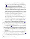
Use this procedure to remove or replace the air moving device (amd) - b03 in the models 270, 800, and 810. The models 270, 800, and 810 may be housed in a fc 0551 frame. The upper and lower system units are placed on rails in the frame. If you are working on the upper or lower unit, follow these ins...
Page 17
Attention: all cards are sensitive to electrostatic discharge. See work with electrostatic discharge-sensitive parts. Attention: if removing the cover while powered on, errors may occur due to electromagnetic interference. The model 270 or 810 may be housed in a fc 0551 frame. The upper and lower sy...
Page 18
Models 270, 800, and 810 - cards (dedicated) for use by authorized service providers. Use this procedure to remove or replace cards using dedicated maintenance on the models 270, 800, and 810. The models 270, 800, and 810 may be housed in a fc 0551 frame. The upper and lower system units are placed ...
Page 19
The models 270, 800, and 810 may be housed in an fc 0551 frame. The upper and lower system units are placed on rails in the frame. If you are working on the upper or lower unit in a 0551 frame, follow these instructions and access the internal parts by opening the front cover and sliding the system ...
Page 20
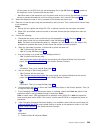
2. Push the cover toward the back of the system to remove it. To remove the top cover: 1. Remove all of the previous covers. 2. Remove the screws that fasten the cover to the system frame. 3. Slide the top cover back and lift up. Models 270, 800, and 810 - device board - db1, db2, and db3 for use by...
Page 21
V yes: after you have determined the location of the disk unit to replace, remove the covers. See models 270, 800, and 810 - covers. Then, continue with the next step. V no: go to recovery procedures. 3. Remove the emc access plate that is over the disk unit that you are removing. For location infor...
Page 22
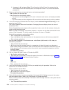
Wait another five seconds to allow time for the disk to stop spinning. Then, pull the disk unit out the remaining way. 6. Are you finished with the repair? V no: continue with the next step. V yes: replace the covers that were removed during this procedure and return to the procedure that sent you h...
Page 23
Models 270, 800, and 810 - disk unit (dedicated) for use by authorized service providers. Use this procedure to remove or replace a disk unit using dedicated maintenance on the models 270, 800, and 810. The models 270, 800, and 810 may be housed in a fc 0551 frame. The upper and lower system units a...
Page 24
V no: continue with the next step. V yes: replace the covers that were removed during this procedure and return to the procedure that sent you here. This ends the procedure. 5. To install a disk unit using dedicated maintenance, perform the following: a. Power off the system. See power on/off the sy...
Page 25
Models 270, 800, and 810 - power supply - p01 for use by authorized service providers. Use this procedure to remove or replace the power supply - p01 on models 270, 800, and 810. The models 270, 800, and 810 may be housed in an fc 0551 frame. The upper and lower system units are placed on rails in t...
Page 26
3. Remove the left side cover. See models 270, 800, and 810 - covers. 4. Remove the emc shield by pulling out on the two side latches. 5. Unlatch the processor card and pull it towards you to remove it from the system. 6. If the processor card has memory dimms on it you must move the memory dimms to...
Page 27
5. Pull the side fasteners to release the media tray from the system frame. 6. Remove the media unit and tray from the frame by sliding it forward. 7. Reverse these steps to install the new device. Notes: v if you need to remove a tape from the old tape unit, see tape cartridge - manual removal. V i...
Page 28
– 96: model 270 with processor ccin 24a0, 24a2, 24a4, 25bd and with fc 7104, (with removable processor) v for models 800 and 810: – 91: models 800 and 810 with ccin 25b9, 25ba, 25f0 and without expansion unit (fc 7116), (without removable processor) – 92: model 810 with processor ccin 25eb and witho...
Page 29
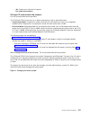
Model 820 - control panel - nb1 model 820 - covers model 820 - device board - db1 and db2 model 820 - disk unit (concurrent) model 820 - disk unit (dedicated) model 820 - memory model 820 - power supply - p01, p02, and p03 model 820 - processor - m03 model 820 - processor regulator - m03 model 820 -...
Page 30
Model 820 - cards (concurrent) for use by authorized service providers. Use this procedure to remove or replace cards concurrently in the model 820. Concurrent/dedicated guidelines for model 820 in some cases, you do not need to power down the system to change pci cards. Use the following guidelines...
Page 31
To replace cards (concurrently): 1. Install the card in to the system by reversing the card removal procedure above. 2. Select power on domain for the ioa or iop that you are installing. 3. Press enter. The work with controlling resources display will appear. Note: to the right of the description fi...
Page 32
The 16-digit world-wide port-name can also be determined by appending the digits ″1000″ to the beginning of the 12-digit ieee address found on the tailstock label of the fibre channel ioa. Use the ess web interface user’s guide (sc26-7346) to update the world-wide port-name in the host configuration...
Page 33
G. Depress the push button for 3-4 seconds. 13. After exchanging an item, go to verify the repair. This ends the procedure. Model 820 - covers for use by authorized service providers. Use this procedure to remove or replace covers on the model 820. Attention: if removing the cover while powered on, ...
Page 34
V yes: after you have determined the location of the disk unit to replace, remove the front covers for access. (see “model 820 - covers” on page 21.) continue with the next step. 3. Remove the emc access plate that is over the location of the disk unit that you are removing. For location information...
Page 35
B. Select start a service tool—>hardware service manager—>device concurrent maintenance and enter the required information in the information fields. Do not press the enter key at this time. C. Slide the unit half-way into the tower. Attention: ensure that the device does not contact the backplane a...
Page 36
5. Are you finished with the repair? V no: continue with the next step. V yes: replace the covers that were removed during this procedure and return to the procedure that sent you here. This ends the procedure. 6. To install a disk unit using dedicated maintenance, perform the following: a. Power of...
Page 37
6. Remove the memory dimms from the processor or memory riser card by pressing down on the latches that are on each end of the dimm. 7. If you are replacing the memory riser card, then you must move the memory dimms to the new card. 8. Install the new memory dimms by firmly pressing the dimm on to t...
Page 38
Note: the processor regulator is part of the processor card assembly (m03). To remove or replace the processor regulator - m03: 1. Power off the system. (see “power on/off the system and logical partitions” on page 561.) 2. Unplug the power cord from the back of the system unit. 3. Remove the left s...
Page 39
To remove or replace the system unit backplane (mb1) and power distribution board (pb1): 1. Power off the system. See power on/off the system and logical partitions. 2. Unplug the power cord from the back of the system unit. 3. Remove the following: a. The right side cover. See model 820 - covers. B...
Page 40
F. Locate the push button located on the back of the control panel, directly behind the keystick position, and depress it for 3-4 seconds. 7. Select function 7 on the system control panel. Press enter. (07** will be displayed) 8. Use the arrow keys to increment/decrement to sub-function a9 (07a9 wil...
Page 41
To remove or replace the time of day battery: 1. Power off the system and unplug ac power cable. See power on/off the system and logical partitions. 2. Remove the left side cover. See model 820 - covers. 3. Remove the cover (emc shield) by pulling out on the two latches. The latches are located on e...
Page 42
Use this procedure to remove or replace the air moving device (amd) - b01; b02 (concurrently) on a model 825. Two amds (excluding the amds mounted on the power supplies), and two power supplies must be installed to perform this procedure. Attention: the replacement fan must be reconnected within 30 ...
Page 43
Attention: all cards are sensitive to electrostatic discharge. See work with electrostatic discharge-sensitive parts. Attention: if removing the cover while powered on, errors may occur due to electromagnetic interference. To remove cards concurrently: 1. In some cases you do not need to power down ...
Page 44
4. After replacing a part, go to verify the repair. This ends the procedure. Model 825 - cards (dedicated) for use by authorized service providers. Use this procedure to remove or replace cards using dedicated maintenance in the model 825. Attention: all cards are sensitive to electrostatic discharg...
Page 45
8. After replacing a part, go to verify the repair. This ends the procedure. Model 825 - control panel - nb1 for use by authorized service providers. Use this procedure to remove or replace the control panel - nb1 in a model 825. Attention: the control panel is sensitive to electrostatic discharge. ...
Page 46
12. If you are here to replace a processor capacity card that was associated with processor-on-demand (pod) processor features, perform the following: a. Contact your second level of support to determine if a pod activation code is required to reset previously activated on-demand processors. B. If n...
Page 47
4. Remove the optical and tape units from the cage assembly. See model 825 - removable media - d17 and d18. 5. Remove the screws holding the front of the cage assembly to the front of the system unit frame. 6. Remove the screws from the back inside of the cage assembly. 7. Remove the air flow shield...
Page 48
4. Are you removing or installing a disk unit using concurrent maintenance? V yes: continue with the next step. V no: perform model 825 - disk unit (dedicated). 5. To remove a disk unit using concurrent maintenance, perform the following: a. Select system service tools (sst). If you cannot get to ss...
Page 49
C. Select device concurrent maintenance and enter the required information in the information fields. Do not press enter at this time. D. Slide the unit half-way in. Attention: ensure that the device does not contact the backplane at this time. E. Press enter on the console. After the delay time, th...
Page 50
Figure 1. Removing a disk unit (dedicated) 4. Are you finished with the repair? V no: continue with the next step. V yes: replace the covers that were removed during this procedure and return to the procedure that sent you here. This ends the procedure. 5. To install a disk unit using dedicated main...
Page 51
5. Are you removing mb1? V no: continue with step 6 (see page 39). V yes: perform the following: a. Remove any cables from mb1, and note the locations. B. Remove the small cover on the top rear of the frame by pulling the locking button out and sliding the cover to the rear and up. See model 825 - c...
Page 52
5. Remove the processor card cage cover. 6. Remove the processor card or cards. 7. Remove the processor card cage. Figure 2. Processor card cage and pci tailstock support bracket 40 hardware (remove and replace; part locations and listings).
Page 53
8. Remove the screw that attaches the interlock switch to the top of the frame. 9. Disconnect the two wires attached to the switch. 10. Install the new part by reversing this procedure. This ends the procedure. Model 825 - memory - a through h for use by authorized service providers. To remove or re...
Page 54
4. Remove the disk units from the system. Identify each disk unit with a disk unit board location and slot location. 5. Remove the four short screws on the perimeter of the disk unit board/cage aassembly and the two longer screws located inside the assembly. 6. Partially remove the disk unit board/c...
Page 55
5. Lift the handle all the way up and towards you. 6. Remove the power supply by sliding it out of the system. 7. Install the power supply by reversing this procedure, ignoring step 1. After exchanging an item, go to verify the repair. This ends the procedure. Model 825 - removable media - d17 and d...
Page 56
5. Perform the following: a. Select system service tools (sst). If you cannot get to sst, select dst. Do not perform a system ipl to get to dst. B. Select start a service tool —> hardware service manager —> device concurrent maintenance and enter the required information in the information fields. D...
Page 57
V yes: after exchanging an item, go to verify the repair. This ends the install procedure. 8. There is a power problem. One of the following is the problem: v the new unit is defective. V the backplane was damaged during the device concurrent maintenance procedure. V there is a new problem with the ...
Page 58
6. Unplug the cables that come from the power supply (located on the right side of the system), cables that connect to the disk unit cages, control panel function cables, and the cables running to the rear bulk head (located on the left side of the system). 7. Remove the plastic pci card separators....
Page 59
9. Remove the processor card cage and pci tailstock support bracket. Figure 3. Processor card cage and pci tailstock support bracket analyze hardware problems 47.
Page 60
10. Remove the screws that attach the backplane insulator to the backplane, and remove the insulator. 11. Remove the three small torx screws and two small slotted screws from the upper middle edge of the backplane assembly, that connect the backplane to the power bus bar assembly. 12. Remove the bac...
Page 61
C. Use the arrow keys to increment/decrement to the frame address of the box you just replaced the backplane (usually 01 for the system unit). 07nn will be displayed, where nn is the frame address). D. Press enter (07nn 00 will be displayed). E. Use the arrow keys to increment/decrement to the corre...
Page 62
Models 830/sb2 - device boards - db1 and db2 models 830/sb2 - device board - db3 models 830/sb2 - disk unit models 830/sb2 with fc 9074 - system unit control panel - nb1 models 830/sb2 with fc 9074 - power distribution backplane - pb1 models 830/sb2 with fc 9074 - power supply - pp1 and pp2 models 8...
Page 63
5. Disconnect the power supply jumper cords from the ac module that you are working on. Attention: do not disconnect the other system ac module power supply jumper cords. 6. Remove the top and bottom screws that hold the ac module to the frame. 7. Remove the ac module unit. 8. Install the ac module ...
Page 64
In the united states, ibm has a process for the collection of this battery. For information, call 1-800-426-4333. Have the ibm part number for the battery unit available when you call. (rsftc225) 4. Install the battery pack by reversing the removal procedure. After exchanging an item, go to verify t...
Page 65
2. Select hardware contained in packaging for the frame id that you are working on. 3. Find the card position for the ioa or iop that you are removing and select concurrent maintenance. Attention: if multiple resources are shown with the same card position, one or more of these resources will show a...
Page 66
Models 830/sb2 with fc 9074 - cards (dedicated) for use by authorized service providers. Use this procedure to remove or replace cards dedicated in the models 830/sb2 with an fc 9074. In some cases you do not need to power down the system to change pci cards. Use the guidelines in models 830/sb2 wit...
Page 67
V if you are removing a memory riser card (m02 or m05) or the dimms in a model 830/sb2 system unit, go to step 7 (see page 55). V if you are removing the network interface controller (nic) card (m06) or the clock card (m06a) from the nic controller card on a model 830/sb2 system unit, go to step 8 (...
Page 68
J. After exchanging an item, go to verify the repair. This ends the procedure. 9. You are removing a processor card assembly (m03 or m04) in a model 830/sb2 system unit. Refer to figure 2. In final assembly, rear - models 830 and sb2 with fc 9074 (see page 403), and perform the following steps: atte...
Page 69
3) starting with the brush in the center of the processor contact surface that is on the system backplane, use an outward brushing motion to clear the debris away from the area where the surfaces of the processor module assembly and the system backplane assembly meet. Be careful not to brush over th...
Page 70
J. While grasping the center of the new processor, orient the side of the assembly with the square notch towards the latching arm, which is on your left when facing the rear of the tower. Align the holes in the processor assembly with the guide pins on the board and press down until it is fully seat...
Page 71
Figure 1. Front cover - removal 1. Unlock the cover. 2. Release the cover latching mechanism by pushing in on the button a that is located midway along the right edge of the cover. 3. Grasp the top, right corner of the cover and pull it towards you to open it. 4. After opening the cover, press down ...
Page 72
2. Disconnect the power cord from the system unit. 3. Open the front cover. (see “models 830/sb2 with fc 9074 - covers” on page 58.) refer to final assembly, front - models 830 and sb2 with fc 9074 (see page 400) and perform the following steps. 4. From the front of the system do the following: a. R...
Page 73
8. Remove the dasd board assembly. 9. Install the dasd board assembly by reversing the removal procedure. After exchanging an item, go to “verify the repair” on page 558. This ends the procedure. Models 830/sb2 - device board (db3) for use by authorized service providers. Use this procedure to remov...
Page 74
9074 base i/o tower” on page 260. Press the surfaces of the two latching mechanisms together and tilt the top of the cover away from the frame to remove it. G. Record the disk unit locations and then remove them from the disk unit enclosures that you just uncovered. Attention: the disk units are sen...
Page 75
D. Press enter on the console. After the delay time, the light above the device location will begin flashing. You now have nine seconds to pinch the two surfaces of the latching mechanism together and rotate the handle of the disk unit towards you. Pull the disk unit out part way. The light above th...
Page 76
Into the slot and rotate the handle towards the disk unit to latch it into the slot. The light above the device location will go off and remain off for a few seconds when the device contacts the backplane. Then it should go on and remain on. Attention: if you install the device when the light is not...
Page 77
7. Remove the control panel from the frame. 8. Loosen the two screws that retain the processor capacity card retention (back) cover and remove the cover. 9. If you are replacing the panel, then you must move the processor capacity card and interactive card to the new panel. Important: mark the proce...
Page 78
A. Apply ac power. B. Insert the new keystick into the panel. The control panel will display 0000 5553 . C. Locate the push button that is on the back side of the control panel. It is located directly behind the keystick. D. Depress the push button for 3-4 seconds. E. The control panel will return t...
Page 79
5. Remove the three power supplies. (see “fc 5074, fc 5079, fc 9074, fc 9079 - power supply - p00, p01, p02, and p03” on page 149.) 6. Remove the four batteries (see models 830/sb2 with fc 9074 - battery - t01 through t04). 7. Remove the screws from the power subframe assembly. 8. From the front of ...
Page 80
3. Unplug the power supply cable. Refer to “final assembly, rear - models 830 and sb2 with fc 9074” on page 401 and continue with the following steps. 4. Remove the mounting screw from the power supply. 5. Rotate the handle from left to right to release the power supply from the frame. 6. Remove the...
Page 81
1. Determine if the system has logical partitions. Go to determine if the system has logical partitions before continuing with this procedure. 2. Remove media (if any) from the device. If the eject button on a tape device is failing, go to tape cartridge - manual removal, then continue with the next...
Page 82
F. Remove the unit from the tower. Notes: v if you need to remove a tape from the old tape unit, see tape cartridge - manual removal. V if you need to remove optical media from a dvd-ram unit, go to optical media - manual removal, and then continue with the next step of this procedure. This ends the...
Page 83
5. Remove the mounting screws from the emc shield that is covering the processor/cec cage assembly. 6. Remove the emc shield. 7. Remove the mounting screws from the processor/cec cage assembly. 8. Remove the emc access plate that is located directly above the pci cage (cb1). 9. Reach under the proce...
Page 84
D. Pull the pci card enclosure partially out of the frame to the release mechanism stop on the right side, while lifting the cables clear of the enclosure. E. The battery is located on the right hand side of the pci enclosure. Remove the pci cards preventing access to the battery from the enclosure ...
Page 85
Note: the tower may power up automatically. B. Power down the expansion tower without removing the power cord using the expansion unit power procedure. Then, return here and continue with step 10c. C. Select function 07 on the system control panel. Press enter (07** will be displayed). D. Use the ar...
Page 86
Models 840/sb3 - time of day (tod) battery models 840/sb3 processor tower (with non-dual line cords) - ac box (a01) for use by authorized service providers. Use this procedure to remove or replace the ac box (a01) in a model 840/sb3 processor tower (with non-dual line cords). To remove or replace th...
Page 87
Use this procedure to remove or replace the ac module (a01, a02) on the model 830 with fc 9074, or model 840 with fc 9079 or fc 8079 (with dual line cords). To remove or replace the ac module (a01, a02): 1. Do not power down the tower if it is powered on. This procedure can be done concurrently. 2. ...
Page 88
C. Use the arrow keys to increment/decrement to the frame address of the processor tower, usually ’02’ (0702 will be displayed). Press enter (0702 00 will be displayed). D. Use the arrow keys to increment/decrement to select 07fx where x is the amd to be powered off (0=amd b01, 1=amd b02, 2=amd b03,...
Page 89
No card positions in the cec permit concurrent maintenance. You must power down the system to exchange a card. See models 840/sb3, fc 8079-001 (lower half), fc 9079 cards (dedicated). For fc 9079 i/o tower ixs cards: the ixs cards require dedicated maintenance. See models 840/sb3, fc 8079-001 (lower...
Page 90
C. Remove the mounting screws from the card enclosure. See final assembly, rear - models 840 and sb3 processor tower. D. Slide the card enclosure partially out of the frame. E. Disconnect and label any cables from the card that you wish to remove. F. Turn the latch counter clockwise and lift up on t...
Page 91
3. Choose one of the following: v if you are removing a processor capacity card card or an interactive card from the processor tower display panel, then go to model 840/sb3 processor tower, fc 8079-001 (lower half), and fc 9079 - control panels (nb1). V if you are removing cards in a fc 9079 or the ...
Page 92
Models 840/sb3 system unit - charger (g01) for use by authorized service providers. Use this procedure to remove or replace the charger (g01) in a model 840/sb3 system unit. To remove or replace the charger (g01): 1. Do not power off the system. 2. Remove the rear cover. (see “models 840/sb3 - cover...
Page 93
Caution: the circuit card contains lead solder. To avoid the release of lead (pb) into the environment, do not burn. Discard the circuit card as instructed by local regulations. (rsftc234) to remove or replace the control panel (nb1): 1. Power off the system. See power on/off the system and logical ...
Page 94
11. Reverse the above procedure to install the panel. 12. When a control panel with keystick is replaced, discard the new keysticks that come with the panel and reuse the original keysticks. Does the system that you are working on have a keystick lock? V yes: continue with the next step. V no: go to...
Page 95
Note: determine if the system has logical partitions. Go to determine if the system has logical partitions before continuing with this procedure. Attention: the disk unit is sensitive to electrostatic discharge (see work with electrostatic discharge-sensitive parts). 1. Were you directed here from r...
Page 96
Wait another five seconds to allow time for the disk to stop spinning. Then pull the disk unit out the rest of the way. 2. Are you finished with the repair? V no: continue with the next step. V yes: replace the covers that were removed during this procedure and return to the procedure that sent you ...
Page 97
1. To remove a disk unit using dedicated maintenance perform the following: a. Power off the system. See power on/off the system and logical partitions. B. Disconnect the power cord. C. To remove the disk unit, pinch the two surfaces of the latching mechanism together and pull the handle towards you...
Page 98
To remove or replace the power subframe assembly (pb1): 1. Print out a rack configuration sheet so that you know where all devices and cards are located in the system rack. 2. Power the off system. See power on/off the system and logical partitions. 3. Disconnect the ac power cord. 4. Remove the fro...
Page 99
Danger up to 240 v ac is present at the power module connectors when the main power cord is connected to a power source. (rsftd010) to remove or replace the power supply (p01 through p06): 1. Do not power off the system. Attention: remove and replace only one power supply at a time. 2. Remove the fr...
Page 100
V yes: continue with the next step. V no: perform the following: a. Power off the tower or expansion tower. See power on/off the system and logical partitions. B. Disconnect the power cord from the tower or expansion tower. C. Open the front cover. See fc 5074, fc 5079, fc 5094, fc 5294, fc 9079, fc...
Page 101
1. Perform the following to install a new unit. A. Select device concurrent maintenance and enter the required information in the information fields. Do not press the enter key at this time. B. Read the remaining steps of this procedure and ensure that you understand the procedure before continuing....
Page 102
6. Rotate the latches out. 7. Pull on both latches at the same time to remove the card from the slot. 8. Install the new spcn card by reversing the removal procedure. After exchanging an item, go to “verify the repair” on page 558. This ends the procedure. Models 840/sb3 - system unit backplane (mb1...
Page 103
Caution: the weight of this part or unit is between 18 and 32 kilograms (39.7 and 70.5 pounds). It takes two persons to safely lift this part or unit. (rsftc204) k. Unplug the cables attached to the lower left and right corners of the front cage/backplane assembly. 7. Refer to “final assembly, front...
Page 104
C. Pull the pci card enclosure partially out of the frame to the release mechanism stop on the right side, while lifting the cables clear of the enclosure. D. Remove the pci cards on the right side of the enclosure preventing access to the battery from the enclosure and note their locations. See fc ...
Page 105
Models 870 and 890 - mda (air mover) controller models 870 and 890 - memory books and memory blanks models 870 and 890 - motor scroll assembly (msa) air filters models 870 and 890 - msa (air mover) enclosure models 870 and 890 - network interface controller (nic) card models 870 and 890 (fc 9094) - ...
Page 106
To replace the bulk power controller (bpc): 1. Ensure that all of the bpr’s on-lock/off-unlock switches are in the off position on this bpa before proceeding. 2. Slowly slide the unit into the slot and seat it carefully against the backplane, avoiding damage to the connectors. 3. Tighten the left an...
Page 107
Models 870 and 890 - bulk power enclosure (bpe) for use by authorized service providers. Use this procedure to remove or replace the bulk power enclosure (bpe) on the models 870 and 890. To remove the bulk power enclosure (bpe): 1. Locate the bpe to be replaced by decoding the src. See the system re...
Page 108
1. Do not power down the system if it is powered on; this procedure can be done concurrently. 2. Open the cover so that you can access the field replaceable unit (fru). See models 870 and 890 - covers. 3. Locate the bpf to be replaced by decoding the src (see system reference codes), or see location...
Page 109
3. Perform the following: a. Tighten the left thumb screw four turns with the torque tool (pn 6422789). Then, tighten the right thumb screw four turns. B. Torque the left thumb screw to completion, followed by the right thumb screw. C. Return to the left thumb screw and assure it is torqued. D. Make...
Page 110
1. Unlock the latch on the cover. Figure 1. Models 870 and 890 cover latch 2. Depress the button on the bottom of the latch mechanism to open the cover. 3. Lift the cover to remove it, if necessary. 4. Reverse the above procedure to install the covers. This ends the procedure. Models 870 and 890 - d...
Page 111
2. Open the rear cover to access the field replaceable unit (fru). See “models 870 and 890 - covers” on page 97. 3. Locate the dca to be replaced by decoding the src (see the system reference codes topic). 4. Note the state of the dca’s leds. Then, press the (green) start service button and only pro...
Page 112
Attention: the l3 modules in this system can be attached to the backplane a maximum of three times. If an l3 module is removed for a fourth time, it must be replaced with a new l3 module. Check the mcm/l3 label map to determine how many times the module has been removed before. New l3 cache modules ...
Page 113
7. Slide both plates up and pull them away from the l3 module. 8. Pull the sleeves off the posts. 9. Use a disposable lint-free cloth to clean the sleeves. 10. Pull the l3 module straight back off the posts and place it with the lga connector down in the four position tray from the tool kit. Figure ...
Page 114
11. Record on the log sheet on the system the date that this l3 has been removed. To return l3 modules: the following procedure provides handling instructions for l3 modules to be packaged and returned to the plant of manufacture. 1. If you are replacing an l3 module, use the packaging from the new ...
Page 115
Attention: each time an l3 module is installed on the system board, the lga site where the module connects with the system board must be cleaned. With the brush supplied with the replacement kit, use only downward strokes, starting in the upper left corner. Move left to right, top to bottom, using o...
Page 116
V figure 6. Missing buttons. 6. Align the flat corner on the l3 module to match the outline on the system board. 7. Carefully slide the l3 module straight onto the posts until it meets the system board. 8. If you are installing a new l3 module, replace the sleeves that you removed earlier with the n...
Page 117
9. Use a 5mm socket wrench to tighten the set screw in the center of the l3 module spring plate until it is seated. Check the l3 module short-circuit test tool to ensure that short circuit was not created when the l3 cache module was installed. If this is the last l3 cache module you are installing,...
Page 118
V do not remove the device from the antistatic container until you are ready to install the device in the system unit. V with the device still in its antistatic container, touch it to a metal frame of the system. V grasp modules by the heatsink. Avoid touching the interposer buttons. V if you need t...
Page 119
8. Use an 8mm socket to loosen the actuation bolt in center of the mcm module. (a 5mm socket must be used if removing the protective lga cover). If installing a new mcm, remove the actuation bolt. 9. If installing a new mcm, insert the new actuation bolt supplied with the new mcm module. 10. Move th...
Page 120
13. Record on the log sheet on the system the date that this mcm has been removed. To install mcm and pass-through modules: note: this procedure is to be performed only by trained service personnel. 1. Power off the system, and unplug the power cord. 2. If installing a new mcm module, insert the new...
Page 121
4. Remove the cover from the new mcm module. See models 870 and 890 - mcm and pass-through modules - remove protective covers. Figure 4. Mcm module alignment 5. Each time an mcm module (or pass-through) is installed on the system board, the associated interposer must be inspected. Inspect the mcm in...
Page 122
V figure 6. Missing buttons. 6. Verify all four posts on mcm module are snug prior to installing on the backplane. A loosened guide post can be tightened with a ratchet or wrench until it is snug. Use caution not to damage the interposer. 7. Perform the following, paying close attention: a. Grasp th...
Page 123
13. If you are replacing a processor capacity card that was associated with processor-on-demand (pod) processor features, perform the following: a. Contact your second level of support to determine if a pod activation code is required to reset previously activated on-demand processors. B. If necessa...
Page 124
3. Find the location of the mda to be replaced in locations - models 870 and 890. 4. Note the state of the mda’s led. Then, press the (green) start service button on the uepo panel. 5. Proceed only if the mda led is off, or the repair has been scheduled (system outage - epo off). 6. Loosen the thumb...
Page 125
Models 870 and 890 - msa (air mover) enclosure for use by authorized service providers. Use this procedure to remove or replace the motor scrolling assembly (msa) enclosure on the models 870 and 890. To remove or replace the msa enclosure: 1. Power off the system. See power on/off the system and log...
Page 126
1. Inspect the new nic card for damage. See “inspect the network interface controller (nic) card” on page 113 above. 2. Unlatch the handles on the replacement card. 3. Take care not to hit the connector against the cage, which can cause damage to the nic card connectors. 4. Slide the card in until i...
Page 127
Models 870 and 890 - l3 modules - remove the protective cover models 870 and 890 - mcm and pass-through modules - remove the protective cover models 870 and 890 - remove and replace tools models 870 and 890 - shorts test qualified service meters and fail criteria models 870 and 890 - testing mcms an...
Page 128
2. Manually loosen the two thumb screws, ensuring that both screws are completely loose from the module base before proceeding. Figure 2. Loosen the thumb screws 116 hardware (remove and replace; part locations and listings).
Page 129
3. At this point, the cover can be removed from the module to expose the interposer. 4. To remove the cover from the bottom half of the interposer, perform the following: a. Place the module on the esd mat. B. Place your thumb over one of the release latches and your forefinger over the opposite lat...
Page 130
C. Squeeze the latches, and at the same time, pull the cover from the interposer. Figure 4. Pulling the cover from the interposer 118 hardware (remove and replace; part locations and listings).
Page 131
This ends the procedure. Models 870 and 890 - mcm and pass-through module - remove protective covers: for use by authorized service providers. Use this procedure to remove the mcm and pass-through module covers on the models 870 and 890. To remove the mcm or pass-through module protective cover: imp...
Page 132
3. Loosen until all load is removed and the spring plate is free to rotate. 4. Rotate the spring plate counter-clockwise to align the four large keyhole openings with the posts present on the module. Figure 2. Rotating the spring plate on the module 5. Carefully remove the cover from the module to e...
Page 133
6. Place the cover side-down on the esd mat. Important: do not place the lga cover face down on the esd mat, because this may introduce contamination to the lga cover surface. 7. At this point, the cover can be removed from the module to expose the interposer. 8. Verify that all four guide posts are...
Page 134
Part number units per assembly description 11p4861 1 blank cassette 11p3990 1 door key 44p0182 1 dasd service tool 11p4914 1 mcm/l3/pass-through plug location map (tri-fold chart): should be installed in the primary rack. 11p4055 n/a plug count adhesive replacement label 44p209 1 test card assembly ...
Page 135
Manufacturer model range (ohm) accuracy at 1.0 ohm or less fail criteria (ohm) fluke 10 400 +/-0.20 +0.50 fluke 11 400 +/-0.20 +0.50 fluke 110 600 +/-0.20 +0.50 fluke 111 600 +/-0.20 +0.50 fluke 112 600 +/-0.20 +0.50 fluke 12 400 +/-0.20 +0.50 fluke 12b 400 +/-0.20 +0.50 fluke 16 400 +/-0.20 +0.50 f...
Page 136
Determining the test method: there are two shorts test procedures you can use depending on the test hardware you have. “test method 1: testing mcm and passthru modules for a short circuit using a new capacitor book and automated shorts tester” - use a new capacitor book and the lga shorts tester for...
Page 137
Table 2. Check lga-st for the ability to detect passing conditions rocker switch position mcm green led mcm amber led l3 green led l3 amber led battery low amber led note forward mcm/l3 pwr/gnd on off on off off 1. If battery low led is on, or if no leds are lit, replace the battery before proceedin...
Page 138
5. Install an l3 module. 6. Press the rocker switch forward to the mcm/l3 pwr/gnd position. This checks the l3s for power to ground shorts. It also checks the mcm for power to ground shorts. Note the following: v the green l3 led must be lit for a pass condition. If the amber l3 is lit, there may be...
Page 139
V if you are using the short-circuit test option: install the test card in dca location 6 (m38), with no meter attached. 5. Wait one minute to allow any charge to dissipate. 6. Select the meter to be used for this test. Meters recorded in the qualified meters table are to be used, see shorts test qu...
Page 140
V no: reject the mcm/passthru module. Install another mcm/passthru (m21, m16, m11, m14), and go to step 1 (see page 127). 7. Inspect the interposer for shorts. 8. Are there any shorts visible? V yes: reject the mcm/passthru module and install another one (m21, m16, m11, m14), and go to step 1 (see p...
Page 141
V no: install the first l3 cache module (m03, m04, m09, m10) (m12, m13, m05, m06) (m22, m23, m28, m29) (m26, m27, m19, m20), working v top to bottom. Then, continue with l3 cache testing, procedure 2 (see page 129). L3 cache shorts test, procedure 2 1. Choose from the following options: v if you are...
Page 142
5. Are all the memory and nic cards disengaged? V no: continue with the next step. V yes: do not power on the system. Contact your next level of support. This ends the procedure. 6. Are all the memory disengaged? V no: disengage a memory book (memory is removed one at a time). Then, go to step 2 (se...
Page 143
V no: reinstall the l3 cache module and go to l3 cache testing, procedure 2 (see page 129). V yes: reject the l3 cache module, and install another l3 cache module. Then, go to l3 cache testing, procedure 2 (see page 129). L3 cache shorts test, procedure 5 do mcm modules need to be installed? V yes: ...
Page 144
Book, and lift place assembly tool, pn 11p4369. V all components must be removed from the system unit backplane to reduce its weight to a minimum. – dca books and dca blanks – capacitor books – network interface controller (nic) card – memory books and memory blanks – processor msa (air mover) assem...
Page 145
18. Remove the uepo switch. See models 870 and 890 - unit emergency power off (uepo) card assembly. 19. Remove the screws attaching the chassis to the vertical eia rails at the front and rear, using an 8mm extension socket. Note: rear screws also remove mounting brackets. 20. At the back of the syst...
Page 146
2. Press the (green) start service button (number 10 in figure 1) on the uepo assembly. 3. Switch the uepo bypass switches on both bpcs to the bypass position (to the right). Figure 1. Uepo card assembly 4. Ensure that the red switch (number 8 in figure 1) on the front of the epo panel is in the on ...
Page 147
Note: the mcm module and its associated vpd card are a single field replaceable unit (fru), and must be replaced as a set. There is only one vpd card for all of the l3 modules. Replacing any l3 module requires replacing the associated vpd card. To remove or replace the vpd card: note: the vpd cards ...
Page 148
V e = 16-way vpd v f = 24-way vpd v g = 32-way vpd 3. Locate the card that must be replaced. 4. Remove the card, and if it is a vpd card, the associated mcm or l3 modules. 5. Replace the card in reverse order (and if it is a vpd card, the new mcm or l3 modules). 6. Perform a manual ipl to dst. If th...
Page 149
Fc 5074, fc 5079, fc 9079 - removable media - d41 and d42 fc 5074, fc 5079, fc 9079 - tower card - cb1 fc 5074, fc 5079, fc 9079 (single line cord) - ac charger - a01 for use by authorized service providers. Use this procedure to remove or replace the ac charger - a01 in the fc 5074, fc 5079, or fc ...
Page 150
3. Remove the emc access plate located directly above the pci card enclosure. Press the surfaces of the two latches together and tilt the top of the cover away from the frame to remove it. 4. Remove the screw from the amd door assembly for the amd that you are replacing. 5. Remove the amd assembly b...
Page 151
Use concurrent maintenance on a partitioned system, follow the procedures from the partition that owns the resource. If the resource is not owned, follow the procedure from the primary partition. For fc 5074, fc 5079, fc 5094, or fc 5294 ixs cards: the ixs cards require dedicated maintenance. Do not...
Page 152
9. Remove the emc access plate that is located directly above the card enclosure. Press the two latching mechanisms together and tilt the top of the cover away from the frame to remove it. 10. Look at the power led for the card that you are removing to ensure that it is powered off. The power led is...
Page 153
1. Power off the expansion unit. See the expansion unit power procedure. 2. Remove the ac power cord from the frame that you are working on. 3. Remove the cover to access the card that you are removing from the system. See fc 5074, fc 5079, fc 5094, fc 5294, fc 9079, or fc 9094 - covers. 4. Remove t...
Page 154
Figure 2. Rear cover - removal fc 5074, fc 5079, fc 9079 - device board - db1 and db2 for use by authorized service providers. Use this procedure to remove or replace the device board - db1 and db2 in an fc 5074, fc 5079, or fc 9079. 142 hardware (remove and replace; part locations and listings).
Page 155
To remove or replace the device board (db1 and db2): 1. Power off the expansion tower (see power on/off the system and logical partitions). 2. Disconnect the power cord from the expansion tower. 3. Open the front cover. See fc 5074, fc 5079, fc 5094, fc 5294, fc 9079, fc 9094 - covers. 4. From the f...
Page 156
7. Remove the dasd board assembly. 8. Install the dasd board assembly by reversing the removal procedure. After exchanging an item, go to verify the repair. This ends the procedure. Fc 5074, fc 5079, fc 9079 - device board - db3 for use by authorized service providers. Use this procedure to remove o...
Page 157
G. Record the disk unit locations and then remove them from the disk unit enclosures that you just uncovered. Attention: the disk units are sensitive to electrostatic discharge (see work with electrostatic discharge-sensitive parts). H. Remove the screws that hold the disk unit enclosures to the fra...
Page 158
Wait another 5 seconds to allow time for the disk to stop spinning. Then pull the disk unit the remaining way out of the tower. 5. Are you finished with the repair? V no: continue with the next step. V yes: replace the covers that were removed during this procedure and return to the procedure that s...
Page 159
Fc 5074, fc 5079 - disk unit (dedicated) for use by authorized service providers. Use this procedure to remove or replace the disk unit (dedicated) in an fc 5074 or fc 5079. Attention: the disk unit is sensitive to electrostatic discharge (see work with electrostatic discharge-sensitive parts). To r...
Page 160
V yes: replace the covers that were removed during this procedure and return to the procedure that sent you here. This ends the procedure. 6. Install the disk unit by performing the following: a. Power off the system (see power on/off the system and logical partitions). B. Disconnect the power cord....
Page 161
D. Remove the screws that hold the pci card enclosure to the frame. E. Pull the pci card enclosure partially out of the frame while lifting the cables clear of the enclosure. F. Press the release mechanism that is located along the top right side of the enclosure and carefully slide the enclosure to...
Page 162
Use this procedure to remove or replace the power supply - p00, p01, p02, and p03 in the fc 5074, fc 5079, fc 9074, fc 9079. To remove or replace the power supply - p00, p01, p02, and p03: 1. Is the system powered on? V yes: do not power off the system. Continue with the next step. V no: continue wi...
Page 163
To remove the removable media - d41 and d42: 1. Determine if the system has logical partitions. Go to determine if the system has logical partitions before continuing with this procedure. 2. Remove media (if any) from the device. If the eject button on a tape device is failing, go to tape cartridge ...
Page 164
Note: the light at the top right of the device will go off and remain off as soon as the device is no longer making contact with the backplane. E. Remove the unit from the tower. V if you need to remove a tape from the old tape unit, see tape cartridge - manual removal. V if you need to remove optic...
Page 165
A. Remove the external cables from the rear of the pci card enclosure and note their locations. B. Remove the emc access plate that is located directly above the pci card enclosure. Press the surfaces of the two latching mechanisms together and tilt the top of the cover away from the frame to remove...
Page 166
G. Continue with step 9 (see page 154) to set the configuration id. 8. Perform steps 23 (see page 569) and 24 (see page 570) in the expansion unit power procedure. Then, return here and continue with the next step. 9. Set the configuration id in the tower card: a. If the ac power is not applied, the...
Page 167
H. Power the expansion unit back on. See the expansion unit power procedure. 10. After exchanging an item, go to verify the repair. This ends the procedure. Fc 5075 remove and replace procedures for use by authorized service providers. Fc 5075 - air moving device - b01, b02 fc 5075 - cards (concurre...
Page 168
Fc 5075 - cards (concurrent) for use by authorized service providers. Use this procedure to remove or replace cards (concurrently) in the fc 5075. Concurrent/dedicated guidelines for an fc 5075 in some cases you do not need to power down the system to change pci cards. Use the following guidelines t...
Page 169
Note: to the right of the description field you will see one or both of the following symbols displayed. Symbol indication * indicates the location to which the system will assign the resource. > indicates the location to which the resource was last assigned. 3. Press enter. The work with controllin...
Page 170
Configuration on the ibm 2105 ess. The ess web interface user’s guide can also be found at the following url: http://ssddom02.Storage.Ibm.Com/disk/ess/documentation.Html this ends the procedure. Fc 5075 - covers for use by authorized service providers. Use this procedure to remove or replace the cov...
Page 171
3. After you have determined the location of the disk unit to replace, remove the front covers for access. See fc 5075 - covers. 4. Remove the emc access plate that is over the location of the disk unit that you are removing. For location information, see “locations — fc 5075 expansion i/o tower” on...
Page 172
B. Select start a service tool—>hardware service manager. C. Select device concurrent maintenance and enter the required information in the information fields. Attention: do not press enter at this time. D. Slide the unit half-way into the tower. Ensure that the device does not make contact with the...
Page 173
6. Are you finished with the repair? V no: continue with the next step. V yes: replace the covers that were removed during this procedure and return to the procedure that sent you here. This ends the procedure. 7. To install a disk unit using dedicated maintenance perform the following: a. Power off...
Page 174
7. Remove the display panel. 8. Install the display panel by reversing this procedure. After exchanging an item, go to verify the repair. This ends the procedure. Fc 5075 - power distribution board - pb1 for use by authorized service providers. Use this procedure to remove or replace the power distr...
Page 175
3. Remove the front and right side covers. See fc 5075 - covers. 4. Disconnect the control panel cable and the cable that connects the backplane to the backplane cb1. 5. Disconnect the spcn and power cables. 6. Remove the screws connecting the backplane to the frame. 7. Remove the backplane by pulli...
Page 176
A. If the ac power is not applied, then apply it now. Note: the tower may power up automatically. B. Power down the expansion tower without removing the power cord using the expansion unit power procedure. Then, return here and continue with the next step. C. Select function 07 on the system panel. ...
Page 177
5. Remove the power supply that has the defective amd attached by pulling down on the docking handle, and sliding the power supply with the two amds attached out of the expansion unit. 6. Remove the amd from the power supply by pulling out on the latch knob and sliding the amd to the left towards th...
Page 178
– for fc 5088 or fc 0588: card positions c01 through c09 and c11 through c15 permit card level concurrent maintenance using hsm. You can power down the individual card slot. V if the resource is the load source ioa or the load source iop, or any other storage ioa/iop with critical dasd attached for ...
Page 179
16. Determine the location where you want to assign the resource and select assign to for that location. 17. Wait for the hardware resource concurrent maintenance display to appear with the message indicating power on complete. 18. After exchanging the failing item, go to verify the repair. Note: if...
Page 180
The 16-digit world-wide port-name can also be determined by appending the digits ″1000″ to the beginning of the 12-digit ieee address found on the tailstock label of the fibre channel ioa. Use the ess web interface user’s guide (sc26-7346) to update the world-wide port-name in the host configuration...
Page 181
Use this procedure to remove or replace the power distribution board - pb1 in an fc 5078, fc 0578, fc 5088, or fc 0588. To remove or replace the power distribution board - pb1: 1. Remove the top, front, and rear covers. See fc 5078, fc 0578, fc 5088, fc 0588 - covers. 2. Power down the expansion uni...
Page 182
3. Remove the ac power cord from the expansion unit. 4. From the rear of the expansion tower, remove the external cables from the rear of the pci card enclosure and note their locations. 5. Remove the air flow baffle that is located directly above the pci card enclosure. Loosen the three fasteners a...
Page 183
Fc 5094, fc 5294 - cards (dedicated) fc 8094-001 (lower half), fc 9094 - cards (concurrent) fc 8094-001 (lower half), fc 9094 - cards (dedicated) fc 9094 - control panel - nb1 fc 5074, fc 5079, fc 5094, fc 5294, fc 9079, fc 9094 - covers fc 5094, fc 9094 - device board - db1 and db2 fc 5094, fc 9094...
Page 184
8. Install the ac module by reversing this procedure. Note: do not install power supplies p00 and p01 ac jumper cables on the same ac input module. 9. After exchanging an item, go to verify the repair. This ends the procedure. Fc 5094, fc 9094 (with dual line cord) - ac module - a01 and a02 for use ...
Page 185
Concurrent/dedicated guidelines for fc 8094-001 (lower half) and fc 9094 in some cases you do not need to power down the system in order to change pci cards. Use the following guidelines to determine if you should use dedicated or concurrent remove and replace procedures. If you use concurrent maint...
Page 186
5. A listing of the power domain is shown. Select the power off domain function key. Everything within the ioa’s or iop’s power domain will be powered off . 6. To see the status of the power domain, select the display power states function key. 7. Find the ioa or iop that you are removing and select...
Page 187
Caution: the circuit card contains lead solder. To avoid the release of lead (pb) into the environment, do not burn. Discard the circuit card as instructed by local regulations. (rsftc234) attention: all cards are sensitive to electrostatic discharge (see work with electrostatic discharge-sensitive ...
Page 188
B. Slide the panel partially out of the frame. C. Disconnect the cables that are attached to backside of the control panel. D. Remove the control panel from the frame. 5. Reverse the above procedure to install the panel. 6. When a control panel with keystick is replaced, discard the new keysticks th...
Page 189
Fc 5074, fc 5079, fc 5094, fc 5294, fc 9079, fc 9094 - covers for use by authorized service providers. Use this procedure to remove or replace covers on the fc 5074, fc 5079, fc 5094, fc 5294, fc 9079, fc 9094. Note: the front and rear covers will swing open a little more than 90 degrees. This makes...
Page 190
Fc 5094, fc 9094 - device board - db1 and db2 for use by authorized service providers. Use this procedure to remove or replace the device board - db1 and db2 in an fc 5094 or fc 9094. To remove or replace the device board - db1 and db2: 1. Power off the expansion tower. See power on/off the system a...
Page 191
6. Pull the dasd board assembly out until it slides off the guide pins, then rotate the dasd board assembly 90 degrees. Note the locations of the cables that are located on the backside of the board assembly, and then remove them. Note: both ends of the ribbon cables are marked lh or rh, indicating ...
Page 192
Note: both ends of the ribbon cables are marked lh or rh, indicating that one end of the cable is plugged in to either the left-hand (db1) or right-hand (db2) dasd board assembly. The other end of the cable is plugged in to either the left-most (lh) or right-most (rh) dasd controller card. The cable...
Page 193
Attention: if removing the cover while powered on, errors may occur due to electromagnetic interference. Attention: the disk unit is sensitive to electrostatic discharge (see work with electrostatic discharge-sensitive parts). To remove or replace the disk unit using concurrent maintenance: 1. Deter...
Page 194
Wait another five seconds to allow time for the disk to stop spinning. Then pull the disk unit the remaining way out of the tower. 5. Are you finished with the repair? V no: continue with the next step. V yes: replace the covers that were removed during this procedure and return to the procedure tha...
Page 195
A. Power off the system (see power on/off the system and logical partitions). B. Disconnect the power cord. C. Pinch the two surfaces of the latching mechanism together and pull the handle towards you to release the disk unit from the slot. D. Remove the unit from the tower. 5. Are you finished with...
Page 196
To remove or replace the display panel - nb1: 1. Power off the expansion tower. See expansion unit power procedure. 2. Disconnect the ac power cord from the expansion tower. Note that dual line cord units have two power cords. 3. Open the front cover. See fc 5074, fc 5079, fc 5094, fc 5294, fc 9079,...
Page 197
9. Pull the power distribution backplane slightly towards you and lift it up to remove it from the unit. 10. Install the power distribution backplane by reversing this procedure. Note: do not install power supplies p00 and p01 ac jumper cables on the same ac input module. 11. After exchanging an ite...
Page 198
Figure 1. Removing the power supply - p00, p01, p02, p03 7. Install the power supply by reversing this procedure. Attention: do not slam the power supply in when installing it. Insert it until the power supply engages the unit, then rotate the handle from left to right. Note: do not install power su...
Page 199
D. Pull on the handles which are located on each side of the unit, and remove the unit. If the unit is dvd-ram, and manual removal of optical media is required, go to optical media (cd-rom, dvd-rom, and dvd-ram) - manual removal. E. Install the new device by reversing the removal procedure. After ex...
Page 200
Attention: if you install the device when the light is not flashing, data may be lost, the unit may be damaged, or the backplane may be damaged. Note: the light at the top right of the device will go off and remain off for a few seconds when the device contacts the backplane. Then it should go on an...
Page 201
Fc 5094, fc 9094 - tower card - cb1 for use by authorized service providers. Use this procedure in conjunction with the expansion unit power procedure to remove or replace the tower card - cb1 in an fc 5094 or fc 9094. To remove or replace the tower card - cb1: 1. Power off the expansion tower using...
Page 202
G. Continue with step 9 (see page 190) to set the configuration id. 8. Perform steps 23 (see page 569) and 24 (see page 570) in the expansion unit power procedure. Then, return here and continue with the next step. 9. Set the configuration id in the tower card: a. If the ac power is not applied, the...
Page 203
H. Power the expansion unit back on. See the expansion unit power procedure. 10. After exchanging an item, go to verify the repair. This ends the procedure. Fc 5095, fc 0595 remove and replace procedures for use by authorized service providers. Fc 5095, fc 0595 - air moving device - b01, b02, b03, a...
Page 204
Fc 5095, fc 0595 - cards (concurrent) for use by authorized service providers. Use this procedure to remove or replace cards concurrently in an fc 5095 or fc 0595. Concurrent/dedicated guidelines for an fc 5095 or fc 0595 in some cases you do not need to power down the system to change pci cards. Us...
Page 205
2. Select power on domain for the ioa or iop that you are installing. Note: to the right of the description field you will see one or both of the following symbols displayed: symbol indication * indicates the location to which the system will assign the resource. > indicates the location to which th...
Page 206
The 16-digit world-wide port-name can also be determined by appending the digits ″1000″ to the beginning of the 12-digit ieee address found on the tailstock label of the fibre channel ioa. Use the ess web interface user’s guide (sc26-7346) to update the world-wide port-name in the host configuration...
Page 207
V no: go to recovery procedures. 3. After you have determined the location of the disk unit to replace, remove the front covers for access. (see fc 5095, fc 0595 - covers.) 4. Remove the emc access plate that is over the location of the disk unit that you are removing. For location information, see ...
Page 208
Do not perform a system ipl to get to dst. B. Select start a service tool—>hardware service manager. C. Select device concurrent maintenance and enter the required information in the information fields. Attention: do not press enter at this time. D. Slide the unit half-way into the tower. Ensure tha...
Page 209
Use this procedure to remove or replace a disk unit using dedicated maintenance in an fc 5095, fc 0595. Attention: the disk unit is sensitive to electrostatic discharge. See work with electrostatic discharge-sensitive parts. To remove or replace a disk unit: 1. Determine if the system has logical pa...
Page 210
7. To install a disk unit using dedicated maintenance perform the following: a. Power off the expansion unit. See expansion unit power procedure. B. Disconnect the power cord. C. Put the disk unit part-way into the desired slot and rotate the handle of the disk unit towards you. D. Push the disk uni...
Page 211
To remove or replace the power supply p01 and p02: 1. Are there two power supplies and four running amds installed in the expansion unit? V yes: continue with the next step. V no: perform the following: a. Power down the expansion unit. See power on/off the system and logical partitions. B. Remove t...
Page 212
Note: the display on the addressed unit should now be blinking on and off. F. Use the arrow keys to increment/decrement to a configuration id of 8b (078b will be displayed). Press enter (078b 00 will be displayed). After a few seconds, the display on the addressed fc 5095, fc 0595 unit will stop bli...
Page 213
Type 2748, 2757, 2763, 2778, 2780, 2782, 5703, 5708 - cache battery pack separating the removable cache card from the base card on type 2780 cards type 2748, 2757, 2763, 2778, 2780, 2782, 5703 - cache directory card type 2890 or 2892 - integrated xseries server (ixs) type 4758 - battery replacement ...
Page 214
Type 2748, 2757, 2763, 2778, 2780, 2782, 5703, 5708 - cache battery pack for use by authorized service providers. Use this procedure to remove or replace the cache battery pack in type 2748, 2757, 2763, 2778, 2780, 2782, 5703, 5708. Important: removing the cache battery with the system/partition in ...
Page 215
In the united states, ibm has a process for the collection of this battery. For information, call 1-800-426-4333. Have the ibm part number for the battery unit available when you call. (rsftc226) the following safety notice pertains to the 2763, 2778, 2782, and 5703 cache battery packs. Caution: the...
Page 216
Note: if the batteryinfo command is not available, the customer should apply v5r2 ptf mf29353 or it’s supersede, or v5r1 ptf mf28981 or it’s supersede, and then restart this procedure. 7. Remove the card using the concurrent card remove and replace procedure for the model or fc that you are working ...
Page 217
Figure 1. Cache battery pack and cache directory card for type 2748, 2763, and 2778 figure 2. Cache battery pack and cache directory card for type 2757 figure 3. Cache battery pack and cache directory card for type 2782 and 5703 analyze hardware problems 205.
Page 218
18. The cache battery pack can be removed from the 2780 or 5708 card without removing the card from the system. Perform the following to ensure all cache data is written to disk before battery replacement: a. Select system service tools (sst). If you cannot get to sst, select dst. But do not perform...
Page 219
Figure 4. Cache battery pack and cache directory card for type 2780 and 5708. Rzar6585-2 a 23. Remove the plug that connects the battery unit and the card. It is necessary to squeeze the retaining latch while gently pulling on the plug. 24. Gently pull out the cache battery pack. 25. Install the new...
Page 220
4. Turn the card over. 5. Remove four screws b from the removable cache card as shown. 208 hardware (remove and replace; part locations and listings).
Page 221
6. Turn the jack screw counterclockwise to begin separating the cards. Continue turning the jack screw until you feel the cards separate. 7. Separate the base card from the removable cache card. Important: turn the jack screw back down fully clockwise. Analyze hardware problems 209.
Page 222
8. Place the adapter on an esd protective service and orientate it as shown in step 3 (see page 207). Note the position of the card handle. To attach the removable cache card to the base card, do the following: 1. Make sure the jack screw is turned clockwise until it is seated. If the jack screw is ...
Page 223
A. Line up the card connector (view the jack screw through the hole to help align). B. Press on the stiffener plate to fully seat the connector. 3. Attach four screws a to the removable cache card as shown. 4. Turn the card over. 5. Attach the three screws b to the base card as shown. Note the threa...
Page 224
Type 2748, 2757, 2763, 2778, 2780, 2782, 5703 - cache directory card for use by authorized service providers. Attention: all cards are sensitive to electrostatic discharge. See “work with electrostatic discharge-sensitive parts” on page 585. 1. Remove the card using the concurrent card remove and re...
Page 225
Figure 1. Cache battery pack and cache directory card for type 2748, 2763, and 2778 4. Pull cache directory card out. 5. Install the replacement cache directory card by wiggling it into place at a 20-degree angle before pushing it down and locking the tabs. Be sure that the holes on each side of the...
Page 226
Figure 3. Cache battery pack and cache directory card for type 2780 (style a) b rzar6586-1 figure 4. Cache battery pack and cache directory card for type 2780 (style b) iphau609-0 b figure 5. Cache battery pack and cache directory card for type 2782, 5703 214 hardware (remove and replace; part locat...
Page 227
7. Unseat the connector on the cache directory card by wiggling the two corners furthest from the mounting peg using a rocking motion. Then, pivot the cache directory card back over the mounting peg to disengage the cache directory card from the mounting peg. 8. Install the replacement card by seati...
Page 228
For the 2890: b. At least one memory module is required in positions dimm 0, dimm 1, dimm 2 or dimm 3. C. An ixs adapter card iop (see type, model, and part number list for part number) is required in the iop dimm position. This ixs memory module is not interchangeable with the memory module(s) in p...
Page 229
Note: the 4758-023 card contains four batteries, even though only two batteries are shown in the figure above. Battery 3 is directly above battery 1, and battery 4 is directly above battery 2. 3. Open both of the battery replacement kits. Insert one of the new batteries into the battery tray provide...
Page 230
Note: the 4758-023 card contains four batteries, even though only two batteries are shown in the figure above. Battery 3 is directly above battery 1, and battery 4 is directly above battery 2. Attention: the loss of battery power erases data stored in the card’s protected memory and renders the card...
Page 231
4. Remove the top lid of the drive mechanism by doing the following: a. Use a small screwdriver to press the top tabs (see 2 in figure 1 (see page 218)) on each side of the drive. B. Slide the cover approximately 5mm to the rear, and then lift the cover off. 5. Locate the large thumb wheel below the...
Page 232
12. Reassemble the drive in reverse order. This ends the procedure. 6383, 6384, 6385, 6386, 6387 - tape cartridge for use by authorized service providers. Use this procedure to manually remove a tape cartridge from a 6383, 6384, 6385, 6386, or 6387 tape unit. You may need this procedure if a power f...
Page 233
5. Pull the metal rod forward until the cartridge ejects. The cartridge (d) is pushed out of the tape unit door and can be removed. Figure 1. Tape cartridge manual removal rv3b774-0 this ends the procedure. Type 6335 - 1/4 inch tape cartridge for use by authorized service providers. Use this procedu...
Page 234
Manual tape cartridge unload lid rv3b766-0 rv3b767-0 3. Insert a solid metal rod (like a bristol wrench) into the manual tape cartridge unload hole and push in until it stops and the arm appears. Rv3b768-0 4. Pull the arm out until it stops. Insert the solid metal rod into the hole of the arm and pu...
Page 235
Rv3b769-0 5. Remove the tape cartridge. 6. Push the arm back in until it stops, turn the manual tape cartridge lid back to the starting position and push it back in place. This ends the procedure. Optical media (cd-rom, dvd-rom, and dvd-ram) - manual removal for use by authorized service providers. ...
Page 236
Type, model, and part number list locations and addresses for use by authorized service providers. 1. Find the model, feature code, or part you are working on in the table below. 2. Then, choose from the following options: v use the locations column to find fru layout, components available for callo...
Page 237
2. The hardware is located in the system unit. Find the model number. When in manual mode, the system displays the model number in function 20 in pxxx cccc format, where xxx is the model number. V if you have location information (card or device position), use the locations column above to find the ...
Page 238
Attention: refer to the integrated xseries server service documentation prior to removing any covers or cards from the integrated xseries server. Find the unit or rack that displays this number. Then, find the unit or rack figure that matches this hardware. – for migrated tower figures, see migrated...
Page 239
Processor feature code locations diagram fru positions and failing components network interface controller (nic) is in this fru processor is in this fru hsl loop number and port information 22a2, 22a4, 22a5, 2301, 2302, 2422 see figure 1. Model 270 system unit, processor features 22a2, 22a4, 22a5, 2...
Page 240
Notes: 1. The model 270 system unit contains one system pci bus with one multi-adapter bridge. The bus number is 0001. 2. There is an embedded cfiop in the system unit backplane in position mb1. 3. Memory dimms are placed in pairs when more than one dimm is present. Use the order a-b, c-d, e-f, then...
Page 241
Position fru name possible failing component type, ccin, or part number (use the type, model, and part number list to determine the part number when the type or ccin are given.) remove and replace/recovery procedure c02 pci card 1. Iop 2. Ioa 1. Ccin is 2842 (see page 527), 2843 (see page 527), or 2...
Page 242
Position fru name possible failing component type, ccin, or part number (use the type, model, and part number list to determine the part number when the type or ccin are given.) remove and replace/recovery procedure mb1 system unit backplane v card enclosure or backplane v clock card v spcn card v h...
Page 243
Position fru name possible failing component type, ccin, or part number (use the type, model, and part number list to determine the part number when the type or ccin are given.) remove and replace/recovery procedure a memory card memory card 3022 (see page 528), 3024 (see page 528), 3025 (see page 5...
Page 244
Position fru name possible failing component type, ccin, or part number (use the type, model, and part number list to determine the part number when the type or ccin are given.) remove and replace/recovery procedure time of day (tod) battery on mb1 tod tod 16g8095 go to models 270, 800, and 810 - ti...
Page 245
Table 4. Ioa assignment rules for mb1, c01-c07 multi-adapter bridge domain / pci bridge set ioa assignment rules mb1, c01 - c07 mb1, c07, c01, c06, c05, c04, c03, c02 table 5. Fru locations and failing components for model 270 (processor features 22a7, 22a8, 22aa, 22ab, 23f4, 23f5, 2423, 2424, 2454)...
Page 246
Position fru name possible failing component type, ccin, or part number (use the type, model, and part number list to determine the part number when the type or ccin are given.) remove and replace/recovery procedure mb1 system unit backplane 1. Service processor 2. Iop 3. Card enclosure or backplane...
Page 247
Position fru name possible failing component type, ccin, or part number (use the type, model, and part number list to determine the part number when the type or ccin are given.) remove and replace/recovery procedure r01 processor regulator card processor regulator v all except type 24a2 and 25bd, us...
Page 248
1. The model 270 system unit contains one system pci bus with one multi-adapter bridge. The bus number is 0001. 2. There is an embedded cfiop in the system unit backplane in position mb1. 3. Memory dimms are placed in pairs when more than one dimm is present. Use the order a-b, c-d, e-f, then g-h. 4...
Page 249
Position fru name possible failing component type, ccin, or part number (use the type, model, and part number list to determine the part number when the type or ccin are given.) remove and replace/recovery procedure c04 pci card 1. Integrated xseries server (ixs) 2. Iop 3. Ioa 1. Ccin is 2890 (see p...
Page 250
Position fru name possible failing component type, ccin, or part number (use the type, model, and part number list to determine the part number when the type or ccin are given.) remove and replace/recovery procedure mb1 system unit backplane v card enclosure or backplane v clock card v spcn card v h...
Page 251
Position fru name possible failing component type, ccin, or part number (use the type, model, and part number list to determine the part number when the type or ccin are given.) remove and replace/recovery procedure db1, db2, db3 device board device board see the type, model, and part number list. G...
Page 252
Position fru name possible failing component type, ccin, or part number (use the type, model, and part number list to determine the part number when the type or ccin are given.) remove and replace/recovery procedure db2 and db3 device board disk unit backplane see the type, model, and part number li...
Page 253
Model 810 system unit processor features 7428, 7430: the following diagram shows fru layout in the model 810 (with processor features 7428, 7430) and the associated system unit expansion. Use it in conjunction with the tables below. If you need address information, refer to addresses — models 800 an...
Page 254
Position fru name possible failing component type, ccin, or part number (use the type, model, and part number list to determine the part number when the type or ccin are given.) remove and replace/recovery procedure c01 pci card ioa see the type, model, and part number list. Go to models 270, 800, a...
Page 255
Position fru name possible failing component type, ccin, or part number (use the type, model, and part number list to determine the part number when the type or ccin are given.) remove and replace/recovery procedure c07 pci card ioa see the type, model, and part number list. Go to models 270, 800, a...
Page 256
Position fru name possible failing component type, ccin, or part number (use the type, model, and part number list to determine the part number when the type or ccin are given.) remove and replace/recovery procedure m01 daughter cards memory dimm see figure 1. 2884 memory card (see page 364) in the ...
Page 257
The following table provides information necessary to identify the iop to which ioas are assigned. V the left column indicates the domain in which ioa assignment is allowed. V the right column is used to determine the iop to which an ioa is assigned. V the first position in the list must be an iop. ...
Page 258
Possible failing component fru name position type or ccin number (see the type, model, and part number list) remove and replace procedure additional comments v card enclosure or backplane v clock card v spcn card v hsl i/o bridge v processor regulator v memory riser card v system unit backplane v hs...
Page 259
Possible failing component fru name position type or ccin number (see the type, model, and part number list) remove and replace procedure additional comments tape unit tape unit d08 see the type, model, and part number list go to models 270, 800, and 810 - removable media - d07 and d08 air moving de...
Page 260
Table 6. Models 800 and 810 system unit expansion possible failing component fru name position type or ccin number remove and replace procedure additional comments disk unit backplane device board db2 and db3 see the type, model, and part number list go to models 270, 800, and 810 - device board - d...
Page 261
Notes: 1. The model 820 system unit contains two system pci busses. Each pci bus has one multi-adapter bridge. 2. In the model 820 card position table the first of the two busses in the system unit is bus 0001 and the second bus in the system unit is designated as ″yyyy″. 3. The bus connected to car...
Page 262
6. Multi-adapter bridge domains are labeled ″pci bridge set ″ inside the tower. 7. The following table provides information necessary to identify the iop to which ioas are assigned. V the left column indicates the domain in which ioa assignment is allowed. V the right column is used to determine the...
Page 263
Position fru name possible failing component type, ccin, or part number (use the type, model, and part number list to determine the part number when the type or ccin are given.) remove and replace/recovery procedure c07 pci card 1. Iop 2. Ioa 1. Ccin is 2842 (see page 527), 2843 (see page 527), or 2...
Page 264
Position fru name possible failing component type, ccin, or part number (use the type, model, and part number list to determine the part number when the type or ccin are given.) remove and replace/recovery procedure mb1 system unit backplane 1. Service processor 2. Iop 3. Card enclosure or backplane...
Page 265
Position fru name possible failing component type, ccin, or part number (use the type, model, and part number list to determine the part number when the type or ccin are given.) remove and replace/recovery procedure m02 memory riser card memory riser card 2884 (see page 527) or memory riser filler c...
Page 266
Locations — model 825 for use by authorized service providers. The following diagram shows fru layout in the model 825. Use it with the table below. If you need address information, refer to addresses — model 825. Figure 1. Model 825 with 6-way processor 254 hardware (remove and replace; part locati...
Page 267
Note: j11 (remote power on); j14 (ups); j15 (spcn 0); j16 (spcn 1). The following table provides information necessary to identify the iop to which ioas are assigned. V the left column indicates the domain in which ioa assignment is allowed. V the right column is used to determine the iop to which a...
Page 268
The following table gives the components available for callout on the model 825. It matches those components with the fru containing the component. There is also location and ccin information, and if available, links to remove and replace procedures and additional comments. Table 2. Model 825 fru lo...
Page 269
Possible failing component fru name position type or ccin number (see the type, model, and part number list) remove and replace procedure additional comments ioa pci cards c01 see the type, model, and part number list go to model 825 - cards (concurrent) v ioa v iop pci card c02 see the type, model,...
Page 270
Possible failing component fru name position type or ccin number (see the type, model, and part number list) remove and replace procedure additional comments hsl cables, loop 257 (either optical or hsl-2) v buscbl1 - optical hsl cable v buscbl2 - copper hsl-2 or hsl hybrid cable v buscbl3 - copper h...
Page 271
Possible failing component fru name position type or ccin number (see the type, model, and part number list) remove and replace procedure additional comments v system memory v memory card memory card a through h on each processor/ memory card 3042 (see page 529), 3043 (see page 529), 3045, 3044 (see...
Page 272
For the model 825, the main storage dimms are installed directly onto the processor cards. Each processor card has eight (8) dimm slots. The eight slots are arranged in two sets of four (4). The dimms must be installed in sets of 4 (quads). Each set of 4 dimms must be the same memory capacity and te...
Page 273
Notes: 1. The fc 9074 base i/o tower contains two system pci busses. 2. In the fru locations and failing components table, the first of the two busses in the fc 9074 tower is ″0001″ and the second bus in the tower is designated as ″yyyy″. Analyze hardware problems 261.
Page 274
3. In fc 9074 tower, the bus connected to card positions c01 - c04 is bus number 0001. The other bus in fc 9074 tower is not required to be in order. 4. Card position c01 is required to be an i/o processor. 5. Card positions c05 and c11 are required to be either i/o processors or integrated xseries ...
Page 275
Position fru name possible failing component type, ccin, or part number (use the type, model, and part number list to determine the part number when the type or ccin are given.) remove and replace or recovery procedure m05 (daughter cards) memory dimm see figure 3. Ccin 2881 with pluggable dimm (see...
Page 276
Position fru name possible failing component type, ccin, or part number (use the type, model, and part number list to determine the part number when the type or ccin are given.) remove and replace or recovery procedure c03 pci card the failing component is either an: 1. Iop 2. Ioa 1. 2842 (see page ...
Page 277
Position fru name possible failing component type, ccin, or part number (use the type, model, and part number list to determine the part number when the type or ccin are given.) remove and replace or recovery procedure c10 pci card the failing component is either an: 1. Iop 2. Ioa 1. 2842 (see page ...
Page 278
Position fru name possible failing component type, ccin, or part number (use the type, model, and part number list to determine the part number when the type or ccin are given.) remove and replace or recovery procedure a02 ac module ac module 21p6347 - dual line cord go to model 830 fc 9074, model 8...
Page 279
Figure 3. Ccin 2881 with pluggable dimm analyze hardware problems 267.
Page 280
V dimms must be installed in groups of eight (octals). V dimms are installed in the following order: – a-b-c-d-e-f-g-h – j-k-l-m-n-p-q-r – s-t-u-v-w-x-y-z – 1-2-3-4-5-6-7-8 figure 4. Network interface controller (nic) port locations note: the physical port connectors may vary by ccin. Figure 5. Netw...
Page 281
Figure 6. Models 830, sb2 with fc 9074 - hsl and spcn locations analyze hardware problems 269.
Page 282
Locations — models 840, sb3 system unit with processor tower and fc 9079 base i/o tower for use by authorized service providers. The following diagrams show fru layout in the models 840, sb3 system unit with processor tower and fc 9079 base i/o tower. Use it with the tables and additional diagrams b...
Page 283
Figure 1b. Model 840, sb3 processor tower (dual line cord) analyze hardware problems 271.
Page 284
Gif ″> 840, sb3 system unit processor tower position fru name possible failing component type, ccin, or part number (use the type, model, and part number list to determine the part number when the type or ccin are given.) remove and replace procedure nb1 control panel card control panel card 23l3469...
Page 285
Position fru name possible failing component type, ccin, or part number (use the type, model, and part number list to determine the part number when the type or ccin are given.) remove and replace procedure m05 processor card 0 processor card 245f (see page 522) or 246f (see page 523) go to models 8...
Page 286
Position fru name possible failing component type, ccin, or part number (use the type, model, and part number list to determine the part number when the type or ccin are given.) remove and replace procedure m11 - m15 memory card memory card 3195 (see page 529), 3196 (see page 529), 3197 (see page 52...
Page 287
Position fru name possible failing component type, ccin, or part number (use the type, model, and part number list to determine the part number when the type or ccin are given.) remove and replace procedure r20 regulator card regulator card 21h7763 go to models 840/sb3, fc 8079 (lower half), fc 9079...
Page 288
Ns for fc 9079 base i/o tower (on models 840, sb3 system unit - single line cord) ″ src= ″rzaq2518.Gif″> figure 2b. Locations for fc 9079 i/o tower with fc 5078 on top (on models 840, sb3 system unit - dual line cord) 276 hardware (remove and replace; part locations and listings).
Page 289
Notes: 1. The fc 9079 base i/o tower contains two system pci busses. 2. In the fc 9079 base i/o tower fru locations and failing components table, the first of the two busses in the tower is ″0001″ and the second bus in the tower is designated as ″yyyy″. 3. In fc 9079 base i/o towers, the bus connect...
Page 290
7. Multi-adapter bridge domains are labeled pci bridge set inside the tower. 8. The following table provides information necessary to identify the iop to which ioas are assigned. V the left column indicates the domain in which ioa assignment is allowed. V the right column is used to determine the io...
Page 291
Position fru name possible failing component type, ccin, or part number (use the type, model, and part number list to determine the part number when the type or ccin are given.) remove and replace/recovery procedure c02 pci card the failing component is either an: 1. Iop 2. Ioa 1. 2842 (see page 527...
Page 292
Position fru name possible failing component type, ccin, or part number (use the type, model, and part number list to determine the part number when the type or ccin are given.) remove and replace/recovery procedure c08 ports hsl ports see figure 7. Fc 9079 base i/o tower - hsl and spcn locations (s...
Page 293
Position fru name possible failing component type, ccin, or part number (use the type, model, and part number list to determine the part number when the type or ccin are given.) remove and replace/recovery procedure c15 pci card the failing component is either an: 1. Iop 2. Ioa 1. 2842 (see page 527...
Page 294
01.Gif ″> port and led locations 282 hardware (remove and replace; part locations and listings).
Page 295
S ″ src= ″rzaq4519.Gif″> locations analyze hardware problems 283.
Page 296
Base i/o tower - hsl and spcn locations ″ src= ″rzaq7505.Gif″> figure 6. Rack mounted expansion unit feature codes locations — models 870 and 890 with an fc 9094 base i/o tower for use by authorized service providers. This topic includes location information for the following: 284 hardware (remove a...
Page 297
V “locations — models 870 and 890” v “locations — fc 9094 base i/o tower” on page 291 locations — models 870 and 890: the following diagram shows fru layout in the models 870 and 890. Use it with the tables below. If you need address information, refer to addresses — models 870 and 890 with an fc 90...
Page 298
Figure 2. Locations for models 870 and 890 - system unit backplane figure 3. Vpd card placement on the network interface controller (nic) card (location m41) 286 hardware (remove and replace; part locations and listings).
Page 299
The letters in figure 3 give the vpd card placement for the system. The letters correlate to the following cards: v a = processor capacity card v b = interactive card v c = l3 vpd card v d = vpd for mcm 0 in location m21 v e = vpd for mcm 2 in location m11 v f = vpd for mcm 1 in location m16 v g = v...
Page 300
The following table gives the components available for callout on the models 870 and 890. It matches those components with the fru containing the component. The other columns give location information, ccin information, a link to a remove and replace procedure, and additional information. Table 1. F...
Page 301
Possible failing component fru name position type or ccin number (see the type, model, and part number list) remove and replace procedure additional comments system processor system processor m11, m14, m16, m21 25d3 (see page 524) go to models 870 and 890 - mcm module (processor) and pass-through mo...
Page 302
Possible failing component fru name position type or ccin number (see the type, model, and part number list) remove and replace procedure additional comments network interface controller (nic) (primary nic card) network interface controller (nic) card m41 2738 (see page 524), or 2789 (see page 526) ...
Page 303
Possible failing component fru name position type or ccin number (see the type, model, and part number list) remove and replace procedure additional comments bulk power enclosure (bpe) bulk power enclosure (bpe) top frame enclosure see bulk power enclosure assembly - models 870 and 890 go to models ...
Page 304
Notes: 1. The fc 9094 i/o tower contains three system pci busses. 2. In fc 9094 i/o tower, the bus numbers assigned to the busses are not required to be in any order. 3. Card position c01 is required to be an i/o processor. 4. Card positions c05 and c11 are required to be either i/o processors or in...
Page 305
Notes: v do not install power supplies p00 and p01 ac jumper cables on the same ac input module. V service the fc 9094 bottom unit as an fc 9094 base i/o tower. Possible failing component fru name position type or ccin number (see the type, model, and part number list) remove and replace procedure a...
Page 306
Possible failing component fru name position type or ccin number (see the type, model, and part number list) remove and replace procedure additional comments integrated xseries server pci card c05, c11 2890 (see page 527) or 2892 (see page 527) go to fc 8094-001 (lower half), fc 9094 - cards (dedica...
Page 307
The following diagram shows fru layout in the fc 5074 expansion i/o tower. Use it with the tables below. If you need address information, refer to addresses — fc 5074 expansion i/o tower. Figure 1. Locations for fc 5074 expansion i/o tower (single line cord) figure 2. Locations for fc 5074 expansion...
Page 308
Note: to view the dual line cord, 2 power supply, see figure 6. Final assembly (continued) — fc 5074 (2 power supply dual line cord) (see page 462) in final asssembly - fc 5074, fc 5094. The following table gives the components available for callout on the fc 5074 expansion i/o tower. It matches tho...
Page 309
Possible failing component fru name position type or ccin number (see the type, model, and part number list) remove and replace procedure additional comments integrated xseries (tm) server (ixs) pci card c05, c11 2890 (see page 527) go to fc 5074, fc 5079, fc 5094, fc 5294 - cards (dedicated). If ix...
Page 310
Possible failing component fru name position type or ccin number (see the type, model, and part number list) remove and replace procedure additional comments device board device board db1 or db2 283d (see page 526) or 28cc (see page 528) go to fc 5074, fc 5079, fc 9079 - device board - db1 and db2. ...
Page 311
Table 2. Ioa assignment rules multi-adapter bridge domain / pci bridge set ioa assignment rules c01 - c04 c01, c02, c03, c04 c05 - c10 (not including c08) c05, c06, c07, c09, c10 c11 - c15 c11, c12, c13, c14, c15 locations — fc 5075 expansion i/o tower for use by authorized service providers. The fo...
Page 312
Possible failing component fru name position type or ccin number (see the type, model, and part number list) remove and replace procedure additional comments iop pci card c02 through c07 2842 (see page 527), 2843 (see page 527), or 2844 (see page 527) go to fc 5075 - cards (concurrent). Integrated x...
Page 313
Notes: 1. The fc 5075 expansion i/o tower contains two system pci busses. 2. In the fc 5075 expansion i/o tower fru locations and failing components table, the first of the two busses in the tower is designated as ″xxxx″ and the second bus in the tower is designated as ″yyyy″. 3. In fc 5075 towers, ...
Page 314
The following table gives the components available for callout on the fc 5078, 0578 expansion i/o unit. It matches those components with the fru containing the component. The other columns give location information, ccin information, a link to a remove and replace procedure, and additional comments....
Page 315
Possible failing component fru name position type or ccin number (see the type, model, and part number list) remove and replace procedure additional comments v high-speed link i/o adapter v pci host bridge adapter hsl i/o bridge card c08 2691 (see page 524), 2739 (see page 524) go to fc 5078/0578 - ...
Page 316
V the right column is used to determine the iop to which an ioa is assigned. V the first position in the list must be an iop. The remaining positions may be iops or ioas. Ioas are assigned to the first iop located to their left in the list. Although ioas can be manually reassigned using sst/dst, the...
Page 317
Note: service the fc 5079 as two independent fc 5074 towers in the same 1.8 meter rack. See locations - fc 5074 expansion i/o tower. Locations — fc 5088, fc 0588 expansion i/o unit for use by authorized service providers. The following diagram shows field replaceable unit (fru) layout in the fc 5088...
Page 318
Figure 2. Fc 5088, fc 0588 expansion i/o unit, top view 306 hardware (remove and replace; part locations and listings).
Page 319
The following table gives the components available for callout on the fc 5088, fc 0588 expansion i/o unit. It matches those components with the fru containing the the component. The other columns give location information, ccin information, a link to a remove and replace procedure, and additional co...
Page 320
Possible failing component fru name position type or ccin number (see the type, model, and part number list) remove and replace procedure additional comments integrated xseries (tm) server (ixs) pci card c01, c05, or c11 2890 (see page 527) or 2892 (see page 527) see fc 5078, fc 0578, fc 5088, or fc...
Page 321
V the right column is used to determine the iop to which an ioa is assigned. V the first position in the list must be an iop. The remaining positions may be iops or ioas. Ioas are assigned to the first iop located to their left in the list. Although ioas can be manually reassigned using sst/dst, the...
Page 322
Possible failing component fru name position type or ccin number (see the type, model, and part number list) remove and replace procedure additional comments v spcn v card enclosure or backplane v multi-adapter bridge (all) tower card cb1 28b7 (see page 528) go to fc 5094, fc 9094 - tower card - cb1...
Page 323
Possible failing component fru name position type or ccin number (see the type, model, and part number list) remove and replace procedure additional comments ac module ac module a01, a02 53p5263 v go to fc 5094, fc 9094 (with single line cord) - ac module - a01 and a02 or v go to fc 5094, fc 9094 (w...
Page 324
6. The following table provides information necessary to identify the iop to which ioas are assigned. V the left column indicates the domain in which ioa assignment is allowed. V the right column is used to determine the iop to which an ioa is assigned. V the first position in the list must be an io...
Page 325
The following table gives the components available for callout on the fc 5095, fc 0595 expansion i/o tower. It matches those components with the fru containing the the component. The other columns give location information, ccin information, a link to a remove and replace procedure, and additional c...
Page 326
Possible failing component fru name position type or ccin number (see the type, model, and part number list) remove and replace procedure additional comments v spcn v card enclosure or backplane v multi-adapter bridge (all) tower card cb1 28be (see page 528) go to fc 5095, fc 0595 - tower card - cb1...
Page 327
2. In the fc 5095, fc 0595 expansion i/o tower fru locations and failing components table, the first of the two busses in the tower is designated as ″xxxx″ and the second bus in the tower is designated as ″yyyy″. 3. In fc 5095, fc 0595 expansion i/o tower, the two bus numbers assigned to the busses ...
Page 328
Figure 2. Locations for fc 8079 expansion i/o tower (dual line cord) 316 hardware (remove and replace; part locations and listings).
Page 329
Notes: v service the fc 8079-001 in the bottom of the rack as a fc 9079, see figure 2. Locations for fc 9079 base i/o tower (on models 840, sb3 system unit) (see page 275), in the locations — models 840, sb3 system unit with processor tower and fc 9079 base i/o tower topic. V service the fc 8079-002...
Page 330
V for fc 8093-002 (top): refer to locations — fc 5074 expansion i/o tower. Locations — fc 8094 expansion i/o tower for use by authorized service providers. Refer to the following for location information: v for fc 8094-001 (bottom): follow the fc 9094 link in locations — models 870 and 890 with an f...
Page 331
Table 1. Fru locations and failing components for integrated xseries adapter card (ixa) — machine type 1519 analyze hardware problems 319.
Page 332
Position fru name possible failing component type, ccin, or part number remove and replace procedure position depends on xseries server machine type and model. To locate, follow the hsl cable connections or the spcn cable connections to the integrated xseries adapter card. Integrated xseries adapter...
Page 333
Locations - i/o adapters for use by authorized service providers. Locations - 2890 integrated xseries server (ixs): use figure 1. Below to find locations for the 2890 integrated xseries server (ixs). Figure 1. Locations - 2890 integrated xseries server (ixs) analyze hardware problems 321.
Page 334
Locations - 2892 integrated xseries server (ixs): use figure 2. Below to find locations for the 2892 integrated xseries server (ixs). Figure 2. Locations - 2892 integrated xseries server (ixs) addresses — model 270 for use by authorized service providers. Use the address to find the location. Then, ...
Page 335
Position (listed in ioa assignment order) possible failing component dsa (bbbbccbb) unit address mb1 service processor 0001-70-00 ffffffff c07 communication/workstation ioa 0001-10-00 e1ffffff c01 storage ioa 0001-10-00 2fffffff c06 iop 0001-13-00 ffffffff c06 storage ioa 0001-10-00 3fffffff c06 com...
Page 336
Position (listed in ioa assignment order) possible failing component dsa (bbbbccbb) unit address d01 disk unit 0001-10-00 200100ff d02 disk unit 0001-10-00 200200ff d03 disk unit 0001-10-00 200300ff d04 disk unit 0001-10-00 200400ff d05 disk unit 0001-10-00 200e00ff d06 disk unit 0001-10-00 200f00ff...
Page 337
Addresses — models 800 and 810 for use by authorized service providers. Use the address to find the location. Then, go to locations — models 800 and 810 for additional information. Table 1. Iop, ioa, and device address information for models 800 and 810 position (listed in ioa assignment order) poss...
Page 338
Position (listed in ioa assignment order) possible failing component dsa (bbbbccbb) unit address c02 ixs attached ioa the ioa has the same dsa as the first iop found in the following list: c03, c04, c05, c06, mb1. E507ffff d01 disk unit 0001-10-00 200100ff d02 disk unit 0001-10-00 200200ff d03 disk ...
Page 339
Position possible failing component dsa (bbbbccbb) unit address d14, d20 disk unit the disk unit has the same dsa as the iop controlling the storage ioa. Xy0f00ff (where x is the same as the first character of the xfffffff ioa unit address and y is i/o bus 0, 1 or 2. Storage ioa i/o buses begin with...
Page 340
Position (listed in ioa assignment order) possible failing component dsa (bbbbccbb) unit address c02 ixs attached ioa the ioa has the same dsa as the first iop found in the following list: c03, c04, mb1. E306ffff c01 storage ioa the ioa has the same dsa as the first iop found in the following list: ...
Page 341
Position (listed in ioa assignment order) possible failing component dsa (bbbbccbb) unit address c07 communication, workstation ioa the ioa has the same dsa as the first iop found in the following list: c08, c09, c10, c12. E6ffffff c07 ixs attached ioa the ioa has the same dsa as the first iop found...
Page 342
Position (listed in ioa assignment order) possible failing component dsa (bbbbccbb) unit address cb1 service processor 0001-70-00 ffffffff cb1 embedded ethernet ioa 0001-20-00 e2ffffff c06 communication/ workstation ioa 0001-20-00 4fffffff c05 storage ioa 0001-20-00 6fffffff c12 iop 0002-20-00 fffff...
Page 343
Position (listed in ioa assignment order) possible failing component dsa (bbbbccbb) unit address d06, d11 disk unit the disk unit has the same dsa as the iop controlling the storage ioa. Xy0100ff (where x is the same as the first character of the xfffffff ioa unit address and y is i/o bus 0, 1, 2, o...
Page 344
Position (listed in ioa assignment order) possible failing component dsa (bbbbccbb) unit address d18 optical 0001-20-00 610700ff addresses — models 830, sb2 system unit with fc 9074 base i/o tower for use by authorized service providers. Use the address to find the location. Then go to “locations — ...
Page 345
Position possible failing component dsa (bbbbccbb) unit address c10 communication, workstation ioa iop found in the following list: c09, c07, c05. E6ffffff c10 ixs attached ioa iop found in the following list: c09, c07, c05. E006ffff c11 (ixs capable position) iop yyyy-20-00 ffffffff c12 (empty if i...
Page 346
Position possible failing component dsa (bbbbccbb) unit address d05 disk unit the disk unit has the same dsa as the ioa attached to the internal cable labelled ″l-1″. X00700ff (where x is the same as the first character of the xfffffff ioa unit address) d06 disk unit the disk unit has the same dsa a...
Page 347
Position possible failing component dsa (bbbbccbb) unit address d18 disk unit the disk unit has the same dsa as the ioa attached to the internal cable labelled ″r-2″. X10500ff (where x is the same as the first character of the xfffffff ioa unit address) d19 disk unit the disk unit has the same dsa a...
Page 348
Position possible failing component dsa (bbbbccbb) unit address d31 disk unit 0001-10-00 400100ff d32 disk unit 0001-10-00 400200ff d33 disk unit 0001-10-00 400300ff d34 disk unit 0001-10-00 400400ff d35 disk unit 0001-10-00 400500ff d36 disk unit 0001-10-00 410300ff d37 disk unit 0001-10-00 410400f...
Page 349
Position possible failing component dsa (bbbbccbb) unit address c06 (empty if ixs in c05) communication, workstation ioa yyyy-10-00 e2ffffff c07 iop yyyy-13-00 ffffffff c07 storage ioa yyyy-10-00 3fffffff c07 communication, workstation ioa yyyy-10-00 e3ffffff c07 ixs attached ioa yyyy-10-00 e003ffff...
Page 350
Position possible failing component dsa (bbbbccbb) unit address c15 ixs attached ioa the ioa has the same dsa as the first iop found in the following list: c14, c13, c11. E006ffff d01 disk unit the disk unit has the same dsa as the ioa attached to the internal cable labelled ″l-1″. X00300ff (where x...
Page 351
Position possible failing component dsa (bbbbccbb) unit address d13 disk unit the disk unit has the same dsa as the ioa attached to the internal cable labelled ″l-1″. X10500ff (where x is the same as the first character of the xfffffff ioa unit address) d14 disk unit the disk unit has the same dsa a...
Page 352
Position possible failing component dsa (bbbbccbb) unit address d26 disk unit the disk unit has the same dsa as the ioa attached to the internal cable labelled ″r-2″. X20300ff (where x is the same as the first character of the xfffffff ioa unit address) d27 disk unit the disk unit has the same dsa a...
Page 353
Position possible failing item dsa (bbbbccbb) unit address note: ioa and device dsa’s will not follow the rules below if the ioa is manually reassigned after ipl. Cb1 service processor 0001-70-00 ffffffff c01 iop 0001-20-00 ffffffff c02 communication, workstation ioa 0001-20-00 e2ffffff c03 storage ...
Page 354
Position possible failing item dsa (bbbbccbb) unit address c13 iop 0003-23-00 ffffffff c13 storage ioa 0003-20-00 3fffffff c13 communication, workstation ioa 0003-20-00 e3ffffff c13 ixs attached ioa 0003-20-00 e003ffff c14 iop 0003-24-00 ffffffff c14 storage ioa the ioa has the same dsa as the first...
Page 355
Position possible failing item dsa (bbbbccbb) unit address d07 disk unit the disk unit has the same dsa as the ioa attached to the internal cable labelled ″r-2″. X00400ff (where x is the same as the first character of the xfffffff ioa unit address) d08 disk unit the disk unit has the same dsa as the...
Page 356
Position possible failing item dsa (bbbbccbb) unit address d20 disk unit the disk unit has the same dsa as the ioa attached to the internal cable labelled ″r-2″. X10700ff (where x is the same as the first character of the xfffffff ioa unit address) d21 disk unit the disk unit has the same dsa as the...
Page 357
Position possible failing item dsa (bbbbccbb) unit address d38 disk unit 0001-20-00 410500ff d39 disk unit 0001-20-00 410600ff d40 disk unit 0001-20-00 410700ff d41 optical 0001-20-00 400600ff d42 tape 0001-20-00 400700ff d46 disk unit 0001-20-00 420300ff d47 disk unit 0001-20-00 420400ff d48 disk u...
Page 358
Position possible failing item dsa (bbbbccbb) unit address c07 ixs attached ioa yyyy-10-00 e003ffff c09 iop yyyy-14-00 ffffffff c09 storage ioa yyyy-10-00 4fffffff c09 comm/wkst ioa yyyy-10-00 e4ffffff c09 ixs attached ioa yyyy-10-00 e004ffff c10 storage ioa the ioa has the same dsa as the first iop...
Page 359
Position possible failing item dsa (bbbbccbb) unit address d02 disk unit the disk unit has the same dsa as the ioa attached to the internal cable labelled ″l-1″. X00400ff (where x is the same as the first character of the xfffffff ioa unit address) d03 disk unit the disk unit has the same dsa as the...
Page 360
Position possible failing item dsa (bbbbccbb) unit address d19 disk unit the disk unit has the same dsa as the ioa attached to the internal cable labelled ″r-2″. X10600ff (where x is the same as the first character of the xfffffff ioa unit address) d20 disk unit the disk unit has the same dsa as the...
Page 361
Position possible failing item dsa (bbbbccbb) unit address d36 disk unit the disk unit has the same dsa as the ioa attached to the internal flat ribbon cable. X10300ff (where x is the same as the first character of the xfffffff ioa unit address) d37 disk unit the disk unit has the same dsa as the io...
Page 362
Position possible failing item dsa (bbbbccbb) unit address cb1 embedded iop xxxx-10-00 ffffffff c01 storage ioa xxxx-10-00 1fffffff c01 communication, workstation ioa xxxx-10-00 e1ffffff c02 (ixs capable position) iop xxxx-12-00 ffffffff c02 (ixs capable position) storage ioa xxxx-10-00 2fffffff c02...
Page 363
Position possible failing item dsa (bbbbccbb) unit address d02 disk unit xxxx-10-00 1z0200ff (where z is 0, 1 or 2) d03 disk unit xxxx-10-00 1z0300ff (where z is 0, 1 or 2) d04 disk unit xxxx-10-00 1z0400ff (where z is 0, 1 or 2) d05 disk unit xxxx-10-00 1z0e00ff (where z is 0, 1 or 2) d06 disk unit...
Page 364
Position possible failing item dsa (bbbbccbb) unit address c09 iop yyyy-14-00 ffffffff c09 storage ioa yyyy-10-00 4fffffff c09 communication, workstation ioa yyyy-10-00 e4ffffff c09 ixs attached ioa yyyy-10-00 e004ffff c10 storage ioa the ioa has the same dsa as the first iop found in the following ...
Page 365
Addresses — fc 5088, fc 0588 expansion i/o unit for use by authorized service providers. Use the address to find the location. Then go to “locations — fc 5088, fc 0588 expansion i/o unit” on page 305 to find additional information. Table 1. Iop, ioa, and device address information for fc 5088, fc 05...
Page 366
Position possible failing item dsa (bbbbccbb) unit address c09 storage ioa the ioa has the same dsa as the first iop found in the following list: c08, c07, c05. 6fffffff c09 comm/wkst ioa the ioa has the same dsa as the first iop found in the following list: c08, c07, c05. E6ffffff c09 ixs attached ...
Page 367
Position possible failing item dsa (bbbbccbb) unit address c02 (empty if ixs in c01) comm/wkst ioa xxxx-20-00 e2ffffff c03 iop xxxx-24-00 ffffffff c03 storage ioa xxxx-20-00 4fffffff c03 comm/wkst ioa xxxx-20-00 e4ffffff c03 ixs attached ioa xxxx-20-00 e004ffff c04 storage ioa the ioa has the same d...
Page 368
Position possible failing item dsa (bbbbccbb) unit address c14 storage ioa the ioa has the same dsa as the first iop found in the following list: c13, c11. 4fffffff c14 comm/wkst ioa the ioa has the same dsa as the first iop found in the following list: c13, c11. E4ffffff c14 ixs attached ioa the io...
Page 369
Position possible failing item dsa (bbbbccbb) unit address d09 disk unit the disk unit has the same dsa as the ioa attached to the internal cable labelled ″r-2″. X00600ff (where x is the same as the first character of the xfffffff ioa unit address) d10 disk unit the disk unit has the same dsa as the...
Page 370
Position possible failing item dsa (bbbbccbb) unit address d19 disk unit the disk unit has the same dsa as the ioa attached to the internal cable labelled ″r-2″. X10600ff (where x is the same as the first character of the xfffffff ioa unit address) d20 disk unit the disk unit has the same dsa as the...
Page 371
Position possible failing item dsa (bbbbccbb) unit address d29 disk unit the disk unit has the same dsa as the ioa attached to the internal cable labelled ″r-2″. X20600ff (where x is the same as the first character of the xfffffff ioa unit address) d30 disk unit the disk unit has the same dsa as the...
Page 372
Position possible failing item dsa (bbbbccbb) unit address d39 disk unit the disk unit has the same dsa as the ioa attached to the internal flat ribbon cable. X10600ff (where x is the same as the first character of the xfffffff ioa unit address) d40 disk unit the disk unit has the same dsa as the io...
Page 373
Position possible failing item dsa (bbbbccbb) unit address note: ioa and device dsas will not follow the rules below if the ioa is manually reassigned after ipl. C01 (ixs capable position) iop xxxx-20-00 ffffffff c02 (empty if ixs in c01) storage ioa xxxx-20-00 2fffffff c02 (empty if ixs in c01) com...
Page 374
Position possible failing item dsa (bbbbccbb) unit address d02, d08 disk unit xy0200ff (where x is the same as the first character of the xfffffff ioa unit address and y is i/o bus 0, 1, 2, or 3. Storage ioa buses begin with 0 and are numbered from the tailstock toward the middle of the card. Find t...
Page 375
Position possible failing item dsa (bbbbccbb) unit address d06, d12 disk unit xy0f00ff (where x is the same as the first character of the xfffffff ioa unit address and y is i/o bus 0, 1, 2, or 3. Storage ioa buses begin with 0 and are numbered from the tailstock toward the middle of the card. Find t...
Page 376
Memory locations and placement rules for use by authorized service providers. 2884 memory card 1. Memory dimms are placed in sets of two. 2. Memory pairs are placed in the following order: v a-b v c-d v e-f v g-h figure 1. 2884 memory card 1. If only two memory dimms are placed, they must be in posi...
Page 377
1. When memory card 2884 is used with dimm memory, no dimms are allowed on the processor card. 2. Memory dimms are placed in sets of two only. 3. The base set is a-b. 4. Additional pairs are placed in the following order: v c-d v e-f v g-h part assemblies for use by authorized service providers. Sel...
Page 378
* np: (non-procurable) in the units column indicates that the part is non-procurable and that the individual parts or the next higher assembly should be ordered. * nr: (not recommended) in the units column indicates that the part is procurable but not recommended for field replacement and that the n...
Page 379
Final assembly - models 270, 800, and 810 system unit expansion cover assembly - models 270, 800, and 810: for use by authorized service providers. Figure 1. Cover assembly - models 270, 800, and 810 table 1. Cover assembly - models 270, 800, and 810 index part number units description 1 24l1652 1 c...
Page 380
Index part number units description 6 21p5145 1 cover, front (single wide iseries (tm) server) model 270 6 21p4614 1 cover, front (single wide domino (tm) iseries) model 270 6 53p0897 1 cover, front (single wide iseries server) models 800 and 810 7 24l1632 1 cover, side 8 24l1946 2 thumbscrew final ...
Page 381
Table 1. Final assembly - models 270, 800, and 810 index part numbers units description 1 24l1609 1 cover, processor / memory / cec 2 24l1551 1 processor / memory / cec assembly 3 75g2878 8 screw, m3.5 x 8mm analyze hardware problems 369.
Page 382
Index part numbers units description 4 16g8095 1 time of day battery 5 nonum 1 backplane assembly 6 75g2878 19 screw, m3.5 x 8mm 7 nonum 1 baffel 8 24l1747 1 plenum air flow 9 75g2878 1 screw, m3.5 x 8mm 10 24l1402 1 power supply (p01) 11 75g2878 7 screw, m3.5 x 8mm 12 nonum 1 bracket, cec support 1...
Page 383
Table 2. Final assembly - models 270, 800, and 810, (continued) index part number units description 14 16g8095 1 time of day battery 15 nonum 1 backplane assembly 16 75g2878 19 screw, m3.5 x 8mm 17 24l1747 1 plenum air flow 18 75g2878 1 screw, m3.5 x 8mm 19 nonum 1 plenum air flow 20 nonum 1 plenum ...
Page 384
Index part number units description 21 24l1402 1 power supply 22 75g2878 7 screw, m3.5 x 8mm figure 3. Final assembly - models 270, 800, and 810, continued table 3. Final assembly - models 270, 800, and 810, (continued) 372 hardware (remove and replace; part locations and listings).
Page 385
Index part number units description 23 24l1740 1 air moving device assembly dual 120mm (note: one part assembly replaces amd b01 and b02) 24 nonum 1 tape / tray assembly (see the type, model, and part number list). 25 nonum 1 optical / tray assembly (see the type, model, and part number list). 26 97...
Page 386
Table 1. Control panel assembly - models 270, 800, and 810 index part number units description 1 nonum 1 emc plate 2 nonum 1 processor capacity card. See the type, model, and part number list. 3 nonum 1 interactive card. See the type, model, and part number list. Cover assembly - models 270, 800, an...
Page 387
Table 1. Cover assembly - models 270, 800, and 810 system unit expansion index part number units description 1 04n5701 1 cover, top 2 75g2878 2 screw, m3.5 x 8mm 3 04n5712 1 cover, rear (model 270 only) 4 24l1632 1 cover, side analyze hardware problems 375.
Page 388
Index part number units description 5 75g2878 2 screw, m3.5 x 8mm 6 21p5146 1 cover, front (double wide iseries (tm) server) model 270 6 21p4626 1 cover, front (double wide domino (tm) iseries server) model 270 6 53p0893 1 cover, front (double wide iseries server) models 800 and 810 6 53p0897 1 cove...
Page 389
Table 1. Final assembly - models 270, 800, and 810 system unit expansion index part number units description 1 04n5698 1 air moving device (amd) assembly 2 24l1402 1 power supply - p02 3 75g2878 7 screw, m3.5 x 8mm 4 nonum 2 cage assembly, disk unit 5 75g2878 4 screw, m3.5 x 8mm 6 04n3392 2 screw, m...
Page 390
Part assemblies - model 820 for use by authorized service providers. Cover assembly final assembly control panel assembly cover assembly - model 820: for use by authorized service providers. Figure 1. Cover assembly - model 820 378 hardware (remove and replace; part locations and listings).
Page 391
Table 1. Cover assembly - model 820 index part number units description 1 24l1664 1 cover assembly, rear 2 24l1631 1 cover, top 3 75g2878 4 screw, m3.5 x 8mm 4 24l1632 2 cover, side 5 24l1946 4 thumbscrew 6 21p5144 1 cover assembly, front (iseries) analyze hardware problems 379.
Page 392
Index part number units description 6 21p4612 1 cover assembly, front (domino iseries) final assembly - model 820: for use by authorized service providers. Table 1. Final assembly - model 820 index part number units description 1 nonum ar filler plate, air moving device (amd) 2 24l1730 ar air moving...
Page 393
Index part number units description 7 24l1605 1 cover, processor / memory cec 8 24l1649 1 bracket, pci guide 9 75g2878 2 screw, m3.5 x 8mm table 2. Final assembly - model 820 (continued) index part number units description 10 nonum 1 tape / tray assembly 11 nonum 1 optical / tray assembly 12 97h9137...
Page 394
Index part number units description 15 nonum ar disk unit assembly. See “type, model, and part number list” on page 520. 16 04n2472 ar disk unit cage assembly 17 75g2878 4 screw, m3.5 x 8mm 18 04n3392 2 screw 19 nonum ar filler, disk unit 20 75g2878 4 screw, m3.5 x 8mm 21 24l1831 1 insulator 22 nonu...
Page 395
Table 1. Control panel assembly - models 820 and 825 index part number units description 1 nonum 1 emc plate 2 nonum 1 processor capacity card. See the type, model, and part number list. 3 nonum 1 interactive card (model 820 only). See the type, model, and part number list. 4 nonum 1 key assembly pa...
Page 396
Cover assembly final assembly control panel assembly - models 820 and 825: for use by authorized service providers. Figure 1. Control panel assembly - models 820 and 825 table 1. Control panel assembly - models 820 and 825 index part number units description 1 nonum 1 emc plate 2 nonum 1 processor c...
Page 397
Index part number units description 3 nonum 1 interactive card (model 820 only). See the type, model, and part number list. 4 nonum 1 key assembly cover assembly - model 825: for use by authorized service providers. Figure 1. Cover assembly - model 825 analyze hardware problems 385.
Page 398
Table 1. Cover assembly - model 825 index part number units description 1 21p7344 1 cover, left side 386 hardware (remove and replace; part locations and listings).
Page 399
Index part number units description 2 28l0657 2 screw, m3.5 x 8mm 3 21p7341 1 cover, top 4 75g2878 2 screw, m3.5 x 8mm 5 21p7342 1 slide-out cover (mb1) 6 21p7360 1 cover, rear 7 21p7343 1 cover, right side 8 75g2878 2 thumbscrew 9 21p7350 1 cover front (double-wide iseries) final assembly - model 8...
Page 400
Index part number units description 1 nonum ar removable media assembly (see the type, model, and part number list) 2 21p7315 1 media cage assembly 3 75g2878 2 screw 4 53p2858 ar power supply 4 21p7331 ar filler, power supply 5 53p1387 ar disk unit cage assembly 6 75g2878 4 screw, mounting 6 04n3392...
Page 401
Table 2. Final assembly - model 825, continued index part number units description 9 21p7333 1 control panel assembly 10 21p7375 ar air moving device (amd) assembly 10 21p7330 ar filler, amd assembly 11 21p7300 1 processor enclosure assembly 12 75g2878 6 screw 13 21p7327 1 bracket, cable support 14 ...
Page 402
Figure 3. Final assembly - model 825, continued table 3. Final assembly - model 825, continued index part number units description 20 21p7324 2 bracket, rio-g 21 75g2878 2 screw 22 21p7323 ar bracket, rio-g containment 390 hardware (remove and replace; part locations and listings).
Page 403
Index part number units description 22 21p7324 ar filler, rio-g containment 23 75g2878 2 screw 24 21p7332 1 bracket, ethernet 25 75g2878 6 screw 26 21p7112 1 bracket (busbar) 27 75g2878 2 screw 28 nonum 1 backplane assembly (see the type, model, and part number list) 28 21p7312 1 stiffener 29 86g760...
Page 404
Table 1. Cover assembly - models 830 and sb2 with fc 9074 index part number units description 1 21p4986 1 cover, top 2 1621811 6 screw, m4 (10mm) 392 hardware (remove and replace; part locations and listings).
Page 405
Index part number units description 3 44l0247 24l1071 1 cover assembly, rear hinge pin, top 4 24l0824 1 cover, side 5 1621811 6 screw, m4 (10mm) 6 24l1069 24l1071 1 cover assembly, lower front hinge pin, top 7 44l0243 1 cover, upper front control panel assembly - models 830 and sb2 with fc 9074: for...
Page 406
Index part number units description 1 nonum 1 control panel cover 2 ar 1 processor capacity card (fc 9074 only) (slot a). See the type, model, and part number list. 3 ar 1 interactive card (fc 9074 only) (slot b). See the type, model, and part number list. 4 nonum 1 key assembly final assembly, fron...
Page 407
Table 1. Final assembly, front - models 830 and sb2 with fc 9074 index part number units description 1 24l0775 1 shield, emc 2 44h8681 3 screw 3 04n3345 2 air moving device (amd) assembly (bp1 and bp2) 4 44h8681 4 screw 5 04n2793 1 air moving device (amd) mounting assembly 6 1621811 4 screw, m4 (10m...
Page 408
Table 2. Final assembly, front - models 830 and sb2 with fc 9074 (continued) index part number units description 7 24l0945 1 control panel. See control panel assembly - models 830 and sb2 with fc 9074. 8 44h8406 ar filler (removable media) 396 hardware (remove and replace; part locations and listing...
Page 409
Index part number units description 8 ar optical storage unit (d41). See the type, model, and part number list. 9 ar removable media (d42). See the type, model, and part number list. 10 24l0821 ar dasd emc access plate figure 3. Final assembly, front - models 830 and sb2 with fc 9074 (continued) ana...
Page 410
Table 3. Final assembly, front - models 830 and sb2 with fc 9074 (continued) 398 hardware (remove and replace; part locations and listings).
Page 411
Index part number units description 11 nonum 1 removable media cage assembly 12 1621811 2 screw, m4 (10mm) 13 1621817 2 screw 14 24l1067 1 keystick emc plate 15 1621811 2 screw, m4 (10mm) 16 nonum ar 5 disk unit cage assembly (slots d01 through d50) 17 1621811 12 screw, m4 (10mm) 18 1621817 6 screw ...
Page 412
Table 4. Final assembly, front - models 830 and sb2 with fc 9074 (continued) index part number units description 20 nonum 1 shelf, base dasd 21 1621811 3 screw, m4 (10mm) 22 24l0892 1 base dasd board stiffener assembly (db3) 23 24l1029 ar dasd board stiffener assembly (db1 and db2) 24 1621838 1 scre...
Page 413
Index part number units description 26 1621811 2 screw, m4 (10mm) final assembly, rear - models 830 and sb2 with fc 9074: for use by authorized service providers. Figure 1. Final assembly, rear - models 830 and sb2 with fc 9074 table 1. Final assembly, rear - models 830 and sb2 with fc 9074 index pa...
Page 414
Index part number units description 2 24l0774 1 shield, emc 3 1621807 2 screw, cage mounting 4 24l0776 1 tunnel, emc 5 1621811 2 screw, m4 (10mm) 6 90h9196 1 handle 7 24l2643 1 bracket, handle 8 1621811 2 screw, m4 (10mm) figure 2. Final assembly, rear - models 830 and sb2 with fc 9074 (continued) 4...
Page 415
Table 2. Final assembly, rear - models 830 and sb2 with fc 9074 (continued) analyze hardware problems 403.
Page 416
Index part number units description 9 nonum processor regulator assembly (m01) 10 nonum memory riser card assembly (m02 and m05) 11 nonum network interface controller card (m06) and clock card assembly (m06a) 12 24l0971 1 cover, processor air 13 1621811 4 screw, m4 (10mm) 14 nonum ar processor assem...
Page 417
Table 3. Final assembly, rear - models 830 and sb2 with fc 9074 (continued) index part number units description 15 24l0972 1 cec cage assembly analyze hardware problems 405.
Page 418
Index part number units description 16 1621811 6 screw, m4 (10mm) 17 nonum 1 system unit backplane / stiffener assembly (mb1) 18 24l0906 6 screw figure 4. Final assembly, rear - models 830 and sb2 with fc 9074 (continued) 406 hardware (remove and replace; part locations and listings).
Page 419
Table 4. Final assembly, rear - models 830 and sb2 with fc 9074 (continued) index part number units description 21 24l0823 1 emc access plate 22 nonum 1 air moving device (amd) door assembly 23 1621811 2 screw, m4 (10mm) 24 44l0023 2 air moving device (amd) (b01, b02) 25 24l0891 1 power board/stiffe...
Page 420
41 90h6629 2 power supply — 765 watts (p01, p02) 42 53p4651 1 power sub frame assembly 43 1621811 12 screw, m4 (10mm) 44 24l0940 ar filler, spacer 45 1621811 2 screw, m4 (10mm) 46 24l0939 ar filler, power supply 47 1621811 2 screw, m4 (10mm) 48 nonum 1 emc access plate 49 1621811 2 screw, m4 (10mm) ...
Page 421
Index part number units description 53 53p4651 1 power sub frame assembly 54 1621811 12 screw, m4 (10mm) 55 97h7318 1 battery pack - this part number includes four batteries. Refer to the batry symbolic fru for additional information. 56 1621811 12 screw, m4 (10mm) 57 24l0940 ar filler, spacer 58 16...
Page 422
Table 1. Cover assembly - models 840 and sb3 processor tower 410 hardware (remove and replace; part locations and listings).
Page 423
Index part number units description 1 21h7512 1 cover, right side 2 1621811 8 screw, 4m (10mm) 3 21h7209 1 cover assembly, lower front 4 23l3636 1 cover, middle front 5 21h7213 1 cover, left side 6 1621811 8 screw, 4m (10mm) 7 21h7208 1 cover, upper front 8 21h7523 2 emc access plate 9 21h7211 1 cov...
Page 424
Table 1. Final assembly, front - models 840 and sb3 processor tower index part number units description 1 23l3367 1 emc access plate, front cage 2 1621811 3 screw, m4 (10mm) 3 23l3365 1 emc access plate, front cage 4 1621811 3 screw, m4 (10mm) 5 23l3428 1 emc bracket, top 6 1621811 6 screw, m4 (10mm...
Page 425
Index part number units description 12 1621811 2 screw, m4 (10mm) figure 2. Final assembly, front - models 840 and sb3 processor tower table 2. Final assembly, front - models 840 and sb3 processor tower analyze hardware problems 413.
Page 426
Index part number units description 13 21h7719 ar bulk power 14 1621811 2 screw, m4 (10mm) 15 86g6045 ar filler 16 1621811 2 screw, m4 (10mm) 17 21h6959 2 air moving device (amd) assembly (amd b01 and amd b02) 18 1621811 4 screw, m4 (10mm) 19 21h7516 1 emc access plate, bulk power 20 1621811 4 screw...
Page 427
Index part number units description 1 23l3366 1 emc access plate 2 1621811 2 screw, m4 (10mm) 3 23l3427 1 emc bracket, left 4 1621811 17 screw, m4 (10mm) 5 23l3428 1 emc bracket, top 6 1621811 5 screw, m4 (10mm) 7 23l3385 1 cage assembly rear 8 1621811 13 screw, m4 (10mm) 9 1624766 8 screw 10 23l344...
Page 428
Table 2. Final assembly, rear - models 840 and sb3 processor tower, continued 416 hardware (remove and replace; part locations and listings).
Page 429
Index part number units description 14 04n2662 1 emc access plate, rear air moving device (amd) 15 1621811 4 screw, m4 (10mm) 16 21h6959 2 air moving device (amd) assembly (amd b03 and amd b04) 17 1621811 8 screw, m4 (10mm) 18 23l3646 1 bracket, cable 19 1621811 2 screw, m4 (10mm) 20 97p2348 1 power...
Page 430
Table 3. Final assembly, rear - models 840 and sb3 processor tower, continued index part number units description 1 04n3934 1 backplane (mb1) 2 nonum 1 front cage assembly 3 1624766 8 screw 4 nonum 1 air duct 5 1624764 4 screw 418 hardware (remove and replace; part locations and listings).
Page 431
Control panel assembly, processor tower - models 840 and sb3: for use by authorized service providers. Figure 1. Control panel assembly, processor tower - models 840 and sb3 table 1. Control panel assembly, processor tower - models 840 and sb3 index part number units description 1 ar 1 processor cap...
Page 432
Cover assembly - fc 9079 base i/o tower (models 840 and sb3): for use by authorized service providers. Figure 1. Cover assembly - fc 9079 base i/o tower (models 840 and sb3) table 1. Cover assembly - fc 9079 base i/o tower (models 840 and sb3) index part number units description 1 24l0825 1 top cove...
Page 433
Index part number units description 3 24l1079 24l1071 1 rear cover hinge pin, top 4 24l0824 1 side cover 5 1621811 12 screw, m4 (10mm) 6 24l1078 1 front filler plate 7 1621811 2 screw, m4 (10mm) 8 24l1069 24l1071 1 front cover hinge pin, top final assembly - fc 9079 base i/o tower (models 840 and sb...
Page 434
Table 1. Final assembly - fc 9079 base i/o tower (models 840 and sb3) index part number units description 1 24l0945 1 control panel 2 44l8406 ar filler (removable media) 2 ar optical storage unit 3 ar removable media 4 24l0821 ar disk unit emc access plate figure 2. Final assembly - fc 9079 base i/o...
Page 435
Table 2. Final assembly - fc 9079 base i/o tower (models 840 and sb3), (continued) index part number units description 5 nonum 1 removable media cage assembly 6 1621811 2 screw, m4 (10mm) analyze hardware problems 423.
Page 436
Index part number units description 7 1621817 2 screw 8 24l1067 1 center support bracket 9 1621811 2 screw, m4 (10mm) 10 nonum ar 5 disk unit cage assembly 11 1621811 12 screw, m4 (10mm) 12 1621817 6 screw 13 ar disk unit assembly figure 3. Final assembly - fc 9079 base i/o tower (models 840 and sb3...
Page 437
Table 3. Final assembly - fc 9079 base i/o tower (models 840 and sb3), (continued) index part number units description 14 nonum 1 shelf, base disk unit 15 1621811 3 screw, m4 (10mm) 16 24l0892 1 base disk unit board/stiffener assembly (db3) 17 24l1029 ar disk unit board/stiffener assembly (db1 and d...
Page 438
Index part number units description 20 1621811 2 screw, m4 (10mm) figure 4. Final assembly (continued) - fc 9079 base i/o tower (models 840 and sb3) table 4. Final assembly (continued) - fc 9079 base i/o tower (models 840 and sb3) 426 hardware (remove and replace; part locations and listings).
Page 439
Index part number units description 21 24l0823 1 emc access plate 22 nonum 1 air moving device (amd) door assembly 23 1621811 2 screw, m4 (10mm) 24 44l0023 2 air moving device (amd) (b01, b02) 25 24l0891 1 power board/stiffener assembly (pb1) 26 1621816 6 screw 27 16g8095 1 time of day (tod) battery...
Page 440
Index part number units description 41 53p1038 2 power supply — 840 watts (p01, p02) 42 53p4651 1 power sub frame assembly 43 1621811 12 screw, m4 (10mm) 44 24l0940 ar filler, spacer 45 1621811 2 screw, m4 (10mm) 46 24l0939 ar filler, power supply 47 1621811 2 screw, m4 (10mm) 48 nonum 1 emc access ...
Page 441
Index part number units description 53 53p4651 1 power sub frame assembly 54 1621811 12 screw, m4 (10mm) 55 97h7318 1 battery pack - this part number includes four batteries. Refer to the batry symbolic fru for additional information. 56 1621811 12 screw, m4 (10mm) 57 24l0940 ar filler, spacer 58 16...
Page 442
Table 1. Bulk power enclosure assembly - models 870 and 890 index part number units description 1 44p1958 2 bulk power enclosure (bpe) assembly. See the models 870 and 890 - bulk power enclosure (bpe) remove and replace procedure. 2 44p1959 2 bulk power distribution (bpd) assembly 2 31l8609 ar bulk ...
Page 443
Table 1. Control panel assembly, processor tower - fc 9094 base i/o tower index part number units description 1 ar 1 access cover 2 n/a 0 not present in the fc 9094 3 n/a 0 not present in the fc 9094 4 n/a 0 keystick (part of panel) nonum ar control panel connector cover 24l0945 1 control panel asse...
Page 444
Table 1. Cover assembly - fc 9094 base i/o tower index part number units description 1 24l0825 1 top cover 2 1621811 2 screw, m4 (10mm) 3 24l1079 24l1071 1 rear cover hinge pin, top 4 24l0824 1 side cover 5 1621811 12 screw, m4 (10mm) 432 hardware (remove and replace; part locations and listings).
Page 445
Index part number units description 6 24l1078 1 front filler plate 7 1621811 2 screw, m4 (10mm) 8 24l1069 24l1071 1 front cover hinge pin, top cover assembly - models 870 and 890 processor tower: for use by authorized service providers. Figure 1. Cover assembly - models 870 and 890 processor tower t...
Page 446
Index part number units description 6 44p0125 2 cover, left-side 7 54g2882 3 screw, 8 11p3535 2 hinge, front cover 9 2665525 4 screw 10 53p2794 1 cover assembly, front final assembly - fc 9094 base i/o tower: for use by authorized service providers. Figure 1. Final assembly (front) - fc 9094 base i/...
Page 447
Index part number units description 1 24l0945 1 control panel (nb1) 2 44l8406 ar filler (removable media) 2 ar optical storage unit. See the type, model, and part number list. 3 ar removable media. See type, model, and part number list. 4 24l0821 ar disk unit emc access plate figure 2. Final assembl...
Page 448
Table 2. Final assembly (front) - fc 9094 base i/o tower, (continued) 436 hardware (remove and replace; part locations and listings).
Page 449
Index part number units description 5 nonum 1 removable media cage assembly 6 1621811 2 screw, m4 (10mm) 7 1621817 2 screw 8 24l1067 1 center support bracket 9 1621811 2 screw, m4 (10mm) 10 nonum ar five disk unit cage assembly 11 1621811 12 screw, m4 (10mm) 12 1621817 6 screw 13 ar disk unit assemb...
Page 450
Table 3. Final assembly (front) - fc 9094 base i/o tower, (continued) index part number units description 14 nonum 1 shelf, base disk unit 15 1621811 3 screw, m4 (10mm) 16 53p4001 1 base disk unit board/stiffener assembly (db3) 17 53p4002 ar disk unit board/stiffener assembly (db1 and db2) 18 162183...
Page 451
Index part number units description 20 1621811 2 screw, m4 (10mm) figure 4. Final assembly (rear) - fc 9094 base i/o tower, (single line cord) table 4. Final assembly (rear) - fc 9094 base i/o tower analyze hardware problems 439.
Page 452
Index part number units description 21 24l0823 1 emc access plate 22 nonum 1 air moving device (amd) door assembly 23 1621811 2 screw, m4 (10mm) 24 44l0023 2 air moving device (amd) (b01, b02) 25 24l0891 1 power board/stiffener assembly (pb1) 26 1621816 6 screw 27 16g8095 1 time of day (tod) battery...
Page 453
Index part number units description 32 24l0940 1 filler, spacer 33 1621811 2 screw, m4 (10mm) 34 24l0939 2 filler, power supply 35 1621811 4 screw, m4 (10mm) 36 53p5263 2 ac power distribution assembly (acmodul) (a01, a02) 37 1621811 4 screw, m4 (10mm) 38 53p1038 4 power supply assembly - 840w (p00,...
Page 454
Table 1. Final assembly - models 870 and 890 note: for more details, follow the links given below. Index part number units description 1 nonum 2 bulk power enclosure, see bulk power enclosure assembly - models 870 and 890 2 nonum 4 screw, (bpe mounting) 3 44p1124 1 unit emergency power off (uepo) sw...
Page 455
Table 1. Processor subsystem assembly, front - models 870 and 890 index part number units description 1 44p0363 1 processor subsystem assembly 2 nonum 4 screw, 3 nonum ar memory book assembly, see models 870 and 890 - memory books and memory blanks 3 21p8219 ar memory book filler assembly 4 11p2935 ...
Page 456
Table 2. Processor subsystem assembly, back - models 870 and 890 index part number units description 9 nonum ar bus adapter, see the type, model, and part number list 9 53p1453 ar filler assembly 10 11p3492 ar distributed converter assembly (dca) 11 11p2936 1 security bar, left side 11 11p2937 1 sec...
Page 457
See fc 0550, fc 0551, fc 0578, fc 0588, fc 0588, fc 0595, fc 5079, fc 5294, fc 8079, fc 8093, fc 8094 — optional hardware assembly fc 5079 the fc 5079 is two stacked fc 5074s. Refer to the fc 5074 information in: final assembly - fc 5074, fc 5094. Fc 5294 the fc 5294 is two stacked fc 5094s. Refer t...
Page 458
Note: for fc 0578 see final assembly — fc 5078, fc 5088 for parts information. Table 1. Cover and hardware assembly — fc 0550, fc 0551, fc 0578, fc 0588, fc 5079, fc 8079 index part number units description 1 05n6809 6 cover, trim kit 446 hardware (remove and replace; part locations and listings).
Page 459
Index part number units description 2 12k0034 2 side bezel, trim kit 3 12k0032 1 top bezel,trim kit 4 97h9754 ar 1 high black eia filler 4 97h9755 ar 3 high black eia filler 4 97h9756 ar 5 high black eia filler 5 31l7519 2 cover, side 6 11p0724 1 cover, rear 7 12k0024 1 bottom bezel, trim kit 8 31l8...
Page 460
Optional hardware assembly — fc 0550, fc 0551, fc 0578, fc 0588, fc 0595, fc 5079, fc 5294, fc 8079, fc 8093, fc 8094 index part number units description 1 00p2200 1 power distribution unit (pdu) single phase us 1 00p2201 1 pdu two phase 1 00p2202 1 pdu three phase 1 00p2203 1 pdu single phase wt 2 ...
Page 461
Index part number units description 4 21p4225 2 shelf, tray assembly for model 270 system (only used on fc 0551 rack) 5 1624779 16 screw part assemblies - fc 5074, fc 5075, fc 5078, fc 5088, and fc 5094: for use by authorized service providers. Cover assembly - fc 5074, fc 5094 cover asssembly - fc ...
Page 462
Table 1. Cover assembly - fc 5074, fc 5094 index part number units description 1 24l0825 1 top cover 2 1621811 4 screw, m4 (10mm) 3 24l1079 24l1071 1 rear cover hinge pin, top 4 24l0824 1 side cover 5 1621811 12 screw, m4 (10mm) 450 hardware (remove and replace; part locations and listings).
Page 463
Index part number units description 6 24l1078 1 front filler cover 7 1621811 2 screw, m4 (10mm) 8 24l1069 24l1071 1 front cover hinge pin, top cover assembly — fc 5075: for use by authorized service providers. Figure 1. Cover assembly — fc 5075 analyze hardware problems 451.
Page 464
Table 1. Cover assembly — fc 5075 index part number units description 1 24l1630 1 cover, top 2 75g2878 2 screw, m3.5 x 8mm 3 24l1652 1 cover, rear 4 24l1632 1 cover, side 5 24l1946 2 thumbscrew 452 hardware (remove and replace; part locations and listings).
Page 465
Index part number units description 6 24l1654 1 cover, front 7 24l1632 1 cover, side 8 75g2878 2 screw, m3.5 x 8mm cover assembly — fc 5078, fc 5088: for use by authorized service providers. Figure 1. Cover assembly — fc 5078, fc 5088 analyze hardware problems 453.
Page 466
Table 1. Cover assembly — fc 5078, fc 5088 index part number units description 1 21p4986 1 top cover 2 1621811 6 screw, m4 (10mm) 3 44l0247 1 rear cover 4 24l0824 2 side cover 5 1621811 16 screw, m4 (10mm) 6 24l1069 1 front cover, lower 7 44l0252 1 front cover, upper final assembly — fc 5074, fc 509...
Page 467
Table 1. Final assembly — fc 5074, fc 5094 index part number units description 1 24l0962 1 display panel (nb1) 2 44h8406 ar filler (removable media) 2 ar optical storage unit, see the type, model, and part number list. 3 ar removable media, see the type, model, and part number list. 4 24l0821 ar dis...
Page 468
Table 2. Final assembly — fc 5074, fc 5094, continued index part number units description 5 nonum 1 removable media cage assembly 456 hardware (remove and replace; part locations and listings).
Page 469
Index part number units description 6 1621811 2 screw, m4 (10mm) 7 1621817 2 screw 8 24l1067 1 center support bracket 9 1621811 2 screw, m4 (10mm) 10 nonum ar five disk unit cage assembly 11 1621811 12 screw, m4 (10mm) 12 1621817 6 screw 13 ar disk unit assembly, see the type, model, and part number...
Page 470
Table 3. Final assembly — fc 5074, fc 5094, continued index part number units description 14 nonum 1 shelf, base disk unit 15 1621811 3 screw, m4 (10mm) 16 v 24l0892 (fc 5074) v 53p4001 (fc 5094) 1 base disk unit board/stiffener assembly (db3) 458 hardware (remove and replace; part locations and lis...
Page 471
Index part number units description 17 v 24l1029 (fc 5074) v 53p4002 (fc 5094) ar disk unit board/stiffener assembly (db1 and db2) 18 1621838 1 screw 19 nonum ar shelf, disk unit 20 1621811 2 screw, m4 (10mm) figure 4. Final assembly — fc 5074, fc 5094, continued analyze hardware problems 459.
Page 472
Table 4. Final assembly — fc 5074, fc 5094, continued index part number units description 21 24l0823 1 emc access plate 22 nonum 1 air moving device (amd) door assembly 23 1621811 2 screw, m4 (10mm) 24 04n3345 2 air moving device (amd) (b01, b02) 25 24l0891 1 power board/stiffener assembly (pb1) 460...
Page 473
Index part number units description 26 1621816 6 screw 27 16g8095 1 time of day (tod) battery 28 v 97h7307 (fc 5074) v 53p6023 (fc 5094) 1 pci card cage assembly 29 1621811 6 screw, m4 (10mm) note: this only applies to the fc 5074. Figure 5. Final assembly — fc 5094 table 5. Final assembly — fc 5094...
Page 474
Index part number units description 36 53p5263 2 ac power distribution assembly (acmodul) 37 1621811 4 screw, m4 (10mm) 38 53p1038 4 power supply assembly - 840w (p00, p01, p02, p03) figure 6. Final assembly — fc 5074 (2 power supply dual line cord) table 6. Final assembly — fc 5074 (2 power supply ...
Page 475
49 1621811 2 screw, m4 (10mm) 50 44h8641 2 cable clamp, top 51 44h8640 2 cable clamp, base 52 1621811 2 screw, m4 (10mm) figure 7. Final assembly — fc 5074 (single line cord) table 7. Final assembly — fc 5074 (single line cord) index part number units description 53 53p4651 1 power sub frame assembl...
Page 476
Index part number units description 59 nonum 1 emc access plate 60 1621811 2 screw, m4 (10mm) 61 24l0939 ar filler, power supply 62 1621811 2 screw, m4 (10mm) 63 44h8641 2 cable clamp, top 64 44h8640 2 cable clamp, base 65 1621811 2 screw, m4 (10mm) 66 97h7316 1 battery charger 67 1621811 4 screw, m...
Page 477
Table 1. Final assembly — fc 5075 index part number units description 1 24l1592 1 op panel 2 24l1730 2 air moving device assembly 3 nonum 1 cage assembly disk unit 4 75g2878 4 screw, m3.5 x 8mm 4a 04n3392 2 screw, m3.5 x 35mm 5 24l1827 1 emc shield, disk unit 5a nonum ar disk unit assembly. See the ...
Page 478
Figure 2. Final assembly — fc 5075, continued table 2. Final assembly — fc 5075, continued index part number units description 7 nonum 1 backplane assembly 8 75g2878 8 screw, m3.5 x 8mm 9 04n6111 1 power distribution backplane (pb1) 10 75g2878 5 screw, m3.5 x 8mm 11 nonum 1 power supply shelf 12 75g...
Page 479
Final assembly — fc 5078, fc 5088: for use by authorized service providers. Figure 1. Final assembly — fc 5078, fc 5088 table 1. Final assembly — fc 5078, fc 5088 index part number units description 1 04n4523 1 top wrap assembly 2 00g1268 4 screws, m4x 3 04n4499 1 rear emc shield analyze hardware pr...
Page 480
Index part number units description 4 11k1107 1 air moving device (fans) control card (bb1) 5 04n4500 1 front emc shield 6 24l0962 1 display panel assembly (nb1) 7 21p6303 1 front cover bracket (for fc 5078) 7 21p6687 1 front cover bracket (for fc 0578 in a rack) 8 00g1268 2 screws, m4x figure 2. Fi...
Page 481
Table 2. Final assembly — fc 5078, fc 5088, continued index part number units description 9 00p3918 2 ac power supply (p01 and p02) analyze hardware problems 469.
Page 482
Index part number units description 10 41l5448 2 air moving device (fans) (b01 and b02) 11 21p4894 1 chassis 12 1621811 6 screw, m4 (10mm) 13 00p2382 1 power distribution (pb1) 14 00g1268 6 screws, m4x 15 44k0243 1 cable tray 16 41l5206 1 cover 17 00g1268 2 screw, m4x 18 04n6797 ar fc 5078, fc 0578 ...
Page 483
Table 1. Cover assembly - fc 5095 expansion i/o tower analyze hardware problems 471.
Page 484
Index part number units description 1 53p0330 1 display panel tray assembly 2 nonum 1 display panel enclosure assembly 3 53p0320 5 screw 4 53p0308 1 cover, display panel 5 53p0280 1 cover, top 6 53p0320 2 screw 7 53p0285 1 cover, left side 8 53p0320 2 screw 9 53p0303 1 cover assembly, back 10 53p028...
Page 485
Table 1. Final assembly - fc 5095 expansion i/o tower index part numbers units description 19 21p3593 ar disk unit 19 24l0900 ar disk unit 20 53p0250 2 disk unit enclosure 21 44h7366 ar screw, m3.5 x 8mm 21 53p0319 ar screw 22 97p3138 2 disk unit enclosure backplane 23 53p0321 8 screw 24 53p0262 1 e...
Page 486
Table 2. Final assembly - fc 5095 expansion i/o tower, continued index part numbers units description 26 53p0249 1 bracket, pci headstock 27 44h7366 3 screw 28 53p0222 np frame assembly 29 21p7602 1 bracket, power supply 30 44h7366 4 screw 31 53p0239 1 processor backplane assembly 32 44h7366 5 screw...
Page 487
Index part numbers units description 33 53p0233 ar filler, power supply 34 53p2728 ar pci divider 34 53p2729 ar pci divider final assembly - fc 0595 rack mounted expansion unit: for use by authorized service providers. Figure 1. Final assembly - fc 0595 rack mounted expansion unit table 1. Final ass...
Page 488
Index part number units description 5 53p0330 1 display panel tray assembly 6 53p1457 1 cover assembly, front 7 53p2572 1 latch assembly, left 7a 75g2878 2 screw, m3.5 x 8mm 8 53p0296 1 general location, but not shown. Cable management arm 8a 53p3451 1 slide assembly, left side 8b 53p3452 1 slide as...
Page 489
Index part number units description 9 53p0262 4 blower assembly 10 97p3138 2 disk unit enclosure backplane 11 75g2878 8 screw, m3.5 x 8mm 12 53p0250 2 disk unit enclosure 13 75g2878 4 screw, m3.5 x 8mm 14 21p3593 ar disk unit 14 24l0900 ar disk unit figure 3. Final assembly - fc 0595 rack mounted ex...
Page 490
Table 3. Final assembly - fc 0595 rack mounted expansion unit, continued index part number units description 15 53p2728 1 pci divider 16 53p2729 1 pci divider 17 75g2878 3 screw, m3.5 x 8mm 18 53p0222 np frame assembly 478 hardware (remove and replace; part locations and listings).
Page 491
Index part number units description 19 53p0239 1 processor backplane assembly 20 75g2878 5 screw, m3.5 x 8mm 21 24l0900 ar disk unit 22 75g2878 5 screw, m3.5 x 8mm 23 21p7602 ar power supply 23 53p0233 ar filler, power supply power and signal cables for use by authorized service providers. The follo...
Page 492
Table 1. Models 270, 800, or 810 (without a system unit expansion) - power cables name description part number pwrc01 power supply (p01) to system unit backplane (mb1) 24l1888 pwrc02 power supply (p01) to system unit backplane (mb1) 24l1890 pwrc03 power supply (p01) to optical (d07), tape (d08), and...
Page 493
Table 2. Models 270, 800, or 810 (without a system unit expansion) - signal cables name description part number sigc01 power supply (p01) to system unit backplane (mb1) and device board 1 (db1) 23l2907 sigc02 system unit backplane (mb1) to device board 1 (db1) 04n2273 sigc03 device board 1 (db1) to ...
Page 494
Table 3. Models 270, 800, or 810 (with a system unit expansion) - power cables name description part number pwrc01 power supply (p01) to system unit backplane (mb1) 24l1888 pwrc02 power supply (p01) to system unit backplane (mb1) 24l1890 pwrc03 power supply (p01) to optical (d07), tape (d08), and de...
Page 495
Name description part number pwrc06 expansion unit interface to system unit backplane (mb1) and debug port 04n5595 pwrc07 power supply (p02) to expansion unit interface and amd (b03) 04n5720 pwrc08 power supply (p02) to device boards (db2 and db3) 04n5594 pwrc09 expansion unit interface to device bo...
Page 496
Table 5. Model 820 - power cables - single line cord (non-dual line cord enabled) name description part number pwrc01 system unit backplane (mb1) to amds (b01 through b04) 04n5743 pwrc02 power distribution board (pb1) to device board 2 (db2) 04n2920 pwrc03 power distribution board (pb1) to device bo...
Page 497
Name description part number pwrc05 power distribution board (pb1) to device board 1 (db1) 04n2920 pwrc06 power distribution board (pb1) to optical (d13) and tape (d14) 04n4267 or 24l1762 pwrc07 power distribution board (pb1) to line cord connector 04n5192 or 23l8082 table 6. Model 820 - signal cabl...
Page 498
Table 7. Model 820 - power cables - single line cord (dual line cord enabled) name description part number pwrc01 system unit backplane (mb1) to amds (b01 through b04) 04n5743 pwrc02 power distribution board (pb1) to device board 2 (db2) 04n2920 pwrc03 power distribution board (pb1) to device board ...
Page 499
Name description part number pwrc05 power distribution board (pb1) to device board 1 (db1) 04n2920 pwrc06 power distribution board (pb1) to optical (d13) and tape (d14) 04n4267 or 24l1762 pwrc07 line cord connector to power cable 21p6346 pwrc09 power cable to power distribution board (pb1) 21p6322 t...
Page 500
Table 9. Model 820 - power cables - dual line cord name description part number pwrc01 system unit backplane (mb1) to amds (b01 through b04) 04n5743 pwrc02 power distribution board (pb1) to device board 2 (db2) 04n2920 pwrc03 power distribution board (pb1) to device board 2 (db2) 04n2920 pwrc04 powe...
Page 501
Name description part number pwrc05 power distribution board (pb1) to device board 1 (db1) 04n2920 pwrc06 power distribution board (pb1) to optical (d13) and tape (d14) 04n4267 or 24l1762 pwrc07 power cable to power distribution board (pb1) 21p6346 pwrc08 power cable to power distribution board (pb1...
Page 502
Note: to see a detailed drawing of the scsi controller adapter, see current configuration tables for the model 825 in the hardware topic. Table 11. Model 825 with fc 2757 - power cables name description part number pwrc01 power supply (p01 and p02) to removable media device board (db1) and system un...
Page 503
Figure 7. Model 825 with fc 2782 (two) - power and signal cables note: to see a detailed drawing of the scsi controller adapter, see current configuration tables for the model 825 in the hardware topic. Table 13. Model 825 with fc 2782 (two) - power cables name description part number pwrc01 power s...
Page 504
Model 830 and sb2 with fc 9074: use the diagrams and tables below for information on the power and signal cables for the models 830 and sb2. There are two figures/tables: v models 830, sb2 with fc 9074 single line cord (non dual line cord enabled) (see page 492) v models 830, sb2 with fc 9074 dual l...
Page 505
Table 15. Model 830, sb2 system unit with fc 9074 - power cables - single line cord analyze hardware problems 493.
Page 506
Name description part number pwr60 power distribution board (pb1) to device board 3 (db3) 24l1886 pwr61 to pwr64 power distribution board (pb1) to device board 2 (db2) 97h7483 pwr61 to pwr64 power distribution board (pb1) to device board 2 (db2) 97h7483 pwr65 power distribution board (pb1) to device...
Page 507
Name description part number sigc72 v/s comm (external cable) tower card (cb1) to cec cage assembly. 44l0033 sigc73 hsl (c08) to backplane fru assembly mb1 cable 97h7326 figure 9. Models 830, sb2 system unit with fc 9074 - dual line cord power and signal cables analyze hardware problems 495.
Page 508
Table 17. Models 830, sb2 system unit with fc 9074 - power cables - dual line cord 496 hardware (remove and replace; part locations and listings).
Page 509
Name description part number pwr60 power distribution board (pb1) to device board 3 (db3) 24l1886 pwr61 to pwr64 power distribution board (pb1) to device board 2 (db2) 97h7483 pwr65 power distribution board (pb1) to device board 2 (db2) 97h7544 pwr66 to pwr69 power distribution board (pb1) to device...
Page 510
Model 840, sb3 processor tower: use the diagrams and tables below for information on the power and signal cables for the model 840, sb3 processor tower. There are four diagrams with corresponding tables: v model 840 and model sb3 processor tower - single line cord power and signal cables (see page 4...
Page 511
Table 19. Model 840, sb3 processor tower - power cables - single line cord analyze hardware problems 499.
Page 512
Name description part number pwrc01 ac box (a01) to power supply 1 through 6 (p01 - p06), to charger (g01), and to amds (b01 - b04) 97h2348 table 20. Model 840, sb3 processor tower - signal cables - single line cord name description part number sigc01 system unit backplane (mb1) to control panel (nb...
Page 513
Table 21. Model 840 and model sb3 (9079) base i/o tower - power cables - dual line cord analyze hardware problems 501.
Page 514
Name description part number pwrc01 ac box (a01 and a03) to power supply 1 through 6 (p01 - p06), to concurrent maintenance adapter card (a02), and to amds (b01 - b04) 21p4079 table 22. Model 840 and model sb3 (9079) base i/o tower - signal cables - dual line cord name description part number sigc01...
Page 515
Table 23. Model 840 and model sb3 (fc 9079) base i/o tower - power cables - single line name description part number pwr60 power distribution board (pb1) to device board 3 (db3) 24l1886 analyze hardware problems 503.
Page 516
Name description part number pwr61 to pwr64 power distribution board (pb1) to device board 3 (db3) 97h7483 pwr65 power distribution board (pb1) to device board 2 (db2) 97h7544 pwr66 to pwr69 power distribution board (pb1) to device board 2 (db2) 97h7543 pwr70 power distribution board (pb1) to device...
Page 517
Table 25. Model 840 and model sb3 (fc 9079) base i/o tower - power cables - dual line cord name description part number pwr60 power distribution board (pb1) to device board 3 (db3) 24l1886 analyze hardware problems 505.
Page 518
Name description part number pwr61 to pwr64 power distribution board (pb1) to device board 3 (db3) 97h7483 pwr65 power distribution board (pb1) to device board 2 (db2) 97h7544 pwr66 to pwr69 power distribution board (pb1) to device board 2 (db2) 97h7543 pwr70 power distribution board (pb1) to device...
Page 519
Figure 15. Models 870 and 890 - primary i/o to cec interconnection (part 1) analyze hardware problems 507.
Page 520
Figure 16. Models 870 and 890 - primary i/o to cec interconnection (part 2) 508 hardware (remove and replace; part locations and listings).
Page 521
Table 27. Models 870 and 890 power cables name description part number pwr01 bulk power controller (bpca - j06) to mda f3 j01 11p4463 pwr02 bulk power controller (bpcb - j06) to mda f3 j02 11p4464 pwr03 bulk power controller (bpca - j07) to mda f4 j01 11p4465 pwr04 bulk power controller (bpcb - j07)...
Page 522
Name description part number pwr09 bulk power controller (bpca - j02) to uepo j00 11p1595 pwr10 bulk power controller (bpcb - j02) to uepo j01 11p1596 pwr11 bulk power controller (bpca - j08) to distributed converter assembly (dca 1 - j00) 11p4448 pwr12 bulk power controller (bpcb - j08) to distribu...
Page 523
Description units per assembly part number line power cord, us, chicago, 60 amp 240 v ac 1 (6ft / 1.8m) 2 11p0365 world trade line power cord, 50 amp 240 v ac (14ft / 4.3m) 2 11p0918 fc 5074, fc 5079, fc 5094, fc 9094 expansion i/o tower: note: the fc 5079 expansion i/o tower is serviced as two fc 5...
Page 524
Table 29. Fc 5074, fc 5079, fc 5094, fc 9094 expansion i/o tower - power cables - single line cord 512 hardware (remove and replace; part locations and listings).
Page 525
Name description part number pwr60 power distribution board (pb1) to device board 3 (db3) 24l1886 pwr61 to pwr64 power distribution board (pb1) to device board 3 (db3) 97h7483 pwr65 power distribution board (pb1) to device board 2 (db2) 97h7544 pwr66 to pwr69 power distribution board (pb1) to device...
Page 526
Table 31. Fc 5074, fc 5079, fc 5094, fc 9094 expansion i/o tower - power cables - dual line cord name description part number pwr60 power distribution board (pb1) to device board 3 (db3) 24l1886 514 hardware (remove and replace; part locations and listings).
Page 527
Name description part number pwr61 to pwr64 power distribution board (pb1) to device board 3 (db3) 97h7483 pwr65 power distribution board (pb1) to device board 2 (db2) 97h7544 pwr66 to pwr69 power distribution board (pb1) to device board 2 (db2) 97h7543 pwr70 power distribution board (pb1) to device...
Page 528
Table 33. Fc 5075 expansion i/o tower power cables name description part number pwrc01 line cord to power distribution backplane (pb1) 04n5192 pwrc02 power distribution backplane (pb1) to spcn card (sb1) and device board (db1) 23l2909 pwrc03 spcn card (sb1) to amds (b01 and b02) 23l2908 516 hardware...
Page 529
Table 34. Fc 5075 expansion i/o tower signal cables name description part number sigc01 spcn card (sb1) to control panel (nb1) 04n6113 sigc02 spcn card (sb1) to rear spcn connectors 23l2910 sigc03 spcn card (sb1) to device board (db1) 23l2911 sigc04 tower card (cb1) to spcn card (sb1) 23l2913 sigc05...
Page 530
Figure 21. Fc 5095 or fc 0595 expansion i/o tower - power and signal cables table 37. Fc 5095 or fc 0595 expansion i/o tower - power cables name description part number pwrc01 cb1 to device backplanes db1 and db2 52p0416 pwrc02 cb1 to air moving devices (amds) b01, b02, b03, and b04 53p4065 table 38...
Page 532
Type, model, and part number list for use by authorized service providers. Three tables are included on this page: v “hardware part number information”: which includes part numbers for hardware v “power-related part number information” on page 533: part numbers and descriptions for parts involved in...
Page 533
Type description model part number 1536 interactive card 830 04n2612 1537 interactive card 830 04n2611 1540 interactive card 840 04n4651 1541 interactive card 840 04n2610 1542 interactive card 840 04n2609 1543 interactive card 840 04n2608 1544 interactive card 840 04n2607 1545 interactive card 840 0...
Page 534
Type description model part number 2353 processor capacity card 840 21p4404 2354 processor capacity card 840 21p4406 2395 processor capacity card 820 04n2595 2396 processor capacity card 820 04n2594 2397 processor capacity card 820 04n2593 2398 processor capacity card 820 04n2592 2400 processor capa...
Page 535
Type description model part number 2460 processor capacity card 840 21p4448 2461 processor capacity card 840 21p4450 246c termination / passthru card 840, sb3 23l7848 246d clock terminator / filler 840 04n5635 246e system processor for processors 2 through 4 (four through sixteen way processor syste...
Page 536
Type description model part number 25c0 system unit backplane 870, 890 44p0499 25c1 clock card 870, 890 21p7271 25ca system unit backplane 825 53p5510 25d3 system processor 870, 890 00p2818 25dc system processor 825 09p5740 25eb system processor 810 (processor feature codes 7428, 7430) 09p6525 25f0 ...
Page 537
Type description model part number 274f capacitor card 870, 890 11p1540 274e dca card 870, 890 11p3492 2750 isdn communications ioa all 97h7674 2751 isdn communications ioa all 97h7675 2754 network interface controller with 8 ports (copper) 830, sb2 04n5386 2755 network interface controller (nic) wi...
Page 538
Type description model part number 2780 storage ioa 1. Card 2. Cache battery pack all 1. 97p6094 2. 97p4846 2782 storage ioa 1. Card 2. Cache battery pack all 1. 21p6477 2. 44l0313 2785 bus adapter 2 ports (copper) 825 21p5968 2786 bus adapter 2 (optical) 825 21p5974 2787 fibre channel ioa (for disk...
Page 539
Type description model part number 283f dasd cage assembly (concurrent maintenance) (db1, db2, db3) 270, 820, fc 5075 04n2472 2842 combined function iop - 32 mb all 04n5090 2843 combined function iop - 64 mb all 04n5095 2844 combined function iop - 64 mb all 21p6018 2849 10/100 mbps ethernet ioa all...
Page 540
Type description model part number 28ab pci drawer (includes the tower card) fc 5074, fc 5079, fc 8079-002 97h7307 28ae pci drawer assembly 830, 840, fc 5078, and fc 0578 04n6797 28b3 system unit backplane expansion card 825 53p3850 28b6 pci drawer (9094) fc 9094, fc 8094-001 53p3271 28b7 pci drawer...
Page 541
Type description model part number 3035 16 gb main storage 870, 890 53p0376 3036 16 gb main storage 890 53p0388 3042 256 mb main storage 825 53p1603 3043 512 mb main storage 825 53p1611 3044 1 gb main storage 825 53p1632 3046 2 gb main storage 825 53p1639 3092 256 mb main storage 800, 810 53p1605 30...
Page 542
Type description model part number 4685 vxa2 tape drive 1. 270, 800, 810, 820 2. 825, 830, 840, 870, 890, sb2, sb3 3. Fc 5065, 5066, 5074, 5079 4. For externally attached drives, refer to the device service information to determine part number(s) to replace 1. 97p3045 2. 97p3046 3. 97p3046 4758 pci ...
Page 543
Type description model part number 6382 internal 1/4 inch cartridge drive with qic-4gb (dc) on the door. 1. System models 270, 800, 810, and 820 2. System model 825, 830, 840, 870, 890, sb2, and sb3 system unit 3. Fc 5072, 5073, 5077 expansion towers 4. Fc 5065, 5066, 5074, 5079 expansion towers 5. ...
Page 544
Type description model part number 6714 disk unit and carrier all 44l0063 6717 disk unit and carrier all 97h7332 6718 disk unit and carrier all 04n2737 6719 disk unit and carrier all 04n4638 6731 read cache and carrier all 24l1095 7207 model 122 external 1/4 inch cartridge drive with qic-4gb-dc on t...
Page 545
Type description model part number 7441 processor capacity card 890 97p3882 9348 external 1/2 inch reel tape unit. Refer to the instructions for 9348 (see page 533) below. Instructions for 9348: is one of the following status codes displayed anywhere on the 9348 control panel? (x = any number) exxx ...
Page 546
Description model part number bulk power controller (bpc) assembly models 870 and 890 11p3645 bulk power distribution (bpd) assembly models 870 and 890 44p1959 bulk power f-airmover (bpf) assembly models 870 and 890 11p1787 bulk power regulator (bpr) assembly models 870 and 890 44p1995 clock card re...
Page 547
Internal and external cables: select the type of cable you are working with: v internal cables (see page 535) v external cables (see page 535) internal cables for internal cable information, see the “power and signal cables” on page 479 page. External cables use the tables below for external cables....
Page 548
Part number units description 44h7484 v.24 - 20’ cable - japan (0348) 44h7481 v.24 - 50’ cable (0349) 44h7483 v.24 - 50’ cable - germany (0349) 44h7485 v.24 - 50’ cable - japan (0349) 44h7486 v.24 - 20’ cable (0350) 44h7489 v.24 - 20’ cable - germany (0350) 44h7492 v.24 - 20’ cable - japan (0350) 44...
Page 549
Part number units description 21f9359 spcn cable (30m) (1466) 21f9360 spcn cable (60m) (1467) 21f9415 optical spcn cable (100m) (0369) 21p6325 optical spcn cable (250m) (1468) 49g6456 external scsi cable (.5m) 49g6457 external scsi cable (4.5m) 49g6458 external scsi cable (12m) 49g6459 external scsi...
Page 550
Part number units description 59h4127 test tape qic 25gb 35l0967 test tape qic 50gb 46g6844 cleaning kit, optical cables 81f8902 cd-rom test disk (fc 4425, fc 4525) 19p0484 dvd test disk (fc 4430, fc 4530) 19p0489 dvd cleaning kit 76h5078 mouse (fc 1700) 6165899 ar ii card wrap (tr lan) fc 2744 21h3...
Page 551
Data recovery and general information for use by authorized service providers. Recovery procedures verify the repair power on/off the system and logical partitions expansion unit power procedure storage i/o card modes and jumpers system reference codes (src) address formats cryptographic i/o process...
Page 552
Exchange a disk unit with device parity protection exchange a disk unit with mirrored protection resume mirrored protection save data and initialize disk unit initialize disk unit and copy to disk dedicated service tools (dst) procedures start disk service here: for use by authorized service provide...
Page 553
3. A list of each auxiliary storage pool (asp) will display, showing the disk units that are members of the asp. The status column shows one of the following protection statuses for the asp: v mirrored. These asps are configured for mirrored protection. If the failing disk unit has mirrored protecti...
Page 554
Book.) note: do not ipl the system to get to dst. B. From the service tools display, select work with disk units—>work with disk unit recovery—>rebuild disk unit data. Does the resource name of the disk unit you just exchanged appear on the display as a unit that can be rebuilt? V yes: continue with...
Page 555
– for system models 830, 840, sb2, and sb3, this disk unit must be located in position d31, d32, d33, or d34. Secondary partition: – see locating a secondary partition’s load source from the primary partition’s console in the iseries service functions information. V remote load source: a load source...
Page 556
A. Record the location of the local load source disk unit. B. Exchange the local load source disk unit using concurrent maintenance for the model or fc that you are working on. (see “remove and replace procedures” on page 2.) was the disk unit exchanged successfully using the concurrent maintenance ...
Page 557
Note: it can take up to 5 minutes for the iop to report the device to the system. If the disk unit you just exchanged does not appear as a non-configured unit on the display, wait a few minutes. Then, press f5 to refresh the display. When the disk unit you just exchanged appears as a non-configured ...
Page 558
C. Return to the procedure that sent you here. This ends the procedure. Resume mirrored protection: for use by authorized service providers. Use this procedure to resume mirrored protection on suspended disk units. 1. From the system service tools (sst) display or on the use dedicated service tools ...
Page 559
C. Install a tape in the tape unit. The specify volume identifier prompt appears. D. Enter the volume identifier for the tape. Write down the tape volume identifier. You will use the tape volume identifier later in this procedure. The select tape unit prompt appears. E. Select the tape unit that you...
Page 560
C. Select the disk unit you wish to initialize and format. D. Press f10 on the confirmation display. The system formats and initializes the new disk unit. The display shows when the status is complete (this may take 30 minutes or longer). Continue with the next step. 8. Is most of the customer data ...
Page 561
C. From the use dedicated service tools (dst) display, select work with disk units—>work with disk unit recovery—>restore disk unit data. D. Enter the tape volume identifier. This is the volume identifier that you entered during the save procedure. E. Install the first tape to which the data was sav...
Page 562
E. If you have a system with only one disk unit, a message may appear stating that your request to recover the configuration was not successful. The recover configuration function cannot be performed on a system with only one disk unit. Go to step 15 (see page 550). F. Otherwise, go to step 16 (see ...
Page 563
20. Return to the display disk configuration display and select display disk configuration capacity. Does the % used field for the disk unit to be removed show an asterisk (*)? V no: continue with the next step. V yes: you cannot use the remove units from configuration function. Go to step 2 (see pa...
Page 564
B. From the use dedicated service tools (dst) display, select work with disk units—>work with disk unit recovery—>disk unit problem recovery procedures—>initialize and format disk unit. C. Select the disk unit to initialize and format. D. Press f10 on the confirmation display. E. The system initiali...
Page 565
B. Slide the disk unit you found out of the system. (see “remove and replace procedures” on page 2.) c. Be very careful with the disk unit. You will install it again when the service actions to the failing load-source disk unit are complete. D. Install the new disk unit. 5. Perform an ipl to dst. (s...
Page 566
Information.) this information shows you how to perform an ipl and restore the licensed internal code. Note: some objects may be damaged. The customer may have to load the damaged objects again. (see the backup and recovery information.) this ends the procedure. 12. Perform the following to remove t...
Page 567
V if the disk unit you exchanged is in asp 1, have the customer see the backup and recovery information. You must restore the operating system (os/400 licensed program) and all customer data. V if the disk unit is in a user asp (asp 2 through asp 16), data in the asp is lost. See the backup and reco...
Page 568
A. Remove the new disk unit from the location you found in step 17 (see page 555). Be very careful with the disk unit. It contains the disk unit data. B. Install the new disk unit into the location that contained the failing disk unit. (you removed the failing disk unit in step 22 (see page 555).) 2...
Page 569
– for system models 270 and 820, this disk unit must be located in position d01, d02, d03, or d04. – for system models 830, 840, sb2 and sb3, this disk unit must be located in position d31, d32, d33, or d34. Secondary partition: – see locating a secondary partition’s load source from the primary par...
Page 570
Note: at this time, the load source disk is the only configured disk unit in the system. The following steps ensure that the destruction of customer data and programs will not occur. Continue with the next step. 5. Select start the dedicated service tools. 6. Sign on to dst. Use 22222222 as both the...
Page 571
V yes: the product activity log and service action log, in most cases, contains an src for the optical storage unit when concurrent maintenance is performed which should be ignored. Perform the following: – perform the verification procedures in the iseries service functions information to verify th...
Page 572
If you cannot get to sst, select dst. See dedicated service tools (dst) in the iseries service functions . Note: do not ipl the system to get to dst. B. On the start service tools sign on display, type in a user id with qsrv authority and password. C. Select start a service tool —> hardware service ...
Page 573
6. Are there any other failing items that remain to be exchanged? V yes: exchange the next failing item listed for this urc. This ends the procedure. V no: ask your next level of support for assistance. This ends the procedure. Power on/off the system and logical partitions for use by authorized ser...
Page 574
Power off the system: attention: powering off and powering on a system with multiple partitions is different than a system with a single partition. Read and understand the power off and power on procedures referenced when a procedure directs you to power on or power off a system or partition. Choose...
Page 575
Note: to completely remove power from the system, turn off the uepo switch, then disconnect both power cords from the customer’s receptacle. The service action is: go to: a power or system power control network problem. “power off a system with multiple logical partitions using the control panel or ...
Page 576
If you cannot use these methods, you can power off the system by using the procedure “control panel power button” on page 562. Note: for consoles on the primary partition that run iseries access, a delayed power-off operation by using the pwrdwnsys command is required. You must stop all applications...
Page 577
Do not use this procedure on fc 503x, fc 5076 and fc 5077 spd migrated towers. For those towers, use the “power on/off the system and logical partitions” on page 561 procedure. Do not use this procedure for fc 504x towers. If you are powering off a fc 504x tower, then power off the system unit. Go t...
Page 578
V yes: go to step 6 (see page 566). 5. Working with the customer, use hardware service manager (hsm) to switch ownership of the tower’s switchable resources to the tower’s spcn (power) controlling system. To do this use the service reference procedures in the iseries service functions information. W...
Page 579
V no: continue with the next step. V yes: you can not use this procedure to power off the tower. Doing so will cause a system failure. You must power down the system to continue working on this tower. See power on/off the system and logical partitions. This ends the procedure. 12. Are you working in...
Page 580
B. From the packaging hardware resources display, specify the concurrent maintenance option for the expansion tower or unit that you are powering off, then press the power off pf key. Note: if resources on the bus or buses are active, you will receive a message indicating which resources are in use ...
Page 581
Off the system for the fru that you are exchanging. Go to step 23 (see page 569) to power on this expansion tower. Continue with the next step. V yes: move each of the expansion unit’s ac power cords one at a time to the alternate ac power source to prevent the expansion unit from losing ac power. G...
Page 582
2) increment to a1 and press enter. This will send out a rack power on command on the spcn network which will restore power to the expansion tower or unit, which has become powered off. 24. Were you sent here from a tower card remove and replace procedure? V no: continue with the next step. V yes: c...
Page 583
V no: contact your next level of support. This ends the procedure. Storage i/o card modes and jumpers for use by authorized service providers. The 2748 and 2778 i/o card can run in either compression mode or enhanced mode. V compression mode: compression mode should only be used when you want to run...
Page 584
1. Power off the system, ensuring that no jobs are currently processing. See power on/off the system and logical partitions. 2. Choose from the following options: v to set the mode of the card to compressed (c), place the jumper on the top and middle pins. V to set the mode of the card to enhanced (...
Page 585
V if the mode jumper is in the desired position and no other i/o card or device system reference codes (srcs) occurred at about the same time as this error, then power the system down normally and ipl. See power on/off the system and logical partitions. This ends the procedure. Mode jumper is missin...
Page 586
V yes: go to step 6 (see page 575). 3. Are you using os/400 communication-diagnostic panels that are displayed by the commands vfycmn, wrkprb, or anzprb? V yes: go to step 10 (see page 576). V no: continue with the next step. 4. Addressing information is in the bus/board/card format. Note: this form...
Page 587
Note: when converting from bus/board/card format to bus-bus-bus-bus/card-card/board-board format, the numbers must be converted from decimal to hexadecimal. Go to step 9 (see page 576) for ioa and device address information. 6. Display the fru details for the problem that you are attempting to fix. ...
Page 588
Cc—system card bb—system board continue with the next step for ioa and device address information. 9. Unit (device) address definitions are explained in an ″abcd efgh ″ format. For example, if the unit address is 0001 00ff, the address relates to the ″abcd efgh ″ format as follows: figure 3. Example...
Page 589
X1 x2 x3x4 table 3. Decimal address values value description x1 = system bus the one, two, or three digit decimal representation of the hexadecimal bus value of the bus-bus-bus-bus/card-card/board-board format address at the top of figure 2. Format conversion (see page 574) shown above. X2 = system ...
Page 590
Information. Src format examples (continued) aaaa type of i/o bus (see logical address format — field ’a’). Aaaa unit address. Bbbb system bus number (see logical address format — field ’b’). Bbbbccbb bus, bus, bus, bus, card, card, and board, board address (direct select address or dsa). V for pci ...
Page 591
Cryptographic i/o processor for use by authorized service providers. This information applies to models 830, 840, sb2, and sb3 only. Attention: the type 2620 or type 2628 cryptographic i/o processor should not be removed or disconnected except by qualified ibm service personnel. Performing this acti...
Page 592
Record the partition id, partition name, operating system type, and version/release of the guest partition(s) for later use. This ends the procedure. Determine the release level of a guest partition for use by authorized service providers. Use this procedure to determine the release level of the ope...
Page 593
What you should know about load source disks on systems with mirrored protection: for use by authorized service providers. V local load source: a disk used as the source for ipl data. Primary partition: – for system models 270, 800, 810, 820, and 825: this disk unit must be located in position d01, ...
Page 594
A secondary partition, see the iseries service functions book. The process of performing an ipl from removable media is an alternate or type d ipl. The device that contains the ipl media is the alternate ipl device. The system searches for the alternate ipl device in a specific sequence. See search ...
Page 595
Note: the src that is displayed, is for the most severe error that is found during the search sequence for the alternate ipl device. There may not be an association between the error and the alternate ipl device that you are using. Before using the displayed src to analyze the problem, ensure that t...
Page 596
System safety inspection service log hsl loop configuration and status form hsl link status diagnosis form installed features in a pci bridge set form hsl cable location form problem summary form for use by authorized service providers. Use this form to record information displayed on the control pa...
Page 597
5. Use the following table to record the information shown for functions 1, 5, 11 through 13, and 20. Note: if the system has logical partitions and the problem is in a secondary partition, then some of the functions may not be available. Use the system control panel or option 20 on the work with pa...
Page 598
V prevent esd-sensitive cards from being touched accidentally by other persons. Reinstall machine covers when you are not working on the machine. Do not place unprotected esd-sensitive cards on a table. V be careful when working with esd-sensitive cards during cold weather heating. Cold weather heat...
Page 599
Ac power cords - all models: for use by authorized service providers. Use this procedure to check the ac power cords on all models. 1. With the machine powered off, remove the power cord from the electrical outlet. 2. Check the power cord and power plug for visible cracks, wear, or damage. 3. Check ...
Page 600
2. Ensure that the electromagnetic compatibility (emc) access plate is installed over the power supplies. 3. Ensure that the card retainers are installed on the front and back of the card enclosure. 4. Ensure that the latch to lock the bottom adapter card is installed on all magnetic storage iop (26...
Page 601
Date description of problem/action taken (do not record hours or part numbers.) service representative analyze hardware problems 589.
Page 602
Date description of problem/action taken (do not record hours or part numbers.) service representative hsl loop configuration and status form for use by authorized service providers. Use this hsl loop configuration and status form to record the status of the hsl ports in the loop. Note: you may copy...
Page 603
Hsl resource information leading port information trailing port information resource type: _________________________ resource name: _________________________ frame id: _________________________ port number (may be internal): _________________________ link status (operational /failed): ______________...
Page 604
Hsl resource information leading port information trailing port information resource type: _________________________ resource name: _________________________ frame id: _________________________ port number (may be internal): _________________________ link status (operational /failed): ______________...
Page 605
Column a (starting status) column b column c (column a is “failed” and column b is “failed” column d column e (column b is “failed” and column d is “failed” resource with failing link port info port status port status port status first frame id ______ card position _______ port # _______ port _0 (or...
Page 606
Use this worksheet to determine the loop number, frame id, and hsl port label for an hsl cable that you will be replacing. Record information in the table below when you are directed to do so. Note: you may copy this form as necessary. Table 1. Hsl cable location form loop number from frame id from ...
Page 607
Bat basic assurance test. An automatic testing of a machine when the power is switched on. Battery power unit a source of electrical power that can be used when the normal utility power fails. Bbbbccbb addressing scheme for the bus (bbbb), card (cc), and board (bb). Bring up the process of starting ...
Page 608
Emi electromagnetic interference. Epo emergency power-off. Erc extended reference code esd electrostatic discharge. Expansion unit an expansion unit contains i/o hardware such as cards, tapes and disk units. The system may have multiple expansion units. An expansion unit can be bolted directly to th...
Page 609
Iop input/output processor. A device that processes programmed instructions and controls one or more i/o devices or adapters. Ipl initial program load. Ixa integrated xseries adaptor (ixa) ixs integrated xseries server (ixs) lan local area network. A computer network located on a user’s premises wit...
Page 610
Network interface controller (nic) hardware that provides the interface control between system main storage and external high-speed link (hsl) ports. Oem original equipment manufacturer. Odd/even bus pair an optical link card supports a pair of buses; one has an even number and the other has an odd ...
Page 611
Sdiop storage device i/o processor. Secondary link the optical connection between two remote bus adapter cards. Sign-on the procedure by which the user starts working at a workstation. Simm single in-line memory module. Single bus connection only one bus is connected to the optical link card. One co...
Page 612
Workstation i/o processor an i/o processor card in the card enclosure that provides the direct connection of local workstations to the system. Wsiop workstation i/o processor. An i/o processor card in the card enclosure that provides the direct connection of local workstations to the system. X.25 in...
Page 613
V for information about commands related to communications, see the cl command finder in the programming, cl topic. V for information about windows nt (r) server user problems, refer to the windows (r) server on iseries (tm) page in the networking topic. Cabling information: – planning for cabling: ...
Page 614
602 hardware (remove and replace; part locations and listings).
Page 615: Notices
Notices this information was developed for products and services offered in the u.S.A. Ibm may not offer the products, services, or features discussed in this document in other countries. Consult your local ibm representative for information on the products and services currently available in your a...
Page 616
All statements regarding ibm’s future direction or intent are subject to change or withdrawal without notice, and represent goals and objectives only. The drawings and specifications contained herein shall not be reproduced in whole or in part without the written permission of ibm. Ibm has prepared ...
Page 617: Trademarks
Trademarks for use by authorized service providers. The following terms are trademarks of international business machines corporation in the united states, other countries, or both: application system/400 as/400 as/400e e (logo) ibm iseries operating system/400 os/400 powerpc powerpc as system/36 sy...
Page 618
606 hardware (remove and replace; part locations and listings).
Page 619: Readers’
Readers’ comments — we’d like to hear from you iseries iseries server 270, 800, 810, 820, 825, 830, 840, 870, 890, sb2, and sb3 hardware (remove and replace; part locations and listings) version 5 release 2 publication no. Sy44-5917-02 overall, how satisfied are you with the information in this book...
Page 620: Business
Readers’ comments — we’d like to hear from you sy44-5917-02 sy44-5917-02 cut or fold along line cut or fold along line fold and tape please do not staple fold and tape fold and tape please do not staple fold and tape no postage necessary if mailed in the united states business reply mail first-class...
Page 622
Printed in usa sy44-5917-02.


