- DL manuals
- IBM
- Printer
- 4247
- Maintenance Information
IBM 4247 Maintenance Information - 003
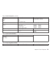
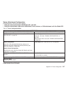
MAP 0121: Parallel with Twinax or Coax Attachments, Models 001, 002, or
003
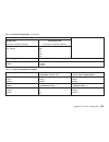
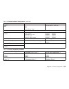
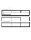
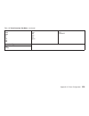
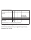
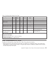
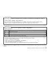
Table 5.
Symptom Explanation
Suspected FRUs/Causes
015 COMMUNICATIONS CHECK
017 COMMUNICATIONS CHECK
027 COMMUNICATIONS CHECK
028 COMMUNICATIONS CHECK
065 NO ATTACHMENT CARD, Models 001, 002
066 PRINTER BOARD FAILURE, Models 001, 002
200 ATTACHMENT INCOMPATIBLE, Model 003
203 ATTACHMENT CARD FAILURE, Model 003
Print Test OK, no print from host,
Incorrect or garbled print, wrong characters print
Printer configuration
Logic board (includes parallel attachment)
Host cable
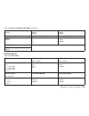
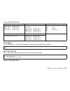
Models 001, 002:
coax or twinax attachment card
Model 003:
plug connection
Logic board (includes parallel attachment)
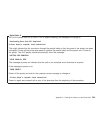
Note: Printing in hexadecimal code is available to aid service personnel and programmers for host program
debug. Press the Stop key, the Hex Print key, and the Start key. Printing will now be in hexadecimal code.
Refer to a 4247 User’s Guide for instructions.
Chapter 1. Diagnosing Problems
41
Summary of 4247
Page 1
4247 printers maintenance information document number: sa24-4400-05 part number: 27p8450 ibm.
Page 2
Note! Before using this information and the product it supports, read the information in “safety information” on page 9. Sixth edition (february 2001) this edition replaces sa24-4400-04. Requests for ibm ® publications should be made to your ibm representative or to the ibm branch office serving you...
Page 3: Contents
Contents safety information. . . . . . . . . . . . . . . . . . . . . . . . . . . . . . . . . . . . . . . . . . . . . . . . . 9 safety notices . . . . . . . . . . . . . . . . . . . . . . . . . . . . . . . . . . . . . . . . . . . . . . . . . . . 9 general safety . . . . . . . . . . . . . . . . . . . ....
Page 4
Map 0170: asf stacker . . . . . . . . . . . . . . . . . . . . . . . . . . . . . . . . . . . . . . . . . . . . . 94 map 0180: top cover interlock . . . . . . . . . . . . . . . . . . . . . . . . . . . . . . . . . . . . . . . . . . 98 map 0190: form feed problems . . . . . . . . . . . . . . . . . . . ....
Page 5
How to print the printer configuration and the custom sets . . . . . . . . . . . . . . . . . . . . . . . . . 198 how to print and clear the error log, and print the usage metrics . . . . . . . . . . . . . . . . . . . . . . 198 how to run the test and diagnostic (t&d) programs . . . . . . . . . . . ....
Page 6
Bidirectional printing . . . . . . . . . . . . . . . . . . . . . . . . . . . . . . . . . . . . . . . . . . . . . . 294 tear-off line . . . . . . . . . . . . . . . . . . . . . . . . . . . . . . . . . . . . . . . . . . . . . . . . . . 295 sensor service checks . . . . . . . . . . . . . . . . . . . . ....
Page 7
Platen pinch roller assembly . . . . . . . . . . . . . . . . . . . . . . . . . . . . . . . . . . . . . . . . . 411 carriage drive motor assembly . . . . . . . . . . . . . . . . . . . . . . . . . . . . . . . . . . . . . . . . 415 carriage drive belt. . . . . . . . . . . . . . . . . . . . . . . . . . ...
Page 8
Appendix a. Printer configuration. . . . . . . . . . . . . . . . . . . . . . . . . . . . . . . . . . . . . . . 484 configuration information — all models . . . . . . . . . . . . . . . . . . . . . . . . . . . . . . . . . . . . . 484 overview . . . . . . . . . . . . . . . . . . . . . . . . . . . . . ....
Page 9: Safety Information
Safety information this section contains information that you need to be familiar with before servicing this printer. Safety notices there are two levels of safety notices that appear in this maintenance information. V danger calls attention to a situation that is potentially lethal or extremely haz...
Page 10
Danger primary power is present on the power supply when the power cable is connected, even when the power switch is set to o (off). Danger do not connect or disconnect any communication port, teleport, attachment connector, or power cord during an electrical storm. Caution: the printhead may be hot...
Page 11: General Safety
Caution: the ribbon motor may be hot. Wait for it to cool down. Caution: the carriage motor may be hot. Wait for it to cool down. Caution: the paper feed motor may be hot. Wait for it to cool down. General safety follow these rules to ensure general safety: v upon arrival at the job site, notice the...
Page 12
4. Lift by standing or by pushing up with your leg muscles; this action removes the strain from the muscles in your back. Do not attempt to lift any objects that weight more than 18 kg (39.7 lb) or objects that you think are too heavy for you . V do not perform any action that causes hazards to the ...
Page 13: Electrical Safety
Electrical safety for a detailed description of electrical safety, refer to electrical safety for ibm customer engineers , s229–8124. Observe the following rules when working on electrical equipment: v find the room emergency power-off (epo) switch, disconnecting switch, or electrical outlet. If an ...
Page 14
Remember: there must be a complete circuit to cause electrical shock. By observing the above rule, you may prevent a current from passing through your body. – when using testers, set the controls correctly and use the approved probe leads and accessories for that tester. Danger many customers have, ...
Page 15: Pre-Service Inspection
V if an electrical accident occurs: – use caution; do not become a victim yourself. – power off (o) the printer. – send another person to get medical aid. Pre-service inspection the intent of this inspection guide is to assist you in identifying potentially unsafe conditions on these products. Each ...
Page 16
B. A second star washer must be between frame ground and the wire lug. C. The power cord should be the appropriate type, shipped for the 4247 printer. D. Insulation must not be frayed nor worn. 6. Remove the covers. See “printer covers” on page 347. 7. Check that the power supply cover has not been ...
Page 17: Related Publications
Related publications model a00 publications the following publications provide information on the model a00: v ibm 4247 printer model a00 user’s guide , sa24-4404. This guide describes the operating procedures and contains information on printer setup, operation, maintenance, and error recovery and ...
Page 18: Model 003 Publications
V ibm 4247 printer models 001, 002 with coaxial attachment quick reference guide , sa24-4409. This guide shows the key functions of the models 001 and 002 and the available configuration values and the process for setting them. This reference is shipped with models 001 and 002 of the printer. Most o...
Page 19
Preface - what’s new in the model 003 this maintenance information manual is a comprehensive reference for the ibm 4247 printer, models a00, 001, 002, and the new 003. The model 003 is very similar in function to its predecessors, particularly the model 001, but it is different in several important ...
Page 20: Defining The Problem
Chapter 1. Diagnosing problems maintenance analysis procedures (maps) defining the problem these maintenance analysis procedures (maps) are designed to aid in diagnosing printer problems. The maps use a sequential plan for isolating the possible causes of printer problems and point you to the part n...
Page 21
V follow the sequence! Always do one question at a time. When a procedure precedes the question, do all of the steps in the procedure before answering the question. Some steps have additional information that pertains to that step. This information is in the map flow and is an aid in describing why ...
Page 22
Nvram non-volatile random access memory ovfl overflow sw err software error t & d test and diagnostic ipds ™ intelligent printer data stream ™ scs sna (systems network architecture) character string fru field replaceable unit otb one time burn modules esd electrostatic discharge nps network printer ...
Page 23: Map 0100: Start Of Call
Map 0100: start of call intermittent strategy for intermittent symptoms, see ″ map 0210: intermittent failures ″ on page 130. Note: 1. Maps will not diagnose mechanical noise problems. This type of problem should be solved by identifying the cause of the noise and then repairing or installing new pa...
Page 24
Table 1. Map 0100: start of call (continued) step questions/actions yes no 3. Is this a model a00? Model a00 messages - locate the model a00 message in “reference table 1, model a00 error messages” on page 133 and perform the recommended action. Note: this table does not list all the messages that m...
Page 25
Table 1. Map 0100: start of call (continued) step questions/actions yes no 5. Is the problem print quality? Find the description of the failure in “reference table 4, print quality failures” on page 146, and perform the action suggested. Find the description of the failure in “reference table 5, ope...
Page 26
Map 0110: automatic sheet feeder symptom explanation suspected frus/causes 02 forms jam 099 forms jammed automatic sheet feeder (asf) failures paper or debris in forms path mechanical main paper feed printer logic board cable stacker bins before starting this map: 1. Ensure that the asf cable is plu...
Page 27
V the paper load lever is located on the right side of each bin when viewed from the rear of the printer. See figure 1. V the paper load lever is closed when it is pushed as far toward the front of the printer as possible. 5. Ensure that the paper guide on each side of each bin is correctly adjusted...
Page 28
Table 2. Map 0110: automatic sheet feeder step questions/actions yes no 1. Are you here due to a ’02’, or ’099’ display message? Go to step 2. Go to step 3 on page 30. Chapter 1. Diagnosing problems 28.
Page 29
Table 2. Map 0110: automatic sheet feeder (continued) step questions/actions yes no 2. Check for paper or debris in the path. Do forms feed into the stacker without jamming? The ’02’ or ’099’ display message is false. A. Run t&d11 to tune the sensors. For model a00, see “test and diagnostic informat...
Page 30
Table 2. Map 0110: automatic sheet feeder (continued) step questions/actions yes no 3. Are you here because bin 2 or bin 3 failed to feed paper? Go to step 4. Go to step 5. 4. A. Swap the bad bin connector with the bin 1 connector. See figure 75 on page 322. B. From the operator panel, load paper fr...
Page 31
Table 2. Map 0110: automatic sheet feeder (continued) step questions/actions yes no 8. Do you have the stacker/asf loop-back connector (pn 08h7271)? Go to step 9. Install a new logic board. For model 003, see “logic board - model 003” on page 366. For model a00, see “logic board - model a00” on page...
Page 32
Table 2. Map 0110: automatic sheet feeder (continued) step questions/actions yes no 9. Run t&d10 in single test mode to test the stacker/asf. For model a00, see “how to run the test and diagnostic (t&d) programs” on page 161. For models 001, 002, or 003, see “how to run the test and diagnostic (t&d)...
Page 33
Map 0120: parallel or serial attachment, model a00 and model 003 symptom explanation suspected frus/causes communication failures 020 dsr error 220 serial dsr error power on configuration (model a00) serial attachment card logic board (includes parallel attachment) host cable parallel and serial con...
Page 34
Model 003 with serial card v when the model 003 has a serial card installed, it displays parallel attachment on the operator’s panel. V when one cycles through the options found by pressing the menu key, the configuration menu should appear: table 3. Configuration menu parallel and serial configurat...
Page 35
Danger to prevent serious personal injury from electrical shock when connecting or disconnecting the interface cable, set the printer power switch to o (off) and unplug the power cord. Danger do not connect or disconnect any communication port, teleport, attachment connector, or power cord during an...
Page 36
Table 4. Map 0120: attachment, model a00 step questions/actions yes no 1. The following items are listed with the most probable failing item first. Check the first list item and test the printer. If the printer still fails, continue with the next list item. A. Communications cable and connector pins...
Page 37
Table 4. Map 0120: attachment, model a00 (continued) step questions/actions yes no c. Ensure that cable length restrictions are not exceeded. Refer to the signal cable ordering information in the ibm 4247 printer model a00 user’s guide (sa24-4404) for attachment cable configurations. Is the problem ...
Page 38
Table 4. Map 0120: attachment, model a00 (continued) step questions/actions yes no 3. There are two serial loop-back connectors. One for rs-232c (pn 08h7268) and one for rs-422a (pn 08h7259). Do you have the serial loop-back connectors for this printer? Go to step 4 on page 39. Install a new serial ...
Page 39
Table 4. Map 0120: attachment, model a00 (continued) step questions/actions yes no 4. Install the rs-232c loop-back connector. Run t&d9 in single test mode to test the serial attachment circuits. See “how to run the test and diagnostic (t&d) programs” on page 161 for model a00. For model 003, see “h...
Page 40
Table 4. Map 0120: attachment, model a00 (continued) step questions/actions yes no 6. Do you have the parallel loop-back connector (pn 08h7269) for this printer? Go to step 7. Install a new logic board. See “logic board - model a00” on page 370. For model 003, see “logic board - model 003” on page 3...
Page 41: 003
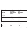
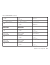
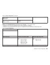
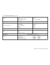
Map 0121: parallel with twinax or coax attachments, models 001, 002, or 003 table 5. Symptom explanation suspected frus/causes 015 communications check 017 communications check 027 communications check 028 communications check 065 no attachment card, models 001, 002 066 printer board failure, models...
Page 42
Danger to prevent serious personal injury from electrical shock when connecting or disconnecting the interface cable, set the printer power switch to o (off) and unplug the power cable. Danger do not connect or disconnect any communication port, teleport, attachment connector, or power cord during a...
Page 43
Table 6. Map 0121: attachment, models 001, 002, or 003 (continued) step questions/actions yes no 3. Are you here due to a ’065’ display message on model 001 or 002? Go to step 5 on page 44. Message ’066’ indicates that the attachment card did not establish communication with the printer main logic b...
Page 44
Table 6. Map 0121: attachment, models 001, 002, or 003 (continued) step questions/actions yes no 4. Are you here due to a ’200’ display message on model 003? The attachment card (twinax or coax) is incorrect for the base code. Install the other type of card. If this is a coax card, it must be instal...
Page 45
Table 6. Map 0121: attachment, models 001, 002, or 003 (continued) step questions/actions yes no 6. The following items are listed with the most probable failing item first. Check the first list item and test the printer. If the printer still fails, continue with the next list item. A. Check the hos...
Page 46
Table 6. Map 0121: attachment, models 001, 002, or 003 (continued) step questions/actions yes no 7. Is the failure with the parallel attachment? Go to step 6 on page 45. Go to step 10. 8. Do you have the parallel loop-back connector (pn 08h7269) for this printer? Go to step 7. Install a new logic bo...
Page 47
Table 6. Map 0121: attachment, models 001, 002, or 003 (continued) step questions/actions yes no 11. Models 001, 002: follow “attachment card procedure 1” on page 50, and return here. Do the attachment card feature resistors and s1 module match the host connection feature? Model 003: see “model 003 ...
Page 48
Table 6. Map 0121: attachment, models 001, 002, or 003 (continued) step questions/actions yes no 14. Models 001, 002: follow “attachment card procedure 2” on page 56, and return here. Do the logic board microcode modules match the host connect feature? Go to step 15. Repair as needed. Run t&d in aut...
Page 49
Table 6. Map 0121: attachment, models 001, 002, or 003 (continued) step questions/actions yes no 18. Are you here because of a t&d 30–38 failure, a ’015’, ’017’, ’027’, ’028’ error, or no print from host or wrong printed character. Replace the attachment card. See “model 003 attachment cards: serial...
Page 50
Attachment card procedure 1 models 001 and 002 connect to a host by using one of the following features: v coax ipds attachment v coax scs attachment v twinax ipds attachment v twinax scs attachment proper operation of the feature requires the correct combination of attachment card and microcode mod...
Page 51
Figure 2 and figure 3 on page 52 show you how to use the feature resistors to identify the attachment card (models 001, 002). Use the figure that matches your attachment card. To correctly view the resistors: level 1 (long) card: hold the attachment card with the cable toward you. - or - level 2 (sh...
Page 52
Figure 4 on page 53 shows the location and orientation of the attachment card microcode module (s1) on the level 1 (long) attachment card. Figure 5 on page 53 shows the location and orientation of the attachment card microcode module on the level 2 (short) attachment card. The position of the corner...
Page 53
Use figure 2 on page 51, figure 4, and figure 7 on page 55 to verify that the: v attachment card feature resistors and s1 module label match your host connection feature. V s1 module is installed in the correct orientation. The dotted line depicted on the s1 module in figure 3 on page 52 represents ...
Page 54
Attention: incorrect orientation of the module will damage the module and can damage the attachment card. Card to logic board cable microcode module s1 twinax connector coax connector corner cut off bevel bevel orientation marks 182 mm e90aloc8 7.2 in. Figure 6. Models 001 and 002, orientation marks...
Page 55
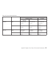
Return to step 11 on page 47. Feature name feature resistors module s1 label coax ipds (both levels) coax scs (level 1) twinax ipds (both levels) coax scs (level 2) (has metal shield) twinax scs (level 1) twinax scs (level 2) kxciavvv s01 crc kxcsavvv s01 crc kxcsavvv s01 crc kxtsavvv s01 crc kxtiav...
Page 56
Attachment card procedure 2 figure 8 shows the location and orientation of the model 001 (early-level) and the model 002 logic board controller microcode module u54. Figure 9 shows the location and orientation of the model 001 (early-level) and model 002 logic board generator microcode module, u2. F...
Page 57
Figure 10 shows the location and orientation of the model 001 (late-level) logic board generator microcode modules, u54 and u2. Use figure 8 on page 56, figure 9 on page 56, figure 10, and figure 11 on page 58 to verify that the information on the u54 and u2 module labels matches your host connectio...
Page 58
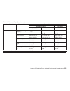
K2 (x=2) is the module designation for model 001. K5 (x=5) is the module designation for model 002. The vvv is a 3 digit number that indicates the module code version number. Return to step 14 on page 48. Feature name module u54 label module u2 label coax ipds coax scs twinax ipds twinax scs kxcxcvv...
Page 59
Map 0122: network print server attachment symptom explanation suspected frus/causes network print server (nps) communication failures host and print server configuration network print server logic board (includes parallel attachment) lan cable note: for nps 540+ (part number 30h4054) units attached ...
Page 60
Danger to prevent serious personal injury from electrical shock when connecting or disconnecting the interface cable, set the printer power switch to o (off) and unplug the power cable. Danger do not connect or disconnect any communication port, teleport, attachment connector, or power cord during a...
Page 61
Table 7. Map 0122: network print server attachment (continued) step questions/actions yes no 2. Tests with the communication line connected work with each symptom in “reference table 7, network server problems – nps and lan attachment card” on page 156 before going to the next item. Is the problem c...
Page 62
Map 0130: no paper movement symptom explanation suspected frus/causes paper load and feed failures no paper movement 099 condition persists paper feed motor printer logic board mechanical parts table 8. Map 0130: no paper movement step questions/actions yes no 1. Perform the main paper drive service...
Page 63
Table 8. Map 0130: no paper movement (continued) step questions/actions yes no 2. A. Use t&d11 to determine if the paper feed motor pulley turns. Sensor tuning uses the paper feed motor to engage and disengage the platen pinch rollers. B. Remove the front tractor assembly (if installed). C. Run t&d1...
Page 64
Table 8. Map 0130: no paper movement (continued) step questions/actions yes no 3. Perform the tractor assembly service check. Go to “tractor assembly service check” on page 325 is the service check ok? Install a new tractor assembly in the failing position (front or rear). - or - install a new logic...
Page 65
Table 8. Map 0130: no paper movement (continued) step questions/actions yes no 4. Disconnect the paper feed motor connector from the logic board. See “paper feed motor wiring” on page 248 to measure the resistance of the motor windings. Is the measurement correct for both windings? Install a new log...
Page 66
Map 0131: paper path sensor symptom explanation suspected frus/causes 01 end of forms 001 end of forms 11 load bin 1, 2, or 3 011 check/load bin 1, 2, or 3 031 end of forms timeout paper sensor failure logic board sensor cable assembly table 9. Map 0131: paper path sensor step questions/actions yes ...
Page 67
Table 9. Map 0131: paper path sensor (continued) step questions/actions yes no 4. A. Remove the forms. B. Run t&d11 to tune the sensors. For model a00, see “how to run the test and diagnostic (t&d) programs” on page 161. For models 001, 002, or 003, see “how to run the test and diagnostic (t&d) prog...
Page 68
Table 9. Map 0131: paper path sensor (continued) step questions/actions yes no 5. Is the current forms path either rear pull or push-pull? Run t&d21 and verify correct sensor operation. If not ok: v install a new logic board. For model a00, see “logic board - model a00” on page 370. For models 001 a...
Page 69
Table 9. Map 0131: paper path sensor (continued) step questions/actions yes no 6. Open the top cover. Is paper visible between the printhead and the platen? Run t&d21 and verify correct sensor operation. If not ok: v install a new logic board. For model a00, see “logic board - model a00” on page 370...
Page 70: Map 0140: Printhead Drive
Map 0140: printhead drive symptom explanation suspected frus/causes 56 print error 73 sw err 4 3 x 053 machine check err 3 x x 053 machine check err 4 3 x 056 machine check carriage slams into sides printing slows or stops ribbon defective or incorrectly installed ragged tear-offs on continuous form...
Page 71
Table 10. Map 0140: printhead drive step questions/actions yes no 1. The ribbon lift bar, lift bracket, and ribbon guide are part of the ribbon assembly. These parts can cause printhead drive problems remove the ribbon (see “ribbon” on page 353). Print a print test. If this is a model a00, see “how ...
Page 72
Table 10. Map 0140: printhead drive (continued) step questions/actions yes no 3. Power off (o) the printer. Perform the printhead drive service check. See “printhead drive service check” on page 333. Is the service check ok? Go to step 4. Repair as needed. Run t&d in automatic mode to verify correct...
Page 73
Table 10. Map 0140: printhead drive (continued) step questions/actions yes no 6. An open printhead thermal sensor can cause the printhead drive to stop. Remove the printhead. See “printhead” on page 356. For model a00, 001 and 003, see “18-wire printhead wiring (models a00, 001, and 003)” on page 24...
Page 74
Table 10. Map 0140: printhead drive (continued) step questions/actions yes no 7. Disconnect the 26-conductor printhead cable from the logic board (see “chapter 4. Locations” on page 265). See “printhead cable wiring” on page 258 to measure the resistance of pin 5 end-to-end and pin 6 end-to-end (the...
Page 75: Map 0150: Power Supply
Map 0150: power supply models a00, 001, and 002, use a low voltage or high voltage power supply depending on the country in which the printer is found. The model 003 has a auto-ranging universal power supply. Warning: do not install a power supply with a different part number. Symptom explanation su...
Page 76
Danger primary power is present on the power supply when the power cable is connected, even when the power switch is set to o (off). Table 11. Map 0150: power supply questions/actions yes no 1. Power off (o) the printer. Unplug the power cord from the voltage source. Verify that the power source vol...
Page 77
Table 11. Map 0150: power supply (continued) questions/actions yes no 3. Put the covers in the service position. See “removing covers” on page 275. Disconnect the power supply fan from the power supply board. Power supply pins and connectors: disconnect the carriage motor fan from the power supply b...
Page 80
Table 11. Map 0150: power supply (continued) questions/actions yes no 7. A. Power off (o) the printer. B. Remove the attachment card. V for model a00, see “serial attachment card - model a00” on page 390. V for models 001, and 002, see “coax attachment card - models 001, and 002” on page 392. Or, fo...
Page 86
Table 11. Map 0150: power supply (continued) questions/actions yes no 17. A. Power off (o) the printer. B. Install the attachment card. V for model a00, see “serial attachment card - model a00” on page 390. V for models 001, and 002, see “coax attachment card - models 001, and 002” on page 392. Or, ...
Page 89
Map 0160: ribbon feed and ribbon lift symptom explanation suspected frus/causes 73 sw err 4 0 x 89 ribbon jam 053 machine check err 4 0 x 089 ribbon jam ribbon feed or lift failures ribbon installation (refer to a 4247 user’s guide) ribbon cartridge (customer responsibility) ribbon drive motor ribbo...
Page 90
Table 12. Map 0160: ribbon feed and ribbon lift (continued) step questions/actions yes no 3. Does the ribbon motor run continuously? Install a new logic board. For model a00, see “logic board - model a00” on page 370. For models 001 and 002, see “logic board - models 001 and 002” on page 378. Or “lo...
Page 91
Table 12. Map 0160: ribbon feed and ribbon lift (continued) step questions/actions yes no 6. Did the ribbon lift ok? Return to the step that sent you to this map. Go to step 8 on page 92. 7. Power off (o) the printer. Disconnect the ribbon motor connector at the logic board. See “ribbon drive motor ...
Page 92
Table 12. Map 0160: ribbon feed and ribbon lift (continued) step questions/actions yes no 8. Power off (o) the printer. Disconnect the ribbon lift motor connector at the printhead (see figure 106 on page 357). Measure the resistance of the motor windings. See “ribbon lift motor wiring” on page 253. ...
Page 93
Table 12. Map 0160: ribbon feed and ribbon lift (continued) step questions/actions yes no 9. Remove the printhead. See “printhead” on page 356. Measure the resistance between the connector pins on the printhead; in “reference table 10, ribbon lift and 26–pin cable connectors” on page 158. Is the res...
Page 94: Map 0170: Asf Stacker
Map 0170: asf stacker symptom explanation suspected frus/causes 02 forms jam 97 stacker error 087 stacker error 099 forms jammed stacker failures mechanical parts printer logic board asf stacker assembly asf stacker cable assembly table 13. Map 0170: asf stacker step questions/actions yes no 1. Are ...
Page 95
Table 13. Map 0170: asf stacker (continued) step questions/actions yes no 3. The stacker has a motor that transfers the stacker vane. When asf or manual sheet feed configurations are used, the stacker vane will be in the down position to guide the paper into the stacker. When fanfold push configurat...
Page 96
Table 13. Map 0170: asf stacker (continued) step questions/actions yes no 4. Perform the main paper drive service check. See “main paper drive check and adjustment” on page 301. Is the main paper drive service check ok? Go to step 5. Repair as needed. 5. Perform the stacker service check. See “asf s...
Page 97
Table 13. Map 0170: asf stacker (continued) step questions/actions yes no 7. 1. Remove the stacker assembly. 2. Install the stacker/asf loop-back connector in the stacker connector. 3. Run t&d10 in single test mode to test the stacker circuits. For model a00, see “how to run the test and diagnostic ...
Page 98
Map 0180: top cover interlock symptom explanation suspected frus/causes 96 cover open 90 close cover 096 not ready cover open t&d19 top cover interlock test failure top cover top cover magnet operator panel printer logic board operator panel cable asf stacker assembly asf stacker assembly cable tabl...
Page 99
Table 14. Map 0180: top cover interlock (continued) step questions/actions yes no 2. Inspect the following parts for wear, damage, or binds: v top cover v top cover magnet (located near the right end of the stacker assembly when the cover is closed) note: when the asf/stacker top cover is installed,...
Page 100
Table 14. Map 0180: top cover interlock (continued) step questions/actions yes no 3. Inspect the following parts for wear, damage, or binds: v top cover magnet (located near the left side of the operator panel, when the cover is closed) v operator panel cable and connectors are the parts ok? Install...
Page 101
Map 0190: form feed problems symptom explanation suspected frus/causes 02 forms jam 002 forms jammed front tractor 020 forms jammed rear tractor 088 invalid paper source 099 forms jammed forms jam forms stick together debris or unwanted paper in forms path tractor assembly mechanical parts logic boa...
Page 102
Table 15. Map 0190: forms feed problems step questions/actions yes no 1. Forms feed problems can have multiple causes. While following this map, do not stop your search after resolving the first cause. This is especially true when you are investigating environmental and usage problems. Search for ad...
Page 103
Table 15. Map 0190: forms feed problems (continued) step questions/actions yes no 2. Examine the tractors for jammed or damaged forms. Are the forms ok? Go to step 3. Remove any jammed or damaged forms. You should investigate further to find the root cause of the jamming. Go to step 6 on page 106. 3...
Page 104
Table 15. Map 0190: forms feed problems (continued) step questions/actions yes no 4. Check for worn tractor jam sensors. Examine the plastic surfaces of the sensor for signs of wear. Are the sensor surfaces ok? Go to step 5 on page 105. Replace the tractor assembly. Run t&d in automatic test mode to...
Page 105
Table 15. Map 0190: forms feed problems (continued) step questions/actions yes no 5. Look closely at the tractor sensor in dim light. There is a small red led visible in the sensor surface, over which the forms pass. You may need to cup your hand around the sensor to be able to see the led. This led...
Page 106
Table 15. Map 0190: forms feed problems (continued) step questions/actions yes no 6. Check for damage to the inner forms guide surface or to the hinges on the inner forms guide. Is the inner forms guide ok? Go to step 7 on page 107. Repair, as needed. Run t&d in automatic mode to verify correct prin...
Page 107
Table 15. Map 0190: forms feed problems (continued) step questions/actions yes no 7. An incorrect metal forms guide deflector position or an incorrect paper bail position can cause forms feed failures. The metal forms guide deflector is closed in the up position and open when it is in the down posit...
Page 108
Table 15. Map 0190: forms feed problems (continued) step questions/actions yes no 8. Continued from step 7 on page 107. The paper bail is removed from the printer when the rear pull forms path is used. When the paper bail is installed, ensure that it is installed as shown. Hc0z0002 are the paper bai...
Page 109
Table 15. Map 0190: forms feed problems (continued) step questions/actions yes no 11. Is the rear cabinet asf cover installed on the printer. Go to step 12 on page 110. Install the rear cabinet asf cover. If it is missing, the forms for the rear push path are often loaded incorrectly. Continue with ...
Page 110
Table 15. Map 0190: forms feed problems (continued) step questions/actions yes no 12. Check that the rear tractor is installed correctly, and the rear tractor paper door is open or removed. The following figure shows the positions of the rear tractor for pull mode and push mode. See step 16 on page ...
Page 111
Table 15. Map 0190: forms feed problems (continued) step questions/actions yes no 14. Check that the bellcrank is correctly moving the lower pinch rollers up and down. Check the parts at the left end of the platen. The bellcrank must be positioned between the gear and the washer. See step 33 on page...
Page 112
Table 15. Map 0190: forms feed problems (continued) step questions/actions yes no 16. Power off (o) the printer. If the rear paper door does not stay open, remove the door from the printer. Remove the rear tractor from the printer. To configure the tractor for rear push mode: v place the tractor fac...
Page 113
Table 15. Map 0190: forms feed problems (continued) step questions/actions yes no 18. Make the following checks: a. Forms input and output stacking follows the recommendations in “forms stacking recommendations” on page 539. B. Input forms are aligned to feed straight into the printer. C. Input form...
Page 114
Table 15. Map 0190: forms feed problems (continued) step questions/actions yes no 19. Make the following checks: v inspect the condition of the paper bail plastic shield and lower plastic shield. Ensure that the shields are firmly attached. Note: if you suspect lower plastic shield damage, determine...
Page 115
Table 15. Map 0190: forms feed problems (continued) step questions/actions yes no 20. Make the following checks of the printhead mask: v locate and remove debris or adhesive from the printhead mask opening. V check the printhead mask for damage or incorrect installation. Adhesive mask carriage (plat...
Page 116
Table 15. Map 0190: forms feed problems (continued) step questions/actions yes no 23. Do the forms jam after they leave the tractor assembly? Go to step 24. Go to “tractor assembly service check” on page 325. 24. Perform the main paper drive service check and the paper path service check indicated b...
Page 117
Table 15. Map 0190: forms feed problems (continued) step questions/actions yes no 25. A paper presence sensor failure can cause a ’02’ or ’099’ forms jam message to display instead of a ’01’, ’11’, ’001’, or ’011’ end of forms message. Did the printer fail to detect end of forms? Run t&d21, includin...
Page 118
Table 15. Map 0190: forms feed problems (continued) step questions/actions yes no 26. A paper presence sensor failure can cause a ’02’ or ’099’ forms jam message to display after a park or eject operation. Did a park or eject operation cause the error message? Run t&d21, including performing a senso...
Page 119
Table 15. Map 0190: forms feed problems (continued) step questions/actions yes no 27. Perform the tractor assembly service check. Go to “tractor assembly service check” on page 325. Is the service check ok? Install a new tractor assembly in the failing position (front or rear). If the printer is sti...
Page 120
Table 15. Map 0190: forms feed problems (continued) step questions/actions yes no 28. This is a 099 message or the a00 equivalent. Check for customer operating errors. Was the customer performing a park operation? Tear off the forms in the area between the printhead and the tear bar. Complete the pa...
Page 121
Table 15. Map 0190: forms feed problems (continued) step questions/actions yes no 31. Examine the sensors and the area around the sensors for pieces of paper or chad, which the printer will sense as forms. On model a00, the flashing path light on the operator panel is an indication of which path det...
Page 122
Table 15. Map 0190: forms feed problems (continued) step questions/actions yes no 33. Check that the bellcrank is correctly moving the lower pinch rollers up and down. Check the parts at the left end of the platen. The bellcrank must be positioned between the platen gear and the washer. E90aas4 wash...
Page 123
Table 15. Map 0190: forms feed problems (continued) step questions/actions yes no 34. As a platen becomes worn from use, the surface can become shiny and more reflective. This shine can be interpreted by the sensors as paper present on the platen. Check the platen for a shiny surface and for cuts an...
Page 124
Table 15. Map 0190: forms feed problems (continued) step questions/actions yes no 35. Check the sensor cable assembly for wear or damage. Is it ok? Install a new logic board. Run t&d in automatic test mode to verify correct printer operation. For model a00, see “how to run the test and diagnostic (t...
Page 125
Table 15. Map 0190: forms feed problems (continued) step questions/actions yes no 36. Run t&d 14 to determine the microcode levels in the printer. The controller code must be at least at the levels indicated in “reference table 12, minimum microcode” on page 158, to have the latest sensor threshold ...
Page 126
Table 15. Map 0190: forms feed problems (continued) step questions/actions yes no 38. Replace the upper feed roller. Replace the platen. Verify that the bail assembly has 2 blue dots on the right side. Replace it if it does not. Run t&d 11 to reset the sensor thresholds. Is the problem resolved? You...
Page 127: Map 0200: 55 Afta Errors
Map 0200: 55 afta errors symptom explanation suspected frus/causes 55 afta error 055 machine check the afta sensor circuit did not detect that needle 5 (model 002) or 5b (models a00, 001, 003) moved at the correct time during the afta routine. The needle either failed to extend or was not detected w...
Page 128
Table 16. Map 0200: 55 afta errors step questions/actions yes no 1. Perform the standard afta service check, see “standard afta service check and adjustment” on page 285. Is the service check ok? Go to step 2 on page 129. Repair as needed. Mount forms, and try loading and parking forms several times...
Page 129
Table 16. Map 0200: 55 afta errors (continued) step questions/actions yes no 2. Check the printhead cables. A. Remove the printhead. See “printhead” on page 356. B. Inspect the printhead flat cables for damage. C. If the printer is a model a00, 001 or 003 (18-needle printhead): v disconnect the 22-c...
Page 130
Map 0210: intermittent failures symptom explanation suspected frus/causes intermittent failures loose connectors esd grounds damaged wires general information all possible indications and symptoms should be recorded to aid you in using this map. System error logs, when available, aid in identifying ...
Page 131
Intermittent problems may be caused by out of range voltages. Check the voltages by following the procedures in “map 0150: power supply” on page 75. Electrostatic discharge (esd) intermittent problems can also be caused by build up of electrostatic charge on the forms or bad electrostatic ground (es...
Page 132
Environmental requirements see “operating environment” on page 546. Miscellaneous check for lost screws under the power supply or under the logic board. Chapter 1. Diagnosing problems 132.
Page 133: Maps Reference Tables
Maps reference tables reference table 1, model a00 error messages table 17. Model a00 error messages message description action 01 end of forms forms do not load when load/form feed key is pressed. No forms movement. See “map 0130: no paper movement” on page 62. 01 end of forms forms are visible bet...
Page 134
Table 17. Model a00 error messages (continued) message description action 21 ovfl error check intf host attachment buffer overflow error on the serial interface. 1. Press online to clear the display message. 2. In power on configuration, increase the buffer size and or change the pacing protocol xon...
Page 135
Table 17. Model a00 error messages (continued) message description action 73 sw err 3xx firmware error detected during initialization of printhead drive. Power off and power on the printer. If message remains, see “map 0140: printhead drive” on page 70. 73 sw err 40x firmware error detected during i...
Page 136
Table 17. Model a00 error messages (continued) message description action jumper and keys manufacturing use only. 1. Remove the jumper from the bottom of the operator panel. 2. Install a new emi filter assembly (used only with early-level logic boards). See “emi filter (model a00 early-level logic b...
Page 137
Table 18. Error messages for models 001, 002, and 003 (continued) message description action 007 incorrect print order press stop then start (coax interface only) invalid order received from host. Press stop, then start. 008 hold print timeout press stop then start (coax interface only) start key no...
Page 138
Table 18. Error messages for models 001, 002, and 003 (continued) message description action 020 forms jammed rear tractor clear jam and reload forms jam detected at the rear tractor sensor. See “map 0190: form feed problems” on page 101. 022 unit address not received check printer address (twinax i...
Page 139
Table 18. Error messages for models 001, 002, and 003 (continued) message description action 032 forms jammed timeout clear jam and reload forms (coax interface only) 002 forms jammed front tractor or 020 forms jammed rear tractor condition exceeded 60 seconds. Jam detected at the front or rear trac...
Page 140
Table 18. Error messages for models 001, 002, and 003 (continued) message description action 050 machine check err xxx firmware error in supervisor code. Power off and power on the printer. If message remains, install a new logic board. See “logic board - models 001 and 002” on page 378. Or “logic b...
Page 141
Table 18. Error messages for models 001, 002, and 003 (continued) message description action 053 machine check err 41x 053 machine check err 43x firmware error detected during initialization of printhead home sensor. Power off and power on the printer. If message remains: 1. Ensure no paper or debri...
Page 142
Table 18. Error messages for models 001, 002, and 003 (continued) message description action 070 printer board changed verify configuration settings occurs when printer logic board or microcode version has been replaced. Verify printer configuration settings and custom sets. 087 stacker error instal...
Page 143
Table 18. Error messages for models 001, 002, and 003 (continued) message description action 098 hold print timeout press load (coax interface only) 003 forms ejected condition exceeded 60 seconds. Press load. 099 forms jammed clear jam then press start (asf paper path) paper still present after att...
Page 144
Table 18. Error messages for models 001, 002, and 003 (continued) message description action 201 no attachment card found model 003 twinax code see user’s guide a serial, lan, or twinax attachment card was not found during the current power on, but was previously. 1. If attachment card was removed, ...
Page 145
Table 18. Error messages for models 001, 002, and 003 (continued) message description action 220 serial dsr error model 003 twinax code see user’s guide a remote connection serial interface error condition was detected. The data set ready or data carrier detect signal was not sensed. See “map 0120: ...
Page 146
Reference table 3, no printed characters failure: no printed characters appear action no print from any source (host or print test). If there is no carriage motion: v see “map 0140: printhead drive” on page 70. V see “map 0150: power supply” on page 75. If there is carriage motion: 1. Check that the...
Page 147
Print quality failures (darkness, location, quality) action character or line spacing uneven or overprinting. 1. See “main paper drive check and adjustment” on page 301 and check the separate path in use. See “individual forms paths checks” on page 310. 2. See “printhead drive service check” on page...
Page 148
Print quality failures (darkness, location, quality) action vertical print line misalignment (lines move upward, page-to-page). 1. Install a new upper feed roller. 2. Install the latest level paper bail assembly with the improved spring arrangement. The latest level paper bail has 2 blue tabs on the...
Page 149
Reference table 5, operator panel and miscellaneous problems description of failure action models 001, 002 or 003 - when menu is pressed, the operator panel displays recall custom set values. You cannot get other configuration menu selections to display. This is normal operation with controller code...
Page 150
Description of failure action buzzer sounds continuously. Install a new logic board. For model a00, see page “logic board - model a00” on page 370. For models 001 and 002, see page “logic board - models 001 and 002” on page 378. Or “logic board - model 003” on page 366. Install a new operator panel....
Page 151
Description of failure action ribbon life failures. See “map 0160: ribbon feed and ribbon lift” on page 89. Ribbon feed or lift failure. See “map 0160: ribbon feed and ribbon lift” on page 89. Loud noise during sensor tuning. Run t&d11 (pinch roller status). For model a00, see “how to run the test a...
Page 152: Attachment Card
Description of failure action asf stacker failure. See “map 0170: asf stacker” on page 94. Fanfold paper enters the asf stacker assembly. See “map 0170: asf stacker” on page 94. Paper from the asf or manual sheet feed tray fails to enter the asf stacker. See “map 0170: asf stacker” on page 94. Refer...
Page 153
Symptom probable cause action network or packet light continues to flash after power on internal error occurred for external nps (all models): 1. Disconnect the power cable at the nps unit. 2. Wait 10 seconds, then reconnect the power cable. 3. If the problem continues, replace the nps unit. For lan...
Page 154
Symptom probable cause action test page prints with error messages internal errors 1. Nvram e1 or nvram e2: a. Disconnect the power cable at the unit. B. Wait 10 seconds and reconnect. C. If the problem continues, replace the nps unit or lan card. 2. Nvram e3: a. Replace the nps unit or lan card. 3....
Page 155
Table 20. Reference table; nps 540+ with external power supply 1. Ensure the power supply is +9 volts. Caution: a +12 volt power supply will damage the nps. 2. Disconnect power supply from nps and check for +9 v ac output at the disconnected power supply. 3. If +9 v ac is missing, replace the power ...
Page 156: Card
Reference table 7, network server problems – nps and lan attachment card symptom probable cause action network light flashes rapidly after power on self test on external token ring nps (all models) incorrect ring speed selected select correct token ring speed. Power off the nps unit and try again. N...
Page 157
Table 22. Voltages (continued) pin voltage range pin 7 ground pin 8 ground pin 9 ground pin 10 ground pin 11 +38 v dc +36.5 / +39.5 v dc pin 12 +38 v dc +36.5 / +39.5 v dc pin 13 +38 v dc +36.5 / +39.5 v dc pin 14 n/a pin 15 see note notes: 1. Pin 15 is the idle control input signal from the logic b...
Page 158
Reference table 10, ribbon lift and 26–pin cable connectors table 24. Connectors ribbon lift connector 26-pin connector pin 1 pin 25 pin 2 pin 23 pin 3 pin 24 pin 4 pin 26 see “wiring diagrams” on page 240 for details on the location of the pins on the connector. Reference table 11, paper paths tabl...
Page 159
Table 26. Minimum microcode levels (continued) a00 2.09 1.16 001 coax 3.19 twinax 3.18 2.02 2.02 3.04 3.02 002 coax 2.19 twinax 2.18 2.03 2.03 3.03 3.02 003 5.05 5.05 5.05 chapter 1. Diagnosing problems 159.
Page 160: Chapter 2. Diagnostics
Chapter 2. Diagnostics test and diagnostic information - model a00 how to print the print test 1. Load forms. 2. Power off (o) the printer. 3. Press and hold the online key while powering on the printer. 4. Press and hold the online key until the printer has stopped all motion (approximately 20 seco...
Page 163
D. If an error is detected, an error message will display. Td xx fru x (x) e. For a description of error messages, go to “t&d error messages and actions” on page 190. F. Press the load/form feed key to end the t&d program. G. The following message will display: end t&d h. Power off (o) the printer a...
Page 164: T&d Descriptions
T&d descriptions 1. If an error message is displayed during the t&d program, note the error information. Td xx fru x (x) 2. Press any of the keys. 3. The following message will display: rept skip init 4. To repeat the last test, press the micro ↑ key to select rept. 5. To skip to the next test, pres...
Page 165
T&d03 - not used press the micro ↓ key to bypass this message. T&d04 - microcode test display: t&d 04 crc font * note: the asterisk will flash during the test. If an error message is displayed, go to “t&d error messages and actions” on page 190. The test completed successfully if the display advance...
Page 166
If a key is not pressed in approximately 10 seconds, an error message will display. If a timeout error message occurs, press the micro ↑ key twice to repeat t&d05 6. Continue to press the keys as each request is displayed. 7. If an error message is displayed, go to “t&d error messages and actions” o...
Page 167
T&d08 - microcode test display: t&d 08 user if an error message is displayed, go to “t&d error messages and actions” on page 190. The test completed successfully if the display advances to the next test number. T&d09 - serial attachment test the serial loop-back connector needs to be installed for t...
Page 168
If the loop-back connector is not installed, an error message will be displayed. To bypass this message, press the micro ↓ key twice to advance to the next test. Display: t&d fru 0[01] if an error message is displayed, go to “t&d error messages and actions” on page 190. The test completed successful...
Page 169
Important in the next step, ensure you do not power off the printer when removing the left side cover to look at the platen pinch-roller gear. 3. Remove the left side-cover and look at the platen pinch roller gear on the left side to determine if the rollers are closed (touching platen) or open (not...
Page 170
Gear display action open pinch open press the load/form feed key closed pinch open press the micro ↑ key open pinch close press the micro ↑ key 6. The next part of this procedure is forms path sensor tuning. The rear forms path sensor is mounted on one of the platen pinch roller assemblies. Because ...
Page 171
11. The test completed successfully if the display advances to the next test number. 12. T&d12 determines the number of motor steps to move from “full open” gap to the “1-part paper=0.1mm” print gap position. Calibrate the printer to the minimum allowed: 1-part paper=0.1 mm. T&d12 - afta calibrate t...
Page 172
1. Adjust the print gap in 0.25 mm (0.001 in.) increments to achieve acceptable print darkness. 2. Initiate t&d12 (see “running t&d12” on page 173). 3. Use store=no. 4. Move the value to +x to increase the gap and -x to decrease the gap. This adjustment is described in “standard afta service check a...
Page 173
Running t&d12: v press the micro ↑ key to run the test. V press the micro ↓ key to skip the test. V press the load/form key to end the test. If t&d11 (sensor tuning) was not completed before beginning t&d12, the following message displays: pinch xxxxx where xxxxx=open or closed. If the previous mess...
Page 174
3. Park the paper. 4. Set the operator menu to fixed=1. 5. Load a single-sheet of paper into the print area. Note the wheel position. 6. The wheel position should be the same for afta=0 and fixed=1 within ±0.25. 7. The wheel should be pointing to 1 ±0.25. 8. Verify printer operation by printing t&d1...
Page 175
The print test will print, and the following message displays: t&d 14 user 2. When the print test is complete, the following message is displayed: tear & press key 3. Tear off the printout, and press any key. 4. For printout analysis, see “print quality checks” on page 338. 5. If an error message is...
Page 176
Note: f.Fr adj is first print-line front tractor adjustment front fanfold forms path - to select the test for the front fanfold first-line adjustment, press the micro ↑ key, then go to step 1. - or - rear fanfold forms path - to advance to the rear, fanfold first-line adjustment, press the load/form...
Page 177
If the first print-line adjustment is not correct, press the load/form feed key to view the next display: + f.Fr xxx - note: x can be any number between -128 to +127. 7. To move the first print-line closer to the top of the paper, press the load/form feed key. To move the first print-line down away ...
Page 178
18. Press any key to feed the paper back into the printer and the following message will display: yesno if the first print-line adjustment is correct, press the micro ↑ key to store the first print-line position. Continue with step 21. - or - if the first print-line adjustment is not correct, press ...
Page 179
Continue with the next step when the following message displays: load paper 1. Install fanfold paper on the tractor assembly, and press the load/form feed key. + vert x - 2. Six blocks of the hs will be printed with a number in the middle and a line of hs and is printed on one line. Next, the paper ...
Page 180
Note: x can be any number between -6 and +6. 7. If the i is closer to the left leg of the h, decrease the number. If the i is closer to the right leg of the h, increase the number. Press the micro ↑ key for a positive value. Press the load/form feed key for a negative value. The range is -6 to +6. E...
Page 181
2. To advance to the rear, fanfold first-line adjustment, press the load/form feed key. See step 11 on page 183 . Load paper 3. Install fanfold paper in the front tractor assembly. 4. Press the load/form feed key. 5. A row of xs will be printed on the first print-line. The paper will feed to the tea...
Page 182
If the tear-off needs to be adjusted, press the micro ↑ key to move the paper up, or press the load/form feed key to move the paper down. The range is -128 to +127. Each unit is approximately 0.2 mm. When the tear-off is correct, go to the next step. Form perforation line tear edge of cover e61a0900...
Page 183
8. Press the micro ↓ key to get the next display message: yesno 9. Press the micro ↑ key to store the front tear-off adjustment and get the next display message: yes t.Re adj? No note: t.Re is tear-off line rear tractor adjustment 10. To exit this test without adjusting the rear tear-off line, press...
Page 184
19. If an error message is displayed, go to “t&d error messages and actions” on page 190. 20. The test completed successfully if the display advances to the next test number. T&d18 - single sheet feed printout use this test to check manual sheet paper feed and line skew. If the test completes succes...
Page 185
T&d19 - top cover interlock test if the top cover is open when this test starts, the following messages will alternately display: cover is open .. Please close it 1. Close the top cover, if open. The following message will display: open cover 2. Open the top cover. If do not open the cover in approx...
Page 186
2. To select this mode press the micro ↑ key, and go to step 10 on page 189. 3. To select the next printing mode, press the load/form feed key. The following message will display: y nlq 9 bidi n 4. In this mode, the printhead will print nlq by using 9 wires and two passes per line in bidirectional m...
Page 187
3. The following displays: y path status n 4. Press the micro ↑ key to display sensor status. Press the load/form feed key to skip to step 5. The current path status displays: c:x f:x r:x p:yy where: v c: is status of the cutsheet sensor v f: is status of the front fanfold sensor v r: is status of t...
Page 188
Threshold values written in nvram display: cx1 fx2 rx3(x4) where: v x1 is the threshold for manual path v x2 is the threshold for front path v x3 is the threshold for rear path and rollers closed v x4 is the threshold for rear path and rollers open v x1, x2, x3, x4 are numbers in hexadecimal format ...
Page 189
V x1, x2, x3, are numbers in hexadecimal format corresponding to the measured voltages with resolution of 20 mv. The display is continuously updated to track sensor output changes. Press the micro ↑ key to go to step 9. 9. The following displays: y repeat test n press the micro ↑ key to restart from...
Page 190
T&d error messages and actions table 27 lists the messages that may occur while you are performing test and diagnostic procedures. Table 27. T&d error messages and action error message description action td 0 fru 0 1 microcode error replace the logic board. See “logic board - model a00” on page 370....
Page 191
Table 27. T&d error messages and action (continued) error message description action td 5 fru 1 x operator panel failure 1. This error can occur if a key is not pressed in less than 10 seconds. Run t&d05 again to verify the problem. 2. Replace the operator panel. See “operator panel” on page 355. 3....
Page 192
Table 27. T&d error messages and action (continued) error message description action td 12 fru 0 x afta failure 1. See “standard afta service check and adjustment” on page 285. 2. Replace the logic board. See “logic board - model a00” on page 370. Td 14 fru 0 20 thermal sense failure 1. Replace the ...
Page 193
Table 27. T&d error messages and action (continued) error message description action td (**) fru 3 11 paper sense failure 1. Clear paper jam. 2. See “paper path service checks” on page 301. 3. Run t&d21 to verify sensor operation. If sensors are not operational: v replace the logic board. See “logic...
Page 194
Table 27. T&d error messages and action (continued) error message description action td (**) fru 3 13 printhead home sense failure 1. See “printhead drive service check” on page 333. 2. Replace the logic board. See “logic board - model a00” on page 370. 3. Replace the sensor cable assembly. See “sen...
Page 195
Table 27. T&d error messages and action (continued) error message description action td (**) fru 3 16 front tractor sense failure 1. Clear front feed paper jam. 2. See “tractor assembly service check” on page 325. 3. Replace the logic board. See “logic board - model a00” on page 370. 4. Replace the ...
Page 196
Table 27. T&d error messages and action (continued) error message description action notes: x can be any number. (*) this error message will display if a loop-back connector is not installed. Press the micro ↓ key twice to bypass this test. If a loop-back connector is installed, perform the recommen...
Page 197
Test and diagnostic information - models 001, 002, and 003 how to print the printer demonstration 1. Power off (o) the printer. 2. Load the printer with at least 22 in. (55.9 cm) of blank, fanfold forms in the same tractor and forms path the customer is using. Note: if there are no blank fanfold for...
Page 198
How to print the printer configuration and the custom sets it is possible to store up to 8 custom configurations. The current printer configuration is shown on the operator panel display in the upper right corner as . 1. Load the printer with at least 22 in. (55.9 cm) of blank, fanfold forms in the ...
Page 199
The maximum count that will register for an error is 256. Print usage metrics: the test prints decimal values for the following data: v power-on hours v power-on cycles v dp, dp text, and nlq characters v number (quantity) of barcodes v number (quantity) of pages with graphics or images printing err...
Page 200
V press the return key to return to offline not ready. - or - v press the cancel print key to return to online ready. Figure 17 shows a sample printout of the models 001, 002, and 003 error log. The asterisk (*) indicates the most recent error. Figure 18 shows a sample printout of the print usage me...
Page 201
How to run the test and diagnostic (t&d) programs the t&d program can be run in two modes: single test mode or automatic test mode. Single test mode is used to run individual tests, for example, to perform an adjustment or print a print test. Automatic test mode, which runs all the tests sequentiall...
Page 202
9. The following message will be displayed. .....Test and diagnostic startup...... Single yes ... No if the t&d does not run if the operator panel displays the message: attachment card is not compatible with the printer base code the problem is that you do not have a coax attachment card installed w...
Page 203
C. To run the currently displayed test, press the line feed (yes) key. For a description of each test, go to “t&d descriptions” on page 204 or return to the step that sent you here. D. If an error is detected, an audible alarm will sound. All leds will flash, except for the power led which will rema...
Page 204: T&d Descriptions
T&d descriptions 1. If an error message is displayed during the t&d program, note the error information. Tdxx fru x(x) press a key 2. Press any of the keys. 3. The following message will be displayed: command rept skip init 4. To repeat the last test, press the line feed key to select rept. 5. To sk...
Page 205
T&d04 - microcode test note: not available in model 003. Display: t&d04 microcode test run test ? Yes end no note: the message test running will flash during the test. If an error message is displayed, go to “t&d error messages and actions – models 001, 002, and 003” on page 231. The test completed ...
Page 206
Note: if a key is not pressed in approximately 10 seconds, an error message will be displayed. If a time out error message occurs, press the micro ↑ key once, then the line feed key to repeat t&d05 6. Continue to press the keys as each request is displayed. 7. If an error message is displayed, go to...
Page 207
If an error message is displayed, go to “t&d error messages and actions – models 001, 002, and 003” on page 231 . The test completed successfully if the display advances to the next test number. T&d08 - microcode test display: t&d08 microcode test run test ? Yes end no if an error message is display...
Page 208
T&d10 - mechanical option test the stacker/asf loop-back connector needs to be installed for this test. This connector tests the stacker and asf circuits. Note: if the loop-back connector is not installed, an error message will be displayed. To bypass this message, press any key, then the form feed ...
Page 209
3. Display: t&d11 pinch roller/sensor tune/ribbon stored pinch xxxxx press a key 4. The status of the platen pinch rollers stored in microcode (xxxxx=open or closed) must match the position of the rollers. Important in the next step, ensure you do not power off the printer when removing the left sid...
Page 210
9. The next part of this test is forms path sensor tuning. The rear forms path sensor is mounted on one of the platen pinch roller assemblies. Because this sensor has two positions (closed and open), the printer tunes this sensor in each position. During this part of the test the pinch rollers are c...
Page 211
Note: do not run t&d12 unless instructed to do so by the “standard afta service check and adjustment” on page 285 . Before performing this procedure, correctly adjust the afta indicator wheel. See “automatic forms thickness adjustment (afta)” on page 282 for the indicator wheel adjustment procedure....
Page 212
7. Verify the gap between the carriage casting and the platen, as described in standard afta service check and adjustment. 055 afta errors: if your printer is getting a 055 afta error message that is caused by a bad #5b printhead needle, the printer will display these messages: v during normal opera...
Page 213
Where xxxxx=open or closed. If the previous message displays, follow the instructions in “t&d11 - pinch roller status/sensor tuning/ribbon feed and lift motors” on page 168. Return here when the following message displays: ss path ff 1. Ensure the paper bail and a ribbon cartridge are installed. 2. ...
Page 214
Press the micro ↓ key to bypass this message. T&d13 - not used t&d14 - fanfold form printout test note: use this test to check print quality, print wires, printhead wire shifter (18-wire printhead only), carrier movement, paper feed, line skew, and bidirectional (vertical) alignment. See “print qual...
Page 215
8. If an error message is displayed, go to “t&d error messages and actions – models 001, 002, and 003” on page 231. 9. The test completed successfully if the display advances to the next test number. T&d15 - first printing line adjustment test this test allows you to adjust the first print-line for ...
Page 216
5. If fanfold paper is not loaded, display: t&d15 first printing line adjustment test load paper 6. Install fanfold paper in the front tractor assembly. 7. Press the load/eject key. 8. The following message will be displayed: t&d15 first printing line adjustment test fanf. Xxxx 0 + run - 9. A line o...
Page 217
T&d16 - bidirectional adjustment test note: this test allows the bidirectional adjustment to be made from the operator panel. 1. Display: t&d16 bidirectional adjustment test run test ? Yes end no 2. Press the line feed key. If the following message displays, go to “t&d11 - pinch roller/sensor tune/r...
Page 218
6. The following message will be displayed: t&d16 bidirectional adjustment test press a key 7. Press any key to feed the paper back into the printer. The following message will display: t&d16 bidirectional adjustment test store yes ... No 8. If the bidirectional adjustment printout is correct, press...
Page 219
Return here after the sensors are tuned. Continue with the next step when the printer displays: t&d17 tear-off line adjustment test tear front adj? Yes no 3. To adjust the tear-off line for the front tractor feed, press the line feed key. 4. If you want to advance to the rear tear-off line adjustmen...
Page 220
If the tear-off needs to be adjusted, press the line feed key to move the paper up, or press the start key to move the paper down. The range is -128 to +127. Each unit is approximately 0.2 mm (0.008 in.). When the tear-off is correct, go to the next step. Form perforation line tear edge of cover e61...
Page 221
11. Press the form feed key to feed the paper back into the printer. The following message will display: t&d17 tear-off line adjustment test store yes ... No 12. If the tear-off adjustment is correct, press the line feed key to store the tear-off position. If the tear-off adjustment is not correct, ...
Page 222
4. For printout analysis, see “manual sheet feed printout” on page 343. 5. If an error message is displayed, go to “t&d error messages and actions – models 001, 002, and 003” on page 231. 6. When the print test is complete, the display advances to the next test number. T&d19 - top cover interlock te...
Page 223
Important this setting should be changed only if instructed by plant engineering. The following message will display: t&d20 nlq printhead mode test run test? Yes end no display: t&d20 nlq printhead mode test nlq 18 wire yes no 1. In this mode, the printhead will print nlq by using 18 wires. This is ...
Page 224
10. The test completed successfully if the display advances to the next test number. T&d21 - paper path sensor test this test routine was added to the test and diagnostics beginning with the following microcode release levels: v model 001 coax, controller code release level 3.06 v model 001 twinax, ...
Page 225
The current path status displays: t&d21 sensor test c:x f:x r:x p:yy press a key where: v c: is status of the cutsheet sensor v f: is status of the front fanfold sensor v r: is status of the rear fanfold sensor v x will be b or f to indicate path blocked or path free v p:yy will be p:op or p:cl to i...
Page 226
V x3 is the threshold for rear path and rollers closed v x4 is the threshold for rear path and rollers open v x1, x2, x3, x4 are numbers in hexadecimal format, which correspond to the measured voltages, resolution of 20 mv. Press any key to go to step 8. 8. The following displays: t&d21 sensor test ...
Page 227
10. The following displays: t&d21 sensor test repeat test ? Yes ... No press the line feed key to restart from path status, step 2 on page 224. Press the start key to end the test. Note the following procedures are available for t&d30 through t&d38 on the model 003 only when a twinax or coax card is...
Page 228
Note: the message test running will display during the test. If an error message is displayed, go to “t&d error messages and actions – models 001, 002, and 003” on page 231. The test completed successfully if the display advances to the next test number. T&d32 - adapter board eprom test this test ch...
Page 229
Note: the message test running will display during the test. If an error message is displayed, go to “t&d error messages and actions – models 001, 002, and 003” on page 231. The test completed successfully if the display advances to the next test number. T&d35 - adapter board shared ram test this te...
Page 230
Display: t&d37 adapter board digital test run test ? Yes end no note: the message test running will display during the test. If an error message is displayed, go to “t&d error messages and actions – models 001, 002, and 003” on page 231. The test completed successfully if the display advances to the...
Page 231
T&d error messages and actions – models 001, 002, and 003 table 28. T&d error messages and actions error message description action error ram test ram error replace the logic board. See “logic board - models 001 and 002” on page 378. For model 003, see “logic board - model 003” on page 366. Attachme...
Page 232
Table 28. T&d error messages and actions (continued) error message description action td 5 fru 1 x operator panel failure 1. This error can occur if a key is not pressed in less than 10 seconds. Run t&d05 again to verify the problem. 2. Replace the operator panel. See “operator panel” on page 355. 3...
Page 233
Table 28. T&d error messages and actions (continued) error message description action td 19 fru 1 x operator panel failure 1. This error can occur if the cover is not opened or closed in less than 10 seconds. Run t&d19 again to verify the problem. 2. See “map 0180: top cover interlock” on page 98. T...
Page 234
Table 28. T&d error messages and actions (continued) error message description action td (**) fru 3 14 afta failure 1. See “standard afta service check and adjustment” on page 285. 2. Replace the logic board. See “logic board - models 001 and 002” on page 378. For model 003, see “logic board - model...
Page 235
Table 28. T&d error messages and actions (continued) error message description action td (**) fru 3 27 carriage movement failure 1. See “printhead drive service check” on page 333. 2. Replace the logic board. See “logic board - models 001 and 002” on page 378. For model 003, see “logic board - model...
Page 236
Table 28. T&d error messages and actions (continued) error message description action td 30 fru 7 30 td (***) fru 7 30 attachment card-to-logic board communication failure related to error 203 1. Verify that the card or cable is securely plugged. 2. Replace the attachment card. See “coax attachment ...
Page 237
Table 28. T&d error messages and actions (continued) error message description action td 32 fru 7 32 attachment card eprom crc failure 1. Replace the attachment card. 2. Replace the s1 microcode module (models 001, 002). For model 003, reflash the base code, see appendix c. Flashing the memory of th...
Page 238
Table 28. T&d error messages and actions (continued) error message description action td 35 fru 7 35 attachment card shared ram failure replace the attachment card. See “coax attachment card - models 001, and 002” on page 392. For model 003, see “model 003 attachment cards: serial, twinax, lan, coax...
Page 239
Table 28. T&d error messages and actions (continued) error message description action td 38 fru 7 38 attachment card bcp analog failure replace the attachment card. See “coax attachment card - models 001, and 002” on page 392. For model 003, see “model 003 attachment cards: serial, twinax, lan, coax...
Page 240: Wiring Diagrams
Chapter 3. Circuit diagrams wiring diagrams printhead and motors wiring diagrams overview this section contains the wiring diagrams for the printhead, motors, and cables. See electrical safety for ibm customer engineers , s229–8124 for grounding procedures. Figure 24 on page 241 shows the location o...
Page 241
E90apc15 figure 24. Main input power supply ground chapter 3. Circuit diagrams 241.
Page 242
18-wire printhead wiring (models a00, 001, and 003) the printhead is electromagnetic and has two columns which contain 9 wires. The left column (viewed from the platen or paper side) is the b side with wire 1b at the top. The right column is the a side with wire 1a at the top. The a side is raised a...
Page 243
Table 29. 18-wire printhead resistance measurements (continued) part resistance temperature column a shifter coil 11.7 ohm ±5% 20°c (68°f) thermal sensor 1000 ohm ±6% 25°c (77°f) example: to measure the resistance of the coil for print wire 1a, measure between pins 1 and 2 of the 22-pin cable connec...
Page 244
Table 31. 26-pin printhead connector (18-wire printhead) pin names pin names 1 not used 2 not used 3 not used 4 not used 5 thermal sensor ground 6 thermal sensor 7 wire 2b coil 8 wire 2b coil 9 wire 3b coil 10 wire 3b coil 11 wire 4b coil 12 wire 4b coil 13 wire 8b coil 14 wire 8b coil 15 wire 7b co...
Page 245
Resistance measurements note: allow the printhead to cool before taking resistance measurements. Table 32. 9-wire printhead resistance measurements part resistance temperature print wire coil 5 ohm ±10% 20°c (68°f) thermal sensor 1000 ohm ±6% 25°c (77°f) example: to measure the resistance of the coi...
Page 246
Table 33. 26-pin printhead connector (9-wire printhead) pin names pin names 1 wire 9 coil 2 not used 3 wire 9 coil 4 not used 5 thermal sensor ground 6 thermal sensor 7 wire 2 coil 8 wire 2 coil 9 wire 3 coil 10 wire 3 coil 11 wire 4 coil 12 wire 4 coil 13 wire 8 coil 14 wire 8 coil 15 wire 7 coil 1...
Page 247
Note: allow the carriage motor to cool before taking resistance measurements. Table 34. Carriage motor resistance pins resistance temperature 1 and 2 0.44 ±0.02 ohm (±4.5%) 25°c (77°f) 3 and 4 0.44 ±0.02 ohm (±4.5%) 25°c (77°f) chapter 3. Circuit diagrams 247.
Page 248
Paper feed motor wiring the paper feed motor is a stepper motor with a 1.8° step angle. The motor connects directly to the logic board. Resistance measurements 4 1 3 4 1 2 view from wiring side figure 27. Carriage motor wiring chapter 3. Circuit diagrams 248.
Page 249
Note: allow the paper feed motor to cool before taking resistance measurements. Table 35. Paper feed motor resistance pins resistance temperature 1 and 2 2.4 ohm ±10% 25°c (77°f) 3 and 4 2.4 ohm ±10% 25°c (77°f) chapter 3. Circuit diagrams 249.
Page 250
Afta motor wiring the afta motor is a stepper motor with a 3.6° step angle. The motor connects directly to the logic board. Resistance measurements figure 28. Paper feed motor wiring chapter 3. Circuit diagrams 250
Page 251
Note: allow the afta motor to cool before taking resistance measurements. Table 36. Afta motor resistance pins resistance temperature 1 and 2 19 ohm ±10% 25°c (77°f) 3 and 4 19 ohm ±10% 25°c (77°f) figure 29. Afta motor wiring chapter 3. Circuit diagrams 251.
Page 252
Ribbon drive motor wiring the ribbon feed motor is a stepper motor with a 7.5° step angle. The motor leads go through the print head cables to the logic board. Resistance measurements note: allow the ribbon feed motor to cool before taking resistance measurements. Table 37. Ribbon feed motor resista...
Page 253
Ribbon lift motor wiring the ribbon lift motor is a linear actuator stepper motor with travel of 18 mm (0.71 inch). The motor connects to the printhead, and the printhead cable connects to the logic board.. Resistance measurements figure 30. Ribbon feed motor wiring chapter 3. Circuit diagrams 253.
Page 254
Note: allow the ribbon lift motor to cool before taking resistance measurements. Table 38. Ribbon lift motor resistance pins resistance temperature 1 and 2 150 ohm ±10% 25°c (77°f) 3 and 4 150 ohm ±10% 25°c (77°f) chapter 3. Circuit diagrams 254.
Page 255
Asf stacker motor wiring the stacker motor is a stepper motor with a 15° step angle. The motor is used to transfer the stacker vane. Resistance measurements figure 31. Ribbon lift motor wiring chapter 3. Circuit diagrams 255.
Page 256
Note: allow the stacker motor to cool before taking resistance measurements. Table 39. Stacker motor resistance pins resistance temperature 1 and 2 200 ohm ±10% 25°c (77°f) 3 and 4 200 ohm ±10% 25°c (77°f) chapter 3. Circuit diagrams 256.
Page 257
Figure 32. Stacker motor wiring chapter 3. Circuit diagrams 257.
Page 258: Cable Diagrams
Cable diagrams printhead cable wiring pin 1 pin 1 pin 1 pin 1 ribbon lift connector ribbon lift connector 26 pin connector 26 pin connector 18 wire printhead 9 wire printhead logic board 22 pin cable (18 wire print head only not used for 9 wire print head) 26 pin cable print head logic board print h...
Page 259
Operator panel cable wiring sensor cable assembly wiring the sensor cable assembly is composed of five optical sensors. The printhead home and ribbon motion sensors are interrupter sensors. The three paper-presence sensors are reflective type sensors. Figure 34. Operator panel cable wiring chapter 3...
Page 260
Tractor assembly cable wiring 1 2 3 4 5 6 7 8 9 10 11 12 13 14 15 16 17 18 19 20 a k c e a k c e a k c e a k c e a k c e 1 1 2 2 3 3 4 4 5 5 ribbon motion print head hame single sheet presence fanfold front paper presence fanfold rear paper presence logic board view from pin side view from wiring si...
Page 261
Stacker cable wiring figure 36. Tractor assembly cable wiring chapter 3. Circuit diagrams 261.
Page 262: Attachment Connectors
Attachment connectors table 40. Rs-232c connector pin assignments pin signal name description 2 txd transmit data 3 rxd receive data 4 rts request to send 5 cts clear to send 6 dsr data set ready 7 sg signal ground 20 dtr data terminal ready figure 37. Stacker cable wiring chapter 3. Circuit diagram...
Page 263
Table 41. Rs-422c connector pin assignments pin signal name description 15 -rxd receive data 17 +rxd receive data 19 -txd transmit data 25 +txd transmit data table 42. Parallel connector pin assignments pin signal name description 1 -strobe strobe 2-9 data eight data lines 10 -acknlg acknowledge 11 ...
Page 264
Table 42. Parallel connector pin assignments (continued) pin signal name description 32 -error printer error 33 ground ground 34, 35 unused 36 -slct in make printer selected chapter 3. Circuit diagrams 264.
Page 265: Chapter 4. Locations
Chapter 4. Locations attention: the electronic parts of this printer can be damaged by electrostatic discharge (esd). Ensure that esd protection devices and procedures, including a static discharge wrist strap are used while working on this printer. Use microcode module extractor (pn 73g5523) to rem...
Page 266: Locations And Orientations
Locations and orientations logic board microcode module locations and orientation - model a00 chapter 4. Locations 266.
Page 267
Corner cut off bevel bevel bevel microcode module u54 microcode module u54 microcode module u54 microcode module u2 microcode module u2 microcode module u2 microcode module u57 microcode module u57 corner cut off bevel microcode module u1 microcode module u2 e90aloc5 corner cut off corner cut off 42...
Page 268: And 002
Logic board microcode module locations and orientation - models 001 and 002 coax twinax connector microcode module u54 microcode module u2 corner cut off bevel 4247 001 and 002 level 1 coax twinax connector coax twinax connector microcode module u57 microcode module u57 microcode module u54 microcod...
Page 269: And 002
Attachment card microcode module location and orientation - models 001 and 002 on the level 2 (short) attachment card, use the orientation marks to help you position the microcode module in the module socket (see figure 6 on page 54). Attention: incorrect orientation of the module will damage the mo...
Page 270
Microcode module label - model a00 microcode module label - models 001 and 002 loc crc ka00cvvv vvv = code version level c = c or g loc = location u54 or u1 or u2 crc = manufacturing use only e90aloc7 figure 42. Logic board microcode module label - model a00 { { { crc loc kxabcvvv crc = manufacturin...
Page 271
Connector locations - early model a00 operator panel stacker print head tractors sensors board fan power supply carriage motor afta ribbon motor paper feed motor carriage fan figure 44. Connector locations - model a00 early-level chapter 4. Locations 271.
Page 272
Connector locations - later model a00, and models 001 and 002 operator panel stacker coax/ twinax card tractors sensors print head board fan power supply carriage motor afta ribbon motor paper feed motor carriage fan figure 45. Connector locations - model a00 late-level and models 001 and 002. Model...
Page 273: Parallel Connector
Connector locations - model 003 network print server attachment pin 18 +5 v jumper location and the parallel connector the nps ethernet 540+ can be used without an external power supply only if +5 v dc is enabled (supplied) on pin 18 of the printer parallel attachment connector. Nps devices (p/n 30h...
Page 274
2. If a 2 pin jumper is installed on a 2 pin connector then + 5 v dc is enabled to pin 18. 3. If a 2 pin jumper is installed on a 3 pin connector, as shown in figure 47, use the chart below and verify the jumper is installed to enable +5 v dc on pin 18. If the jumper is not installed correctly, move...
Page 275: Service Position
Chapter 5. Removals and adjustments service position removing covers danger to prevent serious personal injury from electrical shock when connecting or disconnecting the interface cable, set the printer power switch to o (off) and unplug the power cable. Danger do not connect or disconnect any commu...
Page 276
2. Disconnect the attachment cable from the rear of the printer. For model 001 or 002 twinax attached printer, disconnect the self-terminating t-connector from the printer attachment card. Do not disconnect the host communication-cable from the printer t-connector. 3. Remove forms. 4. Remove the asf...
Page 277
7. Remove the (4) main cover mounting screws from the rear (2 places) and sides (1 on each side) of the printer. 8. Tilt the rear main cover set toward the rear of the printer. Lift off and remove the rear cover set from the printer. Latches figure 49. Asf cover (top cover removed for clarity) screw...
Page 278
Accessing front components: remove the main front cover to gain access to components at the front of the printer, such as: v ribbon drive motor v feed motor v carriage motor v afta mechanism 1. Remove the front tractor. 2. Remove the operator panel. 3. Remove the front main cover screws (2). 4. Lift...
Page 279: Carriage Drive Belt
Service checks and adjustments carriage drive belt service check 1. Power off (o) the printer. 2. Remove the ribbon cartridge. See “ribbon” on page 353. 3. Move the printhead to the right side stop. 4. Using a push-pull scale (such as ibm p/n 460870) to check the belt tension, apply pressure to the ...
Page 280: Carriage Support Shaft
Adjustment 1. Remove the printer covers. See “printer covers” on page 347. 2. Loosen the lock nut and adjust the screw until a force of 0.85 to 0.95 kg (1.9 - 2.1 lb) is required to push the upper half of the belt (center between the printhead and the left side frame) to touch the bottom half of the...
Page 281: Paper Feed Belt
Paper feed belt service check 1. Power off (o) the printer. 2. Remove the printer covers. See “printer covers” on page 347. 3. Use a push-pull scale (ibm p/n 460870, or equivalent) to push on the lever to verify that the tension on the belt is between 0.55 and 0.75 kg (1.2 - 1.6 lb). Screw eccentric...
Page 282
Adjustment 1. Loosen the 2 screws that mount the tension lever. 2. Use the push-pull scale to push on the lever to tension the belt to 0.55 to 0.75 kg (1.2 - 1.6 lb). 3. Tighten the front screw first, then the rear screw. Automatic forms thickness adjustment (afta) the automatic forms thickness adju...
Page 283
Quick afta service check and adjustment this ’quick’ afta service check can be used to verify the correct print gap on new printers and mechanisms not yet disassembled. If a printer has been disassembled, the “power off check” on page 286, should be used first to verify that all the hardware is moun...
Page 284
B. Test: slide a sheet of 1-part paper up past the carriage. Using the afta wheel, close to a very small gap. The paper should be pinched by the carriage; it will not slide when pulled backwards. As you continue to pull on the paper, begin to rotate the afta wheel in small increments to open the gap...
Page 285
Table 45. (continued) character print quality and result menu setting wheel position # example 1 example 2 example 3 fixed 5 e very light result use wheel a use wheel c make t&d 12 = — 4 6. Finally, choose the estimate to use and set the correct print gap: a. Write down estimate a and estimate b. Co...
Page 286
Some procedures related to this section are found in this manual: v “map 0200: 55 afta errors” on page 127 v “t&d12 - afta calibrate test” on page 171 (model a00) v “t&d12 - afta calibrate test” on page 210 (models 001, 002, and 003) v “t&d14 - fanfold form printout test” on page 174 (model a00) v “...
Page 287
1. To gain access to the wheel, remove the left side cover. 2. Verify the smooth rotation of the wheel. Hand cycle the wheel clockwise (as viewed from that end of the printer) to a higher value, until the mechanical stop is against the frame. This is the full-open gap position. V the travel of this ...
Page 288
When you grasp and attempt to move it, the carriage shaft is correctly adjusted if it turns freely but does not click at the frame. Ensure both screws that secure the carriage shaft retainer are tight. To achieve the correct adjustment, loosen the 2 screws of the carriage shaft retainer to relieve t...
Page 290
3. With loose forms, back fold the beginning of the forms along a left-to-right perforation. 4. Mount these forms onto the tractor pins. The printer now has a combined paper thickness of approximately 0.2 mm (0.008 in.). 5. Perform a load operation on this double-thickness of forms. After performing...
Page 291
Line 4 - if any of the needles are not functioning or if the xxb line segments are not lower than the xxa line segments, replace the printhead. Line 11 - if you notice ink smearing on a printout such as with t&d14, line 11, replace the printhead. Note: you cannot correct these conditions by changing...
Page 292
5. Press the menu key and then micro ↓ until you see adjustments. Press the pitch key until you see fixed afta=3. Press the menu key and then press pitch to get store=current. Press the menu key again to exit and save. 6. To print a sample at fixed afta=3, press the menu key until you see print out=...
Page 293
1. If the fixed=1 sample is light, the fixed=2 sample is very light (missing dots), and the fixed=3 sample is unreadable (due to lightness) the gap is too large. 2. Using t&d12, decrease the t&d12 adjustment value -2, and store, to decrease the wheel position 0.5. 3. Rerun the samples to verify sati...
Page 294: First Line Printing
Checking carriage casting-to-platen gap 1. If installed, remove the front tractor. 2. Slide a single sheet of 20 lb (80 g/m 2 ) paper through the gap between the carriage casting and the surface of the platen. The paper should slide through the gap with the slightest resistance. If the gap is accept...
Page 295: Tear-Off Line
V for models 001, 002, and 003, see “how to run the test and diagnostic (t&d) programs” on page 201. Service check use t&d14 to print nlq characters. If the vertical bars on the characters are not aligned, perform the adjustment. As an aid in evaluating the print, see “print quality checks” on page ...
Page 296: Sensor Service Checks
Sensor service checks you are here because the printer displayed a '02/002/020/099 forms jam' message, or an unrecoverable '01/001 end of forms' message. Note: if the printer displays a 01/001 end of forms message after you load forms, proceed to “paper presence sensor check”. To determine whether y...
Page 297
If the printer displayed a '02/099 forms jam' message while an operator was performing a park operation, advise the operator that the forms perforation must be torn off at the tear bar before confirming the park operation. The error occurs when the printer backs up the forms, but does not detect tha...
Page 298
5. If it appears you have paper loaded into a path, press the path key. If an operator panel light changes to a different path (model a00) or the path message (models 001/002/003) changes to a different path, perform t&d11 the paper presence sensor in that path does not recognize that forms are pres...
Page 300
11. After changing the microcode module, check the configuration parameter values, and proceed with the adjustment section of t&d11 tractor sensor check and adjustment use this procedure when the printer displays a '02/002/020 forms jam' message that is caused by a forms tractor sensor. To verify th...
Page 301: Paper Path Service Checks
2. With the printer powered on, look at the back of the tractor sensor. In a darkened room, you should be able to see the red dot of the light emitting diode (led). If the led is not lighted, verify that the tractor is plugged correctly into the electrical socket. If you determine the mechanical con...
Page 302
Note the paper bail may be slightly different than the ones shown here. Later models may have a coil spring. 3. Check the forms guide metal deflector setting. The forms guide has a metal forms guide deflector that has two positions. The closed (up) position is used for rear tractor pull configuratio...
Page 303
Use the following table to ensure the correct positions: table 47. Paper bail and paper guide positions selected paper path forms guide metal deflector paper bail front push open closed manual sheet feed open closed rear push open closed asf open closed rear pull closed removed front push-pull close...
Page 304
V notice the push-pull selector next to the gears on the left side of the printer. V check the rear tractor push-pull selector setting. For push paths, ensure that the push-pull selector is completely pushed down and to the rear so that the upper and lower gears on the selector are positioned, as sh...
Page 305
- or - for pull paths, ensure that the push-pull selector is completely pulled up and to the front so that the upper and lower gears on the selector are positioned, as shown in figure 60 on page 306. Push paths e90am 196 figure 59. Push-pull selector set for rear push path chapter 5. Removals and ad...
Page 306
5. Inspect the following parts for wear, damage, or binds. Hand cycle the paper feed mechanism. Install new parts, as needed. Note: use one of the following methods to hand cycle the hardware while inspecting the parts. V if available, use knob (pn 08h7271) to observe the parts. The knob installs on...
Page 307
V gears check for broken teeth on the platen gear and the pinch roller gear. Attention: failure to install the bellcrank and platen gear properly can result in damage to the gears. Be certain the retaining clip is seated in the groove on the platen shaft. Platen outside pulley paper feed motor pulle...
Page 308
6. Perform the following: a. Remove all forms. B. Remove the ribbon (see “ribbon” on page 353). C. Move the printhead to the far right. D. Inspect the paper bail. Ensure that the upper plastic shield is spring-loaded away from the platen. This allows the paper to feed under the upper plastic shield ...
Page 309
F. Reinstall any parts that were removed or not replaced in this procedure. 7. The following adjustments, when out of range, can cause paper feed failures. Ensure that they are correct: a. “standard afta service check and adjustment” on page 285. B. “sensor service checks” on page 296. C. “paper fee...
Page 310
Caution: isopropyl alcohol is flammable. Avoid sparks and open flame. V upper feed rollers v platen v lower plastic shield v paper bail rollers v upper plastic shield 9. Use a lint-free cloth to clean the tractor assembly jam sensor. 10. If a problem still exists, continue with the next section. Ind...
Page 311
1. Locate and remove from the forms path torn pieces of paper or other foreign material that can cause forms jams. 2. Inspect the following parts for wear, damage, or binds. Use knob (pn 08h7271), if available, to hand cycle the paper feed mechanism to observe the parts. The knob installs on the lef...
Page 312
1. Locate and remove from the forms path torn pieces of paper or other foreign material that can cause forms jams. 2. Ensure the rear tractor paper door is open or removed. 3. Ensure that the paper bail is removed. See table 47 on page 303. 4. Ensure that the rear tractor assembly is in the pull mod...
Page 313
V pull selector gear v tractor assembly gears 7. Ensure that the metal forms guide deflector is in the closed (up) position. See figure 57 on page 303. 8. Use a lint-free cloth to clean the jam sensor located on the tractor assembly. 9. Return to the step that sent you here. Push-pull path check: 1....
Page 314
4. Ensure that the rear tractor assembly is in pull mode. To put the tractor assembly in pull mode, pull the two levers on the back and pivot the part that mounts to the printer until it detents (approximately 45 degrees). 5. Ensure the rear tractor push-pull selector is set correctly. To set the re...
Page 315
7. Ensure that the metal forms guide deflector is in the closed (up) position. See figure 57 on page 303. 8. Use a lint-free cloth to clean the jam sensor located on the tractor assembly. 9. Return to the step that sent you here. Rear push path check: 1. Inspect the bellcrank mechanism and gears on ...
Page 316
5. Ensure that the rear tractor assembly is in the push mode. To put the tractor assembly in push mode, pull the two levers on the back and pivot the part that mounts to the printer until it detents. 6. Ensure the rear tractor push-pull selector is set correctly. To set the rear tractor for the push...
Page 317
8. Ensure that the metal forms guide deflector is in the open (down) position. See figure 57 on page 303. 9. Use a lint-free cloth to clean the jam sensor located on the tractor assembly. 10. Perform the platen pinch roller release service check. See “platen pinch roller assembly service check” on p...
Page 318
3. Ensure that the paper bail is in the lower, detented position (touching the feed roller assembly). See figure 56 on page 302. 4. Ensure that the metal forms guide deflector is in the open (down) position. See figure 57 on page 303. 5. Ensure that the metal forms guide deflector is in the open (do...
Page 319
Caution: isopropyl alcohol is flammable. Avoid sparks and open flame. The pinch rollers are located under the carriage drive belt. The pinch rollers can be removed to access and clean the lower feed rollers. See “platen pinch roller assembly service check” on page 323. 7. Return to the step that sen...
Page 320
6. Ensure the asf assembly is installed correctly. The asf assembly has 2 hook latches, and each fits into 1 of 2 slots on the rear printer frame, directly behind the platen. You can disengage the hook latches. For detailed asf installation instructions, see: ibm ibm 4247 printer automatic sheet fee...
Page 321
10. Remove the stacker assembly. A. Open the top cover. B. Press the stacker release buttons and pull up. C. Disconnect the asf cable connector. 11. Remove the asf assembly. A. Open the paper guide to reveal the asf latches that hang the asf on the printer rear frame. B. Lift the asf assembly up and...
Page 322: Asf Stacker Service Check
13. Locate and remove from the forms path torn pieces of paper or other foreign material that can cause forms jams. 14. Perform the “platen pinch roller assembly service check” on page 323. 15. Return to the step that sent you here. Asf stacker service check 1. Power off (o) the printer. 2. Ensure t...
Page 323
6. Inspect the following parts for wear, damage, or binds. Repair as needed. Use knob (pn 08h7271), if available, to hand cycle the paper feed mechanism to observe the parts. The knob installs on the left end of the platen shaft. V upper feed roller gear v stacker gear v stacker feed rollers 7. Retu...
Page 324
Open. If the rollers are not open, run t&d11 in single test mode. For model a00, see “how to run the test and diagnostic (t&d) programs” on page 161. For models 001, 002, and 003, see “how to run the test and diagnostic (t&d) programs” on page 201. 1. Install a tractor assembly in the rear push posi...
Page 325
4. If this operation fails, inspect the pinch roller parts. Repair as needed. See “platen pinch roller assembly” on page 411 . Tractor assembly service check if there is a second tractor, it may be swapped for diagnostics. The tractor assembly can be used for front push, or for rear push and rear pu...
Page 326
Figure 80 on page 327 shows the drive gear in standby. The tractor assembly is put in standby when paper is being fed from a rear tractor, manual sheet feed, or the automatic sheet feeder. Drive gear (in drive position for front installation) idler gear motor printer front tractor drive gear figure ...
Page 327
Figure 81 on page 328 shows a tractor assembly installed in the rear push or pull position with the gear in the drive position. The drive gear is driven by the idler gear. The idler gear is driven by a series of gears on the left side of the printer. The printer gears determine the direction the pap...
Page 328
Figure 82 on page 329 shows the drive gear in standby. The tractor assembly is put in standby when paper is being fed from a front tractor, manual sheet feed, or the automatic sheet feeder. Motor drive gear (in drive position for rear installation) idler gear printer selector gear figure 81. Tractor...
Page 329
Note: if two tractor assemblies are installed for a push-pull configuration, then both tractor drive gears will be in the drive position when paper is being fed. 1. Power off (o) the printer. 2. Locate and remove from the forms path torn pieces of paper or other foreign material that can cause forms...
Page 330
4. Ensure that the drive gear is free to move left and right. Repair as needed. 5. Ensure that the forms jam sensor cable is securely connected to the circuit board behind the tractor connector and gear. Use needle-nose pliers to reseat, if needed. 6. Use a lint-free cloth to clean the forms jam sen...
Page 331
3. Inspect the left ribbon bracket for wear, damage, or binds. Repair the following parts, as needed: v ribbon feed spool tabs v ribbon motion sensor v ribbon spool teeth note: the ribbon feed spool has three tabs on the bottom that interrupt the ribbon motion sensor. Figure 84. Ribbon carriage and ...
Page 332
4. Use a lint-free cloth to clean the ribbon motion sensor. 5. Inspect the following parts for wear, damage, or binds. Repair as needed. V printhead carriage v printhead mask (mounted on carriage between ribbon and platen) v ribbon mounting brackets 6. Ensure that the lift motor mounting screws are ...
Page 333
9. Ensure that the printhead cables are connected at both ends correctly. 10. Install the ribbon cartridge. 11. Perform t&d11 verify that the ribbon is driven up and down by the ribbon lift motor, and pulled to the left by the ribbon feed motor. Note: if the ribbon lift motor lifts and lowers the ri...
Page 334
4. Inspect the carriage motor and pulley for wear, damage, binds, or looseness. Ensure that the 4 screws and grommets that support the carriage motor are not damaged.* verify that the cooling fan is installed correctly. To inspect the carriage motor, remove the printhead and loosen the belt clamp to...
Page 335
5. Inspect the following parts associated with the carriage drive belt for wear, damage, binds, and correct adjustment and installation. V carriage drive belt idler pulley must be free-turning. Slide the carriage throughout the full travel, and ensure that the pulley turns. V carriage drive belt cla...
Page 336
6. Inspect the carriage shafts and the attached hardware. Look for damage, binds, or incorrect installation. Note: do not lubricate the shafts. You should find the carriage shafts to be clean. If the (small) carriage support shaft is coated with a thick, viscous film, replace the carriage support sh...
Page 337
8. Inspect the printhead mask for wear, damage, and correct installation. Ensure the corners of the forms are not jamming in the diamond-shaped hole, or catching on the adhesive of the mask. To inspect both sides of the mask, remove the printhead and open the gap. To replace the printhead mask, remo...
Page 338: Print Quality Checks
10. Return to the step that sent you here. Print quality checks fanfold forms printout 1. Print the t&d14 fanfold print test on 14 7 / 8 x 11 in. White, fanfold forms, and using a new ribbon. For model a00, see “how to run the test and diagnostic (t&d) programs” on page 161. For models 001, 002, and...
Page 339
Table 49. Print quality tests and actions (fanfold) line description action, if failure 1 skew test in draft mode. The line should print parallel to the edge of paper. See “main paper drive check and adjustment” on page 301. The upper right corner may be catching in printhead mask. 2 skew test in nl...
Page 340
Table 49. Print quality tests and actions (fanfold) (continued) line description action, if failure 5 paper feed test. Prints three lines of alternating line segments and spaces. The top and bottom lines are printed first. The middle line is printed after line 12 prints and the paper feeds back to l...
Page 341
Table 49. Print quality tests and actions (fanfold) (continued) line description action, if failure 10 printhead drive test. Prints 19 lines. The left margin should be even. See “printhead drive service check” on page 333. 11 print wire test. Look for light or missing dots, or ink smearing. 1. Insta...
Page 342
Figure 93. T&d14 18-wire printhead test pattern printout (reduced). Sample printout is for model a00. The printout for models 001 and 003 is identical except for the title line. Chapter 5. Removals and adjustments 342.
Page 343
Manual sheet feed printout 1. Print the t&d18 manual sheet feed print test. Figure 94. T&d14 9-wire printhead test pattern printout for model 002 (reduced) chapter 5. Removals and adjustments 343.
Page 344
For model a00, see “how to run the test and diagnostic (t&d) programs” on page 161. For models 001, 002, and 003, see “how to run the test and diagnostic (t&d) programs” on page 201. 2. Use the following table to analyze the printout in figure 95 on page 345. Table 50. Test criteria and action line ...
Page 345
1 2 3 figure 95. T&d18 print test printout. Model a00 and models 001, 002, and 003 printouts are the same except for the title line. Chapter 5. Removals and adjustments 345.
Page 346: Removals/replacements
Removals/replacements overview this section describes the removal and installation of the printer parts, and contains two levels of safety notices. Danger calls attention to a situation that is potentially lethal or extremely hazardous to people. Caution calls attention to a situation that is potent...
Page 347: Printer Covers
Danger to prevent serious personal injury from electrical shock when connecting or disconnecting the interface cable, set the printer power switch to o (off) and unplug the power cord. Danger do not connect or disconnect any communication port, teleport, attachment connector, or power cord during an...
Page 348
7. Remove the side cover screws and side covers. Figure 96. Top cover chapter 5. Removals and adjustments 348.
Page 349
8. Raise the paper guide (approximately 45 degrees), and lift it up and to the rear. Figure 97. Side covers chapter 5. Removals and adjustments 349.
Page 350
9. Remove the operator panel. A. Press on the latch under the top center of the operator panel and pull forward approximately 10 mm (0.39 in.). B. Lift the operator panel and disconnect the connector. Figure 98. Paper guide chapter 5. Removals and adjustments 350
Page 351
10. Remove the asf cover (2 latches). 11. Remove the rear main cover mounting screws. Latch figure 99. Operator panel - removing latches figure 100. Asf cover chapter 5. Removals and adjustments 351.
Page 352
12. Remove the operator panel cable wire tie from the front main cover if installed. 13. Remove the front and side mounting screws and remove the front and rear covers. Replacement 1. Follow the removal steps in reverse order. 2. Perform the tear-off line adjustment. See “tear-off line” on page 295....
Page 353: Ribbon
Ribbon removal 1. Open the top cover and the forms guide. 2. Push the printhead to the center of the printer. 3. Turn the ribbon advance knob to maintain fabric tension. 4. Press the tab «1¬ to the rear while pulling tab «2¬ up to disengage the ribbon from the lift assembly. Figure 103. Moving the c...
Page 354
5. Pull the ribbon cartridge upwards until both ends snap free from the cartridge supports. 6. Lift the ribbon cartridge from the printer. Installation 1. Before installing, turn the ribbon advance knob in order to maintain fabric tension. If the ribbon does not move, replace the ribbon cartridge. 2...
Page 355: Operator Panel
Operator panel removal 1. Power off (o) the printer. 2. Open the top cover. 3. Press on the latch under the top center of the operator panel and pull forward approximately 10 mm (0.393 in.). 4. Lift the operator panel and disconnect the connector. Replacement follow the removal steps in reverse orde...
Page 356: Printhead
Printhead caution: the printhead may be hot. Wait for it to cool down. Removal 1. Power off (o) the printer. 2. Open the top cover. 3. Remove the ribbon (see “ribbon” on page 353). 4. Move the printhead to the center of the printer. 5. Remove the cable clamp screw and cable clamp. 6. Remove the 2 pr...
Page 357
Cable clamp screw ribbon lift connector print head screws e90aph1 figure 106. Original ribbon lift motor. (viewed from top) printhead ribbon lift motor screws ribbon lift motor connector printhead cable e90arb12 figure 107. New ribbon lift motor. (viewed from top) chapter 5. Removals and adjustments...
Page 358
Replacement 1. Follow the removal steps in reverse order. 2. When you reinstall the printhead: v push the printhead toward the platen with equal pressure on both sides of the printhead. V tighten the printhead mounting screws while continuing to push the printhead toward the platen. 3. Perform the a...
Page 359
Model 003 attachment cards: serial, twinax, lan, coax attention: the electronic parts of this printer can be damaged by electrostatic discharge (esd). Use esd protection devices and procedures, including a static discharge wrist strap, while working on the printer. Danger to prevent serious personal...
Page 360
E61a3143 replacement follow the attachment card removal procedure above in reverse order. Chapter 5. Removals and adjustments 360
Page 361
Model 003 – ipds and scs feature identification the model 003 can be connected to a host by using one of the following attachment features: v twinax scs v twinax ipds v coax scs v coax ipds proper operation of the feature requires the attachment card to be replaced with an identical card (scs or ipd...
Page 362
Model 003 – serial card jumper locations the model 003 can also connect to a host using the serial attachment feature. Figure 109 on page 363 shows the location of the jumpers that are mounted on to the serial card. These must be in the correct location for the proper operation of the serial interfa...
Page 363
Jumper installed no jumper installed e90apc13 figure 109. Jumper locations on the model 003 serial card chapter 5. Removals and adjustments 363.
Page 364: 003)
Attachment card guide assembly with the interposer connector (model 003) removal attention: the electronic parts of this printer can be damaged by electrostatic discharge (esd). Use esd protection devices and procedures, including a static discharge wrist strap, while working on the printer. Danger ...
Page 365
E90apc12 interposer connector attachment card guide assembly 5. Grasp the rear of the acga near the right support post and gently lift up until the assembly detaches from the main board. The acga is in a tight spot, so when it comes free it will be necessary to move the acga carefully to the right i...
Page 366: Logic Board - Model 003
Replacement follow the removal steps in reverse order. Logic board - model 003 logic board component inspection during the logic board removal procedure it is necessary to visually inspect the logic board modules and components for burns, cracks, discolorations, or other indications of damage. If da...
Page 367
Danger do not connect or disconnect any communication port, teleport, attachment connector, or power cord during an electrical storm. 1. Power off (o) the printer and unplug the power cord from the printer. 2. Remove the attachment card. See “model 003 attachment cards: serial, twinax, lan, coax” on...
Page 368
Notes: a. To remove printhead cables, hold the cable just above the connector and pull the cable out of the connector. These are not locking connectors. B. Some connectors have retaining clips. C. The sensor connector can be disconnected after the logic board is partially removed. D. Note the connec...
Page 369
8. Remove the board by pulling the back edge up and out. Note how the front edge is inserted between the metal tabs on the frame shield. Replacement 1. Follow the removal steps in reverse order. Note: be certain the front edge of the logic board is inserted between the metal tabs on the frame. 2. Ru...
Page 370: Logic Board - Model A00
Logic board - model a00 logic board component inspection- later model a00 during the logic board removal procedure it is necessary to visually inspect the logic board modules and components for burns, cracks, discolorations, or other indications of damage. If damage is found, use figure 125 and the ...
Page 371
Danger do not connect or disconnect any communication port, teleport, attachment connector, or power cord during an electrical storm. Note: print or obtain from the operator a printout of the current power on configuration setup and the program setup for this printer. Learn how to print these by rev...
Page 372
Notes: a. To remove printhead cables, hold the cable just above the connector and pull the cable out of the connector. These are not locking connectors. B. Some connectors have retaining clips. C. The sensor connector can be disconnected after the logic board is partially removed. D. Use figure 114 ...
Page 373
7. Remove the mounting screws. Note the type and location of each screw. 8. Lift the rear of the board and pull to remove. 9. Transfer the attachment bezel and screws from the old board to the new board as needed. E90alb5 operator panel stacker print head and ribbon lift motor tractors sensors carri...
Page 374
10. Verify that the new logic board has microcode modules installed. If not, you must transfer the modules from the logic board you are replacing to the new board. Use module extractor pn 73g5523 for modules on all levels of the logic board, or pn 10g3902 for model a00 late-level and models 001 and ...
Page 375
Corner cut off bevel bevel bevel microcode module u54 microcode module u54 microcode module u54 microcode module u2 microcode module u2 microcode module u2 microcode module u57 microcode module u57 corner cut off bevel microcode module u1 microcode module u2 e90aloc5 corner cut off corner cut off 42...
Page 376
Replacement 1. Follow the removal steps in reverse order. Important if you replace an early-level logic board with a late-level logic board, the emi filter must be removed from the operator panel cable. A. Follow the procedure to remove the emi filter in “emi filter (model a00 early-level logic boar...
Page 377
Note: if after installing the logic board, the nps 540+ power light is not lighted, check for + 5 v dc on pin 18 with a volt meter (pin 18 is shown on connector). Table 51. Model a00 logic board jumper location to enable +5 v dc on pin 18: 4247 a00 logic board level : install jumper between pins: le...
Page 378
3. Disconnect the stacker cable connector from the logic board. Note: some connectors have retaining clips. 4. Disconnect the operator panel cable connector from the logic board. 5. Disconnect the emi filter assembly from the operator panel cable connector. Replacement 1. Follow the removal steps in...
Page 379
Danger to prevent serious personal injury from electrical shock when connecting or disconnecting the interface cable, set the printer power switch to o (off) and unplug the power cable. Danger do not connect or disconnect any communication port, teleport, attachment connector, or power cord during a...
Page 380
6. Disconnect all connectors from the logic board and remove the jumper for use on the new board. See figure 123 on page 384. Notes: a. To remove printhead cables, hold the cable just above the connector and pull the cable out of the connector. These are not locking connectors. B. Some connectors ha...
Page 381
7. Remove the mounting screws and standoffs. Note the type and location of each screw. 8. Lift the rear of the board and pull to remove. E90alb5 operator panel stacker print head and ribbon lift motor tractors sensors carriage motor afta ribbon motor paper feed motor power supply figure 120. Models ...
Page 382
9. Transfer the attachment bezel and screws from the old board to the new board as needed. 10. Verify that the new logic board has microcode modules installed. If not, you must transfer the modules from the logic board you are replacing to the new board. Use module extractor pn 73g5523 for modules o...
Page 383
Replacement 1. Follow the removal steps in reverse order. Note: be certain the front edge of the logic board is inserted between the metal tabs on the frame. 2. Ensure the non-metal washer is installed as shown in figure 112 on page 369. Coax twinax connector microcode module u54 microcode module u2...
Page 384
Note: when the non-metal washer is not installed, the frame ground is connected to the dc ground. The default is washer installed. 3. The nps 540+ can be used without an external power supply only if +5 v dc is enabled (supplied) on pin 18 of the printer parallel attachment connector. Nps devices (p...
Page 385
Table 52. Models 001 and 002 logic board jumper location to enable +5 v dc on pin 18: 4247 001, 002 logic board level : install jumper between pins: level 1 , 2 logic board 2 and 3 level 3 logic board 1 and 2 4. Run the t&d program in automatic mode. For model a00, see “how to run the test and diagn...
Page 386
U38 u37 u20 u10 u3 u28 u 36 u35 u25 u27 u31 u26 u33 u30 u32 u29 u11 u19 u34 q2 q6 q1 u18 e90a cb4 figure 124. Model 003 logic board diagram (also similar to later models a00, 001, and 002) chapter 5. Removals and adjustments 386.
Page 387
Table 53. Module reference list board position module name function u35, u36 l6203 carriage motor u34 l298 paper feed motor u38 u19 u37 u20 u10 u3 u28 u 36 u35 u25 u27 u31 u26 u33 u29 u32 u31 u11 u34 q2 q6 q1 u18 e90a cb6 figure 125. Models a00, 001, and 002 logic board diagram chapter 5. Removals a...
Page 388
Table 53. Module reference list (continued) board position module name function u37 l6219 ribbon drive motor u19 l293 ribbon lift motor u20 l293 select tractor assembly motor (inside) u38 l6219 afta motor q1 364–d2 afta needle #5 note: for the following lines, a = stationary side, b = moving side 01...
Page 389
Table 53. Module reference list (continued) board position module name function u27 l295 needle 04 row b needle 05 row b u25 l295 needle 07 row b needle 01 row b q6, q2 bdx53c-363–2d moving ruby coil u18 hc4052 paper presence sensors carriage home position sensor thermal printhead sensor u11 74ls241...
Page 390
Serial attachment card - model a00 removal attention: the electronic parts of this printer can be damaged by electrostatic discharge (esd). Ensure that esd protection devices and procedures, including a static discharge wrist strap, are used while working on the printer. Danger to prevent serious pe...
Page 391
Replacement follow the removal steps in reverse order. Ensure the jumper is installed, as shown. Note: the jumper connects the serial attachment connector pin 1 to frame ground. E90asa1 figure 126. Serial attachment card chapter 5. Removals and adjustments 391.
Page 392
Coax attachment card - models 001, and 002 removal attention: the electronic parts of this printer can be damaged by electrostatic discharge (esd). Ensure that esd protection devices and procedures, including a static discharge wrist strap, are used while working on the printer. Danger to prevent se...
Page 393
6. Verify that the new attachment card has a microcode module installed. If not, you must transfer the module from the attachment card you are replacing to the new card. For an scs-only printer: an scs-only printer is identified by a label on the microcode module s1 that reads kxcsavvv. If you are i...
Page 394
Screws screws cable connector corner cut off microcode module s1 bevel e90acoax figure 127. Coax attachment (long) card screws screws cable connector corner cut off microcode module s1 bevel e90acoa2 figure 128. Coax attachment (short) card chapter 5. Removals and adjustments 394.
Page 395
Replacement follow the removal steps in reverse order. To connect the coax attachment card to the logic board: 1. Position the card over the logic board with one hand. 2. Plug the attachment card cable into the logic card connector with the other hand. Chapter 5. Removals and adjustments 395.
Page 396
Twinax attachment card - models 001, and 002 removal attention: the electronic parts of this printer can be damaged by electrostatic discharge (esd). Ensure that esd protection devices and procedures, including a static discharge wrist strap, are used while working on the printer. Danger to prevent ...
Page 397
For an scs-only printer: an scs-only printer is identified by a label on the microcode module s1 that reads kxtsavvv. If you are installing a new level (short) attachment card [182 mm (7.2 in.) long] which is at an attachment microcode level below 4.03 (that is, the label on microcode module s1 read...
Page 398
Screws screws cable connector e90atwin corner cut off microcode module s1 bevel figure 129. Twinax attachment (long) card screws screws cable connector e90atwi2 corner cut off microcode module s1 bevel figure 130. Twinax attachment (short) card chapter 5. Removals and adjustments 398.
Page 399
Replacement follow the removal steps in reverse order. To connect the twinax attachment card to the logic board: 1. Position the card over the logic board with one hand. 2. Plug the attachment card cable into the logic card connector with the other hand. Chapter 5. Removals and adjustments 399.
Page 400: Power Supply
Power supply removal attention: the electronic parts of this printer can be damaged by electrostatic discharge (esd). Ensure that esd protection devices and procedures, including a static discharge wrist strap, are used while working on the printer. Danger to prevent serious personal injury from ele...
Page 401
Note: note position of switch (down is off and up is on) to aid installation. V green/yellow wire screw v fan connectors v fan support v logic board connector 3. Remove the power supply mounting screws. Note the type and location of each screw to aid installation. Figure 131. Power supply chapter 5....
Page 402
4. Lift the rear of the board and pull to remove. Replacement follow the removal steps in reverse order. Note: when installing the green/yellow ground wire, the second star washer must be located between the wire lug and the frame. Figure 132. Power supply screws chapter 5. Removals and adjustments ...
Page 403: Ribbon Drive Motor
Ribbon drive motor caution: the ribbon motor may be hot. Wait for it to cool down. Removal 1. Remove the printer covers. See “printer covers” on page 347. 2. Remove the ribbon. See “ribbon” on page 353. 3. Disconnect the ribbon motor cable connector from the logic board. Note the location of the con...
Page 404
4. Remove the ribbon motor mounting screws and remove the ribbon drive motor. Note the type and location of each screw to aid installation. 5. If the drive spool has a screw, remove the screw then lift the shaft out of the bracket. If the drive spool does not have a screw, remove the retaining clip ...
Page 405: Ribbon Lift Motor
6. Lift the left ribbon bracket up and out of the printer. Replacement follow the removal steps in reverse order. Ribbon lift motor removal 1. Open the top cover and remove the ribbon. 2. Remove the 2 ribbon lift motor screws, and unplug the connector from the socket on the printhead circuit card. A...
Page 406
Figure 137. Ribbon lift motor - original. (viewed from top) printhead ribbon lift motor screws ribbon lift motor connector printhead cable e90ar b12 figure 138. Ribbon lift motor - new. (viewed from top) chapter 5. Removals and adjustments 406.
Page 407
Installation 1. The position of the wiring on the new ribbon lift motor is different form the positioning of the wiring on the original motor. See figure 138 on page 406 for correct motor positioning and routing of the wiring. Route the cable around the platen side of the motor between the mounting ...
Page 408
4. Remove the 2 afta motor screws and remove the motor. Afta motor figure 139. Afta motor connector - model a00 early-level afta motor figure 140. Afta motor connector - model a00 late-level and models 001, 002, and 003. Models 001 and 003 have connectors a and b. Model 002 has only connector b. Cha...
Page 409
5. If the platen pinch roller gear is blocking the afta indicator screw, rotate the gear counterclockwise. 6. Remove the 2 afta indicator mounting screws and remove the indicator. Afta motor screws figure 141. Afta motor screws. (viewed from left side) platen pinch roller gear afta indicator screw f...
Page 410
7. Remove the retaining clip and the intermediate gear. 8. Remove the screw and the carriage shaft gear. Afta indicator screws figure 143. Afta indicator screws. (viewed from left side) c-clip intermediate gear figure 144. Intermediate gear retaining clip. (viewed from left side) chapter 5. Removals...
Page 411
Replacement 1. Follow the removal steps in reverse order. 2. If the carriage shaft has not been moved, install the indicator set to the number noted in step 2 on page 407. 3. If the platen pinch roller gear was moved, perform the pinch roller status test. Run t&d11. For model a00, see “how to run th...
Page 412
3. Remove the platen assembly. See “platen assembly” on page 429. 4. Remove the rear paper presence sensor before removing the roller assembly located second from the left. 5. To remove the platen pinch roller shaft remove the printer mechanical assembly. See “printer mechanical assembly” on page 44...
Page 413
Replacement follow the removal steps in reverse order. Notes: 1. The bellcrank is installed between the washer and the gear (see figure 55 on page 297). Check for broken teeth on the platen gear and the pinch roller gear. 2. You must pivot the bellcrank out of the way to correctly install the spring...
Page 414
Note: figure 148 shows the bellcrank removed, for clarity. Rotate the bellcrank only to remove or install the gear and spring. Groove for e-clip e90aas2 figure 148. Detail of retaining clip on the platen shaft. The retaining clip (shown as ’e-clip’) is installed in the shallow groove next to the v-g...
Page 415
Carriage drive motor assembly caution: the carriage motor may be hot. Wait for it to cool down. Removal 1. Remove the printer covers. See “printer covers” on page 347. 2. Disconnect the carriage motor connector from the logic board. Note the location of the connector, the cable path, and the cable t...
Page 416
3. Remove the following: v ground strip screw v fan nuts v fan carriage motor figure 150. Carriage motor connector location - model a00 late-level and models 001, 002, and 003.. Models 001 and 003 have connectors a and b. Model 002 has only connector b. Chapter 5. Removals and adjustments 416.
Page 417
4. Remove the following: v front tractor housing nut v fan bracket screw note: the fan bracket will be removed after the next step. Note how the fan bracket is installed. Figure 151. Carriage drive motor fan. (viewed from right rear) chapter 5. Removals and adjustments 417.
Page 418
5. Remove the following: v carriage drive belt from the motor pulley (see “carriage drive belt” on page 420) v 4 bracket screws v fan bracket carriage motor fan bracket fan bracket screw front tractor connector housing nut figure 152. Carriage motor fan bracket. (viewed from right rear) chapter 5. R...
Page 419
6. Remove the following: v printhead cable bracket screws v carriage motor bracket screws (the later version of screws has a yellow tinted finish; an upgrade mechanical parts kit 9 is available to replace screws and grommets, see “assembly 10: power cords, parts kits, and tools” on page 481). V carr...
Page 420: Carriage Drive Belt
Replacement 1. Follow the removal steps in reverse order. Notes: a. If needed, loosen the idler pulley to install the belt on the motor pulley. B. The logic board connector is keyed. Ensure that the connector is installed correctly. 2. Install new cable ties. 3. Perform the carriage belt tension ser...
Page 421
The cables do not need to be disconnected. Place the printhead beside the carriage. 6. Remove the drive belt from the motor pulley. 7. Loosen the belt clamp screw. 8. Remove the idler pulley and the drive belt. Cable clamp screw ribbon lift connector print head screws e90aph1 figure 155. Printhead. ...
Page 422: Paper Bail Assembly
Replacement 1. Follow the removal steps in reverse order. Note: ensure that the front edge of the belt is flush with the front edge of the belt clamp. 2. Perform the carriage belt tension service check. See “carriage drive belt” on page 279. 3. Perform the bidirectional printing service check. See “...
Page 423
Note the paper bail may be slightly different than the ones shown here. Later models may have a coil spring. 5. To remove the paper bail, grasp it as shown in figure 158. Rotate the paper bail toward the front of the printer until the pivot posts on the sides can disengage. Hc0z0002 figure 157. Corr...
Page 424
Installation 1. Refer to table 54 for the correct positions of the paper bail and the forms guide. Table 54. Forms guide and paper bail positions selected paper path forms guide metal deflector paper bail front push open closed manual sheet feed open closed rear push open closed asf open closed rear...
Page 425: Manual Sheet Feed Tray
5. Rotate the paper bail toward the back of the printer, closing it as far as it will go. A paper bail without tabs on the end caps must be installed in the “closed” position. See figure 157 on page 423. 6. Reinstall the ribbon cartridge. Manual sheet feed tray removal 1. Remove the printer covers. ...
Page 426
Replacement follow the removal steps in reverse order. Upper feed roller shaft assembly removal 1. Put the covers in the service position. See “removing covers” on page 275. 2. Remove the paper bail assembly. See “paper bail assembly” on page 422. 3. Move the push-pull selector down (push mode). Scr...
Page 427
4. Remove the retaining clip from the left side of the feed roller shaft. 5. Slide the left bushing toward the center of the printer. Figure 161. Push-pull selector. (viewed from left side) figure 162. Upper feed roller shaft retaining clip. (viewed from top left side) chapter 5. Removals and adjust...
Page 428
6. Slide the feed roller shaft to the left out of the right opening and remove the upper feed roller drive belt. Figure 163. Upper feed roller shaft assembly. (viewed from top left side) figure 164. Upper feed roller drive belt. (viewed from top right side) chapter 5. Removals and adjustments 428.
Page 429: Platen Assembly
7. Pivot the right end of the feed roller shaft assembly to the rear for removal. Attention: do not damage the gears. 8. To remove the upper feed roller drive belt, remove the platen assembly in the next procedure. Replacement follow the removal steps in reverse order. Note: ensure that feed roller ...
Page 430
5. Loosen the paper feed drive belt tension screws. 6. Remove the following: v drive pulley retaining clip v left side bearing screws v left side bearing screws belt figure 166. Paper feed drive belt tension screws chapter 5. Removals and adjustments 430
Page 431
7. Slide the platen to the left until the right side is free; lift and remove. Replacement 1. Follow the removal steps in reverse order. Note: ensure the upper feed roller shaft drive belt is installed on the feed roller shaft. 2. Reinstall the bearing retainer; position it in a way that eliminates ...
Page 432: Printhead Mask
To do this, push the retainer toward the front bottom corner of the printer (shown by arrow in figure 168) while you tighten the screws. 3. Perform the paper feed belt tension adjustment. See “paper feed belt” on page 281. 4. Perform afta service check. See “standard afta service check and adjustmen...
Page 433
A. On the left side, near the ribbon drive motor, remove the 2 screws holding the aluminum profile through the rubber mounts. Note that the metal spacer sleeves are through both rubber mounts and that a star and flat washer are on the front screw. B. Rotate the ground strap upwards and use a small (...
Page 434
10. Reassemble the printer: a. Rotate the carriage toward the platen. Position the bronze bushing into the carriage assembly and flex the left side of the frame to position the shaft in the side frame. Install the screw with the ground strap and thick washer. Verify the position of the adjustor with...
Page 435
C. Begin applying the bottom edge of the mask against the bottom side of the recess in the carriage. Press the remainder of the mask on from the bottom to top. No part of the mask may extend over the sides of the recess of the carriage. 2. Replace all parts that were removed, by following the remova...
Page 436
Remove the lower feed roller retaining clip (called 'c-clip' in figure 171) and the lower feed roller gear. 6. Perform the following: a. Remove the 2 screws on each end that hold the manual sheet feed tray frame, and remove the frame. B. Remove the retaining clip (called 'c-clip' in figure 172 on pa...
Page 437: Carriage Assembly
Replacement 1. Follow the removal steps in reverse order. 2. Perform the paper feed drive belt service check. See “paper feed belt” on page 281. 3. Perform the carriage drive belt service check. See “carriage drive belt” on page 279. 4. Perform the bidirectional printing service check. See “bidirect...
Page 438
Attention: small sheetmetal wear surfaces may be present straddling the side frame where the carriage shaft was resting; they are easily lost. C. Remove the carriage and shaft. Replacement 1. Follow the removal steps in reverse order. 2. Ensure the sheetmetal wear surfaces (if present) are seated co...
Page 439: Carriage Support Shaft
To do this, push the retainer lightly toward the front bottom corner of the printer (shown by arrow in figure 174) while you tighten the screws. 6. Perform the afta adjustment. See “standard afta service check and adjustment” on page 285. 7. Perform the carriage drive belt service check. See “carria...
Page 440
3. Remove the left and right (carriage) support shaft screws. 4. Remove the old support shaft from the printer. Installation 1. Install the carriage assembly support bushing on the new shaft. 2. Install the eccentric bushing onto the flat end of the new shaft. 3. Install the new shaft into the print...
Page 441: Sensor Cable Assembly
Sensor cable assembly removal 1. Remove the printer covers. See “printer covers” on page 347. 2. Remove the ribbon drive motor and left ribbon cartridge support. See “ribbon drive motor” on page 403. 3. Remove the upper feed roller assembly. See “upper feed roller shaft assembly” on page 426. 4. Rem...
Page 442
6. Remove the screws for each of the 5 sensors and remove the cable assembly. Figure 177. Sensor cable connector - model a00 late-level and models 001, 002, and 003. Models 001 and 003 have connectors a and b. Model 002 has only connector b. Figure 178. Sensor cable and sensor locations chapter 5. R...
Page 443
Replacement 1. Follow the removal steps in reverse order. 2. Perform the sensor tuning service check. See “sensor service checks” on page 296. 3. Perform the afta service check. See “standard afta service check and adjustment” on page 285. 4. Perform the first line printing service check. See “first...
Page 444
Printer mechanical assembly removal danger to prevent serious personal injury from electrical shock when connecting or disconnecting the interface cable, set the printer power switch to o (off) and unplug the power cord. Danger do not connect or disconnect any communication port, teleport, attachmen...
Page 445
5. Perform the following: a. Remove the 2 ground strip screws. B. Remove the 2 mounting screws. Operator panel stacker print head tractors sensors carriage motor afta ribbon motor paper feed motor carriage fan figure 179. Logic board connector locations - model a00 early-level operator panel stacker...
Page 446
Note: the right side screw can be accessed through the cable slot in the fan mounting bracket, or by using an offset screwdriver. C. Remove the 2 wire ties. Note: the printer mechanical assembly will not come straight up. Pivot it to the front, disengaging the rubber grommets, and then lift it out. ...
Page 447: Paper Feed Motor
Paper feed motor caution: the paper feed motor may be hot. Wait for it to cool down. Removal 1. Remove the printer covers. See “printer covers” on page 347. 2. Remove the printer mechanical assembly. See “printer mechanical assembly” on page 444. 3. Loosen the paper belt tension lever screws and rem...
Page 448
Replacement 1. Follow the removal steps in reverse order. 2. Perform the paper feed belt tension service check. See “paper feed belt” on page 281. Paper feed motor drive belt removal 1. Remove the printer covers. See “printer covers” on page 347. 2. Loosen the paper feed drive belt tension screws th...
Page 449
3. Remove the carriage motor drive belt from the motor pulley. 4. Remove the 4 carriage motor support bracket screws. Separate the motor bracket from the fan bracket and set the motor out of the way. Attention: do not damage the cables. 5. Remove the nut from the front tractor connector housing. Low...
Page 450
6. Remove the stop screw from the front tractor connector housing. 7. Slide the cable and connector out of the housing. 8. Loosen the paper feed belt tension lever screws and remove the paper feed belt. Note the path of the belt to aid installation. Front tractor connector housing nut and screw figu...
Page 451
Replacement 1. Follow the removal steps in reverse order. Attention: ensure that cables do not rub on paper feed belt. 2. Perform the paper feed belt tension service check. See “paper feed belt” on page 281. Lower plastic shield/support assembly before you begin determine whether your printer has a ...
Page 452
If the printer has a one-piece version, the entire lower plastic shield/support assembly must be removed regardless of the damage. Go to “removal - one-piece version”. The two piece version will be installed as the replacement. See “replacement - two-piece version” on page 456. If the printer has a ...
Page 453
5. Remove the 4 carriage motor support bracket screws. Separate the motor bracket from the fan bracket. The motor can now be moved to access the right side mounting screw in step 9 on page 454. Attention: do not damage the cables. 6. Remove the carriage assembly. See “carriage assembly” on page 437....
Page 454
9. Remove the right side mounting screw and loosen the bottom carriage shaft retainer screw far enough to allow the plastic shield/support assembly to be removed. 10. Remove the left side mounting screw. Paper presence sensor e90am s3 figure 190. Manual sheet feed paper presence sensor. (viewed from...
Page 455
Attention: ensure that the left side carriage shaft retainer is installed as shown. The afta adjustment can not be made if the retainer is installed wrong. 11. Remove the lower plastic shield. Attention: do not damage the sensor cable. Installation - two piece version, after removal of the one piece...
Page 456
Replacement - two-piece version follow the removal steps in reverse order. Shield e90alocg figure 193. Lower plastic shield assembly chapter 5. Removals and adjustments 456.
Page 457: Chapter 6. Parts Catalog
Chapter 6. Parts catalog how to use this parts catalog v similar assemblies: if two assemblies contain a majority of identical parts, they are broken down on the same list. Common parts are shown by one index number. Parts peculiar to one or the other of the assemblies are listed separately and iden...
Page 458
Indenture relationship of parts assembly (two dot) v v detail part of a one-dot subassembly (two dot) v v subassembly of a one-dot subassembly (three dot) v v v detail part of a two-dot subassembly table 55. Example assembly asm — index part number units description 1– – —1 —2 —3 —4 —5 —6 —7 —8 5373...
Page 459: Assemblies
Assemblies covers and operator panel . . . . . . . . . . . . . . . . . . . . . . . . . . . . . . . . . . . . . . . . . . . 460 electronics i . . . . . . . . . . . . . . . . . . . . . . . . . . . . . . . . . . . . . . . . . . . . . . . . . . . 475 electronics ii . . . . . . . . . . . . . . . . . . . ...
Page 460
Assembly 1: covers and operator panel e90apc9 5 6 8 4 4b 4a 3 3a 2 2a 1 11 7 7a 9 9a 10 10a 10b 17 16 15a 15b 15c 15d 13 8 19 14 12 18 20 13a chapter 6. Parts catalog 460
Page 461
Asm– index part number units description 1–1 63h6004 1 tray, manual sheet feed –2 63h6020 1 cover, front main –2a 4 screw, front main cover (pp 08h7356) –3 08h7337 1 cover, left side –3a 1 screw, left side cover (pp 08h7356) –4 63h6007 1 cover, top –4a 08h7370 1 magnet, top cover –4b 63h6066 1 kit, ...
Page 462
Asm– index part number units description –10a 63h6927 1 v danish –10a 63h6928 1 v norwegian –10a 63h6929 1 v swedish –10a 63h6930 1 v finnish –10b 1 v overlays: with twinax attachment, models 001, 002, and 003 : –10b 63h6984 1 v english –10b 63h6985 1 v spanish –10b 63h6986 1 v french –10b 63h6987 1...
Page 463
Assembly 2: tractor assembly, automatic sheet feeder, and stacker 1 2 7 9 8 6 11 10 4 5 3 e90apc11 asm– index part number units description 2–1 63h6069 1 tractor assembly –2 08h7090 1 stacker assembly –3 08h6955 1 2nd or 3rd bin, automatic sheet feeder assembly chapter 6. Parts catalog 463.
Page 464
Asm– index part number units description –4 08h7094 1 support, paper –5 08h6952 1 1st bin, automatic sheet feeder assembly –6 08h7364 1 v cover, electronics card –7 08h7092 1 v cap, left (packaged 5 per pack) –8 08h7365 1 v deflector –9 08h7093 1 v cap, right (packaged 5 per pack) –10 08h7091 1 v pl...
Page 465
Assembly 3: printer mechanical assembly and base asm– index part number units description 3–1 np mechanical assembly –2 63h6062 2 tie, wire –3 1 block, mechanical (pp 08h7353) –4 2 screw (pp 08h7356) –5 1 block, mechanical (pp 08h7353) –6 1 screw, manual sheet feed tray (pp 08h7356) –7 08h7272 1 shi...
Page 466
Asm– index part number units description –9 08h7276 1 pad, acoustic –10 63h6375 1 guide, plastic paper (packaged 5 per pack) –11 63h6004 1 tray, manual sheet feed assembly 3: (continued) chapter 6. Parts catalog 466.
Page 467
Assembly 4: mechanical assembly i 2 47 18 16 47 46 48 2 3 31 47 46 47 29 48 9 28 45 21 11 11 49 17 27 32 2 13 33 9 9 47 37 41 14 42 13 40 18 10 30 15 13 19 23 26 4 19 19 17 51a 24 11 25 22 31 32 30 13 40 15 15 42 41 13 3 32 16 8 6 5 44 39 12 43 19 38 9 35 36 34 32 50 51 47 28 detail -h - detail -k -...
Page 468
Asm– index part number units description 4–1 np mechanical assembly –2 np v frame, right side –3 np v frame, left side –4 np v frame part –5 63h6002 1 v frame, manual sheet feed tray –6 08h7277 1 v roller assembly, lower feed –7 24h7730 1 v lower plastic shield assembly (includes 24h7729, asm index ...
Page 469
Asm– index part number units description –35 08h7289 1 v motor, paper feed –36 2 v screw, m3x10 (pp 08h7355) –37 1 v washer (pp 63h6001) –38 08h7297 1 v frame part –39 4 v support, printhead home/ribbon motion sensor (pp 08h7353) –40 1 v bushing, rubber (pp 08h7352) –41 4 v spacer (pp 08h7352) –42 4...
Page 470
Assembly 5: mechanical assembly ii 32 29 33 31 50 30 22 51 51 34 38 19 20 18b 18a 46 19 13 12 11 10 9 8 4 17 16 14 15 23 35 36 22 28 26 21 27 38 41 42 43 37 45 44 39 40 5 6 7 3 2 46 24 20 19 18 25 49 48 e90apc4 chapter 6. Parts catalog 470
Page 471
Asm– index part number units description 5–1 np mechanical assembly –2 1 v clip, retaining (pp 63h6001) –3 08h7299 1 v bellcrank –4 08h7354 1 v mask and adhesive, printhead –5 1 v spring (pp 08h7351) –6 08h7300 1 v gear (packaged 10 per pack) –7 1 v spacer (pp 63h6001) –8 08h7301 1 v gear, front tra...
Page 472
Asm– index part number units description –31 4 v stud (pp 08h7352) –32 08h7306 1 v motor, carriage –33 2 v screw, m4x6 (pp 08h7355) –34 08h7307 1 v belt, paper feed drive (packaged 5 per pack) –35 08h7308 1 v gear, afta sector –36 1 v screw, m3x6 (pp 08h7355) –37 2 v clip, retaining (pp 63h6001) –38...
Page 473
Assembly 6: mechanical assembly iii 12 12a 22 20 26 6 5 24 1 10 9 8 7 18 17 16 13 11 25 5 5 3 6 2 5 24 23 26 27 17 18 19 10 4 10 15 21 11 e90apc5 chapter 6. Parts catalog 473.
Page 474
Asm– index part number units description 6– np mechanical assembly –1 2 v screw, m3x8 (pp 08h7355) –2 1 v screw, m3x4 (pp 08h7355) –3 08h7329 1 v housing (packaged 5 per pack) –4 08h7395 1 v bracket, carriage motor –5 2 v spacer (pp 08h7352) –6 2 v screw, m3x6 (pp 08h7355) –7 08h7319 1 v gear, afta ...
Page 475: Assembly 7: Electronics I
Assembly 7: electronics i e90apc7 detail - a - - a - 1 2 3 4 5 6 7 28 9 10 11 12 13 14 14 14 14 14 15 16 8 17 8 8 26 28 27 25 29 18 19 20 24 24 21 22 23 9 28 28 chapter 6. Parts catalog 475.
Page 476
Asm– index part number units description 7–1 08h7264 1 tie, wire (packaged 50 per pack) –2 1 screw (pp 08h7356) –3 08h7252 1 fan assembly, carriage motor –4 08h7258 1 fan assembly, board –5 08h7265 1 bracket, board fan support –6 63h6245 1 cover, power supply –7 08h7262 1 strip, ground –8 6 screw, m...
Page 477
Assembly 8: electronics ii 4 6 7 18 - twinax 18a - twinax 19 - coax 19a - coax 20 - serial 21 - lan 17 8 11, 11a - coax 12, 12a - twinax 9 - coax 10 - twinax 9, 9a 11, 11a - coax 10, 10a 12, 12a - twinax 13, 13a - coax 14, 14a - twinax 16 (microcode module extractor) model a00 model 002 model 001 mo...
Page 478
Asm– index part number units description 8–4 63h6206 1 board, logic, 4247 a00, level 4 –6 90h0026 1 board, logic, 4247 002, level 2 –7 63h6208 1 board, logic, 4247 001, level 3 –8 38l1210 1 module, microcode, 4247 a00, (compatible with both a00 early- and late-levels) –9 24h7734 1 module, microcode,...
Page 479
Assembly 9: printhead and cables e90apc8 1 1a 2 3 3 4 5 6 7 8 9 10 11 12 13 18 14 15 16 17 detail - a - - b - a b b detail - b - (model a00, 001, 003) detail - b - (model 002) asm– index part number units description 9–1 08h7249 1 cable, operator panel –1a 08h7267 1 filter assembly, emi (detail a) –...
Page 480
Asm– index part number units description –9 08h7320 1 motor, afta includes motor and cable –10 08h7258 1 fan, board includes fan and cable –11 08h7252 1 fan, carriage motor includes fan and cable –12 08h7246 1 printhead assembly, 18-wire (4247 a00, 001, 003) –12 90h0024 1 printhead assembly, 9-wire ...
Page 481
Assembly 10: power cords, parts kits, and tools asm– index part number units description 10– – v power cords: –1 14f0033 1 v v uk & singapore, 9 ft –2 14f0015 1 v v south africa, 9 ft –3 13f9997 1 v v denmark, 9 ft –4 13f9979 1 v v europe, 9 ft –5 14f0087 1 v v israel, 9 ft –6 14f0069 1 v v italy, 9...
Page 482
Asm– index part number units description – v tools: –25 08h7268 1 v v connector, loop-back, serial rs232 –26 08h7259 1 v v connector, loop-back, serial rs422 –27 08h7269 1 v v connector, loop-back, parallel –28 08h7270 1 v v connector, loop-back, stacker/asf –29 08h7271 1 v v knob, paper feed –30 73...
Page 483
Chapter 7. Preventative maintenance there are no preventative maintenance procedures for the ibm 4247 printer. © copyright ibm corp. 1995, 2001 483.
Page 484: Overview
Appendix a. Printer configuration configuration information — all models overview this section contains information for configuring all models of 4247 printers. This chapter also provides examples of the 4247 printer configuration menu structures and options. These examples note the factory default ...
Page 485
Model a00 configuration information this section provides configuration information for the model a00 printer. There are two sections: 1. Power-on configuration, see “power on configuration menu”. 2. Program configuration, see “program configuration menu” on page 492. Power on configuration menu how...
Page 487
3. After start-up is complete, release menu/enter. The message print out=no displays. 4. If you want to print the current settings on the printer, press → . The message print out=yes displays and the power on configuration setup printout is printed. - or - 5. If you want to change a category, press ...
Page 488
Parameters and values pull: table 57. Pull no * yes push + pull jam sensors: table 58. Jam sensors yes * no parallel interface: table 59. Parallel interface interface types select-in signal buffer size cx parallel * 1284 byte 1284 nibble on host * 256 2k 12k 32k * 64k emulation character sets print ...
Page 489
Table 59. Parallel interface (continued) print language *** automatic cr on lf automatic lf on cr usa * . . Latin 2 cp437 . . Cp1251 no * yes no * yes host (epson fx only) 20 cpi ** nlq ** data bits no * yes courier * gothic 8 * 7 serial interface: table 60. Serial interface interface types baud rat...
Page 490
Table 60. Serial interface (continued) print language *** automatic cr on lf automatic lf on cr usa * . . Latin 2 cp437 . . Cp1251 no * yes no * yes 20 cpi ** nlq ** data bits no * yes courier * gothic 8 * 7 parity pacing protocol connection type none * odd even mark space dtr (rs-232c only) * xon/x...
Page 491
Functions: table 61. Functions front tear mode rear tear mode paper overlay norm * auto no norm * auto no no * yes sequence alarm automatic load none * fr + rr asf1+2 asf123 yes * no yes * no display language english * italiano francais espanol deutsh portugues dansk nederlands sensor tune: table 62...
Page 492
Table 63. Bidirectional adjustment 0 * -6 to 6 restore mfg defaults: table 64. Restore mfg defaults no * yes * manufacturing default ** when emulation is set to native 4247, 4202 iii xl, or 2381. *** when emulation is set to epson fx. Program configuration menu how to print the program setup configu...
Page 493
Changing a value in the program configuration menu: 1. Press menu/enter. The printer goes offline, is not ready , and the message print out=no displays. 2. If you want to print the current settings on the printer, press → . The message print out=yes displays and the program configuration setup print...
Page 494
5. Once you find the value you want, press ↓ until the message store=quit displays. 6. If you want to exit the program configuration menu without saving the value you just selected, press menu/enter and the previous value remains valid. - or - 7. Press → and the message store=save displays. If you w...
Page 495
Paper path(s) setup: table 67. Paper path(s) setup one form per path * one form only paper paths: table 68. Paper paths front push * manual feed rear push rear pull push+pull asf1 asf2+3 perforation safety: table 69. Perforation safety no * yes adjustments: table 70. Adjustments automatic forms thic...
Page 496
Table 71. Form setting line spacing line spacing lock page length 6 lpi * 8 lpi 12 lpi 3l/30mm 4l/30mm 6l/30mm 8l/30mm 12l/30mm no * yes 66 * 1 to 660 a5 a4 a3 a2 lgl (legal) ltr (letter) top of form perforation spacing font 0 * 0 to 660 0 * 0 to 660 dp * dp text courier gothic ocr-a ocr-b pitch pit...
Page 497
Table 71. Form setting (continued) 136 * 2 — 68(at 5 cpi) 81 (at 6 cpi) 102 (at 7.5 cpi) 116 (at 8.5 cpi) 136 (at 10 cpi and prop) 163 (at 12 cpi) 204 (at 15 cpi) 233 (at 17.1 cpi) 272 (at 20 cpi) no * yes no * yes another paper path: table 72. Another paper path no * yes exit to power on configurat...
Page 498
Table 75. Store mode quit * save current * manufacturing default appendix a. Printer configuration 498.
Page 499
Models 001, 002, and 003 configuration information there are two sections of configuration information found here: v “coax attachment configuration” on page 506, contains coax and coax/parallel configuration information. V “twinax attachment configuration” on page 517, contains all other possible co...
Page 500
B. When the on the display is correct, use the printer configuration test. 5. Press the cancel print key to exit test mode. Coax configuration printout - sample defaults note: this information applies only to 4247 models 001 and 002 with coax attachment, and model 003 with the coax attachment card a...
Page 501
E90ax003 figure 196. Coax configuration printout (part 1 of 2) appendix a. Printer configuration 501.
Page 502
Twinax configuration printout - sample defaults note: this information applies only to 4247 models 001 and 002 with twinax attachment. E90ax004 figure 197. Coax configuration printout (part 2 of 2) appendix a. Printer configuration 502.
Page 503
Figure 198 and figure 199 on page 504 show the factory default settings. E90ax005 figure 198. Twinax configuration printout (part 1 of 2) appendix a. Printer configuration 503.
Page 504
Changing a value in the printer configuration menu 1. Press stop. The printer becomes not ready. 2. Press menu to display the configuration menu on the operator panel display. E90ax006 figure 199. Twinax configuration printout (part 2 of 2) appendix a. Printer configuration 504.
Page 505
3. Press scroll ↑ or scroll down ↓ until you find the category you want. 4. Press enter to select that category. 5. Press scroll ↑ or scroll down ↓ until you find the parameter you want. 6. Press enter to select that parameter. 7. Press scroll ↑ or scroll down ↓ until you find the value you want. 8....
Page 506
Coax attachment configuration configurations to which this menu applies: v using the coax base code with the coax attachment card for the model 003. V using the coax attachment with the model 001 and 002. Table 76. Coax configuration menu categories configuration storage (see “configuration storage”...
Page 507
Table 77. Configuration storage (continued) custom set a custom set e custom set b custom set f custom set c custom set g custom set d custom set h last used * custom set a custom set e custom set b custom set f custom set c custom set g custom set d custom set h front * bin 3 rear manual bin 1 last...
Page 508
Table 80. Coax configuration characters per inch lines per inch (lpi) single/double space 10 * 12 15 16.7 6 * 8 single * double maximum print position (mpp) maximum page length (mpl) emulation mode 132 * 001 — 136 (at 10 cpi) 163 (at 12 cpi) 204 (at 15 cpi) 227 (at 16.7 cpi) 066 * 001 — 660 (at 6 lp...
Page 509
Table 80. Coax configuration (continued) default * downloaded high * low computer selected high * low computer selected alarm control overide host model 003 only programmed symbols (when enabled) enabled * disabled paper source — disabled * paper source — enabled see sub-menu in table 82 on page 510...
Page 510
Table 81. Printer compatibility sub-menu (continued) standard * alternate standard * alternate standard * alternate 9 (suppress time-out of no data loss intervention required) early print complete 12 (automatic function before start of oilc job) standard * alternate disabled * enabled standard * alt...
Page 511
Table 83. Parallel configuration characters per inch (cpi) 10 * 12 15 16.7 17.1 20 lines per inch (lpi) maximum print position (mpp) maximum page length (mpl) 6 * 8 136 * 001 — 136 (at 10 cpi) 163 (at 12 cpi) 204 (at 15 cpi) 227 (at 16.7 cpi) 233 (at 17.1 cpi) 272 (at 20 cpi) 066 * 001 — 660 (at 6 l...
Page 512
Table 83. Parallel configuration (continued) nlq typeface ** character set printer compatibility courier * gothic pc1 pc2 italics (epson only) see sub-menu in table 85. Alarm control override host (model 003 only) enabled * disabled paper source characters per inch lines per inch maximum page length...
Page 513
Table 85. Printer compatibility sub-menu (continued) enabled disabled * enabled disabled * enabled disabled * 6 (init) † 7 (condensed print) ** 8 (slashed zero) † enabled * disabled 15 16.7 17.1 * enabled disabled * 9 (20 cpi) ** enabled * disabled printer setup: table 86. Printer setup paper source...
Page 514
Table 86. Printer setup (continued) continuous forms linking form feed mode automatic eject enabled disabled * not active in ready state * active in ready state enabled disabled * automatic restore continuous forms eject mode manual paper overlay disabled * data timer (10 seconds) timer (20 seconds)...
Page 515
Table 87. Printer adjustment (continued) 0 * -24 to 288 0 * -5 to 3 fixed 1 to 8 0 * -312 to 24 rear left margin alignment rear paper load position asf bin 1 afta 10 * 0 to 60 0 * -24 to 288 0 * -5 to 3 fixed 1 to 8 asf bin 1 left margin alignment asf bin 1 paper load position asf bin 2 afta 10 * 0 ...
Page 516
Table 87. Printer adjustment (continued) manual feed left margin alignment manual feed paper load position 10 * 0 to 60 0 * -24 to 576 display language: table 88. Display language 000 english * ↑↓ 010 suomi send buffer reprint code: table 89. Send buffer reprint code yes no * vital product data: tab...
Page 517
Twinax attachment configuration configurations to which this menu applies: v using the twinax attachment with models 001, and 002. V using the twinax base code and no attachment, serial, twinax, or lan attachment, with the model 003. Table 91. Twinax configuration menu categories configuration stora...
Page 518
Table 92. Configuration storage recall custom set values power-on custom set power-on paper source custom set a custom set e custom set b custom set f custom set c custom set g custom set d custom set h last used * custom set a custom set e custom set b custom set f custom set c custom set g custom ...
Page 519
Table 95. Twinax configuration characters per inch lines per inch (lpi) 10 * 12 15 16.7 6 * 8 maximum print position (mpp) maximum page length (mpl) emulation mode 132 * 001 — 136 (at 10 cpi) 163 (at 12 cpi) 204 (at 15 cpi) 227 (at 16.7 cpi) 066 * 001 — 660 (at 6 lpi) 880 (at 8 lpi) 4247 * 4224 (ipd...
Page 520
Table 95. Twinax configuration (continued) graphics mode (ipds only) alarm control high * low computer selected enabled * disabled parallel configuration (with twinax card installed): this section covers: v models 001 and 002 using parallel with the twinax attachment installed. V model 003 using par...
Page 521
Table 96. Parallel configuration (continued) 000 * 000–065 4247 * 2381 personal printer 4202 proprinter iii xl epson fx 437 pc * ↑↓ 1251 cyrillic windows print language *** print quality ** print quality *** 0 usa * ↑↓ 1251 cyrillic windows dp quality * dp text quality near letter quality ocr-a ocr-...
Page 522
Table 96. Parallel configuration (continued) parallel interface interface type (sub-menu of parallel interface) input buffer size (sub-menu of parallel interface) pc parallel 1284 parallel 256 2k 12k 32k * 64k select-in signal *** autofeed xt *** enabled * disabled enabled disabled * table 97. Print...
Page 523
Table 97. Printer compatibility sub-menu (continued) 9 (20 cpi) ** enabled * disabled printer setup: table 98. Printer setup paper source asf default bin (asf installed) asf bin 1 media (asf installed) front * rear bin 1 (with asf) bin 2 (with asf) bin 3 (with asf) manual bin 1 * bin 2 bin 3 paper *...
Page 524
Table 98. Printer setup (continued) disabled * data timer (10 seconds) timer (20 seconds) timer (30 seconds) timer (40 seconds) timer (50 seconds) immediate eject * delayed eject enabled disabled * automatic manual load manual feed eject mode bar code print direction enabled * disabled top of form *...
Page 525
Table 99. Printer adjustment (continued) 10 * 0 to 60 0 * -24 to 288 0 * -5 to 3 fixed 1 to 8 asf bin 1 left margin alignment asf bin 1 paper load position asf bin 2 afta 10 * 0 to 60 0 * -24 to 576 0 * -5 to 3 fixed 1 to 8 asf bin 2 left margin alignment asf bin 2 paper load position asf bin 3 afta...
Page 526
Display language: table 100. Display language 000 english * ↑↓ 010 suomi vital product data: table 101. Vital product data serial number device specific information xxxxxxx xxxxxxxxxxxxxxxx * manufacturing default ** when emulation mode is set to 4247, 4202 iii xl, or 2381 personal printer *** when ...
Page 527
Model 003 parallel and serial configuration table 102. Parallel and serial configuration characters per inch (cpi) 10 * 12 15 16.7 17.1 20 lines per inch (lpi) maximum print position (mpp) maximum page length (mpl) 6 * 8 136 * 001 — 136 (at 10 cpi) 163 (at 12 cpi) 204 (at 15 cpi) 227 (at 16.7 cpi) 2...
Page 528
Table 102. Parallel and serial configuration (continued) nlq typeface ** character set printer compatibility courier * gothic pc1 pc2 italics (epson only) see sub-menu in table 103 alarm control override host (model 003 only) enabled * disabled paper source characters per inch lines per inch maximum...
Page 529
Table 103. Printer compatibility sub-menu (continued) enabled * disabled 15 16.7 17.1 * enabled disabled * 9 (20 cpi) ** enabled * disabled table 104. Parallel interface sub-menu interface type input buffer size pc parallel 1284 parallel 256 2k 12k 32k * 64k table 105. Serial interface sub-menu inte...
Page 530
Table 105. Serial interface sub-menu (continued) 9600 19200 38400 300 600 1200 2400 4800 none odd even mark space otr xon/xoff connection type local remote appendix a. Printer configuration 530
Page 531: Considerations
Appendix b. Supplies, forms, paths, & environmental considerations overview this section outlines some of the information that ibm provides to the customer in the 4247 model a00 user’s guide . Supplies ribbon cartridges and paper are the only supplies you need for your printer. At the time this info...
Page 532
Table 106. Considerations for choosing a path function front push rear push rear pull push pull manual sheet feed comments autoload x x document on demand (dod) / tear off x x tear off adjustment x x dual path forms input x x requires 2 tractors. Ibm recommends optional printer stand park x x requir...
Page 533
Table 107. Selecting path for special forms types forms type front push rear push rear pull push pull manual sheet feed comments black-back forms x labels x x x x for front push, do not use park 1-part to 4-part x x x x x 5-part to 8-part x x x x greater than 21 lb x x x x greater than 0.014 in. Thi...
Page 534
V when your printer is loaded with different forms in the front push and the rear push tractors, your job (or the operator) can select the desired source, and alternate between the two paths. The operator must tear off the forms to allow the printer to change paths. V see table 108 on page 535 for r...
Page 535
Table 108. Forms and paper specifications paper criteria characteristics forms paths continuous forms cut sheet front push, rear pull, push pull rear push manual feed dimensions width 76.2 to 431.8 mm 3 to 17 in. 76.2 to 431.8 mm 3 to 17 in. 114.3 to 444.5 mm 4.5 to 17.5 in. (note 8) length 76.2 to ...
Page 536
Table 108. Forms and paper specifications (continued) paper criteria characteristics forms paths continuous forms cut sheet front push, rear pull, push pull rear push manual feed multiple part maximum parts (original + copies) 8 (1 + 7) 4 (1 + 3) 8 (1 + 7) overall thickness 0.08 to 0.635 mm 0.003 to...
Page 537
Notes: continuous forms 1. Test forms less than 152.4 mm (6 in.) in length or width for satisfactory stacking. These forms may require additional operator attention. 2. For optimum performance, restrict the printable area to be within 6.4 mm (0.25 in.) from all edges, holes, or folds on the forms. 3...
Page 538
Cut-sheet paper the following sizes of cut-sheet paper may be used in the manual sheet feed paper path: a5, a4, a3, a2, letter, legal, executive. For optimum performance, restrict printing to 12.7 mm (0.5 in.) from all edges, holes, or folds on the paper. The term length applies to the paper dimensi...
Page 539
Forms stacking recommendations ibm recommends the following maximum stacking height when stacking continuous forms on the same work surface as the printer. Approximately 76 mm (3 inches) approximately 76 mm (3 inches) flat work surface flat work surface approximately 51 mm (2 inches) approximately 5...
Page 540
Forms stack input and output locations depending on which paper path you are using, see the diagrams on the following pages for ways to stack input and output forms for your printer. For satisfactory stacking results, the distance from the printer table to the floor should be 736 to 762 mm (29 to 30...
Page 541: Forms Paths
Forms paths front push forms path 76 mm (3.0 in.) 736 - 762 mm (29 - 30 in.) 381 mm (15 in.) 51 mm (2 inches) shelf top of stack lower than printer shelf floor floor floor input input input output output output e61a0128 appendix b. Supplies, forms, paths, & environmental considerations 541.
Page 542
Rear push forms path floor floor floor input input input output output output shelf 76 mm (3.0 in.) 51 mm (2.0 in.) 736 - 762 mm (29 - 30 in.) 381 mm (15 in.) top of stack lower than printer e61a0129 appendix b. Supplies, forms, paths, & environmental considerations 542.
Page 543
Dual push forms path output 76 mm (3.0 in.) 51 mm (2.0 in.) 736 - 762 mm (29 - 30 in.) 381 mm (15 in.) top of stack lower than printer e61a0130 input input shelf input input input input floor floor floor output output shelf appendix b. Supplies, forms, paths, & environmental considerations 543.
Page 544
Rear pull or push-pull forms path 76 mm (3.0 in.) 736 - 762 mm (29 - 30 in.) 381 mm (15 in.) 51 mm (2 inches) top of stack lower than printer e61a0131 shelf shelf floor floor floor input output input input output output appendix b. Supplies, forms, paths, & environmental considerations 544.
Page 545
Automatic sheet feeder paper path the next figure shows the dual push forms path along with the automatic sheet feeder (asf). If using any of the available forms paths along with the asf, ensure the input and output stacks that are in the rear of the printer are placed far enough away from the asf b...
Page 547: Nonoperating Environment
Nonoperating environment the following tables show the nonoperating environment requirements for the printer. Without automatic sheet feeder: environment requirement temperature range 10° to 51.7°c (50° to 125°f) relative humidity range 8% to 80% maximum wet bulb temperature 26.7°c (80°f) with autom...
Page 548: Storage Environment
Storage environment the following table shows the storage environment requirements for the printer. Environment requirement temperature range 0° to 60°c (32° to 140°f) relative humidity range 5% to 80% maximum wet bulb temperature 30°c (86°f) note: ribbon performance and print quality may degrade wh...
Page 549: Data Base
Appendix c. Flashing the memory of the model 003 flashing the memory of the model 003 it is sometimes necessary to update or ’flash’ the model 003’s memory. This can be achieved by downloading the microcode from the ibm first service system ii database on to your computers c: drive. The code can the...
Page 550
2. Open the ibm first service system ii data base. A. Click on the button for ucode . B. A pop-up menu containing machine microcode and rim notes code should display on your screen. 3. Highlight machine microcode via website (primary) . Left click to select this option. 4. On the next screen, psd ma...
Page 551: Memory
Downloading model 003 microcode from your computer into the flash memory before flashing the memory of the 4247: print the 4247 custom set information using the test key and print custom set function. Mark the printout as ’before’. Danger to prevent serious personal injury from electrical shock when...
Page 552
Waiting code download using parallel port if this message does not appear, power-off and try again. If this message never appears, you will need to replace the logic board before proceeding with the code download. 5. Power-on your computer (laptop or pc). A. If the 4247 code is stored only on the di...
Page 553
Table 110. Code download messages computer screen 4247 display explanation downloading base code: xx% completed see detail note a writing xxx base code see detail note c if an error appears. Code is downloading into 4247 flash memory checking base code... See detail note b checking xxx base code see...
Page 554
Detail note a xx% will increase from 0% to 100%. If xx% stops increasing, the message will change to: downloading base code xx% completed printer doesn't respond: check connection! This might indicate that the connection through the parallel cable or that the power to the printer has been interrupte...
Page 555
Detail note b if the power to the printer is interrupted during this phase, the computer screen message will change to: printer doesn't respond: check connection! This indicates that the crc checking was not completed. To prevent any printer problems during operation, you should repeat the download ...
Page 556
8. Power-on the printer. After the first normal initialization, an information message might appear: 070 printer board changed verify configuration settings press the printer stop key to silence the beeper and go to the not ready state. This message means that a printer configuration parameter value...
Page 557: Part Number Index
Part number index part number asm– index page 01p4764 1–19 462 01p7164 6–12a 474 01p7165 6–12 474 01p75351 1–15a 462 01p7536 1–15b 462 01p7574 8–18 478 01p7575 8–18a 478 01p7576 8–19 478 01p7577 8–19a 478 01p7578 8–20 478 01p7579 8–21 478 01p7580 7–13 476 01p7581 8–17 478 01p7584 7–25 476 01p7585 7–...
Page 558
Part number asm– index page 08h7271 10–29 482 08h7272 3–7 465 08h7273 3–8 465 08h7276 3–9 466 08h7277 4–6 468 08h7279 4–10 468 08h7284 4–26 468 08h7285 4–27 468 08h7287 4–29 468 08h7288 4–33 468 08h7289 4–35 469 08h7289 9–7 479 08h7290 4–46 469 08h7291 4–50 469 08h7297 4–38 469 08h7298 4–45 469 08h7...
Page 559
Part number asm– index page 08h7369 1–18 462 08h7370 1–4a 461 08h7395 6–4 474 10g3902 10–31 482 10g3902 8–16a 478 13f9940 10–12 481 13f9979 10–14 481 13f9979 10–4 481 13f9997 10–3 481 14f0015 10–15 481 14f0015 10–2 481 14f0033 10–1 481 14f0051 10–7 481 14f0069 10–6 481 14f0087 10–5 481 1838574 10–10...
Page 560
Part number asm– index page 63h6925 1–10a 461 63h6926 1–10a 461 63h6927 1–10a 462 63h6928 1–10a 462 63h6929 1–10a 462 63h6930 1–10a 462 63h6934 1–10b 462 63h6984 1–10b 462 63h6985 1–10b 462 63h6986 1–10b 462 63h6987 1–10b 462 63h6988 1–10b 462 63h6989 1–10b 462 part number asm– index page 63h6990 1–...
Page 561: Index
Index a adjustments afta 282 bidirectional printing 294 carriage drive belt tension 280 carriage support shaft 280 first line printing 294 listing of 279 paper feed drive belt tension 281 sensor 208, 296 tear-off line 295 adjustments 275, 279 afta adjustment 282 calibration 282 motor wiring 250 remo...
Page 562
Configuration (continued) program configuration menu chart 492 program configuration printout defaults 492 twinax attachment configuration menu chart 517 twinax configuration printout defaults 502 unlocking and locking printer configuration menu 499 configuration information, model a00 485 configura...
Page 563
How to print the printer configuration, models 001 and 002 198 how to print the printer demonstration, models 001 and 002 197 how to print the program setup, model a00 161 how to run t&d program, model a00 161 how to run t&d program, models 001 and 002 201 i intermittent failures map 130 l led and t...
Page 564
Motors (continued) wiring 253 stacker remove/install 347 wiring 255 n network print server attachment, powering the 273 network server problems 156 no printed characters 146 o operator panel cable wiring 259 lock and unlock 142, 499 remove/install 355 operator panel and miscellaneous problems 149 p ...
Page 565
Ribbon feed map 89 remove/install 403 service check 330 wiring 252 lift map 89 remove/install 405 service check 330 wiring 253 s safety electrical 13 general 11 notices 9 pre-service inspection 15 sensors adjustment 208, 296 remove/install 441 service checks 296 wiring 259 serial attachment map 33, ...
Page 566
Test and diagnostic information, model a00 (continued) t&d20 - nlq printhead mode select test 185 t&d error messages 190 test and diagnostic information, models 001 and 002 how to run t&d tests 201 t&d descriptions listing of 204 t&d01 - microcode test 204 t&d02 - microcode test 204 t&d04 - microcod...
Page 567
Ibmr part number: 27p8450 printed in the united states of america on recycled paper containing 10% recovered post-consumer fiber. Sa24-4400-05 (1p) p/n: 27p8450


