- DL manuals
- IBM
- Storage
- magstar mp 3570
- Maintenance Information
IBM magstar mp 3570 Maintenance Information - Preface
Preface
|
This manual is for use by service personnel who intend to install, remove, diagnose, repair, or test the IBM
|
Magstar MP 3570 Tape Subsystem Models C00, C01, C02, C11, C12, C21 and C22.
Part Number 08L6250
Magstar MP Publications
Additional information related to the subsystem is available in the following publications:
IBM Magstar MP 3570 Tape Subsystem Introduction and Planning Guide, C-Series Models,
GA32-0392
IBM Magstar MP 3570 Tape Subsystem Operator Guide, C-Series Models, GA32-0393
IBM Magstar MP 3570 Tape Subsystem Hardware Reference, C-Series Models, GA32-0394
For additional information about the Magstar MP 3575 Tape Library Dataserver, see:
IBM Magstar MP 3575 Tape Library Dataserver, Introduction and Planning Guide, GA32-0380
IBM Magstar MP 3575 Tape Library Dataserver, Operator Guide, GA32-0381
IBM Magstar MP 3575 Tape Library Dataserver, Hardware Reference, GA32-0382
IBM Magstar MP 3575 Tape Library Dataserver, Maintenance Information for Model L06, PN 05H9590
IBM Magstar MP 3575 Tape Library Dataserver, Maintenance Information for Models L12, L18, L24,
and L32, PN 05H9581
AS/400 Information
For additional information about the AS/400 subsystems and software, see:
AS/400 Physical Planning Reference, SA41-3109 (IMPI)
AS/400 Physical Planning Reference, SA41-5109 (RISC)
AS/400 Basic System Operation, Administration and Problem Handling, SC41-5206
AS/400 Backup and Recovery, SC41-5304
AS/400 CL Reference Guide, SC41-5722
AS/400 System API Reference, SC41-5801
Hierarchical Storage Management, SC41-5351
Automated Tape Library Planning and Management, SC41-3309 (IMPI)
Automated Tape Library Planning and Management, SC41-5309 (RISC)
Backup Recovery and Media Services for AS/400, SC41-4345
A Practical Approach to Managing Backup Recovery and Media Services, SG24-4840
Copyright IBM Corp. 1998
xi
Summary of magstar mp 3570
Page 1
Ibm magstar mp 3570 tape subsystem maintenance information c-series models.
Page 2
Figure 41. Scsi system cable attachment at the as/400 host (initiator) notes: 1. For risc system/6000, use the host-provided scsi connectors at the host end to provide the daisy chain for multi-device applications.
Page 3
Ibm magstar mp 3570 tape subsystem maintenance information c-series models part number 08l6250 ec number f23273.
Page 4
Note! Before using this information and the product it supports, be sure to read the general information under “notices” on page vii. Second edition (october 1998) the following paragraph does not apply to any country where such provisions are inconsistent with local law. International business mach...
Page 5: Contents
Contents notices . . . . . . . . . . . . . . . . . . . . . . . . . . . . . . . . . . . . . . . . . Vii trademarks . . . . . . . . . . . . . . . . . . . . . . . . . . . . . . . . . . . . . . . Viii communication statements . . . . . . . . . . . . . . . . . . . . . . . . . . . . . . . Ix preface . . ....
Page 6
Library operator panel . . . . . . . . . . . . . . . . . . . . . . . . . . . Library-11 front panel indicators and controls . . . . . . . . . . . . . . . . . . . Library-13 data flow and cable diagram – library models . . . . . . . . . . . . Library-23 messages . . . . . . . . . . . . . . . . . . . ...
Page 7
End of call . . . . . . . . . . . . . . . . . . . . . . . . . . . . . . . . . . . Proc-12 library sensors checkout procedure . . . . . . . . . . . . . . . . . . . . Proc-13 cartridge sensor pin locations . . . . . . . . . . . . . . . . . . . . . . . . Proc-15 inserting or removing a magazine . . . ....
Page 8
Fid fe—isolate fault between media and hardware . . . . . . . . . . . Proc-89 no response from operator/ce panel and no message . . . . . . . . . Proc-91 checks, adjustments, removals, and replacements . . . . . . . . . . Carr-1 introduction . . . . . . . . . . . . . . . . . . . . . . . . . . . . . ...
Page 9: Notices
Notices references in this publication to ibm programs or services do not imply that ibm intends to make these available in all countries in which ibm operates. Any reference to an ibm product, program, or service is not intended to state or imply that only ibm’s product, program, or service may be ...
Page 10
Trademarks the following terms are trademarks of the ibm corporation in the united states or other countries or both: the following terms are trademarks of other companies: sun, solaris, and sunos are registered trademarks of sun microsystems, inc. Hp and hp-ux are trademarks of hewlett-packard comp...
Page 11
Communication statements federal communications commission (fcc) statement note: this equipment has been tested and found to comply with the limits for a class a digital device, pursuant to part 15 of the fcc rules. These limits are designed to provide reasonable protection against harmful interfere...
Page 12
X ibm 3570 mi.
Page 14
Risc system/6000 information for additional information about the risc system/6000 subsystems and software, see: risc system/6000 getting started: using risc system/6000, gc23-2521 risc system/6000 getting started: managing risc system/6000, gc23-2378 risc system/6000 v4 problem solving guide, sc23-...
Page 15: Start
Start start contents the ibm magstar mp 3570 tape subsystem . . . . . . . . . . . . . . . . Start-2 drive—only models . . . . . . . . . . . . . . . . . . . . . . . . . . . . . Start-2 library models . . . . . . . . . . . . . . . . . . . . . . . . . . . . . . . . Start-3 maintenance starting point . ...
Page 16
The ibm magstar mp 3570 tape subsystem drive—only models the ibm magstar mp 3570 tape subsystem drive-only model is pictured in figure 1. When procedures in this manual are unique for this particular model, you will be referred to drive- only or non-library procedures. A21m0013 figure 1. Drive-only ...
Page 17
Start library models the ibm magstar mp 3570 tape subsystem library model is pictured in figure 2. When procedures in this manual are unique for library models, you will be referred to library procedures. Note: in dual drive models, tape drive 1 is on the right and tape drive 2 is on the left, as yo...
Page 19
Start figure 3 (page 2 of 2). Start—for all drive-only models (c00) without library attachments if you are here for this reason perform this action some leds fail to light on the front panel of the drive during power on or when the drive is in use. The drive cooling fan is running. Go to “drive led ...
Page 20
Figure 4 (page 2 of 2). Start—all library models if you are here for this reason perform this action library operator panel display is blank or partial characters are indicated. Go to “library operator panel problems” on page maps-3 for further isolation. Some or all the leds fail to light on the fr...
Page 21
Start start for library and drive-only common entries figure 5 (page 1 of 3). Start—here for common entries not previously listed if you are here for this reason perform this action all three drive led indicators are on solid or library leds flash continuously. Note: this is normal for a few seconds...
Page 23
Start figure 5 (page 3 of 3). Start—here for common entries not previously listed if you are here for this reason perform this action 1. Perform a microcode dump to tape cartridge. 2. Off-loading dumps from 3570 attached to as/400. 3. Off-loading dumps from 3570 to rs/6000. 4. Off-loading dumps from...
Page 25
Start figure 7. Indicator meaning during normal operational conditions busy 1 clean 2 maintenance 3 note message off off off — inactive off off flashing 1 post or write/read diagnostic test running off flashing off 2 cleaning is required off on off 2 the drive has been disabled until the head cleani...
Page 26
Fid entry point figure 8 lists each fru identifier (reported fid) and the field replaceable units (frus) to change, or problem areas to investigate under fru name. The figure (beginning with the third release) also contains the repair sequence you should follow in performing procedures or fru replac...
Page 27
Start figure 8 (page 2 of 12). Fids, frus, and tacs reported fid repair sequence fru name prob- ability tac code & (duration in hours) page reference or instruction 90 electronic fault. See also “library operator panel problems” on page maps-3. 1 library operator panel display 50% l05 (0.2) carr-19 ...
Page 28
Figure 8 (page 3 of 12). Fids, frus, and tacs reported fid repair sequence fru name prob- ability tac code & (duration in hours) page reference or instruction 96 timeout trying to extract a cartridge from a drive. 1. Before replacing any frus below, inspect the cartridge that was being used when the...
Page 30
Figure 8 (page 5 of 12). Fids, frus, and tacs reported fid repair sequence fru name prob- ability tac code & (duration in hours) page reference or instruction 9f load or unload error when moving a cartridge between the drive and the library (a sensor did not change state). 1. Before replacing any fr...
Page 33
Start figure 8 (page 8 of 12). Fids, frus, and tacs reported fid repair sequence fru name prob- ability tac code & (duration in hours) page reference or instruction bb loader asm, servo card, or tape cartridge. 1. Before replacing any frus below, inspect the cartridge that was being used when the er...
Page 37
Start figure 8 (page 12 of 12). Fids, frus, and tacs reported fid repair sequence fru name prob- ability tac code & (duration in hours) page reference or instruction f5 scsi bus error (drive logic card or scsi cables) 1 scsi interface, operator procedural, or host problem — — run the scsi wrap test....
Page 38
Attention drive messages library machines: 1. Some attention messages (attention drive) have an associated fid that is not displayed until you press the enter push button. 2. Use figure 9 for attention drive messages without an associated fid. 3. If attention drive is displayed, press the enter push...
Page 39
Start attention library messages some attention messages (attention library) have an associated fid that is not displayed until you press the enter push button. Use figure 10 for attention library messages without an associated fid. 1. If attention library is displayed, press the enter push button. ...
Page 40
Figure 10 (page 2 of 6). Attention library messages message meaning frus fru name or description prob- ability tac code & (duration in hours) page reference or instruction timeout error an operation timed out or did not complete in the allotted time-frame. This is usually caused by a hardware failur...
Page 41
Start figure 10 (page 3 of 6). Attention library messages message meaning frus fru name or description prob- ability tac code & (duration in hours) page reference or instruction wrong mode an operation was requested from the initiator which cannot be run with the current mode setting. — — 100% q05 c...
Page 42
Figure 10 (page 4 of 6). Attention library messages message meaning frus fru name or description prob- ability tac code & (duration in hours) page reference or instruction no cleaner cartridge a request was made to clean the head, but the device cannot find a cleaner cartridge in the cleaner cell. 1...
Page 45: Maps
Maps maps contents library operator panel problems . . . . . . . . . . . . . . . . . . . . . . . Maps-3 library led problems . . . . . . . . . . . . . . . . . . . . . . . . . . . . . . Maps-5 drive led problems . . . . . . . . . . . . . . . . . . . . . . . . . . . . . . . Maps-9 power problems . . ....
Page 46
Maps-2 ibm 3570 mi.
Page 47
Maps library operator panel problems this procedure helps you isolate library operator panel failures. See the carr section for check, adjustment, removal, and replacement procedures. See “operator panel” on page panel-1 for a description of the operator panel. Unless otherwise directed, run fix ver...
Page 48
Library operator panel problems (continued) seated properly. If the library operator panel display cable connector is seated, replace the following frus: 1. “fid 90: library operator panel display” on page carr-19 (90%) 2. “fid 97: library control card” on page carr-22 (8%) 3. “fid a5: library senso...
Page 49
Maps library led problems this procedure helps you isolate library led failures. See the carr section for check, adjustment, removal, and replacement procedures. See “operator panel” on page panel-1 for a description of the operator panel. Unless otherwise directed, run fix verify from the ce option...
Page 50
Library led problems (continued) 008 (from page maps-3) (from steps 002 and 025) some or all library leds failed to switch on during the power-on cycle. Is the library operator panel display completely blank? Yes no 009 continue at step 011. 010 the library operator panel display is completely blank...
Page 53
Maps drive led problems this procedure helps you isolate drive led failures. See figure 7 on page start-11 for a description of the drive leds and their meaning during normal operational conditions. See “operator panel” on page panel-1 for a description of the operator panel. See the carr section fo...
Page 55
Maps 015 (from step 004) at least some drive leds switched on. Do all 3 leds switch on for a few seconds when power switches on? Yes no 016 at least one led failed to switch on. 1. If this is a library model, perform the following removal procedures: a. “library chassis covers” on page carr-3. 2. If...
Page 56
Notes maps-12 ibm 3570 mi.
Page 57
Maps power problems this procedure helps you isolate power failures. See the carr section for check, adjustment, removal, and replacement procedures. See “power supply” on page intro-16 for a description of 3570 power. Unless otherwise directed, run fix verify from the ce options menu to test the dr...
Page 58
Power problems (continued) 009 (continued) does the cooling fan switch on now? Yes no 010 is this a library device? Yes no 011 replace the “fid c1: power supply” on page carr-16. 012 switch power off, refer to figure 13 on page maps-27, and disconnect the cable from the library control card connecto...
Page 59
Maps 021 (from step 002) is this a library model? Yes no 022 this is a drive-only model. Continue at step 034 on page maps-16. 023 this is a library model. Power the library off then on and observe the library operator panel. Look at the library leds and the operator panel display. Does the library ...
Page 60
Power problems (continued) figure 14 on page maps-27. Switch power on and measure for the proper voltages between the voltage pins and ground pins at the cable end that was removed from the mother board. Does the voltage check ok? Yes no 029 replace the following frus, associated with the failing dr...
Page 61
Maps and continuity check the cable. If it checks ok, do not replace it. 037 both the power supply fan and the drive fan are rotating with power on, but the drive leds fail to switch on. Perform the following removal procedures: 1. “decorative cover—drive-only models” on page carr-5. 2. “drive assem...
Page 62
Maps-18 ibm 3570 mi.
Page 63
Maps other obvious symptom problems this map is intended to assist in repairing problems that are not your normal fid display, attention drive or attention library message. The device may be hung or have an unusual led display. Refer to figure 12 and attempt to find the failure symptom. Some columns...
Page 64
Other obvious symptom problems (continued) 001 (continued) 3. The library operator panel display has only two dark lines displayed. With power on, inspect the library leds, the drive fan that exhausts through the rear of the device, and any other part you can see, hear or feel (the drive leds are vi...
Page 66
Other obvious symptom problems (continued) 015 (continued) does the clean led switch off after switching on for a short time during the power-on cycle? Yes no 016 the clean led is on solid. It may not be getting a reset from the electronics. Perform the following removal procedures: 1. “decorative c...
Page 70
Notes maps-26 ibm 3570 mi.
Page 72
Maps-28 ibm 3570 mi.
Page 73: Introduction
Introduction intro contents 3570 introduction . . . . . . . . . . . . . . . . . . . . . . . . . . . . . . . . . . . . . . . . . . . . . . Intro-3 product overview . . . . . . . . . . . . . . . . . . . . . . . . . . . . . . . . . . . . . . . . . . . . Intro-3 new technologies save time, are more reli...
Page 76
A new cartridge and tape movement technology the 3570 introduces a new concept for ibm tape drives that increases reliability along with faster data access. The 3570 drive, a key component of the 3570 tape subsystem, uses a new cartridge with a supply spool and a take-up spool. The normal start poin...
Page 77
Recorded when the tape moves in a forward direction until the physical end of the tape is reached. Then, using an electronic head switch (not physically moving the head itself in any direction but switching to a second set of read-write heads), a second set of 18 tracks is recorded when the tape mov...
Page 79
Mp tape library dataserver. The c-format tape cartridges cannot be used in magstar mp 3570 b-series tape subsystems or in magstar mp 3570 model b1a tape drives in a tape library dataserver. When b-format tape cartridges are used in the c-series tape drives, the tape drives operate with better perfor...
Page 81
Operating systems refer to ibm magstar mp 3570 tape subsystem introduction and planning guide, c-series models, ga32-0392 for planning for program support. Scsi physical interface characteristics the 3570 tape subsystem operates as a scsi-2 device with scsi-3 features. The instruction set is scsi-2,...
Page 83
Power cords: a ship group provides the power cords needed to implement the electrical environment for the device. The power cords are 10-ampere line cords that provide either one-phase or two-phase power and ground, with an appliance coupler at the device end of the cord. The other end of the cord i...
Page 84
Figure 22. Label locations for models without libraries intro-12 ibm 3570 mi.
Page 85
See figure 23. The following labels are installed on models with libraries: model and serial numbers with barcode and date of manufacture, item 1 ec label, item 2 ul/csa 3 weight label with a triangular symbol 4 note: the serial number label is also present above the left magazine lever opening on t...
Page 86
Functional unit descriptions for the following functional unit descriptions, it may be helpful to refer to the following tables for exploded views of several models or major components. Figure 24. Table of exploded views of various models model/part description figure location basic drive pack stand...
Page 87
Figure 25. Model c00 drive intro introduction intro-15.
Page 88
Power supply each model of the 3570 has a power supply under its decorative cover that supplies power to the drive and also provides power to the library when installed in a library model. When the model has two drives, each drive will have its own power supply. The first power supply (located on th...
Page 90
Figure 27. Base drive components (all models) drive logic card overview the drive logic card, item 2 , contains the primary electronic controls for the drive and the library device, if installed. It is plugged into the mother board, item 11 , and is the first card visible when the top protective cov...
Page 91
Drive logic card—how it works the drive logic card, located in each drive pack, basically consists of a data path and a control path. The data path receives data from the scsi bus, then buffers it, checks it for parity and crc, compacts it, re-buffers it, formats it to fit the 3570 data format, and ...
Page 92
Some of the signals between the drive logic card and the drive analog card are transmitted through the flat ribbon cable, item 14 . Drive logic card to drive servo card interface: the drive logic card is also the primary electronic source for controlling movement of the reel-to-reel motors, the head...
Page 93
Loader door the loader door (not shown) is an integral part of the loader assembly, but may be replaced by itself if damaged. Drive led card the drive led card (not shown) is located near the front of the tape unit and provides circuitry that lights the busy, clean, and maintenance leds for the driv...
Page 95
Figure 29. Model c02-stand-alone library model intro introduction intro-23.
Page 96
A 21m 003 5 figure 30. Model c11-rack-mounted library model intro-24 ibm 3570 mi.
Page 97
Figure 31. Model c12-rack-mounted library model intro introduction intro-25.
Page 100
Figure 34. Library components component key (refer to figure 31 on page intro-25) top protective cover 1 power supply (drive 1) 2 library control card 3 bar code reader 3 (card mounted on library control card) accessor motor assembly 4 accessor assembly 5 library front cover assembly 6 library opera...
Page 101
3570 media and cartridge the 3570 tape subsystem uses a serpentine longitudinal recording technology called interleaved -longitudinal recording in a self enclosed tape cartridge. See figure 35. Figure 35. 3570 fast access cartridge data tape the automatic cartridge loader in the subsystem opens the ...
Page 102
A series of hole location positions are designed into the plastic casing below the file protect lever. Absence or presence of holes in these location positions are sensed by the 3570 drive to determine the type of cartridge that is being loaded. The data and cleaning tapes each have three holes open...
Page 104
Figure 38. Magazine and cartridge locations, models c21 and c22 library magazine see figure 39 on page intro-33. The library can hold two 10-cartridge magazines, item 1 . The magazine has two positions for each cartridge. The cartridges are retained in either the import 2 or the export 3 position. T...
Page 105
Figure 39. 3570 cartridge magazine library modes the library is set to either automatic, random or manual mode. For an explanation of each, see the library section. Library configuration the library is set to either base configuration or split configuration. For an explanation of each, see the libra...
Page 106
System attachment scsi addressing the scsi unit address is set during installation. See the inst section. Scsi interface and cable a differential scsi interface is offered. The scsi interface cable connector is a 68 pin p-cable connector. When configured for scsi, the 3570 subsystems are configured ...
Page 108
Figure 42. Risc system/6000, as/400 and netfinity server interposers host host connection (feature codes are for the host) interposer p/n and feature code (feature codes are for magstar mp) rs/6000 pci scsi-2 differential fast/wide adapter (fc 2409, identifier 4-b) none required rs/6000 pci scsi-2 d...
Page 109
Risc system/6000 controller feature 2412 or 2416: an interposer, feature code 2892 (see figure 42), is required to attach the magstar mp tape subsystem to risc system/6000 controller feature 2412 or 2416. Any combination of initiators and targets up to a total of 16 is allowed if: the scsi bus is te...
Page 110
Windows nt: requires microsoft windows nt version 4.0 with service pack 3 or greater on an intel processor. Intel processors require an adaptec 2944 fast/wide scsi adapter, or equivalent. Sun solaris: requires solaris 2.3, 2.4, 2.51, and 2.6 for sun and sun sparc. Requires scsi-2 fast/wide different...
Page 112
The right-most of the three leds is a yellow indicator that is labeled by a symbol that looks like a wrench. This led provides a visual indication that the device needs service or is running diagnostics. This led turns on solid for a short time during power-on reset as a lamp test, then changes to f...
Page 113
Notes: 1. Figure 45 on page intro-41 shows the library operator panel display and its controls. The operator panel consists of a library operator panel display, operator panel led indicators, a power on/off push button, and a key lock. These and additional components of the front cover assembly are ...
Page 114
Item 2 enter push button : the enter push button is marked by a backward arrow icon symbolizing the enter key as used on some keyboards. Pressing this push button causes the device to select the option or to perform the function indicated. Item 3 scroll down push button : the scroll down push button...
Page 115
Front panel overview figure 46 shows the front assembly for models c01, c02, c11 and c12, and figure 47 on page intro-44 shows the front assembly for models c21 and c22. Figure 46. Front assembly for model c01, c02, c11, and c12 intro introduction intro-43.
Page 117
Note: when using the priority cell, the cartridge must be placed in the import position. 3 magazine 1 location 4 magazine 2 location 5 door the door protects the integrity of the inventory in the library units. As long as the door remains closed, the host knows that the magazine inventory remains un...
Page 118
13 enter button 14 serial number (above lever opening) subsystem initialization subsystem initialization includes power sequencing, initial microprogram load (iml), and subsystem diagnostics. Initial microprogram load: during an initial microprogram load (iml), a microcode image that permits the sub...
Page 119
Special tools: special tools are either shipped, purchased, or ordered to repair the subsystem. See “cleaning cartridge” on page intro-47 and figure 48 on page intro-47 for examples of special tools. Cleaning cartridge: a special cleaning cartridge is part of the 3570 subsystem. This tool (p/n 05h24...
Page 120
Intro-48 ibm 3570 mi.
Page 122
Library description the library models have, in addition to the drive units, a random access cartridge loader (library) which can load and unload tape cartridges from up to 20 magazine positions into the device drives, under control of the host system. Models with 1 drive may only operate in base co...
Page 124
Figure 51. 3570 cartridge magazine figure 52. 3570 cartridge magazine lock lever library-4 ibm 3570 mi.
Page 126
Automatic (sequential) mode automatic mode provides the customer the ability to operate the library as a sequential auto-loader, keeping the tape drive continually fed with cartridges. The host (initiator) controls only the unload of a cartridge from the tape drive. The library will automatically lo...
Page 128
Drive 1, magazine 1 (including the priority cell), and the transport mechanism. Logical library 2 consists of: drive 2, magazine 2, and the transport mechanism. Logical library 1 is available to host systems via the drive 1 scsi port, and logical library 2 is available to host systems via the drive ...
Page 131
Its functions are as follows: when in automatic or manual mode, requests to mount an external cartridge can be satisfied by placing the specified cartridge into the priority cell in the import position and pressing start. The cartridge in the priority cell will be the next one loaded into the drive....
Page 134
8 magazine 1 in use indicator this yellow led indicates the status of magazine 1 and operates the same as indicator 7 . 9 priority cell in use indicator this yellow led indicates the status of the priority cell. When the led is on, a cartridge is in the priority cell or the priority cell is reserved...
Page 136
Figure 57. Model c02-stand-alone library model library-16 ibm 3570 mi.
Page 137
A 21m 003 5 figure 58. Model c11-rack-mounted library model library library library-17.
Page 138
Figure 59. Model c12-rack-mounted library model library-18 ibm 3570 mi.
Page 141
Accessor assembly: the accessor assembly, item 5 , is made up of a screw shaft and guide shaft used to position the picker assembly, item 11 for access to all 20 magazine slots and to the drive unit slot. The accessor assembly is under control of the accessor motor assembly, item 4 for back and fort...
Page 142
Library ac switch and cable assembly: the library ac switch and cable assembly, item 8 is housed in the library front cover and is connected to the power supply, item 2 (drive 1 power) and item 15 (drive 2 power). See figure 26 on page intro-16 for power distribution. Cleaner cell assembly: the clea...
Page 144
Library-24 ibm 3570 mi.
Page 145: Messages
Messages contents service information messages (sims) and media information messages (mims) . . . . . . . . . . Msg-2 statistical analysis and reporting system . . . . . . . . . . . . . . . . . . . . . . . . . . . . . . . . Msg-3 obtaining 3570 drive error information at the host . . . . . . . . . ....
Page 146
Service information messages (sims) and media information messages (mims) the sim and mim functions are a primary factor in the 3570 maintenance plan for improved product availability. A sim alerts the customer when an abnormal operational condition in the 3570 requires service attention. Informatio...
Page 147
Statistical analysis and reporting system the statistical analysis and reporting system (sars) assists in determining whether read and write errors are caused by the media (tape) or the hardware in the drive and provides sims, mims, and/or media isolation messages. To analyze errors, the 3570 microc...
Page 152
Ibm tape device error log analysis name: rmt1 location: - 2- 1-2 device type: 357 date: 1 /31/95 7:33:21 sequence #2 3274 error id: scsi adapter error scsi cdb: 17 scsi adapter error: command timeout press enter for additional entries... F3=cancel f1 =exit enter figure 68. Aix tapeutil and diag comm...
Page 153
Figure 70. Hex to ascii conversion hex ascii hex ascii hex ascii hex ascii hex ascii 00 20 null space 30 31 32 33 34 35 36 37 38 39 0 1 2 3 4 5 6 7 8 9 41 42 43 44 45 46 47 48 49 a b c d e f g h i 4a 4b 4c 4d 4e 4f 50 51 52 53 j k l m n o p q r s 54 55 56 57 58 59 5a 5f t u v w x y z _ msg note: all...
Page 154
Figure 71 shows only the errno values pertaining to tape devices. The complete list of errno values can be found in the aix /usr/include/sys/errno.H header file. Figure 71. Device driver to aix errno translation aix errno device driver error code description 1 eperm general: the process does not hav...
Page 155
Message codes figure 72. Message code descriptions message code hex message code ascii description 3030 00 no message: this is the default message indicating that the device does not have an error to report. Msg 3430 40 operator intervention required: an operator action is required at the device. Fo...
Page 157
Fid severity figure 76. Fid severity descriptions fid severity hex fid severity ascii fid severity algorithm fid severity real description 33 3 4–3=1 1 acute: device requires immediate attention. Device is unusable. Msg 32 2 4–2=2 2 serious: device is useable but is seriously degraded. 31 1 4–1=3 3 ...
Page 158
Sense key 2 (not ready) figure 79. Asc, and ascq summary for sense key 2 (not ready) asc ascq description drive library 04 00 logical unit not ready, cause not reportable x x 04 01 logical unit is in process of becoming ready x x 04 03 logical unit not ready, manual intervention required x x 04 04 l...
Page 159
Figure 80 (page 2 of 2). Asc, and ascq summary for sense key 3 (medium error) asc ascq description drive library 85 02 write protected because of drive failure x msg messages msg-15.
Page 160
Sense key 4 (hardware error) figure 81. Asc, and ascq summary for sense key 4 (hardware error) asc ascq description drive library 09 00 track following error x 15 01 mechanical positioning error x 3b 00 sequential positioning error x 3b 08 reposition error x 40 00 diagnostic failure x 44 00 internal...
Page 161
Sense key 6 (unit attention) figure 83. Asc, and ascq summary for sense key 6 (unit attention) asc ascq description drive library 00 02 end-of-partition/medium detected, early warning x 28 00 not ready to ready transition, medium may have changed x x msg 28 01 import or export element accessed x 28 ...
Page 162
Sense key 8 (blank check) figure 85. Asc, and ascq summary for sense key 8 (blank check) asc ascq description drive library 00 05 end-of-data detected x 14 01 record not found, void tape x sense key b (aborted command) figure 86. Asc, and ascq summary for sense key b (aborted command) asc ascq descr...
Page 163
Using smit/errpt commands to use the smit command: note: the smit command has various ways to format the error log. 1. Type smit at the aix command line. 2. Select problem determination from the system management menu. 3. Select error log from the problem determination menu. 4. Select generate error...
Page 164
Error label: tape_err2 error id: 476b351d date/time: tue oct 31 7:33:21 sequence number: 2 3274 machine id: 32437 node id: kitt error class: h error type: perm resource name: rmt1 resource class: tape resource type: 357 location: - 2- 1-2 vpd: manufacturer................Ibm machine type and model.....
Page 165
Error label: sim_mim_record_357 error id: 2e2efdde date/time: tue oct 31 7:33:21 sequence number: 2 3274 machine id: 32437 node id: kitt error class: h error type: unkn resource name: rmt1 resource class: tape resource type: 357 location: - 2- 1-2 vpd: manufacturer................Ibm machine type an...
Page 166
Error label: recovered_error error id: f78a 11 date/time: mon nov 2 7:33:21 sequence number: 232646 machine id: 32437 node id: kitt error class: h error type: temp resource name: rmt1 resource class: tape resource type: 357 location: - 2- 1-2 vpd: manufacturer................Ibm machine type and mod...
Page 167
1 2 3 4 5 6 5 2f666 1 3 75695 p h scsi adapter error 5 2f666 1 3 75595 p h scsi adapter error 11 4aa28 1 3 75495 t s sysproc system reset interrupt received 9dbcfdee 1 3 75795 t o errdemon error logging turned on f78a 11 1 3 75195 t h rmt1 recovery logic initiated by device 4865fa9b 1 3 74995 p h rm...
Page 169
To display the hexadecimal error report, press f6. The following figure is an example of a 3570 hexadecimal error report which shows a permanent read/write error. Press page up or page down to display offset 0130 to 016c in the error log. Display hexadecimal report for resource serial resource name ...
Page 170
The following figure is an example of an as/400 hex error report with an error type of permanent. The fid and fsc in the error log are in hex, while the microcode level is in ascii. Use the ascii to hex conversion table provided. Error log utility page . . . : 2 ibm 1 /23/95 14:13:1 partial report f...
Page 171
As/400 system with risc processor 1. Type strsst (start system service tools) command on the command entry line on the as/400 main menu and press enter. 2. Select “start a service tool”. 3. Select “product activity log”. 4. Select “analyze log”. 5. Specify the time period for searching the error log...
Page 173
Display hexadecimal report for resource serial resource name type model number name tap 2 357 c11 13-1 63 device offset 1 2 3 4 5 6 7 8 9 a b c d e f ebcdic 18 f88 78 65 1 1 27 17 ffff 8............... 19 357 c11 935 1 6312 2 5d8d5e6 .....&.......Qnw 1a f f f5f 4 4 425 92 5 .&........ 1b 4 a b e2234...
Page 174
The following figure is an example of an as/400 hex error report with an error type of permanent. The fid and fsc in the error log are in hex, while the microcode level is in ascii. Use the ascii to hex conversion table provided. Error log utility page . . . : 2 ibm 1 /23/95 14:13:1 partial report f...
Page 175
Check the message code, see “message codes” on page msg-11, for all sims before entering the start section with the fid. Once you have located the fid, go to start-1 for problem determination. See as/400 advanced series service functions, sy44-4902 for more detailed information on displaying and pri...
Page 176
Sun error logs the sun system does not provide error logs for analysis; therefore, you will have to use the device diagnostics and device error log for problem determination. See “ce logs menu” on page panel-41 and “error log analysis procedure” on page proc-39. When you have located a fid, go to st...
Page 181: Operator Panel
Operator panel contents operator panel overview . . . . . . . . . . . . . . . . . . . . . . . . . . . . . . . . . . . . . . . . . Panel-3 status screen . . . . . . . . . . . . . . . . . . . . . . . . . . . . . . . . . . . . . . . . . . . . . . . . Panel-5 line 1 . . . . . . . . . . . . . . . . . . ....
Page 182
Ce error log menu . . . . . . . . . . . . . . . . . . . . . . . . . . . . . . . . . . . . . . . . Panel-42 ce fid fe log menu . . . . . . . . . . . . . . . . . . . . . . . . . . . . . . . . . . . . . . . Panel-43 ce fid ff log menu . . . . . . . . . . . . . . . . . . . . . . . . . . . . . . . . . . ...
Page 183
Operator panel overview figure 104 shows the operator panel for the library models and illustrates the liquid crystal display screen 1 : four types of screens are displayed on the operator panel: “status screen” on page panel-5 “intervention screens” on page panel-9 “supplemental message screens” on...
Page 184
4 scroll up button pressing the scroll up button moves the selection arrow ( > ) up to the next option, if any, on the menu. If none, the button action is ignored. The plus ( + ) symbol in the upper right corner of the display indicates that the list of additional menu items continues above the firs...
Page 185
Status screen the explanation of the status and intervention screens that follows describes the messages displayed on the operator panel by the library. It is possible for system application software to display other information or messages on the operator panel. Refer to the system application soft...
Page 186
3 a word such as ready is displayed to indicate a brief status of drive 1. The following is a list of the words that are displayed in this field: cleaning a head cleaning operation is in process. Ready the device is loaded, not moving media, and not performing a rewind-unload operation. Loading the ...
Page 187
Line 2: line 2 displays the status of magazine 1, the cleaning cartridge cell, and the library. 7 indicates the library status; that is, if the library is moving, a gripper ( = ) is shown. If a cartridge is being moved, a horizontal line appears between the fingers of the gripper ( ÷ ). 8 indicates ...
Page 188
Line 4: line 4 displays the status of drive 2. 17 when the exclamation point (!) is displayed, a dump is available for drive 2. A dump contains detailed information that pertains to the device operation at the time of a failure. When the asterisk (*) is displayed, drive 2 needs to be cleaned. 18 is ...
Page 189
Intervention screens intervention messages are presented on the operator panel in the intervention screen. The intervention screen consists of a message displayed in a screen with a black border. The drive number which generated the message is listed on the top line. Device activity or status messag...
Page 190
Figure 107. Attention message example routine messages routine messages consist of messages received from the host through the scsi display message command. These messages include mount (mvolser prompts the operator to mount volser in the priority cell), demount (dvolser prompts the operator to remo...
Page 191
Check to see if the write-protect tab is set in the upward position to protect the tape from being written on. If you are attempting to write on the tape with the write-protect tab upward, you will experience an error condition. Check to ensure that the cartridge is the proper type (magstar mp fast ...
Page 192
Figure 108. Operator menus panel-12 ibm 3570 mi.
Page 193
Options menu show status displays the status screen (see figure 105 on page panel-5). Start loads cartridge into the drive in automatic or manual mode, or starts the library error recovery. (see “clearing tape drive recover status” on page proc-28). Cart sequence allows the operator to pause or to r...
Page 194
Drive selection menu this menu is applicable to models c02 or c12 only. Cancel displays the previous menu that was active. Drive 1 selects drive 1 as the drive to be used when displaying the next menu, or when performing the selected option. Drive 2 selects drive 2 as the drive to be used when displ...
Page 195
The pause sequence option is not available if the drive is set to manual or random mode of operation. Panel operator panel panel-15.
Page 196
Set library mode menu cancel causes the “drive selection menu” on page panel-14 to appear. Automatic, manual, or random see “library modes of operation” on page library-5. Edit configuration menu cancel causes the “unload & reset menu” on page panel-19 to appear if any changes were made to the confi...
Page 197
Address drive 2 allows the operator to select the scsi address to be used for the device-to-host interface for tape drive 2. The address consists of one hexadecimal digit that specifies the scsi id for that interface. Set library configuration allows the operator to configure the library to operate ...
Page 198
Address (scsi id) drive 1 or drive 2 menu note: the address must be defined also at the host. Cancel causes the “edit configuration menu” on page panel-16 to appear. Value > allows the operator to set the scsi id of the library. The value can be from 0–f (16 addresses in hexadecimal). Notes: 1. You ...
Page 199
Automatic cleaning menu cancel causes the “edit configuration menu” on page panel-16 to appear. Enable allows the 3570 to automatically clean the tape drives when cleaning is required. Disable the 3570 will not automatically clean the tape drives when cleaning is required. If the display shows *enab...
Page 200
Services menu cancel for model c02 or c12, causes the “drive selection menu” on page panel-14 to appear. For model c01 or c11, causes the “options menu” on page panel-13 to appear. Change language allows the operator to select the operator panel language. Statistics displays the number of times cert...
Page 201
Statistics menu cancel causes the “services menu” on page panel-20 to appear. Show statistics causes the “show statistics menu” to appear. Save causes the statistics to be saved in nonvolatile storage. Show statistics menu cancel causes the “statistics menu” to appear. Mounts to drive displays the t...
Page 202
Clean menu cancel causes the “options menu” on page panel-13 to appear. Clean drive after selecting the drive to be cleaned (model c02 or c12 only), it loads the cleaner cartridge from the internal cleaner slot into the drive. Once cleaned, the cartridge is returned to the internal cleaner slot. See...
Page 203
Import export menu cancel causes the “recovery menu” on page panel-22 to appear. Import causes the cartridge to be placed in the import position of the desired magazine cell. Export causes the cartridge to be placed in the export position of the desired magazine cell. Confirm mode change menu when t...
Page 204
Ce mode menus the ce menus are always displayed in english. The ce menus appear on the operator panel when you press the mode push button. Attention 1. Entering ce mode causes the device to go off-line to all initiators on the bus. Any commands-in-progress are completed. A verification-warning messa...
Page 205
Reset drive... >cancel.. Reset drive... Force error dump... Figure 127. Confirm mode change-proceed menu the reset drive option results in job termination. Attention: the device should be quiesced by the host (vary device off-line) before taking the device off-line, powering off the device, or enter...
Page 206
Figure 128 (part 1 of 3). Ce panel menu panel-26 ibm 3570 mi.
Page 207
Figure 128 (part 2 of 3). Ce panel menu panel operator panel panel-27.
Page 208
Figure 128 (part 3 of 3). Ce panel menu panel-28 ibm 3570 mi.
Page 209
Ce panel menus attention: entering ce mode causes all drives in the device to immediately go offline to all host systems (initiators) attached to it; therefore, any current read/write activity results in job termination. In general, the device should be quiesced by the host (vary device offline) bef...
Page 210
Ce verify fix menu: figure 130 shows the ce verify fix menu. This menu allows the ce to choose tests to run. Note: see “ce verify fix on library models” on page proc-10 for detailed information about running the test. Cancel causes the ce options menu to appear. Test drive runs most of the tests tha...
Page 211
Library load test runs tests on the library cartridge load mechanism. The library should be in random mode, with a cartridge loaded into the import position of the priority cell. The test will move the cartridge from the priority cell into every available empty magazine cell, then back to the priori...
Page 212
Ce main dump menu: figure 134 shows the ce main dump menu. This menu allows the ce to force a dump or to copy a dump from dynamic random access memory (dram) to a cartridge. The dump icon (!) appears when the dump is available, and remains on the screen to indicate that trace data is stored in the d...
Page 213
Ce dump options menu: figure 139 on page panel-35 shows the dump options menu. Cancel causes the “ce main dump menu” on page panel-32 to appear. Object alias allows the ce to enter object alias data for dump options. Address allows the ce to enter control store addresses for dump options. Ce object ...
Page 214
Ce address menu: figure 137 shows the address menu. Cancel causes the “ce fmr tape menu” on page panel-35 to appear. Address allows the ce to select a specific hex value. To change the value of the nibble, select the nibble, which causes a new menu to appear where you can select 0–f. Add address all...
Page 215
Ce fmr tape menu: figure 139 shows the fmr tape menu. Cancel allows the ce to abort an fmr and return to the ce options menu. Ucode update allows the ce to replace the microcode in the device from a field microcode replacement (fmr) tape and to update the fmr cartridge with the microcode. A menu pro...
Page 216
Ce select ec level menu: figure 140 shows the select ec menu. This menu is displayed when the device loads an fmr tape. The device reads all the ec levels and displays them on this menu. The invalid ec levels are displayed in a lighter font. The message lines display the ec level running in the devi...
Page 217
Ce load scratch tape menu: figure 143 shows the menu that prompts the ce to load a scratch tape into the priority slot. The scratch tape should not have a label or data unless it is ok to overwrite it. If the scratch cartridge in the drive has a volser written on the tape, it is overwritten. Cancel ...
Page 218
Ce load fmr tape menu: figure 145 shows the menu that prompts the ce to load the fmr tape into the priority slot. Cancel allows the ce to return to the ce options or other menu depending upon the previous menu. See figure 128 on page panel-26 for details. Process loaded tape if fmr tape is loaded an...
Page 219
Ce config/install menu: figure 147 shows the config/install menu. The default values are in a bold font. Note: the ce config/install menu options display the current status. For example, if an option says forced error logging off, that means that forced error logging is off. To turn it on, select th...
Page 220
Ce drive serial number menu: figure 148 shows the drive serial number menu. This menu allows the ce to set the serial number of the drive from the operator panel. Cancel causes the “ce config/install menu” on page panel-39 to appear. Disp serial no displays the drive serial number in the format 0000...
Page 221
Ce wrap tools menu: figure 150 shows the ce wrap tool menu. Cancel causes the “ce config/install menu” on page panel-39 to appear. Scsi 0: not pr/prsnt indicates whether or not the scsi wrap tool is installed on the scsi connector. Prsnt indicates the wrap tool is installed. Not pr indicates the wra...
Page 222
Ce error log menu: figure 152 shows an example of the menu when the log contains entries. The format is: fidx yy attn drv/libr aaaa bbbb cccc --or-- (detailed message) dddd hh : mm : ss dddd hh : mm : ss see figure 106 on page panel-9 for a description of the fields. Time stamp for ce error log: a t...
Page 223
Ce fid fe log menu: the fid fe log logs a filtered subset of all sense data sent to the host with a fid of fe. It also provides alternative fids for the ce to use when diagnosing drive failures. Figure 153 shows an example of the menu when the log contains entries. See “ce error log menu” on page pa...
Page 224
Ce fid ff log menu: the fid ff log logs a filtered subset of all sense data sent to the host with a fid of ff. It also provides alternative fids for the ce to use when diagnosing drive failures. Figure 154 shows an example of the menu when the log contains entries. See “ce error log menu” on page pa...
Page 225
Ce utilities menu: figure 155 shows the utilities menu. Note: this menu is normally used because of specific requests from support personnel. Cancel causes the “ce options menu” on page panel-29 to appear. Disp sensors allows the ce to display the library and drive sensors and change sensor states d...
Page 226
Oem use only menu: figure 156 shows the oem use only menu. This menu allows oem support personnel to access the menu items, after entering the password. Cancel causes the “ce utilities menu” on page panel-45 to appear. Manufacturer allows oem support personnel to customize the manufacturer field in ...
Page 227
Ce disp/alt vpd menu: figure 158 shows the disp/alt vpd menu. This menu allows the ce to select the vital product data (vpd) group that contains the specific vpd field to be displayed or altered. All groups listed below may be displayed, but only some groups that are contained in the flash grp may b...
Page 228
Ce group name menu: figure 159 shows the group name menu. This menu allows the ce to select a vpd field to display or alter. Note: this menu is normally used because of specific requests from support personnel. Figure 159. Group name function next menu cancel “ce disp/alt vpd menu” on page panel-47 ...
Page 229
Ce vpd data menu: figure 161 shows the vpd data menu. This menu allows the ce to modify any character in the selected offset for the selected vpd field. Note: this menu is normally used because of specific requests from support personnel. Cancel causes the “ce vpd field offset menu” on page panel-48...
Page 230
Ce control store select address menu: figure 163 shows the control store select address menu. Note: this menu is applicable to drive 1 only. This menu allows the ce to select an address in control store. The byte is read from the selected address. The message line indicates that the control store op...
Page 231
Ce microcode trap menu: figure 165 shows the microcode trap menu. This menu allows the ce to set a specific trap in microcode to force a microcode dump. This menu is applicable to drive 1 only. Note: this menu is normally used because of specific requests from support personnel. Cancel causes the “c...
Page 232
Load from prio slot enables the library to load a tape from the priority slot. Ce process tape menu: figure 167 shows the process tape menu. This menu allows the ce to select portions of the tape to be displayed on the operator panel display. Note: this menu is normally used because of specific requ...
Page 233
Read block menu: figure 169 shows the read block menu. This menu allows the ce to do a read block command. Note: this menu is normally used because of specific requests from support personnel. Read blk data displays the first 80 characters of blocks data. At bottom of menu you can go to next 80 char...
Page 234
The message area indicates that a password is being entered. Every character entered in the password field is displayed in the message area. Panel-54 ibm 3570 mi.
Page 235
Engr use only menu: figure 172 shows the engr use only menu. This menu allows product engineers and design engineers, after entering the password, to access the menu items. Note: this menu is normally used because of specific requests from support personnel. Cancel causes the “ce utilities menu” on ...
Page 236
Statistics menu: figure 174 shows part of the statistics menu. Note: statistics are valid only if the save option is selected in “statistics menu” on page panel-21. Note: the statistic values are displayed in decimal. All functions are from the library transport. For example, put mag fail is a failu...
Page 237
Control store select address menu: figure 175 shows the control store select address menu. This menu allows the ce to select an address in control store. Data is written into the selected address. The message line indicates that the control store option was chosen on the previous screen. Note: this ...
Page 238
Ce saved traps menu: figure 177 shows the saved traps menu. This menu allows the ce to add, remove or list saved fsc traps. Note: this menu is normally used because of specific requests from support personnel. Cancel causes the “ce microcode trap menu” on page panel-51 to appear. The address is not ...
Page 239
Saved fsc3 selecting this fsc will cause “ce remove saved fsc trap menu” on page panel-60 to be displayed. If no saved trap exists, then “slot empty” will be displayed. Note: only three saved traps can be active at a time. Panel operator panel panel-59.
Page 240
Ce remove saved fsc trap menu: figure 179 shows the remove saved fsc trap menu. This menu allows the ce to remove a saved fsc trap which was selected in “ce saved fsc trap list menu” on page panel-58. Note: this menu is normally used because of specific requests from support personnel. Cancel causes...
Page 241
Ce remove fsc trap menu: figure 181 shows the remove fsc trap menu. This menu allows the ce to remove a (normal) fsc trap which was selected in “ce fsc trap list menu” on page panel-60. Note: this menu is normally used because of specific requests from support personnel. Cancel causes the “ce microc...
Page 242
Panel-62 ibm 3570 mi.
Page 243: Inspection
Inspection contents general instructions . . . . . . . . . . . . . . . . . . . . . . . . . . . . . . . . . . . . . . . . . . . . . Insp-2 materials needed . . . . . . . . . . . . . . . . . . . . . . . . . . . . . . . . . . . . . . . . . . . . . Insp-2 education . . . . . . . . . . . . . . . . . . . ...
Page 244
General instructions use this checklist to ensure that a machine not covered by an ibm maintenance agreement has the necessary safety items installed and no other changes were made that would make it unsafe or inoperable. Each machine, as it was designed and assembled, had needed safety items instal...
Page 246
Safety inspection procedures before performing the safety procedures, ensure the existing room and electrical conditions are safe. See “device covers” and “serial number and label locations” for locations. Perform the following steps: 1. Power off the 3570. 2. Disconnect the channel cables. 3. See f...
Page 247
French sécurité le symbole attention indique qu'une attention particulière est nécessaire. Le symbole risque électrique identifie des risques liés au courant électrique ; il faut en ce cas faire preuve d'une extrême prudence. Ces procédures doivent être effectuées avant l'inspection normale pour un ...
Page 248
French inspection de sécurité avant de procéder à l'inspection de sécurité, assurez-vous que la salle ainsi que l'installation électrique remplissent toutes les conditions de sécurité. Pour plus de détails sur les emplacements des éléments, reportez-vous aux sections “device covers” et “labels.” eff...
Page 249
Korean inspection insp-7.
Page 250
Korean insp-8 ibm 3570 mi.
Page 251
Spanish seguridad el símbolo general de precaución identifica situaciones en las que debe tener precaución. El símbolo de precaución eléctrica identifica situaciones de riesgo eléctrico en las que debe extremar la precaución. Realice esta inspección antes de la inspección normal para un acuerdo de m...
Page 252
Spanish procedimiento de inspección de seguridad antes de proceder con esta inspección, asegúrese de que las condiciones eléctricas y de carácter general existentes son seguras. Consulte “cubiertas del dispositivo” (“device covers”) y “etiquetas” (“labels”) para saber donde se encuentran. Siga los p...
Page 253
Portuguese segurança o símbolo geral de cuidado identifica condições nas quais é necessário cuidado. O símbolo de cuidado elétrico identifica riscos elétricos onde é necessário cuidado máximo. Execute esta inspeção antes da inspeção normal para um contrato de manutenção. Não acredite na segurança do...
Page 254
Portuguese procedimentos para inspeção de segurança antes de realizar os procedimentos de segurança, certifique-se de que o local e as condições elétricas existentes são seguras. Consulte “device covers” e “labels” para obter informações sobre localizações. Execute os seguintes passos: 1. Desligue o...
Page 255
Covers and slides device covers ensure that the external parts of the device are not damaged and do not have sharp edges. Support slides—rack-mounted drives see figure 186, and figure 188 on page insp-15. 1. Ensure that the supporting slides work properly, are not damaged, and do not have sharp edge...
Page 258
Figure 190. Attaching the 3570 to the rack tray. Figure 191. 3570 model c02, c12 and c22 power cords note: dual drive models use 2 power cords. Disconnect both power cords before servicing the library. Insp-16 ibm 3570 mi.
Page 259
Completion report safety inspection for machine type 3570 general safety inspection maintenance agreement qualification (maq) after the inspection, sign, date, and store the checklist with the maintenance agreement inspection. ____________________________ ___________________ ________________ name da...
Page 260
Insp-18 ibm 3570 mi.
Page 261: Installation
Installation contents applicable models . . . . . . . . . . . . . . . . . . . . . . . . . . . . . . . . . . . . . . . . . . . . . . Inst-2 pre-installation checks . . . . . . . . . . . . . . . . . . . . . . . . . . . . . . . . . . . . . . . . . . . Inst-2 tools and test equipment . . . . . . . . . ....
Page 266
As/400 note: ptfs are required prior to attaching a 3570 magstar mp tape subsystem to an as/400 system. The ptfs for all supported as/400 releases are listed in info apar ii10363. This information apar contains the most current ptf information for all supported releases and important information con...
Page 268
Drive-only or stand-alone models the model c00 is a drive-only device. Models c01, and c02 are stand-alone library models. Drive-only and stand-alone models may be installed by the customer or service representative. When the service representative installs these devices, it is a customer billable c...
Page 269
Setting the scsi address—drive-only model c00 the scsi address switch is used to set the scsi address in a drive-only model c00, and is set to x'0' at the factory. This unique address identifies the 3570 to the system unit. 1. Be sure the power switch for the 3570 is set to the off position. 2. Refe...
Page 270
Figure 196. Model c00 drive inner cover configuration inst-10 ibm 3570 mi.
Page 272
Connecting the scsi cable to the drive subsystem 1. If the magstar mp is the first or only scsi device connected in line to the initiator, connect the scsi interface cable coming from the initiator to the leftmost scsi connector on the back of the model c00 (see item 3 in figure 200 on page inst-13)...
Page 273
Figure 200. Drive-only model c00 scsi connection inst installation inst-13.
Page 275
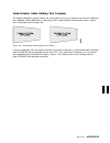
Figure 202. Eia rack template for models c11 and c12 inst installation inst-15.
Page 276
This page left intentionally blank inst-16 ibm 3570 mi.
Page 277
2. Position the shipping container that contains the 3570 in front of the rack. 3. Position the rack and locate the physical area in the rack where the 3570 is to be installed. Note: because of the weight of the 3570, it is recommended that the 3570 be installed as low as possible in the rack. The 3...
Page 278
Installing supporting slides and tray in rack when installing the library models in a rack, 6 eia rack units must be available. 1. Determine which rack location the 3570 will be installed in. Count and mark the 6 eia units on the left and right sides of the front and the rear of the rack. 2. See fig...
Page 279
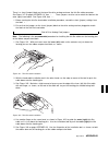
5. See figure 204. Install the right-hand slide and tray assembly 4 . A. Install the 2 nut-plates 1 , using 4 screws 2 , p/n 1624778, in the bottom eia units on the right side, as shown. Leave the screws loose enough to be able to insert the slide mounting brackets 3 under the nut-plates. B. Raise t...
Page 280
D. See figure 205. Lower the left side of the tray down so the tabs on the tray 1 set on the top of the left-hand slide assembly 3 . The brackets on the right-hand side should slide all the way under the nut-plates. Figure 205. Attaching tray to left-hand slide 6. See figure 206. Pull the tray and s...
Page 281
10. Ensure that all of the 7mm hex-head screws holding the slides to the rack are tight. 11. Ensure that the slides operate properly. They should extend all the way out without binding or rubbing on the rack frame. Loosen the screws and adjust the slide mounting brackets, if necessary. 12. See figur...
Page 283
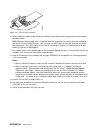
Figure 208. Sliding strap under drive inst 6. Attach the sling to the hoist. Attention: the balance point of the 3570 is toward the rear of the 3570. 7. Raise the 3570 slightly to check for proper balance. If required, lower the 3570 and readjust the position of the sling. 8. See figure 209 on page ...
Page 284
Figure 209. Raising 3570 using hoist end of rack hoist only with assistance only 15. Extend the slide and tray assembly 2 all the way out so it is locked in the extended position. C5 caution when you are sliding the 3570 drive tray assembly in or out, make sure you do not get your hand caught betwee...
Page 285
Figure 210. Attaching the 3570 to the rack tray inst 19. Move the tray and slide assembly into and out of the rack several times to ensure that the slides operate without binding. 20. Ensure that the rack doors will close without hitting the 3570. Note: in some racks the angled operator panel may in...
Page 288
Inst-28 ibm 3570 mi.
Page 300
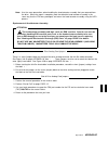
Installation checkout—library models before turning on power, the orange stopper shown in figure 218 must be removed from the unit. The stopper is pressed on the rail to prevent the picker from moving during shipping. To remove the stopper: 1. Unlock the library front door if necessary. The keys are...
Page 301
9. Power the device on. 10. Go to “operator panel setup and tests—library models.” operator panel setup and tests—library models 1 liquid crystal display screen 2 enter button 3 scroll down button 4 scroll up button 5 menu mode button figure 219. Operator panel, library models when the instructions ...
Page 302
6. Select cancel repeatedly until you return to the main menu. Set drive options—library models 1. Press the change mode push button to place the 3570 in ce mode. 2. Select drive 1 and press enter. 3. Select config/install from the ce options menu. 4. Select drv features from the config/install menu...
Page 303
Scsi attachment setting the scsi address and configuring the library the settings and configuration information selected in this procedure are saved in non-volatile memory and become the default settings after subsequent power-on cycles. This section describes how to: select the language used by the...
Page 304
10. Select address drv1 from the edit configuration menu and press enter. 11. Select the scsi address for tape drive 1 and press enter. For connection to as/400, scsi address 0 is recommended. After making your choice, select cancel and press enter to return to the edit configuration menu. Note: sel...
Page 305
26. Select the customer's desired mode of operation (manual, automatic, or random) for tape drive 2 and press enter. 27. Select cancel and press enter until the options menu is reached. 28. Continue at step 35. 29. If * unload drive is displayed, there is no cartridge in the drive. If unload drive (...
Page 306
For a detailed description, see “library operator panel” on page intro-40. Host (initiator) connection attention: the host (initiator) scsi port must be quiesced (varied off-line) before removing any scsi device. For as/400, only one scsi device is permitted per scsi initiator, and an as/400 system ...
Page 309
5. If the library is not the last device on this scsi bus, locate the scsi interface cable to the next device and connect it to the unused, rightmost scsi interface connector on the back of the library (see 2 in figure 224). Note: there are two scsi connectors on the back of the 3570 library. When t...
Page 311
10. If tape drive 1 is not the first device on the scsi bus, connect the scsi interface cable coming from the next closest device to the leftmost scsi connector on the back of tape drive 1. (see item 1 in figure 227 on page inst-52). 11. If tape drive 1 is the last device on the scsi bus, locate the...
Page 315
Split configuration (single host, one iop, one port) figure 232. As/400 fc 6501—split configuration (single host, one iop, one port) note: the cable connections are the same as for the base configuration. Split configuration (single host, one iop, both ports) figure 233. As/400 fc 6501—split configu...
Page 316
Split configuration (two hosts) figure 234. As/400 fc 6501—split configuration (two hosts) split configuration (single host, two iops) figure 235. As/400 fc 6501—split configuration (single host, two iops) 1 host (initiator) a, fc 6501 5 3570 tape drive 1 2 scsi connector 6 port 1 3 3570 tape drive ...
Page 317
Connecting the 3570 to multiple systems as/400 systems: as/400 systems cannot be interconnected using feature code 6501. Therefore a 3570 can only be attached to one as/400 system at a time. Rs/6000 systems: multiple rs/6000 systems may be linked to a 3570, but the systems cannot use the drive simul...
Page 318
Cable routing—rack-mounted models see figure 237 on page inst-59 for model c11, and figure 238 on page inst-60 for model c12. See figure 240 on page inst-61 for model c21, and figure 241 on page inst-62 for model c22. 1. Route the power and signal cables 2 through the strain relief clamp 1 and along...
Page 319
Figure 237. Cable routing, model c11 inst installation inst-59.
Page 320
Figure 238. Cable routing, model c12 figure 239. Cable length adjusting models c11 and c12 inst-60 ibm 3570 mi.
Page 324
Use the installp utility for installation. The software is always committed after installation. Insert the tape device driver/aix enhanced diskette into the diskette drive on the workstation. Note: you must have root authority to perform the commands in this section. To install the device driver, en...
Page 327
Repack instructions for the 3570 before repacking the 3570, verify that there is no tape cartridge inserted in the 3570. For the library, verify there are no tape cartridges loaded in the magazine. If there are cartridges present, remove them. To protect the tape drive loader mechanism during shippi...
Page 328
Inst-68 ibm 3570 mi.
Page 329: Common Procedures
Common procedures contents working with electrostatic discharge (esd) parts . . . . . . . . . . . . . . . . . . . . . . . . . . . Proc-3 fru removal and replacement procedures . . . . . . . . . . . . . . . . . . . . . . . . . . . . Proc-4 tools required . . . . . . . . . . . . . . . . . . . . . . . ...
Page 330
Updating microcode in drive 2 from fmr cartridge . . . . . . . . . . . . . . . . . . . . . . . . . Proc-36 updating microcode from fmr cartridge (drive-only models) . . . . . . . . . . . . . . . . . . . Proc-37 microcode ec level history log . . . . . . . . . . . . . . . . . . . . . . . . . . . . . ...
Page 331
This section contains the common procedures that are referenced from other sections of the manual. Working with electrostatic discharge (esd) parts see figure 243 on page proc-4. When wearing the esd grounding wrist band 1 , ensure that the ground clip 4 remains connected. Failure to do this creates...
Page 332
Figure 243. Static-sensitive device attention symbol and grounding wrist strap fru removal and replacement procedures each fru has its own specific format. A detailed illustration identified with numerals in reverse representation (for example, 1 ) indicates a part that must be removed. When a part ...
Page 333
Prepare the tape device for service 1. Notify the customer that the failing device must be varied off-line so the device power can be switched off. Note: both drives must be varied off-line for model c02 and model c12. It is not possible to service one drive while the other drive is being used. Proc...
Page 335
Verify fix you can run verify fix diagnostics on the device from the operator panel. See “verify fix—drive-only models” or “ce verify fix on library models” on page proc-10. You can also run the verify fix diagnostics from the host via the scsi send diagnostic command. Results of the tests will be r...
Page 336
5. If a cartridge is inserted within the 20+ second window, the appropriate option is initiated and the maintenance indicator led continues to flash during the test. 6. At the completion of a successful write/read test, the maintenance indicator turns off, and the clean led turns on solid. Press unl...
Page 337
Figure 246. Mapping of leds to fids on drive-only devices busy led 1 clean led 2 maintenance led 3 fid number of flashes in cycle 0 2 on solid dd 0 4 on solid e0 0 5 on solid e8 1 0 on solid b1 1 1 on solid ba 1 2 on solid bb 1 3 on solid bc 1 4 on solid c1 1 5 on solid c5 2 0 on solid b9 proc 2 2 o...
Page 338
2. After decoding the fid number from the flashing drive leds, go to “fid entry point” on page start-12 for further isolation. Ce verify fix on library models note: to run the verify fix diagnostics on drive-only models, see “verify fix—drive-only models” on page proc-7. Verify fix for these library...
Page 339
4. Press the scroll down push-button until the arrow head (>) points to the verify fix option. Select verify fix from the ce options menu, then select test drive from the ce verify fix menu. 5. The routine is executed in two parts: all of the (post) verification routines are executed. If no failures...
Page 340
Hardware reset in library models, a hardware reset equivalent to a power-on reset of the drive unit and library can be done from the operator panel by pressing the change mode push-button, the scroll up push-button and the enter push-button at the same time (change-mode+scroll-up+enter). In drive-on...
Page 341
6. You were asked to note the library mode that the customer was using, before you ran library diagnostics. You will need to return the library to the customer desired mode when you are done with this call. 7. Press the change mode push-button to place the device in operator mode. 8. Select set libr...
Page 342
Figure 248. Library sensors menu display, meanings and test methods menu display meaning and how to test >cancel + select to cancel routine * * * * * * * d r i v e s e n s o r s * * * * * * * ci:0 ub:0 cartridge inserted in loader and unload button. Manually load and unload a cartridge into the driv...
Page 343
Cartridge sensor pin locations the following graph depicts the locations of the cartridge sensor pins. The pins may be observed through the drive door at the front of the drive: fp ct ct ct ct (not to scale) legend: fp=file protect sense pin ct=cartridge type sense pins figure 249. Cartridge sensor ...
Page 345
Figure 251. Loading a cartridge in a magazine (with operator side facing down) proc common procedures proc-17.
Page 346
Removing tape cartridge from drive the following procedure should be used when removing a tape cartridge from a 3570 tape drive. Two conditions are defined; remove the tape cartridge with power on the device if possible, and removing a tape cartridge manually, with power off the device. Choose the c...
Page 348
Figure 252. Removing a stuck cartridge from a drive proc-20 ibm 3570 mi.
Page 350
Inserting or removing a cleaning cartridge 1. Change from the default status screen to the options menu by pressing the enter button. 2. Select the clean option and press enter. 3. If inserting a cleaning cartridge in the library, go to 5. 4. If removing a cleaning cartridge from the library, select...
Page 352
2. The labels must be oriented on the cartridge, as shown in figure 255 on page proc-24. The new cartridge labels must be placed totally within the recessed area on the tape cartridge. The label must be placed flat over the length of the label and cannot have folds, missing pieces, tears or have any...
Page 353
Initializing the tape volume serial number the cartridge label bar code on the magstar mp cartridge is unique and is used to identify each cartridge. For standard label tape processing using the bar code reader, the bar code labels and internally recorded volser must match. Most ibm tape management ...
Page 354
Some operating systems or applications, like adsm and brms/400, only display the last six characters (the media type "f" or "g" is not displayed). For standard label tape processing using the bar code, the bar code labels and internally recorded volser must match, if there are existing cartridges wh...
Page 355
Library configuration selection library configuration is only available on magstar mp models c02, c12 and c22. To change the configuration of a library unit, perform the following steps in the order indicated: 1. At power on, the status screen will be displayed. Press the enter button to display the...
Page 356
When the tape in the drive has been unloaded, the library will not automatically load the next cartridge into the drive. In order to resume operation, the operator must select start on the options menu. This operation is available only in automatic mode. Resetting the cartridge sequence in automatic...
Page 357
Drive serial number—library models only 1. Switch to ce mode by pressing the mode change push-button. 2. If you are working on a 2-drive library, select the drive number you are working on. 3. Select the config/install option. 4. Select the drv serial no option. 5. Select the disp serial no option t...
Page 358
Cancel 3 3 3 3 save and cont 9. Move the cursor to the digit you want to change and press enter. Note: you must enter the serial number in hex values, not ascii. 10. The ce choose value menu will appear so you can select the desired digit. Move the cursor to the desired digit and press enter. The da...
Page 359
Making fmr tape from scratch tape—library models this procedure creates an fmr tape from a scratch tape for library models. The scratch tape will contain the microcode that is active in the device. 1. Make a note of the library mode that the device is in. You will need to return the library to that ...
Page 360
For each led to determine which fid is being presented. The led counts arrive in approximately 1-second intervals. When all the led's flash in unison again, the count is about to begin again. This will continue until reset by power off. The fid meanings are shown in figure 246 on page proc-9. Refer ...
Page 361
Making scratch tape from fmr tape—drive-only models (unmaking fmr) this procedure cannot be performed on drive-only models. It is available only to library models. See “making scratch tape from fmr tape—library models (unmaking fmr).” proc common procedures proc-33.
Page 363
Isolate drive 1 / drive 2 communications fault if tape drive 1 cannot communicate with tape drive 2, or if the microcode installed in the tape drives are at different ec levels, the status accessing or xferring is never displayed on the bottom line of the operator panel display when the library is p...
Page 365
Updating microcode from fmr cartridge (drive-only models) the cartridge must not be file protected. This procedure automatically updates the field microcode replacement (fmr) tape with the microcode from the drive if the fmr tape does not contain the microcode and updates the microcode in the device...
Page 366
Microcode ec level history log figure 258 shows how to determine the ec level and link level of the microcode from the operator services menu. Use the link level 1 to determine the latest ec level. If you read the ec level and link level from the fmr tape (“updating microcode from fmr cartridge (lib...
Page 367
Error log analysis procedure the error log analysis procedure is designed to assist the service representative in isolation of intermittent failures, or chronic problems that seldom happen but occur often enough to cause a concern. We will use the error log to demonstrate how one might look for poss...
Page 368
Note: fid 97 only occurred in the columns in the right-hand portion of the work sheet, but that is because it was considered a low probability of failure when taken one fid at a time. If a fid occurs often, but always falls in a low probability position, that fid may be causing the problems but due ...
Page 369
Figure 260. Blank error log analysis work sheet proc common procedures proc-41.
Page 371
Figure 263. Example—error log analysis work sheet proc common procedures proc-43.
Page 372
Set error match trap (to get a dump) rs/6000 note: the aix tape and medium changer device driver provides an automatic dump facility. It automatically reads a dump from the 3570 when it is available and stores the dump in a directory on the rs/6000 system. See the problem determination chapter in th...
Page 373
Note: only three saved traps can be active at a time. If more than three are selected, the procedure will not be successful. To see how many saved traps are active, select saved traps from the ce ucode trap menu and then select the list saved fsc traps option. Remove error match trap note: this proc...
Page 374
This completes removal of a known, normal fsc trap. 4. Perform “end of call” on page proc-12 or return to the procedure that sent you here. Unknown normal error code 1. With the ce ucode traps menu displayed, select list fsc traps. The list is displayed. 2. Select the error code to be removed (from ...
Page 375
Off-loading dumps from 3570 to tape cartridge (library models) note: be sure to off-load dumps for both drive 1 and drive 2 in models c02 and c12. Both dumps can be copied to the same scratch tape. The dump icon ! Appears when the dump is available and remains on the screen to indicate that dump dat...
Page 376
Off-loading dumps from 3570 to tape cartridge (drive-only models) rs/6000 note: the aix tape and medium changer device driver provides an automatic dump facility. It automatically reads a dump from the 3570 when it is available and stores the dump in a directory on the rs/6000 system. See the proble...
Page 377
Updating microcode from an as/400 microcode load for the 3570 tape drives directly attached to an as/400 with the scsi is obtained from the as/400 using the program temporary fix (ptf) process. Note: if the magstar mp model c02 or c12 is in split configuration, microcode update is not supported usin...
Page 378
Updating microcode from rs/6000 by using tapeutil you may require assistance from the customer during this process. Note: if updating microcode in a magstar mp 3570 model c02 or c12, update the microcode in drive 2 before drive 1. Both tape drives in the 3570 must be at the same microcode level for ...
Page 379
8. If loading the microcode from the diskette reader, press f7=commit from the following panel. Otherwise, enter the path and filename and press f7=commit. Enter the filename /xxx.Yyyy in the source field where xxx.Yyyy is the filename of the microcode file to be loaded. For example, type /762.Fmrz....
Page 380
Off-loading dumps from 3570 to rs/6000 by using tapeutil note: be sure to off-load dumps for both drive 1 and drive 2 in models c02 and c12. The dump icon ! Appears when the dump is available, and remains on the screen to indicate that trace data is stored in the device. Note: trace data is volatile...
Page 381
9. Select a device and press f7=commit from the following panel. You must press f7=commit after selecting the drive. Ibm tape device selection menu. 9 select one of the devices listed below. Name location type rmt2 - 5- 1-1 ibm 357 tape drive and medium changer rmt3 - 5- 1-3 ibm 357 tape drive and m...
Page 392
Mapping element addresses to physical locations each physical location capable of holding a tape cartridge is assigned an element address value. The physical cartridge locations and their element address values are shown in figure 265. (figure 265 is a top view of the library with the back at the to...
Page 393
Checking the scsi attachment in an as/400 environment if you are having problems with your connection to an as/400, review the following hints for possible causes, then continue with the scsi checkout: proc common procedures proc-65.
Page 394
As/400 hints: ptfs are required prior to attaching a 3570 magstar mp tape subsystem to an as/400 system. The ptfs for all supported as/400 releases are listed in info apar ii10363. This information apar contains the most current ptf information for all supported releases and important information co...
Page 395
As/400 scsi checkout to verify that a 3570 is attached properly to an as/400, do the following: 1. Type wrkcfgsts *dev astlvl(*basic) at the prompt. The following screen appears, which shows all of the attached tape device names. In this example, tap13 1 is the device name to use for vfytap. Work wi...
Page 396
6. When the tape device test menu is displayed, select exit test menu 3 . Proc-68 ibm 3570 mi.
Page 397
Checking the scsi attachment in an aix environment the devices must be fully installed and the host device drives must be configured and available. If you are not familiar with rs/6000, you may want to ask the system operator to configure and make available the drive or drives you wish to test if th...
Page 398
2. Type tapeutil and the following menu appears: general commands: 1. Open a device 5. Inquiry 9. Log sense page 2. Close a device 6. Test unit ready 1 . Mode sense page 3. Device info 7. Reserve device 11. Release device 4. Tape drive service aids 8. Request sense q. Quit program medium changer com...
Page 399
Read and write tests load a scratch cartridge in the 3570 before you start this test. Attention: this test overwrites any data or tape label on the tape. 1. If the response from the previous test is hit any key to continue...; press enter. Otherwise, type tapeutil to restart. General commands: 1. Op...
Page 400
General commands: 1. Open a device 5. Inquiry 9. Log sense page 2. Close a device 6. Test unit ready 1 . Mode sense page 11. At the enter selection for /dev/rmt1: prompt, type 2. At the device closed... Hit any key to continue... Prompt, press enter. General commands: 1. Open a device 5. Inquiry 9. ...
Page 404
Checking the scsi attachment in a hp-ux environment tapeutil refer to ibm scsi tape drive, medium changer, and library device drivers: installation and user's guide gc35-0154 for details of the tapeutil program in the hp-ux system. The devices must be fully installed and the host device drives must ...
Page 405
Scsi port wrap test use only p/n 05h9163 for the scsi wrap test; using the wrong wrap tool may cause the 3570 to not run the wrap test. Note: wrap tool p/n 05h9163 is not shipped with the machine but is available from your service branch. To perform the scsi wrap test on drive 1, continue at “scsi w...
Page 406
C. Select the config/install menu. See “ce options menu” on page panel-29. D. Select the wrap tools option. See “ce config/install menu” on page panel-39. E. Observe the display for scsi wrap feedback. See “ce wrap tools menu” on page panel-41 if the display shows scsi: prsnt, the wrap plug was dete...
Page 407
Scsi bus problem determination use the “solid errors” or the “intermittent errors” on page proc-81 procedure. Solid errors determine the number of drives on the scsi bus. Single tape drive on scsi bus 1. Check to see if drive power is on. 2. Check to see if the drive scsi address is the same as the ...
Page 410
2. Obtain the errors that the device reported to the host. For example, if the device is attached to a rs/6000, run tapeutil. Select option 9, error log analysis. Gather all possible error information. Note: if you run a scsi bus trace tool and you have more than one drive running, the non-failing d...
Page 411
2. Start the trace of the next failure. For example, if you are using the aix tape device driver, type atrc to start the trace. 3. Trace only the failing drive or run only the failing drive. 4. Connect the scsi bus trace tool if a failure occurs. 5. On the next failure, get a 3570 microcode dump and...
Page 412
Fid e5—microcode problem note: for drive only models, get the support data from the host. If fid e5 is currently displayed on the drive, go to step 1. If fid e5 is not currently displayed on the drive, go to step 2. 1. If fid e5 is currently displayed on the drive: a. From fid display, write down th...
Page 413
C. For new microcode problems, a dump is needed. Check with customer to determine if they had collected a dump via scsi for this problem when the fid and the dump icon was displayed. See “microcode dump procedures” on page proc-85. If the customer has the dump information, provide the dump, the fid,...
Page 414
Fid e6 or e7—isolate fault between microcode and hardware note: for drive only models, get the support data from the host. Fid e6 can be displayed with several lines of support data (abnormal condition). If fid e6 or fid e7 is displayed use “fid e6, e7—normal fid display procedure.” fid e6, e7—norma...
Page 415
A. If you get a new or a different fid, go to the start section with that information. B. If you get the same fid (e6 or e7), a hardware problem exists. Do not save the microcode dump. Perform actions for next fru in the fid list. C. If an error does not occur, the fault could be a new microcode pro...
Page 416
B. If the dump icon is also displayed, the customer can retrieve a dump via scsi (if host device driver software supports). C. If the dump icon is not displayed, the customer can select force error dump (operator services menu), which will provide a fid ff and the dump icon. Fid ff indicates that a ...
Page 419
No response from operator/ce panel and no message 1. If hung/frozen panel was reported by customer but does not currently exist on drive, ask the customer if they can readily recreate the failure. If they cannot recreate the failure or it is an inconvenient time for the customer, have them call for ...
Page 420
Proc-92 ibm 3570 mi.
Page 421
Checks, adjustments, removals, and replacements contents introduction . . . . . . . . . . . . . . . . . . . . . . . . . . . . . . . . . . . . . . . . . . . . . . . . . Carr-2 removal and replacement procedures—external covers . . . . . . . . . . . . . . . . . . . . . . Carr-3 library chassis covers ...
Page 422
Introduction this section contains the information necessary to find, check, adjust if necessary, and exchange the failing field replaceable unit (fru). The fid (fru identifier) numbers are listed in hexadecimal ascending order in figure 8 on page start-12. You may be directed to the start section, ...
Page 423
Removal and replacement procedures—external covers note: when you are removing a cover to access frus inside the machine, you may want to complete your testing prior to replacement of these covers, in case the fru you replaced did not fix the problem. Library chassis covers removal of library chassi...
Page 424
Figure 270. Library model c01—exploded view carr-4 ibm 3570 mi.
Page 425
Decorative cover—drive-only models the decorative cover 2 of drive-only models must be removed for access to most frus in the drive. See figure 271. Removing the decorative covers—drive-only models 1. From the rear of the unit, remove and save the 3 screws, items 3 (two screws not shown), that hold ...
Page 426
3. Reattach the drive front cover. Observe the detents in the front of the chassis as the front cover is engaged to the top cover with tabs 1 . Carr-6 ibm 3570 mi.
Page 430
Fid b3—drive pack, drive-only models note: this procedure applies only to non emea countries and regions that support the drive pack as a single fru. Emea countries should be using the procedure at “appendix d” on page appendd-1. Removal of drive pack from chassis: to remove the physical drive follo...
Page 431
Removal and replacement procedure—drive pack covers drive assembly front cover removal of drive assembly front cover: see figure 274 on page carr-15 for an exploded view of the drive pack. To remove the drive assembly front cover, item 13 , follow the steps below if not done before: 1. “prepare the ...
Page 432
Replacement of drive assembly top cover 1. Perform the replacement procedure in the reverse order. 2. Return to the procedure that sent you here. Removal and replacement procedure—cooling pack note: when you are removing the cooling pack to access parts inside the drive, you may want to complete you...
Page 433
Removal of drive cooling fan 1. Prepare the drive for service. 2. Preform “fid b3—drive pack, library models” on page carr-7 for library models, or “fid b3—drive pack, drive-only models” on page carr-10 for drive-only models. 3. Perform “fid b2: cooling pack” on page carr-12 then return here. 4. Rem...
Page 434
Removal and replacement procedures—base drive components before performing any recommended removal or replacement procedures, you should complete the following procedures that apply to the model of 3570 you are here to repair: note: the removal and replacement time estimate in the last column of the...
Page 435
Figure 274. Base drive fru breakout carr checks, adjustments, removals, and replacements carr-15.
Page 436
Fid c1: power supply removal of the power supply: electrical shock potential in this area. Ensure that the 3570 power cord is removed from the customer power source before proceeding. 1. Perform the “prepare the tape device for service” on page proc-5 procedure, then return here. 2. Perform the “lib...
Page 437
Fid cb: internal scsi cable removal of internal scsi cable 1. Prepare the drive for service. 2. Perform “fid b3—drive pack, library models” on page carr-7 for library models, or “fid b3—drive pack, drive-only models” on page carr-10 for drive-only models. 3. Perform “fid b2: cooling pack” on page ca...
Page 439
Removal and replacement procedures for the library the following removal and replacement procedures are for all models of the library and are listed by fid order. Fid 90: library operator panel display removal of library operator panel display 1. “prepare the tape device for service” on page proc-5....
Page 440
Fid 92: accessor assembly removal of accessor assembly 1. Perform the “fid 9a: picker assembly” on page carr-23 removal procedure, then return here. 2. Refer to figure 276 on page carr-22, item f, and remove the cable between the library control card and accessor motor assembly (cd6) from the librar...
Page 441
4. Reconnect the connector 1 . Figure 275. Barcode reader carr fid 95: accessor motor assembly removal of accessor motor assembly note: shiny picker belts can cause fid 95 failures due to infrared light reflecting from the belts onto the cartridge present sensor. If the picker belts must be cleaned ...
Page 442
Fid 97: library control card removal of library control card note: attention: the logic cards are esd sensitive. Special care must be used when handling esd parts. See “working with electrostatic discharge (esd) parts” on page proc-3. Refer to figure 276 for a pictorial of the cable connections for ...
Page 443
Fid 99: picker cable removal of picker cable 1. “prepare the tape device for service” on page proc-5. 2. Refer to figure 276 on page carr-22, item c, and disconnect the cable connector (cd3) from the library control card by releasing the lock on the bottom of the connector. 3. Disconnect the picker ...
Page 444
Figure 277. Library global sensor component identification and locations figure 278. Library global sensor component plastic covers carr-24 ibm 3570 mi.
Page 445
Fid 9b: drive global sensor pair removal of drive global sensor pair note: when replacing any part of the drive global sensor pair, replace both the sensor and the light source at the same time. Be aware that the two parts look very much alike and will not work if interchanged. Refer to figure 277 o...
Page 446
Fid 9c: magazine global sensor pair removal of magazine global sensor pair note: when replacing any part of the magazine global sensor pair, replace both the sensor and the light source at the same time. Be aware that the two parts look very much alike and will not work if interchanged. Refer to fig...
Page 450
Removal of library front cover assembly (old style) 1. “prepare the tape device for service” on page proc-5. 2. Remove the library operator panel display assembly by tilting out from the top. 3. Disconnect the library operator panel display cable from the library operator panel display. 4. Set the l...
Page 452
Fid a0: magazine 2 sensor removal of magazine 2 sensor 1. “prepare the tape device for service” on page proc-5. 2. Remove the magazine if present. 3. Disconnect the cable from the sensor. 4. Remove the screw securing the sensor to the mounting plate. 5. Remove the sensor. Replacement of magazine 2 s...
Page 453
4. Return to the procedure that sent you here. Fid a3: cleaner cartridge-present sensor removal of cleaner cartridge-present sensor 1. “prepare the tape device for service” on page proc-5. 2. Remove the two screws securing the cleaner cell to the bracket. These screws may be seen easily from the fro...
Page 454
Fid a6: library led card removal of library led card 1. “prepare the tape device for service” on page proc-5 and then return here. 2. Perform removal of the “library chassis covers” on page carr-3. 3. Perform removal of the “fid 9d: library front cover assembly” on page carr-27. 4. With the front co...
Page 455
Fid db: ac switch and cable assembly removal of library door open sensor 1. “prepare the tape device for service” on page proc-5 and then return here. 2. Perform removal of the “library chassis covers” on page carr-3. 3. Perform removal of the “fid 9d: library front cover assembly” on page carr-27. ...
Page 456
Carr-36 ibm 3570 mi.
Page 475: Appendb
Appendb contents the ibm magstar mp 3570 tape subsystem . . . . . . . . . . . . . . . . . . . . . . . . . . . . Appendb-2 drive—only models . . . . . . . . . . . . . . . . . . . . . . . . . . . . . . . . . . . . . . . . . Appendb-2 library models . . . . . . . . . . . . . . . . . . . . . . . . . . ....
Page 476
The ibm magstar mp 3570 tape subsystem attention this section of the appendix contains the start section which handles individual frus within the model “c” drive. All areas except emea now replace the 3570 model c drive as a single fru. Emea has chosen to maintain multiple frus and therefore should ...
Page 477
Library models the ibm magstar mp 3570 tape subsystem library model is pictured in figure 297. When procedures in this manual are unique for library models, you will be referred to library procedures. Note: in models c02, c12 and c22, tape drive 1 is on the right and tape drive 2 is on the left, as ...
Page 478
Maintenance starting point begin all maintenance action here if you are in emea. Select the table below that best describes the 3570 model that you are here to work on. The two major model types are shown in figure 296 on page appendb-2 and figure 297 on page appendb-3. For 3570 drives without a lib...
Page 479
Figure 298 (page 2 of 2). Start—for all drive-only models without library attachments if you are here for this reason perform this action a host or channel detected problem. (no fid message) 1. Run the verify fix diagnostics using a scratch cartridge to test the read/write function. See “verify fix—...
Page 480
Figure 299 (page 2 of 2). Start—all library models if you are here for this reason perform this action a host or channel detected problem. (no fid message) 1. Run the verify fix diagnostics using a scratch cartridge to test the read/write function. See “ce verify fix on library models” on page proc-...
Page 481
Start for library and drive-only common entries figure 300 (page 1 of 3). Start—here for common entries not previously listed if you are here for this reason perform this action all three drive led indicators are on solid or library leds flash continuously. Note: this is normal for a few seconds at ...
Page 482
Figure 300 (page 2 of 3). Start—here for common entries not previously listed if you are here for this reason perform this action 1. Microcode update-from fmr cartridge 2. Microcode update-from as/400 3. Microcode update-from rs/6000 4. Microcode update-from sun 5. Microcode update-from hp/ux 6. Mic...
Page 483
Figure 300 (page 3 of 3). Start—here for common entries not previously listed if you are here for this reason perform this action repair a 3570 model without a fid number or attention message. Go to “other obvious symptom problems—emea only” on page appendc-21 to perform further problem determinatio...
Page 484
Drive indicators—normal operation for drive-only models for drive-only models without a library attachment, three leds indicate operator messages and error conditions under normal customer operations. Figure 301 shows the location of the operator panel indicators. See “drive indicators and operator ...
Page 485
Figure 302. Indicator meaning during normal operational conditions busy 1 clean 2 maintenance 3 note message off off off — inactive off off flashing 1 post or write/read diagnostic test running off flashing off 2 cleaning is required off on off 2 the drive has been disabled until the head cleaning p...
Page 487
Figure 303 (page 2 of 11). Fids, frus, and tacs reported fid repair sequence fru name prob- ability tac code & (duration in hours) page reference or instruction 90 electronic fault. See also “library operator panel problems—emea only” on page appendc-3. 1 library operator panel display 50% l05 (0.2)...
Page 488
Figure 303 (page 3 of 11). Fids, frus, and tacs reported fid repair sequence fru name prob- ability tac code & (duration in hours) page reference or instruction 97 electronic-detected fault 1 library control card 70% t15 (0.1) appendd-42 2 drive logic card 25% l01 (0.5) appendd-15 3 library interfac...
Page 489
Figure 303 (page 4 of 11). Fids, frus, and tacs reported fid repair sequence fru name prob- ability tac code & (duration in hours) page reference or instruction 9e sensor did not change state. Note: before replacing frus below, ensure that the appropriate sensors are operating correctly. See figure ...
Page 490
Figure 303 (page 5 of 11). Fids, frus, and tacs reported fid repair sequence fru name prob- ability tac code & (duration in hours) page reference or instruction a7 picker or priority slot error. Note: before replacing any frus below, inspect the cartridge that was being used when the error occurred ...
Page 491
Figure 303 (page 6 of 11). Fids, frus, and tacs reported fid repair sequence fru name prob- ability tac code & (duration in hours) page reference or instruction ba loader asm or servo card 1 loader assembly 50% t45 (1.6) appendd-30 2 drive servo card 45% t53 (1.0) appendd-28 3 drive logic card 3% l0...
Page 492
Figure 303 (page 7 of 11). Fids, frus, and tacs reported fid repair sequence fru name prob- ability tac code & (duration in hours) page reference or instruction ca sensor failed to change state note: before replacing frus below, ensure that the appropriate sensors are operating correctly. See figure...
Page 493
Figure 303 (page 8 of 11). Fids, frus, and tacs reported fid repair sequence fru name prob- ability tac code & (duration in hours) page reference or instruction d8 read/write error. (d08=clean only, t22=replace) 1 drive servo card 54% t53 (1.0) appendd-28 2 head-actuator assembly 36% d08/ t22 (0.8) ...
Page 494
Figure 303 (page 9 of 11). Fids, frus, and tacs reported fid repair sequence fru name prob- ability tac code & (duration in hours) page reference or instruction e7 timing problem in the microcode or the electronics 1 microcode (known or new) (m01 = known, m02 = new) 50% m01/ m02 proc-84 and proc-86 ...
Page 495
Figure 303 (page 10 of 11). Fids, frus, and tacs reported fid repair sequence fru name prob- ability tac code & (duration in hours) page reference or instruction f0 read error— drive logic card, drive analog card, tape cartridge, head-actuator assembly, or mother board 1 tape cartridge 60% d07 (0.1)...
Page 496
Figure 303 (page 11 of 11). Fids, frus, and tacs reported fid repair sequence fru name prob- ability tac code & (duration in hours) page reference or instruction f5 scsi bus error (drive logic card or scsi cables) 1 scsi interface, operator procedural, or host problem — — run the scsi wrap test. See...
Page 497
Attention drive messages—emea only library machines: 1. Some attention messages (attention drive) have an associated fid that is not displayed until you press the enter push button. 2. Use figure 304 for attention drive messages without an associated fid. 3. If attention drive is displayed, press th...
Page 498
Attention library messages—emea only some attention messages (attention library) have an associated fid that is not displayed until you press the enter push button. Use figure 305 for attention library messages without an associated fid. 1. If attention library is displayed, press the enter push but...
Page 499
Figure 305 (page 2 of 5). Attention library messages message meaning frus fru name or description prob- ability tac code & (duration in hours) page reference or instruction clear picker path b the device detected the presence of a possible blockage in the cartridge path between the drive and the pic...
Page 500
Figure 305 (page 3 of 5). Attention library messages message meaning frus fru name or description prob- ability tac code & (duration in hours) page reference or instruction extra cartridge the device loaded a cartridge from the magazine and detected that another cartridge was placed in its home posi...
Page 501
Figure 305 (page 4 of 5). Attention library messages message meaning frus fru name or description prob- ability tac code & (duration in hours) page reference or instruction magazine full the magazine is full of cartridges. The device detected that the magazine cannot hold any more cartridges. Note: ...
Page 502
Figure 305 (page 5 of 5). Attention library messages message meaning frus fru name or description prob- ability tac code & (duration in hours) page reference or instruction library door open the device detected that the library door was opened. Note: before replacing frus below, ensure that the libr...
Page 503: Appendix C
Appendix c contents library operator panel problems—emea only . . . . . . . . . . . . Appendc-3 library led problems—emea only . . . . . . . . . . . . . . . . . . . Appendc-5 drive led problems—emea only . . . . . . . . . . . . . . . . . . . . Appendc-9 power problems—emea only . . . . . . . . . . ....
Page 504
Appendc-2 ibm 3570 mi.
Page 505
Library operator panel problems—emea only this procedure helps you isolate library operator panel failures. See the appendd section for check, adjustment, removal, and replacement procedures for all machines located within emea. See “operator panel” on page panel-1 for a description of the operator ...
Page 506
Library operator panel problems—emea only (continued) 004 (continued) did the test fail? Yes no 005 go to step 011. 006 – switch power off and check that the library operator panel display cable connector from the library operator panel display to the library control card is seated properly. If the ...
Page 507
Library led problems—emea only this procedure helps you isolate library led failures. See the appendb section for check, adjustment, removal, and replacement procedures. See “operator panel” on page panel-1 for a description of the operator panel. Unless otherwise directed, run fix verify from the c...
Page 508
Library led problems—emea only (continued) 007 (continued) 4. Library interface cable (3%) at “fid a2: library interface cable” on page appendd-53. 5. Library sensor cable (2%) at “fid a5: library sensor cable” on page appendd-54. 008 (from page appendc-3) (from steps 002 and 025) some or all librar...
Page 509
016 (continued) 2. Cable from the power supply to the mother board (20%) 017 power is ok to the library control card which drives the library operator panel leds and library operator panel display. Replace the following frus in the order listed: 1. Library control card (50%) at “fid 97: library cont...
Page 510
Library led problems—emea only (continued) diagnostics are completed. Switch power off then on, and observe the library leds. Do all of them flash on and off? Yes no 024 do any of the 3 leds flash on and off? Yes no 025 continue at step 008 on page appendc-6. 026 replace the following frus in the or...
Page 511
Drive led problems—emea only this procedure helps you isolate drive led failures. See figure 302 on page appendb-11 for a description of the drive leds and their meaning during normal operational conditions. See “operator panel” on page panel-1 for a description of the operator panel. See the append...
Page 512
Drive led problems—emea only (continued) 007 (continued) this is a library model. Power off then on, and observe the 3 leds on the library operator panel. They should flash on and off until the power-on diagnostics are complete. Did any of the library leds flash on and off? Yes no 008 perform the fo...
Page 513
012 (continued) c. “drive assembly top cover” on page appendd-10. 2. If this is a drive-only model, perform the following removal procedures: a. “decorative cover—drive-only models” on page appendd-6. B. “fid b2: cooling pack” on page appendd-11. C. “drive assembly top cover” on page appendd-10. You...
Page 514
Drive led problems—emea only (continued) 1. If this is a library model, perform the following removal procedures: a. “library chassis covers” on page appendd-4. B. “fid b2: cooling pack” on page appendd-11. C. “drive assembly top cover” on page appendd-10. 2. If this is a drive-only model, perform t...
Page 515
Power problems—emea only this procedure helps you isolate power failures. See the appendb section for check, adjustment, removal, and replacement procedures. See “power supply” on page intro-16 for a description of 3570 power. Unless otherwise directed, run fix verify from the ce options menu to tes...
Page 516
Power problems—emea only (continued) 009 (continued) does the cooling fan switch on now? Yes no 010 is this a library device? Yes no 011 replace the “fid c1: power supply” on page carr-16. 012 switch power off, refer to figure 308 on page appendc-29, and disconnect the cable from the library control...
Page 517
020 (continued) 3. Drive servo card, see “fid ec: drive servo card and fid e9: mother board” on page appendd-28. (5%) 4. “fid eb: drive analog card” on page appendd-18. (5%) 5. “fid c1: power supply” on page appendd-35. (20%) 021 (from step 002) is this a library model? Yes no 022 this is a drive-on...
Page 518
Power problems—emea only (continued) 028 (continued) 1. “library chassis covers” on page appendd-4. 2. “fid b2: cooling pack” on page appendd-11. 3. “drive assembly top cover” on page appendd-10. Find the cable that runs from the power supply to the mother board, switch power off and remove the end ...
Page 519
035 (continued) does the drive pack fan rotate with power on? Yes no 036 replace the following frus in the order listed: 1. “fid be: drive cooling fan” on page appendd-11 (90%). 2. “fid c1: power supply” on page appendd-35 (9%). 3. Cable from the power supply to the drive pack fan (no fid) (1%). Not...
Page 520
Power problems—emea only (continued) 041 (continued) 2. Power supply (15%) at “fid c1: power supply” on page appendd-35. 3. Cable from the power supply to the drive pack fan (no fid) (5%). Note: an alternative to replacement of this cable is to disconnect both ends and continuity check the cable. If...
Page 521
Appendc appendix c appendc-19.
Page 522
Notes appendc-20 ibm 3570 mi.
Page 523
Other obvious symptom problems—emea only this map is intended to assist in repairing problems that are not your normal fid display, attention drive or attention library message. The device may be hung or have an unusual led display. Refer to figure 307 and attempt to find the failure symptom. Some c...
Page 524
Other obvious symptom problems—emea only (continued) 001 (continued) 3. The library operator panel display has only two dark lines displayed. With power on, inspect the library leds, the drive fan that exhausts through the rear of the device, and any other part you can see, hear or feel (the drive l...
Page 525
006 (continued) are any drive leds on solid continuously? Yes no 007 drive leds are working correctly. The problem must be only with the library leds. Perform the following remove procedures: 1. “library chassis covers” on page appendd-4. 2. “fid b2: cooling pack” on page appendd-11. 3. “drive assem...
Page 526
Other obvious symptom problems—emea only (continued) operator options menu by selecting services, and then statistics. Too frequent clean requests may be caused by too many errors occurring during r/w operations. Ensure that the customer cleaner cartridge is not worn out. If it has not been replaced...
Page 527
017 (continued) 1. “decorative cover—drive-only models” on page appendd-6. 2. “fid b2: cooling pack” on page appendd-11. 3. “drive assembly top cover” on page appendd-10. Replace the following frus in the failing drive in the order listed: 1. Drive logic card (40%) at “fid ea: drive logic card” on p...
Page 528
Other obvious symptom problems—emea only (continued) 020 (continued) 3. Mother board (5%) at “fid e9: mother board” on page appendd-29. 4. Library interface cable (5%) at “fid a2: library interface cable” on page appendd-53. When repairs are complete, go to “verify fix” on page proc-7 then go to “en...
Page 529
Removed from the library control card. Does the voltage check ok? Yes no 028 replace the following frus in the order listed: 1. Power supply (80%) at “fid c1: power supply” on page appendd-35. 2. Cable from the power supply to the library control card (20%) 029 power is ok to the library control car...
Page 530
Other obvious symptom problems—emea only (continued) power diagram. Unplug the power cable from mother board at connector cd3, and power the device on. Check for the appropriate voltages at the cable pins shown in the referenced figure. Does power check ok at the cable end? Yes no 033 power is missi...
Page 531
Diagrams referred to by maps note: all voltage tolerances are ± 5%. Cd5 +12 vdc 1 library power supply gnd 2 control gnd 3 card +5 vdc 4 figure 308. Library electronic power diagram connector cd3 +12 vdc 1 1 1 drive power supply gnd 2 2 2 mother gnd 3 3 3 board +5 vdc 4 4 4 figure 309. Drive electro...
Page 532
Appendc-30 ibm 3570 mi.
Page 533: Appendix D
Appendix d contents introduction . . . . . . . . . . . . . . . . . . . . . . . . . . . . . . . . . . . . . . . . . . . . . . . Appendd-3 removal and replacement procedures—external covers . . . . . . . . . . . . . . . . . . . . Appendd-4 library chassis covers . . . . . . . . . . . . . . . . . . . ....
Page 534
Fid a6: library led card . . . . . . . . . . . . . . . . . . . . . . . . . . . . . . . . . . . . Appendd-55 fid aa: library door open sensor . . . . . . . . . . . . . . . . . . . . . . . . . . . . . . . Appendd-55 fid db: ac switch and cable assembly . . . . . . . . . . . . . . . . . . . . . . . . ....
Page 535
Introduction attention this section of the appendix contains the carr section which handles individual frus within the model “c” drive. All areas except emea now replace the 3570 model c drive as a single fru. Emea has chosen to maintain multiple frus and therefore should use this section when point...
Page 536
Removal and replacement procedures—external covers note: when you are removing a cover to access frus inside the machine, you may want to complete your testing prior to replacement of these covers, in case the fru you replaced did not fix the problem. Library chassis covers removal of library chassi...
Page 537
Figure 312. Library model c01—exploded view appendd appendix d appendd-5.
Page 538
Decorative cover—drive-only models the decorative cover 2 of drive-only models must be removed for access to most frus in the drive. See figure 271 on page carr-5. Removing the decorative covers—drive-only models 1. From the rear of the unit, remove and save the 3 screws, items 3 (two screws not sho...
Page 539
Removal and replacement procedures—drive pack drive pack, library models removal of drive pack from chassis: to remove the physical drive follow the steps below: 1. “prepare the tape device for service” on page proc-5 and then return here. 2. Perform removal of the “library chassis covers” on page a...
Page 540
Drive pack, drive-only models removal of drive pack from chassis: to remove the physical drive follow the steps below: 1. “prepare the tape device for service” on page proc-5 and then return here. 2. Perform removal of the “decorative cover—drive-only models” on page appendd-6. 3. Remove the followi...
Page 541
Figure 315. Basic drive—all models appendd appendix d appendd-9.
Page 542
Removal and replacement procedure—drive pack covers drive assembly front cover removal of drive assembly front cover: see figure 317 on page appendd-14 for an exploded view of the drive pack. To remove the drive assembly front cover, item 13 , follow the steps below if not done before: 1. “prepare t...
Page 543
Replacement of drive assembly top cover 1. Perform the replacement procedure in the reverse order. 2. Return to the procedure that sent you here. Removal and replacement procedure—cooling pack note: when you are removing the cooling pack to access parts inside the drive, you may want to complete you...
Page 544
Removal of drive cooling fan 1. Prepare the drive for service. 2. Preform “drive pack, library models” on page appendd-7 for library models, or “drive pack, drive-only models” on page appendd-8 for drive-only models. 3. Perform “fid b2: cooling pack” on page appendd-11 then return here. 4. Remove th...
Page 545
Removal and replacement procedures—base drive components before performing any recommended removal or replacement procedures, you should complete the following procedures that apply to the model of 3570 you are here to repair: note: the removal and replacement time estimate in the last column of the...
Page 546
Figure 317. Base drive fru breakout appendd-14 ibm 3570 mi.
Page 547
The following base drive removal and replacement procedures apply to all 3570 cxx models located in emea, and are listed in the most logical order of a typical repair action: fid ea: drive logic card removal of drive logic card: to remove the drive logic card, item 2 in figure 317 on page appendd-14...
Page 548
Note: do not forget to reconnect the flat cable, item 14 , between the drive logic card and the drive analog card. 2. After installing the new card, restore power to the 3570 tape subsystem. 3. If the power-on test completed successfully, go to step 4. Or, if the power-on test did not complete succe...
Page 549
15. Return to the procedure that sent you here. Replacement of drive logic card—drive-only models 1. Perform the removal procedure in the reverse order, then return here. 2. After installing the new card, restore power to the 3570 tape subsystem. 3. If the power-on test completed successfully, go to...
Page 550
Fid eb: drive analog card removal of drive analog card: attention the head-actuator assembly and logic cards are esd sensitive. Special care must be used when handling esd sensitive parts to be sure that no esd damage occurs. See “working with electrostatic discharge (esd) parts” on page proc-3 for ...
Page 551
Figure 318. Base drive head-actuator assembly close-up appendd appendix d appendd-19.
Page 552
Replacement of drive analog card: attention the head-actuator assembly and logic cards are esd sensitive. Special care must be used when handling esd sensitive parts to be sure that no esd damage occurs. See “working with electrostatic discharge (esd) parts” on page proc-3 for details. Do not use an...
Page 553
There is a shunt (jumper) block on the top of the drive analog card near the thin-film cable connector. See figure 317 on page appendd-14, item 1 . These jumpers must be set to match the label on the outer (right) head cable. See figure 320, item 2 . 1. Before starting the thin-film head cable insta...
Page 554
Figure 323. Thin-film cable installation 6. While holding the cables in place with the installation tool, plug the drive analog card into the mother board connector. Hint: when the drive analog card is in position over the connector, you can let go of the installation tool and it will stay in place ...
Page 555
Head-actuator cable holding tool template the following templates may be used by the service person to use as a pattern to cut out from moderately thin cardboard (.040 to .060 inches) a tool that may be used to keep the head-actuator cables in place when removing the drive analog card. Figure 324. H...
Page 556
Head-actuator cable holding tool template this page left intentionally blank. Appendd-24 ibm 3570 mi.
Page 557
Appendd appendix d appendd-25.
Page 558
Fid d0: head-actuator assembly this procedure uses a 2.5 mm allen wrench. Removal of head-actuator assembly: attention the head-actuator assembly and logic cards are esd sensitive. Special care must be used when handling esd sensitive parts such as the head-actuator assembly to be sure that no esd d...
Page 559
Note: use the same precautions when handling the head-actuator assembly that you removed from the drive. When the repair is complete, pack the defective head-actuator assembly in the same way that the fru was packaged, and return the head-actuator assembly using the upr process. Replacement of head-...
Page 560
Fid ec: drive servo card and fid e9: mother board removal of the drive servo card and mother board: attention the head-actuator assembly and logic cards are esd sensitive. Special care must be used when handling esd sensitive parts to be sure that no esd damage occurs. See “working with electrostati...
Page 561
Replacement of drive servo card and mother board: attention the head-actuator assembly and logic cards are esd sensitive. Special care must be used when handling esd sensitive parts to be sure that no esd damage occurs. See “working with electrostatic discharge (esd) parts” on page proc-3 for detail...
Page 562
Fid bc: loader assembly removal of the loader assembly: attention do not use any magnetized tools on or near the head assembly (including thin film cables). Magnetized tools will damage the head! Note: do not use any magnetized tools on or near the head assembly (including thin film cables) as they ...
Page 563
Figure 326. Drive loader assembly exploded view appendd appendix d appendd-31.
Page 564
Fid da: drive sensor cable removal of the drive sensor cable: to remove the drive sensor cable follow the steps below if not done before: 1. Perform the prerequisite procedures for your 3570 model listed on figure 316 on page appendd-13. 2. Perform removal of the “fid ea: drive logic card” on page a...
Page 565
Fid b0: loader door removal of loader door 1. Perform the prerequisite procedures for your 3570 model listed on figure 316 on page appendd-13. Note: the loader door may be removed without removing the cooling pack. 2. Pull the front cover forward. It should slide off. Note: be sure to install the co...
Page 566
Fid b1: drive led card removal of drive led card 1. Perform the prerequisite procedures for your 3570 model listed on figure 316 on page appendd-13. Note: the drive led card may be removed without removing the drive pack and cooling pack. A. For library models, perform removal of the “library chassi...
Page 567
Fid c1: power supply removal of the power supply: electrical shock potential in this area. Ensure that the 3570 power cord is removed from the customer power source before proceeding. 1. Perform the “prepare the tape device for service” on page proc-5 procedure, then return here. 2. Perform the “lib...
Page 568
Fid c9: loader door open sensor removal of loader door open sensor 1. Perform the prerequisite procedures for your 3570 model listed on figure 316 on page appendd-13. Note: the loader door open sensor may be removed without removing the cooling pack. 2. Pull the front cover forward. It should slide ...
Page 569
3. If this part is being replaced with a new part, use your local procedures to report the fru part number for the fid and use technical area code (tac) t31 for the area of failure. 4. Return to the procedure that sent you here. Fid cb: internal scsi cable removal of internal scsi cable 1. Prepare t...
Page 570
Fid dd: loader sensors removal of loader sensors 1. The file protect, and cartridge type sensors are part of the loader assembly. Refer to “fid bc: loader assembly” on page appendd-30 for removal procedures. 2. The loader door open sensor is replaceable. Refer to “fid c9: loader door open sensor” on...
Page 571
Removal and replacement procedures for the library the following removal and replacement procedures are for all models of the library that are in emea and are listed by fid order. Fid 90: library operator panel display removal of library operator panel display 1. “prepare the tape device for service...
Page 572
Fid 92: accessor assembly removal of accessor assembly 1. Perform the “fid 9a: picker assembly” on page appendd-43 removal procedure, then return here. 2. Refer to figure 276 on page carr-22, item f, and remove the cable between the library control card and accessor motor assembly (cd6) from the lib...
Page 573
4. Reconnect the connector 1 . Figure 328. Barcode reader fid 95: accessor motor assembly removal of accessor motor assembly note: shiny picker belts can cause fid 95 failures due to infrared light reflecting from the belts onto the cartridge present sensor. If the picker belts must be cleaned for f...
Page 574
Fid 97: library control card removal of library control card note: attention: the logic cards are esd sensitive. Special care must be used when handling esd parts. See “working with electrostatic discharge (esd) parts” on page proc-3. Refer to figure 329 for a pictorial of the cable connections for ...
Page 575
Fid 99: picker cable removal of picker cable 1. “prepare the tape device for service” on page proc-5. 2. Refer to figure 329 on page appendd-42, item c, and disconnect the cable connector (cd3) from the library control card by releasing the lock on the bottom of the connector. 3. Disconnect the pick...
Page 576
Figure 330. Library global sensor component identification and locations figure 331. Library global sensor component plastic covers appendd-44 ibm 3570 mi.
Page 577
Fid 9b: drive global sensor pair removal of drive global sensor pair note: when replacing any part of the drive global sensor pair, replace both the sensor and the light source at the same time. Be aware that the two parts look very much alike and will not work if interchanged. Refer to figure 330 o...
Page 578
Fid 9c: magazine global sensor pair removal of magazine global sensor pair note: when replacing any part of the magazine global sensor pair, replace both the sensor and the light source at the same time. Be aware that the two parts look very much alike and will not work if interchanged. Refer to fig...
Page 584
Fid 9e: priority cell cartridge-present sensor removal of priority cell cartridge-present sensor 1. “prepare the tape device for service” on page proc-5. 2. Remove the magazine if present. 3. Disconnect the cable from the sensor. 4. Remove the two screws securing the sensor to the mounting plate. 5....
Page 585
Fid a0: magazine 2 sensor removal of magazine 2 sensor 1. “prepare the tape device for service” on page proc-5. 2. Remove the magazine if present. 3. Disconnect the cable from the sensor. 4. Remove the screw securing the sensor to the mounting plate. 5. Remove the sensor. Replacement of magazine 2 s...
Page 586
4. Return to the procedure that sent you here. Fid a3: cleaner cartridge-present sensor removal of cleaner cartridge-present sensor 1. “prepare the tape device for service” on page proc-5. 2. Remove the two screws securing the cleaner cell to the bracket. These screws may be seen easily from the fro...
Page 587
Fid a6: library led card removal of library led card 1. “prepare the tape device for service” on page proc-5 and then return here. 2. Perform removal of the “library chassis covers” on page appendd-4. 3. Perform removal of the “fid 9d: library front cover assembly” on page appendd-47. 4. With the fr...
Page 588
Fid db: ac switch and cable assembly removal of library door open sensor 1. “prepare the tape device for service” on page proc-5 and then return here. 2. Perform removal of the “library chassis covers” on page appendd-4. 3. Perform removal of the “fid 9d: library front cover assembly” on page append...
Page 589: Parts Catalog
Parts catalog how to use this parts catalog similar assemblies: if two assemblies contain a majority of identical parts, they are broken down on the same list. Common parts are shown by one index number. Parts peculiar to one or the other of the assemblies are listed separately and identified by des...
Page 590
Assemblies list base drive all models . . . . . . . . . . . . . . . . . . . . . . . . . . . . . . . . . . . . . . . . Parts-24 desktop drive model c00 . . . . . . . . . . . . . . . . . . . . . . . . . . . . . . . . . . . . . . . Parts-6 desktop library assembly, model c01 . . . . . . . . . . . . . ....
Page 591
Parts catalog parts catalog parts-3.
Page 592
Assembly 1: rackmount library assembly, model c11 parts-4 ibm 3570 mi.
Page 593
Asm– part index number units description 1– np rackmount library assembly, model c11 –1 1 cover, top (no color) –2 1 cleaner cartridge storage –2 05h2912 1 cleaner cartridge retention spring (not shown) –3 65f5407 1 micro switch, cleaner cartridge-present sensor –4 50g0322 1 power supply –5 05h9386 ...
Page 594
Assembly 2: desktop drive model c00 parts-6 ibm 3570 mi.
Page 595
Asm– part index number units description 2– np desktop drive model c00 –1 34g7753 1 cover, top –2 05h4558 1 drive pack –3 34g7752 1 front external drive bezel –4 65f5410 1 power on/off switch assembly –5 50g0322 1 power supply –6 np fan/scsi assembly –7 05h4559 1 drive cooling fan –8 05h3062 1 inter...
Page 597
Asm– part index number units description 3– np desktop library assembly, model c01 –1 34g7791 1 top cover-raven black –2 1 cleaner cartridge storage –2 05h2912 1 cleaner cartridge retention spring (not shown) –3 65f5407 1 micro switch, cleaner cartridge-present sensor –4 1 cover, top (no color) –5 5...
Page 599
Asm– part index number units description 4– np rackmount library assembly, model c12 –1 1 cover, top (no color) –2 1 cleaner cartridge storage –2 05h2912 1 cleaner cartridge retention spring (not shown) –3 65f5407 1 micro switch, cleaner cartridge-present sensor –4 50g0322 1 power supply power suppl...
Page 600
Assembly 4: (continued) –18 65f5397 1 rs-422 cable internal to drive. Drive 2 only and not shown. –19 65f5406 1 ac cable to power supply 2. Note: see figure 201 on page inst-14 for a detailed listing of the rack mounting hardware. Parts-12 ibm 3570 mi.
Page 601
Parts catalog parts catalog parts-13.
Page 603
Asm– part index number units description 5– np desktop library assembly, model c02 –1 34g7791 1 top cover-raven black –2 1 cleaner cartridge storage –2 05h2912 1 cleaner cartridge retention spring (not shown) –3 65f5407 1 micro switch, cleaner cartridge-present sensor –4 1 cover, top (no color) –5 5...
Page 604
Assembly 5: (continued) –21 50g0322 1 power supply (power supply for drive 2). –22 65f5399 1 rs-422 cable, du0-du1. Shown attached to rear of drive 2 –22 65f5397 1 rs-422 cable, internal to drive. Drive 2 only and not shown. –23 65f5406 1 ac cable to power supply 2. Parts-16 ibm 3570 mi.
Page 605
Parts catalog parts catalog parts-17.
Page 607
Asm– part index number units description 6– np rackmount library assembly, model c21 –1 1 cover, top (no color) –2 1 cleaner cartridge storage –2 05h2912 1 cleaner cartridge retention spring (not shown) –3 65f5407 1 micro switch, cleaner cartridge-present sensor –4 50g0322 1 power supply –5 05h9386 ...
Page 609
Asm– part index number units description 7– np rackmount library assembly, model c22 –1 1 cover, top (no color) –2 1 cleaner cartridge storage –2 05h2912 1 cleaner cartridge retention spring (not shown) –3 65f5407 1 micro switch, cleaner cartridge-present sensor –4 50g0322 1 power supply power suppl...
Page 610
Assembly 7: (continued) –18 65f5397 1 rs-422 cable internal to drive. Drive 2 only and not shown. –19 65f5406 1 ac cable to power supply 2. Note: see figure 201 on page inst-14 for a detailed listing of the rack mounting hardware. Parts-22 ibm 3570 mi.
Page 611
Parts catalog parts catalog parts-23.
Page 612
Assembly 8: base drive all models parts-24 ibm 3570 mi.
Page 613
Asm– part index number units description 8– np base drive all models –1 1 cover, drive top –2 08l6371 1 drive logic card –3 1 retainer –4 05h4022 1 drive analog card –5 1 thin film head cable –6 1 cable mounting block –7 1 shield –8 08l6273 1 drive servo card –9 1 bottom plate –10 05h4562 1 head-act...
Page 614
Parts-26 ibm 3570 mi.
Page 615: Part Number Index
Part number index part asm– number index page 05h2912 1–2 parts-5 3–2 parts-9 4–2 parts-11 5–2 parts-15 6–2 parts-19 7–2 parts-21 05h3062 2–8 parts-7 05h4022 8–4 parts-25 05h4539 1–13 parts-5 3–14 parts-9 4–13 parts-11 5–14 parts-15 6–13 parts-19 7–13 parts-21 05h4547 1–8 parts-5 3–9 parts-9 4–8 par...
Page 616
Part asm– number index page 34g7801 continued 6–9 parts-19 7–9 parts-21 45g0277 1–8 parts-5 1–8 parts-5 1–8 parts-5 3–9 parts-9 3–9 parts-9 3–9 parts-9 4–8 parts-11 4–8 parts-11 4–8 parts-11 5–9 parts-15 5–9 parts-15 5–9 parts-15 6–8 parts-19 6–8 parts-19 6–8 parts-19 7–8 parts-21 7–8 parts-21 7–8 p...
Page 617: Glossary
Glossary this glossary defines the special terms, abbreviations, and acronyms that are used in this publication. If you do not find the term you are looking for, refer to the index or to the dictionary of computing, new york: mcgraw-hill, 1994. A ac. Alternating current. Access method. A technique f...
Page 618
Channel command. An instruction that directs a data channel, control unit, or device to perform an operation or set of operations. Char. Character. Chk. Check. Cm. Centimeter. Command. A control signal that initiates an action or the start of a sequence of actions. Concurrent. Refers to diagnostic p...
Page 619
Equipment check. An asynchronous indication of a malfunction. Erep. Environmental recording, editing, and printing. Error log. A dataset or file in a product or system where error information is stored for later access. Esd. Electrostatic discharge. F fault symptom code (fsc). A hexadecimal code gen...
Page 620
Interblock gap (ibg). An area on a data medium to indicate the end of a block or physical record. Interface. A shared boundary. An interface might be a hardware component to link two devices or it might be a portion of storage or registers accessed by two or more computer programs. Interposer. The p...
Page 621
N n/a. Not applicable. Node. In a network, a point at which one or more functional units connect channels or data circuits. Nvs. Nonvolatile storage. A storage device whose contents are not lost when power is cut off. O oem. Original equipment manufacturer. Offline. Pertaining to the operation of a ...
Page 622
Small computer system interface (scsi). An input and output bus that provides a standard interface between the host system and the 3570. Sns. Sense. Special feature. A feature that can be ordered to enhance the capability, storage capacity, or performance of a product, but is not essential for its b...
Page 623: Index
Index numerics 3570 introduction intro-3 3570 publications xi a ac grounding diagram insp-4 address menu panel-34 scsi port inst-9 set inst-41 address, scsi inst-43 aix checking scsi attachment proc-69 controller intro-36, intro-37 interposer intro-36, intro-37 trace failure proc-82 using tapeutil p...
Page 624
Drive (continued) features, menu panel-40 head cleaning proc-22 microcode ec level panel-39 model number panel-40 read/write test, option panel-30 serial number panel-39, panel-40, proc-29 serial number, menu panel-40 test, option panel-30 driver, device aix proc-69 hp-ux proc-76 publications xii su...
Page 625
Fmr (continued) instructions, make scratch tape (library models) proc-32 instructions, make tape (drive-only models) proc-31 instructions, make tape (library models) proc-31 instructions, update from tape proc-34, proc-37 make tape panel-29, panel-35 microcode update panel-35 tape menu panel-35 forc...
Page 626
Menu (continued) options panel-13, panel-29 options, ce mode panel-25 password panel-53 process tape panel-52 read block panel-53 read tape panel-51 recovery panel-22 scsi id (set address) panel-18 select ec level panel-36 services panel-20 set address (scsi id) panel-18 set library mode panel-16 sh...
Page 627
Panel (continued) wrap tools panel-41 panel, front intro-43, library-9, library-13 panel, operator panel-3 set address inst-41 part number, scsi cable inst-46 password menu panel-53 post (power on self test) panel-30 power off procedure proc-5 on procedure proc-5 remove proc-5 restore proc-5 switch ...
Page 628
Screen scsi address, set inst-9 attach proc-76 bus cable lengths proc-81 cable feature code intro-36, inst-46 cabling intro-34 checking attachment proc-63, proc-73, proc-76 checking scsi attachment, aix proc-69 hp-ux systems inst-48 nt systems inst-48 problem determination proc-79 receive diagnostic...
Page 629
Wrap tool scsi port proc-77 index index index-7.
Page 630
Ibm part number: 08l6250 printed in the united states of america on recycled paper containing 10% recovered post-consumer fiber. Ec number f23273 to our service personnel with pride from the following authors, reviewers, and collaborators: tony carusone mark hill tony romero mel chism james johnson ...
Page 631
/xrl/1 artwork definitions id file page references cover a21m1ctc script i i table definitions id file page references menus a21m1ctc script i panel-13, panel-14, panel-14, panel-16, panel-16, panel-18, panel-18, panel-19, panel-19, panel-20, panel-20, panel-21, panel-21, panel-22, panel-22, panel-2...
Page 632
/xrl/2 appendb-19, appendb-20, appendb-20, appendb-20, appendb-21, appendb-23, appendb-23, appendb-26 sec5 a21m1ctc script i start-13, start-14, start-17, start-18, start-27, appendb-13, appendb-21, appendb-21, appendb-21 sec6 a21m1ctc script i start-14, appendb-13, appendb-15, appendb-19 sec7 a21m1...
Page 633
/xrl/3 maps-27 16 sits a21m1irc intro-5 17 intro-4, intro-5 mod0s a21m1irc intro-8 18 intro-5 mod1s a21m1irc intro-8 19 intro-5, intro-5, intro-5 soc a21m1irc intro-9 20 intro-9 aciv a21m1irc intro-10 21 intro-10 ccc a21m1irc intro-12 22 intro-11 cc1 a21m1irc intro-13 23 intro-13 modlst a21m1irc int...
Page 634
/xrl/4 intro-40 44 intro-39, intro-47 ocpdi2 a21m1irc intro-41 45 intro-40, intro-41, intro-41, intro-41 mcloc2 a21m1irc intro-43 46 intro-13, intro-40, intro-43, inst-45 mcloc2a a21m1irc intro-44 47 intro-43 0019 a21m1irc intro-47 48 intro-47, intro-47 mcl a21m1rlc library-2 49 library-2, library-3...
Page 635
/xrl/5 msg-11 72 expcode a21m1mgc msg-11 73 expcod1 a21m1mgc msg-12 74 expcod2 a21m1mgc msg-12 75 fidsev1 a21m1mgc msg-13 76 ascii4 a21m1mgc msg-19 88 logsam4 a21m1mgc msg-20 89 logsam5 a21m1mgc msg-21 90 logsam8 a21m1mgc msg-22 91 logsam6 a21m1mgc msg-23 92 logsama a21m1mgc msg-24 93 asscrn2 a21m1m...
Page 636
/xrl/6 panel-21 121 clnmu a21m1pnc panel-22 122 menurec a21m1pnc panel-22 123 impexp a21m1pnc panel-23 124 menu12 a21m1pnc panel-23 125 panel-24, panel-24 menu12a a21m1pnc panel-24 126 menu16c a21m1pnc panel-25 127 panel-24 cefc a21m1pnc panel-26 128 start-14, start-14, start-15, start-15, start-15,...
Page 637
/xrl/7 menu15b a21m1pnc panel-38 145 panel-38 messagf a21m1pnc panel-38 146 menu19 a21m1pnc panel-39 147 panel-39 menu19e a21m1pnc panel-40 148 panel-40 menu20 a21m1pnc panel-40 149 panel-40 wraptls a21m1pnc panel-41 150 panel-41 menu19x a21m1pnc panel-41 151 panel-41 menu35a a21m1pnc panel-42 152 p...
Page 638
/xrl/8 panel-55 172 panel-55 menu31a a21m1pnc panel-55 173 panel-55 menu36 a21m1pnc panel-56 174 panel-56 menu33 a21m1pnc panel-57 175 panel-57 menu34 a21m1pnc panel-57 176 panel-57 menu29n a21m1pnc panel-58 177 panel-58 menu30n a21m1pnc panel-58 178 panel-58 menu31n a21m1pnc panel-60 179 panel-60 m...
Page 639
/xrl/9 inst-14 201 inst-3, inst-14, parts-5, parts-12, parts-19, parts-22 tmplat1 a21m1isc inst-15 202 inst-14 racklft a21m1isc inst-18 203 inst-17, inst-18, inst-18, inst-63 rackrt a21m1isc inst-19 204 inst-17, inst-19 racktra a21m1isc inst-20 205 inst-20, inst-20 rackext a21m1isc inst-20 206 inst-...
Page 640
/xrl/10 inst-50, inst-50, inst-50, inst-50, inst-50, inst-50, inst-50, inst-51, inst-51, inst-51, inst-51, inst-51, inst-51, inst-51, inst-51 atttla a21m1isc inst-53 228 inst-53 atttlb a21m1isc inst-53 229 inst-53 newfig a21m1isc inst-54 230 inst-54 atttlc a21m1isc inst-54 231 inst-54 atttld a21m1is...
Page 641
/xrl/11 proc-16 250 proc-15, proc-16, proc-16, proc-16 rellch a21m1prc proc-17 251 proc-15 geard a21m1prc proc-20 252 proc-19, proc-19 unld a21m1prc proc-21 253 proc-18, proc-18, proc-19, proc-19, proc-19, proc-19 load a21m1prc proc-21 254 proc-18, proc-19, proc-19, proc-19, proc-19 lblart a21m1prc ...
Page 642
/xrl/12 glsns1 a21m1crc carr-24 277 carr-25, carr-26 plastic a21m1crc carr-24 278 carr-25, carr-26 frtpnl a21m1crc carr-28 279 carr-27, carr-27, carr-27, carr-27 newr a21m1crc carr-29 280 carr-27, carr-27, carr-27 newst a21m1crc carr-29 281 carr-27, carr-27, carr-27 miss1 a21m1crc carr-30 282 carr-3...
Page 643
/xrl/13 appendb-4, appendb-5, appendb-12, appendb-12, appendc-21, appendd-3 tdratte a21m1xbc appendb-23 304 appendb-23, appendb-23 fidfloe a21m1xbc appendb-24 305 appendb-24, appendb-24 ledtble a21m1xcc appendc-3 306 obvtble a21m1xcc appendc-21 307 appendc-21 pwrmmce a21m1xcc appendc-29 308 appendb-...
Page 644
/xrl/14 f97cble a21m1xdc appendd-42 329 appendd-39, appendd-40, appendd-41, appendd-42, appendd-42, appendd-43, appendd-54 glsns1e a21m1xdc appendd-44 330 appendd-45, appendd-46 plastie a21m1xdc appendd-44 331 appendd-45, appendd-46 frtpnle a21m1xdc appendd-48 332 appendd-47, appendd-47, appendd-50,...
Page 645
/xrl/15 intro-3 ilabels a21m1irc intro-11 serial number and label locations insp-4, inst-65 pwrsup a21m1irc intro-16 power supply maps-13, appendc-13 conmpms a21m1irc intro-39 connecting the 3570 to multiple systems intro-37 dioc a21m1irc intro-39 drive indicators and operator controls start-10, pro...
Page 646
/xrl/16 msg-6, msg-7, msg-21 terrs a21m1mgc msg-13 sense key, asc and ascq information msg-5, msg-20 osim a21m1mgc msg-24 error log analysis—as/400 start-7, appendb-7 sun a21m1mgc msg-32 sun error logs start-7, appendb-7 hpsim a21m1mgc msg-32 obtaining error information from an hp/ux system start-7,...
Page 647
/xrl/17 menu3 a21m1pnc panel-20 services menu panel-13, panel-20, panel-20, panel-20, panel-20, panel-20, panel-21, panel-21 menu10 a21m1pnc panel-20 change language menu panel-20 menu11a a21m1pnc panel-21 statistics menu panel-20, panel-21, panel-21, panel-21, panel-56, panel-56 menu11b a21m1pnc pa...
Page 648
/xrl/18 msg-3, panel-39, panel-39 wraptls a21m1pnc panel-41 ce wrap tools menu panel-39, panel-39, proc-78 menu19b a21m1pnc panel-41 ce logs menu msg-32, msg-32, panel-29, panel-42, panel-42, panel-42, panel-42, panel-42, panel-42, panel-42, panel-42, panel-42, panel-43, panel-43, panel-43, panel-43...
Page 649
/xrl/19 menu31 a21m1pnc panel-53 password menu panel-45, panel-55, panel-55 menu32 a21m1pnc panel-55 engr use only menu panel-53, panel-53, panel-53, panel-53, panel-53, panel-53, panel-55, panel-55, panel-57, panel-57 menu31a a21m1pnc panel-55 media mode menu panel-55 menu36 a21m1pnc panel-56 stati...
Page 650
/xrl/20 inst-65 isdo a21m1isc inst-42 set drive options—library models proc-12, proc-35, carr-8, appendd-16 runtstl a21m1isc inst-42 run tests—library models inst-42 scsiati a21m1isc inst-43 scsi attachment proc-79, proc-79, proc-80, proc-81, proc-81 setbxx a21m1isc inst-43 setting the scsi address ...
Page 651
/xrl/21 proc-5 powering device on and off norm a21m1prc proc-5 removing subsystem power during normal operations respwr1 a21m1prc proc-5 restoring drive power during normal operations fidff a21m1prc proc-6 fid ff—operator action or host program error smps a21m1prc proc-6 suspected microcode problem ...
Page 652
/xrl/22 inst-67, proc-14, proc-14 ircc a21m1prc proc-22 inserting or removing a cleaning cartridge panel-10, panel-10 setauto a21m1prc proc-22 setting automatic cleaning panel-10 dhcp a21m1prc proc-22 drive cleaning procedure start-7, start-11, start-20, start-20, start-20, start-20, start-20, start...
Page 653
/xrl/23 proc-39 error log analysis procedure msg-32, msg-32, panel-43, panel-44, proc-90 errtrp a21m1prc proc-44 set error match trap (to get a dump) start-21, proc-45, proc-45, proc-85, appendb-20 remtrp a21m1prc proc-45 remove error match trap proc-44, proc-44 normalk a21m1prc proc-45 remove norma...
Page 654
/xrl/24 rwts a21m1prc proc-71 read and write tests sune a21m1prc proc-73 checking the scsi attachment in a sun environment start-7, inst-64, proc-11, proc-13, proc-79, proc-80, proc-80, proc-81, appendb-7 hpux a21m1prc proc-76 checking the scsi attachment in a hp-ux environment start-7, inst-65, pro...
Page 655
/xrl/25 carr-18, carr-18 nraclc a21m1crc carr-5 decorative cover—drive-only models maps-9, maps-10, maps-11, maps-11, maps-13, maps-17, maps-20, maps-21, maps-21, maps-22, maps-22, maps-24, proc-18, carr-10, carr-11, carr-11, carr-12, carr-14, carr-16 fidb3 a21m1crc carr-7 removal and replacement pr...
Page 656
/xrl/26 start-22 rs422e a21m1crc carr-18 rs-422 cable, drive to drive start-22 fid90 a21m1crc carr-19 fid 90: library operator panel display start-13, maps-4, maps-4, maps-4, maps-6, inst-25 fid91 a21m1crc carr-19 fid 91: library operator panel display cable start-13 fid92 a21m1crc carr-20 fid 92: a...
Page 657
/xrl/27 start-13, start-14, maps-5, maps-7, maps-7, maps-10, maps-15, maps-20, maps-20, maps-22, maps-23, maps-24, maps-24, maps-24 fida3 a21m1crc carr-33 fid a3: cleaner cartridge-present sensor start-14, start-16, start-28 fida5 a21m1crc carr-33 fid a5: library sensor cable start-13, start-14, sta...
Page 658
/xrl/28 appendb-4, appendb-4, appendb-5, appendb-7, appendb-9, appendb-11 mapdiae a21m1xcc appendc-29 diagrams referred to by maps apd a21m1xdc appendd-1 appendix d carr-7, carr-10 raclce a21m1xdc appendd-4 library chassis covers appendc-5, appendc-6, appendc-6, appendc-7, appendc-10, appendc-10, ap...
Page 659
/xrl/29 appendb-17, appendb-17, appendb-17, appendb-18, appendb-18, appendb-18, appendb-19, appendb-19, appendb-19, appendb-19, appendb-19, appendb-20, appendb-20, appendb-20, appendb-20, appendb-20, appendb-20, appendb-21, appendb-21, appendb-21, appendb-21, appendb-22, appendb-23, appendb-23, appe...
Page 660
/xrl/30 appendb-19, appendb-23, appendb-23, appendb-23, appendb-24, appendb-24, appendd-38 fiddae a21m1xdc appendd-32 fid da: drive sensor cable appendb-16, appendb-18, appendb-19, appendb-21, appendb-21, appendb-21, appendc-9, appendc-10, appendc-10, appendc-11, appendc-11, appendc-12, appendc-16, ...
Page 661
/xrl/31 appendc-25, appendc-26, appendc-27, appendc-27 fid99e a21m1xdc appendd-43 fid 99: picker cable appendb-13, appendb-13, appendb-14, appendb-15, appendb-16, appendb-16, appendb-16, appendb-24, appendb-24, appendb-26 fid9ae a21m1xdc appendd-43 fid 9a: picker assembly appendb-13, appendb-13, app...
Page 662
/xrl/32 asm01 a21m101c coyote parts-4 assembly 1: rackmount library assembly, model c11 asm02 a21m102c coyote parts-6 assembly 2: desktop drive model c00 parts-5, parts-9, parts-11, parts-15, parts-15, parts-19, parts-21 asm03 a21m104c coyote parts-24 assembly 3: desktop library assembly, model c01 ...
Page 663
/xrl/33 fid a21m1ixc i (1) fid intro-46, panel-42, panel-43, panel-44, proc-6, proc-84, proc-86, proc-86, proc-89, carr-12, carr-12, carr-16, carr-17, carr-18, carr-19, carr-19, carr-19, carr-20, carr-21, carr-22, carr-23, carr-23, carr-25, carr-26, carr-27, carr-31, carr-32, carr-32, carr-32, carr-...
Page 664
/xrl/34 micro a21m1ixc i (1) microcode panel-29, panel-39, panel-45, panel-51, panel-58, panel-58, panel-60, panel-60, panel-61, proc-34, proc-37, proc-38, proc-49, proc-50, proc-54, proc-56, proc-84 opp a21m1ixc i (1) operator panel inst-41 offl a21m1ixc i (1) offline intro-40 onli a21m1ixc i (1) o...
Page 665
/xrl/35 util a21m1ixc i (1) utilities panel-29, panel-45, proc-50 vpd a21m1ixc i (1) vpd panel-29, panel-29 win a21m1ixc i (1) windows nt proc-63, proc-76 wrapt a21m1ixc i (1) wrap tool proc-77 list items id file page references nt1 a21m1stc start-23 1 start-23, start-23 keys a21m1isc inst-3 13 inst...
Page 666
/xrl/36 inst-45 29 inst-44 scsi46 a21m1isc inst-45 31 inst-45 scsi47 a21m1isc inst-45 32 inst-43 scsi52 a21m1isc inst-45 35 inst-45 b2nin a21m1isc inst-50 8 inst-50 b28teen a21m1isc inst-51 17 inst-50 scclp a21m1isc inst-63 8 inst-18 scclpn a21m1isc inst-63 9 inst-32 reoc a21m1prc proc-13 6 proc-12 ...
Page 667
/xrl/37 e5nd a21m1prc proc-84 2 proc-84 stepe a21m1prc proc-85 3 proc-85 stpg a21m1prc proc-87 6 proc-87 cust1 a21m1prc proc-87 8a proc-87 ces1 a21m1prc proc-88 9 proc-87 emeaiso a21m1prc proc-90 5 proc-90 ttd a21m1prc proc-90 5b proc-90 otherar a21m1prc proc-90 6 proc-90 fideaek a21m1crc carr-9 7 a...
Page 668
/xrl/38 (map:step) id file page references op01 a21m1mpc maps-3 library operator panel problems:001 page maps-3 panok a21m1mpc maps-4 library operator panel problems:011 maps-3 (library operator panel problems:005), maps-4 (library operator panel problems:009), maps-6 (library led problems:013) op02...
Page 669
/xrl/39 appendc-4 (library operator panel problems—emea only:005), appendc-4 (library operator panel problems—emea only:009), appendc-6 (library led problems—emea only:013) op02e a21m1xcc appendc-5 library led problems—emea only:001 flscone a21m1xcc appendc-5 library led problems—emea only:005 page ...
Page 670
/xrl/40 revisions id file page references rel3 a21m1ctc script i xi, xi, xii, xii, start-13, start-13, start-13, start-13, start-14, start-14, intro-3, intro-3, intro-3, intro-3, intro-41, intro-41, library-2, library-2, library-3, library-3, library-5, library-5, library-7, library-7, library-9, li...
Page 671
/xrl/41 start-23, start-23, start-24, start-24, start-24, start-24, start-24, start-24, start-24, start-24, start-24, start-24, start-25, start-25, start-25, start-25, start-26, start-26, start-26, start-26, start-26, start-26, start-26, start-26, start-26, start-26, start-27, start-27, start-27, st...
Page 672
/xrl/42 intro-7, intro-9, intro-9, intro-9, intro-9, intro-9, intro-9, intro-9, intro-9, intro-9, intro-9, intro-10, intro-10, intro-11, intro-11, intro-13, intro-13, intro-14, intro-14, intro-14, intro-14, intro-15, intro-15, intro-17, intro-18, intro-19, intro-19, intro-19, intro-20, intro-23, int...
Page 673
/xrl/43 appendc-12, appendc-13, appendc-19, appendc-21, appendc-29, appendc-29, appendd-3, appendd-3, appendd-4, appendd-4, appendd-4, appendd-4, appendd-4, appendd-4, appendd-7, appendd-7, appendd-7, appendd-7, appendd-8, appendd-8, appendd-8, appendd-8, appendd-8, appendd-8, appendd-8, appendd-8, ...
Page 674
/xrl/44 processing options runtime values: document fileid ....................................................................................... A21m1ctc script document type ....................................................................................... Userdoc document style ...............
Page 675
/xrl/45 imbed trace page 0 a21m1ixc page i a21m1acc page xii a21m1stc page start-30 a21m1mpc page maps-27 a21m1irc page intro-47 a21m1rlc page library-23 a21m1mgc page msg-36 a21m1pnc page panel-61 a21m1syc page insp-5 a21m1syc french page insp-9 a21m1syc spanish page insp-11 a21m1syc brazprot page ...


