- DL manuals
- IBM
- Server
- System x3650 M5
- Installation And Service Manual
IBM System x3650 M5 Installation And Service Manual - Contents
Contents
Safety . . . . . . . . . . . . . . . vii
Safety statements
.
.
.
.
.
.
.
.
.
.
.
. ix
Chapter 1. The System x3650 M5 server
1
The IBM Documentation CD .
.
.
.
.
.
.
.
. 5
Hardware and software requirements .
.
.
.
. 5
The IBM Documentation CD .
.
.
.
.
.
.
. 5
Related documentation .
.
.
.
.
.
.
.
.
.
. 6
Notices and statements in this document .
.
.
.
. 7
Server features and specifications
.
.
.
.
.
.
. 8
What your server offers .
.
.
.
.
.
.
.
.
. 13
IBM Systems Director .
.
.
.
.
.
.
.
.
.
. 16
Reliability, availability, and serviceability
.
.
.
. 17
Server controls, LEDs, and power .
.
.
.
.
.
. 18
Front view.
.
.
.
.
.
.
.
.
.
.
.
.
. 19
Operator information panel .
.
.
.
.
.
.
. 21
LCD system information display panel .
.
.
. 22
Rear view .
.
.
.
.
.
.
.
.
.
.
.
.
. 24
PCI riser-card adapter expansion slot locations 26
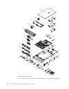
Server components .
.
.
.
.
.
.
.
.
.
. 27
System-board internal connectors .
.
.
.
. 29
System-board external connectors .
.
.
.
. 29
System-board switches, jumpers, and buttons
30
System-board LEDs.
.
.
.
.
.
.
.
.
. 33
Riser-card adapter expansion slot connectors
33
Riser-card assembly LEDs
.
.
.
.
.
.
. 35
2.5-inch/3.5-inch simple-swap/hot-swap hard
disk drive backplate assemblies and
backplanes
.
.
.
.
.
.
.
.
.
.
.
. 36
Server power features .
.
.
.
.
.
.
.
.
. 40
Turning on the server .
.
.
.
.
.
.
.
. 40
Turning off the server .
.
.
.
.
.
.
.
. 40
Chapter 2. Configuration information
and instructions. . . . . . . . . . . 43
Updating the firmware
.
.
.
.
.
.
.
.
.
. 43
Configuring the server.
.
.
.
.
.
.
.
.
.
. 44
Using the ServerGuide Setup and Installation CD 46
ServerGuide features .
.
.
.
.
.
.
.
. 47
Setup and configuration overview .
.
.
.
. 47
Typical operating-system installation .
.
.
. 47
Installing your operating system without
using ServerGuide .
.
.
.
.
.
.
.
.
. 48
Using the Setup utility.
.
.
.
.
.
.
.
.
. 48
Starting the Setup utility .
.
.
.
.
.
.
. 48
Setup utility menu choices .
.
.
.
.
.
. 49
Passwords .
.
.
.
.
.
.
.
.
.
.
.
. 53
Using the Boot Manager .
.
.
.
.
.
.
.
. 55
Starting the backup server firmware .
.
.
.
. 55
The UpdateXpress System Pack Installer .
.
.
. 56
Using the integrated management module .
.
. 56
Using the remote presence and blue-screen
capture features .
.
.
.
.
.
.
.
.
.
.
. 57
Obtaining the IMM host name .
.
.
.
.
. 58
Obtaining the IP address for the IMM
.
.
. 58
Logging on to the web interface
.
.
.
.
. 59
Using the embedded hypervisor
.
.
.
.
.
. 60
Configuring the Ethernet controller
.
.
.
.
. 61
Enabling Features on Demand Ethernet software
61
Enabling Features on Demand RAID software .
. 61
Configuring RAID arrays .
.
.
.
.
.
.
.
. 61
IBM Advanced Settings Utility program .
.
.
. 62
Updating IBM Systems Director
.
.
.
.
.
. 62
Installing a newer version
.
.
.
.
.
.
. 63
Installing updates with your management
server is connected to the Internet .
.
.
.
. 63
Installing updates with your management
server is not connected to the Internet
.
.
. 63
Updating the Universal Unique Identifier (UUID) 64
Updating the DMI/SMBIOS data .
.
.
.
.
. 66
Chapter 3. Troubleshooting . . . . . . 71
Start here .
.
.
.
.
.
.
.
.
.
.
.
.
.
. 71
Diagnosing a problem .
.
.
.
.
.
.
.
.
. 71
Undocumented problems .
.
.
.
.
.
.
.
. 73
Service bulletins .
.
.
.
.
.
.
.
.
.
.
.
. 74
Checkout procedure
.
.
.
.
.
.
.
.
.
.
. 74
About the checkout procedure .
.
.
.
.
.
. 74
Performing the checkout procedure .
.
.
.
. 75
Diagnostic tools .
.
.
.
.
.
.
.
.
.
.
.
. 76
Power-supply LEDs
.
.
.
.
.
.
.
.
.
. 78
AC power-supply LEDs .
.
.
.
.
.
.
. 78
System pulse LEDs .
.
.
.
.
.
.
.
.
.
. 80
PCI riser-card LEDs
.
.
.
.
.
.
.
.
.
. 80
Event logs .
.
.
.
.
.
.
.
.
.
.
.
.
. 81
Viewing event logs through the Setup utility
82
Viewing event logs without restarting the
server .
.
.
.
.
.
.
.
.
.
.
.
.
. 82
Clearing the event logs
.
.
.
.
.
.
.
. 83
POST
.
.
.
.
.
.
.
.
.
.
.
.
.
.
. 84
IBM Dynamic System Analysis .
.
.
.
.
.
. 84
DSA editions .
.
.
.
.
.
.
.
.
.
.
. 85
Running the DSA Preboot diagnostic
programs .
.
.
.
.
.
.
.
.
.
.
.
. 86
Diagnostic text messages .
.
.
.
.
.
.
. 87
Viewing the test log results and transferring
the DSA collection .
.
.
.
.
.
.
.
.
. 87
Automated service request (call home) .
.
.
.
. 87
IBM Electronic Service Agent
.
.
.
.
.
.
. 88
Error messages .
.
.
.
.
.
.
.
.
.
.
.
. 88
Troubleshooting by symptom
.
.
.
.
.
.
.
. 88
CD/DVD drive problems.
.
.
.
.
.
.
.
. 89
General problems .
.
.
.
.
.
.
.
.
.
. 90
Hard disk drive problems
.
.
.
.
.
.
.
. 90
Hypervisor problems .
.
.
.
.
.
.
.
.
. 92
Intermittent problems .
.
.
.
.
.
.
.
.
. 93
Keyboard, mouse, or USB-device problems .
.
. 93
Memory problems .
.
.
.
.
.
.
.
.
.
. 94
Microprocessor problems .
.
.
.
.
.
.
.
. 96
Monitor and video problems
.
.
.
.
.
.
. 97
© Copyright IBM Corp. 2014
iii
Summary of System x3650 M5
Page 1
System x3650 m5 type 5462 installation and service guide.
Page 3
System x3650 m5 type 5462 installation and service guide.
Page 4
Note before using this information and the product it supports, read the general information in appendix d, “getting help and technical assistance,” on page 973, “notices” on page 977, the warranty information document, and the safety information and environmental notices and user guide documents on...
Page 5: Contents
Contents safety . . . . . . . . . . . . . . . Vii safety statements . . . . . . . . . . . . Ix chapter 1. The system x3650 m5 server 1 the ibm documentation cd . . . . . . . . . 5 hardware and software requirements . . . . . 5 the ibm documentation cd . . . . . . . . 5 related documentation . . . . ...
Page 6
Network connection problems . . . . . . . 99 optional-device problems . . . . . . . . 99 power problems . . . . . . . . . . . 100 serial-device problems . . . . . . . . . 109 serverguide problems . . . . . . . . . 109 software problems. . . . . . . . . . . 110 universal serial bus (usb) port problem...
Page 7
Installing a 8x 2.5-inch simple-swap hdd serveraid assembly kit . . . . . . . . 286 installing a 8x 3.5-inch simple-swap hdd serveraid assembly kit . . . . . . . . 289 installing a 8x 2.5-inch hot-swap hdd assembly kit . . . . . . . . . . . . 291 installing a 8x 2.5-inch hot-swap hdd assembly with e...
Page 8
Vi system x3650 m5 type 5462: installation and service guide.
Page 9: Safety
Safety before installing this product, read the safety information. Antes de instalar este produto, leia as informações de segurança. Læs sikkerhedsforskrifterne, før du installerer dette produkt. Lees voordat u dit product installeert eerst de veiligheidsvoorschriften. Ennen kuin asennat tämän tuot...
Page 10
Les sikkerhetsinformasjonen (safety information) før du installerer dette produktet. Antes de instalar este produto, leia as informações sobre segurança. Antes de instalar este producto, lea la información de seguridad. Läs säkerhetsinformationen innan du installerar den här produkten. Viii system x...
Page 11
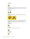
Safety statements these statements provide the caution and danger information that is used in this documentation. Important: each caution and danger statement in this documentation is labeled with a number. This number is used to cross reference an english-language caution or danger statement with t...
Page 12
Statement 2 caution: when replacing the lithium battery, use only ibm ® part number 33f8354 or an equivalent type battery recommended by the manufacturer. If your system has a module containing a lithium battery, replace it only with the same module type made by the same manufacturer. The battery co...
Page 13
Danger some laser products contain an embedded class 3a or class 3b laser diode. Note the following. Laser radiation when open. Do not stare into the beam, do not view directly with optical instruments, and avoid direct exposure to the beam. Statement 4 caution: use safe practices when lifting. ≥ 18...
Page 14
Statement 6 caution: if you install a strain-relief bracket option over the end of the power cord that is connected to the device, you must connect the other end of the power cord to an easily accessible power source. Statement 8 caution: never remove the cover on a power supply or any part that has...
Page 15
Caution: do not place any object on top of rack-mounted devices. Statement 27 caution: hazardous moving parts are nearby. Rack safety information, statement 2 danger v always lower the leveling pads on the rack cabinet. V always install stabilizer brackets on the rack cabinet. V always install serve...
Page 16
Xiv system x3650 m5 type 5462: installation and service guide.
Page 17
Chapter 1. The system x3650 m5 server this installation and service guide contains information and instructions for setting up your system x3650 m5 type 5462 server, instructions for installing some optional devices, cabling and configuring the server, removing and replacing devices, and diagnostics...
Page 18
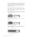
In terms of hot-swap configurations, the server comes with either eight 3.5-inch sas/sata or eight 2.5-inch sas/sata hot-swap hard disk drive bays. Most models contain a serveraid sas controller. The 2.5-inch models are capable of expansion to twenty-four 2.5-inch sas/sata hot-swap hard disk drive b...
Page 19
You can purchase an optional kit to install the eight additional 2.5-inch hard disk drive bays to a 24-drive-capable model. The following illustration shows a server with twenty-four 2.5-inch hot-swap hard disk drive bays. The following illustration shows a server with eight 3.5-inch simple-swap har...
Page 20
If firmware and documentation updates are available, you can download them from the ibm website. The server might have features that are not described in the documentation that comes with the server, and the documentation might be updated occasionally to include information about those features, or ...
Page 21
You can download an ibm serverguide setup and installation cd to help you configure the hardware, install device drivers, and install the operating system. For a list of supported optional devices for the server, see http://www.Ibm.Com/ systems/info/x86servers/serverproven/compat/us/. See the rack i...
Page 22
Where e is the drive letter of the cd or dvd drive, and click ok. – if you are using red hat linux, insert the cd into the cd or dvd drive; then, run the following command from the /mnt/cdrom directory: sh runlinux.Sh select the server from the product menu. The available topics list displays all th...
Page 23
That appears in the documentation has a number that you can use to locate the corresponding statement in your language in the safety information document. V safety information labels this document provides the simplified chinese, mongolian, tibetan, uygur, and zhuang translated versions of the produ...
Page 24
Server features and specifications the following information is a summary of the features and specifications of the server. Depending on the model, some features might not be available, or some specifications might not apply. Microprocessor (depending on the model): v supports up to two intel xeon ™...
Page 25
– supports up to eight 3.5-inch simple-swap sas/sata hard disk drive bays. – supports up to fourteen 3.5-inch hot-swap and two 2.5-inch hot-swap sas/sata hard disk drive bays. Attention: as a general consideration, do not mix standard 512-byte and advanced 4-kb format drives in the same raid array b...
Page 26
V type 2 – slot 1: pci express 3.0 x8 (full-height, full-length) – slot 2: pci express 3.0 x8 (full-height, full-length) – slot 3: ml2 v type 3 – slot 1: pci express 3.0 x16 (full-height, full-length) – slot 2: not available – slot 3: pci express 3.0 x8 (full-height, half-length) v type 4 – slot 1: ...
Page 27
Reflections and other nearby noise sources. The noise emission level stated in the declared (upper limit) sound-power level, in bels, for a random sample of system. Hot-swap fans: v one microprocessor: 4 dual-motor hot-swap fans v two microprocessors: 6 dual-motor hot-swap fans power supply: v up to...
Page 28
V relative humidity: 5% - 80% v maximum dew point: 29°c (84.2°f) shipment (non-operating): v temperature: -40°c to 60°c (-40°f - 140°f) v altitude: 10,700 m (35,105 ft) v relative humidity: 5% - 100% v maximum dew point: 29°c (84.2°f) attention: v design to ashrae class a3, ambient of 40°c, with rel...
Page 29
What your server offers this section introduces features and technologies the server uses and provides. V active energy manager the ibm active energy manager solution is an ibm systems director plug-in that measures and reports server power consumption as it occurs. This enables you to monitor power...
Page 30
The problem. Optionally, the imm also provides a virtual presence capability for remote server management capabilities. The imm provides remote server management through the following industry-standard interfaces: – intelligent platform management interface (ipmi) version 2.0 – simple network manage...
Page 31
The server has two pci interface risers. See “replacing an adapter” on page 190 for detailed information. V sd adapter a raid controller for secure digital (sd) media. It has two upstream connections, a usb connection to the server chipset, and an mmc connection to the integrated management module 2...
Page 32
V vmware esxi embedded hypervisor an optional usb flash device with vmware esxi embedded hypervisor software is available for purchase. Hypervisor is virtualization software that enables multiple operating systems to run on a host system at the same time. The usb embedded hypervisor flash device can...
Page 33
Information center at http://pic.Dhe.Ibm.Com/infocenter/director/pubs/ index.Jsp?Topic=%2fcom.Ibm.Director.Main.Helps.Doc%2ffqm0_main.Html, and the systems management website at http://www.Ibm.Com/systems/management/, which presents an overview of ibm systems management and ibm systems director. Rel...
Page 34
V power management: compliance with advanced configuration and power interface (acpi) v power-on self-test (post) v predictive failure analysis (pfa) alerts on memory, microprocessors, sas/sata hard disk drives or solid state drives, fans, power supplies, and vrm v redundant ethernet capabilities wi...
Page 35
Front view the following illustrations show the controls, leds, and connectors on the front of your server model. 2.5-inch hard disk drive server model. V 8 hard-disk drive configuration / 16 hard-disk drive configuration front view v 24 hard-disk drive configuration front view 3.5-inch hard disk dr...
Page 36
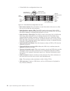
V 12 hard-disk drive configuration front view v rack release latches: press the latches on each front side of the server to slide the server out from the rack enclosure. V hard disk drive activity leds: this led is used on hot-swap sas or sata hard disk drives. Each hot-swap hard disk drive has an a...
Page 37
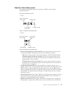
Operator information panel the following illustration shows the controls and leds on the operator information panel. Operator information panel v type 1 v type 2 v power-control button and power-on led: press this button to turn the server on and off manually. The states of the power-on led are as f...
Page 38
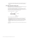
The lcd system information display panel, the operator information panel or on the system board is also lit to help isolate the error. This led is controlled by the imm. Lcd system information display panel use this information for an overview of the lcd system information display panel, which displ...
Page 39
The following is an example of the information that you will see on the display panel. This example shows the layout of the information in the main menu when the debug feature is enabled. When you navigate through the hierarchy of the menu options on the lcd system information display panel, the dis...
Page 40
To move within the menu options, use the scroll up or scroll down buttons, then the select button to enter a submenu set. The lcd system information display panel displays the following types of information about the server: v imm system error log (sel) note: the scroll down button will only functio...
Page 41
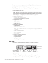
Might have to use a pen or the end of a straightened paper clip to press the button. The nmi button is in the lower left-hand corner on the rear of the server. V power connector: connect the power cord to this connector. Note: power supply 1 is the default/primary power supply. If power supply 1 fai...
Page 42
V ac power led: each hot-swap ac power supply has an ac power led. When the ac power led is lit, it indicates that sufficient power is coming into the power supply through the power cord. During typical operation, the ac power led is lit. For any other combination of leds, see “ac power-supply leds”...
Page 43
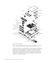
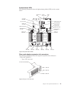
Server components the following illustration shows the major components in the server. The illustrations in this document might differ slightly from your hardware. Slot 1 slot 2 slot 3 slot 4 slot 5 3.5-inch rear two hard-disk-drive kit figure 22. Pci riser-card adapter expansion slot locations slot...
Page 44
Blue on a component indicates touch points, where you can grip the component to remove it from or install it in the server, open or close a latch, and so on. Orange on a component or an orange label on or near a component indicates that the component can be hot-swapped, which means that if the serve...
Page 45
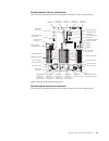
System-board internal connectors the following illustration shows the internal connectors on the system board. System-board external connectors the following illustration shows the external connectors on the system board. Dedicated slotless raid connector optical disk drive connector operator inform...
Page 46
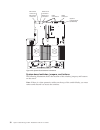
System-board switches, jumpers, and buttons the following illustration shows the location of the switches, jumpers, and buttons on the server. Note: if there is a clear protective sticker on the top of the switch blocks, you must remove and discard it to access the switches. System management (dedic...
Page 47
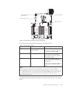
The following table describes the jumpers on the system board. Table 1. System board jumpers jumper number jumper name jumper setting j7 system tpm physical presence jumper v pins 1 and 2: normal (default). V pins 2 and 3: indicates a physical presence to the system tpm. J11 cmos clear jumper v pins...
Page 48
Table 2. System board sw6 switch block definition switch number default position description 1 off reserved. 2 off power-on password override. Changing the position of this switch bypasses the power-on password check the next time the server is turned on and starts the setup utility so that you can ...
Page 49
System-board leds the following illustration shows the light-emitting diodes (leds) on the system board. Riser-card adapter expansion slot connectors the following illustration shows the respective expansion slot connectors. V riser-card assembly 1 – type 1 pci riser card system error led locator bu...
Page 50
– type 2 pci riser card – type 3 pci riser card – type 4 pci riser card v riser-card assembly 2 – type 5 pci riser card pci riser-card assembly slot 1, pcie x8 slot 3, ml2 slot 2, pcie x8 figure 30. Type 2 pci riser card pci riser-card assembly slot 1, pcie x16 slot 3, pcie x8 figure 31. Type 3 pci ...
Page 51
– type 6 pci riser card riser-card assembly leds the following illustration shows the light-emitting diodes (leds) on the pci riser-card assembly. Note: error leds remain lit only while the server is connected to power. Pci riser-card assembly slot 6, pcie x8 slot 8, pcie x8 slot 7, pcie x8 figure 3...
Page 52
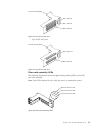
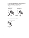
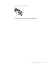
2.5-inch/3.5-inch simple-swap/hot-swap hard disk drive backplate assemblies and backplanes the following illustration shows the respective 2.5-inch/3.5-inch simple-swap/hot-swap hard disk drive backplate assemblies and backplanes. V 2.5-inch simple-swap hard disk drive backplate assembly – type 1 v ...
Page 53
V 3.5-inch simple-swap hard disk drive backplate assembly – type 4 2.5-inch hdd hot-swap backplane (expander) figure 38. Type 3 chapter 1. The system x3650 m5 server 37.
Page 54
V 3.5-inch hot-swap hard disk drive backplanes – type 5 3.5-inch hdd simple-swap backplate (ipass connector) 3.5-inch hdd simple-swap backplate for raid card (mini-sas hd connector) figure 39. Type 4 38 system x3650 m5 type 5462: installation and service guide.
Page 55
– type 6 3.5-inch hdd hot-swap backplane with 8hdds figure 40. Type 5 3.5-inch hdd hot-swap backplane with 12hdds figure 41. Type 6 chapter 1. The system x3650 m5 server 39.
Page 56
Server power features when the server is connected to an ac power source but is not turned on, the operating system does not run, and all core logic except for the integrated management module ii (imm2) is shut down. However, the server can respond to requests from imm2, such as a remote request to ...
Page 57
Statement 5 caution: the power control button on the device and the power switch on the power supply do not turn off the electrical current supplied to the device. The device also might have more than one power cord. To remove all electrical current from the device, ensure that all power cords are d...
Page 58
42 system x3650 m5 type 5462: installation and service guide.
Page 59
Chapter 2. Configuration information and instructions this chapter provides information about updating the firmware and using the configuration utilities. Updating the firmware use this information to update the firmware. Important: 1. Some cluster solutions require specific code levels or coordinat...
Page 60
When you replace a device in the server, you might have to update the firmware that is stored in memory on the device or restore the pre-existing firmware from a cd or dvd image. The following list indicates where the firmware is stored: v uefi firmware is stored in rom on the system board. V imm2 f...
Page 61
V vmware esxi embedded hypervisor an optional usb flash device with vmware esxi embedded hypervisor software is available for purchase. Hypervisor is virtualization software that enables multiple operating systems to run on a host system at the same time. The usb embedded hypervisor flash device can...
Page 62
Table 4. Server configuration and applications for configuring and managing raid arrays server configuration raid array configuration (before operating system is installed) raid array management (after operating system is installed) serveraid-m5110 adapter megaraid bios configuration utility (press ...
Page 63
Serverguide features this information provides an overview of the serverguide features. Features and functions can vary slightly with different versions of the serverguide program. To learn more about the version that you have, start the serverguide setup and installation cd and view the online over...
Page 64
3. The serverguide program presents operating-system partition options that are based on your operating-system selection and the installed hard disk drives. 4. The serverguide program prompts you to insert your operating-system cd and restart the server. At this point, the installation program for t...
Page 65
Setup utility menu choices use the setup utility main menu to view and configure server configuration data and settings. The following choices are on the setup utility main menu for the uefi. Depending on the version of the firmware, some menu choices might differ slightly from these descriptions. V...
Page 66
Select this choice to force int video support, if the operating system does not support uefi video output standards. - rehook int 19h select this choice to enable or disable devices from taking control of the boot process. The default is disable. - legacy thunk support select this choice to enable o...
Page 67
V reboot system on nmi select this choice to enable or disable restarting the system whenever a nonmaskable interrupt (nmi) occurs. Enable is the default. V halt on severe error select this choice to enable or disable the system from booting into os, displaying the post event viewer whenever a sever...
Page 68
Select this choice to enter the post event viewer to view the post error messages. – system event log select this choice to view the system event log. – clear system event log select this choice to clear the system event log. V user security select this choice to set, change, or clear passwords. See...
Page 69
Passwords from the user security menu choice, you can set, change, and delete a power-on password and an administrator password. The user security choice is on the full setup utility menu only. If you set only a power-on password, you must type the power-on password to complete the system startup an...
Page 70
Attention: before you change any switch settings or move any jumpers, turn off the server; then, disconnect all power cords and external cables. See the safety information that begins “safety” on page vii. Do not change settings or move jumpers on any system-board switch or jumper blocks that are no...
Page 71
Administrator password: if an administrator password is set, you must type the administrator password for access to the full setup utility menu. You can use any combination of 6 to 20 printable ascii characters for the password. Attention: if you set an administrator password and then forget it, the...
Page 72
The updatexpress system pack installer the updatexpress system pack installer detects supported and installed device drivers and firmware in the server and installs available updates. For additional information and to download the updatexpress system pack installer, go to the toolscenter for system ...
Page 73
V power/reset control (power-on, hard and soft shutdown, hard and soft reset, schedule power control). V query power-supply input power. V rom-based imm firmware flash updates. V serial over lan (sol). V serial port redirection over telnet or ssh. V smi handling v system event log (sel) - user reada...
Page 74
Obtaining the imm host name use this information to obtain the imm host name. About this task if you are logging on to the imm for the first time after installation, the imm defaults to dhcp. If a dhcp server is not available, the imm uses a static ip address of 192.168.70.125. The default ipv4 host...
Page 75
4. On the next screen, select integrated management module. 5. On the next screen, select network configuration. 6. Find the ip address and write it down. 7. Exit from the setup utility. Logging on to the web interface use this information to log on to the web interface. About this task to log on to...
Page 76
Using the embedded hypervisor the vmware esxi embedded hypervisor software is available on the optional ibm usb flash device with embedded hypervisor. About this task the usb flash device can be installed in usb connectors on the system board (see “system-board internal connectors” on page 29 for th...
Page 77
Configuring the ethernet controller use this information to configure the ethernet controller. The ethernet controllers are integrated on the system board. They provide an interface for connecting to a 10 mbps, 100 mbps, or 1 gbps network and provide full-duplex (fdx) capability, which enables simul...
Page 78
2. When prompted, is displayed, press f1. If you have set an administrator password, you must type the administrator password to access the full setup utility menu. If you do not type the administrator password, a limited setup utility menu is available. 3. Select system settings > storage. 4. Press...
Page 79
Installing a newer version about this task to locate and install a newer version of ibm systems director, complete the following steps: procedure 1. Check for the latest version of ibm systems director: a. Go to http://www.Ibm.Com/systems/management/director/ downloads.Html. B. If a newer version of...
Page 80
11. Select the updates that you want to install, and click install to start the installation wizard. Updating the universal unique identifier (uuid) use this information to update the universal unique identifier (uuid). About this task the universal unique identifier (uuid) must be updated when the ...
Page 81
V online authenticated lan access, type the command: [host ] [user ][password ] where: imm_internal_ip the imm internal lan/usb ip address. The default value is 169.254.95.118. Imm_user_id the imm account (1 of 12 accounts). The default value is userid. Imm_password the imm account password (1 of 12...
Page 82
Where: imm_external_ip the external imm lan ip address. There is no default value. This parameter is required. Imm_user_id the imm account (1 of 12 accounts). The default value is userid. Imm_password the imm account password (1 of 12 accounts). The default value is passw0rd (with a zero 0 not an o)...
Page 83
V online from the target system (lan or keyboard console style (kcs) access) v remote access to the target system (lan based) v bootable media containing asu (lan or kcs, depending upon the bootable media) 3. Copy and unpack the asu package, which also includes other required files, to the server. M...
Page 84
Examples that do not use the userid and password default values: asu set system_prod_data.Sysinfoprodname --user --password asu set system_prod_data.Sysinfoserialnum --user --password asu set system_prod_data.Sysencloseassettag --user --password examples that do use the userid and password default v...
Page 85
Imm_password the imm account password (1 of 12 accounts). The default value is passw0rd (with a zero 0 not an o). The following commands are examples of using the userid and password default values and not using the default values: examples that do not use the userid and password default values: asu...
Page 86
70 system x3650 m5 type 5462: installation and service guide.
Page 87: Chapter 3. Troubleshooting
Chapter 3. Troubleshooting this chapter describes the diagnostic tools and troubleshooting information that are available to help you solve problems that might occur in the server. If you cannot diagnose and correct a problem by using the information in this chapter, see appendix d, “getting help an...
Page 88
To download the latest version of dsa code and the dynamic system analysis installation and user's guide, go to http://www.Ibm.Com/support/entry/portal/ docdisplay?Lndocid=serv-dsa. 4. Check for and apply code updates. Fixes or workarounds for many problems might be available in updated uefi firmwar...
Page 89
Must remove nonsupported hardware before you contact ibm or an approved warranty service provider for support. B. Make sure that the server, operating system, and software are installed and configured correctly. Many configuration problems are caused by loose power or signal cables or incorrectly se...
Page 90
Service bulletins ibm continually updates the support website with the latest tips and techniques that you can use to solve problem that you might have with the system x3650 m5 server. To find service bulletins that are available for the ibm system x3650 m5 server, go to http://www.Ibm.Com/supportpo...
Page 91
V for information about power-supply problems, see “solving power problems” on page 111, “power problems” on page 100, and “power-supply leds” on page 78. V for intermittent problems, check the event log; see “event logs” on page 81 and appendix c, “dsa diagnostic test results,” on page 837. Perform...
Page 92
Diagnostic tools the section introduces available tools to help you diagnose and solve hardware-related problems. V lcd system information display panel use lcd system information display panel to diagnose system errors quickly. V event logs the event logs list the error codes and messages that are ...
Page 93
- service processor (integrated management module) status and configuration - system configuration - vital product data, firmware, and uefi configuration dsa portable creates a dsa log, which is a chronologically ordered merge of the system-event log (as the ipmi event log), the integrated managemen...
Page 94
11. Intel gpu 12. Nvidia gpu see “running the dsa preboot diagnostic programs” on page 86 for more information on running the dsa preboot program on the server. V troubleshooting by symptom these tables list problem symptoms and actions to correct the problems. See “troubleshooting by symptom” on pa...
Page 95
Ac power-supply leds description action notes ac dc error (!) off off off no ac power to the server or a problem with the ac power source. 1. Check the ac power to the server. 2. Make sure that the power cord is connected to a functioning power source. 3. Restart the server. If the error remains, ch...
Page 96
System pulse leds the following leds are on the system board and monitor the system power-on and power-off sequencing and boot progress (see “system-board leds” on page 33 for the location of these leds). Table 5. System pulse leds led description action imm2 heartbeat imm2 heartbeat boot process. T...
Page 97
Event logs error codes and messages displayed in post event log, system-event log, integrated management module (imm2) event log, and dsa event log. V post event log: this log contains the most recent error codes and messages that were generated during post. You can view the contents of the post eve...
Page 98
Viewing event logs through the setup utility to view the post event log or system-event log, complete the following steps: procedure 1. Turn on the server. 2. When the prompt setup is displayed, press f1. If you have set both a power-on password and an administrator password, you must type the admin...
Page 99
Table 6. Methods for viewing event logs (continued) condition action the server is not hung and is not connected to a network (using an operating system controlled network ports). V run dsa portable to view the diagnostic event log (requires ipmi driver) or create an output file that you can send to...
Page 100
Post when you turn on the server, it performs a series of tests to check the operation of the server components and some optional devices in the server. This series of tests is called the power-on self-test, or post. Note: this server does not use beep codes for server status. If a power-on password...
Page 101
Dsa editions two editions of dynamic system analysis are available. V dsa portable dsa portable edition runs within the operating system; you do not have to restart the server to run it. It is packaged as a self-extracting file that you download from the web. When you run the file, it self-extracts ...
Page 102
Running the dsa preboot diagnostic programs use this information to run the dsa preboot diagnostic programs. About this task note: the dsa memory test might take up to 30 minutes to run. If the problem is not a memory problem, skip the memory test. To run the dsa preboot diagnostic programs, complet...
Page 103
Diagnostic text messages diagnostic text messages are displayed while the tests are running. A diagnostic text message contains one of the following results: passed: the test was completed without any errors. Failed: the test detected an error. Aborted: the test could not proceed because of the serv...
Page 104
Ibm electronic service agent ibm electronic service agent monitors, tracks, and captures system hardware errors and hardware and software inventory information, and reports serviceable problems directly to ibm support. You can also choose to collect data manually. It uses minimal system resources, a...
Page 105
Cd/dvd drive problems use the troubleshooting tables to find solutions to problems that have identifiable symptoms. V follow the suggested actions in the order in which they are listed in the action column until the problem is solved. V if an action step is preceded by “(trained technician only),” t...
Page 106
General problems use the troubleshooting tables to find solutions to problems that have identifiable symptoms. V follow the suggested actions in the order in which they are listed in the action column until the problem is solved. V if an action step is preceded by “(trained technician only),” that s...
Page 107
V follow the suggested actions in the order in which they are listed in the action column until the problem is solved. V if an action step is preceded by “(trained technician only),” that step must be performed only by a trained technician. V go to the ibm support website at http://www.Ibm.Com/suppo...
Page 108
V follow the suggested actions in the order in which they are listed in the action column until the problem is solved. V if an action step is preceded by “(trained technician only),” that step must be performed only by a trained technician. V go to the ibm support website at http://www.Ibm.Com/suppo...
Page 109
Intermittent problems use the troubleshooting tables to find solutions to problems that have identifiable symptoms. V follow the suggested actions in the order in which they are listed in the action column until the problem is solved. V if an action step is preceded by “(trained technician only),” t...
Page 110
V follow the suggested actions in the order in which they are listed in the action column until the problem is solved. V if an action step is preceded by “(trained technician only),” that step must be performed only by a trained technician. V go to the ibm support website at http://www.Ibm.Com/suppo...
Page 111
V follow the suggested actions in the order in which they are listed in the action column until the problem is solved. V if an action step is preceded by “(trained technician only),” that step must be performed only by a trained technician. V go to the ibm support website at http://www.Ibm.Com/suppo...
Page 112
V follow the suggested actions in the order in which they are listed in the action column until the problem is solved. V if an action step is preceded by “(trained technician only),” that step must be performed only by a trained technician. V go to the ibm support website at http://www.Ibm.Com/suppo...
Page 113
Monitor and video problems some ibm monitors have their own self-tests. If you suspect a problem with your monitor, see the documentation that comes with the monitor for instructions for testing and adjusting the monitor. If you cannot diagnose the problem, call for service. V follow the suggested a...
Page 114
V follow the suggested actions in the order in which they are listed in the action column until the problem is solved. V if an action step is preceded by “(trained technician only),” that step must be performed only by a trained technician. V go to the ibm support website at http://www.Ibm.Com/suppo...
Page 115
Network connection problems use the troubleshooting tables to find solutions to problems that have identifiable symptoms. V follow the suggested actions in the order in which they are listed in the action column until the problem is solved. V if an action step is preceded by “(trained technician onl...
Page 116
V follow the suggested actions in the order in which they are listed in the action column until the problem is solved. V if an action step is preceded by “(trained technician only),” that step must be performed only by a trained technician. V go to the ibm support website at http://www.Ibm.Com/suppo...
Page 117
V follow the suggested actions in the order in which they are listed in the action column until the problem is solved. V if an action step is preceded by “(trained technician only),” that step must be performed only by a trained technician. V go to the ibm support website at http://www.Ibm.Com/suppo...
Page 118
V follow the suggested actions in the order in which they are listed in the action column until the problem is solved. V if an action step is preceded by “(trained technician only),” that step must be performed only by a trained technician. V go to the ibm support website at http://www.Ibm.Com/suppo...
Page 119
V follow the suggested actions in the order in which they are listed in the action column until the problem is solved. V if an action step is preceded by “(trained technician only),” that step must be performed only by a trained technician. V go to the ibm support website at http://www.Ibm.Com/suppo...
Page 120
V follow the suggested actions in the order in which they are listed in the action column until the problem is solved. V if an action step is preceded by “(trained technician only),” that step must be performed only by a trained technician. V go to the ibm support website at http://www.Ibm.Com/suppo...
Page 121
V follow the suggested actions in the order in which they are listed in the action column until the problem is solved. V if an action step is preceded by “(trained technician only),” that step must be performed only by a trained technician. V go to the ibm support website at http://www.Ibm.Com/suppo...
Page 122
V follow the suggested actions in the order in which they are listed in the action column until the problem is solved. V if an action step is preceded by “(trained technician only),” that step must be performed only by a trained technician. V go to the ibm support website at http://www.Ibm.Com/suppo...
Page 123
V follow the suggested actions in the order in which they are listed in the action column until the problem is solved. V if an action step is preceded by “(trained technician only),” that step must be performed only by a trained technician. V go to the ibm support website at http://www.Ibm.Com/suppo...
Page 124
V follow the suggested actions in the order in which they are listed in the action column until the problem is solved. V if an action step is preceded by “(trained technician only),” that step must be performed only by a trained technician. V go to the ibm support website at http://www.Ibm.Com/suppo...
Page 125
Serial-device problems use the troubleshooting tables to find solutions to problems that have identifiable symptoms. V follow the suggested actions in the order in which they are listed in the action column until the problem is solved. V if an action step is preceded by “(trained technician only),” ...
Page 126
V follow the suggested actions in the order in which they are listed in the action column until the problem is solved. V if an action step is preceded by “(trained technician only),” that step must be performed only by a trained technician. V go to the ibm support website at http://www.Ibm.Com/suppo...
Page 127
Universal serial bus (usb) port problems use the troubleshooting tables to find solutions to problems that have identifiable symptoms. V follow the suggested actions in the order in which they are listed in the action column until the problem is solved. V if an action step is preceded by “(trained t...
Page 128
C. For other rail errors (pwr rail a error, see step 4b on page 111), remove each component that is associated with the faulty pwr rail, one at a time, in the sequence indicated in table 7, restarting the server each time, until the cause of the overcurrent condition is identified. Table 7. Componen...
Page 129
Table 7. Components associated with power rail errors (continued) pwr rail error in the imm event log components pwr rail h error v hard disk drives at backplane assembly 3 v hard disk drive backplane assembly 3 v pcie solid state drives v pcie solid state drive backplane assembly pwr rail i error v...
Page 130
Solving ethernet controller problems the method that you use to test the ethernet controller depends on which operating system you are using. See the operating-system documentation for information about ethernet controllers, and see the ethernet controller device-driver readme file. About this task ...
Page 131
Solving undetermined problems if dynamic system analysis (dsa) did not diagnose the failure or if the server is inoperative, use the information in this section. About this task if you suspect that a software problem is causing failures (continuous or intermittent), see “software problems” on page 1...
Page 132
Problem determination tips because of the variety of hardware and software combinations that can encounter, use the following information to assist you in problem determination. If possible, have this information available when requesting assistance from ibm. The model name and serial number are loc...
Page 133
V diagnostic program type and version level v configuration option settings v operating-system control-file setup see appendix d, “getting help and technical assistance,” on page 973 for information about calling ibm for service. Recovering the server firmware (uefi update failure) use this informat...
Page 134
5. Move the uefi boot backup jumper (j15) from pins 1 and 2 to pins 2 and 3 to enable the uefi recovery mode. 6. Reinstall the server cover; then, reconnect all power cords. 7. Restart the server. The system begins the power-on self-test (post). 8. Boot the server to an operating system that is supp...
Page 135
22. If these recovery efforts fail, contact your ibm service representative for support. Results in-band automated boot recovery method this section details the in-band automated boot recovery method. About this task note: use this method if the board led on the light path diagnostics panel is lit a...
Page 136
Nx-boot failure use this information for nx-boot failure. Configuration changes, such as added devices or adapter firmware updates, and firmware or application code problems can cause the server to fail post (the power-on self-test). If this occurs, the server responds in either of the following way...
Page 137
Chapter 4. Parts listing, system x3650 m5 type 5462 the parts listing of system x3650 m5 type 5462 the following replaceable components are available for the system x3650 m5 type 5462 server, except as specified otherwise in “replaceable server components.” for an updated parts listing, go to http:/...
Page 138
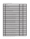
The following table lists the part numbers for the server replaceable components. 30 31 32 33 35 3 4 5 6 7 21 9 8 29 28 27 26 25 22 23 24 20 18 17 11 12 2 1 19 34 13 16 15 14 10 figure 47. Server components 122 system x3650 m5 type 5462: installation and service guide.
Page 139
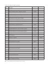
Table 8. Parts listing, type 5462 index description cru part number (tier 1) cru part number (tier 2) 1 2.5-inch rear two hard-disk-drive kit 00al953 2 3.5-inch rear two hard-disk-drive kit 00al954 3 pcie riser (2 x8 pcie + 1 x8 ml2 slots) 00fk630 3 pcie riser (1 x16 pcie + 1 x8 ml2 slots) 00fk631 3...
Page 140
Table 8. Parts listing, type 5462 (continued) index description cru part number (tier 1) cru part number (tier 2) 10 riser cage filler 00al950 11 right functional eia assembly 00fk801 12 right eia assembly 00kf411 13 left video eia assembly 00fk805 14 media cage 00al949 15 operator information panel...
Page 141
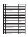
Table 8. Parts listing, type 5462 (continued) index description cru part number (tier 1) cru part number (tier 2) 23 self-encrypting drive, 3.5-inch hot-swap, 4 tb, sas, 7.2 k 00fn249 23 self-encrypting drive, 3.5-inch hot-swap, 6 tb, sas, 7.2 k 00fn259 24 3.5-inch filler panel 69y5364 25 3.5-inch h...
Page 142
Table 8. Parts listing, type 5462 (continued) index description cru part number (tier 1) cru part number (tier 2) broadcom netxtreme ii ml2 dual port 10gbe sfp+ 94y5231 broadcom netxtreme ii ml2 dual port 10gbaset 94y5233 emulex vfa5 ml2 dual port 10gbe sfp+ adapter 00ad918 intel ethernet dual port ...
Page 143
Table 8. Parts listing, type 5462 (continued) index description cru part number (tier 1) cru part number (tier 2) cable, 3.0m hd sas to msas 00d2148 cable, 6.0m hd sas to msas 44x3322 cable, front hdd 80 mm 00kc582 cable, front hdd 150 mm 00fk819 cable, front hdd 230 mm 00fk825 cable, front hdd 260 ...
Page 144
Table 8. Parts listing, type 5462 (continued) index description cru part number (tier 1) cru part number (tier 2) nvidia grid k2 (actively cooled) 90y2395 nvidia tesla k40c 90y2408 security bezel 00fk615 misc kit 00kf419 slide kit 00ka592 cable management arm (cma) 00ka594 label, chassis 00kf412 lab...
Page 145
Power cords for your safety, a power cord with a grounded attachment plug is provided to use with this product. To avoid electrical shock, always use the power cord and plug with a properly grounded outlet. Ibm power cords used in the united states and canada are listed by underwriter's laboratories...
Page 146
Power cord part number used in these countries and regions 39m5151 abu dhabi, bahrain, botswana, brunei darussalam, channel islands, china (hong kong s.A.R.), cyprus, dominica, gambia, ghana, grenada, iraq, ireland, jordan, kenya, kuwait, liberia, malawi, malaysia, malta, myanmar (burma), nigeria, o...
Page 147
Chapter 5. Removing and replacing components use this information to remove and replace the server components. The types of replaceable components are: v structural parts: purchase and replacement of structural parts (components, such as chassis assembly, top cover, and bezel) is your responsibility...
Page 148
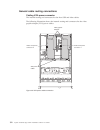
General cable routing connections cabling vga power connector the internal routing and connectors for the front usb and video cables. The following illustration shows the internal routing and connectors for the video graphic adapter (vga) power cables: video graphic adapters vga power cables video c...
Page 149
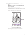
2.5-inch hard disk drive cable connection the following illustrations show the cabling information for the 2.5-inch drive models. Important: make sure all sas cables are routed lower than the dimm latches. 8x2.5-inch drive model the internal routing for the 8x2.5-inch drive model cables. The followi...
Page 150
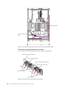
8x2.5-inch hot-swap hard disk drive model v 8x2.5-inch hot-swap hard disk drive sas signal cable power / configuration cable figure 50. 8x2.5-inch simple-swap hard disk drive with software raid cabling 2.5-inch hdd hot-swap backplane power / configuration cable sas signal cable sas 0 sas 1 figure 51...
Page 151
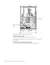
16x2.5-inch drive model the internal routing for the 16x2.5-inch drive model cables. The following illustration shows the internal routing for the 16x2.5-inch drive model cables. 16x2.5-inch simple-swap hard disk drive model v 16x2.5-inch simple-swap hard disk drive with hardware raid sas signal cab...
Page 152
16x2.5-inch hot-swap hard disk drive model v 16x2.5-inch hot-swap hard disk drive with 2 identical backplanes sas signal cables power / configuration cable figure 53. 16x2.5-inch simple-swap hard disk drive with hardware raid cabling 2.5-inch hdd hot-swap backplane power / configuration cable sas si...
Page 153
V 16x2.5-inch hot-swap hard disk drive with one expander sas signal cables power / configuration cables sas 0 sas 1 sas 0 sas 1 figure 55. 16x2.5-inch hot-swap hard disk drive cabling 2.5-inch hdd hot-swap backplane power / configuration cable sas signal cable power / configuration cable 2.5-inch hd...
Page 154
24x2.5-inch drive model the internal routing for the 24x2.5-inch drive model cables. The following illustration shows the internal routing for the 24x2.5-inch drive model cables. 24x2.5-inch hot-swap hard disk drive model v 24x2.5-inch hot-swap hard disk drive with 3 identical backplanes sas signal ...
Page 155
2.5-inch hdd hot-swap backplane power / configuration cable sas signal cable sas 0 sas 1 2.5-inch hdd hot-swap backplane power / configuration cable sas signal cable sas 0 sas 1 2.5-inch hdd hot-swap backplane power / configuration cable sas signal cable sas 0 sas 1 figure 58. 24x2.5-inch hot-swap h...
Page 156
V 24x2.5-inch hot-swap hard disk drive with one expander 2.5-inch hdd hot-swap backplane power / configuration cable sas signal cable power / configuration cable 2.5-inch hdd hot-swap backplane (expander) 2.5-inch hdd hot-swap backplane power / configuration cable sas signal cable sas signal cable f...
Page 157
V 24x2.5-inch hot-swap hard disk drive with two expanders 2.5-inch hdd hot-swap backplane power / configuration cable sas signal cable power / configuration cable 2.5-inch hdd hot-swap backplane (expander) power / configuration cable 2.5-inch hdd hot-swap backplane (expander) sas signal cable figure...
Page 158
3.5-inch hard disk drive cable connection the following illustrations show the cabling information for the 3.5-inch drive models. Important: make sure all sas cables are routed lower than the dimm latches. 8x3.5-inch drive model the internal routing for the 8x3.5-inch drive model cables. The followi...
Page 159
8x3.5-inch hot-swap hard disk drive model v 8x3.5-inch hot-swap hard disk drive sas signal cable power / configuration cable figure 65. 8x3.5-inch simple-swap hard disk drives with software raid cabling chapter 5. Removing and replacing components 143.
Page 160
12x3.5-inch drive model the internal routing for the 12x3.5-inch drive model cables. The following illustration shows the internal routing for the 12x3.5-inch drive model cables. 12x3.5-inch hot-swap hard disk drive model v 12x3.5-inch hot-swap hard disk drive sas signal cable power / configuration ...
Page 161
Removing and replacing server components this section provides information for removing and replacing components in the server. Removing and replacing structural parts replacement of structural parts is your responsibility. If ibm installs a structural part at your request, you will be charged for t...
Page 162
Removing the top cover use this information to remove the top cover. About this task to remove the top cover, complete the following steps: procedure 1. Read the safety information that begins on page “safety” on page vii and “installation guidelines” on page 283. 2. Turn off the server and peripher...
Page 163
Replacing the top cover use this information to replace the server top cover. About this task to replace the server top cover, complete the following steps: procedure 1. Make sure that all cables, adapters, and other components are installed and seated correctly and that you have not left loose tool...
Page 164
Removing and replacing tier 1 crus replacement of tier 1 crus is your responsibility. If ibm installs a tier 1 cru at your request, you will be charged for the installation. The illustrations in this document might differ slightly from your hardware. Removing the air baffle when you work with some o...
Page 165
7. If you are instructed to return the air baffle, follow all of the packaging instructions, and use any packaging materials for shipping that are supplied to you. Replacing the air baffle use this information to replace the air baffle. About this task to replace the air baffle, complete the followi...
Page 166
Removing the power paddle module use this information to remove the power paddle module. About this task to remove the power paddle module, complete the following steps: procedure 1. Read the safety information that begins on “safety” on page vii and “installation guidelines” on page 283. 2. Turn of...
Page 167
Replacing the power paddle module use this information to install the power paddle module. About this task to install the power paddle module, complete the following steps: procedure 1. Read the safety information that begins on “safety” on page vii and “installation guidelines” on page 283. 2. Turn...
Page 168
Removing the front usb assembly use this information to remove the front usb assembly. About this task to remove the front usb assembly, complete the following steps. Procedure 1. Read the safety information that begins on “safety” on page vii and “installation guidelines” on page 283. 2. Turn off t...
Page 169
5. Connect the cable on the front usb assembly to the system board. The following illustration shows the cable routing for the front usb assembly. Note: to connect the front usb assembly cable on the system board, press evenly on the cable. Pressing on one side of the cable might cause damage to the...
Page 170
7. Slide the server into the rack. 8. Reconnect the power cords and any cables that you removed. 9. Turn on the peripheral devices and the server. Removing a hot-swap hard disk drive use this information to remove a hot-swap hard disk drive. About this task attention: v to avoid damage to the hard d...
Page 171
4. Grasp the handle and slide the drive out of the drive bay. 5. Reinstall the drive bay filler panel. 6. If you are instructed to return the drive assembly, follow all packaging instructions, and use any packaging materials for shipping that are supplied to you. Replacing a hot-swap hard disk drive...
Page 172
Note: if you have only one hard disk drive, you must install it in the bay 0 (upper-left). Procedure 1. Read the safety information that begins on “safety” on page vii and “installation guidelines” on page 283. 2. Remove the filler panel from the empty drive bay. Keep the filler panel in a safe plac...
Page 173
Note: if the server is configured for raid operation using a serveraid adapter, you might have to reconfigure your disk arrays after you install hard disk drives. See the serveraid adapter documentation for additional information about raid operation and complete instructions for using the serveraid...
Page 174
4. Reinstall the drive bay filler panel that you removed earlier, if needed. 5. If you are instructed to return the drive assembly, follow all packaging instructions, and use any packaging materials for shipping that are supplied to you. Replacing a simple-swap hard disk drive use this information t...
Page 175
To install a simple-swap hard disk drive, complete the following steps: procedure 1. Read the safety information that begins on “safety” on page vii and “installation guidelines” on page 283. 2. Turn off the server and peripheral devices and disconnect the power cords and all external cables. 3. Rem...
Page 176
Removing the optical drive cable use this information to remove the optical drive cable. About this task to remove the optical cable, complete the following steps: procedure 1. Read the safety information that begins on “safety” on page vii and “installation guidelines” on page 283. 2. Turn off the ...
Page 177
7. If you are instructed to return the optical drive cable, follow all packaging instructions, and use any packaging materials for shipping that are supplied to you. Replacing the optical drive cable use this information to install the optical drive cable. About this task to install the optical driv...
Page 178
The following illustration shows cable routing for the optical cable: attention: follow the optical drive cable routing as the illustration shows. Make sure that the cable is not pinched and does not cover any connectors or obstruct any components on the system board. 6. Replace the fan cage assembl...
Page 179
Removing an optical drive use this information to remove an optical drive. About this task you can go to “front view” on page 19 to see the locations of an optical drive on the server. To remove an optical drive, complete the following steps: procedure 1. Read the safety information that begins on “...
Page 180
7. Slide the optical drive filler panel into the optical drive bay until the optical drive filler panel clicks into place. 8. If you are instructed to return the optical drive, follow all packaging instructions, and use any packaging materials for shipping that are supplied to you. Replacing an opti...
Page 181
Caution: when laser products (such as cd-roms, optical drives, fiber optic devices, or transmitters) are installed, note the following: v do not remove the covers. Removing the covers of the laser product could result in exposure to hazardous laser radiation. There are no serviceable parts inside th...
Page 182
10. Connect the optical drive cable (see “replacing the optical drive cable” on page 161). 11. Reconnect the power cords and any cables that you removed. 12. Turn on the peripheral devices and the server. Removing a memory module use this information to remove a memory module. About this task to rem...
Page 183
6. If you are instructed to return the dimm, follow all packaging instructions, and use any packaging materials for shipping that are supplied to you. Installing a memory module the following notes describe the types of dimms that the server supports and other information that you must consider when...
Page 184
12800 = 12.80 gbps (ddr4-1600 sdrams, 8-byte primary data bus) 14900 = 14.93 gbps (ddr4-1866 sdrams, 8-byte primary data bus) 17000 = 17.00 gbps (ddr4-2133 sdrams, 8-byte primary data bus) - m is the dimm type l = load reduction dimm (lrdimm) r = registered dimm (rdimm) - aa is the cas latency, in c...
Page 185
V the lrdimm option that is available for the server is 32 gb and 64 gb. The server supports a minimum of 32 gb and a maximum of 1536 gb of system memory using lrdimms. Note: the amount of usable memory is reduced depending on the system configuration. A certain amount of memory must be reserved for...
Page 186
Dimm installation sequence: depending on the server model, the server may come with a minimum of one 4 gb dimm installed in slot 1. When you install additional dimms, install them in the order shown in the following table to optimize system performance. In general, all four channels on the memory in...
Page 187
6. Touch the static-protective package that contains the dimm to any unpainted metal surface on the outside of the server. Then, remove the dimm from the package. 7. Turn the dimm so that the alignment slot align correctly with the alignment tab. 8. Insert the dimm into the connector by aligning the...
Page 188
Removing the fan cage assembly use this information to remove the fan cage assembly. About this task to replace some components or to create working room, you might have to remove the fan cage assembly. Note: to remove or install a fan, it is not necessary to remove the fan cage. See “removing a hot...
Page 189
Replacing the fan cage assembly use this information to replace the fan cage assembly. About this task to install the fan cage assembly, complete the following steps: procedure 1. Read the safety information that begins on “safety” on page vii and “installation guidelines” on page 283. 2. Turn off t...
Page 190
Removing a hot-swap fan use this information to remove a hot-swap fan. About this task attention: to ensure proper server operation, replace a failed hot-swap fan within 30 seconds. To remove a hot-swap-fan, complete the following steps: procedure 1. Read the safety information that begins on “safet...
Page 191
Replacing a hot-swap fan use this information to replace a hot-swap fan. About this task for proper cooling, the server requires that all four dual-motor hot-swap fans be installed at all times. Attention: to ensure proper operation, replace a failed hot-swap fan within 30 seconds. To replace a hot-...
Page 192
Removing the media cage use this information to remove the media cage. About this task to remove the media cage, complete the following steps: procedure 1. Read the safety information that begins on “safety” on page vii and “installation guidelines” on page 283. 2. Turn off the server and peripheral...
Page 193
5. Loosen the thumbscrew that is used to secure the media cage onto the server. 6. Carefully push the media cage out of the server and set it aside. 7. If you are instructed to return the media cage, follow all of the packaging instructions, and use any packaging materials for shipping that are supp...
Page 194
Replacing the media cage use this information to replace the media cage. About this task to install the media cage, complete the following steps: procedure 1. Read the safety information that begins on “safety” on page vii and “installation guidelines” on page 283. 2. Turn off the server and periphe...
Page 195
7. Replace the top cover (see “replacing the top cover” on page 147). 8. Slide the server into the rack. 9. Reconnect the power cords and any cables that you removed. 10. Turn on the peripheral devices and the server. Operator information / lcd panel cable dvd drive cable front usb cable figure 105....
Page 196
Removing a riser-card assembly use this information to remove a riser-card assembly. About this task see http://www.Ibm.Com/systems/info/x86servers/serverproven/compat/us/ for a list of riser-card assemblies that you can use with the server. To remove a riser-card assembly, complete the following st...
Page 197
5. If you are instructed to return the riser-card assembly, follow all of the packaging instructions, and use any packaging materials for shipping that are supplied to you. Replacing a riser-card assembly use this information to replace a riser-card assembly. About this task the server provides two ...
Page 198
4. Reinstall any adapters and reconnect any internal cables you might have removed in other procedures (see “replacing an adapter” on page 190 and “internal cable routing and connectors” on page 131). 5. Align the riser-card assembly with the selected pci connector on the system board and align it w...
Page 199
6. Replace the top cover (see “replacing the top cover” on page 147). 7. Slide the server into the rack. 8. Reconnect the power cords and any cables that you removed. 9. Turn on the peripheral devices and the server. Removing the dedicated slotless raid controller use this information to remove the ...
Page 200
5. ▌1▐press the retention tabs away from the controller; then, slightly lift up the rear of the controller, and ▌2▐pull it out of the connector on the system board. 6. If you are instructed to return the dedicated slotless raid controller, follow all of the packaging instructions, and use any packag...
Page 201
7. Route the backplane signal cables. (see “2.5-inch hard disk drive cable connection” on page 133 and “3.5-inch hard disk drive cable connection” on page 142). 8. Connect the signal cables to the controller. 9. Reconnect any cables that you removed. 10. Replace the top cover (see “replacing the top...
Page 202
The following table describes the maximal card dimension supported in each slot. Table 12. The maximal card dimension supported in each slot riser-card assembly slot number the maximal card dimension supported riser-card assembly 1 1 full height, up to full length 2 full height, up to full length 3 ...
Page 203
V if you are removing an adapter from pci expansion slot 1, 2, or 3, remove riser-card assembly 1. V if you are removing an adapter from pci expansion slot 6, 7 or 8, remove riser-card assembly 2. 5. Disconnect any cables from the adapter (make note of the cable routing, in case you reinstall the ad...
Page 204
Removing an adapter in pci expansion slot 4 or slot 5: use this information to remove an adapter in pci expansion slot 4 or slot 5. About this task to remove an adapter in pci expansion slot 4 or slot 5, complete the following steps: procedure 1. Read the safety information that begins on “safety” o...
Page 205
Removing an adapter in the rear two hard-disk-drive kit: use this information to remove an adapter in the rear two hard-disk-drive kit. About this task to remove an adapter in the rear two hard-disk-drive kit, complete the following steps: procedure 1. Read the safety information that begins on “saf...
Page 206
Replacing an adapter use this information to replace an adapter. Replacing an adapter in a riser-card assembly: use this section to replace an adapter in a riser-card assembly. About this task the following illustration shows the locations of the adapter expansion slots from the rear of the server. ...
Page 207
Table 13. The maximal card dimension supported in each slot (continued) riser-card assembly slot number the maximal card dimension supported riser-card assembly 2 6 full height, up to full length 7 full height, up to full length 8 full height, half length the following notes describe the types of ad...
Page 208
Table 15. Non-supported adapters in the slot 3 and the slot 8 (continued) adapter description option part number fru part number qlogic 8200 dual port 10gbe sfp+ adapter for ibm system x 90y4600 90y4605 broadcom netxtrme dual port 10gbe spg+ adapter for ibm system x 94y5180 94y5182 mellanox connectx...
Page 209
8. Rotate the retention latch to the close position. Note: fasten the screw on the retention latch to secure the adapter. 9. If you are installing a full-height, full-length adapter, insert the shipping brackets. 10. Connect any required cables to the adapter. Attention: v when you route cables, do ...
Page 210
V for full-height, full-length adapters note: shipping brackets are only included in the server that is pre-configured with full-height, full-length adapters pci riser-card assembly 2 pci riser-card assembly 1 figure 124. Riser-card assembly installation - half-length and low profile adapters 194 sy...
Page 211
12. Perform any configuration tasks that are required for the adapter. 13. Reinstall the top cover (see “replacing the top cover” on page 147). 14. Slide the server into the rack. 15. Reconnect the power cords and any cables that you removed. 16. Turn on the peripheral devices and the server. Replac...
Page 212
6. ▌2▐align the adapter with the pci connector on the system board and press the adapter firmly into the pci connector on the system board. 7. Rotate the retention bracket to the close position. 8. Connect any required cables to the adapter. Attention: v when you route cables, do not block any conne...
Page 213
Replacing an adapter in the rear two hard-disk-drive kit: use this information to replace an adapter in the rear two hard-disk-drive kit. About this task to install an adapter, complete the following steps: procedure 1. Read the safety information that begins on “safety” on page vii and “installatio...
Page 214
Removing a raid adapter battery/flash power module use this information to remove a raid adapter battery/flash power module. About this task if a raid adapter battery / flash power module is installed near the fan cage and you need to replace it, complete the following steps: procedure 1. Read the s...
Page 215
Replacing a raid adapter battery/flash power module use this information to replace a raid adapter battery/flash power module. About this task to install a raid adapter battery/flash power module in the server, complete the following steps: procedure 1. Read the safety information that begins on “sa...
Page 216
7. Connect the battery/flash power module cable to the raid adapter battery/flash power module connector. Attention: make sure that the cable is not pinched and does not cover any connectors or obstruct any components on the system board. 8. Reinstall the riser-card assemblies if you have remove the...
Page 217
V 2.5-inch rear two hard-disk-drive kit removal v 3.5-inch rear two hard-disk-drive kit removal 2.5-inch rear two hard-disk-drive kit 1 figure 131. 2.5-inch rear two hard-disk-drive kit removal 3.5-inch rear two hard-disk-drive kit figure 132. 3.5-inch rear two hard-disk-drive kit removal chapter 5....
Page 218
Replacing the rear two hard-disk-drive kit use this information to replace the rear two hard-disk-drive kit on the system board. About this task note: please refer to the following rules before you install the rear two hard-disk-drive kit. V 2.5-inch hot-swap hard disk drive model – supports one 2.5...
Page 219
V 3.5-inch rear two hard-disk-drive kit installation 5. Connect the mini-sas hd cable from the rear hard drive backplane to the raid card. V for 2.5-inch rear two hard-disk-drive kit v for 3.5-inch rear two hard-disk-drive kit, there are two possible cable routing configurations: – connect to the ra...
Page 220
– connect to the 3.5-inch hdd hot-swap backplane with 12 hdds from the rear hard drive backplane sas signal cable 3.5" hard disk drive cage raid adapter figure 136. 3.5-inch rear two hard-disk-drive kit cable routing 204 system x3650 m5 type 5462: installation and service guide.
Page 221
6. Press down the hdd kit firmly until the hdd kit is fully seated in the connector on the system board. 7. Replace the top cover (see “replacing the top cover” on page 147). 8. Slide the server into the rack. 9. Reconnect the power cords and any cables that you removed. 10. Turn on the peripheral d...
Page 222
Removing an eia assembly use the following instructions to remove an eia assembly for 2.5-inch and 3.5-inch models. 2.5-inch model: there are the right eia assembly and the left eia assembly on the server, use the following steps to remove them. For the right eia assembly 1. Read the safety informat...
Page 223
7. Tilt the cable cover and remove it from the server. 8. Grasp the eia assembly and pull it slightly forward to remove it from the server. Screws figure 139. Screw removal cable arm cover figure 140. Cable cover removal chapter 5. Removing and replacing components 207.
Page 224
9. Position the eia assembly as shown in the following illustration; then, remove the assembly out of the server. 10. If you are instructed to return the eia assembly, follow all packaging instructions, and use any packaging materials for shipping that are supplied to you. For the left eia assembly ...
Page 225
Note: disengage all latches, release tabs or locks on cable connectors when you disconnect all cables from the system board. Failing to release them before removing the cables will damage the cable sockets on the system board. The cable sockets on the system board are fragile. Any damage to the cabl...
Page 226
8. Grasp the eia assembly and pull it slightly forward to remove it from the server. 9. If you are instructed to return the eia assembly, follow all packaging instructions, and use any packaging materials for shipping that are supplied to you. Cable arm cover figure 145. Cable cover removal eia asse...
Page 227
3.5-inch model: there are the right eia assembly and the left eia assembly on the server, use the following steps to remove them. For the right eia assembly 1. Read the safety information that begins on “safety” on page vii and “installation guidelines” on page 283. 2. Turn off the server and periph...
Page 228
7. To remove the cable cover, angle the cable cover as shown in the following illustration and slide the cable cover slightly towards the rear side of the server to remove it from the server. 8. Grasp the eia assembly and pull it slightly forward to remove it from the server. 9. Position the eia ass...
Page 229
10. If you are instructed to return the eia assembly, follow all packaging instructions, and use any packaging materials for shipping that are supplied to you. For the left eia assembly 1. Read the safety information that begins on “safety” on page vii and “installation guidelines” on page 283. 2. T...
Page 230
6. Loosen screws and remove them. 7. Tilt the cable cover and remove it from the server. Front video cable figure 152. Front video cable removal screws figure 153. Screw removal 214 system x3650 m5 type 5462: installation and service guide.
Page 231
8. Grasp the eia assembly and pull it slightly to remove it from the server. 9. If you are instructed to return the eia assembly, follow all packaging instructions, and use any packaging materials for shipping that are supplied to you. Cable arm cover figure 154. Cable cover removal eia assembly fig...
Page 232
Replacing an eia assembly use the following instructions to replace an eia assembly for 2.5-inch and 3.5-inch models. 2.5-inch model: there are the right eia assembly and the left eia assembly on the server, use the following steps to replace them. For the right eia assembly 1. Read the safety infor...
Page 233
7. Push the eia assembly slightly toward the rear of the server to fix the eia assembly on the server. 8. Tilt and install the cable cover. Eia assembly alignment pin figure 157. Eia assembly alignment eia assembly figure 158. Eia assembly installation chapter 5. Removing and replacing components 21...
Page 234
9. Fasten screws. 10. Connect the front usb/operator information panel cables to the system board and the connector mounted on the chassis side wall. Cable arm cover figure 159. Cable cover installation screws figure 160. Screw installation front usb / operator information panel cable figure 161. Ca...
Page 235
11. Replace the fan cage assembly (see “replacing the fan cage assembly” on page 173). 12. Replace the top cover (see “replacing the top cover” on page 147). 13. Slide the server into the rack. 14. Reconnect the power cords and any cables that you removed. 15. Turn on the peripheral devices and the ...
Page 236
7. Tilt and install the cable cover. 8. Fasten screws. Alignment pin eia assembly figure 163. Eia assembly alignment cable arm cover figure 164. Cable cover installation 220 system x3650 m5 type 5462: installation and service guide.
Page 237
9. Connect the front video cable to the system board. 10. Replace the fan cage assembly (see “replacing the fan cage assembly” on page 173). 11. Replace the top cover (see “replacing the top cover” on page 147). 12. Slide the server into the rack. 13. Reconnect the power cords and any cables that yo...
Page 238
3.5-inch model: there are the right eia assembly and the left eia assembly on the server, use the following steps to replace them. For the right eia assembly 1. Read the safety information that begins on “safety” on page vii and “installation guidelines” on page 283. 2. Turn off the server and perip...
Page 239
7. Push the eia assembly slightly toward the rear of the server to fix the eia assembly on the server. 8. Angle the cable cover as shown in the following illustration and slide the cable arm towards the front of the server. Eia assembly alignment pin figure 168. Eia assembly alignment eia assembly f...
Page 240
9. Fasten screws. 10. Connect the front usb/operator information panel cables to the system board and the connector mounted on the chassis side wall. 1 2 cable arm cover figure 170. Cable cover installation screws figure 171. Screw installation front usb / operator information panel cable figure 172...
Page 241
11. Replace the fan cage assembly (see “replacing the fan cage assembly” on page 173). 12. Replace the top cover (see “replacing the top cover” on page 147). 13. Slide the server into the rack. 14. Reconnect the power cords and any cables that you removed. 15. Turn on the peripheral devices and the ...
Page 242
7. Tilt and install the cable cover. 8. Fasten screws. Alignment pin eia assembly figure 174. Eia assembly alignment cable arm cover figure 175. Cable cover installation 226 system x3650 m5 type 5462: installation and service guide.
Page 243
9. Connect the front video cable to the system board. 10. Replace the fan cage assembly (see “replacing the fan cage assembly” on page 173). 11. Replace the top cover (see “replacing the top cover” on page 147). 12. Slide the server into the rack. 13. Reconnect the power cords and any cables that yo...
Page 244
Removing a power supply use this information to remove a hot-swap ac power supply. About this task when you remove or install a hot-swap power supply, observe the following precautions. Statement 5 caution: the power control button on the device and the power switch on the power supply do not turn o...
Page 245
2. If only one power supply is installed, turn off the server and peripheral devices and disconnect all power cords. 3. If the server is in a rack, at the back of the server, pull back the cable management arm to gain access to the rear of the server and the power supply. 4. Press and hold the relea...
Page 246
V these power supplies are designed for parallel operation. In the event of a power-supply failure, the redundant power supply continues to power the system. The server supports a maximum of two power supplies. Statement 5 caution: the power control button on the device and the power switch on the p...
Page 247
3. If you are installing a hot-swap power supply into an empty bay, remove the power-supply filler from the power-supply bay. 4. Grasp the handle on the rear of the power supply and slide the power supply forward into the power-supply bay until it clicks. Make sure that the power supply connects fir...
Page 248
Removing the 2.5-inch simple-swap backplate assembly/hot-swap hard disk drive backplane use this information to remove the 2.5-inch simple-swap backplate assembly/hot-swap hard disk drive backplane. About this task to remove the 2.5-inch simple-swap backplate assembly/hot-swap hard disk drive backpl...
Page 249
7. Disconnect all cables from the hard disk drive backplane and the system board. Note: disengage all latches, release tabs or locks on cable connectors when you disconnect all cables from the system board. Failing to release them before removing the cables will damage the cable sockets on the syste...
Page 250
5. Remove the fan cage assembly (see “removing the fan cage assembly” on page 172). 6. Insert the backplate assembly/backplane tabs into slots on the bottom of the cage and push the backplate assembly/backplane forward into the release latch (on top of the backplate assembly/backplane cage) until th...
Page 251
Removing the 3.5-inch simple-swap backplate assembly/hot-swap hard disk drive backplane use this information to remove the 3.5-inch simple-swap backplate assembly/hot-swap hard disk drive backplane. About this task to remove the 3.5-inch simple-swap backplate assembly/hot-swap hard disk drive backpl...
Page 252
V for twelve 3.5-inch hot-swap hard disk drive backplane 8. Rotate the backplate assembly/backplane toward the rear of the server and lift the backplate assembly/backplane up to remove it from the server. 9. If you are instructed to return the hard disk drive backplate assembly/backplane, follow all...
Page 253
Replacing the 3.5-inch simple-swap backplate assembly/hot-swap hard disk drive backplane use this information to replace the 3.5-inch simple-swap backplate assembly/hot-swap hard disk drive backplane. About this task to install the 3.5-inch simple-swap backplate assembly/hot-swap hard disk drive bac...
Page 254
V for twelve 3.5-inch hot-swap hard disk drive backplane 8. Connect the signal and power-configuration cables to the backplane and the system board. See 3.5-inch hard disk drive cable connection for more information. 9. Reinstall the hard disk drives and filler panels (see “replacing a simple-swap h...
Page 255
14. Turn on the peripheral devices and the server. Removing a usb embedded hypervisor flash device use this information to remove a usb embedded hypervisor flash device. About this task to remove a usb hypervisor flash device, complete the following steps: procedure 1. Read the safety information th...
Page 256
Replacing a usb embedded hypervisor flash device use this information to replace a usb embedded hypervisor flash device. About this task to install a usb hypervisor flash device, complete the following steps: procedure 1. Read the safety information that begins on “safety” on page vii and “installat...
Page 257
Removing the system battery the following notes describe information that you must consider when replacing the battery. About this task v ibm has designed this product with your safety in mind. The lithium battery must be handled correctly to avoid possible danger. If you replace the battery, you mu...
Page 258
A. If there is a rubber cover on the battery holder, use your fingers to lift the battery cover from the battery connector. B. Use one finger to tilt the battery horizontally out of its socket, pushing it away from the socket. Attention: neither tilt nor push the battery by using excessive force. C....
Page 259
Replacing the system battery the following notes describe information that you must consider when replacing the system battery in the server. About this task v when replacing the system battery, you must replace it with a lithium battery of the same type from the same manufacturer. V to order replac...
Page 260
A. Tilt the battery so that you can insert it into the socket on the side opposite the battery clip. B. Press the battery down into the socket until it clicks into place. Make sure that the battery clip holds the battery securely. C. If you removed a rubber cover from the battery holder, use your fi...
Page 261
V reconfigure the server. See “using the setup utility” on page 48 for details. Removing the lcd system information display panel use this information to remove the lcd system information display panel. About this task removing the lcd panel assembly on a 3.5-inch model to remove the lcd panel assem...
Page 262
8. Carefully remove the lcd system information display panel out of the lcd panel assembly. 9. If you are instructed to return the lcd panel assembly, follow all packaging instructions, and use any packaging materials for shipping that are supplied to you. Removing the lcd system information display...
Page 263
8. Carefully remove the lcd system information display panel out of the media cage. 9. If you are instructed to return the lcd system information display panel, follow all packaging instructions, and use any packaging materials for shipping that are supplied to you. Media cage retention bracket figu...
Page 264
Replacing the lcd system information display panel use this information to replace the lcd system information display panel. About this task removing the lcd panel assembly on a 3.5-inch model to install the lcd panel assembly on a 3.5-inch model, complete the following steps. 1. Read the safety inf...
Page 265
8. Connect the cable to the rear of the lcd system information display panel. 9. Slide the lcd panel assembly into the server until it clicks into place. 10. Connect the lcd panel assembly cable to the system board. The following illustration shows the cable routing for the lcd panel assembly. Reten...
Page 266
Note: to connect the lcd panel assembly cable on the system board, press evenly on the cable. Pressing on one side of the cable might cause damage to the cable or connector. 11. Replace the top cover (see “replacing the top cover” on page 147). 12. Slide the server into the rack. 13. Reconnect the p...
Page 267
A. Disengage the three snaps on the media cage bezel from the media cage. The following illustration shows the location of three snaps. B. Lift the bezel upwards; then, pivot and rotate the bezel along the hooks to remove it from the media cage. 7. ▌1▐pull the tab on the lcd retention bracket to the...
Page 268
8. Carefully insert the lcd system information display panel into place. 9. Insert the retention bracket into the slot on the media cage and push it until it clicks into place. Media cage retention bracket figure 205. Retention bracket removal media cage lcd system information display panel alignmen...
Page 269
10. If you have removed the media cage bezel, install the new media cage bezel with lcd opening and buttons. Angle the media cage bezel and insert the three hooks on the rear side of the media cage bezel into slots on the media cage. The following illustration shows the location of three hooks. 11. ...
Page 270
12. Install the media cage (see “replacing the media cage” on page 178). 13. Replace the top cover (see “replacing the top cover” on page 147). 14. Slide the server into the rack. 15. Reconnect the power cords and any cables that you removed. 16. Turn on the peripheral devices and the server. Removi...
Page 271
6. If you are instructed to return the operator information panel assembly, follow all packaging instructions, and use any packaging materials for shipping that are supplied to you. Replacing the operator information panel assembly use this information to replace the operator information panel assem...
Page 272
5. Inside the server, connect the operator information panel assembly cable to the system board. The following illustration shows the cable routing for the operator information panel. Note: to connect the operator information panel cable on the system board, press evenly on the cable. Pressing on on...
Page 273
Removing the security bezel use this information to remove the security bezel. About this task to remove the security bezel, complete the following steps. Procedure 1. Read the safety information that begins on “safety” on page vii and “installation guidelines” on page 283. 2. Unlock the security be...
Page 274
4. Use the key to lock the bezel if required. Results if you have other devices to install or remove, do so now. Otherwise, go to completing the installation. Removing and replacing tier 2 crus you may install a tier 2 cru yourself or request ibm to install it, at no additional charge, under the typ...
Page 275
To remove a microprocessor and heat sink, complete the following steps: procedure 1. Read the safety information that begins on “safety” on page vii and “installation guidelines” on page 283. 2. Turn off the server and peripheral devices and disconnect all power cords. 3. Remove the top cover (see “...
Page 276
B. Lift the heat sink out of the server. After removal, place the heat sink (with the thermal grease side up) on a clean, flat surface. 8. Open the microprocessor socket release levers and retainer. Heat sink release lever figure 216. Heat sink retention module release lever heat sink release lever ...
Page 277
A. Identify which release lever is labeled as the first release lever to open and open it. B. Open the second release lever on the microprocessor socket. C. Open the microprocessor retainer. Attention: do not touch the microprocessor contacts. Contaminants on the microprocessor contacts, such as oil...
Page 278
The following illustrations show the installation tool in the locked and unlocked positions. B. Align the installation tool with the screws, as shown in the following graphic, and lower the installation tool on the microprocessor. The installation tool rests flush on the socket only when it is align...
Page 279
C. To remove the microprocessor, gently twist the handle of the installation tool clockwise until it locks in the “h” or “l” position, depending on the size of microprocessor, and then lift the microprocessor out of the socket. D. Lift the microprocessor out of the socket. Microprocessor installatio...
Page 280
10. If you do not intend to install a microprocessor on the socket, install the socket cover that you removed in step 9 on page 269 on the microprocessor socket. Attention: the pins on the socket are fragile. Any damage to the pins may require replacing the system board. 11. If you are instructed to...
Page 281
V when you install the second microprocessor, you must also install additional memory and the fourth fan. See “installing a memory module” on page 167 for details about the installation sequence. V to ensure proper server operation when you install an additional microprocessor, use microprocessors t...
Page 282
Procedure 1. Read the safety information that begins on “safety” on page vii and “installation guidelines” on page 283. 2. Turn off the server and peripheral devices and disconnect the power cords and all external cables. Attention: when you handle static-sensitive devices, take precautions to avoid...
Page 283
A. Identify which release lever is labeled as the first release lever to open and open it. B. Open the second release lever on the microprocessor socket. C. Open the microprocessor retainer. Attention: do not touch the connectors on the microprocessor and the microprocessor socket. 8. Install the mi...
Page 284
C. Install the microprocessor using the following instructions for your installation tool. V twist the handle of the installation tool assembly counterclockwise to the unlocked position until you can not twist the handle any further; then, lift the installation tool out of the socket. The following ...
Page 285
Attention: v do not press the microprocessor into the socket. V make sure that the microprocessor is oriented and aligned correctly in the socket before you try to close the microprocessor retainer. V do not touch the thermal material on the bottom of the heat sink or on top of the microprocessor. T...
Page 286
Attention: when you handle static-sensitive devices, take precautions to avoid damage from static electricity. For details about handling these devices, see “handling static-sensitive devices” on page 285. 10. Close the microprocessor socket release levers and retainer: a. Close the microprocessor r...
Page 287
Attention: v do not set down the heat sink after you remove the plastic cover. V do not touch the thermal grease on the bottom of the heat sink after you remove the plastic cover. Touching the thermal grease will contaminate it. See “thermal grease” on page 273 for more information. A. Remove the pl...
Page 288
D. Align and insert the front tab of the heat sink under the retainer bracket tabs. E. Align and place the heat sink on top of the microprocessor in the retention bracket, thermal material side down. F. Press firmly on the heat sink. G. Rotate the heat sink retention module release lever to the clos...
Page 289
16. Turn on the peripheral devices and the server. Results thermal grease: the thermal grease must be replaced whenever the heat sink has been removed from the top of the microprocessor and is going to be reused or when debris is found in the grease. Use this information to replace damaged or contam...
Page 290
Note: if the grease is properly applied, approximately half of the grease will remain in the syringe. 6. Install the heat sink onto the microprocessor as described in 11 on page 270. Removing the heat-sink retention module use this information to remove the heat-sink retention module. About this tas...
Page 291
7. If you are instructed to return the heat-sink retention module, follow all the packaging instructions, and use any packaging materials for shipping that are supplied to you. Replacing the heat-sink retention module use this information to replace the heat-sink retention module. About this task to...
Page 292
7. Reinstall the heat sink (see “replacing a microprocessor and heat sink” on page 264). Attention: make sure that you install each heat sink with its paired microprocessor. 8. Reinstall the air baffle (see “replacing the air baffle” on page 149). 9. Install the top cover (see “replacing the top cov...
Page 293
Procedure 1. Read the safety information that begins on “safety” on page vii, “handling static-sensitive devices” on page 285, and “installation guidelines” on page 283. 2. Turn off the server and any attached devices. 3. Turn off the peripheral devices and disconnect all power cords. Note: when you...
Page 294
15. ▌1▐loosen the two thumbscrews (located near the front of the server) that secure the system board to the server and ▌2▐slide the system board toward the front of the server. 16. Grasp both system-board handles and lift up the left side of the system board slightly and carefully remove it from th...
Page 295
18. If you are instructed to return the system board, follow all packaging instructions, and use any packaging materials for shipping that are supplied to you. Attention: make sure to place the socket covers for the microprocessor sockets on the system board before returning the system board. Replac...
Page 296
Important: some cluster solutions require specific code levels or coordinated code updates. If the device is part of a cluster solution, verify that the latest level of code is supported for the cluster solution before you update the code. To install the system board, complete the following steps: p...
Page 297
5. Reconnect to the system board the cables that you disconnected in step 13 of “removing the system board” on page 276 (see “internal cable routing and connectors” on page 131). 6. (trained technician only) install the microprocessor and heat sink (see “replacing a microprocessor and heat sink” on ...
Page 298
22. Reactivate any features on demand features. Installing optional devices this section provides detailed instructions for installing optional hardware devices in the server. In addition to the instructions in this chapter for installing optional hardware devices, updating the firmware and device d...
Page 299
Installation guidelines use the installation guidelines to install the system x3650 m5 type 5462. Attention: static electricity that is released to internal server components when the server is powered-on might cause the system to halt, which might result in the loss of data. To avoid this potential...
Page 300
V you do not have to turn off the server to install or replace hot-swap power supplies, hot-swap fans, or hot-plug universal serial bus (usb) devices. However, you must turn off the server before you perform any steps that involve removing or installing adapter cables and you must disconnect the pow...
Page 301
Working inside the server with the power on: guidelines to work inside the server with the power on. Attention: static electricity that is released to internal server components when the server is powered-on might cause the server to halt, which might result in the loss of data. To avoid this potent...
Page 302
Installing a 8x 2.5-inch simple-swap hdd serveraid assembly kit use this information to install a 8x 2.5-inch simple-swap hdd serveraid assembly kit. About this task you can install an ibm system x3650 m5 8x 2.5-inch simple-swap hdd serveraid assembly kit to support eight 2.5-inch simple-swap hard d...
Page 303
8. Connect the sas signal and power/configuration cables to the system board. 2.5-inch hdd simple-swap backplate figure 245. 2.5-inch simple-swap/hot-swap hard disk drive backplate assembly/backplane installation chapter 5. Removing and replacing components 287.
Page 304
9. Replace the fan cage assembly and fans if you removed them (see “replacing the fan cage assembly” on page 173 and “replacing a hot-swap fan” on page 175). 10. Reinstall the hard disk drives (see “replacing a hot-swap hard disk drive” on page 155). 11. Install the top cover (see “replacing the top...
Page 305
Installing a 8x 3.5-inch simple-swap hdd serveraid assembly kit use this information to install a 8x 3.5-inch simple-swap hdd serveraid assembly kit. About this task you can install an ibm system x3650 m5 8x 3.5-inch simple-swap hdd serveraid assembly kit to support eight 3.5-inch simple-swap hard d...
Page 306
9. Connect the sas signal and power/configuration cables to the system board. 1 3 2 2 3.5-inch hdd simple-swap backplate plungers figure 247. 3.5-inch simple-swap backplate assembly/hot-swap hard disk drive backplane sas signal cable power / configuration cable figure 248. 8x3.5-inch simple-swap har...
Page 307
10. Replace the fan cage and fans if you removed them (see “replacing the fan cage assembly” on page 173 and “replacing a hot-swap fan” on page 175). 11. Reinstall the hard disk drives (see “replacing a hot-swap hard disk drive” on page 155). 12. Install the top cover (see “replacing the top cover” ...
Page 308
5. To obtain more working room, remove the fan cage (see “removing the fan cage assembly” on page 172). 6. Pull the hard disk drives or fillers out of the server slightly to disengage them from the backplanes. For more information, (see “removing a hot-swap hard disk drive” on page 154). 7. Install ...
Page 309
Note: use right angle mini sas hd y-cable to connect to pci expansion slots 4. 2.5-inch hdd hot-swap backplane power / configuration cable sas signal cable sas 0 sas 1 2.5-inch hdd hot-swap backplane power / configuration cable sas signal cable sas 0 sas 1 figure 251. Cable connections sas signal ca...
Page 310
V if the new backplane is installed in slot 3, route cables as following illustrations. A. If the backplane is installed in slot 2, route cables as the following illustration. 2.5-inch hdd hot-swap backplane power / configuration cable sas signal cable sas 0 sas 1 2.5-inch hdd hot-swap backplane pow...
Page 311
B. If the expander is installed in slot 2, route cables as the following illustration. Note: use right angle mini sas hd y-cable to connect to pci expansion slots 4. Sas signal cables power / configuration cables sas 0 sas 1 sas 0 sas 1 sas 0 sas 1 figure 254. Cable routing chapter 5. Removing and r...
Page 312
2.5-inch hdd hot-swap backplane power / configuration cable sas signal cable power / configuration cable 2.5-inch hdd hot-swap backplane (expander) 2.5-inch hdd hot-swap backplane power / configuration cable sas signal cable sas signal cable figure 255. Cable connection sas signal cables power / con...
Page 313
9. If you removed the fan cage, install it. (see “replacing the fan cage assembly” on page 173). 10. Insert the hard disk drives and the fillers the rest of the way into the bays. Installing a 8x 2.5-inch hot-swap hdd assembly with expander kit use this information to install a 8x 2.5-inch hot-swap ...
Page 314
5. To obtain more working room, remove the fan cage (see “removing the fan cage assembly” on page 172). 6. Pull the hard disk drives or fillers out of the server slightly to disengage them from the backplanes. For more information, (see “removing a hot-swap hard disk drive” on page 154). 7. Disconne...
Page 315
V if you are installing the new expander in slot 2, connect and route cables as the following illustrations. V if you are installing the new expander in slot 3, connect and route cables as the following illustrations. 2.5-inch hdd hot-swap backplane power / configuration cable sas signal cable power...
Page 316
A. If the backplane is installed in slot 2, connect and route cables as the following illustrations. 2.5-inch hdd hot-swap backplane power / configuration cable sas signal cable power / configuration cable 2.5-inch hdd hot-swap backplane (expander) 2.5-inch hdd hot-swap backplane power / configurati...
Page 317
B. If the expander is installed in slot 2, connect and route cables as the following illustrations. Sas signal cables power / configuration cables sas 0 sas 1 sas 0 sas 1 sas 1 sas 0 figure 262. Cable routing 2.5-inch hdd hot-swap backplane power / configuration cable sas signal cable power / config...
Page 318
10. If you removed the fan cage assembly, install it. (see “replacing the fan cage assembly” on page 173). 11. Insert the hard disk drives and the fillers the rest of the way into the bays. Updating the server configuration use this information to update the server configuration. When you start the ...
Page 319
Instructions for ibm business partners instructions for ibm business partners on verifying the newly installed devices by running the dynamic system analysis (dsa) stress test. In addition to the instructions in this chapter for installing optional hardware devices, updating firmware and device driv...
Page 320
304 system x3650 m5 type 5462: installation and service guide.
Page 321: Messages
Appendix a. Integrated management module ii (imm2) error messages when a hardware event is detected by the imm on the server, the imm logs that event in the system-event log in the server. For each event code, the following fields are displayed: event identifier a hexadecimal identifier that uniquel...
Page 322
Cim information the prefix of the message id and the sequence number that is used by the cim message registry. Snmp trap id the snmp trap id that is found in the snmp alert management information base (mib). Automatically contact service if this field is set to yes, and you have enabled electronic s...
Page 323
Table 16. Events that automatically notify support (continued) event id message string automatically notify support 806f0021-2582ffff fault in slot [physicalconnectorsystemelementname] on system [computersystemelementname]. (all pci error) yes 806f0021-2c01ffff fault in slot [physicalconnectorsystem...
Page 324
Table 16. Events that automatically notify support (continued) event id message string automatically notify support 806f010c-2009ffff uncorrectable error detected for [physicalmemoryelementname] on subsystem [memoryelementname]. (dimm 9) yes 806f010c-200affff uncorrectable error detected for [physic...
Page 325
Table 16. Events that automatically notify support (continued) event id message string automatically notify support 806f010c-2015ffff uncorrectable error detected for [physicalmemoryelementname] on subsystem [memoryelementname]. (dimm 21) yes 806f010c-2016ffff uncorrectable error detected for [physi...
Page 326
Table 16. Events that automatically notify support (continued) event id message string automatically notify support 806f010d-0409ffff the drive [storagevolumeelementname] has been disabled due to a detected fault. (drive 9) yes 806f010d-040affff the drive [storagevolumeelementname] has been disabled...
Page 327
Table 16. Events that automatically notify support (continued) event id message string automatically notify support 806f010d-0419ffff the drive [storagevolumeelementname] has been disabled due to a detected fault. (drive 25) yes 806f010d-041affff the drive [storagevolumeelementname] has been disable...
Page 328
Table 16. Events that automatically notify support (continued) event id message string automatically notify support 806f0207-2584ffff [processorelementname] has failed with frb1/bist condition. (all cpus) yes 806f020d-0400ffff failure predicted on drive [storagevolumeelementname] for array [computer...
Page 329
Table 16. Events that automatically notify support (continued) event id message string automatically notify support 806f020d-040fffff failure predicted on drive [storagevolumeelementname] for array [computersystemelementname]. (drive 15) yes 806f020d-0410ffff failure predicted on drive [storagevolum...
Page 330
Table 16. Events that automatically notify support (continued) event id message string automatically notify support 806f020d-041fffff failure predicted on drive [storagevolumeelementname] for array [computersystemelementname]. (drive 31) yes 806f050c-2001ffff memory logging limit reached for [physic...
Page 331
Table 16. Events that automatically notify support (continued) event id message string automatically notify support 806f050c-200cffff memory logging limit reached for [physicalmemoryelementname] on subsystem [memoryelementname]. (dimm 12) yes 806f050c-200dffff memory logging limit reached for [physi...
Page 332
Table 16. Events that automatically notify support (continued) event id message string automatically notify support 806f050c-2018ffff memory logging limit reached for [physicalmemoryelementname] on subsystem [memoryelementname]. (dimm 24) yes 806f050c-2581ffff memory logging limit reached for [physi...
Page 333
Table 16. Events that automatically notify support (continued) event id message string automatically notify support 806f060d-0413ffff array [computersystemelementname] has failed. (drive 19) yes 806f060d-0414ffff array [computersystemelementname] has failed. (drive 20) yes 806f060d-0415ffff array [c...
Page 334
40000001-00000000 management controller [arg1] network initialization complete. Explanation: this message is for the use case where a management controller network has completed initialization. May also be shown as 4000000100000000 or 0x4000000100000000 severity: info alert category: system - imm ne...
Page 335
40000004-00000000 ethernet duplex setting modified from [arg1] to [arg2] by user [arg3]. Explanation: this message is for the use case where a user modifies the ethernet port duplex setting. May also be shown as 4000000400000000 or 0x4000000400000000 severity: info alert category: none serviceable: ...
Page 336
40000007-00000000 ethernet interface [arg1] by user [arg2]. Explanation: this message is for the use case where a user enables or disabled the ethernet interface. May also be shown as 4000000700000000 or 0x4000000700000000 severity: info alert category: none serviceable: no cim information: prefix: ...
Page 337
4000000a-00000000 ip subnet mask of network interface modified from [arg1] to [arg2] by user [arg3]. Explanation: this message is for the use case where a user modifies the ip subnet mask of a management controller. May also be shown as 4000000a00000000 or 0x4000000a00000000 severity: info alert cat...
Page 338
4000000d-00000000 dhcp[[arg1]] failure, no ip address assigned. Explanation: this message is for the use case where a dhcp server fails to assign an ip address to a management controller. May also be shown as 4000000d00000000 or 0x4000000d00000000 severity: warning alert category: none serviceable: ...
Page 339
40000010-00000000 security: userid: [arg1] had [arg2] login failures from web client at ip address [arg3]. Explanation: this message is for the use case where a user has failed to log in to a management controller from a web browser. May also be shown as 4000001000000000 or 0x4000001000000000 severi...
Page 340
40000013-00000000 remote access attempt failed. Invalid userid or password received. Userid is [arg1] from telnet client at ip address [arg2]. Explanation: this message is for the use case where a user has failed to log in to a management controller from a telnet session. May also be shown as 400000...
Page 341
40000016-00000000 enet[[arg1]] dhcp-hstn=[arg2], dn=[arg3], ip@=[arg4], sn=[arg5], gw@=[arg6], dns1@=[arg7] . Explanation: this message is for the use case where a management controller ip address and configuration has been assigned by the dhcp server. May also be shown as 4000001600000000 or 0x4000...
Page 342
40000019-00000000 lan: ethernet[[arg1]] interface is now active. Explanation: this message is for the use case where a management controller ethernet interface is now active. May also be shown as 4000001900000000 or 0x4000001900000000 severity: info alert category: none serviceable: no cim informati...
Page 343
4000001c-00000000 watchdog [arg1] screen capture occurred . Explanation: this message is for the use case where an operating system error has occurred and the screen was captured. May also be shown as 4000001c00000000 or 0x4000001c00000000 severity: info alert category: system - other serviceable: n...
Page 344
4000001e-00000000 running the backup management controller [arg1] main application. Explanation: this message is for the use case where a management controller has resorted to running the backup main application. May also be shown as 4000001e00000000 or 0x4000001e00000000 severity: warning alert cat...
Page 345
40000021-00000000 management controller [arg1] clock has been set from ntp server [arg2]. Explanation: this message is for the use case where a management controller clock has been set from the network time protocol server. May also be shown as 4000002100000000 or 0x4000002100000000 severity: info a...
Page 346
40000024-00000000 flash of [arg1] from [arg2] failed for user [arg3]. Explanation: this message is for the use case where a user has not flashed the firmware component from the interface and ip address due to a failure. May also be shown as 4000002400000000 or 0x4000002400000000 severity: info alert...
Page 347
40000027-00000000 platform watchdog timer expired for [arg1]. Explanation: this message is for the use case when an implementation has detected a platform watchdog timer expired may also be shown as 4000002700000000 or 0x4000002700000000 severity: error alert category: system - os timeout serviceabl...
Page 348
4000002a-00000000 [arg1] firmware mismatch internal to system [arg2]. Please attempt to flash the [arg3] firmware. Explanation: this message is for the use case where a specific type of firmware mismatch has been detected. May also be shown as 4000002a00000000 or 0x4000002a00000000 severity: error a...
Page 349
4000002d-00000000 ddns setting changed to [arg1] by user [arg2]. Explanation: ddns setting changed by user may also be shown as 4000002d00000000 or 0x4000002d00000000 severity: info alert category: none serviceable: no cim information: prefix: imm and id: 0045 snmp trap id: automatically notify supp...
Page 350
40000030-00000000 ipv6 disabled by user [arg1] . Explanation: ipv6 protocol is disabled by user may also be shown as 4000003000000000 or 0x4000003000000000 severity: info alert category: none serviceable: no cim information: prefix: imm and id: 0048 snmp trap id: automatically notify support: no use...
Page 351
40000033-00000000 ipv6 stateless auto-configuration enabled by user [arg1]. Explanation: ipv6 statless auto-assignment method is enabled by user may also be shown as 4000003300000000 or 0x4000003300000000 severity: info alert category: none serviceable: no cim information: prefix: imm and id: 0051 s...
Page 352
40000036-00000000 ipv6 stateless auto-configuration disabled by user [arg1]. Explanation: ipv6 statless auto-assignment method is disabled by user may also be shown as 4000003600000000 or 0x4000003600000000 severity: info alert category: none serviceable: no cim information: prefix: imm and id: 0054...
Page 353
40000039-00000000 enet[[arg1]] dhcpv6-hstn=[arg2], dn=[arg3], ip@=[arg4], pref=[arg5]. Explanation: ipv6 dhcp-assigned address is active may also be shown as 4000003900000000 or 0x4000003900000000 severity: info alert category: none serviceable: no cim information: prefix: imm and id: 0057 snmp trap...
Page 354
4000003c-00000000 platform watchdog timer expired for [arg1]. Explanation: an implementation has detected an os loader watchdog timer expired may also be shown as 4000003c00000000 or 0x4000003c00000000 severity: error alert category: system - loader timeout serviceable: no cim information: prefix: i...
Page 355
4000003f-00000000 web-http port number changed from [arg1] to [arg2] by user [arg3]. Explanation: a user has modified the web http port number may also be shown as 4000003f00000000 or 0x4000003f00000000 severity: info alert category: none serviceable: no cim information: prefix: imm and id: 0063 snm...
Page 356
40000042-00000000 cim/xml https port number changed from [arg1] to [arg2] by user [arg3]. Explanation: a user has modified the cim https port number may also be shown as 4000004200000000 or 0x4000004200000000 severity: info alert category: none serviceable: no cim information: prefix: imm and id: 00...
Page 357
40000045-00000000 syslog port number changed from [arg1] to [arg2] by user [arg3]. Explanation: a user has modified the syslog receiver port number may also be shown as 4000004500000000 or 0x4000004500000000 severity: info alert category: none serviceable: no cim information: prefix: imm and id: 006...
Page 358
40000048-00000000 inventory data changed for device [arg1], new device data hash=[arg2], new master data hash=[arg3] . Explanation: something has caused the physical inventory to change may also be shown as 4000004800000000 or 0x4000004800000000 severity: info alert category: none serviceable: no ci...
Page 359
4000004b-00000000 snmpv1 [arg1] set by user [arg2]: name=[arg3], accesstype=[arg4], address=[arg5], . Explanation: a user changed the snmp community string may also be shown as 4000004b00000000 or 0x4000004b00000000 severity: info alert category: none serviceable: no cim information: prefix: imm and...
Page 360
4000004e-00000000 serial redirection set by user [arg1]: mode=[arg2], baudrate=[arg3], stopbits=[arg4], parity=[arg5], sessionterminatesequence=[arg6]. Explanation: a user configured the serial port mode may also be shown as 4000004e00000000 or 0x4000004e00000000 severity: info alert category: none ...
Page 361
40000051-00000000 server power off delay set to [arg1] by user [arg2]. Explanation: a user configured the server power off delay may also be shown as 4000005100000000 or 0x4000005100000000 severity: info alert category: none serviceable: no cim information: prefix: imm and id: 0081 snmp trap id: aut...
Page 362
40000054-00000000 server [arg1] [arg2] cleared by user [arg3]. Explanation: a user cleared a server power action. May also be shown as 4000005400000000 or 0x4000005400000000 severity: info alert category: none serviceable: no cim information: prefix: imm and id: 0084 snmp trap id: automatically noti...
Page 363
40000057-00000000 telnet [arg1] by user [arg2]. Explanation: a user enables or disables telnet services may also be shown as 4000005700000000 or 0x4000005700000000 severity: info alert category: none serviceable: no cim information: prefix: imm and id: 0087 snmp trap id: automatically notify support...
Page 364
4000005a-00000000 lan over usb port forwarding set by user [arg1]: externalport=[arg2], usb-lan port=[arg3]. Explanation: a user configured usb-lan port forwarding may also be shown as 4000005a00000000 or 0x4000005a00000000 severity: info alert category: none serviceable: no cim information: prefix:...
Page 365
4000005d-00000000 secure ldap [arg1] by user [arg2]. Explanation: a user enables or disables secure ldap services may also be shown as 4000005d00000000 or 0x4000005d00000000 severity: info alert category: none serviceable: no cim information: prefix: imm and id: 0093 snmp trap id: automatically noti...
Page 366
40000060-00000000 license key for [arg1] added by user [arg2]. Explanation: a user installs license key may also be shown as 4000006000000000 or 0x4000006000000000 severity: info alert category: none serviceable: no cim information: prefix: imm and id: 0096 snmp trap id: automatically notify support...
Page 367
40000063-00000000 global login account security set by user [arg1]: passwordrequired=[arg2], passwordexpirationperiod=[arg3], minimumpasswordreusecycle=[arg4], minimumpasswordlength=[arg5], minimumpasswordchangeinterval=[arg6], maxmumloginfailures=[arg7], lockoutaftermaxfailures=[arg8], minimumdiffe...
Page 368
40000066-00000000 user [arg1] password modified. Explanation: a user account was changed may also be shown as 4000006600000000 or 0x4000006600000000 severity: info alert category: none serviceable: no cim information: prefix: imm and id: 0102 snmp trap id: automatically notify support: no user respo...
Page 369
40000069-00000000 user [arg1] for snmpv3 set: authenticationprotocol=[arg2], privacyprotocol=[arg3], accesstype=[arg4], hostfortraps=[arg5]. Explanation: user account snmpv3 settings changed may also be shown as 4000006900000000 or 0x4000006900000000 severity: info alert category: none serviceable: ...
Page 370
4000006c-00000000 ssh client key removed from user [arg1]. Explanation: user removed an ssh client key may also be shown as 4000006c00000000 or 0x4000006c00000000 severity: info alert category: none serviceable: no cim information: prefix: imm and id: 0108 snmp trap id: automatically notify support:...
Page 371
4000006f-00000000 alert recipient number [arg1] updated: name=[arg2], deliverymethod=[arg3], address=[arg4], includelog=[arg5], enabled=[arg6], enabledalerts=[arg7], allowedfilters=[arg8]. Explanation: a user adds or updates an alert recipient may also be shown as 4000006f00000000 or 0x4000006f00000...
Page 372
40000072-00000000 the minimum power cap value changed from [arg1] watts to [arg2] watts. Explanation: minimum power cap value changed may also be shown as 4000007200000000 or 0x4000007200000000 severity: info alert category: none serviceable: no cim information: prefix: imm and id: 0114 snmp trap id...
Page 373
40000075-00000000 the measured power value exceeded the power cap value. Explanation: power exceeded cap may also be shown as 4000007500000000 or 0x4000007500000000 severity: warning alert category: warning - power serviceable: no cim information: prefix: imm and id: 0117 snmp trap id: 164 automatic...
Page 374
40000078-00000000 power capping was deactivated by user [arg1]. Explanation: power capping deactivated by user may also be shown as 4000007800000000 or 0x4000007800000000 severity: info alert category: none serviceable: no cim information: prefix: imm and id: 0120 snmp trap id: automatically notify ...
Page 375
4000007b-00000000 dynamic power savings mode has been turned on by user [arg1]. Explanation: dynamic power savings mode turned on by user may also be shown as 4000007b00000000 or 0x4000007b00000000 severity: info alert category: none serviceable: no cim information: prefix: imm and id: 0123 snmp tra...
Page 376
4000007e-00000000 external throttling occurred . Explanation: external throttling occurred may also be shown as 4000007e00000000 or 0x4000007e00000000 severity: info alert category: none serviceable: no cim information: prefix: imm and id: 0126 snmp trap id: automatically notify support: no user res...
Page 377
40000081-00000000 pxe boot requested by user [arg1]. Explanation: pxe boot requested may also be shown as 4000008100000000 or 0x4000008100000000 severity: info alert category: none serviceable: no cim information: prefix: imm and id: 0129 snmp trap id: automatically notify support: no user response:...
Page 378
40000084-00000000 imm firmware mismatch between nodes [arg1] and [arg2]. Please attempt to flash the imm firmware to the same level on all nodes. Explanation: a mismatch of imm firmware has been detected between nodes may also be shown as 4000008400000000 or 0x4000008400000000 severity: error alert ...
Page 379
40000087-00000000 manual call home by user [arg1]: [arg2]. Explanation: manual call home by user. May also be shown as 4000008700000000 or 0x4000008700000000 severity: info alert category: none serviceable: no cim information: prefix: imm and id: 0135 snmp trap id: automatically notify support: yes ...
Page 380
4000008a-00000000 management controller [arg1]: configuration restoration from a file by user [arg2] failed to start. Explanation: this message is for the use case where a user restores a management controller configuration from a file and the restoration fails to start. May also be shown as 4000008...
Page 381
80010202-0701ffff numeric sensor [numericsensorelementname] going low (lower critical) has asserted. (cmos battery) explanation: this message is for the use case when an implementation has detected a lower critical sensor going low has asserted. May also be shown as 800102020701ffff or 0x80010202070...
Page 382
80010204-1d02ffff numeric sensor [numericsensorelementname] going low (lower critical) has asserted. (fan 2a/2b tach) explanation: this message is for the use case when an implementation has detected a lower critical sensor going low has asserted. May also be shown as 800102041d02ffff or 0x800102041...
Page 383
2. Replace the failing fan. (n = fan number) 80010204-1d05ffff numeric sensor [numericsensorelementname] going low (lower critical) has asserted. (fan 5a/5b tach) explanation: this message is for the use case when an implementation has detected a lower critical sensor going low has asserted. May als...
Page 384
80010204-1d07ffff numeric sensor [numericsensorelementname] going low (lower critical) has asserted. (fan riser1a tach) explanation: this message is for the use case when an implementation has detected a lower critical sensor going low has asserted. May also be shown as 800102041d07ffff or 0x8001020...
Page 385
80010204-1d09ffff numeric sensor [numericsensorelementname] going low (lower critical) has asserted. (fan riser2a tach) explanation: this message is for the use case when an implementation has detected a lower critical sensor going low has asserted. May also be shown as 800102041d09ffff or 0x8001020...
Page 386
80010701-0701ffff numeric sensor [numericsensorelementname] going high (upper non-critical) has asserted. (rs1 rr amb temp) explanation: this message is for the use case when an implementation has detected an upper non-critical sensor going high has asserted. May also be shown as 800107010701ffff or...
Page 387
80010701-0703ffff numeric sensor [numericsensorelementname] going high (upper non-critical) has asserted. (mid1 rr amb temp) explanation: this message is for the use case when an implementation has detected an upper non-critical sensor going high has asserted. May also be shown as 800107010703ffff o...
Page 388
80010701-0705ffff numeric sensor [numericsensorelementname] going high (upper non-critical) has asserted. (raid rr amb temp) explanation: this message is for the use case when an implementation has detected an upper non-critical sensor going high has asserted. May also be shown as 800107010705ffff o...
Page 389
80010701-0707ffff numeric sensor [numericsensorelementname] going high (upper non-critical) has asserted. (rear bp1 temp) explanation: this message is for the use case when an implementation has detected an upper non-critical sensor going high has asserted. May also be shown as 800107010707ffff or 0...
Page 390
80010701-1401ffff numeric sensor [numericsensorelementname] going high (upper non-critical) has asserted. (cpu1 vr temp) explanation: this message is for the use case when an implementation has detected an upper non-critical sensor going high has asserted. May also be shown as 800107011401ffff or 0x...
Page 391
80010701-1403ffff numeric sensor [numericsensorelementname] going high (upper non-critical) has asserted. (dimm ab vr temp) explanation: this message is for the use case when an implementation has detected an upper non-critical sensor going high has asserted. May also be shown as 800107011403ffff or...
Page 392
80010701-1405ffff numeric sensor [numericsensorelementname] going high (upper non-critical) has asserted. (dimm ef vr temp) explanation: this message is for the use case when an implementation has detected an upper non-critical sensor going high has asserted. May also be shown as 800107011405ffff or...
Page 393
80010701-2d01ffff numeric sensor [numericsensorelementname] going high (upper non-critical) has asserted. (pch temp) explanation: this message is for the use case when an implementation has detected an upper non-critical sensor going high has asserted. May also be shown as 800107012d01ffff or 0x8001...
Page 394
80010901-0701ffff numeric sensor [numericsensorelementname] going high (upper critical) has asserted. (rs1 rr amb temp) explanation: this message is for the use case when an implementation has detected an upper critical sensor going high has asserted. May also be shown as 800109010701ffff or 0x80010...
Page 395
80010901-0703ffff numeric sensor [numericsensorelementname] going high (upper critical) has asserted. (mid1 rr amb temp) explanation: this message is for the use case when an implementation has detected an upper critical sensor going high has asserted. May also be shown as 800109010703ffff or 0x8001...
Page 396
80010901-0705ffff numeric sensor [numericsensorelementname] going high (upper critical) has asserted. (raid rr amb temp) explanation: this message is for the use case when an implementation has detected an upper critical sensor going high has asserted. May also be shown as 800109010705ffff or 0x8001...
Page 397
80010901-0707ffff numeric sensor [numericsensorelementname] going high (upper critical) has asserted. (rear bp1 temp) explanation: this message is for the use case when an implementation has detected an upper critical sensor going high has asserted. May also be shown as 800109010707ffff or 0x8001090...
Page 398
80010901-1401ffff numeric sensor [numericsensorelementname] going high (upper critical) has asserted. (cpu1 vr temp) explanation: this message is for the use case when an implementation has detected an upper critical sensor going high has asserted. May also be shown as 800109011401ffff or 0x80010901...
Page 399
80010901-1403ffff numeric sensor [numericsensorelementname] going high (upper critical) has asserted. (dimm ab vr temp) explanation: this message is for the use case when an implementation has detected an upper critical sensor going high has asserted. May also be shown as 800109011403ffff or 0x80010...
Page 400
80010901-1405ffff numeric sensor [numericsensorelementname] going high (upper critical) has asserted. (dimm ef vr temp) explanation: this message is for the use case when an implementation has detected an upper critical sensor going high has asserted. May also be shown as 800109011405ffff or 0x80010...
Page 401
80010901-2d01ffff numeric sensor [numericsensorelementname] going high (upper critical) has asserted. (pch temp) explanation: this message is for the use case when an implementation has detected an upper critical sensor going high has asserted. May also be shown as 800109012d01ffff or 0x800109012d01...
Page 402
80010902-0701ffff numeric sensor [numericsensorelementname] going high (upper critical) has asserted. (sysbrd 12v) explanation: this message is for the use case when an implementation has detected an upper critical sensor going high has asserted. May also be shown as 800109020701ffff or 0x8001090207...
Page 403
80010b01-0702ffff numeric sensor [numericsensorelementname] going high (upper non-recoverable) has asserted. (rs2 rr amb temp) explanation: this message is for the use case when an implementation has detected an upper non-recoverable sensor going high has asserted. May also be shown as 80010b010702f...
Page 404
80010b01-0704ffff numeric sensor [numericsensorelementname] going high (upper non-recoverable) has asserted. (mid2 rr amb temp) explanation: this message is for the use case when an implementation has detected an upper non-recoverable sensor going high has asserted. May also be shown as 80010b010704...
Page 405
80010b01-0706ffff numeric sensor [numericsensorelementname] going high (upper non-recoverable) has asserted. (psu fr amb temp) explanation: this message is for the use case when an implementation has detected an upper non-recoverable sensor going high has asserted. May also be shown as 80010b010706f...
Page 406
80010b01-0708ffff numeric sensor [numericsensorelementname] going high (upper non-recoverable) has asserted. (rear bp2 temp) explanation: this message is for the use case when an implementation has detected an upper non-recoverable sensor going high has asserted. May also be shown as 80010b010708fff...
Page 407
80010b01-1402ffff numeric sensor [numericsensorelementname] going high (upper non-recoverable) has asserted. (cpu2 vr temp) explanation: this message is for the use case when an implementation has detected an upper non-recoverable sensor going high has asserted. May also be shown as 80010b011402ffff...
Page 408
80010b01-1404ffff numeric sensor [numericsensorelementname] going high (upper non-recoverable) has asserted. (dimm cd vr temp) explanation: this message is for the use case when an implementation has detected an upper non-recoverable sensor going high has asserted. May also be shown as 80010b011404f...
Page 409
80010b01-1406ffff numeric sensor [numericsensorelementname] going high (upper non-recoverable) has asserted. (dimm gh vr temp) explanation: this message is for the use case when an implementation has detected an upper non-recoverable sensor going high has asserted. May also be shown as 80010b011406f...
Page 410
80010b01-3701ffff numeric sensor [numericsensorelementname] going high (upper non-recoverable) has asserted. (ambient temp) explanation: this message is for the use case when an implementation has detected an upper non-recoverable sensor going high has asserted. May also be shown as 80010b013701ffff...
Page 411
80030108-1301ffff sensor [sensorelementname] has asserted. (ps heavy load) explanation: this message is for the use case when an implementation has detected a sensor has asserted. May also be shown as 800301081301ffff or 0x800301081301ffff severity: info alert category: system - other serviceable: n...
Page 412
80030112-0601ffff sensor [sensorelementname] has asserted. (smm mode) explanation: this message is for the use case when an implementation has detected a sensor has asserted. May also be shown as 800301120601ffff or 0x800301120601ffff severity: info alert category: system - other serviceable: no cim...
Page 413
80070101-2c01ffff sensor [sensorelementname] has transitioned from normal to non-critical state. (ml2 overtemp) explanation: this message is for the use case when an implementation has detected a sensor transitioned to non-critical from normal. May also be shown as 800701012c01ffff or 0x800701012c01...
Page 414
8007010f-2201ffff sensor [sensorelementname] has transitioned from normal to non-critical state. (gpt status) explanation: this message is for the use case when an implementation has detected a sensor transitioned to non-critical from normal. May also be shown as 8007010f2201ffff or 0x8007010f2201ff...
Page 415
80070114-2201ffff sensor [sensorelementname] has transitioned from normal to non-critical state. (tpm phy pres set) explanation: this message is for the use case when an implementation has detected a sensor transitioned to non-critical from normal. May also be shown as 800701142201ffff or 0x80070114...
Page 416
1. Make sure that the fans are operating, that there are no obstructions to the airflow (front and rear of the server), that the air baffles are in place and correctly installed, and that the server cover is installed and completely closed. 2. Check the ambient temperature. You must be operating wit...
Page 417
80070204-0a01ffff sensor [sensorelementname] has transitioned to critical from a less severe state. (ps 1 fan fault) explanation: this message is for the use case when an implementation has detected a sensor transitioned to critical from less severe. May also be shown as 800702040a01ffff or 0x800702...
Page 418
2. Use the ibm power configurator utility to ensure current system power consumption is under limitation. For more information and to download the utility, go to http://www-03.Ibm.Com/systems/bladecenter/resources/ powerconfig.Html. 3. Replace power supply n. (n = power supply number) 80070208-0a02f...
Page 419
8007020c-2505ffff sensor [sensorelementname] has transitioned to critical from a less severe state. (nvdimm 05 status) explanation: this message is for the use case when an implementation has detected a sensor transitioned to critical from less severe. May also be shown as 8007020c2505ffff or 0x8007...
Page 420
8007020d-2582ffff sensor [sensorelementname] has transitioned to critical from a less severe state. (raid vol state) explanation: this message is for the use case when an implementation has detected a sensor transitioned to critical from less severe. May also be shown as 8007020d2582ffff or 0x800702...
Page 421
8007020f-2582ffff sensor [sensorelementname] has transitioned to critical from a less severe state. (i/o resources) explanation: this message is for the use case when an implementation has detected a sensor transitioned to critical from less severe. May also be shown as 8007020f2582ffff or 0x8007020...
Page 422
80070219-0701ffff sensor [sensorelementname] has transitioned to critical from a less severe state. (sysbrd fault) explanation: this message is for the use case when an implementation has detected a sensor transitioned to critical from less severe. May also be shown as 800702190701ffff or 0x80070219...
Page 423
8007021b-0302ffff sensor [sensorelementname] has transitioned to critical from a less severe state. (cpu 2 qpilinkerr) explanation: this message is for the use case when an implementation has detected a sensor transitioned to critical from less severe. May also be shown as 8007021b0302ffff or 0x8007...
Page 424
1. Make sure that the fans are operating, that there are no obstructions to the airflow (front and rear of the server), that the air baffle is in place and correctly installed, and that the server cover is installed and completely closed. 2. Check the ambient temperature. You must be operating withi...
Page 425
8007030d-2582ffff sensor [sensorelementname] has transitioned to non-recoverable from a less severe state. (raid vol state) explanation: this message is for the use case when an implementation has detected a sensor transitioned to non-recoverable from less severe. May also be shown as 8007030d2582ff...
Page 426
1. Check power supply n led. 2. Replace power supply n. (n = power supply number) 80070608-0a02ffff sensor [sensorelementname] has transitioned to non-recoverable. Explanation: this message is for the use case when an implementation has detected a sensor transitioned to non-recoverable. May also be ...
Page 427
80070614-2201ffff sensor [sensorelementname] has transitioned to non-recoverable. (tpm phy pres set) explanation: this message is for the use case when an implementation has detected a sensor transitioned to non-recoverable. May also be shown as 800706142201ffff or 0x800706142201ffff severity: error...
Page 428
800b0008-1301ffff redundancy [redundancysetelementname] has been restored. (power unit) explanation: this message is for the use case when an implementation has detected redundancy was restored. May also be shown as 800b00081301ffff or 0x800b00081301ffff severity: info alert category: warning - redu...
Page 429
800b010a-1e82ffff redundancy lost for [redundancysetelementname] has asserted. (fan zone 2) explanation: this message is for the use case when redundancy lost has asserted. May also be shown as 800b010a1e82ffff or 0x800b010a1e82ffff severity: error alert category: critical - fan failure serviceable:...
Page 430
800b010a-1e84ffff redundancy lost for [redundancysetelementname] has asserted. (fan zone 4) explanation: this message is for the use case when redundancy lost has asserted. May also be shown as 800b010a1e84ffff or 0x800b010a1e84ffff severity: error alert category: critical - fan failure serviceable:...
Page 431
800b0309-1301ffff non-redundant:sufficient resources from redundancy degraded or fully redundant for [redundancysetelementname] has asserted. (power resource) explanation: this message is for the use case when a redundancy set has transitioned from redundancy degraded or fully redundant to non-redun...
Page 432
800b0509-1301ffff non-redundant:insufficient resources for [redundancysetelementname] has asserted. (power resource) explanation: this message is for the use case when a redundancy set has transitioned to non- redundant:insufficient resources. May also be shown as 800b05091301ffff or 0x800b05091301f...
Page 433
800b050a-1e82ffff non-redundant:insufficient resources for [redundancysetelementname] has asserted. (fan zone 2) explanation: this message is for the use case when a redundancy set has transitioned to non- redundant:insufficient resources. May also be shown as 800b050a1e82ffff or 0x800b050a1e82ffff ...
Page 434
800b050a-1e84ffff non-redundant:insufficient resources for [redundancysetelementname] has asserted. (fan zone 4) explanation: this message is for the use case when a redundancy set has transitioned to non- redundant:insufficient resources. May also be shown as 800b050a1e84ffff or 0x800b050a1e84ffff ...
Page 435
806f0007-0301ffff [processorelementname] has failed with ierr. (cpu 1) explanation: this message is for the use case when an implementation has detected a processor failed - ierr condition. May also be shown as 806f00070301ffff or 0x806f00070301ffff severity: error alert category: critical - cpu ser...
Page 436
806f0008-0a01ffff [powersupplyelementname] has been added to container [physicalpackageelementname]. (power supply 1) explanation: this message is for the use case when an implementation has detected a power supply has been added. May also be shown as 806f00080a01ffff or 0x806f00080a01ffff severity:...
Page 437
806f000d-0400ffff the drive [storagevolumeelementname] has been added. (drive 0) explanation: this message is for the use case when an implementation has detected a drive has been added. May also be shown as 806f000d0400ffff or 0x806f000d0400ffff severity: info alert category: critical - hard disk d...
Page 438
806f000d-0403ffff the drive [storagevolumeelementname] has been added. (drive 3) explanation: this message is for the use case when an implementation has detected a drive has been added. May also be shown as 806f000d0403ffff or 0x806f000d0403ffff severity: info alert category: critical - hard disk d...
Page 439
806f000d-0406ffff the drive [storagevolumeelementname] has been added. (drive 6) explanation: this message is for the use case when an implementation has detected a drive has been added. May also be shown as 806f000d0406ffff or 0x806f000d0406ffff severity: info alert category: critical - hard disk d...
Page 440
806f000d-0409ffff the drive [storagevolumeelementname] has been added. (drive 9) explanation: this message is for the use case when an implementation has detected a drive has been added. May also be shown as 806f000d0409ffff or 0x806f000d0409ffff severity: info alert category: critical - hard disk d...
Page 441
806f000d-040cffff the drive [storagevolumeelementname] has been added. (drive 12) explanation: this message is for the use case when an implementation has detected a drive has been added. May also be shown as 806f000d040cffff or 0x806f000d040cffff severity: info alert category: critical - hard disk ...
Page 442
806f000d-040fffff the drive [storagevolumeelementname] has been added. (drive 15) explanation: this message is for the use case when an implementation has detected a drive has been added. May also be shown as 806f000d040fffff or 0x806f000d040fffff severity: info alert category: critical - hard disk ...
Page 443
806f000d-0412ffff the drive [storagevolumeelementname] has been added. (drive 18) explanation: this message is for the use case when an implementation has detected a drive has been added. May also be shown as 806f000d0412ffff or 0x806f000d0412ffff severity: info alert category: critical - hard disk ...
Page 444
806f000d-0415ffff the drive [storagevolumeelementname] has been added. (drive 21) explanation: this message is for the use case when an implementation has detected a drive has been added. May also be shown as 806f000d0415ffff or 0x806f000d0415ffff severity: info alert category: critical - hard disk ...
Page 445
806f000d-0418ffff the drive [storagevolumeelementname] has been added. (drive 24) explanation: this message is for the use case when an implementation has detected a drive has been added. May also be shown as 806f000d0418ffff or 0x806f000d0418ffff severity: info alert category: critical - hard disk ...
Page 446
806f000d-041bffff the drive [storagevolumeelementname] has been added. (drive 27) explanation: this message is for the use case when an implementation has detected a drive has been added. May also be shown as 806f000d041bffff or 0x806f000d041bffff severity: info alert category: critical - hard disk ...
Page 447
806f000d-041effff the drive [storagevolumeelementname] has been added. (drive 30) explanation: this message is for the use case when an implementation has detected a drive has been added. May also be shown as 806f000d041effff or 0x806f000d041effff severity: info alert category: critical - hard disk ...
Page 448
Specific code levels or coordinated code updates. If the device is part of a cluster solution, verify that the latest level of code is supported for the cluster solution before you update the code. 6. If the problem remains, (trained technician only) replace the system board. Firmware error : sys bo...
Page 449
806f000f-220104ff the system [computersystemelementname]has encountered a motherboard failure. (abr status) explanation: this message is for the use case when an implementation has detected that a fatal motherboard failure in the system. May also be shown as 806f000f220104ff or 0x806f000f220104ff se...
Page 450
806f000f-22010bff firmware bios (rom) corruption was detected on system [computersystemelementname] during post. (abr status) explanation: firmware bios (rom) corruption was detected on the system during post. May also be shown as 806f000f22010bff or 0x806f000f22010bff severity: info alert category:...
Page 451
806f000f-2201ffff the system [computersystemelementname] encountered a post error. (abr status) explanation: this message is for the use case when an implementation has detected a post error. May also be shown as 806f000f2201ffff or 0x806f000f2201ffff severity: error alert category: critical - other...
Page 452
806f0021-2201ffff fault in slot [physicalconnectorsystemelementname] on system [computersystemelementname]. (no op rom space) explanation: this message is for the use case when an implementation has detected a fault in a slot. May also be shown as 806f00212201ffff or 0x806f00212201ffff severity: err...
Page 453
806f0021-2c01ffff fault in slot [physicalconnectorsystemelementname] on system [computersystemelementname]. (ml2 card fault) explanation: this message is for the use case when an implementation has detected a fault in a slot. May also be shown as 806f00212c01ffff or 0x806f00212c01ffff severity: erro...
Page 454
806f0023-2101ffff watchdog timer expired for [watchdogelementname]. (ipmi watchdog) explanation: this message is for the use case when an implementation has detected a watchdog timer expired. May also be shown as 806f00232101ffff or 0x806f00232101ffff severity: info alert category: system - other se...
Page 455
806f0107-0302ffff an over-temperature condition has been detected on [processorelementname]. (cpu 2) explanation: this message is for the use case when an implementation has detected an over-temperature condition detected for processor. May also be shown as 806f01070302ffff or 0x806f01070302ffff sev...
Page 456
806f0108-0a02ffff [powersupplyelementname] has failed. (power supply 2) explanation: this message is for the use case when an implementation has detected a power supply has failed. May also be shown as 806f01080a02ffff or 0x806f01080a02ffff severity: error alert category: critical - power serviceabl...
Page 457
4. If the problem occurs on the same dimm connector, check the dimm connector. If the connector contains any foreign material or is damaged, replace the system board. 5. (trained technician only) remove the affected microprocessor and check the microprocessor socket pins for any damaged pins. If a d...
Page 458
806f010c-2003ffff uncorrectable error detected for [physicalmemoryelementname] on subsystem [memoryelementname]. (dimm 3) explanation: this message is for the use case when an implementation has detected a memory uncorrectable error. May also be shown as 806f010c2003ffff or 0x806f010c2003ffff severi...
Page 459
7. Manually re-enable all affected dimms if the server firmware version is older than uefi v1.10. If the server firmware version is uefi v1.10 or newer, disconnect and reconnect the server to the power source and restart the server. 8. (trained technician only) replace the affected microprocessor. 8...
Page 460
5. (trained technician only) remove the affected microprocessor and check the microprocessor socket pins for any damaged pins. If a damage is found, replace the system board. 6. (trained technician only) replace the affected microprocessor. 7. Manually re-enable all affected dimms if the server firm...
Page 461
3. If the problem follows the dimm, replace the failing dimm. 4. If the problem occurs on the same dimm connector, check the dimm connector. If the connector contains any foreign material or is damaged, replace the system board. 5. (trained technician only) remove the affected microprocessor and che...
Page 462
806f010c-200affff uncorrectable error detected for [physicalmemoryelementname] on subsystem [memoryelementname]. (dimm 10) explanation: this message is for the use case when an implementation has detected a memory uncorrectable error. May also be shown as 806f010c200affff or 0x806f010c200affff sever...
Page 463
7. Manually re-enable all affected dimms if the server firmware version is older than uefi v1.10. If the server firmware version is uefi v1.10 or newer, disconnect and reconnect the server to the power source and restart the server. 8. (trained technician only) replace the affected microprocessor. 8...
Page 464
5. (trained technician only) remove the affected microprocessor and check the microprocessor socket pins for any damaged pins. If a damage is found, replace the system board. 6. (trained technician only) replace the affected microprocessor. 7. Manually re-enable all affected dimms if the server firm...
Page 465
3. If the problem follows the dimm, replace the failing dimm. 4. If the problem occurs on the same dimm connector, check the dimm connector. If the connector contains any foreign material or is damaged, replace the system board. 5. (trained technician only) remove the affected microprocessor and che...
Page 466
806f010c-2011ffff uncorrectable error detected for [physicalmemoryelementname] on subsystem [memoryelementname]. (dimm 17) explanation: this message is for the use case when an implementation has detected a memory uncorrectable error. May also be shown as 806f010c2011ffff or 0x806f010c2011ffff sever...
Page 467
7. Manually re-enable all affected dimms if the server firmware version is older than uefi v1.10. If the server firmware version is uefi v1.10 or newer, disconnect and reconnect the server to the power source and restart the server. 8. (trained technician only) replace the affected microprocessor. 8...
Page 468
5. (trained technician only) remove the affected microprocessor and check the microprocessor socket pins for any damaged pins. If a damage is found, replace the system board. 6. (trained technician only) replace the affected microprocessor. 7. Manually re-enable all affected dimms if the server firm...
Page 469
3. If the problem follows the dimm, replace the failing dimm. 4. If the problem occurs on the same dimm connector, check the dimm connector. If the connector contains any foreign material or is damaged, replace the system board. 5. (trained technician only) remove the affected microprocessor and che...
Page 470
806f010c-2018ffff uncorrectable error detected for [physicalmemoryelementname] on subsystem [memoryelementname]. (dimm 24) explanation: this message is for the use case when an implementation has detected a memory uncorrectable error. May also be shown as 806f010c2018ffff or 0x806f010c2018ffff sever...
Page 471
7. Manually re-enable all affected dimms if the server firmware version is older than uefi v1.10. If the server firmware version is uefi v1.10 or newer, disconnect and reconnect the server to the power source and restart the server. 8. (trained technician only) replace the affected microprocessor. 8...
Page 472
806f010d-0402ffff the drive [storagevolumeelementname] has been disabled due to a detected fault. (drive 2) explanation: this message is for the use case when an implementation has detected a drive was disabled due to fault. May also be shown as 806f010d0402ffff or 0x806f010d0402ffff severity: error...
Page 473
806f010d-0404ffff the drive [storagevolumeelementname] has been disabled due to a detected fault. (drive 4) explanation: this message is for the use case when an implementation has detected a drive was disabled due to fault. May also be shown as 806f010d0404ffff or 0x806f010d0404ffff severity: error...
Page 474
806f010d-0406ffff the drive [storagevolumeelementname] has been disabled due to a detected fault. (drive 6) explanation: this message is for the use case when an implementation has detected a drive was disabled due to fault. May also be shown as 806f010d0406ffff or 0x806f010d0406ffff severity: error...
Page 475
806f010d-0408ffff the drive [storagevolumeelementname] has been disabled due to a detected fault. (drive 8) explanation: this message is for the use case when an implementation has detected a drive was disabled due to fault. May also be shown as 806f010d0408ffff or 0x806f010d0408ffff severity: error...
Page 476
806f010d-040affff the drive [storagevolumeelementname] has been disabled due to a detected fault. (drive 10) explanation: this message is for the use case when an implementation has detected a drive was disabled due to fault. May also be shown as 806f010d040affff or 0x806f010d040affff severity: erro...
Page 477
806f010d-040cffff the drive [storagevolumeelementname] has been disabled due to a detected fault. (drive 12) explanation: this message is for the use case when an implementation has detected a drive was disabled due to fault. May also be shown as 806f010d040cffff or 0x806f010d040cffff severity: erro...
Page 478
806f010d-040effff the drive [storagevolumeelementname] has been disabled due to a detected fault. (drive 14) explanation: this message is for the use case when an implementation has detected a drive was disabled due to fault. May also be shown as 806f010d040effff or 0x806f010d040effff severity: erro...
Page 479
806f010d-0410ffff the drive [storagevolumeelementname] has been disabled due to a detected fault. (drive 16) explanation: this message is for the use case when an implementation has detected a drive was disabled due to fault. May also be shown as 806f010d0410ffff or 0x806f010d0410ffff severity: erro...
Page 480
806f010d-0412ffff the drive [storagevolumeelementname] has been disabled due to a detected fault. (drive 18) explanation: this message is for the use case when an implementation has detected a drive was disabled due to fault. May also be shown as 806f010d0412ffff or 0x806f010d0412ffff severity: erro...
Page 481
806f010d-0414ffff the drive [storagevolumeelementname] has been disabled due to a detected fault. (drive 20) explanation: this message is for the use case when an implementation has detected a drive was disabled due to fault. May also be shown as 806f010d0414ffff or 0x806f010d0414ffff severity: erro...
Page 482
806f010d-0416ffff the drive [storagevolumeelementname] has been disabled due to a detected fault. (drive 22) explanation: this message is for the use case when an implementation has detected a drive was disabled due to fault. May also be shown as 806f010d0416ffff or 0x806f010d0416ffff severity: erro...
Page 483
806f010d-0418ffff the drive [storagevolumeelementname] has been disabled due to a detected fault. (drive 24) explanation: this message is for the use case when an implementation has detected a drive was disabled due to fault. May also be shown as 806f010d0418ffff or 0x806f010d0418ffff severity: erro...
Page 484
806f010d-041affff the drive [storagevolumeelementname] has been disabled due to a detected fault. (drive 26) explanation: this message is for the use case when an implementation has detected a drive was disabled due to fault. May also be shown as 806f010d041affff or 0x806f010d041affff severity: erro...
Page 485
806f010d-041cffff the drive [storagevolumeelementname] has been disabled due to a detected fault. (drive 28) explanation: this message is for the use case when an implementation has detected a drive was disabled due to fault. May also be shown as 806f010d041cffff or 0x806f010d041cffff severity: erro...
Page 486
806f010d-041effff the drive [storagevolumeelementname] has been disabled due to a detected fault. (drive 30) explanation: this message is for the use case when an implementation has detected a drive was disabled due to fault. May also be shown as 806f010d041effff or 0x806f010d041effff severity: erro...
Page 487
806f010f-2201ffff the system [computersystemelementname] encountered a firmware hang. (firmware error) explanation: this message is for the use case when an implementation has detected a system firmware hang. May also be shown as 806f010f2201ffff or 0x806f010f2201ffff severity: error alert category:...
Page 488
806f011b-0701ffff the connector [physicalconnectorelementname] has encountered a configuration error. (front usb) explanation: this message is for the use case when an implementation has detected an interconnect configuration error. May also be shown as 806f011b0701ffff or 0x806f011b0701ffff severit...
Page 489
806f011b-2502ffff the connector [physicalconnectorelementname] has encountered a configuration error. (nvdimm 02 cable) explanation: this message is for the use case when an implementation has detected an interconnect configuration error. May also be shown as 806f011b2502ffff or 0x806f011b2502ffff s...
Page 490
806f011b-2508ffff the connector [physicalconnectorelementname] has encountered a configuration error. (nvdimm 08 cable) explanation: this message is for the use case when an implementation has detected an interconnect configuration error. May also be shown as 806f011b2508ffff or 0x806f011b2508ffff s...
Page 491
806f0123-2101ffff reboot of system [computersystemelementname] initiated by [watchdogelementname]. (ipmi watchdog) explanation: this message is for the use case when an implementation has detected a reboot by a watchdog occurred. May also be shown as 806f01232101ffff or 0x806f01232101ffff severity: ...
Page 492
806f0125-1002ffff [managedelementname] detected as absent. (pci riser 2) explanation: this message is for the use case when an implementation has detected a managed element is absent. May also be shown as 806f01251002ffff or 0x806f01251002ffff severity: info alert category: system - other serviceabl...
Page 493
806f0207-0301ffff [processorelementname] has failed with frb1/bist condition. (cpu 1) explanation: this message is for the use case when an implementation has detected a processor failed - frb1/bist condition. May also be shown as 806f02070301ffff or 0x806f02070301ffff severity: error alert category...
Page 494
806f0207-2584ffff [processorelementname] has failed with frb1/bist condition. (all cpus) explanation: this message is for the use case when an implementation has detected a processor failed - frb1/bist condition. May also be shown as 806f02072584ffff or 0x806f02072584ffff severity: error alert categ...
Page 495
806f020d-0401ffff failure predicted on drive [storagevolumeelementname] for array [computersystemelementname]. (drive 1) explanation: this message is for the use case when an implementation has detected an array failure is predicted. May also be shown as 806f020d0401ffff or 0x806f020d0401ffff severi...
Page 496
806f020d-0403ffff failure predicted on drive [storagevolumeelementname] for array [computersystemelementname]. (drive 3) explanation: this message is for the use case when an implementation has detected an array failure is predicted. May also be shown as 806f020d0403ffff or 0x806f020d0403ffff severi...
Page 497
806f020d-0405ffff failure predicted on drive [storagevolumeelementname] for array [computersystemelementname]. (drive 5) explanation: this message is for the use case when an implementation has detected an array failure is predicted. May also be shown as 806f020d0405ffff or 0x806f020d0405ffff severi...
Page 498
806f020d-0407ffff failure predicted on drive [storagevolumeelementname] for array [computersystemelementname]. (drive 7) explanation: this message is for the use case when an implementation has detected an array failure is predicted. May also be shown as 806f020d0407ffff or 0x806f020d0407ffff severi...
Page 499
806f020d-0409ffff failure predicted on drive [storagevolumeelementname] for array [computersystemelementname]. (drive 9) explanation: this message is for the use case when an implementation has detected an array failure is predicted. May also be shown as 806f020d0409ffff or 0x806f020d0409ffff severi...
Page 500
806f020d-040bffff failure predicted on drive [storagevolumeelementname] for array [computersystemelementname]. (drive 11) explanation: this message is for the use case when an implementation has detected an array failure is predicted. May also be shown as 806f020d040bffff or 0x806f020d040bffff sever...
Page 501
806f020d-040dffff failure predicted on drive [storagevolumeelementname] for array [computersystemelementname]. (drive 13) explanation: this message is for the use case when an implementation has detected an array failure is predicted. May also be shown as 806f020d040dffff or 0x806f020d040dffff sever...
Page 502
806f020d-040fffff failure predicted on drive [storagevolumeelementname] for array [computersystemelementname]. (drive 15) explanation: this message is for the use case when an implementation has detected an array failure is predicted. May also be shown as 806f020d040fffff or 0x806f020d040fffff sever...
Page 503
806f020d-0411ffff failure predicted on drive [storagevolumeelementname] for array [computersystemelementname]. (drive 17) explanation: this message is for the use case when an implementation has detected an array failure is predicted. May also be shown as 806f020d0411ffff or 0x806f020d0411ffff sever...
Page 504
806f020d-0413ffff failure predicted on drive [storagevolumeelementname] for array [computersystemelementname]. (drive 19) explanation: this message is for the use case when an implementation has detected an array failure is predicted. May also be shown as 806f020d0413ffff or 0x806f020d0413ffff sever...
Page 505
806f020d-0415ffff failure predicted on drive [storagevolumeelementname] for array [computersystemelementname]. (drive 21) explanation: this message is for the use case when an implementation has detected an array failure is predicted. May also be shown as 806f020d0415ffff or 0x806f020d0415ffff sever...
Page 506
806f020d-0417ffff failure predicted on drive [storagevolumeelementname] for array [computersystemelementname]. (drive 23) explanation: this message is for the use case when an implementation has detected an array failure is predicted. May also be shown as 806f020d0417ffff or 0x806f020d0417ffff sever...
Page 507
806f020d-0419ffff failure predicted on drive [storagevolumeelementname] for array [computersystemelementname]. (drive 25) explanation: this message is for the use case when an implementation has detected an array failure is predicted. May also be shown as 806f020d0419ffff or 0x806f020d0419ffff sever...
Page 508
806f020d-041bffff failure predicted on drive [storagevolumeelementname] for array [computersystemelementname]. (drive 27) explanation: this message is for the use case when an implementation has detected an array failure is predicted. May also be shown as 806f020d041bffff or 0x806f020d041bffff sever...
Page 509
806f020d-041dffff failure predicted on drive [storagevolumeelementname] for array [computersystemelementname]. (drive 29) explanation: this message is for the use case when an implementation has detected an array failure is predicted. May also be shown as 806f020d041dffff or 0x806f020d041dffff sever...
Page 510
806f020d-041fffff failure predicted on drive [storagevolumeelementname] for array [computersystemelementname]. (drive 31) explanation: this message is for the use case when an implementation has detected an array failure is predicted. May also be shown as 806f020d041fffff or 0x806f020d041fffff sever...
Page 511
3. See power-supply leds for more information. (n = power supply number) 806f0308-0a02ffff [powersupplyelementname] has lost input. (power supply 2) explanation: this message is for the use case when an implementation has detected a power supply that has input that has been lost. May also be shown a...
Page 512
806f030c-2002ffff scrub failure for [physicalmemoryelementname] on subsystem [memoryelementname]. (dimm 2) explanation: this message is for the use case when an implementation has detected a memory scrub failure. May also be shown as 806f030c2002ffff or 0x806f030c2002ffff severity: error alert categ...
Page 513
7. (trained service technician only) if the problem is related to microprocessor socket pins, replace the system board. 806f030c-2004ffff scrub failure for [physicalmemoryelementname] on subsystem [memoryelementname]. (dimm 4) explanation: this message is for the use case when an implementation has ...
Page 514
5. If the problem occurs on the same dimm connector, check the dimm connector. If the connector contains any foreign material or is damaged, replace the system board. 6. (trained service technician only) remove the affected microprocessor and check the microprocessor socket pins for any damaged pins...
Page 515
3. If the problem is related to a dimm, replace the failing dimm indicated by the error leds. 4. If the problem occurs on the same dimm connector, swap the affected dimms (as indicated by the error leds on the system board or the event logs) to a different memory channel or microprocessor. 5. If the...
Page 516
806f030c-2009ffff scrub failure for [physicalmemoryelementname] on subsystem [memoryelementname]. (dimm 9) explanation: this message is for the use case when an implementation has detected a memory scrub failure. May also be shown as 806f030c2009ffff or 0x806f030c2009ffff severity: error alert categ...
Page 517
7. (trained service technician only) if the problem is related to microprocessor socket pins, replace the system board. 806f030c-200bffff scrub failure for [physicalmemoryelementname] on subsystem [memoryelementname]. (dimm 11) explanation: this message is for the use case when an implementation has...
Page 518
5. If the problem occurs on the same dimm connector, check the dimm connector. If the connector contains any foreign material or is damaged, replace the system board. 6. (trained service technician only) remove the affected microprocessor and check the microprocessor socket pins for any damaged pins...
Page 519
3. If the problem is related to a dimm, replace the failing dimm indicated by the error leds. 4. If the problem occurs on the same dimm connector, swap the affected dimms (as indicated by the error leds on the system board or the event logs) to a different memory channel or microprocessor. 5. If the...
Page 520
806f030c-2010ffff scrub failure for [physicalmemoryelementname] on subsystem [memoryelementname]. (dimm 16) explanation: this message is for the use case when an implementation has detected a memory scrub failure. May also be shown as 806f030c2010ffff or 0x806f030c2010ffff severity: error alert cate...
Page 521
7. (trained service technician only) if the problem is related to microprocessor socket pins, replace the system board. 806f030c-2012ffff scrub failure for [physicalmemoryelementname] on subsystem [memoryelementname]. (dimm 18) explanation: this message is for the use case when an implementation has...
Page 522
5. If the problem occurs on the same dimm connector, check the dimm connector. If the connector contains any foreign material or is damaged, replace the system board. 6. (trained service technician only) remove the affected microprocessor and check the microprocessor socket pins for any damaged pins...
Page 523
3. If the problem is related to a dimm, replace the failing dimm indicated by the error leds. 4. If the problem occurs on the same dimm connector, swap the affected dimms (as indicated by the error leds on the system board or the event logs) to a different memory channel or microprocessor. 5. If the...
Page 524
806f030c-2017ffff scrub failure for [physicalmemoryelementname] on subsystem [memoryelementname]. (dimm 23) explanation: this message is for the use case when an implementation has detected a memory scrub failure. May also be shown as 806f030c2017ffff or 0x806f030c2017ffff severity: error alert cate...
Page 525
7. (trained service technician only) if the problem is related to microprocessor socket pins, replace the system board. 806f030d-0400ffff hot spare enabled for [computersystemelementname]. (drive 0) explanation: this message is for the use case when an implementation has detected a hot spare has bee...
Page 526
806f030d-0403ffff hot spare enabled for [computersystemelementname]. (drive 3) explanation: this message is for the use case when an implementation has detected a hot spare has been enabled. May also be shown as 806f030d0403ffff or 0x806f030d0403ffff severity: info alert category: system - other ser...
Page 527
806f030d-0406ffff hot spare enabled for [computersystemelementname]. (drive 6) explanation: this message is for the use case when an implementation has detected a hot spare has been enabled. May also be shown as 806f030d0406ffff or 0x806f030d0406ffff severity: info alert category: system - other ser...
Page 528
806f030d-0409ffff hot spare enabled for [computersystemelementname]. (drive 9) explanation: this message is for the use case when an implementation has detected a hot spare has been enabled. May also be shown as 806f030d0409ffff or 0x806f030d0409ffff severity: info alert category: system - other ser...
Page 529
806f030d-040cffff hot spare enabled for [computersystemelementname]. (drive 12) explanation: this message is for the use case when an implementation has detected a hot spare has been enabled. May also be shown as 806f030d040cffff or 0x806f030d040cffff severity: info alert category: system - other se...
Page 530
806f030d-040fffff hot spare enabled for [computersystemelementname]. (drive 15) explanation: this message is for the use case when an implementation has detected a hot spare has been enabled. May also be shown as 806f030d040fffff or 0x806f030d040fffff severity: info alert category: system - other se...
Page 531
806f030d-0412ffff hot spare enabled for [computersystemelementname]. (drive 18) explanation: this message is for the use case when an implementation has detected a hot spare has been enabled. May also be shown as 806f030d0412ffff or 0x806f030d0412ffff severity: info alert category: system - other se...
Page 532
806f030d-0415ffff hot spare enabled for [computersystemelementname]. (drive 21) explanation: this message is for the use case when an implementation has detected a hot spare has been enabled. May also be shown as 806f030d0415ffff or 0x806f030d0415ffff severity: info alert category: system - other se...
Page 533
806f030d-0418ffff hot spare enabled for [computersystemelementname]. (drive 24) explanation: this message is for the use case when an implementation has detected a hot spare has been enabled. May also be shown as 806f030d0418ffff or 0x806f030d0418ffff severity: info alert category: system - other se...
Page 534
806f030d-041bffff hot spare enabled for [computersystemelementname]. (drive 27) explanation: this message is for the use case when an implementation has detected a hot spare has been enabled. May also be shown as 806f030d041bffff or 0x806f030d041bffff severity: info alert category: system - other se...
Page 535
806f030d-041effff hot spare enabled for [computersystemelementname]. (drive 30) explanation: this message is for the use case when an implementation has detected a hot spare has been enabled. May also be shown as 806f030d041effff or 0x806f030d041effff severity: info alert category: system - other se...
Page 536
806f0323-2101ffff power cycle of system [computersystemelementname] initiated by watchdog [watchdogelementname]. (ipmi watchdog) explanation: this message is for the use case when an implementation has detected a power cycle by watchdog occurred. May also be shown as 806f03232101ffff or 0x806f032321...
Page 537
806f040c-2002ffff [physicalmemoryelementname] disabled on subsystem [memoryelementname]. (dimm 2) explanation: this message is for the use case when an implementation has detected that memory has been disabled. May also be shown as 806f040c2002ffff or 0x806f040c2002ffff severity: info alert category...
Page 538
806f040c-2004ffff [physicalmemoryelementname] disabled on subsystem [memoryelementname]. (dimm 4) explanation: this message is for the use case when an implementation has detected that memory has been disabled. May also be shown as 806f040c2004ffff or 0x806f040c2004ffff severity: info alert category...
Page 539
806f040c-2006ffff [physicalmemoryelementname] disabled on subsystem [memoryelementname]. (dimm 6) explanation: this message is for the use case when an implementation has detected that memory has been disabled. May also be shown as 806f040c2006ffff or 0x806f040c2006ffff severity: info alert category...
Page 540
806f040c-2008ffff [physicalmemoryelementname] disabled on subsystem [memoryelementname]. (dimm 8) explanation: this message is for the use case when an implementation has detected that memory has been disabled. May also be shown as 806f040c2008ffff or 0x806f040c2008ffff severity: info alert category...
Page 541
806f040c-200affff [physicalmemoryelementname] disabled on subsystem [memoryelementname]. (dimm 10) explanation: this message is for the use case when an implementation has detected that memory has been disabled. May also be shown as 806f040c200affff or 0x806f040c200affff severity: info alert categor...
Page 542
806f040c-200cffff [physicalmemoryelementname] disabled on subsystem [memoryelementname]. (dimm 12) explanation: this message is for the use case when an implementation has detected that memory has been disabled. May also be shown as 806f040c200cffff or 0x806f040c200cffff severity: info alert categor...
Page 543
806f040c-200effff [physicalmemoryelementname] disabled on subsystem [memoryelementname]. (dimm 14) explanation: this message is for the use case when an implementation has detected that memory has been disabled. May also be shown as 806f040c200effff or 0x806f040c200effff severity: info alert categor...
Page 544
806f040c-2010ffff [physicalmemoryelementname] disabled on subsystem [memoryelementname]. (dimm 16) explanation: this message is for the use case when an implementation has detected that memory has been disabled. May also be shown as 806f040c2010ffff or 0x806f040c2010ffff severity: info alert categor...
Page 545
806f040c-2012ffff [physicalmemoryelementname] disabled on subsystem [memoryelementname]. (dimm 18) explanation: this message is for the use case when an implementation has detected that memory has been disabled. May also be shown as 806f040c2012ffff or 0x806f040c2012ffff severity: info alert categor...
Page 546
806f040c-2014ffff [physicalmemoryelementname] disabled on subsystem [memoryelementname]. (dimm 20) explanation: this message is for the use case when an implementation has detected that memory has been disabled. May also be shown as 806f040c2014ffff or 0x806f040c2014ffff severity: info alert categor...
Page 547
806f040c-2016ffff [physicalmemoryelementname] disabled on subsystem [memoryelementname]. (dimm 22) explanation: this message is for the use case when an implementation has detected that memory has been disabled. May also be shown as 806f040c2016ffff or 0x806f040c2016ffff severity: info alert categor...
Page 548
806f040c-2018ffff [physicalmemoryelementname] disabled on subsystem [memoryelementname]. (dimm 24) explanation: this message is for the use case when an implementation has detected that memory has been disabled. May also be shown as 806f040c2018ffff or 0x806f040c2018ffff severity: info alert categor...
Page 549
806f0413-2582ffff a pci perr has occurred on system [computersystemelementname]. (pcis) explanation: this message is for the use case when an implementation has detected a pci perr. May also be shown as 806f04132582ffff or 0x806f04132582ffff severity: error alert category: critical - other serviceab...
Page 550
806f0507-0302ffff [processorelementname] has a configuration mismatch. (cpu 2) explanation: this message is for the use case when an implementation has detected a processor configuration mismatch has occurred. May also be shown as 806f05070302ffff or 0x806f05070302ffff severity: error alert category...
Page 551
806f050c-2001ffff memory logging limit reached for [physicalmemoryelementname] on subsystem [memoryelementname]. (dimm 1) explanation: this message is for the use case when an implementation has detected that the memory logging limit has been reached. May also be shown as 806f050c2001ffff or 0x806f0...
Page 552
806f050c-2003ffff memory logging limit reached for [physicalmemoryelementname] on subsystem [memoryelementname]. (dimm 3) explanation: this message is for the use case when an implementation has detected that the memory logging limit has been reached. May also be shown as 806f050c2003ffff or 0x806f0...
Page 553
806f050c-2005ffff memory logging limit reached for [physicalmemoryelementname] on subsystem [memoryelementname]. (dimm 5) explanation: this message is for the use case when an implementation has detected that the memory logging limit has been reached. May also be shown as 806f050c2005ffff or 0x806f0...
Page 554
806f050c-2007ffff memory logging limit reached for [physicalmemoryelementname] on subsystem [memoryelementname]. (dimm 7) explanation: this message is for the use case when an implementation has detected that the memory logging limit has been reached. May also be shown as 806f050c2007ffff or 0x806f0...
Page 555
806f050c-2009ffff memory logging limit reached for [physicalmemoryelementname] on subsystem [memoryelementname]. (dimm 9) explanation: this message is for the use case when an implementation has detected that the memory logging limit has been reached. May also be shown as 806f050c2009ffff or 0x806f0...
Page 556
806f050c-200bffff memory logging limit reached for [physicalmemoryelementname] on subsystem [memoryelementname]. (dimm 11) explanation: this message is for the use case when an implementation has detected that the memory logging limit has been reached. May also be shown as 806f050c200bffff or 0x806f...
Page 557
806f050c-200dffff memory logging limit reached for [physicalmemoryelementname] on subsystem [memoryelementname]. (dimm 13) explanation: this message is for the use case when an implementation has detected that the memory logging limit has been reached. May also be shown as 806f050c200dffff or 0x806f...
Page 558
806f050c-200fffff memory logging limit reached for [physicalmemoryelementname] on subsystem [memoryelementname]. (dimm 15) explanation: this message is for the use case when an implementation has detected that the memory logging limit has been reached. May also be shown as 806f050c200fffff or 0x806f...
Page 559
806f050c-2011ffff memory logging limit reached for [physicalmemoryelementname] on subsystem [memoryelementname]. (dimm 17) explanation: this message is for the use case when an implementation has detected that the memory logging limit has been reached. May also be shown as 806f050c2011ffff or 0x806f...
Page 560
806f050c-2013ffff memory logging limit reached for [physicalmemoryelementname] on subsystem [memoryelementname]. (dimm 19) explanation: this message is for the use case when an implementation has detected that the memory logging limit has been reached. May also be shown as 806f050c2013ffff or 0x806f...
Page 561
806f050c-2015ffff memory logging limit reached for [physicalmemoryelementname] on subsystem [memoryelementname]. (dimm 21) explanation: this message is for the use case when an implementation has detected that the memory logging limit has been reached. May also be shown as 806f050c2015ffff or 0x806f...
Page 562
806f050c-2017ffff memory logging limit reached for [physicalmemoryelementname] on subsystem [memoryelementname]. (dimm 23) explanation: this message is for the use case when an implementation has detected that the memory logging limit has been reached. May also be shown as 806f050c2017ffff or 0x806f...
Page 563
806f050c-2581ffff memory logging limit reached for [physicalmemoryelementname] on subsystem [memoryelementname]. (all dimms) explanation: this message is for the use case when an implementation has detected that the memory logging limit has been reached. May also be shown as 806f050c2581ffff or 0x80...
Page 564
806f050d-0401ffff array [computersystemelementname] is in critical condition. (drive 1) explanation: this message is for the use case when an implementation has detected that an array is critical. May also be shown as 806f050d0401ffff or 0x806f050d0401ffff severity: error alert category: critical - ...
Page 565
806f050d-0403ffff array [computersystemelementname] is in critical condition. (drive 3) explanation: this message is for the use case when an implementation has detected that an array is critical. May also be shown as 806f050d0403ffff or 0x806f050d0403ffff severity: error alert category: critical - ...
Page 566
806f050d-0405ffff array [computersystemelementname] is in critical condition. (drive 5) explanation: this message is for the use case when an implementation has detected that an array is critical. May also be shown as 806f050d0405ffff or 0x806f050d0405ffff severity: error alert category: critical - ...
Page 567
806f050d-0407ffff array [computersystemelementname] is in critical condition. (drive 7) explanation: this message is for the use case when an implementation has detected that an array is critical. May also be shown as 806f050d0407ffff or 0x806f050d0407ffff severity: error alert category: critical - ...
Page 568
806f050d-0409ffff array [computersystemelementname] is in critical condition. (drive 9) explanation: this message is for the use case when an implementation has detected that an array is critical. May also be shown as 806f050d0409ffff or 0x806f050d0409ffff severity: error alert category: critical - ...
Page 569
806f050d-040bffff array [computersystemelementname] is in critical condition. (drive 11) explanation: this message is for the use case when an implementation has detected that an array is critical. May also be shown as 806f050d040bffff or 0x806f050d040bffff severity: error alert category: critical -...
Page 570
806f050d-040dffff array [computersystemelementname] is in critical condition. (drive 13) explanation: this message is for the use case when an implementation has detected that an array is critical. May also be shown as 806f050d040dffff or 0x806f050d040dffff severity: error alert category: critical -...
Page 571
806f050d-040fffff array [computersystemelementname] is in critical condition. (drive 15) explanation: this message is for the use case when an implementation has detected that an array is critical. May also be shown as 806f050d040fffff or 0x806f050d040fffff severity: error alert category: critical -...
Page 572
806f050d-0411ffff array [computersystemelementname] is in critical condition. (drive 17) explanation: this message is for the use case when an implementation has detected that an array is critical. May also be shown as 806f050d0411ffff or 0x806f050d0411ffff severity: error alert category: critical -...
Page 573
806f050d-0413ffff array [computersystemelementname] is in critical condition. (drive 19) explanation: this message is for the use case when an implementation has detected that an array is critical. May also be shown as 806f050d0413ffff or 0x806f050d0413ffff severity: error alert category: critical -...
Page 574
806f050d-0415ffff array [computersystemelementname] is in critical condition. (drive 21) explanation: this message is for the use case when an implementation has detected that an array is critical. May also be shown as 806f050d0415ffff or 0x806f050d0415ffff severity: error alert category: critical -...
Page 575
806f050d-0417ffff array [computersystemelementname] is in critical condition. (drive 23) explanation: this message is for the use case when an implementation has detected that an array is critical. May also be shown as 806f050d0417ffff or 0x806f050d0417ffff severity: error alert category: critical -...
Page 576
806f050d-0419ffff array [computersystemelementname] is in critical condition. (drive 25) explanation: this message is for the use case when an implementation has detected that an array is critical. May also be shown as 806f050d0419ffff or 0x806f050d0419ffff severity: error alert category: critical -...
Page 577
806f050d-041bffff array [computersystemelementname] is in critical condition. (drive 27) explanation: this message is for the use case when an implementation has detected that an array is critical. May also be shown as 806f050d041bffff or 0x806f050d041bffff severity: error alert category: critical -...
Page 578
806f050d-041dffff array [computersystemelementname] is in critical condition. (drive 29) explanation: this message is for the use case when an implementation has detected that an array is critical. May also be shown as 806f050d041dffff or 0x806f050d041dffff severity: error alert category: critical -...
Page 579
806f050d-041fffff array [computersystemelementname] is in critical condition. (drive 31) explanation: this message is for the use case when an implementation has detected that an array is critical. May also be shown as 806f050d041fffff or 0x806f050d041fffff severity: error alert category: critical -...
Page 580
806f052b-2101ffff invalid or unsupported firmware or software was detected on system [computersystemelementname]. (imm2 fw failover) explanation: this message is for the use case when an implementation has detected an invalid/unsupported firmware/software version. May also be shown as 806f052b2101ff...
Page 581
806f0607-0302ffff an sm bios uncorrectable cpu complex error for [processorelementname] has asserted. (cpu 2) explanation: this message is for the use case when an sm bios uncorrectable cpu complex error has asserted. May also be shown as 806f06070302ffff or 0x806f06070302ffff severity: error alert ...
Page 582
806f0608-1301ffff [powersupplyelementname] has a configuration mismatch. (ps configuration) explanation: this message is for the use case when an implementation has detected a power supply with a configuration error. May also be shown as 806f06081301ffff or 0x806f06081301ffff severity: error alert c...
Page 583
806f060d-0401ffff array [computersystemelementname] has failed. (drive 1) explanation: this message is for the use case when an implementation has detected that an array failed. May also be shown as 806f060d0401ffff or 0x806f060d0401ffff severity: error alert category: critical - hard disk drive ser...
Page 584
806f060d-0403ffff array [computersystemelementname] has failed. (drive 3) explanation: this message is for the use case when an implementation has detected that an array failed. May also be shown as 806f060d0403ffff or 0x806f060d0403ffff severity: error alert category: critical - hard disk drive ser...
Page 585
806f060d-0405ffff array [computersystemelementname] has failed. (drive 5) explanation: this message is for the use case when an implementation has detected that an array failed. May also be shown as 806f060d0405ffff or 0x806f060d0405ffff severity: error alert category: critical - hard disk drive ser...
Page 586
806f060d-0407ffff array [computersystemelementname] has failed. (drive 7) explanation: this message is for the use case when an implementation has detected that an array failed. May also be shown as 806f060d0407ffff or 0x806f060d0407ffff severity: error alert category: critical - hard disk drive ser...
Page 587
806f060d-0409ffff array [computersystemelementname] has failed. (drive 9) explanation: this message is for the use case when an implementation has detected that an array failed. May also be shown as 806f060d0409ffff or 0x806f060d0409ffff severity: error alert category: critical - hard disk drive ser...
Page 588
806f060d-040bffff array [computersystemelementname] has failed. (drive 11) explanation: this message is for the use case when an implementation has detected that an array failed. May also be shown as 806f060d040bffff or 0x806f060d040bffff severity: error alert category: critical - hard disk drive se...
Page 589
806f060d-040dffff array [computersystemelementname] has failed. (drive 13) explanation: this message is for the use case when an implementation has detected that an array failed. May also be shown as 806f060d040dffff or 0x806f060d040dffff severity: error alert category: critical - hard disk drive se...
Page 590
806f060d-040fffff array [computersystemelementname] has failed. (drive 15) explanation: this message is for the use case when an implementation has detected that an array failed. May also be shown as 806f060d040fffff or 0x806f060d040fffff severity: error alert category: critical - hard disk drive se...
Page 591
806f060d-0411ffff array [computersystemelementname] has failed. (drive 17) explanation: this message is for the use case when an implementation has detected that an array failed. May also be shown as 806f060d0411ffff or 0x806f060d0411ffff severity: error alert category: critical - hard disk drive se...
Page 592
806f060d-0413ffff array [computersystemelementname] has failed. (drive 19) explanation: this message is for the use case when an implementation has detected that an array failed. May also be shown as 806f060d0413ffff or 0x806f060d0413ffff severity: error alert category: critical - hard disk drive se...
Page 593
806f060d-0415ffff array [computersystemelementname] has failed. (drive 21) explanation: this message is for the use case when an implementation has detected that an array failed. May also be shown as 806f060d0415ffff or 0x806f060d0415ffff severity: error alert category: critical - hard disk drive se...
Page 594
806f060d-0417ffff array [computersystemelementname] has failed. (drive 23) explanation: this message is for the use case when an implementation has detected that an array failed. May also be shown as 806f060d0417ffff or 0x806f060d0417ffff severity: error alert category: critical - hard disk drive se...
Page 595
806f060d-0419ffff array [computersystemelementname] has failed. (drive 25) explanation: this message is for the use case when an implementation has detected that an array failed. May also be shown as 806f060d0419ffff or 0x806f060d0419ffff severity: error alert category: critical - hard disk drive se...
Page 596
806f060d-041bffff array [computersystemelementname] has failed. (drive 27) explanation: this message is for the use case when an implementation has detected that an array failed. May also be shown as 806f060d041bffff or 0x806f060d041bffff severity: error alert category: critical - hard disk drive se...
Page 597
806f060d-041dffff array [computersystemelementname] has failed. (drive 29) explanation: this message is for the use case when an implementation has detected that an array failed. May also be shown as 806f060d041dffff or 0x806f060d041dffff severity: error alert category: critical - hard disk drive se...
Page 598
806f060d-041fffff array [computersystemelementname] has failed. (drive 31) explanation: this message is for the use case when an implementation has detected that an array failed. May also be shown as 806f060d041fffff or 0x806f060d041fffff severity: error alert category: critical - hard disk drive se...
Page 599
806f070c-2003ffff configuration error for [physicalmemoryelementname] on subsystem [memoryelementname]. (dimm 3) explanation: this message is for the use case when an implementation has detected a memory dimm configuration error has been corrected. May also be shown as 806f070c2003ffff or 0x806f070c...
Page 600
806f070c-2006ffff configuration error for [physicalmemoryelementname] on subsystem [memoryelementname]. (dimm 6) explanation: this message is for the use case when an implementation has detected a memory dimm configuration error has been corrected. May also be shown as 806f070c2006ffff or 0x806f070c...
Page 601
806f070c-2009ffff configuration error for [physicalmemoryelementname] on subsystem [memoryelementname]. (dimm 9) explanation: this message is for the use case when an implementation has detected a memory dimm configuration error has been corrected. May also be shown as 806f070c2009ffff or 0x806f070c...
Page 602
806f070c-200cffff configuration error for [physicalmemoryelementname] on subsystem [memoryelementname]. (dimm 12) explanation: this message is for the use case when an implementation has detected a memory dimm configuration error has been corrected. May also be shown as 806f070c200cffff or 0x806f070...
Page 603
806f070c-200fffff configuration error for [physicalmemoryelementname] on subsystem [memoryelementname]. (dimm 15) explanation: this message is for the use case when an implementation has detected a memory dimm configuration error has been corrected. May also be shown as 806f070c200fffff or 0x806f070...
Page 604
806f070c-2012ffff configuration error for [physicalmemoryelementname] on subsystem [memoryelementname]. (dimm 18) explanation: this message is for the use case when an implementation has detected a memory dimm configuration error has been corrected. May also be shown as 806f070c2012ffff or 0x806f070...
Page 605
806f070c-2015ffff configuration error for [physicalmemoryelementname] on subsystem [memoryelementname]. (dimm 21) explanation: this message is for the use case when an implementation has detected a memory dimm configuration error has been corrected. May also be shown as 806f070c2015ffff or 0x806f070...
Page 606
806f070c-2018ffff configuration error for [physicalmemoryelementname] on subsystem [memoryelementname]. (dimm 24) explanation: this message is for the use case when an implementation has detected a memory dimm configuration error has been corrected. May also be shown as 806f070c2018ffff or 0x806f070...
Page 607
806f070d-0401ffff rebuild in progress for array in system [computersystemelementname]. (drive 1) explanation: this message is for the use case when an implementation has detected that an array rebuild is in progress. May also be shown as 806f070d0401ffff or 0x806f070d0401ffff severity: info alert ca...
Page 608
806f070d-0404ffff rebuild in progress for array in system [computersystemelementname]. (drive 4) explanation: this message is for the use case when an implementation has detected that an array rebuild is in progress. May also be shown as 806f070d0404ffff or 0x806f070d0404ffff severity: info alert ca...
Page 609
806f070d-0407ffff rebuild in progress for array in system [computersystemelementname]. (drive 7) explanation: this message is for the use case when an implementation has detected that an array rebuild is in progress. May also be shown as 806f070d0407ffff or 0x806f070d0407ffff severity: info alert ca...
Page 610
806f070d-040affff rebuild in progress for array in system [computersystemelementname]. (drive 10) explanation: this message is for the use case when an implementation has detected that an array rebuild is in progress. May also be shown as 806f070d040affff or 0x806f070d040affff severity: info alert c...
Page 611
806f070d-040dffff rebuild in progress for array in system [computersystemelementname]. (drive 13) explanation: this message is for the use case when an implementation has detected that an array rebuild is in progress. May also be shown as 806f070d040dffff or 0x806f070d040dffff severity: info alert c...
Page 612
806f070d-0410ffff rebuild in progress for array in system [computersystemelementname]. (drive 16) explanation: this message is for the use case when an implementation has detected that an array rebuild is in progress. May also be shown as 806f070d0410ffff or 0x806f070d0410ffff severity: info alert c...
Page 613
806f070d-0413ffff rebuild in progress for array in system [computersystemelementname]. (drive 19) explanation: this message is for the use case when an implementation has detected that an array rebuild is in progress. May also be shown as 806f070d0413ffff or 0x806f070d0413ffff severity: info alert c...
Page 614
806f070d-0416ffff rebuild in progress for array in system [computersystemelementname]. (drive 22) explanation: this message is for the use case when an implementation has detected that an array rebuild is in progress. May also be shown as 806f070d0416ffff or 0x806f070d0416ffff severity: info alert c...
Page 615
806f070d-0419ffff rebuild in progress for array in system [computersystemelementname]. (drive 25) explanation: this message is for the use case when an implementation has detected that an array rebuild is in progress. May also be shown as 806f070d0419ffff or 0x806f070d0419ffff severity: info alert c...
Page 616
806f070d-041cffff rebuild in progress for array in system [computersystemelementname]. (drive 28) explanation: this message is for the use case when an implementation has detected that an array rebuild is in progress. May also be shown as 806f070d041cffff or 0x806f070d041cffff severity: info alert c...
Page 617
806f070d-041fffff rebuild in progress for array in system [computersystemelementname]. (drive 31) explanation: this message is for the use case when an implementation has detected that an array rebuild is in progress. May also be shown as 806f070d041fffff or 0x806f070d041fffff severity: info alert c...
Page 618
806f0807-0301ffff [processorelementname] has been disabled. (cpu 1) explanation: this message is for the use case when an implementation has detected a processor has been disabled. May also be shown as 806f08070301ffff or 0x806f08070301ffff severity: info alert category: system - other serviceable: ...
Page 619
806f0813-2581ffff a uncorrectable bus error has occurred on system [computersystemelementname]. (dimms) explanation: this message is for the use case when an implementation has detected a bus uncorrectable error. May also be shown as 806f08132581ffff or 0x806f08132581ffff severity: error alert categ...
Page 620
806f0813-2584ffff a uncorrectable bus error has occurred on system [computersystemelementname]. (cpus) explanation: this message is for the use case when an implementation has detected a bus uncorrectable error. May also be shown as 806f08132584ffff or 0x806f08132584ffff severity: error alert catego...
Page 621
806f090c-2002ffff [physicalmemoryelementname] on subsystem [memoryelementname] throttled. (dimm 2) explanation: this message is for the use case when an implementation has detected memory has been throttled. May also be shown as 806f090c2002ffff or 0x806f090c2002ffff severity: warning alert category...
Page 622
806f090c-2005ffff [physicalmemoryelementname] on subsystem [memoryelementname] throttled. (dimm 5) explanation: this message is for the use case when an implementation has detected memory has been throttled. May also be shown as 806f090c2005ffff or 0x806f090c2005ffff severity: warning alert category...
Page 623
806f090c-2008ffff [physicalmemoryelementname] on subsystem [memoryelementname] throttled. (dimm 8) explanation: this message is for the use case when an implementation has detected memory has been throttled. May also be shown as 806f090c2008ffff or 0x806f090c2008ffff severity: warning alert category...
Page 624
806f090c-200bffff [physicalmemoryelementname] on subsystem [memoryelementname] throttled. (dimm 11) explanation: this message is for the use case when an implementation has detected memory has been throttled. May also be shown as 806f090c200bffff or 0x806f090c200bffff severity: warning alert categor...
Page 625
806f090c-200effff [physicalmemoryelementname] on subsystem [memoryelementname] throttled. (dimm 14) explanation: this message is for the use case when an implementation has detected memory has been throttled. May also be shown as 806f090c200effff or 0x806f090c200effff severity: warning alert categor...
Page 626
806f090c-2011ffff [physicalmemoryelementname] on subsystem [memoryelementname] throttled. (dimm 17) explanation: this message is for the use case when an implementation has detected memory has been throttled. May also be shown as 806f090c2011ffff or 0x806f090c2011ffff severity: warning alert categor...
Page 627
806f090c-2014ffff [physicalmemoryelementname] on subsystem [memoryelementname] throttled. (dimm 20) explanation: this message is for the use case when an implementation has detected memory has been throttled. May also be shown as 806f090c2014ffff or 0x806f090c2014ffff severity: warning alert categor...
Page 628
806f090c-2017ffff [physicalmemoryelementname] on subsystem [memoryelementname] throttled. (dimm 23) explanation: this message is for the use case when an implementation has detected memory has been throttled. May also be shown as 806f090c2017ffff or 0x806f090c2017ffff severity: warning alert categor...
Page 629
806f0a07-0302ffff [processorelementname] is operating in a degraded state. (cpu 2) explanation: this message is for the use case when an implementation has detected a processor is running in the degraded state. May also be shown as 806f0a070302ffff or 0x806f0a070302ffff severity: warning alert categ...
Page 630
806f0a0c-2002ffff an over-temperature condition has been detected on the [physicalmemoryelementname] on subsystem [memoryelementname]. (dimm 2) explanation: this message is for the use case when an implementation has detected an over temperature condition for memory that has been detected. May also ...
Page 631
806f0a0c-2004ffff an over-temperature condition has been detected on the [physicalmemoryelementname] on subsystem [memoryelementname]. (dimm 4) explanation: this message is for the use case when an implementation has detected an over temperature condition for memory that has been detected. May also ...
Page 632
806f0a0c-2006ffff an over-temperature condition has been detected on the [physicalmemoryelementname] on subsystem [memoryelementname]. (dimm 6) explanation: this message is for the use case when an implementation has detected an over temperature condition for memory that has been detected. May also ...
Page 633
806f0a0c-2008ffff an over-temperature condition has been detected on the [physicalmemoryelementname] on subsystem [memoryelementname]. (dimm 8) explanation: this message is for the use case when an implementation has detected an over temperature condition for memory that has been detected. May also ...
Page 634
806f0a0c-200affff an over-temperature condition has been detected on the [physicalmemoryelementname] on subsystem [memoryelementname]. (dimm 10) explanation: this message is for the use case when an implementation has detected an over temperature condition for memory that has been detected. May also...
Page 635
806f0a0c-200cffff an over-temperature condition has been detected on the [physicalmemoryelementname] on subsystem [memoryelementname]. (dimm 12) explanation: this message is for the use case when an implementation has detected an over temperature condition for memory that has been detected. May also...
Page 636
806f0a0c-200effff an over-temperature condition has been detected on the [physicalmemoryelementname] on subsystem [memoryelementname]. (dimm 14) explanation: this message is for the use case when an implementation has detected an over temperature condition for memory that has been detected. May also...
Page 637
806f0a0c-2010ffff an over-temperature condition has been detected on the [physicalmemoryelementname] on subsystem [memoryelementname]. (dimm 16) explanation: this message is for the use case when an implementation has detected an over temperature condition for memory that has been detected. May also...
Page 638
806f0a0c-2012ffff an over-temperature condition has been detected on the [physicalmemoryelementname] on subsystem [memoryelementname]. (dimm 18) explanation: this message is for the use case when an implementation has detected an over temperature condition for memory that has been detected. May also...
Page 639
806f0a0c-2014ffff an over-temperature condition has been detected on the [physicalmemoryelementname] on subsystem [memoryelementname]. (dimm 20) explanation: this message is for the use case when an implementation has detected an over temperature condition for memory that has been detected. May also...
Page 640
806f0a0c-2016ffff an over-temperature condition has been detected on the [physicalmemoryelementname] on subsystem [memoryelementname]. (dimm 22) explanation: this message is for the use case when an implementation has detected an over temperature condition for memory that has been detected. May also...
Page 641
806f0a0c-2018ffff an over-temperature condition has been detected on the [physicalmemoryelementname] on subsystem [memoryelementname]. (dimm 24) explanation: this message is for the use case when an implementation has detected an over temperature condition for memory that has been detected. May also...
Page 642
806f0a13-0302ffff a fatal bus error has occurred on system [computersystemelementname]. (cpu 2 peci) explanation: this message is for the use case when an implementation has detected a bus fatal error. May also be shown as 806f0a130302ffff or 0x806f0a130302ffff severity: error alert category: critic...
Page 643
81010204-1d01ffff numeric sensor [numericsensorelementname] going low (lower critical) has deasserted. (fan 1a/1b tach) explanation: this message is for the use case when an implementation has detected a lower critical sensor going low has deasserted. May also be shown as 810102041d01ffff or 0x81010...
Page 644
81010204-1d04ffff numeric sensor [numericsensorelementname] going low (lower critical) has deasserted. (fan 4a/4b tach) explanation: this message is for the use case when an implementation has detected a lower critical sensor going low has deasserted. May also be shown as 810102041d04ffff or 0x81010...
Page 645
81010204-1d07ffff numeric sensor [numericsensorelementname] going low (lower critical) has deasserted. (fan riser1a tach) explanation: this message is for the use case when an implementation has detected a lower critical sensor going low has deasserted. May also be shown as 810102041d07ffff or 0x810...
Page 646
81010204-1d0affff numeric sensor [numericsensorelementname] going low (lower critical) has deasserted. (fan riser2b tach) explanation: this message is for the use case when an implementation has detected a lower critical sensor going low has deasserted. May also be shown as 810102041d0affff or 0x810...
Page 647
81010701-0703ffff numeric sensor [numericsensorelementname] going high (upper non-critical) has deasserted. (mid1 rr amb temp) explanation: this message is for the use case when an implementation has detected an upper non-critical sensor going high has deasserted. May also be shown as 810107010703ff...
Page 648
81010701-0706ffff numeric sensor [numericsensorelementname] going high (upper non-critical) has deasserted. (psu fr amb temp) explanation: this message is for the use case when an implementation has detected an upper non-critical sensor going high has deasserted. May also be shown as 810107010706fff...
Page 649
81010701-1401ffff numeric sensor [numericsensorelementname] going high (upper non-critical) has deasserted. (cpu1 vr temp) explanation: this message is for the use case when an implementation has detected an upper non-critical sensor going high has deasserted. May also be shown as 810107011401ffff o...
Page 650
81010701-1404ffff numeric sensor [numericsensorelementname] going high (upper non-critical) has deasserted. (dimm cd vr temp) explanation: this message is for the use case when an implementation has detected an upper non-critical sensor going high has deasserted. May also be shown as 810107011404fff...
Page 651
81010701-2d01ffff numeric sensor [numericsensorelementname] going high (upper non-critical) has deasserted. (pch temp) explanation: this message is for the use case when an implementation has detected an upper non-critical sensor going high has deasserted. May also be shown as 810107012d01ffff or 0x...
Page 652
81010901-0702ffff numeric sensor [numericsensorelementname] going high (upper critical) has deasserted. (rs2 rr amb temp) explanation: this message is for the use case when an implementation has detected an upper critical sensor going high has deasserted. May also be shown as 810109010702ffff or 0x8...
Page 653
81010901-0705ffff numeric sensor [numericsensorelementname] going high (upper critical) has deasserted. (raid rr amb temp) explanation: this message is for the use case when an implementation has detected an upper critical sensor going high has deasserted. May also be shown as 810109010705ffff or 0x...
Page 654
81010901-0708ffff numeric sensor [numericsensorelementname] going high (upper critical) has deasserted. (rear bp2 temp) explanation: this message is for the use case when an implementation has detected an upper critical sensor going high has deasserted. May also be shown as 810109010708ffff or 0x810...
Page 655
81010901-1403ffff numeric sensor [numericsensorelementname] going high (upper critical) has deasserted. (dimm ab vr temp) explanation: this message is for the use case when an implementation has detected an upper critical sensor going high has deasserted. May also be shown as 810109011403ffff or 0x8...
Page 656
81010901-1406ffff numeric sensor [numericsensorelementname] going high (upper critical) has deasserted. (dimm gh vr temp) explanation: this message is for the use case when an implementation has detected an upper critical sensor going high has deasserted. May also be shown as 810109011406ffff or 0x8...
Page 657
81010902-0701ffff numeric sensor [numericsensorelementname] going high (upper critical) has deasserted. (sysbrd 12v) explanation: this message is for the use case when an implementation has detected an upper critical sensor going high has deasserted. May also be shown as 810109020701ffff or 0x810109...
Page 658
81010b01-0703ffff numeric sensor [numericsensorelementname] going high (upper non-recoverable) has deasserted. (mid1 rr amb temp) explanation: this message is for the use case when an implementation has detected an upper non-recoverable sensor going high has deasserted. May also be shown as 81010b01...
Page 659
81010b01-0706ffff numeric sensor [numericsensorelementname] going high (upper non-recoverable) has deasserted. (psu fr amb temp) explanation: this message is for the use case when an implementation has detected an upper non-recoverable sensor going high has deasserted. May also be shown as 81010b010...
Page 660
81010b01-1401ffff numeric sensor [numericsensorelementname] going high (upper non-recoverable) has deasserted. (cpu1 vr temp) explanation: this message is for the use case when an implementation has detected an upper non-recoverable sensor going high has deasserted. May also be shown as 81010b011401...
Page 661
81010b01-1404ffff numeric sensor [numericsensorelementname] going high (upper non-recoverable) has deasserted. (dimm cd vr temp) explanation: this message is for the use case when an implementation has detected an upper non-recoverable sensor going high has deasserted. May also be shown as 81010b011...
Page 662
81010b01-2d01ffff numeric sensor [numericsensorelementname] going high (upper non-recoverable) has deasserted. (pch temp) explanation: this message is for the use case when an implementation has detected an upper non-recoverable sensor going high has deasserted. May also be shown as 81010b012d01ffff...
Page 663
81030012-2301ffff sensor [sensorelementname] has asserted. (os realtime mod) explanation: this message is for the use case when an implementation has detected a sensor has asserted. May also be shown as 810300122301ffff or 0x810300122301ffff severity: info alert category: system - other serviceable:...
Page 664
81030112-0601ffff sensor [sensorelementname] has deasserted. (smm mode) explanation: this message is for the use case when an implementation has detected a sensor has deasserted. May also be shown as 810301120601ffff or 0x810301120601ffff severity: info alert category: system - other serviceable: no...
Page 665
8107010d-2582ffff sensor [sensorelementname] has deasserted the transition from normal to non-critical state. (raid vol state) explanation: this message is for the use case when an implementation has detected that a sensor has deasserted a transition to non-critical from normal. May also be shown as...
Page 666
81070128-2e01ffff sensor [sensorelementname] has deasserted the transition from normal to non-critical state. (me recovery) explanation: this message is for the use case when an implementation has detected that a sensor has deasserted a transition to non-critical from normal. May also be shown as 81...
Page 667
81070202-0701ffff sensor [sensorelementname] has transitioned to a less severe state from critical. (sysbrd vol fault) explanation: this message is for the use case when an implementation has detected a sensor transition to less severe from critical. May also be shown as 810702020701ffff or 0x810702...
Page 668
81070208-0a01ffff sensor [sensorelementname] has transitioned to a less severe state from critical. (ps 1 therm fault) explanation: this message is for the use case when an implementation has detected a sensor transition to less severe from critical. May also be shown as 810702080a01ffff or 0x810702...
Page 669
8107020f-2201ffff sensor [sensorelementname] has transitioned to a less severe state from critical. (txt acm module) explanation: this message is for the use case when an implementation has detected a sensor transition to less severe from critical. May also be shown as 8107020f2201ffff or 0x8107020f...
Page 670
81070219-0701ffff sensor [sensorelementname] has transitioned to a less severe state from critical. (sysbrd fault) explanation: this message is for the use case when an implementation has detected a sensor transition to less severe from critical. May also be shown as 810702190701ffff or 0x8107021907...
Page 671
81070228-2e01ffff sensor [sensorelementname] has transitioned to a less severe state from critical. (me error) explanation: this message is for the use case when an implementation has detected a sensor transition to less severe from critical. May also be shown as 810702282e01ffff or 0x810702282e01ff...
Page 672
81070301-2c01ffff sensor [sensorelementname] has deasserted the transition to non-recoverable from a less severe state. (ml2 overtemp) explanation: this message is for the use case when an implementation has detected that the sensor transition to non-recoverable from less severe has deasserted. May ...
Page 673
81070608-0a02ffff sensor [sensorelementname] has deasserted the transition to non-recoverable. (ps2 12v oc fault) explanation: this message is for the use case when an implementation has detected that the sensor transition to non-recoverable has deasserted. May also be shown as 810706080a02ffff or 0...
Page 674
810b010a-1e83ffff redundancy lost for [redundancysetelementname] has deasserted. (fan zone 3) explanation: this message is for the use case when redundacy lost has deasserted. May also be shown as 810b010a1e83ffff or 0x810b010a1e83ffff severity: info alert category: critical - fan failure serviceabl...
Page 675
810b0309-1301ffff non-redundant:sufficient resources from redundancy degraded or fully redundant for [redundancysetelementname] has deasserted. (power resource) explanation: this message is for the use case when a redundancy set has transitioned from non- redundant:sufficient resources. May also be ...
Page 676
810b050a-1e81ffff non-redundant:insufficient resources for [redundancysetelementname] has deasserted. (fan zone 1) explanation: this message is for the use case when a redundancy set has transitioned from non- redundant:insufficient resources. May also be shown as 810b050a1e81ffff or 0x810b050a1e81f...
Page 677
810b050a-1e84ffff non-redundant:insufficient resources for [redundancysetelementname] has deasserted. (fan zone 4) explanation: this message is for the use case when a redundancy set has transitioned from non- redundant:insufficient resources. May also be shown as 810b050a1e84ffff or 0x810b050a1e84f...
Page 678
816f0007-0302ffff [processorelementname] has recovered from ierr. (cpu 2) explanation: this message is for the use case when an implementation has detected a processor recovered - ierr condition. May also be shown as 816f00070302ffff or 0x816f00070302ffff severity: info alert category: critical - cp...
Page 679
816f0009-1301ffff [powersupplyelementname] has been turned on. (host power) explanation: this message is for the use case when an implementation has detected a power unit that has been enabled. May also be shown as 816f00091301ffff or 0x816f00091301ffff severity: info alert category: system - power ...
Page 680
816f000d-0402ffff the drive [storagevolumeelementname] has been removed from unit [physicalpackageelementname]. (drive 2) explanation: this message is for the use case when an implementation has detected a drive has been removed. May also be shown as 816f000d0402ffff or 0x816f000d0402ffff severity: ...
Page 681
816f000d-0404ffff the drive [storagevolumeelementname] has been removed from unit [physicalpackageelementname]. (drive 4) explanation: this message is for the use case when an implementation has detected a drive has been removed. May also be shown as 816f000d0404ffff or 0x816f000d0404ffff severity: ...
Page 682
816f000d-0406ffff the drive [storagevolumeelementname] has been removed from unit [physicalpackageelementname]. (drive 6) explanation: this message is for the use case when an implementation has detected a drive has been removed. May also be shown as 816f000d0406ffff or 0x816f000d0406ffff severity: ...
Page 683
816f000d-0408ffff the drive [storagevolumeelementname] has been removed from unit [physicalpackageelementname]. (drive 8) explanation: this message is for the use case when an implementation has detected a drive has been removed. May also be shown as 816f000d0408ffff or 0x816f000d0408ffff severity: ...
Page 684
816f000d-040affff the drive [storagevolumeelementname] has been removed from unit [physicalpackageelementname]. (drive 10) explanation: this message is for the use case when an implementation has detected a drive has been removed. May also be shown as 816f000d040affff or 0x816f000d040affff severity:...
Page 685
816f000d-040cffff the drive [storagevolumeelementname] has been removed from unit [physicalpackageelementname]. (drive 12) explanation: this message is for the use case when an implementation has detected a drive has been removed. May also be shown as 816f000d040cffff or 0x816f000d040cffff severity:...
Page 686
816f000d-040effff the drive [storagevolumeelementname] has been removed from unit [physicalpackageelementname]. (drive 14) explanation: this message is for the use case when an implementation has detected a drive has been removed. May also be shown as 816f000d040effff or 0x816f000d040effff severity:...
Page 687
816f000d-0410ffff the drive [storagevolumeelementname] has been removed from unit [physicalpackageelementname]. (drive 16) explanation: this message is for the use case when an implementation has detected a drive has been removed. May also be shown as 816f000d0410ffff or 0x816f000d0410ffff severity:...
Page 688
816f000d-0412ffff the drive [storagevolumeelementname] has been removed from unit [physicalpackageelementname]. (drive 18) explanation: this message is for the use case when an implementation has detected a drive has been removed. May also be shown as 816f000d0412ffff or 0x816f000d0412ffff severity:...
Page 689
816f000d-0414ffff the drive [storagevolumeelementname] has been removed from unit [physicalpackageelementname]. (drive 20) explanation: this message is for the use case when an implementation has detected a drive has been removed. May also be shown as 816f000d0414ffff or 0x816f000d0414ffff severity:...
Page 690
816f000d-0416ffff the drive [storagevolumeelementname] has been removed from unit [physicalpackageelementname]. (drive 22) explanation: this message is for the use case when an implementation has detected a drive has been removed. May also be shown as 816f000d0416ffff or 0x816f000d0416ffff severity:...
Page 691
816f000d-0418ffff the drive [storagevolumeelementname] has been removed from unit [physicalpackageelementname]. (drive 24) explanation: this message is for the use case when an implementation has detected a drive has been removed. May also be shown as 816f000d0418ffff or 0x816f000d0418ffff severity:...
Page 692
816f000d-041affff the drive [storagevolumeelementname] has been removed from unit [physicalpackageelementname]. (drive 26) explanation: this message is for the use case when an implementation has detected a drive has been removed. May also be shown as 816f000d041affff or 0x816f000d041affff severity:...
Page 693
816f000d-041cffff the drive [storagevolumeelementname] has been removed from unit [physicalpackageelementname]. (drive 28) explanation: this message is for the use case when an implementation has detected a drive has been removed. May also be shown as 816f000d041cffff or 0x816f000d041cffff severity:...
Page 694
816f000d-041effff the drive [storagevolumeelementname] has been removed from unit [physicalpackageelementname]. (drive 30) explanation: this message is for the use case when an implementation has detected a drive has been removed. May also be shown as 816f000d041effff or 0x816f000d041effff severity:...
Page 695
816f000f-2201ffff the system [computersystemelementname] has detected a post error deassertion. Explanation: this message is for the use case when an implementation has detected that post error has deasserted. May also be shown as 816f000f2201ffff or 0x816f000f2201ffff severity: info alert category:...
Page 696
816f0021-2582ffff fault condition removed on slot [physicalconnectorelementname] on system [computersystemelementname]. (all pci error) explanation: this message is for the use case when an implementation has detected a fault condition in a slot has been removed. May also be shown as 816f00212582fff...
Page 697
816f0028-2101ffff sensor [sensorelementname] has returned to normal on management system [computersystemelementname]. (tpm cmd failures) explanation: this message is for the use case when an implementation has detected a sensor returned from degraded/unavailable/failure. May also be shown as 816f002...
Page 698
816f0108-0a01ffff [powersupplyelementname] has returned to ok status. (power supply 1) explanation: this message is for the use case when an implementation has detected a power supply return to normal operational status. May also be shown as 816f01080a01ffff or 0x816f01080a01ffff severity: info aler...
Page 699
816f010c-2002ffff uncorrectable error recovery detected for [physicalmemoryelementname] on subsystem [memoryelementname]. (dimm 2) explanation: this message is for the use case when an implementation has detected a memory uncorrectable error recovery. May also be shown as 816f010c2002ffff or 0x816f0...
Page 700
816f010c-2005ffff uncorrectable error recovery detected for [physicalmemoryelementname] on subsystem [memoryelementname]. (dimm 5) explanation: this message is for the use case when an implementation has detected a memory uncorrectable error recovery. May also be shown as 816f010c2005ffff or 0x816f0...
Page 701
816f010c-2008ffff uncorrectable error recovery detected for [physicalmemoryelementname] on subsystem [memoryelementname]. (dimm 8) explanation: this message is for the use case when an implementation has detected a memory uncorrectable error recovery. May also be shown as 816f010c2008ffff or 0x816f0...
Page 702
816f010c-200bffff uncorrectable error recovery detected for [physicalmemoryelementname] on subsystem [memoryelementname]. (dimm 11) explanation: this message is for the use case when an implementation has detected a memory uncorrectable error recovery. May also be shown as 816f010c200bffff or 0x816f...
Page 703
816f010c-200effff uncorrectable error recovery detected for [physicalmemoryelementname] on subsystem [memoryelementname]. (dimm 14) explanation: this message is for the use case when an implementation has detected a memory uncorrectable error recovery. May also be shown as 816f010c200effff or 0x816f...
Page 704
816f010c-2011ffff uncorrectable error recovery detected for [physicalmemoryelementname] on subsystem [memoryelementname]. (dimm 17) explanation: this message is for the use case when an implementation has detected a memory uncorrectable error recovery. May also be shown as 816f010c2011ffff or 0x816f...
Page 705
816f010c-2014ffff uncorrectable error recovery detected for [physicalmemoryelementname] on subsystem [memoryelementname]. (dimm 20) explanation: this message is for the use case when an implementation has detected a memory uncorrectable error recovery. May also be shown as 816f010c2014ffff or 0x816f...
Page 706
816f010c-2017ffff uncorrectable error recovery detected for [physicalmemoryelementname] on subsystem [memoryelementname]. (dimm 23) explanation: this message is for the use case when an implementation has detected a memory uncorrectable error recovery. May also be shown as 816f010c2017ffff or 0x816f...
Page 707
816f010d-0400ffff the drive [storagevolumeelementname] has been enabled. (drive 0) explanation: this message is for the use case when an implementation has detected a drive was enabled. May also be shown as 816f010d0400ffff or 0x816f010d0400ffff severity: info alert category: critical - hard disk dr...
Page 708
816f010d-0403ffff the drive [storagevolumeelementname] has been enabled. (drive 3) explanation: this message is for the use case when an implementation has detected a drive was enabled. May also be shown as 816f010d0403ffff or 0x816f010d0403ffff severity: info alert category: critical - hard disk dr...
Page 709
816f010d-0406ffff the drive [storagevolumeelementname] has been enabled. (drive 6) explanation: this message is for the use case when an implementation has detected a drive was enabled. May also be shown as 816f010d0406ffff or 0x816f010d0406ffff severity: info alert category: critical - hard disk dr...
Page 710
816f010d-0409ffff the drive [storagevolumeelementname] has been enabled. (drive 9) explanation: this message is for the use case when an implementation has detected a drive was enabled. May also be shown as 816f010d0409ffff or 0x816f010d0409ffff severity: info alert category: critical - hard disk dr...
Page 711
816f010d-040cffff the drive [storagevolumeelementname] has been enabled. (drive 12) explanation: this message is for the use case when an implementation has detected a drive was enabled. May also be shown as 816f010d040cffff or 0x816f010d040cffff severity: info alert category: critical - hard disk d...
Page 712
816f010d-040fffff the drive [storagevolumeelementname] has been enabled. (drive 15) explanation: this message is for the use case when an implementation has detected a drive was enabled. May also be shown as 816f010d040fffff or 0x816f010d040fffff severity: info alert category: critical - hard disk d...
Page 713
816f010d-0412ffff the drive [storagevolumeelementname] has been enabled. (drive 18) explanation: this message is for the use case when an implementation has detected a drive was enabled. May also be shown as 816f010d0412ffff or 0x816f010d0412ffff severity: info alert category: critical - hard disk d...
Page 714
816f010d-0415ffff the drive [storagevolumeelementname] has been enabled. (drive 21) explanation: this message is for the use case when an implementation has detected a drive was enabled. May also be shown as 816f010d0415ffff or 0x816f010d0415ffff severity: info alert category: critical - hard disk d...
Page 715
816f010d-0418ffff the drive [storagevolumeelementname] has been enabled. (drive 24) explanation: this message is for the use case when an implementation has detected a drive was enabled. May also be shown as 816f010d0418ffff or 0x816f010d0418ffff severity: info alert category: critical - hard disk d...
Page 716
816f010d-041bffff the drive [storagevolumeelementname] has been enabled. (drive 27) explanation: this message is for the use case when an implementation has detected a drive was enabled. May also be shown as 816f010d041bffff or 0x816f010d041bffff severity: info alert category: critical - hard disk d...
Page 717
816f010d-041effff the drive [storagevolumeelementname] has been enabled. (drive 30) explanation: this message is for the use case when an implementation has detected a drive was enabled. May also be shown as 816f010d041effff or 0x816f010d041effff severity: info alert category: critical - hard disk d...
Page 718
816f0113-0301ffff system [computersystemelementname] has recovered from a bus timeout. (cpu 1 peci) explanation: this message is for the use case when an implemenation has detected that a system has recovered from a bus timeout. May also be shown as 816f01130301ffff or 0x816f01130301ffff severity: i...
Page 719
816f011b-0701ffff the connector [physicalconnectorelementname] configuration error has been repaired. (front usb) explanation: this message is for the use case when an implementation has detected an interconnect configuration was repaired. May also be shown as 816f011b0701ffff or 0x816f011b0701ffff ...
Page 720
816f0125-1001ffff [managedelementname] detected as present. (pci riser 1) explanation: this message is for the use case when an implementation has detected a managed element is now present. May also be shown as 816f01251001ffff or 0x816f01251001ffff severity: info alert category: system - other serv...
Page 721
816f0125-2c01ffff [managedelementname] detected as present. (ml2 card) explanation: this message is for the use case when an implementation has detected a managed element is now present. May also be shown as 816f01252c01ffff or 0x816f01252c01ffff severity: info alert category: system - other service...
Page 722
816f0207-2584ffff [processorelementname] has recovered from frb1/bist condition. (all cpus) explanation: this message is for the use case when an implementation has detected a processor recovered - frb1/bist condition. May also be shown as 816f02072584ffff or 0x816f02072584ffff severity: info alert ...
Page 723
816f020d-0402ffff failure no longer predicted on drive [storagevolumeelementname] for array [computersystemelementname]. (drive 2) explanation: this message is for the use case when an implementation has detected an array failure is no longer predicted. May also be shown as 816f020d0402ffff or 0x816...
Page 724
816f020d-0405ffff failure no longer predicted on drive [storagevolumeelementname] for array [computersystemelementname]. (drive 5) explanation: this message is for the use case when an implementation has detected an array failure is no longer predicted. May also be shown as 816f020d0405ffff or 0x816...
Page 725
816f020d-0408ffff failure no longer predicted on drive [storagevolumeelementname] for array [computersystemelementname]. (drive 8) explanation: this message is for the use case when an implementation has detected an array failure is no longer predicted. May also be shown as 816f020d0408ffff or 0x816...
Page 726
816f020d-040bffff failure no longer predicted on drive [storagevolumeelementname] for array [computersystemelementname]. (drive 11) explanation: this message is for the use case when an implementation has detected an array failure is no longer predicted. May also be shown as 816f020d040bffff or 0x81...
Page 727
816f020d-040effff failure no longer predicted on drive [storagevolumeelementname] for array [computersystemelementname]. (drive 14) explanation: this message is for the use case when an implementation has detected an array failure is no longer predicted. May also be shown as 816f020d040effff or 0x81...
Page 728
816f020d-0411ffff failure no longer predicted on drive [storagevolumeelementname] for array [computersystemelementname]. (drive 17) explanation: this message is for the use case when an implementation has detected an array failure is no longer predicted. May also be shown as 816f020d0411ffff or 0x81...
Page 729
816f020d-0414ffff failure no longer predicted on drive [storagevolumeelementname] for array [computersystemelementname]. (drive 20) explanation: this message is for the use case when an implementation has detected an array failure is no longer predicted. May also be shown as 816f020d0414ffff or 0x81...
Page 730
816f020d-0417ffff failure no longer predicted on drive [storagevolumeelementname] for array [computersystemelementname]. (drive 23) explanation: this message is for the use case when an implementation has detected an array failure is no longer predicted. May also be shown as 816f020d0417ffff or 0x81...
Page 731
816f020d-041affff failure no longer predicted on drive [storagevolumeelementname] for array [computersystemelementname]. (drive 26) explanation: this message is for the use case when an implementation has detected an array failure is no longer predicted. May also be shown as 816f020d041affff or 0x81...
Page 732
816f020d-041dffff failure no longer predicted on drive [storagevolumeelementname] for array [computersystemelementname]. (drive 29) explanation: this message is for the use case when an implementation has detected an array failure is no longer predicted. May also be shown as 816f020d041dffff or 0x81...
Page 733
816f0308-0a01ffff [powersupplyelementname] has returned to a normal input state. (power supply 1) explanation: this message is for the use case when an implementation has detected a power supply that has input that has returned to normal. May also be shown as 816f03080a01ffff or 0x816f03080a01ffff s...
Page 734
816f030c-2002ffff scrub failure for [physicalmemoryelementname] on subsystem [memoryelementname]has recovered. (dimm 2) explanation: this message is for the use case when an implementation has detected a memory scrub failure recovery. May also be shown as 816f030c2002ffff or 0x816f030c2002ffff sever...
Page 735
816f030c-2005ffff scrub failure for [physicalmemoryelementname] on subsystem [memoryelementname]has recovered. (dimm 5) explanation: this message is for the use case when an implementation has detected a memory scrub failure recovery. May also be shown as 816f030c2005ffff or 0x816f030c2005ffff sever...
Page 736
816f030c-2008ffff scrub failure for [physicalmemoryelementname] on subsystem [memoryelementname]has recovered. (dimm 8) explanation: this message is for the use case when an implementation has detected a memory scrub failure recovery. May also be shown as 816f030c2008ffff or 0x816f030c2008ffff sever...
Page 737
816f030c-200bffff scrub failure for [physicalmemoryelementname] on subsystem [memoryelementname]has recovered. (dimm 11) explanation: this message is for the use case when an implementation has detected a memory scrub failure recovery. May also be shown as 816f030c200bffff or 0x816f030c200bffff seve...
Page 738
816f030c-200effff scrub failure for [physicalmemoryelementname] on subsystem [memoryelementname]has recovered. (dimm 14) explanation: this message is for the use case when an implementation has detected a memory scrub failure recovery. May also be shown as 816f030c200effff or 0x816f030c200effff seve...
Page 739
816f030c-2011ffff scrub failure for [physicalmemoryelementname] on subsystem [memoryelementname]has recovered. (dimm 17) explanation: this message is for the use case when an implementation has detected a memory scrub failure recovery. May also be shown as 816f030c2011ffff or 0x816f030c2011ffff seve...
Page 740
816f030c-2014ffff scrub failure for [physicalmemoryelementname] on subsystem [memoryelementname]has recovered. (dimm 20) explanation: this message is for the use case when an implementation has detected a memory scrub failure recovery. May also be shown as 816f030c2014ffff or 0x816f030c2014ffff seve...
Page 741
816f030c-2017ffff scrub failure for [physicalmemoryelementname] on subsystem [memoryelementname]has recovered. (dimm 23) explanation: this message is for the use case when an implementation has detected a memory scrub failure recovery. May also be shown as 816f030c2017ffff or 0x816f030c2017ffff seve...
Page 742
816f030d-0401ffff hot spare disabled for [computersystemelementname]. (drive 1) explanation: this message is for the use case when an implementation has detected a hot spare has been disabled. May also be shown as 816f030d0401ffff or 0x816f030d0401ffff severity: info alert category: system - other s...
Page 743
816f030d-0404ffff hot spare disabled for [computersystemelementname]. (drive 4) explanation: this message is for the use case when an implementation has detected a hot spare has been disabled. May also be shown as 816f030d0404ffff or 0x816f030d0404ffff severity: info alert category: system - other s...
Page 744
816f030d-0407ffff hot spare disabled for [computersystemelementname]. (drive 7) explanation: this message is for the use case when an implementation has detected a hot spare has been disabled. May also be shown as 816f030d0407ffff or 0x816f030d0407ffff severity: info alert category: system - other s...
Page 745
816f030d-040affff hot spare disabled for [computersystemelementname]. (drive 10) explanation: this message is for the use case when an implementation has detected a hot spare has been disabled. May also be shown as 816f030d040affff or 0x816f030d040affff severity: info alert category: system - other ...
Page 746
816f030d-040dffff hot spare disabled for [computersystemelementname]. (drive 13) explanation: this message is for the use case when an implementation has detected a hot spare has been disabled. May also be shown as 816f030d040dffff or 0x816f030d040dffff severity: info alert category: system - other ...
Page 747
816f030d-0410ffff hot spare disabled for [computersystemelementname]. (drive 16) explanation: this message is for the use case when an implementation has detected a hot spare has been disabled. May also be shown as 816f030d0410ffff or 0x816f030d0410ffff severity: info alert category: system - other ...
Page 748
816f030d-0413ffff hot spare disabled for [computersystemelementname]. (drive 19) explanation: this message is for the use case when an implementation has detected a hot spare has been disabled. May also be shown as 816f030d0413ffff or 0x816f030d0413ffff severity: info alert category: system - other ...
Page 749
816f030d-0416ffff hot spare disabled for [computersystemelementname]. (drive 22) explanation: this message is for the use case when an implementation has detected a hot spare has been disabled. May also be shown as 816f030d0416ffff or 0x816f030d0416ffff severity: info alert category: system - other ...
Page 750
816f030d-0419ffff hot spare disabled for [computersystemelementname]. (drive 25) explanation: this message is for the use case when an implementation has detected a hot spare has been disabled. May also be shown as 816f030d0419ffff or 0x816f030d0419ffff severity: info alert category: system - other ...
Page 751
816f030d-041cffff hot spare disabled for [computersystemelementname]. (drive 28) explanation: this message is for the use case when an implementation has detected a hot spare has been disabled. May also be shown as 816f030d041cffff or 0x816f030d041cffff severity: info alert category: system - other ...
Page 752
816f030d-041fffff hot spare disabled for [computersystemelementname]. (drive 31) explanation: this message is for the use case when an implementation has detected a hot spare has been disabled. May also be shown as 816f030d041fffff or 0x816f030d041fffff severity: info alert category: system - other ...
Page 753
816f040c-2002ffff [physicalmemoryelementname] enabled on subsystem [memoryelementname]. (dimm 2) explanation: this message is for the use case when an implementation has detected that memory has been enabled. May also be shown as 816f040c2002ffff or 0x816f040c2002ffff severity: info alert category: ...
Page 754
816f040c-2005ffff [physicalmemoryelementname] enabled on subsystem [memoryelementname]. (dimm 5) explanation: this message is for the use case when an implementation has detected that memory has been enabled. May also be shown as 816f040c2005ffff or 0x816f040c2005ffff severity: info alert category: ...
Page 755
816f040c-2008ffff [physicalmemoryelementname] enabled on subsystem [memoryelementname]. (dimm 8) explanation: this message is for the use case when an implementation has detected that memory has been enabled. May also be shown as 816f040c2008ffff or 0x816f040c2008ffff severity: info alert category: ...
Page 756
816f040c-200bffff [physicalmemoryelementname] enabled on subsystem [memoryelementname]. (dimm 11) explanation: this message is for the use case when an implementation has detected that memory has been enabled. May also be shown as 816f040c200bffff or 0x816f040c200bffff severity: info alert category:...
Page 757
816f040c-200effff [physicalmemoryelementname] enabled on subsystem [memoryelementname]. (dimm 14) explanation: this message is for the use case when an implementation has detected that memory has been enabled. May also be shown as 816f040c200effff or 0x816f040c200effff severity: info alert category:...
Page 758
816f040c-2011ffff [physicalmemoryelementname] enabled on subsystem [memoryelementname]. (dimm 17) explanation: this message is for the use case when an implementation has detected that memory has been enabled. May also be shown as 816f040c2011ffff or 0x816f040c2011ffff severity: info alert category:...
Page 759
816f040c-2014ffff [physicalmemoryelementname] enabled on subsystem [memoryelementname]. (dimm 20) explanation: this message is for the use case when an implementation has detected that memory has been enabled. May also be shown as 816f040c2014ffff or 0x816f040c2014ffff severity: info alert category:...
Page 760
816f040c-2017ffff [physicalmemoryelementname] enabled on subsystem [memoryelementname]. (dimm 23) explanation: this message is for the use case when an implementation has detected that memory has been enabled. May also be shown as 816f040c2017ffff or 0x816f040c2017ffff severity: info alert category:...
Page 761
816f0413-2582ffff a pci perr recovery has occurred on system [computersystemelementname]. (pcis) explanation: this message is for the use case when an implementation has detected a pci perr recovered. May also be shown as 816f04132582ffff or 0x816f04132582ffff severity: info alert category: critical...
Page 762
816f0507-2584ffff [processorelementname] has recovered from a configuration mismatch. (all cpus) explanation: this message is for the use case when an implementation has recovered from a processor configuration mismatch. May also be shown as 816f05072584ffff or 0x816f05072584ffff severity: info aler...
Page 763
816f050c-2003ffff memory logging limit removed for [physicalmemoryelementname] on subsystem [memoryelementname]. (dimm 3) explanation: this message is for the use case when an implementation has detected that the memory logging limit has been removed. May also be shown as 816f050c2003ffff or 0x816f0...
Page 764
816f050c-2006ffff memory logging limit removed for [physicalmemoryelementname] on subsystem [memoryelementname]. (dimm 6) explanation: this message is for the use case when an implementation has detected that the memory logging limit has been removed. May also be shown as 816f050c2006ffff or 0x816f0...
Page 765
816f050c-2009ffff memory logging limit removed for [physicalmemoryelementname] on subsystem [memoryelementname]. (dimm 9) explanation: this message is for the use case when an implementation has detected that the memory logging limit has been removed. May also be shown as 816f050c2009ffff or 0x816f0...
Page 766
816f050c-200cffff memory logging limit removed for [physicalmemoryelementname] on subsystem [memoryelementname]. (dimm 12) explanation: this message is for the use case when an implementation has detected that the memory logging limit has been removed. May also be shown as 816f050c200cffff or 0x816f...
Page 767
816f050c-200fffff memory logging limit removed for [physicalmemoryelementname] on subsystem [memoryelementname]. (dimm 15) explanation: this message is for the use case when an implementation has detected that the memory logging limit has been removed. May also be shown as 816f050c200fffff or 0x816f...
Page 768
816f050c-2012ffff memory logging limit removed for [physicalmemoryelementname] on subsystem [memoryelementname]. (dimm 18) explanation: this message is for the use case when an implementation has detected that the memory logging limit has been removed. May also be shown as 816f050c2012ffff or 0x816f...
Page 769
816f050c-2015ffff memory logging limit removed for [physicalmemoryelementname] on subsystem [memoryelementname]. (dimm 21) explanation: this message is for the use case when an implementation has detected that the memory logging limit has been removed. May also be shown as 816f050c2015ffff or 0x816f...
Page 770
816f050c-2018ffff memory logging limit removed for [physicalmemoryelementname] on subsystem [memoryelementname]. (dimm 24) explanation: this message is for the use case when an implementation has detected that the memory logging limit has been removed. May also be shown as 816f050c2018ffff or 0x816f...
Page 771
816f050d-0401ffff critical array [computersystemelementname] has deasserted. (drive 1) explanation: this message is for the use case when an implementation has detected that an critiacal array has deasserted. May also be shown as 816f050d0401ffff or 0x816f050d0401ffff severity: info alert category: ...
Page 772
816f050d-0404ffff critical array [computersystemelementname] has deasserted. (drive 4) explanation: this message is for the use case when an implementation has detected that an critiacal array has deasserted. May also be shown as 816f050d0404ffff or 0x816f050d0404ffff severity: info alert category: ...
Page 773
816f050d-0407ffff critical array [computersystemelementname] has deasserted. (drive 7) explanation: this message is for the use case when an implementation has detected that an critiacal array has deasserted. May also be shown as 816f050d0407ffff or 0x816f050d0407ffff severity: info alert category: ...
Page 774
816f050d-040affff critical array [computersystemelementname] has deasserted. (drive 10) explanation: this message is for the use case when an implementation has detected that an critiacal array has deasserted. May also be shown as 816f050d040affff or 0x816f050d040affff severity: info alert category:...
Page 775
816f050d-040dffff critical array [computersystemelementname] has deasserted. (drive 13) explanation: this message is for the use case when an implementation has detected that an critiacal array has deasserted. May also be shown as 816f050d040dffff or 0x816f050d040dffff severity: info alert category:...
Page 776
816f050d-0410ffff critical array [computersystemelementname] has deasserted. (drive 16) explanation: this message is for the use case when an implementation has detected that an critiacal array has deasserted. May also be shown as 816f050d0410ffff or 0x816f050d0410ffff severity: info alert category:...
Page 777
816f050d-0413ffff critical array [computersystemelementname] has deasserted. (drive 19) explanation: this message is for the use case when an implementation has detected that an critiacal array has deasserted. May also be shown as 816f050d0413ffff or 0x816f050d0413ffff severity: info alert category:...
Page 778
816f050d-0416ffff critical array [computersystemelementname] has deasserted. (drive 22) explanation: this message is for the use case when an implementation has detected that an critiacal array has deasserted. May also be shown as 816f050d0416ffff or 0x816f050d0416ffff severity: info alert category:...
Page 779
816f050d-0419ffff critical array [computersystemelementname] has deasserted. (drive 25) explanation: this message is for the use case when an implementation has detected that an critiacal array has deasserted. May also be shown as 816f050d0419ffff or 0x816f050d0419ffff severity: info alert category:...
Page 780
816f050d-041cffff critical array [computersystemelementname] has deasserted. (drive 28) explanation: this message is for the use case when an implementation has detected that an critiacal array has deasserted. May also be shown as 816f050d041cffff or 0x816f050d041cffff severity: info alert category:...
Page 781
816f050d-041fffff critical array [computersystemelementname] has deasserted. (drive 31) explanation: this message is for the use case when an implementation has detected that an critiacal array has deasserted. May also be shown as 816f050d041fffff or 0x816f050d041fffff severity: info alert category:...
Page 782
816f0607-2584ffff an sm bios uncorrectable cpu complex error for [processorelementname] has deasserted. (all cpus) explanation: this message is for the use case when an sm bios uncorrectable cpu complex error has deasserted. May also be shown as 816f06072584ffff or 0x816f06072584ffff severity: info ...
Page 783
816f060d-0401ffff array in system [computersystemelementname] has been restored. (drive 1) explanation: this message is for the use case when an implementation has detected that a failed array has been restored. May also be shown as 816f060d0401ffff or 0x816f060d0401ffff severity: info alert categor...
Page 784
816f060d-0404ffff array in system [computersystemelementname] has been restored. (drive 4) explanation: this message is for the use case when an implementation has detected that a failed array has been restored. May also be shown as 816f060d0404ffff or 0x816f060d0404ffff severity: info alert categor...
Page 785
816f060d-0407ffff array in system [computersystemelementname] has been restored. (drive 7) explanation: this message is for the use case when an implementation has detected that a failed array has been restored. May also be shown as 816f060d0407ffff or 0x816f060d0407ffff severity: info alert categor...
Page 786
816f060d-040affff array in system [computersystemelementname] has been restored. (drive 10) explanation: this message is for the use case when an implementation has detected that a failed array has been restored. May also be shown as 816f060d040affff or 0x816f060d040affff severity: info alert catego...
Page 787
816f060d-040dffff array in system [computersystemelementname] has been restored. (drive 13) explanation: this message is for the use case when an implementation has detected that a failed array has been restored. May also be shown as 816f060d040dffff or 0x816f060d040dffff severity: info alert catego...
Page 788
816f060d-0410ffff array in system [computersystemelementname] has been restored. (drive 16) explanation: this message is for the use case when an implementation has detected that a failed array has been restored. May also be shown as 816f060d0410ffff or 0x816f060d0410ffff severity: info alert catego...
Page 789
816f060d-0413ffff array in system [computersystemelementname] has been restored. (drive 19) explanation: this message is for the use case when an implementation has detected that a failed array has been restored. May also be shown as 816f060d0413ffff or 0x816f060d0413ffff severity: info alert catego...
Page 790
816f060d-0416ffff array in system [computersystemelementname] has been restored. (drive 22) explanation: this message is for the use case when an implementation has detected that a failed array has been restored. May also be shown as 816f060d0416ffff or 0x816f060d0416ffff severity: info alert catego...
Page 791
816f060d-0419ffff array in system [computersystemelementname] has been restored. (drive 25) explanation: this message is for the use case when an implementation has detected that a failed array has been restored. May also be shown as 816f060d0419ffff or 0x816f060d0419ffff severity: info alert catego...
Page 792
816f060d-041cffff array in system [computersystemelementname] has been restored. (drive 28) explanation: this message is for the use case when an implementation has detected that a failed array has been restored. May also be shown as 816f060d041cffff or 0x816f060d041cffff severity: info alert catego...
Page 793
816f060d-041fffff array in system [computersystemelementname] has been restored. (drive 31) explanation: this message is for the use case when an implementation has detected that a failed array has been restored. May also be shown as 816f060d041fffff or 0x816f060d041fffff severity: info alert catego...
Page 794
816f070c-2003ffff configuration error for [physicalmemoryelementname] on subsystem [memoryelementname]has deasserted. (dimm 3) explanation: this message is for the use case when an implementation has detected a memory dimm configuration error has deasserted. May also be shown as 816f070c2003ffff or ...
Page 795
816f070c-2006ffff configuration error for [physicalmemoryelementname] on subsystem [memoryelementname]has deasserted. (dimm 6) explanation: this message is for the use case when an implementation has detected a memory dimm configuration error has deasserted. May also be shown as 816f070c2006ffff or ...
Page 796
816f070c-2009ffff configuration error for [physicalmemoryelementname] on subsystem [memoryelementname]has deasserted. (dimm 9) explanation: this message is for the use case when an implementation has detected a memory dimm configuration error has deasserted. May also be shown as 816f070c2009ffff or ...
Page 797
816f070c-200cffff configuration error for [physicalmemoryelementname] on subsystem [memoryelementname]has deasserted. (dimm 12) explanation: this message is for the use case when an implementation has detected a memory dimm configuration error has deasserted. May also be shown as 816f070c200cffff or...
Page 798
816f070c-200fffff configuration error for [physicalmemoryelementname] on subsystem [memoryelementname]has deasserted. (dimm 15) explanation: this message is for the use case when an implementation has detected a memory dimm configuration error has deasserted. May also be shown as 816f070c200fffff or...
Page 799
816f070c-2012ffff configuration error for [physicalmemoryelementname] on subsystem [memoryelementname]has deasserted. (dimm 18) explanation: this message is for the use case when an implementation has detected a memory dimm configuration error has deasserted. May also be shown as 816f070c2012ffff or...
Page 800
816f070c-2015ffff configuration error for [physicalmemoryelementname] on subsystem [memoryelementname]has deasserted. (dimm 21) explanation: this message is for the use case when an implementation has detected a memory dimm configuration error has deasserted. May also be shown as 816f070c2015ffff or...
Page 801
816f070c-2018ffff configuration error for [physicalmemoryelementname] on subsystem [memoryelementname]has deasserted. (dimm 24) explanation: this message is for the use case when an implementation has detected a memory dimm configuration error has deasserted. May also be shown as 816f070c2018ffff or...
Page 802
816f070d-0401ffff rebuild completed for array in system [computersystemelementname]. (drive 1) explanation: this message is for the use case when an implementation has detected that an array rebuild has completed. May also be shown as 816f070d0401ffff or 0x816f070d0401ffff severity: info alert categ...
Page 803
816f070d-0404ffff rebuild completed for array in system [computersystemelementname]. (drive 4) explanation: this message is for the use case when an implementation has detected that an array rebuild has completed. May also be shown as 816f070d0404ffff or 0x816f070d0404ffff severity: info alert categ...
Page 804
816f070d-0407ffff rebuild completed for array in system [computersystemelementname]. (drive 7) explanation: this message is for the use case when an implementation has detected that an array rebuild has completed. May also be shown as 816f070d0407ffff or 0x816f070d0407ffff severity: info alert categ...
Page 805
816f070d-040affff rebuild completed for array in system [computersystemelementname]. (drive 10) explanation: this message is for the use case when an implementation has detected that an array rebuild has completed. May also be shown as 816f070d040affff or 0x816f070d040affff severity: info alert cate...
Page 806
816f070d-040dffff rebuild completed for array in system [computersystemelementname]. (drive 13) explanation: this message is for the use case when an implementation has detected that an array rebuild has completed. May also be shown as 816f070d040dffff or 0x816f070d040dffff severity: info alert cate...
Page 807
816f070d-0410ffff rebuild completed for array in system [computersystemelementname]. (drive 16) explanation: this message is for the use case when an implementation has detected that an array rebuild has completed. May also be shown as 816f070d0410ffff or 0x816f070d0410ffff severity: info alert cate...
Page 808
816f070d-0413ffff rebuild completed for array in system [computersystemelementname]. (drive 19) explanation: this message is for the use case when an implementation has detected that an array rebuild has completed. May also be shown as 816f070d0413ffff or 0x816f070d0413ffff severity: info alert cate...
Page 809
816f070d-0416ffff rebuild completed for array in system [computersystemelementname]. (drive 22) explanation: this message is for the use case when an implementation has detected that an array rebuild has completed. May also be shown as 816f070d0416ffff or 0x816f070d0416ffff severity: info alert cate...
Page 810
816f070d-0419ffff rebuild completed for array in system [computersystemelementname]. (drive 25) explanation: this message is for the use case when an implementation has detected that an array rebuild has completed. May also be shown as 816f070d0419ffff or 0x816f070d0419ffff severity: info alert cate...
Page 811
816f070d-041cffff rebuild completed for array in system [computersystemelementname]. (drive 28) explanation: this message is for the use case when an implementation has detected that an array rebuild has completed. May also be shown as 816f070d041cffff or 0x816f070d041cffff severity: info alert cate...
Page 812
816f070d-041fffff rebuild completed for array in system [computersystemelementname]. (drive 31) explanation: this message is for the use case when an implementation has detected that an array rebuild has completed. May also be shown as 816f070d041fffff or 0x816f070d041fffff severity: info alert cate...
Page 813
816f0807-2584ffff [processorelementname] has been enabled. (all cpus) explanation: this message is for the use case when an implementation has detected a processor has been enabled. May also be shown as 816f08072584ffff or 0x816f08072584ffff severity: info alert category: system - other serviceable:...
Page 814
816f0813-2584ffff system [computersystemelementname]has recovered from an uncorrectable bus error. (cpus) explanation: this message is for the use case when an implementation has detected a that a system has recovered from a bus uncorrectable error. May also be shown as 816f08132584ffff or 0x816f081...
Page 815
816f090c-2003ffff [physicalmemoryelementname] on subsystem [memoryelementname] is no longer throttled. (dimm 3) explanation: this message is for the use case when an implementation has detected memory is no longer throttled. May also be shown as 816f090c2003ffff or 0x816f090c2003ffff severity: info ...
Page 816
816f090c-2006ffff [physicalmemoryelementname] on subsystem [memoryelementname] is no longer throttled. (dimm 6) explanation: this message is for the use case when an implementation has detected memory is no longer throttled. May also be shown as 816f090c2006ffff or 0x816f090c2006ffff severity: info ...
Page 817
816f090c-2009ffff [physicalmemoryelementname] on subsystem [memoryelementname] is no longer throttled. (dimm 9) explanation: this message is for the use case when an implementation has detected memory is no longer throttled. May also be shown as 816f090c2009ffff or 0x816f090c2009ffff severity: info ...
Page 818
816f090c-200cffff [physicalmemoryelementname] on subsystem [memoryelementname] is no longer throttled. (dimm 12) explanation: this message is for the use case when an implementation has detected memory is no longer throttled. May also be shown as 816f090c200cffff or 0x816f090c200cffff severity: info...
Page 819
816f090c-200fffff [physicalmemoryelementname] on subsystem [memoryelementname] is no longer throttled. (dimm 15) explanation: this message is for the use case when an implementation has detected memory is no longer throttled. May also be shown as 816f090c200fffff or 0x816f090c200fffff severity: info...
Page 820
816f090c-2012ffff [physicalmemoryelementname] on subsystem [memoryelementname] is no longer throttled. (dimm 18) explanation: this message is for the use case when an implementation has detected memory is no longer throttled. May also be shown as 816f090c2012ffff or 0x816f090c2012ffff severity: info...
Page 821
816f090c-2015ffff [physicalmemoryelementname] on subsystem [memoryelementname] is no longer throttled. (dimm 21) explanation: this message is for the use case when an implementation has detected memory is no longer throttled. May also be shown as 816f090c2015ffff or 0x816f090c2015ffff severity: info...
Page 822
816f090c-2018ffff [physicalmemoryelementname] on subsystem [memoryelementname] is no longer throttled. (dimm 24) explanation: this message is for the use case when an implementation has detected memory is no longer throttled. May also be shown as 816f090c2018ffff or 0x816f090c2018ffff severity: info...
Page 823
816f0a0c-2001ffff an over-temperature condition has been removed on the [physicalmemoryelementname] on subsystem [memoryelementname]. (dimm 1) explanation: this message is for the use case when an implementation has detected an over temperature condition for memory that has been removed. May also be...
Page 824
816f0a0c-2004ffff an over-temperature condition has been removed on the [physicalmemoryelementname] on subsystem [memoryelementname]. (dimm 4) explanation: this message is for the use case when an implementation has detected an over temperature condition for memory that has been removed. May also be...
Page 825
816f0a0c-2007ffff an over-temperature condition has been removed on the [physicalmemoryelementname] on subsystem [memoryelementname]. (dimm 7) explanation: this message is for the use case when an implementation has detected an over temperature condition for memory that has been removed. May also be...
Page 826
816f0a0c-200affff an over-temperature condition has been removed on the [physicalmemoryelementname] on subsystem [memoryelementname]. (dimm 10) explanation: this message is for the use case when an implementation has detected an over temperature condition for memory that has been removed. May also b...
Page 827
816f0a0c-200dffff an over-temperature condition has been removed on the [physicalmemoryelementname] on subsystem [memoryelementname]. (dimm 13) explanation: this message is for the use case when an implementation has detected an over temperature condition for memory that has been removed. May also b...
Page 828
816f0a0c-2010ffff an over-temperature condition has been removed on the [physicalmemoryelementname] on subsystem [memoryelementname]. (dimm 16) explanation: this message is for the use case when an implementation has detected an over temperature condition for memory that has been removed. May also b...
Page 829
816f0a0c-2013ffff an over-temperature condition has been removed on the [physicalmemoryelementname] on subsystem [memoryelementname]. (dimm 19) explanation: this message is for the use case when an implementation has detected an over temperature condition for memory that has been removed. May also b...
Page 830
816f0a0c-2016ffff an over-temperature condition has been removed on the [physicalmemoryelementname] on subsystem [memoryelementname]. (dimm 22) explanation: this message is for the use case when an implementation has detected an over temperature condition for memory that has been removed. May also b...
Page 831
816f0a13-0301ffff system [computersystemelementname] has recovered from a fatal bus error. (cpu 1 peci) explanation: this message is for the use case when an implementation has detected that a system has recovered from a bus fatal error. May also be shown as 816f0a130301ffff or 0x816f0a130301ffff se...
Page 832
816 system x3650 m5 type 5462: installation and service guide.
Page 833
Appendix b. Uefi/post diagnostic codes uefi/post diagnostic error codes can be generated when the server starts or while the server is running. Uefi/post codes are logged in the imm event log in the server. For each event code, the following fields are displayed: event identifier an identifier that ...
Page 834
Attention: 1. When you press ctrl+alt+delete on f1 setup menu panel, the system will reboot automatically and ask you to enter password again. 2. Most f1 setup settings, which can be load default, are chipset related items or less user input required items. However, when adjusting the iscsi settings...
Page 835
I.1800c [i.1800c] explanation: a cache type mismatch has been detected for one or more processor packages. Processors have one or more cache levels with mismatched type severity: error user response: complete the following steps: 1. Verify that matching processors are installed in the correct proces...
Page 836
I.18010 [i.18010] explanation: a processor stepping mismatch has been detected for one or more processor packages. Processors of the same model have mismatched stepping id severity: error user response: complete the following steps: 1. Verify that matching processors are installed in the correct pro...
Page 837
I.3808004 [i.3808004] explanation: the imm system event log (sel) is full. Ipmi system event log is full severity: info user response: complete the following steps: 1. Use the imm web interface to clear the event log. 2. If imm communication is unavailable, use f1 setup to access system event logs m...
Page 838
I.3818009 [i.3818009] explanation: the tpm could not be properly initialized. Tpminit: fail to initialize tpm chip. Severity: info user response: complete the following steps: 1. Check the ibm support site for an applicable service bulletin or firmware update that applies to this error. 2. Reboot th...
Page 839
I.58015 [i.58015] explanation: memory spare copy initiated. Spare copy started severity: info user response: complete the following steps: 1. Information only; no action is required. I.580a4 [i.580a4] explanation: memory population change detected. Dimm population change detected severity: info user...
Page 840
S.1100c [s.1100c] explanation: an uncorrectable error has been detected on processor %. Uncorrectable processor error detected severity: error user response: complete the following steps: 1. Check the ibm support site for an applicable service bulletin or firmware update that applies to this error. ...
Page 841
S.3020007 [s.3020007] explanation: a firmware fault has been detected in the uefi image. Internal uefi firmware fault detected, system halted severity: error user response: complete the following steps: 1. Check the ibm support site for an applicable service bulletin or firmware update that applies ...
Page 842
S.3050007 [s.3050007] explanation: a firmware fault has been detected in the uefi image. Internal uefi firmware fault detected, system halted severity: error user response: complete the following steps: 1. Check ibm support site for an applicable service bulletin or firmware update that applies to t...
Page 843
S.3070007 [s.3070007] explanation: a firmware fault has been detected in the uefi image. Internal uefi firmware fault detected, system halted severity: error user response: complete the following steps: 1. Check ibm support site for an applicable service bulletin or firmware update that applies to t...
Page 844
S.51003 [s.51003] explanation: an uncorrectable memory error was detected in dimm slot % on rank %. [s.51003] an uncorrectable memory error was detected on processor % channel %. The failing dimm within the channel could not be determined. [s.51003] an uncorrectable memory error has been detected. F...
Page 845
S.51009 [s.51009] explanation: no system memory has been detected. No memory detected severity: error user response: complete the following steps: 1. If any memory errors are logged other than this one, take actions indicated for those codes first. 2. If no other memory diagnostic codes appear in th...
Page 846
S.68005 [s.68005] explanation: an error has been detected by the the iio core logic on bus %. The global fatal error status register contains %. The global non-fatal error status register contains %. Please check error logs for the presence of additional downstream device error data. Critical ioh-pc...
Page 847
W.3048006 [w.3048006] explanation: uefi has booted from the backup flash bank due to an automatic boot recovery (abr) event. Automated boot recovery, booting backup uefi image severity: warning user response: complete the following steps: 1. Check the ibm support site for an applicable service bulle...
Page 848
W.305800b [w.305800b] explanation: driver health protocol: reports 'reboot' required controller. Driver health protocol: reports 'reboot' required controller severity: warning user response: complete the following steps: 1. No action required. The system will reboot at the end of post. 2. If the pro...
Page 849
W.3808000 [w.3808000] explanation: an imm communication failure has occurred. Imm communication failure severity: warning user response: complete the following steps: 1. Reset the imm from the cmm. 2. Use the cmm to remove auxilliary power from the compute node. This will reboot the compute node. 3....
Page 850
W.3818005 [w.3818005] explanation: the crtm flash driver could not successfully flash the staging area. The update was aborted crtm update aborted severity: warning user response: complete the following steps: 1. Continue booting the system. If system does not reset, manually reset the system. 2. If...
Page 851
W.50001 [w.50001] explanation: a dimm has been disabled due to an error detected during post. Dimm disabled severity: info user response: complete the following steps: 1. If the dimm was disabled because of a memory fault, follow the procedure for that event. 2. If no memory fault is recorded in the...
Page 852
W.58007 [w.58007] explanation: invalid memory configuration (unsupported dimm population) detected. Please verify memory configuration is valid. Unsupported dimm population severity: error user response: complete the following steps: 1. Ensure that the dimm connectors are populated according to the ...
Page 853
Appendix c. Dsa diagnostic test results after running the dsa diagnostic tests, use this information to resolve any issues that were found. Dsa broadcom network test results the following messages can result when you run the broadcom network test. 405-000-000 brcm:testcontrolregisters test passed ex...
Page 854
405-002-000 brcm:testeeprom test passed explanation: the test passed. Severity: event serviceable: no recoverable: no automatically notify support: no related links: v ibm support website v latest level of dsa v latest level of bmc/imm 405-003-000 brcm:testinternalmemory test passed explanation: the...
Page 855
405-005-000 brcm:testloopbackmac test passed explanation: the test passed. Severity: event serviceable: no recoverable: no automatically notify support: no related links: v ibm support website v latest level of dsa v latest level of bmc/imm 405-006-000 brcm:testloopbackphysical test passed explanati...
Page 856
405-800-000 brcm:testcontrolregisters test aborted explanation: the control registers test was canceled. Severity: warning serviceable: no recoverable: no automatically notify support: no related links: v ibm support website v latest level of dsa v latest level of bmc/imm 405-801-000 brcm:testmiireg...
Page 857
405-803-000 brcm:testinternalmemory test aborted explanation: the internal memory test was canceled. Severity: warning serviceable: no recoverable: no automatically notify support: no related links: v ibm support website v latest level of dsa v latest level of bmc/imm 405-804-000 brcm:testinterrupt ...
Page 858
405-806-000 brcm:testloopbackphysical test aborted explanation: loopback testing at the physical layer was canceled. Severity: warning serviceable: no recoverable: no automatically notify support: no related links: v ibm support website v latest level of dsa v latest level of bmc/imm 405-807-000 brc...
Page 859
405-901-000 brcm:testmiiregisters test failed explanation: a failure was detected while testing internal phy registers. Severity: error serviceable: yes recoverable: no automatically notify support: no user response: complete the following steps: 1. Check component firmware level and upgrade if nece...
Page 860
405-903-000 brcm:testinternalmemory test failed explanation: a failure was detected while testing internal memory. Severity: error serviceable: yes recoverable: no automatically notify support: no user response: complete the following steps: 1. Check component firmware level and upgrade if necessary...
Page 861
405-905-000 brcm:testloopbackmac test failed explanation: brcm:testloopbackmac test failed. Severity: error serviceable: yes recoverable: no automatically notify support: no user response: complete the following steps: 1. Check component firmware level and upgrade if necessary. The installed firmwar...
Page 862
405-907-000 brcm:testleds test failed explanation: a failure was detected while verifying operation of the status leds. Severity: error serviceable: yes recoverable: no automatically notify support: no user response: complete the following steps: 1. Check component firmware level and upgrade if nece...
Page 863
218-001-000 brocade:externalloopbacktest passed explanation: the test passed. Severity: event serviceable: no recoverable: no automatically notify support: no related links: v ibm support website v latest level of dsa v latest level of bmc/imm 218-002-000 brocade:serdesloopbacktest passed explanatio...
Page 864
218-004-000 brocade:externalethloopbacktest passed explanation: the test passed. Severity: event serviceable: no recoverable: no automatically notify support: no related links: v ibm support website v latest level of dsa v latest level of bmc/imm 218-005-000 brocade:serdesethloopbacktest passed expl...
Page 865
218-800-000 brocade:memorytest aborted explanation: the test was canceled. Severity: warning serviceable: no recoverable: no automatically notify support: no related links: v ibm support website v latest level of dsa v latest level of bmc/imm 218-801-000 brocade:externalloopbacktest aborted explanat...
Page 866
218-803-000 brocade:pciloopbacktest aborted explanation: the test was canceled. Severity: warning serviceable: no recoverable: no automatically notify support: no related links: v ibm support website v latest level of dsa v latest level of bmc/imm 218-804-000 brocade:externalethloopbacktest aborted ...
Page 867
218-806-000 brocade:internalloopbacktest aborted explanation: the test was canceled. Severity: warning serviceable: no recoverable: no automatically notify support: no related links: v ibm support website v latest level of dsa v latest level of bmc/imm 218-900-000 brocade:memorytest failed explanati...
Page 868
218-902-000 brocade:serdesloopbacktest failed explanation: a failure was detected during the loopback test. Severity: error serviceable: yes recoverable: no automatically notify support: no user response: complete the following steps: 1. Rerun the test. 2. Verify whether the firmware is at proper le...
Page 869
218-904-000 brocade:externalethloopbacktest failed explanation: a failure was detected during the loopback test. Severity: error serviceable: yes recoverable: no automatically notify support: no user response: complete the following steps: 1. Check or replace sfp/cable. 2. Rerun the test. 3. Verify ...
Page 870
218-906-000 brocade:internalloopbacktest failed explanation: a failure was detected during the loopback test. Severity: error serviceable: yes recoverable: no automatically notify support: no user response: complete the following steps: 1. Rerun the test. 2. Verify whether the firmware is at proper ...
Page 871
Related links: v ibm support website v latest level of dsa v latest level of bmc/imm 180-901-000 check-point panel test failed explanation: check-point panel test failed. Operator reported incorrect display. Severity: error serviceable: yes recoverable: no automatically notify support: no user respo...
Page 872
089-801-000 cpu stress test aborted explanation: cpu stress test aborted. Internal program error. Severity: warning serviceable: yes recoverable: no automatically notify support: no user response: complete the following steps: 1. Turn off and restart the system. 2. Make sure that the dsa diagnostic ...
Page 873
089-803-000 cpu stress test aborted explanation: cpu stress test aborted. Memory size is insufficient to run the test. At least 1gb is required. Severity: warning serviceable: yes recoverable: no automatically notify support: no related links: v ibm support website v latest level of dsa v latest lev...
Page 874
Dsa emulex adapter test results the following messages can result when you run the emulex adapter test. 516-000-000 elxucna: nic mac loopbacktest passed explanation: the test passed. Severity: event serviceable: no recoverable: no automatically notify support: no related links: v ibm support website...
Page 875
516-800-000 elxucna: nic mac loopbacktest aborted explanation: loopback testing at the mac layer was canceled. Severity: warning serviceable: no recoverable: no automatically notify support: no related links: v ibm support website v latest level of dsa v latest level of bmc/imm 516-801-000 elxucna: ...
Page 876
516-900-000 elxucna: nic mac loopbacktest failed explanation: a failure was detected during the loopback test at the mac layer. Severity: error serviceable: yes recoverable: no automatically notify support: no user response: complete the following steps: 1. Check component firmware level and upgrade...
Page 877
516-902-000 elxucna: elxucna: nic led(beacon)test failed explanation: a failure was detected while verifying operation of the status leds. Severity: error serviceable: yes recoverable: no automatically notify support: no user response: complete the following steps: 1. Check component firmware level ...
Page 878
401-801-000 exa port ping test aborted explanation: exa port ping test aborted. Unable to get device base address. Severity: warning serviceable: yes recoverable: no automatically notify support: no user response: complete the following steps: 1. Remove power cables, wait for 45 seconds, reconnect a...
Page 879
401-901-001 exa port ping test failed explanation: exa port ping test failed. Severity: error serviceable: yes recoverable: no automatically notify support: no user response: complete the following steps: 1. Remove power cables, wait for 45 seconds, reconnect and rerun the test. 2. Make sure that th...
Page 880
217-800-000 hdd test aborted explanation: hdd test aborted. The test was canceled. Severity: warning serviceable: yes recoverable: no automatically notify support: no user response: complete the following steps: 1. Check cable connections. 2. Rerun the test. 3. Verify that hard drive supports self t...
Page 881
Dsa intel network test results the following messages can result when you run the intel network test. 406-000-000 ianet:registers test passed explanation: the test passed. Severity: event serviceable: no recoverable: no automatically notify support: no related links: v ibm support website v latest l...
Page 882
406-003-000 ianet:interrupts test passed explanation: the test passed. Severity: event serviceable: no recoverable: no automatically notify support: no related links: v ibm support website v latest level of dsa v latest level of bmc/imm 406-004-000 ianet:loopback test passed explanation: the test pa...
Page 883
406-801-000 ianet:eeprom test aborted explanation: eeprom test was canceled. Severity: warning serviceable: no recoverable: no automatically notify support: no related links: v ibm support website v latest level of dsa v latest level of bmc/imm 406-802-000 ianet:fifo test aborted explanation: fifo t...
Page 884
406-804-000 ianet:loopback test aborted explanation: loopback test was canceled. Severity: warning serviceable: no recoverable: no automatically notify support: no related links: v ibm support website v latest level of dsa v latest level of bmc/imm 406-900-000 ianet:registers test failed explanation...
Page 885
406-902-000 ianet:fifo test failed explanation: a failure was detected during the fifo test. Severity: error serviceable: yes recoverable: no automatically notify support: no user response: complete the following steps: 1. Check component firmware level and upgrade if necessary. The installed firmwa...
Page 886
406-904-000 ianet:loopback test failed explanation: a failure was detected during the loopback test. Severity: error serviceable: yes recoverable: no automatically notify support: no user response: complete the following steps: 1. Check the ethernet cable for damage and ensure correct cable type and...
Page 887
407-800-000 lsiesg:diskdefaultdiagnostic test aborted explanation: the test was canceled. Severity: warning serviceable: no recoverable: no automatically notify support: no related links: v ibm support website v latest level of dsa v latest level of bmc/imm 407-900-000 lsiesg:diskdefaultdiagnostic t...
Page 888
408-000-000 mlnx:mlnx_diagnostictestethernetport test passed explanation: port test passed. Severity: event serviceable: no recoverable: no automatically notify support: no related links: v ibm support website v latest level of dsa v latest level of bmc/imm 408-001-000 mlnx:mlnx_diagnostictestibport...
Page 889
408-801-000 mlnx:mlnx_diagnostictestibport test aborted explanation: port test was canceled. Severity: warning serviceable: no recoverable: no automatically notify support: no related links: v ibm support website v latest level of dsa v latest level of bmc/imm 408-900-000 mlnx:mlnx_diagnostictesteth...
Page 890
Dsa memory isolation test results the following messages can result when you run the memory isolation test. 201-000-000 standalone memory test passed explanation: quick/full memory test all cpus passed. Severity: event serviceable: no recoverable: no automatically notify support: no related links: v...
Page 891
201-000-003 standalone memory test passed explanation: quick/full memory test cpu 3 passed. Severity: event serviceable: no recoverable: no automatically notify support: no related links: v ibm support website v latest level of dsa v latest level of bmc/imm 201-000-004 standalone memory test passed ...
Page 892
201-811-001 standalone memory test aborted explanation: unable to locate smbios key "_sm_". Severity: warning serviceable: no recoverable: no automatically notify support: no user response: complete the following steps: 1. Perform the actions mentioned one at a time and try the test after each actio...
Page 893
201-811-003 standalone memory test aborted explanation: unable to locate smbios key "_sm_". Severity: warning serviceable: no recoverable: no automatically notify support: no user response: complete the following steps: 1. Perform the actions mentioned one at a time and try the test after each actio...
Page 894
201-812-001 standalone memory test aborted explanation: memory test is not supported for this system. Severity: warning serviceable: no recoverable: no automatically notify support: no user response: complete the following steps: 1. Perform the actions mentioned one at a time and try the test after ...
Page 895
201-812-003 standalone memory test aborted explanation: memory test is not supported for this system. Severity: warning serviceable: no recoverable: no automatically notify support: no user response: complete the following steps: 1. Perform the actions mentioned one at a time and try the test after ...
Page 896
201-813-001 standalone memory test aborted explanation: chipset error: can not turn off ecc error reporting in cpu. Severity: warning serviceable: no recoverable: no automatically notify support: no user response: complete the following steps: 1. Perform the actions mentioned one at a time and try t...
Page 897
201-813-003 standalone memory test aborted explanation: chipset error: can not turn off ecc error reporting in cpu. Severity: warning serviceable: no recoverable: no automatically notify support: no user response: complete the following steps: 1. Perform the actions mentioned one at a time and try t...
Page 898
201-814-001 standalone memory test aborted explanation: chipset error: can not disable scubbing feature for cpu. Severity: warning serviceable: no recoverable: no automatically notify support: no user response: complete the following steps: 1. Perform the actions mentioned one at a time and try the ...
Page 899
201-814-003 standalone memory test aborted explanation: chipset error: can not disable scubbing feature for cpu. Severity: warning serviceable: no recoverable: no automatically notify support: no user response: complete the following steps: 1. Perform the actions mentioned one at a time and try the ...
Page 900
201-815-001 standalone memory test aborted explanation: program error with quick memory menu option selection. Severity: warning serviceable: no recoverable: no automatically notify support: no user response: complete the following steps: 1. Perform the actions mentioned one at a time and try the te...
Page 901
201-815-003 standalone memory test aborted explanation: program error with quick memory menu option selection. Severity: warning serviceable: no recoverable: no automatically notify support: no user response: complete the following steps: 1. Perform the actions mentioned one at a time and try the te...
Page 902
201-816-001 standalone memory test aborted explanation: program error with full memory menu option selection. Severity: warning serviceable: no recoverable: no automatically notify support: no user response: complete the following steps: 1. Perform the actions mentioned one at a time and try the tes...
Page 903
201-816-003 standalone memory test aborted explanation: program error with full memory menu option selection. Severity: warning serviceable: no recoverable: no automatically notify support: no user response: complete the following steps: 1. Perform the actions mentioned one at a time and try the tes...
Page 904
201-818-001 standalone memory test aborted explanation: unable to locate smbios key "_sm_". Severity: warning serviceable: no recoverable: no automatically notify support: no user response: complete the following steps: 1. Perform the actions mentioned one at a time and try the test after each actio...
Page 905
201-818-003 standalone memory test aborted explanation: unable to locate smbios key "_sm_". Severity: warning serviceable: no recoverable: no automatically notify support: no user response: complete the following steps: 1. Perform the actions mentioned one at a time and try the test after each actio...
Page 906
201-819-001 standalone memory test aborted explanation: the start-end address ranges in the restricted area of the memory. Severity: warning serviceable: no recoverable: no automatically notify support: no user response: complete the following steps: 1. Perform the actions mentioned one at a time an...
Page 907
201-819-003 standalone memory test aborted explanation: the start-end address ranges in the restricted area of the memory. Severity: warning serviceable: no recoverable: no automatically notify support: no user response: complete the following steps: 1. Perform the actions mentioned one at a time an...
Page 908
201-820-001 standalone memory test aborted explanation: memory upper limit is less than 16 mbytes. Severity: warning serviceable: no recoverable: no automatically notify support: no user response: complete the following steps: 1. Perform the actions mentioned one at a time and try the test after eac...
Page 909
201-820-003 standalone memory test aborted explanation: memory upper limit is less than 16 mbytes. Severity: warning serviceable: no recoverable: no automatically notify support: no user response: complete the following steps: 1. Perform the actions mentioned one at a time and try the test after eac...
Page 910
201-821-001 standalone memory test aborted explanation: variable range mtrr registers are larger than fixed range mtrr registers. Severity: warning serviceable: no recoverable: no automatically notify support: no user response: complete the following steps: 1. Perform the actions mentioned one at a ...
Page 911
201-821-003 standalone memory test aborted explanation: variable range mtrr registers are larger than fixed range mtrr registers. Severity: warning serviceable: no recoverable: no automatically notify support: no user response: complete the following steps: 1. Perform the actions mentioned one at a ...
Page 912
201-822-001 standalone memory test aborted explanation: invalid mtrr service request. Severity: warning serviceable: no recoverable: no automatically notify support: no user response: complete the following steps: 1. Perform the actions mentioned one at a time and try the test after each action. 2. ...
Page 913
201-822-003 standalone memory test aborted explanation: invalid mtrr service request. Severity: warning serviceable: no recoverable: no automatically notify support: no user response: complete the following steps: 1. Perform the actions mentioned one at a time and try the test after each action. 2. ...
Page 914
201-824-001 standalone memory test aborted explanation: node interleave feature must be off. Go to setup and disable node interleave option and then re-run the test. Severity: warning serviceable: no recoverable: no automatically notify support: no user response: complete the following steps: 1. Per...
Page 915
201-824-003 standalone memory test aborted explanation: node interleave feature must be off. Go to setup and disable node interleave option and then re-run the test. Severity: warning serviceable: no recoverable: no automatically notify support: no user response: complete the following steps: 1. Per...
Page 916
201-826-001 standalone memory test aborted explanation: bios: memory controller has been disabled. Go to setup and enable memory controller. Severity: warning serviceable: no recoverable: no automatically notify support: no user response: complete the following steps: 1. Perform the actions mentione...
Page 917
201-826-003 standalone memory test aborted explanation: bios: memory controller has been disabled. Go to setup and enable memory controller. Severity: warning serviceable: no recoverable: no automatically notify support: no user response: complete the following steps: 1. Perform the actions mentione...
Page 918
201-827-001 standalone memory test aborted explanation: bios: ecc function has been disabled by bios. Go to setup and enable ecc generation. Severity: warning serviceable: no recoverable: no automatically notify support: no user response: complete the following steps: 1. Perform the actions mentione...
Page 919
201-827-003 standalone memory test aborted explanation: bios: ecc function has been disabled by bios. Go to setup and enable ecc generation. Severity: warning serviceable: no recoverable: no automatically notify support: no user response: complete the following steps: 1. Perform the actions mentione...
Page 920
201-844-001 standalone memory test aborted explanation: chipset error: problem in masking msr machine check control mask registers. Severity: warning serviceable: no recoverable: no automatically notify support: no user response: complete the following steps: 1. Perform the actions mentioned one at ...
Page 921
201-844-003 standalone memory test aborted explanation: chipset error: problem in masking msr machine check control mask registers. Severity: warning serviceable: no recoverable: no automatically notify support: no user response: complete the following steps: 1. Perform the actions mentioned one at ...
Page 922
201-845-001 standalone memory test aborted explanation: chipset error: problem clearing msr machine check control registers. Severity: warning serviceable: no recoverable: no automatically notify support: no user response: complete the following steps: 1. Perform the actions mentioned one at a time ...
Page 923
201-845-003 standalone memory test aborted explanation: chipset error: problem clearing msr machine check control registers. Severity: warning serviceable: no recoverable: no automatically notify support: no user response: complete the following steps: 1. Perform the actions mentioned one at a time ...
Page 924
201-859-001 standalone memory test aborted explanation: invalid xsecsrat type. Severity: warning serviceable: no recoverable: no automatically notify support: no user response: complete the following steps: 1. Perform the actions mentioned one at a time and try the test after each action. 2. If the ...
Page 925
201-859-003 standalone memory test aborted explanation: invalid xsecsrat type. Severity: warning serviceable: no recoverable: no automatically notify support: no user response: complete the following steps: 1. Perform the actions mentioned one at a time and try the test after each action. 2. If the ...
Page 926
201-860-001 standalone memory test aborted explanation: no oem0 type 1 found. Severity: warning serviceable: no recoverable: no automatically notify support: no user response: complete the following steps: 1. Perform the actions mentioned one at a time and try the test after each action. 2. If the p...
Page 927
201-860-003 standalone memory test aborted explanation: no oem0 type 1 found. Severity: warning serviceable: no recoverable: no automatically notify support: no user response: complete the following steps: 1. Perform the actions mentioned one at a time and try the test after each action. 2. If the p...
Page 928
201-861-001 standalone memory test aborted explanation: no srat type 1 found. Severity: warning serviceable: no recoverable: no automatically notify support: no user response: complete the following steps: 1. Perform the actions mentioned one at a time and try the test after each action. 2. If the p...
Page 929
201-861-003 standalone memory test aborted explanation: no srat type 1 found. Severity: warning serviceable: no recoverable: no automatically notify support: no user response: complete the following steps: 1. Perform the actions mentioned one at a time and try the test after each action. 2. If the p...
Page 930
201-862-001 standalone memory test aborted explanation: no oem1 structure found. Severity: warning serviceable: no recoverable: no automatically notify support: no user response: complete the following steps: 1. Perform the actions mentioned one at a time and try the test after each action. 2. If th...
Page 931
201-862-003 standalone memory test aborted explanation: no oem1 structure found. Severity: warning serviceable: no recoverable: no automatically notify support: no user response: complete the following steps: 1. Perform the actions mentioned one at a time and try the test after each action. 2. If th...
Page 932
201-863-001 standalone memory test aborted explanation: no ibmerror key in oem1 structure. Severity: warning serviceable: no recoverable: no automatically notify support: no user response: complete the following steps: 1. Perform the actions mentioned one at a time and try the test after each action...
Page 933
201-863-003 standalone memory test aborted explanation: no ibmerror key in oem1 structure. Severity: warning serviceable: no recoverable: no automatically notify support: no user response: complete the following steps: 1. Perform the actions mentioned one at a time and try the test after each action...
Page 934
201-864-001 standalone memory test aborted explanation: no gas located in oem1. Severity: warning serviceable: no recoverable: no automatically notify support: no user response: complete the following steps: 1. Perform the actions mentioned one at a time and try the test after each action. 2. If the...
Page 935
201-864-003 standalone memory test aborted explanation: no gas located in oem1. Severity: warning serviceable: no recoverable: no automatically notify support: no user response: complete the following steps: 1. Perform the actions mentioned one at a time and try the test after each action. 2. If the...
Page 936
201-865-001 standalone memory test aborted explanation: no xsecsrat key in oem0 structure. Severity: warning serviceable: no recoverable: no automatically notify support: no user response: complete the following steps: 1. Perform the actions mentioned one at a time and try the test after each action...
Page 937
201-865-003 standalone memory test aborted explanation: no xsecsrat key in oem0 structure. Severity: warning serviceable: no recoverable: no automatically notify support: no user response: complete the following steps: 1. Perform the actions mentioned one at a time and try the test after each action...
Page 938
201-866-001 standalone memory test aborted explanation: efi-sal invalid parameter from getmemorymap function. Severity: warning serviceable: no recoverable: no automatically notify support: no user response: complete the following steps: 1. Perform the actions mentioned one at a time and try the tes...
Page 939
201-866-003 standalone memory test aborted explanation: efi-sal invalid parameter from getmemorymap function. Severity: warning serviceable: no recoverable: no automatically notify support: no user response: complete the following steps: 1. Perform the actions mentioned one at a time and try the tes...
Page 940
201-867-001 standalone memory test aborted explanation: efi/sal: buffer not allocated. Severity: warning serviceable: no recoverable: no automatically notify support: no user response: complete the following steps: 1. Perform the actions mentioned one at a time and try the test after each action. 2....
Page 941
201-867-003 standalone memory test aborted explanation: efi/sal: buffer not allocated. Severity: warning serviceable: no recoverable: no automatically notify support: no user response: complete the following steps: 1. Perform the actions mentioned one at a time and try the test after each action. 2....
Page 942
201-868-001 standalone memory test aborted explanation: efi/sal: buffer allocated in getmemorymap too small. Severity: warning serviceable: no recoverable: no automatically notify support: no user response: complete the following steps: 1. Perform the actions mentioned one at a time and try the test...
Page 943
201-868-003 standalone memory test aborted explanation: efi/sal: buffer allocated in getmemorymap too small. Severity: warning serviceable: no recoverable: no automatically notify support: no user response: complete the following steps: 1. Perform the actions mentioned one at a time and try the test...
Page 944
201-869-001 standalone memory test aborted explanation: efi/sal invalid parameter from getmemorymap function. Severity: warning serviceable: no recoverable: no automatically notify support: no user response: complete the following steps: 1. Perform the actions mentioned one at a time and try the tes...
Page 945
201-869-003 standalone memory test aborted explanation: efi/sal invalid parameter from getmemorymap function. Severity: warning serviceable: no recoverable: no automatically notify support: no user response: complete the following steps: 1. Perform the actions mentioned one at a time and try the tes...
Page 946
201-870-001 standalone memory test aborted explanation: cpu doamin in acpi not valid. Severity: warning serviceable: no recoverable: no automatically notify support: no user response: complete the following steps: 1. Perform the actions mentioned one at a time and try the test after each action. 2. ...
Page 947
201-870-003 standalone memory test aborted explanation: cpu doamin in acpi not valid. Severity: warning serviceable: no recoverable: no automatically notify support: no user response: complete the following steps: 1. Perform the actions mentioned one at a time and try the test after each action. 2. ...
Page 948
201-871-001 standalone memory test aborted explanation: data mis-compare encountered. Severity: warning serviceable: no recoverable: no automatically notify support: no user response: complete the following steps: 1. Perform the actions mentioned one at a time and try the test after each action. 2. ...
Page 949
201-871-003 standalone memory test aborted explanation: data mis-compare encountered. Severity: warning serviceable: no recoverable: no automatically notify support: no user response: complete the following steps: 1. Perform the actions mentioned one at a time and try the test after each action. 2. ...
Page 950
201-877-001 standalone memory test aborted explanation: bios: sparing in extended pci reg. Must be off. Go to setup and disable sparing. Severity: warning serviceable: no recoverable: no automatically notify support: no user response: complete the following steps: 1. Perform the actions mentioned on...
Page 951
201-877-003 standalone memory test aborted explanation: bios: sparing in extended pci reg. Must be off. Go to setup and disable sparing. Severity: warning serviceable: no recoverable: no automatically notify support: no user response: complete the following steps: 1. Perform the actions mentioned on...
Page 952
201-878-001 standalone memory test aborted explanation: sparing feature must be turned off. Go to setup and turn the sparing feature off. Severity: warning serviceable: no recoverable: no automatically notify support: no user response: complete the following steps: 1. Perform the actions mentioned o...
Page 953
201-878-003 standalone memory test aborted explanation: sparing feature must be turned off. Go to setup and turn the sparing feature off. Severity: warning serviceable: no recoverable: no automatically notify support: no user response: complete the following steps: 1. Perform the actions mentioned o...
Page 954
201-885-001 standalone memory test aborted explanation: processor does not support mtrr register manipulation. Can not write to memory without cache. Severity: warning serviceable: no recoverable: no automatically notify support: no user response: complete the following steps: 1. Perform the actions...
Page 955
201-885-003 standalone memory test aborted explanation: processor does not support mtrr register manipulation. Can not write to memory without cache. Severity: warning serviceable: no recoverable: no automatically notify support: no user response: complete the following steps: 1. Perform the actions...
Page 956
201-886-001 standalone memory test aborted explanation: memory upper limit is less than 16 mbytes. Severity: warning serviceable: no recoverable: no automatically notify support: no user response: complete the following steps: 1. Perform the actions mentioned one at a time and try the test after eac...
Page 957
201-886-003 standalone memory test aborted explanation: memory upper limit is less than 16 mbytes. Severity: warning serviceable: no recoverable: no automatically notify support: no user response: complete the following steps: 1. Perform the actions mentioned one at a time and try the test after eac...
Page 958
201-899-002 standalone memory test aborted explanation: memory diagnostics test aborted by user. Severity: warning serviceable: no recoverable: no automatically notify support: no related links: v ibm support website v latest level of dsa v latest level of bmc/imm 201-899-003 standalone memory test ...
Page 959
201-901-001 standalone memory test failed explanation: memory diagnostics test failed. Severity: error serviceable: yes recoverable: no automatically notify support: no user response: complete the following steps: 1. Perform the actions mentioned one at a time and try the test after each action. 2. ...
Page 960
201-901-003 standalone memory test failed explanation: memory diagnostics test failed. Severity: error serviceable: yes recoverable: no automatically notify support: no user response: complete the following steps: 1. Perform the actions mentioned one at a time and try the test after each action. 2. ...
Page 961
202-801-000 memstr test aborted explanation: internal program error. Severity: warning serviceable: yes recoverable: no automatically notify support: no user response: complete the following steps: 1. Turn off and restart the system. 2. Make sure that the dsa diagnostic code is at the latest level. ...
Page 962
202-803-000 memstr test aborted explanation: user pressed ctrl-c. Severity: warning serviceable: yes recoverable: no automatically notify support: no related links: v ibm support website v latest level of dsa v latest level of bmc/imm 202-901-000 memstr test failed explanation: test failed. Severity...
Page 963
202-902-000 memstr test failed explanation: memory size is insufficient to run the test. Severity: error serviceable: yes recoverable: no automatically notify support: no user response: complete the following steps: 1. Ensure that all memory is enabled by checking the "available system memory" in th...
Page 964
409-003-000 nvidia::diagnosticserviceprovider::bandwidth test passed explanation: nvidia gpu bandwidth test passed. Severity: event serviceable: no recoverable: no automatically notify support: no related links: v ibm support website v latest level of dsa v latest level of bmc/imm 409-004-000 nvidia...
Page 965
409-006-000 nvidia::diagnosticserviceprovider::binomial test passed explanation: nvidia gpu binomial test passed. Severity: event serviceable: no recoverable: no automatically notify support: no related links: v ibm support website v latest level of dsa v latest level of bmc/imm 409-800-000 nvidia u...
Page 966
409-804-000 nvidia::diagnosticserviceprovider::query test aborted explanation: nvidia gpu query test was canceled. Severity: warning serviceable: no recoverable: no automatically notify support: no related links: v ibm support website v latest level of dsa v latest level of bmc/imm 409-805-000 nvidi...
Page 967
409-900-000 nvidia user diagnostic test failed explanation: nvidia user diagnostic test failed. Severity: event serviceable: yes recoverable: no automatically notify support: no user response: complete the following steps: 1. Verify that the gpu is seated in the pcie slot correctly by reseating the ...
Page 968
409-904-000 nvidia::diagnosticserviceprovider::query test failed explanation: nvidia gpu query test failed. Severity: error serviceable: yes recoverable: no automatically notify support: no user response: complete the following steps: 1. Verify that the gpu is seated in the pcie slot correctly by re...
Page 969
409-906-000 nvidia::diagnosticserviceprovider::binomial test failed explanation: nvidia gpu binomial test failed. Severity: error serviceable: yes recoverable: no automatically notify support: no user response: complete the following steps: 1. Verify that the gpu is seated in the pcie slot correctly...
Page 970
215-801-000 optical drive test aborted explanation: optical drive test aborted. Unable to communicate with driver. Severity: warning serviceable: yes recoverable: no automatically notify support: no user response: complete the following steps: 1. Make sure that the dsa diagnostic code is at the late...
Page 971
215-803-000 optical drive test failed explanation: optical drive test failed. Disk may be in use by the operating system. Severity: error serviceable: yes recoverable: no automatically notify support: no user response: complete the following steps: 1. Wait for the system activity to cease 2. Run the...
Page 972
215-901-000 optical drive test aborted explanation: optical drive test aborted. Drive media is not detected. Severity: warning serviceable: yes recoverable: no automatically notify support: no user response: complete the following steps: 1. Insert a new cd or dvd into the drive and wait for 15 secon...
Page 973
215-903-000 optical drive test aborted explanation: optical drive test aborted. Could not access the device. Severity: warning serviceable: yes recoverable: no automatically notify support: no user response: complete the following steps: 1. Insert a new cd or dvd into the drive and wait for 15 secon...
Page 974
166-801-001 imm i2c test aborted explanation: imm returned incorrect response length. Severity: warning serviceable: yes recoverable: no automatically notify support: no user response: perform the actions mentioned one at a time and try the test after each action: 1. Turn off the system and disconne...
Page 975
166-804-001 imm i2c test aborted explanation: invalid command. Severity: warning serviceable: yes recoverable: no automatically notify support: no user response: perform the actions mentioned one at a time and try the test after each action: 1. Turn off the system and disconnect it from power. Wait ...
Page 976
166-807-001 imm i2c test aborted explanation: out of space. Severity: warning serviceable: yes recoverable: no automatically notify support: no user response: perform the actions mentioned one at a time and try the test after each action: 1. Turn off the system and disconnect it from power. Wait for...
Page 977
166-810-001 imm i2c test aborted explanation: request data length invalid. Severity: warning serviceable: yes recoverable: no automatically notify support: no user response: perform the actions mentioned one at a time and try the test after each action: 1. Turn off the system and disconnect it from ...
Page 978
166-813-001 imm i2c test aborted explanation: cannot return number of requested data bytes. Severity: warning serviceable: yes recoverable: no automatically notify support: no user response: perform the actions mentioned one at a time and try the test after each action: 1. Turn off the system and di...
Page 979
166-816-001 imm i2c test aborted explanation: command illegal for specified sensor or record type. Severity: warning serviceable: yes recoverable: no automatically notify support: no user response: perform the actions mentioned one at a time and try the test after each action: 1. Turn off the system...
Page 980
166-819-001 imm i2c test aborted explanation: command response could not be provided. Sdr repository in?Update mode. Severity: warning serviceable: yes recoverable: no automatically notify support: no user response: perform the actions mentioned one at a time and try the test after each action: 1. T...
Page 981
166-822-001 imm i2c test aborted explanation: destination unavailable. Severity: warning serviceable: yes recoverable: no automatically notify support: no user response: perform the actions mentioned one at a time and try the test after each action: 1. Turn off the system and disconnect it from powe...
Page 982
166-904-001 imm i2c test failed explanation: imm indicates failure in pca9557--i2c i/o expander bus (bus 3). Severity: error serviceable: yes recoverable: no automatically notify support: no user response: perform the actions mentioned one at a time and try the test after each action: 1. Turn off th...
Page 983
166-908-001 imm i2c test failed explanation: imm indicates failure in pca9545 --failure in 4-channel i2c switch bus (bus 7). Severity: error serviceable: yes recoverable: no automatically notify support: no user response: perform the actions mentioned one at a time and try the test after each action...
Page 984
264-901-000 tape test failed explanation: an error was found in the tape alert log. Severity: error serviceable: yes recoverable: no automatically notify support: no user response: complete the following steps: 1. Clean the tape drive using the appropriate cleaning media and install new media. 2. Ru...
Page 985
264-903-000 tape test failed explanation: tape test failed. Media is not detected. Severity: error serviceable: yes recoverable: no automatically notify support: no user response: complete the following steps: 1. Clean the tape drive using the appropriate cleaning media and install new media. 2. Run...
Page 986
264-905-000 tape test failed explanation: tape test failed. Software error: invalid request. Severity: error serviceable: yes recoverable: no automatically notify support: no user response: complete the following steps: 1. If the system has stopped responding, turn off and restart the system. 2. Che...
Page 987
264-907-000 tape test failed explanation: an error was found in the block address somewhere. Severity: error serviceable: yes recoverable: no automatically notify support: no user response: complete the following steps: 1. Clean the tape drive using the appropriate cleaning media and install new med...
Page 988
972 system x3650 m5 type 5462: installation and service guide.
Page 989
Appendix d. Getting help and technical assistance if you need help, service, or technical assistance or just want more information about ibm products, you will find a wide variety of sources available from ibm to assist you. Use this information to obtain additional information about ibm and ibm pro...
Page 990
You can solve many problems without outside assistance by following the troubleshooting procedures that ibm provides in the online help or in the documentation that is provided with your ibm product. The documentation that comes with ibm systems also describes the diagnostic tests that you can perfo...
Page 991
Creating a personalized support web page you can create a personalized support web page by identifying ibm products that are of interest to you. To create a personalized support web page, go to http://www.Ibm.Com/support/ mynotifications. From this personalized page, you can subscribe to weekly emai...
Page 992
976 system x3650 m5 type 5462: installation and service guide.
Page 993: Notices
Notices this information was developed for products and services offered in the u.S.A. Ibm may not offer the products, services, or features discussed in this document in other countries. Consult your local ibm representative for information on the products and services currently available in your a...
Page 994
Trademarks ibm, the ibm logo, and ibm.Com are trademarks of international business machines corp., registered in many jurisdictions worldwide. Other product and service names might be trademarks of ibm or other companies. A current list of ibm trademarks is available on the web at http://www.Ibm.Com...
Page 995
Device that has exceeded this limit might fail to respond to system-generated commands or might be incapable of being written to. Ibm is not responsible for replacement of a device that has exceeded its maximum guaranteed number of program/erase cycles, as documented in the official published specif...
Page 996
Table 18. Limits for particulates and gases (continued) contaminant limits 1 ashrae 52.2-2008 - method of testing general ventilation air-cleaning devices for removal efficiency by particle size. Atlanta: american society of heating, refrigerating and air-conditioning engineers, inc. 2 the deliquesc...
Page 997
Electronic emission notices when you attach a monitor to the equipment, you must use the designated monitor cable and any interference suppression devices that are supplied with the monitor. Federal communications commission (fcc) statement note: this equipment has been tested and found to comply wi...
Page 998
European union emc directive conformance statement this product is in conformity with the protection requirements of eu council directive 2004/108/ec on the approximation of the laws of the member states relating to electromagnetic compatibility. Ibm cannot accept responsibility for any failure to s...
Page 999
Zulassungsbescheinigung laut dem deutschen gesetz über die elektromagnetische verträglichkeit von geräten (emvg) (bzw. Der emc eg richtlinie 2004/108/eg) für geräte der klasse a dieses gerät ist berechtigt, in Übereinstimmung mit dem deutschen emvg das eg-konformitätszeichen - ce - zu führen. Verant...
Page 1000
Japan electronics and information technology industries association (jeita) statement japan electronics and information technology industries association (jeita) confirmed harmonics guidelines with modifications (products greater than 20 a per phase) korea communications commission (kcc) statement t...
Page 1001
Taiwan class a compliance statement notices 985.
Page 1002
986 system x3650 m5 type 5462: installation and service guide.
Page 1003: Index
Index numerics 2.5-inch hard disk drive cable connection 133 2.5-inch hard disk drive cable connection 133 2.5-inch hot-swap hard disk drive backplanes 36 2.5-inch simple-swap hard disk drive backplate assemblies 36 2.5-inch/3.5-inch simple-swap/hot-swap hard disk drive backplate assemblies and back...
Page 1004
Dimm (continued) two-dimm-per-channel (2dpc) requirement 167 dimm installation sequence 170 display problems 97 documentation 6 cd 5 documentation browser 5 format 980 updates 1 using 974 documentation, updated finding 6 drive backplane, 12x3.5-inch cabling 144 drive backplane, 16x2.5-inch hot-swap ...
Page 1005
In-band automated boot recovery method 119 manual recovery method 117 information center 974 installation guidelines 283 installation guidelines 283 installing 8x 2.5-inch hot-swap hdd assembly kit 291 8x 2.5-inch hot-swap hdd assembly with expander kit 297 8x 2.5-inch simple-swap hdd serveraid asse...
Page 1006
Problems (continued) ethernet controller 114 general 90 hard disk drive 90 hypervisor flash device 92 imm2 305 intermittent 93 keyboard 93 memory 95 microprocessor 96 monitor 97 mouse 93 network connection 99 optional devices 99 power 101, 111 serial port 109 serverguide 109 software 110 undetermine...
Page 1007
Setup utility (continued) starting 48 using 48 shutting down the server 40 simple-swap drive backplate assembly hot-swap drive backplane replacing 237 removing 232, 235 replacing 237 hot-swap drive backplane 237 simple-swap hard disk drives removing 157 replacing 158 size 8 slot connectors pci riser...
Page 1008
992 system x3650 m5 type 5462: installation and service guide.
Page 1010
Part number: 00ak781 printed in usa (1p) p/n: 00ak781.


