- DL manuals
- JAC
- Engine
- HFC4DA1-2C
- Maintenance Manual
JAC HFC4DA1-2C Maintenance Manual
Maintenance manual for sunray hfc4da1-2c china-IV diesel engines
1
Contents
Chapter I Technical Characteristics of Engine .......................................................................................................... 11
Section I Technical Requirements for Fuel, Oils, and Auxiliary Materials ..................................................... 11
Section II Main Technical Specification of Engine ............................................................................................ 14
Section III Performance Curve of Engine .......................................................................................................... 15
Section IV Main Checking and Adjustment Parameters .................................................................................. 16
Section V Tightening Torque for Critical Bolts of Engine ................................................................................. 17
Section VI Main Fitting Clearances and Allowable Wear Limits of Engine ................................................... 21
Section VII Specification of Main Attachments and Accessories ...................................................................... 24
Chapter II Maintenance for Main Structures of Engine ........................................................................................... 25
Section I Disassembly of Engine Assembly ......................................................................................................... 25
Section II Assembly of Engine ............................................................................................................................. 43
Section III Crankshaft and Flywheel System ..................................................................................................... 68
Section IV Piston and Connecting Rod Group ................................................................................................... 69
Section V Valve Distribution Mechanism ........................................................................................................... 70
Section VI Lubrication System ............................................................................................................................ 71
Section VII Cooling System ................................................................................................................................. 72
Section VIII Turbocharger and Inter-Cooler System ........................................................................................ 73
Section IX EGR System ........................................................................................................................................ 75
Section X Exhaust System .................................................................................................................................... 76
Chapter III Working Principle of Engine Control and Actuator Units ................................................................... 77
Section I Overview of Diesel Common Rail System .......................................................................................... 77
Section II Working Principle of Low Pressure Fuel Line System .................................................................... 79
Section III Working Theory of High Pressure Fuel Line .................................................................................. 82
Section IV Electronic Control Unit of High Pressure Common Rail System .................................................. 84
Chapter IV Engine Diagnosis .................................................................................................................................... 109
Section I. Precautions ......................................................................................................................................... 109
Section II. Maintenance Procedures ................................................................................................................. 111
Section III. Fault Diagnosis ................................................................................................................................ 113
Section IV. DTC List ........................................................................................................................................... 115
Section V. Fault Diagnosis for Electronic-Controlled Common Rail Diesel Engines .................................... 133
Summary of HFC4DA1-2C
Page 1
Maintenance manual for sunray hfc4da1-2c china-iv diesel engines 1 contents chapter i technical characteristics of engine .......................................................................................................... 11 section i technical requirements for fuel, oils, and auxiliary mater...
Page 2
Maintenance manual for sunray hfc4da1-2c china-iv diesel engines 3 chapter i technical characteristics of engine section i technical requirements for fuel, oils, and auxiliary materials i. Diesel hfc4da1-2c diesel engine adopts electronically controlled, high pressure common rail, fuel injection sys...
Page 3
Maintenance manual for sunray hfc4da1-2c china-iv diesel engines 4 3. Tighten the water level sensor and plug the water level sensor connector. Ii. Engine oil hfc4da1-2c diesel engine shall use the diesel engine oil with the quality grade at api ch-4 or above, of which the viscosity is related to th...
Page 4
Maintenance manual for sunray hfc4da1-2c china-iv diesel engines 5 z never mix different trademarks of engine oils. Z periodically replace the engine oil as per the maintenance regulations. Iii. Coolant make sure to use clean automotive antifreeze coolant featuring antifreeze in winter, anti-boiling...
Page 5
Maintenance manual for sunray hfc4da1-2c china-iv diesel engines 6 section ii main technical specification of engine model hfc4da1-2c type inline 4-cylinder, longitudinal layout, water-cooled, 4-stroke, turbocharged inter-cooler, high pressure common rail, and direct injection engine nominal power/s...
Page 6
Maintenance manual for sunray hfc4da1-2c china-iv diesel engines 7 section iii performance curve of engine 0 50 100 150 200 250 300 100 0 120 0 140 0 160 0 180 0 200 0 220 0 240 0 260 0 280 0 300 0 320 0 340 0 360 0 转速(r p m ) 扭矩 (n m ) 0 10 20 30 40 50 60 70 80 90 功率 (k w ) 扭矩 功率 200 210 220 230 24...
Page 7
Maintenance manual for sunray hfc4da1-2c china-iv diesel engines 8 section iv main checking and adjustment parameters 1、at rated power: (1) exhaust temperature (master pipe) (ºc) (2) thermostat opening temperature (ºc) (3) thermostat full open temperature (ºc) (4) temperature of engine oil in main o...
Page 8
Maintenance manual for sunray hfc4da1-2c china-iv diesel engines 9 section v tightening torque for critical bolts of engine comparison table of tightening torque for critical bolts ☆ no. Description n.m 1 fixing bolt of rockshaft 55 2 heater plug 25 3 nut and washer for fuel injector body 40 4 fuel ...
Page 9
Maintenance manual for sunray hfc4da1-2c china-iv diesel engines 10 no. Description n.m 27 belt pulley bolt 210 28 fan pulley 12.5 29 crankshaft bearing cap bolt 170 30 connecting rod bearing cap bolt 25 for first step 85 for second step 31 camshaft timing gear 110 32 fuel injection pump nut 30 33 i...
Page 10
Maintenance manual for sunray hfc4da1-2c china-iv diesel engines 11 no. Description n.m 58 tightening socket nut 30 59 bolt and nut of starter motor 81 60 fixing nut of starter cable 9 61 exhaust branch pipe bolt 30 62 bolt of heat shield 25 63 support bolt 40 64 front exhaust pipe nut 40 65 cranksh...
Page 11
Maintenance manual for sunray hfc4da1-2c china-iv diesel engines 12 m22×1.5 256~422 370~555 433~649 m24×2.0 360~550 439~725 565~847.
Page 12
Maintenance manual for sunray hfc4da1-2c china-iv diesel engines 13 section vi main fitting clearances and allowable wear limits of engine no. Name standard size (mm) fitting nature assembly clearance for new engine (mm) wear limit (mm) 1 contact width between valve and seat ring intake valve 1.7 2....
Page 13
Maintenance manual for sunray hfc4da1-2c china-iv diesel engines 14 no. Name standard size (mm) fitting nature assembly clearance for new engine (mm) wear limit (mm) name standard size (mm) fitting nature assembly clearance for new engine (mm) wear limit (mm) 13 protrusion height of cylinder sleeve ...
Page 14
Maintenance manual for sunray hfc4da1-2c china-iv diesel engines 15 no. Name standard size (mm) fitting nature assembly clearance for new engine (mm) wear limit (mm) grouping of cylinder sleeve inside diameter (after pressed-in) group a 93.021~93.032 group b 93.032~93.043 group c 93.043~93.054 group...
Page 15
Maintenance manual for sunray hfc4da1-2c china-iv diesel engines 16 section vii specification of main attachments and accessories lubrication system engine oil pump type externally engaged gear pump flow rate of engine oil pump ≥ 23l/m (at 1,000r/m and 0.4mpa) ≥ 23l/m (at 1,800r/m and 0.44mpa) open ...
Page 16
Maintenance manual for sunray hfc4da1-2c china-iv diesel engines 17 chapter ii maintenance for main structures of engine section i disassembly of engine assembly i. Special notices: a) before overhauling the engine, make sure to firstly disconnect the negative cable of the battery, or it will damage...
Page 17
Maintenance manual for sunray hfc4da1-2c china-iv diesel engines 18 iii. Illustration for disassembly of engine 1. Disassemble the flywheel. A. Block the flywheel with flywheel clamp, loosen the fixing bolts between damping pulley and flywheel, and disassemble the flywheel assembly. 2. Disassemble t...
Page 18
Maintenance manual for sunray hfc4da1-2c china-iv diesel engines 19 3. Disassemble the exhaust system. A. Disassemble the fixing bolts of turbocharger lubricating oil pipe and disassemble the fixing clamp of return hose. B. Remove the exhaust pipe shield. C. Remove the egr cooler. D. Remove the exha...
Page 19
Maintenance manual for sunray hfc4da1-2c china-iv diesel engines 20 a. Loosen the conical nut at fuel injector end and the conical nut on fuel injection pump side (one is to reversely tighten the fuel inlet of fuel injector and one is to loosen the nut of high pressure fuel pipe); loosen the conical...
Page 20
Maintenance manual for sunray hfc4da1-2c china-iv diesel engines 21 d. Remove the fixing bolts of fuel-gas separator housing and take out the fuel-gas separator filter element. Clean the fuel-gas separator housing, check the state of filter element, and when necessary replace the filter element. E. ...
Page 21
Maintenance manual for sunray hfc4da1-2c china-iv diesel engines 22 a. Disassemble the fixing bolts of power steering pump and remove the power steering pump. B. Check the power steering pump for presence of oil leakage and check the belt pulley of power steering pump for presence of wear; c. Remove...
Page 22
Maintenance manual for sunray hfc4da1-2c china-iv diesel engines 23 f. Remove the fuel rail and rail pressure sensor assembly and the rail bracket and install the fuel pressure rail protective sleeve; g. Disassemble h. Disassemble the fixing bolts of oil dipstick fixing sleeve and disassemble the oi...
Page 23
Maintenance manual for sunray hfc4da1-2c china-iv diesel engines 24 j. Remove the fixing bolts of compressor bracket and remove the compressor bracket; k. Remove the bypass rubber pipe, remove the thermostat housing and water outlet assembly; disassemble the fixing bolts of thermostat housing and re...
Page 24
Maintenance manual for sunray hfc4da1-2c china-iv diesel engines 25 p. Remove the cylinder head bolts by several times as per the specified sequence (front circle drawing method). Q. The failure to disassemble by several times as per specified sequence will damage the cylinder head and impair the de...
Page 25
Maintenance manual for sunray hfc4da1-2c china-iv diesel engines 26 v. Disassemble the fixing bolts of engine oil filter and remove the engine oil filter. W. Use an open-end wrench to disassemble the engine oil pressure connector and remove the connector and lubricating oil pipe. X. Loosen the fixin...
Page 26
Maintenance manual for sunray hfc4da1-2c china-iv diesel engines 27 y. Remove the fixing bolts of idler gear pressure plate and remove the idler gear pressure plate, idler gear, and idler gear shaft. Z. Remove the fixing bolts and fixing nuts of oil sump by one time as per the specified sequence and...
Page 27
Maintenance manual for sunray hfc4da1-2c china-iv diesel engines 28 cc. Pull out the camshaft. Dd. Remove the nuts of connecting rod large end as per specified sequence and use piston installation tool to push out the piston. Position the piston orderly. Visually observe each piston for presence of ...
Page 28
Maintenance manual for sunray hfc4da1-2c china-iv diesel engines 29 gg. Take out the crankshaft timing gear. Hh. Rotate the bolts of master bearing cap as per specified sequence to pull out the bolts of master bearing cap and remove the main shaft bushes (position the main shaft bushes orderly). Ii....
Page 29
Maintenance manual for sunray hfc4da1-2c china-iv diesel engines 30 cylinder head. If the measurement is between limit and standard value, re-grind the fitting surface between exhaust branch pipe and cylinder head. If the measurement is out of the specified limit, make sure to replace the branch pip...
Page 30
Maintenance manual for sunray hfc4da1-2c china-iv diesel engines 31 g. Measure the cam height of the camshaft. The standard value is 42.02±0.05mm and the limit is 41.65mm. If the measurement is out of the limit, make sure to replace the camshaft. H. Use a multimeter to measure the outside diameter o...
Page 31
Maintenance manual for sunray hfc4da1-2c china-iv diesel engines 32 l. Measure the free height of valve spring. If the measurement is out of specified limit, make sure to replace the spring. The standard value is 0.05mm or less and the limit is 0.20mm. M. Use a feeler gauge to measure the clearance ...
Page 32
Maintenance manual for sunray hfc4da1-2c china-iv diesel engines 33 p. Install the oil ring bush ring. Q. Use a piston ring expander to install the 2 nd compression ring and the 1 st compression ring. While installing the compression rings, face upward the marking n (the lip of 2 nd compression ring...
Page 33
Maintenance manual for sunray hfc4da1-2c china-iv diesel engines 34 s. Measure the outside diameter of connecting rod journal and the inside diameter of bush bore of connecting rod fitted with bush. Calculate the clearance between main journal of crankshaft and the main bush bore of crankshaft: the ...
Page 34
Maintenance manual for sunray hfc4da1-2c china-iv diesel engines 35 section ii assembly of engine i. Basic technical requirements for assembly the assembly of the engine is one important step for service of the engine. The service performance of the engine is closely related to the assembly accuracy...
Page 35
Maintenance manual for sunray hfc4da1-2c china-iv diesel engines 36 ii. Illustration for assembly of engine 1. Install the piston cooling fuel injector subassembly. A. Install the piston cooling fuel injector subassembly: install the piston cooling fuel injector subassembly onto the engine block; b....
Page 36
Maintenance manual for sunray hfc4da1-2c china-iv diesel engines 37 c. Install the crankshaft thrust plates to the 3 rd main journal portion (the surface with oil groove faces to crankshaft thrust surface and the oil groove shall be sprayed with lubricating oil). D. Spray oil to the main journal por...
Page 37
Maintenance manual for sunray hfc4da1-2c china-iv diesel engines 38 f. Apply engine oil onto the threads of main bearing cap bolts, install into the main bearing caps, and tighten the bolts to 170 n.M torque as per the specified sequence. Tighten to 20 n·m for the 1 st step, to 120 n·m for the 2 nd ...
Page 38
Maintenance manual for sunray hfc4da1-2c china-iv diesel engines 39 b. Install the tappet anti-drop tool. 3. Install the piston connecting rod assembly. A. Spray one film of oil onto the cylinder bore. B. Spray oil onto the piston skirt, install the piston into the piston taper sleeve, insert into t...
Page 39
Maintenance manual for sunray hfc4da1-2c china-iv diesel engines 40 4. Install the timing gear and related accessories. A. Insert the lubricated tappets in turn into the tappet holes. B. Install the water manifold (the water manifold is paralleling with the cylinder block).
Page 40
Maintenance manual for sunray hfc4da1-2c china-iv diesel engines 41 c. Spray oil to the crankshaft gear and then install. D. Install the gasket of timing gear chamber. E. Install the timing gear chamber and idler gear lining plate and pre-tighten the fixing bolts..
Page 41
Maintenance manual for sunray hfc4da1-2c china-iv diesel engines 42 f. Spray lubricating oil onto the camshaft bush, add lubricating oil to the head of tappet, and spray lubricating oil onto the camshaft subassembly. G. Install the camshaft (with the bottom facing upward and the left facing forward)...
Page 42
Maintenance manual for sunray hfc4da1-2c china-iv diesel engines 43 j. Install the idler gear shafts a and c onto the idler gear lining plate and use nylon bar for idler gear shaft to lightly knock into the idler gear lining plate. K. Apply oil onto the surface of idler gear c bush and lightly rotat...
Page 43
Maintenance manual for sunray hfc4da1-2c china-iv diesel engines 44 m. Apply oil onto the surface of idler gear b bush and lightly rotate into the idler gear shaft b. In event of difficult installation, slightly rotate the crankshaft to help installation. N. Use the hexagon flange bolts to install t...
Page 44
Maintenance manual for sunray hfc4da1-2c china-iv diesel engines 45 c. Apply sealant to the lower end face of timing gear chamber and the lower rear end of engine block. D. Install the oil sump gasket. E. Apply the sealant for the second time to both sides of oil sump gasket. F. Install the oil sump...
Page 45
Maintenance manual for sunray hfc4da1-2c china-iv diesel engines 46 g. As per the specified sequence, tighten the fixing bolts *10 of oil sump and the fixing nuts * 12 of oil sump to 23.5±3.5n.M torque. H. Use a cotton cloth to wipe away excessive sealant. 5. Install the timing gear chamber. I. Pre-...
Page 46
Maintenance manual for sunray hfc4da1-2c china-iv diesel engines 47 n. Install and tighten the bolts and nuts of water pump in diagonal manner to 25±5n.M. O. Install the timing gear chamber cover subassembly and attach and tighten the fixing bolts of gear chamber cover to 20±5 n.M. P. Torque for hex...
Page 47
Maintenance manual for sunray hfc4da1-2c china-iv diesel engines 48 b. Install the cylinder head onto the cylinder block. C. Immerse the thread portion of cylinder head bolts into oil and then install into the cylinder head and pre-tighten. D. Tighten the cylinder head bolts by steps from the center...
Page 48
Maintenance manual for sunray hfc4da1-2c china-iv diesel engines 49 7. Install the intake manifold and related accessories. A. Use hexagon flange bolts to fix the fuel rail bracket onto the cylinder block and tighten to 37.5±9.5n.M. B. Use hexagon flange bolts to install the fuel rail assembly with ...
Page 49
Maintenance manual for sunray hfc4da1-2c china-iv diesel engines 50 e. Install the intake manifold and install and tighten the fixing bolts, plain washers, and fixing nuts. F. Install the intake manifold harness bracket and intake pressure and temperature sensor. 8. Install the push rod rocker arm s...
Page 50
Maintenance manual for sunray hfc4da1-2c china-iv diesel engines 51 c. Rotate the crankshaft, till the top dead center (tdc) line of crankshaft damping pulley is aligned with the timing pointer. In such case, either 1 st cylinder piston or 4 th cylinder piston is at top dead center (tdc) of compress...
Page 51
Maintenance manual for sunray hfc4da1-2c china-iv diesel engines 52 9. Install other peripheral accessories. A. In turn install the fuel injection assembly with sealing gasket onto the cylinder head. B. Install the fuel injector fixing pressure plate and install and tighten the fuel injector pressur...
Page 52
Maintenance manual for sunray hfc4da1-2c china-iv diesel engines 53 e. Install the engine oil filter and o-ring subassembly and tighten the fixing bolts of engine oil filter bracket to 25±5 n.M. F. Install the engine right bracket and shock absorber subassembly and install and pre-tighten the fixing...
Page 53
Maintenance manual for sunray hfc4da1-2c china-iv diesel engines 54 i. Check the cylinder head shield o-ring. J. Install the cylinder head shield and install and tighten the cylinder head shield bolts to 13±5n.M. K. Install the exhaust manifold gasket and install the exhaust manifold and turbocharge...
Page 54
Maintenance manual for sunray hfc4da1-2c china-iv diesel engines 55 m. Install the egr cooling steel pipe and tighten the fixing bolts. N. Install the egr valve and tighten the fixing bolts. O. Apply sealant onto the thread of vacuum pump oil inlet pipe connecting bolts, install the connecting bolts...
Page 55
Maintenance manual for sunray hfc4da1-2c china-iv diesel engines 56 r. Adjust the tension of alternator belt and tighten the alternator adjustment bolts and clutch fixing nuts. S. Tighten the alternator fixing nuts. T. Install the vacuum pump oil inlet pipe fixing bolts i (m8×20) and tighten the fix...
Page 56
Maintenance manual for sunray hfc4da1-2c china-iv diesel engines 57 w. Install the compressor bracket and tighten the bracket fixing bolts. X. Use perforated bolts ii and copper washers ii to install the turbocharger oil inlet pipe assembly onto the turbocharger oil inlet and use perforated bolts i ...
Page 57
Maintenance manual for sunray hfc4da1-2c china-iv diesel engines 58 aa. Install the vnt electromagnetic valve and connect various vacuum hoses. 10. Install the flywheel and related accessories. A. Apply oil to the outer ring and lip of the crankshaft rear oil seal and use installation jig i to push ...
Page 58
Maintenance manual for sunray hfc4da1-2c china-iv diesel engines 59 c. Install the flywheel. D. Install the flywheel fixing gasket and install and pre-tighten the fixing bolts of flywheel. E. As per the specified sequence, tighten the fixing bolts of flywheel to 25n.M→70n.M →140n.M by steps, in orde...
Page 59
Maintenance manual for sunray hfc4da1-2c china-iv diesel engines 60 section iii crankshaft and flywheel system z it works along with the connecting rod to convert the gas pressure applied onto the piston into rotating power and transmit to the transmission mechanism of the chassis. At the same time,...
Page 60
Maintenance manual for sunray hfc4da1-2c china-iv diesel engines 61 section iv piston and connecting rod group z the piston crown is of ω type combustion chamber; depending on the performance and reliability requirements, the piston profile designed can guarantee the normal working of engine under h...
Page 61
Maintenance manual for sunray hfc4da1-2c china-iv diesel engines 62 section v valve distribution mechanism z it’s a device that opens and closes at fixed times the intake and exhaust valves of all cylinder to enable the ingress of fresh air into cylinders and the exhaust of exhaust gas from the cyli...
Page 62
Maintenance manual for sunray hfc4da1-2c china-iv diesel engines 63 section vi lubrication system while the engine is working, all motion parts apply one specific force onto another part and generate relatively high speed motion. With the relative motion, the friction is necessarily generated on the...
Page 63
Maintenance manual for sunray hfc4da1-2c china-iv diesel engines 64 section vii cooling system z the cooling system is functioned to maintain the engine within an appropriate temperature range under all working conditions. Z the cooling system can prevent the engine against overheating and prevent t...
Page 64
Maintenance manual for sunray hfc4da1-2c china-iv diesel engines 65 section viii turbocharger and inter-cooler system the turbocharger technology utilizes the motion energy of engine exhaust gas to drive the rotation of turbine. At the same time, the coaxial air compressor compresses the air and pro...
Page 65
Maintenance manual for sunray hfc4da1-2c china-iv diesel engines 66 section passage is greatly higher than that passing through the constant section passage. Idling of engine small passage section large passage section high speed running of engine rotation direction of adjustment ring.
Page 66
Maintenance manual for sunray hfc4da1-2c china-iv diesel engines 67 section ix egr system the exhaust gas recirculation (egr) introduces one small portion of exhaust gas from the exhaust pipe into the intake pipe that is mixed with the fresh intake air to artificially increase the exhaust amount in ...
Page 67
Maintenance manual for sunray hfc4da1-2c china-iv diesel engines 68 section x exhaust system the exhaust pipe is composed of four exhaust manifolds leading to the exhaust master pipe and one manifold leading to the exhaust gas chamber of egr valve. During the operation, the exhaust gas from the comb...
Page 68
Maintenance manual for sunray hfc4da1-2c china-iv diesel engines 69 chapter iii working principle of engine control and actuator units section i overview of diesel common rail system the electronically controlled high pressure common rail system means one fuel supply mode in which the generation of ...
Page 69
Maintenance manual for sunray hfc4da1-2c china-iv diesel engines 70 the high pressure common rail system is composed of fuel tank, diesel filter, high pressure fuel pump, common rail pipe, electronically controlled fuel injector, high pressure fuel pipe, and low pressure fuel return pipeline. Z it a...
Page 70
Maintenance manual for sunray hfc4da1-2c china-iv diesel engines 71 section ii working principle of low pressure fuel line system i. Composition of low pressure fuel line: the low pressure fuel line is functioned to supply sufficient fuel to the high pressure fuel line and is composed of: z fuel tan...
Page 71
Maintenance manual for sunray hfc4da1-2c china-iv diesel engines 72 engine. Z after the fuel is used up. Z after the water drainage from the fuel-water separator. Z after the replacement of fuel filter replacement of fuel filter 1. Replacement interval of fuel filter: once every 7,000km; 2. Water se...
Page 72
Maintenance manual for sunray hfc4da1-2c china-iv diesel engines 73 vi. Common malfunctions and troubleshooting for low pressure fuel line no. Malfunction troubleshooting remarks 1 weak pumping of fuel retighten the connectors (temperature sensor, plug, and pile connector), in order to prevent the p...
Page 73
Maintenance manual for sunray hfc4da1-2c china-iv diesel engines 74 section iii working theory of high pressure fuel line i. High pressure fuel line parts the high pressure fuel line generates and accumulates sufficient fuel pressure required for the fuel injectors. The parts include: high pressure ...
Page 74
Maintenance manual for sunray hfc4da1-2c china-iv diesel engines 75 the space of the common rail is always filled with high pressure fuel. It utilizes the fuel compressed due to high pressure to achieve the accumulator effect. When the fuel is departed from the common rail for injection, the pressur...
Page 75
Maintenance manual for sunray hfc4da1-2c china-iv diesel engines 76 section iv electronic control unit of high pressure common rail system the edc17 system of hfc4da1-2c engine belongs to electronically controlled diesel injection system and incorporates the dynamic fuel injection timing system and ...
Page 76
Maintenance manual for sunray hfc4da1-2c china-iv diesel engines 77 z resistance: 860 ohm; z clearance between sensor and top of signal gear: 0.5~1.2mm. 2) working principle the electromagnetic sensor simulates the ac signal generator, namely such sensor generates ac signal, and is generally compose...
Page 77
Maintenance manual for sunray hfc4da1-2c china-iv diesel engines 78 use diagnosis instrument to check the trouble code and determine the malfunction position. Mainly check whether the sensor is installed in place and whether the clearance is normal, check the sensor circuit whether there is short-ci...
Page 78
Maintenance manual for sunray hfc4da1-2c china-iv diesel engines 79 4) malfunction mode z short-circuit or open-circuit of sensor; z distorted, error, and suspicious signal; z unstable sensor signal; z sensor signal is out of range. 5) troubleshooting use diagnosis instrument to check the trouble co...
Page 79
Maintenance manual for sunray hfc4da1-2c china-iv diesel engines 80 3) test analysis wiring terminals: 1 - +5v, 2 – signal +, 3 – grounding 3. Turbocharger pressure sensor 1) overview the turbocharger pressure sensor is connected to the intake pipe and is functioned to measure the absolute pressure ...
Page 80
Maintenance manual for sunray hfc4da1-2c china-iv diesel engines 81 resistor is mounted on the diaphragm surface, of which the resistance varies under the application of pressure. These resistors are connected to form a resistor bridge. Therefore, any movement of the diaphragm will change the balanc...
Page 81
Maintenance manual for sunray hfc4da1-2c china-iv diesel engines 82 2) working principle this sensor is composed of two sensors, namely airflow sensor and intake temperature sensor, and is installed on the intake hose after the air cleaner. This type of sensor requires that there shall be free of ai...
Page 82
Maintenance manual for sunray hfc4da1-2c china-iv diesel engines 83 5. Rail pressure sensor 1) overview the resistance of the metal film installed on the diaphragm will change accordingly following the change of shape. This change of shape generated by the established system pressure (approximate 1m...
Page 83
Maintenance manual for sunray hfc4da1-2c china-iv diesel engines 84 z the temperature resistor of the temperature sensor is one part of the 5v voltage division circuit. Two terminals of the temperature sensor is connected with the voltage charged circuit. When the temperature resistor of the tempera...
Page 84
Maintenance manual for sunray hfc4da1-2c china-iv diesel engines 85 z the fuel-water separator position sensor is installed on the bottom of the fuel filter; z wiring terminals: 1. Water level sensor; 2. Water level signal; 3. +12v power supply. 2) working principle the grain substances are high-acc...
Page 85
Maintenance manual for sunray hfc4da1-2c china-iv diesel engines 86 2)working principle the accelerator pedal position sensor internally adopts the damping structure and internally incorporates two same potentiometer sensors. The signal pointers of the sensors are coaxial with the pedal. When the ac...
Page 86
Maintenance manual for sunray hfc4da1-2c china-iv diesel engines 87 2)working principle the signal of vehicle speed sensor provides vehicle speed signal to the ecu, based on which the ecu calculates the vehicle speed. It’s internally composed of one hall speed sensor. Please refer to the camshaft po...
Page 87
Maintenance manual for sunray hfc4da1-2c china-iv diesel engines 88 11.Dual brake switch 1) overview the dual brake switch is located on the upper portion of the brake pedal and internally incorporates two independent switches. 2) working principle the brake switch monitors the action of the brake p...
Page 88
Maintenance manual for sunray hfc4da1-2c china-iv diesel engines 89 5) troubleshooting use sunray special diagnosis instrument to check the trouble code and determine the malfunction position. Mainly check the circuit of sensor and determine whether there is short-circuit or open-circuit between cir...
Page 89
Maintenance manual for sunray hfc4da1-2c china-iv diesel engines 90 3) measurement analysis interface a interface k definition for ecu pins of edc17 control system: terminal no. Description terminal no. Description interface a a01 high fuel injector of 3 rd cylinder a31 low fuel injector of 2 nd cyl...
Page 90
Maintenance manual for sunray hfc4da1-2c china-iv diesel engines 91 terminal no. Description terminal no. Description a08 5v power supply of camshaft position sensor a38 a09 a39 a10 a40 earthing of rail pressure sensor a11 a41 a12 a42 a13 signal of crankshaft position sensor a43 a14 earthing of cran...
Page 91
Maintenance manual for sunray hfc4da1-2c china-iv diesel engines 92 terminal no. Description terminal no. Description k13 k60 accelerator pedal sensor signal 2 k14 k61 k15 k62 k16 k63 earthing signal of air flowmeter k17 k64 k18 k65 k19 vehicle speed signal input k66 can communication k20 intake flo...
Page 92
Maintenance manual for sunray hfc4da1-2c china-iv diesel engines 93 board due to water ingress of ecu. 5) troubleshooting connect the plug and use engine data diagnosis cable to read the engine malfunction records; disconnect the plug and check whether the ecu connecting wire is intact. Mainly check...
Page 93
Maintenance manual for sunray hfc4da1-2c china-iv diesel engines 94 is opened by solenoid valve. After the fuel drainage hole is closed, the hydraulic force applied onto the valve controlled plunger (9) exceeds the pressure on the pressure shoulder of injector nozzle needle valve (11). Therefore, th...
Page 94
Maintenance manual for sunray hfc4da1-2c china-iv diesel engines 95 closes the fuel drainage hole. The armature is of two-part design. Though the armature block is guided by the pressure shoulder during the downward movement, it can bounce back following the return spring and thus will not apply dow...
Page 95
Maintenance manual for sunray hfc4da1-2c china-iv diesel engines 96 can't exceed 260ºc, with the peak temperature no more than 300ºc. 2) measurement analysis 3. Variable nozzle turbocharger (vnt) control 1) overview z hfc4da1-2c adopts variable section turbocharger technology so that the turbocharge...
Page 96
Maintenance manual for sunray hfc4da1-2c china-iv diesel engines 97 4) malfunction mode short-circuit or open-circuit of metering valve; damage of metering valve; contamination of metering valve. 5) troubleshooting use sunray special diagnosis instrument to check the trouble code and determine the m...
Page 97
Maintenance manual for sunray hfc4da1-2c china-iv diesel engines 98 helical metal wire embedded within the magnesium oxide powder (figure). This helical metal wire is composed of two resistors in series connection and one heating oil and one control coil are installed on the tip of the heating tube....
Page 98
Maintenance manual for sunray hfc4da1-2c china-iv diesel engines 99 6. Malfunction indicator lamp 1) overview the malfunction indicator lamp is located on the instrument. In event of malfunction of engine control system units, the engine malfunction indicator lamp will light up to remind the driver ...
Page 99
Maintenance manual for sunray hfc4da1-2c china-iv diesel engines 100 instrument circuit and determine whether there is short-circuit or open-circuit between circuit and the grounding wire, whether there is short-circuit or open-circuit to power supply, and whether the circuit is consistent with the ...
Page 100
Maintenance manual for sunray hfc4da1-2c china-iv diesel engines 101 chapter iv engine diagnosis section i. Precautions 1. Removal/installation requirements for electronic control unit (ecu): z remove the controller before welding or baking finish; z when removing the controller, turn off the igniti...
Page 101
Maintenance manual for sunray hfc4da1-2c china-iv diesel engines 102 to the following points: z if the engine is working or at the starting speed, it is not allowed to check for any single cylinder failure by the way of disconnecting the fuel injector harness. Z if the engine needs to be dragged but...
Page 102
Maintenance manual for sunray hfc4da1-2c china-iv diesel engines 103 section ii. Maintenance procedures fuel system of common rail engine consists of low-pressure delivery pipes and high-pressure oil pipes and maximum pressure of it is over 1800bar. Some components of fuel injector and hp pump are m...
Page 103
Maintenance manual for sunray hfc4da1-2c china-iv diesel engines 104 in disassembly or replacement of fuel injector, it is necessary to apply new copper washers and tighten fixing bolts for fuel injector according to fixed torque at the same time. Otherwise, injection position of fuel injector will ...
Page 104
Maintenance manual for sunray hfc4da1-2c china-iv diesel engines 105 section iii. Fault diagnosis 1. Fault information record electronic control unit continually monitors sensors, actuators, relevant circuits, mils, battery voltage and even its self and carries out reliability tests to sensor output...
Page 105
Maintenance manual for sunray hfc4da1-2c china-iv diesel engines 106 7. Elimination of fault information record fault information records in memory should be cleared after fault elimination. Dtc can be cleared with ways as follows: when value of ecu frequency counter (hz) becomes 0, fault informat...
Page 106
Maintenance manual for sunray hfc4da1-2c china-iv diesel engines 107 section iv. Dtc list s/n dtc meaning 1 p0030 the linear oxygen sensor heater circuit is open. 2 p0031 the linear oxygen sensor heater circuit is short to ground. 3 p0032 the linear oxygen sensor heater circuit is short to battery. ...
Page 107
Maintenance manual for sunray hfc4da1-2c china-iv diesel engines 108 s/n dtc meaning 33 p0128 closed-loop control is actuated due to too low coolant temperature. 34 p0131 oxygen sensor iaipunvg point is short to ground. 35 p0132 oxygen sensor iaipunvg point is short to battery. 36 p0168 the signal l...
Page 108
Maintenance manual for sunray hfc4da1-2c china-iv diesel engines 109 s/n dtc meaning 63 p022a egr valve circuit is open. 64 p022b egr valve circuit is short to ground. 65 p022c egr valve circuit is short to power supply. 66 p022e the signal level at the output position of egr cooling bypass valve po...
Page 109
Maintenance manual for sunray hfc4da1-2c china-iv diesel engines 110 s/n dtc meaning 93 p0340 no signal from camshaft 94 p0341 the offset angle of camshaft is too large. 95 p0380 the preheating indicator light output circuit is high. 96 p0382 the preheating indicator light output circuit is low. 97 ...
Page 110
Maintenance manual for sunray hfc4da1-2c china-iv diesel engines 111 s/n dtc meaning 126 p0523 the signal level of oil pressure sensor is relatively high. 127 p0524 the minimum oil pressure signal is unreliable. 128 p0532 the signal level measured by a/c coolant pressure sensor is too low. 129 p0533...
Page 111
Maintenance manual for sunray hfc4da1-2c china-iv diesel engines 112 s/n dtc meaning 159 p0660 the positive deviation of throttle controller exceeds the upper limit for a long time. 160 p0661 the port 1 of egr valve bridge-h chip is short to ground. 161 p0662 the port 1 of egr valve bridge-h chip is...
Page 112
Maintenance manual for sunray hfc4da1-2c china-iv diesel engines 113 s/n dtc meaning 192 p1020 the heating drive circuit of fuel filter is open. 193 p1021 the heating drive circuit of fuel filter is short to power supply. 194 p1022 the heating drive circuit of fuel filter is short to ground. 195 p10...
Page 113
Maintenance manual for sunray hfc4da1-2c china-iv diesel engines 114 s/n dtc meaning 226 p1061 obd general fault 10 227 p1062 obd general fault 11 228 p1063 obd general fault 12 229 p1064 obd general fault 13 230 p1065 obd general fault 14 231 p1066 obd general fault 15 232 p1067 obd general fault 1...
Page 114
Maintenance manual for sunray hfc4da1-2c china-iv diesel engines 115 s/n dtc meaning 257 p1123 the signal level of intake air temperature sensor (integrated inside the air flow sensor) is relatively low. 258 p1130 the signal level of fuel temperature sensor is relatively low. 259 p1131 the signal of...
Page 115
Maintenance manual for sunray hfc4da1-2c china-iv diesel engines 116 s/n dtc meaning 287 p121c 3 rd cylinder iqa error 288 p121d 4 th cylinder iqa error 289 p121e 5 th cylinder iqa error 290 p121f 6 th cylinder iqa error 291 p1220 the signal level of intercooler downstream temperature sensor is rela...
Page 116
Maintenance manual for sunray hfc4da1-2c china-iv diesel engines 117 s/n dtc meaning 316 p1419 overheating of indicator actuator for egr bypass regulating valve 317 p141a the indicator actuator circuit for egr bypass regulating valve is short to battery. 318 p141b the indicator actuator circuit for ...
Page 117
Maintenance manual for sunray hfc4da1-2c china-iv diesel engines 118 s/n dtc meaning 350 p1442 conversion failure of oxygen sensor regulator 351 p1450 the particulate filter upstream temperature is unreliable. 352 p1451 the signal level of particulate filter upstream temperature is relatively high. ...
Page 118
Maintenance manual for sunray hfc4da1-2c china-iv diesel engines 119 s/n dtc meaning 383 p1477 the calibration signal level of oxygen sensor is relatively low. 384 p1478 the oxygen concentration of oxygen sensor exceeds the maximum threshold. 385 p1479 the oxygen concentration of oxygen sensor excee...
Page 119
Maintenance manual for sunray hfc4da1-2c china-iv diesel engines 120 s/n dtc meaning 414 p1521 under-voltage of turbocharger bridge-h 415 p1522 overcurrent of turbocharger bridge-h 416 p1523 overtemperature of turbocharger bridge-h 417 p1524 overcurrent of turbocharger bridge-h temperature sensor 41...
Page 120
Maintenance manual for sunray hfc4da1-2c china-iv diesel engines 121 s/n dtc meaning 448 p1623 the drive circuit for fuel consumption display is open. 449 p1624 overtemperature of the drive circuit for fuel consumption display 450 p1625 ttlamp drive circuit is short to power supply. 451 p1626 ttlamp...
Page 121
Maintenance manual for sunray hfc4da1-2c china-iv diesel engines 122 s/n dtc meaning 481 p1666 several faults occur when testing the whole rom zone. 482 p1667 the number of responsive bytes obtained from cpu in monitoring mode is too small / error of the set response time of monitoring mode 483 p166...
Page 122
Maintenance manual for sunray hfc4da1-2c china-iv diesel engines 123 s/n dtc meaning 513 p168c cj945 power level is short to battery. 514 p168d cj945 power level is short to ground. 515 p168e cj945 power level is short to ground. 516 p1700 unreliable clutch signal / clutch signal error 517 p1710 ove...
Page 123
Maintenance manual for sunray hfc4da1-2c china-iv diesel engines 124 s/n dtc meaning 546 p2173 false positive deviation of throttle regulator 547 p2175 false negative deviation of throttle regulator 548 p2226 fault of signal obtained from can by air pressure sensor 549 p2228 the signal value of ambi...
Page 124
Maintenance manual for sunray hfc4da1-2c china-iv diesel engines 125 section v. Fault diagnosis for electronic-controlled common rail diesel engines z prior to disconnecting or reconnecting the power cord of engine control module (ecm), be sure to turn off the ignition switch, in order not to damage...
Page 125
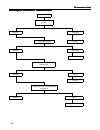
Maintenance manual for sunray hfc4da1-2c china-iv diesel engines 126 fault tree: 检查制动阀连接 检修或更换 制动阀问题 更换制动阀 对制动阀外观检测 插接件问题 更换ecu y n n y 检查ecu插接件 y 检修或更换 n 联系技术支持 n check the connection of brake valve. Connector fault repair or replace it. Check the appearance of brake valve. Fault of brake valve rep...
Page 126
Maintenance manual for sunray hfc4da1-2c china-iv diesel engines 127 2. Dtc p0069 the boost pressure sensor drift p0237 the boost pressure sensor output voltage is below the lower limit (the wiring is short to ground). P0238 the boost pressure sensor output voltage is above the upper limit (the wiri...
Page 127
Maintenance manual for sunray hfc4da1-2c china-iv diesel engines 128 diagnosis hint: the normal boost pressure sensor shall make quick response to the change of accelerator pedal position, so its slow action should not appear or it should not act slower than the change of accelerator pedal position....
Page 128
Maintenance manual for sunray hfc4da1-2c china-iv diesel engines 129 fault tree: check the component connector. Connector fault repair or replace it. Repair or replace it. Detect the sensor. Sensor fault replace the sensor. Fault of ecu connector get the technical support. Repair the harness. Check ...
Page 129
Maintenance manual for sunray hfc4da1-2c china-iv diesel engines 130 3. Dtc p0087 the fuel pressure is below the lower limit. P0088 the fuel pressure is above the upper limit. P0191 the forward drift of common rail pressure sensor is too large. P0192 the common rail pressure sensor output voltage is...
Page 130
Maintenance manual for sunray hfc4da1-2c china-iv diesel engines 131 terminal ecu a06 power supply terminal of common rail pressure sensor a52 signal terminal of common rail pressure sensor a40 ground terminal of common rail pressure sensor.
Page 131
Maintenance manual for sunray hfc4da1-2c china-iv diesel engines 132 fault tree: read dtc. Fault of fuel metering unit repair accordingly. Check the common rail pressure sensor. Fault of common rail pressure sensor repair accordingly. Repair accordingly. Fault of the low pressure oil circuit fault o...
Page 132
Maintenance manual for sunray hfc4da1-2c china-iv diesel engines 133 inspection for low pressure/hig h pressure oil circuit: low pressure oil circuit check fuel tank supply. Only checking the fuel tank level indicator is not enough, for its indication may be invalid. Is there no fuel in the fuel tan...
Page 133
Maintenance manual for sunray hfc4da1-2c china-iv diesel engines 134 4. Dtc p0116 the dynamic characteristics of coolant temperature sensor are unreliable. P0117 the coolant temperature sensor output voltage is below the lower limit (the wiring is short to ground). P0118 the coolant temperature sens...
Page 134
Maintenance manual for sunray hfc4da1-2c china-iv diesel engines 135 − poor contact between terminal and wire check the harness for any damage. If the harness appears normal, observe the ect indication on the diagnostic tool while moving relevant connector and harness of ect sensor. If the ect indic...
Page 135
Maintenance manual for sunray hfc4da1-2c china-iv diesel engines 136 fault tree: check the sensor connection. Connector fault repair accordingly. Repair accordingly. Replace the sensor. Detect the sensor resistance. (is it consistent with the vehicle condition?) fault of sensor resistance fault of e...
Page 136
Maintenance manual for sunray hfc4da1-2c china-iv diesel engines 137 5. Dtc p0122 the output voltage of accelerator pedal potentiometer 1 is below the lower limit. P0123 the output voltage of accelerator pedal potentiometer 1 is above the upper limit. P0222 the output voltage of accelerator pedal po...
Page 137
Maintenance manual for sunray hfc4da1-2c china-iv diesel engines 138 terminal ecu k28 power supply terminal of app sensor 1 k81 signal terminal of app sensor 1 k67 ground terminal of app sensor 1 k22 power supply terminal of app sensor 2 k60 signal terminal of app sensor 2 k58 ground terminal of app...
Page 138
Maintenance manual for sunray hfc4da1-2c china-iv diesel engines 139 fault tree: repair accordingly. Repair the harness. Repair accordingly. Replace the component. Check the component connector. Connector fault visually check the component. Component fault ecu connector fault check continuity and in...
Page 139
Maintenance manual for sunray hfc4da1-2c china-iv diesel engines 140 6. Dtc p0201 the 1 st cylinder fuel injector circuit is open. P0263 other errors of the 1 st cylinder fuel injector p1200 the forward error correction of the 1 st fuel injector is too large. P1201 the reverse error correction of th...
Page 140
Maintenance manual for sunray hfc4da1-2c china-iv diesel engines 141 fault tree: turn off the ignition switch and check the fuel injector connector. Connector fault repair accordingly. Disconnect the fuel injector and turn on the ignition switch. Does the problem still exist? Refer to “inspection of...
Page 141
Maintenance manual for sunray hfc4da1-2c china-iv diesel engines 142 7. Dtc p0202 the 2 nd cylinder fuel injector circuit is open. P0264 the low end of the 2 nd fuel injector is short to the high end. P0265 the low end of the 2 nd fuel injector is short to the high level. P0266 other errors of the 2...
Page 142
Maintenance manual for sunray hfc4da1-2c china-iv diesel engines 143 fault tree: turn off the ignition switch and check the fuel injector connector. Connector fault repair accordingly. Disconnect the fuel injector and turn on the ignition switch. Does the problem still exist? Refer to “inspection of...
Page 143
Maintenance manual for sunray hfc4da1-2c china-iv diesel engines 144 8. Dtc p0203 the 3 rd cylinder fuel injector circuit is open. P0267 the low end of the 3 rd fuel injector is short to the high end. P0268 the low end of the 3 rd fuel injector is short to the high level. P0269 other errors of the 3...
Page 144
Maintenance manual for sunray hfc4da1-2c china-iv diesel engines 145 fault tree: turn off the ignition switch and check the fuel injector connector. Connector fault repair accordingly. Disconnect the fuel injector and turn on the ignition switch. Does the problem still exist? Refer to “inspection of...
Page 145
Maintenance manual for sunray hfc4da1-2c china-iv diesel engines 146 9. Dtc p0204 the 4 th cylinder fuel injector circuit is open. P0270 the low end of the 4 th fuel injector is short to the high end. P0271 the low end of the 4 th fuel injector is short to the high level. P0272 other errors of the 4...
Page 146
Maintenance manual for sunray hfc4da1-2c china-iv diesel engines 147 fault tree: turn off the ignition switch and check the fuel injector connector. Connector fault repair accordingly. Disconnect the fuel injector and turn on the ignition switch. Does the problem still exist? Refer to “inspection of...
Page 147
Maintenance manual for sunray hfc4da1-2c china-iv diesel engines 148 10. Dtc p0251 the control line of fuel level control unit is open. P0252 the ecu internal driver module of fuel level control unit is overheating. P0253 the control line of fuel level control unit is short to ground. P0254 the cont...
Page 148
Maintenance manual for sunray hfc4da1-2c china-iv diesel engines 149 fault tree: check the connector of fuel metering unit. Repair accordingly. Repair accordingly. Repair the harness. Repair the fuel metering unit. Get the technical support. Connector fault check the ecu connector. Connector fault c...
Page 149
Maintenance manual for sunray hfc4da1-2c china-iv diesel engines 150 11. Dtc p0335 no signal from crankshaft sensor p0336 false signal from crankshaft sensor diagnosis hint: the signal of crankshaft position (ckp) sensor is used for indicating the rotary speed and position of crankshaft. The ckp sen...
Page 150
Maintenance manual for sunray hfc4da1-2c china-iv diesel engines 151 z check if the ground and connection of ecu and engine is reliable and clean. If the dtc is determined to be intermittent failure, please refer to the fault records to find out when the previous dtc is set. Terminal ecu a13 signal ...
Page 151
Maintenance manual for sunray hfc4da1-2c china-iv diesel engines 152 fault tree: check the sensor connection. Connector fault repair accordingly. Check the ecu connector. Connector fault repair accordingly. Repair the harness. Electrical fault check continuity and insulating property. The new sensor...
Page 152
Maintenance manual for sunray hfc4da1-2c china-iv diesel engines 153 12. Dtc p0340 no signal from phase sensor p0341 false signal from phase sensor fault description: the camshaft position (cmp) sensor is a hall effect switch. The ecu shall supply 5v voltage to the 5v reference voltage circuit and a...
Page 153
Maintenance manual for sunray hfc4da1-2c china-iv diesel engines 154 fault tree: check the sensor connection. Connector fault repair accordingly. Visually check the sensor. Sensor fault replace the sensor. Check the ecu connector. Connector fault repair accordingly. Repair accordingly. Repair the ha...
Page 154
Maintenance manual for sunray hfc4da1-2c china-iv diesel engines 155 13. Dtc p0380 the glow plug works without the command from ecu. P0382 the glow plug doesn’t work with the command from ecu. P0383 ecu control line for glow plug is short to ground. P0384 ecu control line for glow plug is short to h...
Page 155
Maintenance manual for sunray hfc4da1-2c china-iv diesel engines 156 fault tree: 检查预热塞接插件 做必要的修理 接插件问题 做必要的修理 检查 ecu接插件 接插件问题 检查连续性和绝缘性 y n y n 电气问题 y 修理线束 更换预热塞 n 问题仍否存在 y 联系技术支持 check the connector of glow plug. Connector fault repair accordingly. Repair accordingly. Check the ecu connector. Conne...
Page 156
Maintenance manual for sunray hfc4da1-2c china-iv diesel engines 157 14. Dtc p0500 error of vehicle speed sensor acquisition hardware p0501 the vehicle speed sensor signal is unreliable. Fault description: vehicle speed sensor (vss) provides vehicle speed signals to ecu. It is a kind of hall effect ...
Page 157
Maintenance manual for sunray hfc4da1-2c china-iv diesel engines 158 fault tree: check the sensor connection. Connector fault repair accordingly. Check the ecu connector. Connector fault repair accordingly. Repair the harness. Electrical fault check continuity and insulating property. Check the vvs....
Page 158
Maintenance manual for sunray hfc4da1-2c china-iv diesel engines 159 15. Dtc p0504 unreliable comparison between main and auxiliary brake pedal signals fault description: the brake switch detects the brake pedal action and sends the signal to ecu. The brake switch is equipped with two switches, viz....
Page 159
Maintenance manual for sunray hfc4da1-2c china-iv diesel engines 160 fault tree: check the component connector. Connector fault repair accordingly. Visually check the component. Component fault replace the component. Ecu connector fault repair accordingly. Check continuity and insulating property. E...
Page 160
Maintenance manual for sunray hfc4da1-2c china-iv diesel engines 161 16. Dtc p0562 too low battery voltage p0563 too high battery voltage p1617 the engine cannot be shut down with too high internal supply voltage. P1618 the engine cannot be shut down with too low internal supply voltage. P1637 too h...
Page 161
Maintenance manual for sunray hfc4da1-2c china-iv diesel engines 162 fault tree: check the battery voltage at igniting. Battery fault charge the battery. Check the battery connection. Fault of battery connectors repair accordingly. Repair accordingly. Check the ecu connector. Connector fault check t...
Page 162
Maintenance manual for sunray hfc4da1-2c china-iv diesel engines 163 17. Dtc p060a communication failure of ecu internal chip cj940 fault description: it is mainly used for monitoring the internal microprocessor integrity failure in ecu to determine whether the ecu program is executed. With engine o...
Page 163
Maintenance manual for sunray hfc4da1-2c china-iv diesel engines 164 18. Dtc p0642 sensor supply voltage 1 is too low. P0643 sensor supply voltage 1 is too high. P0652 sensor supply voltage 2 is too low. P0653 sensor supply voltage 2 is too high. Fault description: due to the nature of sensor, some ...
Page 164
Maintenance manual for sunray hfc4da1-2c china-iv diesel engines 165 fault tree: read dtc. Read dtcs of all sensors corresponding to the power connector match the connector correctly. Provided that the signal lost is caused by a certain sensor, disconnect each sensor one by one until the fault disap...
Page 165
Maintenance manual for sunray hfc4da1-2c china-iv diesel engines 166 19. Dtc p0686 the main relay opens too early. P0687 the main relay opens too late. Fault description: with the ignition switch off, the input circuit of main relay through k47 is actuated by v3 and ecu pin k46 and the electromagnet...
Page 166
Maintenance manual for sunray hfc4da1-2c china-iv diesel engines 167 fault tree: check the relay connector. Connector fault repair accordingly. Check the ecu connector. Connector fault repair accordingly. Repair the harness. Check continuity and insulating property. Electrical fault replace the rela...
Page 167
Maintenance manual for sunray hfc4da1-2c china-iv diesel engines 168 20. Dtc p0704 clutch signals are unreliable. Fault description: transmission control unit (tcu) is integrated with engine control unit (ecu) and calculates optimal time and speed for clutch engagement according to feedback informat...
Page 168
Maintenance manual for sunray hfc4da1-2c china-iv diesel engines 169 fault tree: get the technical support. Repair accordingly. Repair the harness. Replace the clutch switch. Check clutch switch. Clutch switch fault check clutch switch harness. Harness fault check clutch switch power supply voltage....
Page 169
Maintenance manual for sunray hfc4da1-2c china-iv diesel engines 170 21. Dtc p0650 there are faults (short circuit or open circuit) in ecu obd malfunction indicator lamp (mil) output connecting wire. P1619 connection of ecu system mil output connecting wire is short to high level. P161a connection o...
Page 170
Maintenance manual for sunray hfc4da1-2c china-iv diesel engines 171 fault tree: 检查仪表板与 ecu的连接 做必要的修理 接插件问题 检查连续性和绝缘性 y n 电气问题 y 修理线束 更换相应的器件 n 问题仍存在 y 联系技术支持 get the technical support. Repair the harness. Repair accordingly. Check connection between instrument panel and ecu. Connector fault electri...
Page 171
Maintenance manual for sunray hfc4da1-2c china-iv diesel engines 172 22. Dtc p0100 mass air flow (maf) signals measured by air flow meter without correction are too strong or too weak (connection is in open circuit or short circuit). P0101 mass air flow (maf) signals measured by air flow meter with ...
Page 172
Maintenance manual for sunray hfc4da1-2c china-iv diesel engines 173 — additional accessories after sale — secondary ignition wires or coils — solenoid valve — relay — motor in the case of idle running or deceleration, air flow goes through sensor may reach its minimum and this may lead to dtc occur...
Page 173
Maintenance manual for sunray hfc4da1-2c china-iv diesel engines 174 fault tree: 检查空气流量计接插件 做必要的修理 接插件问题 做必要的修理 检查 ecu接插件 接插件问题 检查连续性和绝缘性 y n y n 电气问题 y 修理线束 更换空气流量计 n 问题仍否存在 y 联系技术支持 get the technical support. Repair the harness. Repair accordingly. Repair accordingly. Check air flow meter connecto...
Page 174
Maintenance manual for sunray hfc4da1-2c china-iv diesel engines 175 23. Dtc p0110 connection for additional air temperature sensor of air mass flowmeter is short or open. P0112 temperature for additional air temperature sensor of air mass flowmeter is too low. P0113 temperature for additional air t...
Page 175
Maintenance manual for sunray hfc4da1-2c china-iv diesel engines 176 check harness damage. If the harness seems to be normal, move relevant connector and harness for intake air temperature (iat) sensor and check display about iat on diagnostic tool. If display of iat changes, it is indicated that th...
Page 176
Maintenance manual for sunray hfc4da1-2c china-iv diesel engines 177 24. Dtc p0300 multi-cylinder misfire p0301 the 1 st cylinder misfire p0302 the 2 nd cylinder misfire p0303 the 3 rd cylinder misfire p0304 the 4 th cylinder misfire fault description: ecu determines when engine misfire occurs with ...
Page 177
Maintenance manual for sunray hfc4da1-2c china-iv diesel engines 178 fault tree: 关闭点火开关并检查喷油器接插件 接插件问题 做必要的修理 曲轴位置传感器间隙问题? n y 检查曲轴位置传感器间隙 检查减震皮带轮与传感器 y 重新调整曲轴减震皮带轮安装, 还不行,更换减震皮带轮并进行 齿讯学习 皮带轮与传感器是否干涉 调整曲轴位置传感器间隙 ( 0.6~0.7mm) n y 检查曲轴位置传感器 n 曲轴位置传感器问题 y 更换曲轴位置传感器 联系技术支持 n get the technical support. R...
Page 178
Maintenance manual for sunray hfc4da1-2c china-iv diesel engines 179 25. Dtc p0401 actual fresh air inflow is larger than target air inflow set by egr system. P0402 actual fresh air inflow is smaller than target air inflow set by egr system. P0403 ecu internal drive module of egr valve actuator cont...
Page 179
Maintenance manual for sunray hfc4da1-2c china-iv diesel engines 180 terminal ecu k23 egr position sensor 5v power supply k31 egr position sensor position signal k39 egr position sensor ground a04 egr actuator power supply a19 egr actuator ground.
Page 180
Maintenance manual for sunray hfc4da1-2c china-iv diesel engines 181 fault tree: repair accordingly. Repair accordingly. Repair the harness. Get the technical support. Replace components. Does the problem still exist? Electrical fault check for continuity and insulating property. Replace the actuato...
Page 181
Maintenance manual for sunray hfc4da1-2c china-iv diesel engines 182 26. Dtc p0480 ecu fan i control wire is open p0481 ecu fan ii control wire is open. P0483 ecu fan i control wire internal drive module is overheated. P0484 ecu fan ii control wire internal drive module is overheated. P0691 ecu fan ...
Page 182
Maintenance manual for sunray hfc4da1-2c china-iv diesel engines 183 fault tree: repair accordingly. Check relay connectors. Connector fault check ecu connectors. Connector fault check continuity and insulating property.. Electrical fault repair the harness. Repair accordingly. Replace the relay (ca...
Page 183
Maintenance manual for sunray hfc4da1-2c china-iv diesel engines 184 27. Dtc p0487 throttle valve actuator control wire is open. P0488 ecu internal drive module of throttle valve actuator is overheated. P2141 throttle valve actuator control wire is short to ground. P2142 throttle valve actuator cont...
Page 184
Maintenance manual for sunray hfc4da1-2c china-iv diesel engines 185 fault tree: check throttle valve actuator connection. Connector fault repair or replace. Check throttle valve appearance. Throttle valve faults check ecu connectors. Replace the ecu. Repair or replace. Replace the throttle valve. G...
Page 185
Maintenance manual for sunray hfc4da1-2c china-iv diesel engines 186 28. Dtc p0615 ecu starting motor control wire is open or drive module is overheated. P0616 ecu starting motor control wire is short to ground. P0617 ecu starting motor control wire is short to high level. Fault description: ecu pro...
Page 186
Maintenance manual for sunray hfc4da1-2c china-iv diesel engines 187 fault tree: get the technical support. Repair the harness. Repair accordingly. Repair accordingly. Check starting motor connectors. Connector fault check ecu connectors. Connector fault check for continuity and insulating property ...
Page 187
Maintenance manual for sunray hfc4da1-2c china-iv diesel engines 188 29. Dtc p1605 ecu instrument panel engine speed output connecting wire is short to high level. P1606 ecu instrument panel engine speed output connecting wire is short to ground. P1607 ecu instrument panel engine speed output connec...
Page 188
Maintenance manual for sunray hfc4da1-2c china-iv diesel engines 189 fault tree: 检查仪表板与 ecu的连接 做必要的修理 接插件问题 检查连续性和绝缘性 y n 电气问题 y 修理线束 更换相应的器件 n 问题仍存在 y 联系技术支持 get the technical support. Repair the harness. Repair accordingly. Check connection between instrument panel and ecu. Connector fault check c...
Page 189
Maintenance manual for sunray hfc4da1-2c china-iv diesel engines 190 30. Dtc p1608 ecu instrument panel preheating indicator lamp output connecting wire is short to high level. P1609 ecu instrument panel preheating indicator lamp output connecting wire is short to ground. P160a ecu instrument panel ...
Page 190
Maintenance manual for sunray hfc4da1-2c china-iv diesel engines 191 fault tree: get the technical support. Repair the harness. Repair accordingly. Check connection between instrument panel and ecu. Connector fault check for continuity and insulating property. Electrical fault replace corresponding ...
Page 191
Maintenance manual for sunray hfc4da1-2c china-iv diesel engines 192 31. Dtc p2228 atmosphere pressure sensor output voltage is too low. P2229 atmosphere pressure sensor output voltage is too high. Fault description: atmosphere pressure indicates connection of ignition switch. When engine stops oper...
Page 192
Maintenance manual for sunray hfc4da1-2c china-iv diesel engines 193 fault tree: get the technical support. Repair the harness. Repair accordingly. Check sensor connection. Connector fault check sensor resistance (for conformity with vehicle status). Electrical fault sensor resistance faults does th...
Page 193
Maintenance manual for sunray hfc4da1-2c china-iv diesel engines 194 32. Dtc p2264 there are faults in water level sensor of diesel filter oil-water separator. P2267 water in diesel filter oil-water separator is overflowed. Fault description: main function of oil-water separator is to separate moist...
Page 194
Maintenance manual for sunray hfc4da1-2c china-iv diesel engines 195 fault tree: get the technical support. Repair the harness. Repair accordingly. Replace water level sensor. Repair accordingly. Repair accordingly. Eliminate the fault. Drain filter. Is there still water? Check water level sensor fo...
Page 195
Maintenance manual for sunray hfc4da1-2c china-iv diesel engines 196 33. Dtc p2299 depress accelerator pedal and brake pedal at the same time. Fault description: accelerator pedal assembly consists of two accelerator pedal position (app) sensors. Accelerator pedal position sensors are installed on p...
Page 196
Maintenance manual for sunray hfc4da1-2c china-iv diesel engines 197 fault tree: get the technical support. Replace the harness. Replace it accordingly. Replace it accordingly. Check brake system and acceleration system mechanical parts. Mechanical part failures check accelerator switch adjusting po...
Page 197
Maintenance manual for sunray hfc4da1-2c china-iv diesel engines 198 34. Dtc u0167 in the case of the maximum fault reading, there are eeprom errors/icm time-out communication failures. Fault description: they are mainly taken as integrity failures for ecu internal microprocessor, being applied in d...
Page 198
Maintenance manual for sunray hfc4da1-2c china-iv diesel engines 199 fault tree: get the technical support. Repair the harness. Repair accordingly. Check ecu connectors. Connector fault check continuity and insulating property control circuit failures check ecu. Ecu faults replace the ecu or refresh...
Page 199
Maintenance manual for sunray hfc4da1-2c china-iv diesel engines 200 35. Dtc p0045 supercharger actuator control wire is open. P0046 ecu internal drive module of supercharger actuator control wire is overheated. P0047 supercharger actuator control wire is short to ground. P0048 supercharger actuator...
Page 200
Maintenance manual for sunray hfc4da1-2c china-iv diesel engines 201 fault tree: 检查 ecu的接插件 做必要的修理 控制线路问题 修理线束 检查连续性和绝缘性 接插件问题 检查 ecu y n y n ecu问题 y 更换 ecu或者刷新ecu数据 n 联系技术支持 get the technical support. Repair the harness. Repair accordingly. Check ecu connectors. Connector fault check for continuity...
Page 201
Maintenance manual for sunray hfc4da1-2c china-iv diesel engines 202 36. Dtc p1070 catalytic converter is clogged. P2002 catalytic converter is removed. P2454 catalytic converter front and rear differential pressure is too low. P2455 catalytic converter front and rear differential pressure is too hi...
Page 202
Maintenance manual for sunray hfc4da1-2c china-iv diesel engines 203 fault tree: get the technical support. Repair the harness. Repair or replace. Check the component connector. Connector fault check ecu connectors. Electrical fault check the sensor. Sensor faults replace the sensor. Repair or repla...
Page 203: Preface
Preface preface preface preface this sunray service manual is hereby compiled by the customer service department of jac to help the technical service personnel correctly understand and get familiar with sunray products of jac international better and to provide them with the ability of quick repair ...
Page 204: Body
Body body body body electrical electrical electrical electrical volume volume volume volume content content content contentssss - 1 - body body body body electrical electrical electrical electrical volume volume volume volume content content content contentssss battery battery battery battery and an...
Page 205: Lighting
Body body body body electrical electrical electrical electrical volume volume volume volume content content content contentssss - 2 - installation of etacs.........................................................................................................................................Et 53 et...
Page 206: Audio/
Body body body body electrical electrical electrical electrical volume volume volume volume content content content contentssss - 3 - audio/ audio/ audio/ audio/video video video video system system system system radio.....................................................................................
Page 207: Air
Body body body body electrical electrical electrical electrical volume volume volume volume content content content contentssss - 4 - air air air air conditioner conditioner conditioner conditioner air conditioner..........................................................................................
Page 208
Body body body body electrical electrical electrical electrical volume volume volume volume content content content contentssss - 5 - turn signal lamp and hazard warning lamp......................................................................................................Ec 237 small lamp..........
Page 209: Battery
Sc sc sc sc battery battery battery battery and and and and charging charging charging charging system system system system - 1 - battery battery battery battery and and and and charging charging charging charging system system system system applied models: sunray products manufactured by jac subjec...
Page 210
Sc sc sc sc battery battery battery battery and and and and charging charging charging charging system system system system - 2 - instruction instruction instruction instruction and and and and operation operation operation operation battery battery battery battery maintenance-free battery is adopte...
Page 211
Sc sc sc sc battery battery battery battery and and and and charging charging charging charging system system system system - 3 - instruction instruction instruction instruction and and and and operatio operatio operatio operation n n n precautions precautions precautions precautions of of of of bat...
Page 212
Sc sc sc sc battery battery battery battery and and and and charging charging charging charging system system system system - 4 - instruction instruction instruction instruction and and and and operation operation operation operation generator generator generator generator air-cooled generator is ad...
Page 213
Sc sc sc sc battery battery battery battery and and and and charging charging charging charging system system system system - 5 - diagnosis diagnosis diagnosis diagnosis and and and and testing testing testing testing maintenance maintenance maintenance maintenance of of of of battery battery batter...
Page 214
Sc sc sc sc battery battery battery battery and and and and charging charging charging charging system system system system - 6 - charging current for battery can return to normal gradually. In the process of charging, if there is a large quantity of acid spraying out from battery vent, stop chargin...
Page 215
Sc sc sc sc battery battery battery battery and and and and charging charging charging charging system system system system - 7 - diagnosis diagnosis diagnosis diagnosis and and and and test test test test 1. Fault diagnosis of battery fault fault fault fault fault fault fault fault symptoms symptom...
Page 216
Sc sc sc sc battery battery battery battery and and and and charging charging charging charging system system system system - 8 - diagnosis diagnosis diagnosis diagnosis and and and and test test test test 1. Fault diagnosis of battery fault fault fault fault fault fault fault fault symptoms symptom...
Page 217
Sc sc sc sc battery battery battery battery and and and and charging charging charging charging system system system system - 9 - diagnosis diagnosis diagnosis diagnosis and and and and test test test test 1. Fault diagnosis of battery fault fault fault fault fault fault fault fault symptoms symptom...
Page 218
Sc sc sc sc battery battery battery battery and and and and charging charging charging charging system system system system - 10 - diagnosis diagnosis diagnosis diagnosis and and and and test test test test fault fault fault fault determination determination determination determination of of of of b...
Page 219
Sc sc sc sc battery battery battery battery and and and and charging charging charging charging system system system system - 11 - diagnosis diagnosis diagnosis diagnosis and and and and test test test test fault fault fault fault determination determination determination determination of of of of g...
Page 220
Sc sc sc sc battery battery battery battery and and and and charging charging charging charging system system system system - 12 - diagnosis diagnosis diagnosis diagnosis and and and and test test test test operating operating operating operating principle principle principle principle of of of of g...
Page 221
Sc sc sc sc battery battery battery battery and and and and charging charging charging charging system system system system - 13 - diagnosis diagnosis diagnosis diagnosis and and and and test test test test precautions precautions precautions precautions of of of of generator generator generator gen...
Page 222
Sc sc sc sc battery battery battery battery and and and and charging charging charging charging system system system system - 14 - removal removal removal removal and and and and installation installation installation installation removal removal removal removal of of of of battery battery battery b...
Page 223
Sc sc sc sc battery battery battery battery and and and and charging charging charging charging system system system system - 15 - removal removal removal removal and and and and installation installation installation installation removal removal removal removal of of of of battery battery battery b...
Page 224
Sc sc sc sc battery battery battery battery and and and and charging charging charging charging system system system system - 16 - removal removal removal removal and and and and installation installation installation installation installation installation installation installation of of of of batte...
Page 225
Sc sc sc sc battery battery battery battery and and and and charging charging charging charging system system system system - 17 - removal removal removal removal and and and and installation installation installation installation installation installation installation installation of of of of batte...
Page 226
Sc sc sc sc battery battery battery battery and and and and charging charging charging charging system system system system - 18 - removal removal removal removal and and and and installation installation installation installation removal removal removal removal of of of of generator generator gener...
Page 227
Sc sc sc sc battery battery battery battery and and and and charging charging charging charging system system system system - 19 - removal removal removal removal and and and and installation installation installation installation removal removal removal removal of of of of generator generator gener...
Page 228
Sc sc sc sc battery battery battery battery and and and and charging charging charging charging system system system system - 20 - removal removal removal removal and and and and installation installation installation installation removal removal removal removal of of of of generator generator gener...
Page 229
Sc sc sc sc battery battery battery battery and and and and charging charging charging charging system system system system - 21 - removal removal removal removal and and and and installation installation installation installation installation installation installation installation of of of of gener...
Page 230
Sc sc sc sc battery battery battery battery and and and and charging charging charging charging system system system system - 22 -.
Page 231: Instrument
Ip instrument instrument instrument instrument and and and and warning warning warning warning system system system system - 23 - instrument instrument instrument instrument and and and and warning warning warning warning system system system system applied models: sunray products manufactured by ja...
Page 232
Ip instrument instrument instrument instrument and and and and warning warning warning warning system system system system - 24 - instruction instruction instruction instruction and and and and operation operation operation operation combination combination combination combination instrument instrum...
Page 233
Ip instrument instrument instrument instrument and and and and warning warning warning warning system system system system - 25 - instruction instruction instruction instruction and and and and operation operation operation operation performance performance performance performance characteristics ch...
Page 234
Ip instrument instrument instrument instrument and and and and warning warning warning warning system system system system - 26 - diagnosis diagnosis diagnosis diagnosis and and and and test test test test function function function function description description description description of of of o...
Page 235
Ip instrument instrument instrument instrument and and and and warning warning warning warning system system system system - 27 - diagnosis diagnosis diagnosis diagnosis and and and and test test test test function function function function description description description description of of of o...
Page 236
Ip instrument instrument instrument instrument and and and and warning warning warning warning system system system system - 28 - diagnosis diagnosis diagnosis diagnosis and and and and test test test test function function function function description description description description of of of o...
Page 237
Ip instrument instrument instrument instrument and and and and warning warning warning warning system system system system - 29 - diagnosis diagnosis diagnosis diagnosis and and and and test test test test function function function function description description description description of of of o...
Page 238
Ip instrument instrument instrument instrument and and and and warning warning warning warning system system system system - 30 - diagnosis diagnosis diagnosis diagnosis and and and and test test test test function function function function description description description description of of of o...
Page 239
Ip instrument instrument instrument instrument and and and and warning warning warning warning system system system system - 31 - diagnosis diagnosis diagnosis diagnosis and and and and test test test test function function function function description description description description of of of o...
Page 240
Ip instrument instrument instrument instrument and and and and warning warning warning warning system system system system - 32 - diagnosis diagnosis diagnosis diagnosis and and and and test test test test definitions definitions definitions definitions of of of of instrument instrument instrument i...
Page 241
Ip instrument instrument instrument instrument and and and and warning warning warning warning system system system system - 33 - removal removal removal removal and and and and installation installation installation installation removal removal removal removal of of of of the the the the instrument...
Page 242
Ip instrument instrument instrument instrument and and and and warning warning warning warning system system system system - 34 - removal removal removal removal and and and and installation installation installation installation removal removal removal removal of of of of the the the the instrument...
Page 243
Ip instrument instrument instrument instrument and and and and warning warning warning warning system system system system - 35 - specification specification specification specification technical technical technical technical parameter parameter parameter parameter of of of of the the the the instru...
Page 244
Ip instrument instrument instrument instrument and and and and warning warning warning warning system system system system - 36 -.
Page 245: Etacs
Et et et et etacs etacs etacs etacs body body body body computer computer computer computer - 37 - etacs etacs etacs etacs body body body body computer computer computer computer applied models: sunray products manufactured by jac subject page instruction instruction instruction instruction and and ...
Page 246
Et et et et etacs etacs etacs etacs body body body body computer computer computer computer - 38 - instruction instruction instruction instruction and and and and operation operation operation operation etacs etacs etacs etacs body body body body computer computer computer computer sunray etacs is f...
Page 247
Et et et et etacs etacs etacs etacs body body body body computer computer computer computer - 39 - instruction instruction instruction instruction and and and and operation operation operation operation introduction introduction introduction introduction to to to to etacs etacs etacs etacs functions...
Page 248
Et et et et etacs etacs etacs etacs body body body body computer computer computer computer - 40 - diagnosis diagnosis diagnosis diagnosis and and and and testing testing testing testing system system system system structure structure structure structure system structure chart: 1. Sunray etacs is a ...
Page 249
Et et et et etacs etacs etacs etacs body body body body computer computer computer computer - 41 - diagnosis diagnosis diagnosis diagnosis and and and and testing testing testing testing introduction introduction introduction introduction to to to to etacs etacs etacs etacs functions functions funct...
Page 250
Et et et et etacs etacs etacs etacs body body body body computer computer computer computer - 42 - diagnosis diagnosis diagnosis diagnosis and and and and testing testing testing testing introduction introduction introduction introduction to to to to etacs etacs etacs etacs functions functions funct...
Page 251
Et et et et etacs etacs etacs etacs body body body body computer computer computer computer - 43 - diagnosis diagnosis diagnosis diagnosis and and and and testing testing testing testing introduction introduction introduction introduction to to to to etacs etacs etacs etacs functions functions funct...
Page 252
Et et et et etacs etacs etacs etacs body body body body computer computer computer computer - 44 - diagnosis diagnosis diagnosis diagnosis and and and and testing testing testing testing introduction introduction introduction introduction to to to to etacs etacs etacs etacs functions functions funct...
Page 253
Et et et et etacs etacs etacs etacs body body body body computer computer computer computer - 45 - diagnosis diagnosis diagnosis diagnosis and and and and testing testing testing testing introduction introduction introduction introduction to to to to etacs etacs etacs etacs functions functions funct...
Page 254
Et et et et etacs etacs etacs etacs body body body body computer computer computer computer - 46 - diagnosis diagnosis diagnosis diagnosis and and and and testing testing testing testing introduction introduction introduction introduction to to to to etacs etacs etacs etacs functions functions funct...
Page 255
Et et et et etacs etacs etacs etacs body body body body computer computer computer computer - 47 - diagnosis diagnosis diagnosis diagnosis and and and and testing testing testing testing control control control control strategy strategy strategy strategy s/n item function 1 washer & wiper control tu...
Page 256
Et et et et etacs etacs etacs etacs body body body body computer computer computer computer - 48 - diagnosis diagnosis diagnosis diagnosis and and and and testing testing testing testing control control control control strategy strategy strategy strategy s/n item function 12 key management control w...
Page 257
Et et et et etacs etacs etacs etacs body body body body computer computer computer computer - 49 - diagnosis diagnosis diagnosis diagnosis and and and and testing testing testing testing diagnosis diagnosis diagnosis diagnosis and and and and service service service service s/n function service meth...
Page 258
Et et et et etacs etacs etacs etacs body body body body computer computer computer computer - 50 - diagnosis diagnosis diagnosis diagnosis and and and and testing testing testing testing etacs etacs etacs etacs pin pin pin pin definition definition definition definition port no. Port name input/outp...
Page 259
Et et et et etacs etacs etacs etacs body body body body computer computer computer computer - 51 - diagnosis diagnosis diagnosis diagnosis and and and and testing testing testing testing etacs etacs etacs etacs pin pin pin pin definition definition definition definition (continued) (continued) (cont...
Page 260
Et et et et etacs etacs etacs etacs body body body body computer computer computer computer - 52 - removal/installation removal/installation removal/installation removal/installation removal removal removal removal of of of of etacs etacs etacs etacs 1. Disconnect the negative cable of battery. 2. R...
Page 261
Et et et et etacs etacs etacs etacs body body body body computer computer computer computer - 53 - removal/installation removal/installation removal/installation removal/installation installation installation installation installation of of of of etacs etacs etacs etacs 1. Connect the harness connec...
Page 262
Et et et et etacs etacs etacs etacs body body body body computer computer computer computer - 54 - specification specification specification specification parameters parameters parameters parameters electrical parameter requirement operating voltage dc12v operating voltage range dc9v~dc16v quiescent...
Page 263: Lighting
Lt lt lt lt lighting lighting lighting lighting system system system system - 55 - lighting lighting lighting lighting system system system system applied models: sunray products manufactured by jac subject page instruction instruction instruction instruction and and and and operation operation oper...
Page 264
Lt lt lt lt lighting lighting lighting lighting system system system system - 56 - instruction instruction instruction instruction and and and and operation operation operation operation lighting lighting lighting lighting system system system system sunray front lamps (headlamps) are installed on b...
Page 265
Lt lt lt lt lighting lighting lighting lighting system system system system - 57 - instruction instruction instruction instruction and and and and operation operation operation operation tail tail tail tail lamps lamps lamps lamps.
Page 266
Lt lt lt lt lighting lighting lighting lighting system system system system - 58 - instruction instruction instruction instruction and and and and operation operation operation operation lighting lighting lighting lighting configuration configuration configuration configuration table table table tab...
Page 267
Lt lt lt lt lighting lighting lighting lighting system system system system - 59 - instruction instruction instruction instruction and and and and operation operation operation operation introduction introduction introduction introduction to to to to functions functions functions functions 1. Positi...
Page 268
Lt lt lt lt lighting lighting lighting lighting system system system system - 60 - instruction instruction instruction instruction and and and and operation operation operation operation introduction introduction introduction introduction to to to to functions functions functions functions 5. Front ...
Page 269
Lt lt lt lt lighting lighting lighting lighting system system system system - 61 - instruction instruction instruction instruction and and and and operation operation operation operation introduction introduction introduction introduction to to to to functions functions functions functions 9. Hazard...
Page 270
Lt lt lt lt lighting lighting lighting lighting system system system system - 62 - diagnosis diagnosis diagnosis diagnosis and and and and testing testing testing testing fault fault fault fault diagnosis diagnosis diagnosis diagnosis 1. Front fog lamp diagnosis step operation yes no 1 ①turn on the ...
Page 271
Lt lt lt lt lighting lighting lighting lighting system system system system - 63 - diagnosis diagnosis diagnosis diagnosis and and and and testing testing testing testing fault fault fault fault diagnosis diagnosis diagnosis diagnosis 2. Turn signal indicator diagnosis step operation yes no 1 turn o...
Page 272
Lt lt lt lt lighting lighting lighting lighting system system system system - 64 - diagnosis diagnosis diagnosis diagnosis and and and and testing testing testing testing fault fault fault fault diagnosis diagnosis diagnosis diagnosis 3. High-mounted brake lamp failed step operation yes no 1 is the ...
Page 273
Lt lt lt lt lighting lighting lighting lighting system system system system - 65 - diagnosis diagnosis diagnosis diagnosis and and and and testing testing testing testing fault fault fault fault diagnosis diagnosis diagnosis diagnosis 4. Ceiling lamp failed step operation yes no 1 check if the bulb ...
Page 274
Lt lt lt lt lighting lighting lighting lighting system system system system - 66 - diagnosis diagnosis diagnosis diagnosis and and and and testing testing testing testing fault fault fault fault diagnosis diagnosis diagnosis diagnosis 5. Glove box lamp failed step operation yes no 1 is the fuse blow...
Page 275
Lt lt lt lt lighting lighting lighting lighting system system system system - 67 - diagnosis diagnosis diagnosis diagnosis and and and and testing testing testing testing fault fault fault fault diagnosis diagnosis diagnosis diagnosis 6. Both high and low beams failed step operation yes no 1 set the...
Page 276
Lt lt lt lt lighting lighting lighting lighting system system system system - 68 - diagnosis diagnosis diagnosis diagnosis and and and and testing testing testing testing fault fault fault fault diagnosis diagnosis diagnosis diagnosis 7. Only high beam failed step operation yes no 1 check if the hig...
Page 277
Lt lt lt lt lighting lighting lighting lighting system system system system - 69 - diagnosis diagnosis diagnosis diagnosis and and and and testing testing testing testing fault fault fault fault diagnosis diagnosis diagnosis diagnosis 8. Low beam failed step operation yes no 1 check lamps and wiring...
Page 278
Lt lt lt lt lighting lighting lighting lighting system system system system - 70 - diagnosis diagnosis diagnosis diagnosis and and and and testing testing testing testing fault fault fault fault diagnosis diagnosis diagnosis diagnosis 9. Diagnostic program for front rear fog lamp step operation yes ...
Page 279
Lt lt lt lt lighting lighting lighting lighting system system system system - 71 - diagnosis diagnosis diagnosis diagnosis and and and and testing testing testing testing fault fault fault fault diagnosis diagnosis diagnosis diagnosis 10. Rear fog lamp failed with front fog lamp and rear fog lamp tu...
Page 280
Lt lt lt lt lighting lighting lighting lighting system system system system - 72 - diagnosis diagnosis diagnosis diagnosis and and and and testing testing testing testing fault fault fault fault diagnosis diagnosis diagnosis diagnosis 11. Diagnostic program for reversing lamps step operation yes no ...
Page 281
Lt lt lt lt lighting lighting lighting lighting system system system system - 73 - diagnosis diagnosis diagnosis diagnosis and and and and testing testing testing testing fault fault fault fault diagnosis diagnosis diagnosis diagnosis 12. Diagnostic program for brake lamps step operation yes no 1 tu...
Page 282
Lt lt lt lt lighting lighting lighting lighting system system system system - 74 - diagnosis diagnosis diagnosis diagnosis and and and and testing testing testing testing fault fault fault fault diagnosis diagnosis diagnosis diagnosis 13. Hazard warning lamp failed but with normal operation of turn ...
Page 283
Lt lt lt lt lighting lighting lighting lighting system system system system - 75 - diagnosis diagnosis diagnosis diagnosis and and and and testing testing testing testing fault fault fault fault diagnosis diagnosis diagnosis diagnosis 14. Turn signal lamp failed but with normal operation of hazard w...
Page 284
Lt lt lt lt lighting lighting lighting lighting system system system system - 76 - removal/installation removal/installation removal/installation removal/installation removal removal removal removal of of of of headlamp headlamp headlamp headlamp 1. Disconnect the negative cable of battery. 2. Remov...
Page 285
Lt lt lt lt lighting lighting lighting lighting system system system system - 77 - removal/installation removal/installation removal/installation removal/installation removal removal removal removal of of of of clearance clearance clearance clearance lamps lamps lamps lamps 1. Disconnect the negativ...
Page 286
Lt lt lt lt lighting lighting lighting lighting system system system system - 78 - removal/installation removal/installation removal/installation removal/installation removal removal removal removal of of of of front front front front fog fog fog fog lamps lamps lamps lamps 1. Disconnect the negativ...
Page 287
Lt lt lt lt lighting lighting lighting lighting system system system system - 79 - removal/installation removal/installation removal/installation removal/installation removal removal removal removal of of of of ceiling ceiling ceiling ceiling lamps lamps lamps lamps 1. Disconnect the negative cable ...
Page 288
Lt lt lt lt lighting lighting lighting lighting system system system system - 80 - removal/installation removal/installation removal/installation removal/installation removal removal removal removal of of of of rear rear rear rear tail tail tail tail lamps lamps lamps lamps 1. Disconnect the negativ...
Page 289
Lt lt lt lt lighting lighting lighting lighting system system system system - 81 - removal/installation removal/installation removal/installation removal/installation removal removal removal removal of of of of high-mounted high-mounted high-mounted high-mounted brake brake brake brake lamp lamp lam...
Page 290
Lt lt lt lt lighting lighting lighting lighting system system system system - 82 - removal/installation removal/installation removal/installation removal/installation removal removal removal removal of of of of rear rear rear rear fog fog fog fog lamp lamp lamp lamp 1. Disconnect the negative cable ...
Page 291
Lt lt lt lt lighting lighting lighting lighting system system system system - 83 - specification specification specification specification basic basic basic basic parameters parameters parameters parameters s/n name bulb type power 1 front combination lamp high/low beam h4 12v 60/55w 60/55w h4 12v 6...
Page 292
Lt lt lt lt lighting lighting lighting lighting system system system system - 84 -.
Page 293: Wiper
Ww ww ww ww wiper wiper wiper wiper and and and and washer washer washer washer system system system system - 85 - wiper wiper wiper wiper and and and and washer washer washer washer system system system system applied models: sunray products manufactured by jac subject page instruction instruction ...
Page 294
Ww wiper wiper wiper wiper and and and and washer washer washer washer system system system system - 86 - instruction instruction instruction instruction and and and and operation operation operation operation wiper wiper wiper wiper system system system system wiper system is the system used for cl...
Page 295
Ww ww ww ww wiper wiper wiper wiper and and and and washer washer washer washer system system system system - 87 - instruction instruction instruction instruction and and and and operation operation operation operation mounting mounting mounting mounting position position position position of of of ...
Page 296
Ww wiper wiper wiper wiper and and and and washer washer washer washer system system system system - 88 - instruction instruction instruction instruction and and and and operation operation operation operation mounting mounting mounting mounting position position position position of of of of wiper ...
Page 297
Ww ww ww ww wiper wiper wiper wiper and and and and washer washer washer washer system system system system - 89 - instruction instruction instruction instruction and and and and operation operation operation operation operation operation operation operation of of of of wiper wiper wiper wiper syste...
Page 298
Ww wiper wiper wiper wiper and and and and washer washer washer washer system system system system - 90 - instruction instruction instruction instruction and and and and operation operation operation operation operation operation operation operation of of of of wiper wiper wiper wiper system system ...
Page 299
Ww ww ww ww wiper wiper wiper wiper and and and and washer washer washer washer system system system system - 91 - diagnostic diagnostic diagnostic diagnostic test test test test definitions definitions definitions definitions of of of of pins pins pins pins no. 1 2 3 4 5 color red green blue yellow...
Page 300
Ww wiper wiper wiper wiper and and and and washer washer washer washer system system system system - 92 - diagnostic diagnostic diagnostic diagnostic test test test test troubleshooting troubleshooting troubleshooting troubleshooting 1. Fault mode: no matter what gear is the wiper switch at, there a...
Page 301
Ww ww ww ww wiper wiper wiper wiper and and and and washer washer washer washer system system system system - 93 - diagnostic diagnostic diagnostic diagnostic test test test test troubleshooting troubleshooting troubleshooting troubleshooting 4. Fault mode: no operation at int gear only step operati...
Page 302
Ww wiper wiper wiper wiper and and and and washer washer washer washer system system system system - 94 - diagnostic diagnostic diagnostic diagnostic test test test test troubleshooting troubleshooting troubleshooting troubleshooting 6. Fault mode: deviation of the wiper blade form its original posi...
Page 303
Ww ww ww ww wiper wiper wiper wiper and and and and washer washer washer washer system system system system - 95 - removal removal removal removal and and and and installation installation installation installation removal removal removal removal of of of of the the the the wiper wiper wiper wiper 1...
Page 304
Ww wiper wiper wiper wiper and and and and washer washer washer washer system system system system - 96 - removal removal removal removal and and and and installation installation installation installation removal removal removal removal of of of of the the the the wiper wiper wiper wiper 5. Take do...
Page 305
Ww ww ww ww wiper wiper wiper wiper and and and and washer washer washer washer system system system system - 97 - removal removal removal removal and and and and installation installation installation installation removal removal removal removal of of of of the the the the windshield windshield win...
Page 306
Ww wiper wiper wiper wiper and and and and washer washer washer washer system system system system - 98 - removal removal removal removal and and and and installation installation installation installation removal removal removal removal of of of of the the the the wiper wiper wiper wiper washing wa...
Page 307
Ww ww ww ww wiper wiper wiper wiper and and and and washer washer washer washer system system system system - 99 - specification specification specification specification technical technical technical technical parameter parameter parameter parameter no load loaded 4.4n.M low speed high speed low sp...
Page 308
Ww wiper wiper wiper wiper and and and and washer washer washer washer system system system system - 100 -.
Page 309: Reversing
Pt pt pt pt reversing reversing reversing reversing parking parking parking parking assistance assistance assistance assistance system system system system - 101 - reversing reversing reversing reversing radar radar radar radar applied models: sunray products manufactured by jac subject page instruc...
Page 310
Pt pt pt pt reversing reversing reversing reversing parking parking parking parking assistance assistance assistance assistance system system system system - 102 - instruction instruction instruction instruction and and and and operation operation operation operation reversing reversing reversing re...
Page 311
Pt pt pt pt reversing reversing reversing reversing parking parking parking parking assistance assistance assistance assistance system system system system - 103 - instruction instruction instruction instruction and and and and operation operation operation operation operating operating operating op...
Page 312
Pt pt pt pt reversing reversing reversing reversing parking parking parking parking assistance assistance assistance assistance system system system system - 104 - diagnosis diagnosis diagnosis diagnosis and and and and test test test test definitions definitions definitions definitions of of of of ...
Page 313
Pt pt pt pt reversing reversing reversing reversing parking parking parking parking assistance assistance assistance assistance system system system system - 105 - diagnosis diagnosis diagnosis diagnosis and and and and test test test test definitions definitions definitions definitions of of of of ...
Page 314
Pt pt pt pt reversing reversing reversing reversing parking parking parking parking assistance assistance assistance assistance system system system system - 106 - diagnosis diagnosis diagnosis diagnosis and and and and test test test test possible possible possible possible conditions conditions co...
Page 315
Pt pt pt pt reversing reversing reversing reversing parking parking parking parking assistance assistance assistance assistance system system system system - 107 - diagnosis diagnosis diagnosis diagnosis and and and and test test test test possible possible possible possible conditions conditions co...
Page 316
Pt pt pt pt reversing reversing reversing reversing parking parking parking parking assistance assistance assistance assistance system system system system - 108 - removal removal removal removal and and and and installation installation installation installation removal removal removal removal of o...
Page 317
Pt pt pt pt reversing reversing reversing reversing parking parking parking parking assistance assistance assistance assistance system system system system - 109 - removal removal removal removal and and and and installation installation installation installation (continued) (continued) (continued) ...
Page 318
Pt pt pt pt reversing reversing reversing reversing parking parking parking parking assistance assistance assistance assistance system system system system - 110 - removal removal removal removal and and and and installation installation installation installation removal removal removal removal of o...
Page 319
Pt pt pt pt reversing reversing reversing reversing parking parking parking parking assistance assistance assistance assistance system system system system - 111 - specification specification specification specification basic basic basic basic parameter parameter parameter parameter of of of of the ...
Page 320
Pt pt pt pt reversing reversing reversing reversing parking parking parking parking assistance assistance assistance assistance system system system system - 112 -.
Page 321: Audio/
Av av av av audio/ audio/ audio/ audio/video video video video system system system system - 113 - audio/ audio/ audio/ audio/video video video video system system system system applied models: sunray products manufactured by jac subject page instruction instruction instruction instruction and and a...
Page 322
Av av av av audio/ audio/ audio/ audio/video video video video system system system system -- 114 -- instruction instruction instruction instruction and and and and operation operation operation operation audio audio audio audio system system system system sunray audio control system, powered by 12v...
Page 323
Av av av av audio/ audio/ audio/ audio/video video video video system system system system -115- instruction instruction instruction instruction and and and and operation operation operation operation introduction introduction introduction introduction to to to to cd cd cd cd player player player pl...
Page 324
Av av av av audio/ audio/ audio/ audio/video video video video system system system system -116- instruction instruction instruction instruction and and and and operation operation operation operation introduction introduction introduction introduction to to to to cd cd cd cd player player player pl...
Page 325
Av av av av audio/ audio/ audio/ audio/video video video video system system system system -117- instruction instruction instruction instruction and and and and operation operation operation operation introduction introduction introduction introduction to to to to cd cd cd cd player player player pl...
Page 326
Av av av av audio/ audio/ audio/ audio/video video video video system system system system -118- instruction instruction instruction instruction and and and and operation operation operation operation introduction introduction introduction introduction to to to to cd cd cd cd player player player pl...
Page 327
Av av av av audio/ audio/ audio/ audio/video video video video system system system system -119- instruction instruction instruction instruction and and and and operation operation operation operation precautions precautions precautions precautions 1. Don’t place cd player under hot environment. 2. ...
Page 328
Av av av av audio/ audio/ audio/ audio/video video video video system system system system -120- instruction instruction instruction instruction and and and and operation operation operation operation precautions precautions precautions precautions 5. Handle the cd properly. 6. The cd is not allowed...
Page 329
Av av av av audio/ audio/ audio/ audio/video video video video system system system system -121- diagnosis diagnosis diagnosis diagnosis and and and and testing testing testing testing troubleshooting troubleshooting troubleshooting troubleshooting 1. 1. 1. 1. Poor poor poor poor reception reception...
Page 330
Av av av av audio/ audio/ audio/ audio/video video video video system system system system -122- diagnosis diagnosis diagnosis diagnosis and and and and testing testing testing testing troubleshooting troubleshooting troubleshooting troubleshooting 2. No radio display with the parking lamp on. Step ...
Page 331
Av av av av audio/ audio/ audio/ audio/video video video video system system system system -123- diagnosis diagnosis diagnosis diagnosis and and and and testing testing testing testing troubleshooting troubleshooting troubleshooting troubleshooting 3. Loudspeaker failed to operate. Step operation ye...
Page 332
Av av av av audio/ audio/ audio/ audio/video video video video system system system system -124- removal/installation removal/installation removal/installation removal/installation removal removal removal removal of of of of cd cd cd cd player player player player 1. Disconnect the negative cable of...
Page 333
Av av av av audio/ audio/ audio/ audio/video video video video system system system system -125- removal/installation removal/installation removal/installation removal/installation removal removal removal removal of of of of loudspeakers loudspeakers loudspeakers loudspeakers 1. Disconnect the negat...
Page 334
Av av av av audio/ audio/ audio/ audio/video video video video system system system system -126- removal/installation removal/installation removal/installation removal/installation removal removal removal removal of of of of loudspeakers loudspeakers loudspeakers loudspeakers 5. Disconnect the conne...
Page 335
Av av av av audio/ audio/ audio/ audio/video video video video system system system system -- 127 -- specification specification specification specification basic basic basic basic parameters parameters parameters parameters of of of of audio audio audio audio system system system system 1. Operatin...
Page 336
Av av av av audio/ audio/ audio/ audio/video video video video system system system system -- 128 -- 4. Technical data for usb-mp3 play: item unit performance parameter frequency response db 100hz/100khz ±3db standard distortion / ≤3% s/n ratio db ≥50 channel separation db ≥45 maximum output power w...
Page 337: Seat
Sb sb sb sb seat seat seat seat belt belt belt belt - 129 - seat seat seat seat belt belt belt belt applied models: sunray products manufactured by jac subject page instruction instruction instruction instruction and and and and operation operation operation operation seat belt.........................
Page 338
Sb sb sb sb seat seat seat seat belt belt belt belt - 130 - instruction instruction instruction instruction and and and and operation operation operation operation seat seat seat seat belt belt belt belt the seat belts are assembled on each seats for sunray. The seat belt is designed to limit the mo...
Page 339
Sb sb sb sb seat seat seat seat belt belt belt belt - 131 - diagnosis diagnosis diagnosis diagnosis and and and and testing testing testing testing t t t troubleshooting roubleshooting roubleshooting roubleshooting fault of driver’s seat belt indicator lamp circuit step operation yes no 1 ①turn the ...
Page 340
Sb sb sb sb seat seat seat seat belt belt belt belt - 132 - removal/installation removal/installation removal/installation removal/installation removal removal removal removal of of of of seat seat seat seat belt belt belt belt 1. Disconnect the connecting wire of battery. 2. Remove the left front d...
Page 341
Sb sb sb sb seat seat seat seat belt belt belt belt - 133 - 4. Remove the b pillar inner trim panel..
Page 342
Sb sb sb sb seat seat seat seat belt belt belt belt - 134 - removal/installation removal/installation removal/installation removal/installation removal removal removal removal of of of of seat seat seat seat belt belt belt belt 5. Remove the covers of top mounting bolts. 6. Remove the top mounting b...
Page 343
Sb sb sb sb seat seat seat seat belt belt belt belt - 135 - removal/installation removal/installation removal/installation removal/installation removal removal removal removal of of of of seat seat seat seat belt belt belt belt buckle buckle buckle buckle lock lock lock lock 1. Disconnect the connec...
Page 344: Power
Gw gw gw gw power power power power window window window window -135- power power power power window window window window applied models: sunray products manufactured by jac subject page instruction instruction instruction instruction and and and and operation operation operation operation power win...
Page 345
Gw gw gw gw power power power power window window window window -136- instruction instruction instruction instruction and and and and operation operation operation operation power power power power window window window window both front door windows for sunray adopt electric up/down operation. Power...
Page 346
Jac multifunctional commercial vehicle company sunray series power window - 137 - instruction instruction instruction instruction and and and and operation operation operation operation instructions instructions instructions instructions for for for for power power power power window window window w...
Page 347
Gw gw gw gw power power power power window window window window -- 138 -- diagnosis diagnosis diagnosis diagnosis and and and and testing testing testing testing troubleshooting troubleshooting troubleshooting troubleshooting 1. All the door power windows cannot operate. Step operation method yes no...
Page 348
Jac multifunctional commercial vehicle company sunray series power window - 139 - diagnosis diagnosis diagnosis diagnosis and and and and testing testing testing testing troubleshooting troubleshooting troubleshooting troubleshooting 2. The left front door power window cannot operate. Step operation...
Page 349
Gw gw gw gw power power power power window window window window -- 140 -- diagnosis diagnosis diagnosis diagnosis and and and and testing testing testing testing troubleshooting troubleshooting troubleshooting troubleshooting 3. The right front door power window cannot operate. Step operation method...
Page 350
Jac multifunctional commercial vehicle company sunray series power window - 141 - diagnosis diagnosis diagnosis diagnosis and and and and testing testing testing testing troubleshooting troubleshooting troubleshooting troubleshooting 4. The auto down function for left front door power window fails. ...
Page 351
Gw gw gw gw power power power power window window window window -- 142 -- removal/installation removal/installation removal/installation removal/installation removal removal removal removal of of of of window window window window regulator regulator regulator regulator motor motor motor motor 1. Dis...
Page 352
Jac multifunctional commercial vehicle company sunray series power window - 143 - removal/installation removal/installation removal/installation removal/installation removal removal removal removal of of of of window window window window regulator regulator regulator regulator switch switch switch s...
Page 353
Gw gw gw gw power power power power window window window window -- 144 -- removal/installation removal/installation removal/installation removal/installation installation installation installation installation of of of of window window window window regulator regulator regulator regulator motor moto...
Page 354
Jac multifunctional commercial vehicle company sunray series power window - 145 - removal/installation removal/installation removal/installation removal/installation installation installation installation installation of of of of window window window window regulator regulator regulator regulator sw...
Page 355
Gw gw gw gw power power power power window window window window -- 146 --.
Page 356: Electric
Em em em em electric electric electric electric rear-view rear-view rear-view rear-view mirro mirro mirro mirro - 147 - electric electric electric electric rear-view rear-view rear-view rear-view mirro mirro mirro mirro applied models: sunray products manufactured by jac subject page instruction ins...
Page 357
Em em em em electric electric electric electric rear-view rear-view rear-view rear-view mirro mirro mirro mirro - 148 - instruction instruction instruction instruction and and and and operation operation operation operation rear rear rear rear view view view view mirror mirror mirror mirror sunray r...
Page 358
Em em em em electric electric electric electric rear-view rear-view rear-view rear-view mirro mirro mirro mirro - 149 - removal removal removal removal and and and and installation installation installation installation removal removal removal removal of of of of rear rear rear rear view view view v...
Page 359
Em em em em electric electric electric electric rear-view rear-view rear-view rear-view mirro mirro mirro mirro - 150 - removal removal removal removal and and and and installation installation installation installation removal removal removal removal of of of of rear rear rear rear view view view v...
Page 360: Horn
Ho ho ho ho horn horn horn horn - 151 - h h h horn orn orn orn applied models: sunray products manufactured by jac subject page instruction instruction instruction instruction and and and and operation operation operation operation h h h horn orn orn orn.................................................
Page 361
Ho ho ho ho horn horn horn horn - 152 - instruction instruction instruction instruction and and and and operation operation operation operation mounting mounting mounting mounting position position position position of of of of horn horn horn horn.
Page 362
Ho ho ho ho horn horn horn horn - 153 - diagnosis diagnosis diagnosis diagnosis and and and and testing testing testing testing troubleshooting troubleshooting troubleshooting troubleshooting 1. Horn always on. Step operation yes no 1 is the vehicle equipped with any anti-theft system? Go to step 2....
Page 363
Ho ho ho ho horn horn horn horn - 154 - diagnosis diagnosis diagnosis diagnosis and and and and testing testing testing testing troubleshooting troubleshooting troubleshooting troubleshooting 2. Horn failed to work. Step operation yes no 1 is the vehicle equipped with any anti-theft system? Go to st...
Page 364
Ho ho ho ho horn horn horn horn - 155 - diagnosis diagnosis diagnosis diagnosis and and and and testing testing testing testing troubleshooting troubleshooting troubleshooting troubleshooting 3. Inferior tone quality of horn. Step operation yes no 1 is the vehicle equipped with any anti-theft system...
Page 365
Ho ho ho ho horn horn horn horn - 156 - removal/installation removal/installation removal/installation removal/installation removal removal removal removal of of of of horn horn horn horn 1. Disconnect the negative cable of battery. 2. Remove the front bumper. 3. Remove the mounting bolt of horn and...
Page 366: Air
At at at at air air air air conditioner conditioner conditioner conditioner - 157 - air air air air conditioner conditioner conditioner conditioner (a/c) (a/c) (a/c) (a/c) applied models: sunray products manufactured by jac subject page instruction instruction instruction instruction and and and and...
Page 367
At at at at air air air air conditioner conditioner conditioner conditioner - 158 - instruction instruction instruction instruction and and and and operation operation operation operation a/c a/c a/c a/c system system system system sunray adopts dual a/c system, with the front and rear a/c controlle...
Page 368
At at at at air air air air conditioner conditioner conditioner conditioner - 159 - instruction instruction instruction instruction and and and and operation operation operation operation precautions precautions precautions precautions 1. Refrigerant is of low freezing point and strong volatility, s...
Page 369
At at at at air air air air conditioner conditioner conditioner conditioner - 160 - instruction instruction instruction instruction and and and and operation operation operation operation precautions precautions precautions precautions 5. R-134a shall be adopted as refrigerant. Use of other kinds of...
Page 370
At at at at air air air air conditioner conditioner conditioner conditioner - 161 - instruction and operation precautions 9. Generally, dust covers are adopted for a/c components, in order to avoid access of sewage, dust and moisture. Dust covers should be removed before operation and sealed after o...
Page 371
At at at at air air air air conditioner conditioner conditioner conditioner - 162 - instruction instruction instruction instruction and and and and operation operation operation operation functional functional functional functional operation operation operation operation 1. “to-face” mode air is adj...
Page 372
At at at at air air air air conditioner conditioner conditioner conditioner - 163 - instruction instruction instruction instruction and and and and operation operation operation operation functional functional functional functional operation operation operation operation 5. Defroster air is adjusted...
Page 373
At at at at air air air air conditioner conditioner conditioner conditioner - 164 - instruction instruction instruction instruction and and and and operation operation operation operation functional functional functional functional operation operation operation operation 9. Front control panel tempe...
Page 374
At at at at air air air air conditioner conditioner conditioner conditioner - 165 - diagnosis diagnosis diagnosis diagnosis and and and and testing testing testing testing operating operating operating operating principle principle principle principle 1. During operation, low pressure gaseous refrig...
Page 375
At at at at air air air air conditioner conditioner conditioner conditioner - 166 - diagnosis diagnosis diagnosis diagnosis and and and and testing testing testing testing operating operating operating operating principle principle principle principle 5. Condensation process. 6. Throttling and expan...
Page 376
At at at at air air air air conditioner conditioner conditioner conditioner - 167 - diagnosis diagnosis diagnosis diagnosis and and and and testing testing testing testing air air air air distribution distribution distribution distribution system system system system introduction introduction introd...
Page 377
At at at at air air air air conditioner conditioner conditioner conditioner - 168 - diagnosis diagnosis diagnosis diagnosis and and and and testing testing testing testing leak leak leak leak test test test test 1. Required tools. R-134a a/c system dye tracer (24 pcs.). General purpose 12v leak dete...
Page 378
At at at at air air air air conditioner conditioner conditioner conditioner - 169 - diagnosis diagnosis diagnosis diagnosis and and and and testing testing testing testing a/c a/c a/c a/c system system system system performance performance performance performance testing testing testing testing 1. T...
Page 379
At at at at air air air air conditioner conditioner conditioner conditioner - 170 - diagnosis diagnosis diagnosis diagnosis and and and and testing testing testing testing a/c a/c a/c a/c system system system system performance performance performance performance testing testing testing testing 5. S...
Page 380
At at at at air air air air conditioner conditioner conditioner conditioner - 171 - diagnosis diagnosis diagnosis diagnosis and and and and testing testing testing testing a/c a/c a/c a/c system system system system performance performance performance performance testing testing testing testing 9. T...
Page 381
At at at at air air air air conditioner conditioner conditioner conditioner - 172 - diagnosis diagnosis diagnosis diagnosis and and and and testing testing testing testing r r r refrigerant efrigerant efrigerant efrigerant recovery recovery recovery recovery 1. Park the vehicle in well-ventilated ar...
Page 382
At at at at air air air air conditioner conditioner conditioner conditioner - 173 - diagnosis and testing refrigerant recovery 5. The refrigerant recovery machine shall start to recover refrigerant and lubricating oil from a/c system, which respectively flows into a fluid reservoir and a removable o...
Page 383
At at at at air air air air conditioner conditioner conditioner conditioner - 174 - diagnosis diagnosis diagnosis diagnosis and and and and testing testing testing testing a/c a/c a/c a/c system system system system performance performance performance performance table table table table engine speed...
Page 384
At at at at air air air air conditioner conditioner conditioner conditioner - 175 - diagnosis diagnosis diagnosis diagnosis and and and and testing testing testing testing a/c a/c a/c a/c system system system system performance performance performance performance table table table table ℃ ℉ kpa psi ...
Page 385
At at at at air air air air conditioner conditioner conditioner conditioner - 176 - diagnosis diagnosis diagnosis diagnosis and and and and testing testing testing testing a/c a/c a/c a/c system system system system performance performance performance performance diagnosis diagnosis diagnosis diagno...
Page 386
At at at at air air air air conditioner conditioner conditioner conditioner - 177 - 10 run the system to check the maintenance result. Is the fault detected and eliminated? System is normal. Go to step 2..
Page 387
At at at at air air air air conditioner conditioner conditioner conditioner - 178 - diagnosis diagnosis diagnosis diagnosis and and and and testing testing testing testing a/c a/c a/c a/c system system system system performance performance performance performance diagnosis diagnosis diagnosis diagno...
Page 388
At at at at air air air air conditioner conditioner conditioner conditioner - 179 - diagnosis diagnosis diagnosis diagnosis and and and and testing testing testing testing a/c a/c a/c a/c system system system system performance performance performance performance diagnosis diagnosis diagnosis diagno...
Page 389
At at at at air air air air conditioner conditioner conditioner conditioner - 180 - diagnosis diagnosis diagnosis diagnosis and and and and testing testing testing testing a/c a/c a/c a/c system system system system performance performance performance performance diagnosis diagnosis diagnosis diagno...
Page 390
At at at at air air air air conditioner conditioner conditioner conditioner - 181 - diagnosis diagnosis diagnosis diagnosis and and and and testing testing testing testing a/c a/c a/c a/c system system system system performance performance performance performance diagnosis diagnosis diagnosis diagno...
Page 391
At at at at air air air air conditioner conditioner conditioner conditioner - 182 - diagnosis diagnosis diagnosis diagnosis and and and and testing testing testing testing a/c a/c a/c a/c system system system system performance performance performance performance diagnosis diagnosis diagnosis diagno...
Page 392
At at at at air air air air conditioner conditioner conditioner conditioner - 183 - is the fault detected and eliminated? Diagnosis diagnosis diagnosis diagnosis and and and and testing testing testing testing a/c a/c a/c a/c system system system system performance performance performance performanc...
Page 393
At at at at air air air air conditioner conditioner conditioner conditioner - 184 - is the fault eliminated?.
Page 394
At at at at air air air air conditioner conditioner conditioner conditioner - 185 - diagnosis diagnosis diagnosis diagnosis and and and and testing testing testing testing a/c a/c a/c a/c system system system system performance performance performance performance diagnosis diagnosis diagnosis diagno...
Page 395
At at at at air air air air conditioner conditioner conditioner conditioner - 186 - diagnosis diagnosis diagnosis diagnosis and and and and testing testing testing testing a/c a/c a/c a/c system system system system performance performance performance performance diagnosis diagnosis diagnosis diagno...
Page 396
At at at at air air air air conditioner conditioner conditioner conditioner - 187 - diagnosis diagnosis diagnosis diagnosis and and and and testing testing testing testing a/c a/c a/c a/c system system system system performance performance performance performance diagnosis diagnosis diagnosis diagno...
Page 397
At at at at air air air air conditioner conditioner conditioner conditioner - 188 - diagnosis diagnosis diagnosis diagnosis and and and and testing testing testing testing a/c a/c a/c a/c system system system system performance performance performance performance diagnosis diagnosis diagnosis diagno...
Page 398
At at at at air air air air conditioner conditioner conditioner conditioner - 189 - diagnosis diagnosis diagnosis diagnosis and and and and testing testing testing testing a/c a/c a/c a/c system system system system performance performance performance performance diagnosis diagnosis diagnosis diagno...
Page 399
At at at at air air air air conditioner conditioner conditioner conditioner - 190 - diagnosis diagnosis diagnosis diagnosis and and and and testing testing testing testing a/c a/c a/c a/c system system system system performance performance performance performance diagnosis diagnosis diagnosis diagno...
Page 400
At at at at air air air air conditioner conditioner conditioner conditioner - 191 - removal/installation removal/installation removal/installation removal/installation removal removal removal removal of of of of front front front front a/c a/c a/c a/c assembly assembly assembly assembly 1. Recover r...
Page 401
At at at at air air air air conditioner conditioner conditioner conditioner - 192 - removal/installation removal/installation removal/installation removal/installation removal removal removal removal of of of of front front front front a/c a/c a/c a/c assembly assembly assembly assembly 5. Remove mo...
Page 402
At at at at air air air air conditioner conditioner conditioner conditioner - 193 - removal/installation removal/installation removal/installation removal/installation removal removal removal removal of of of of top top top top evaporator evaporator evaporator evaporator tank tank tank tank 1. Recov...
Page 403
At at at at air air air air conditioner conditioner conditioner conditioner - 194 - removal/installation removal/installation removal/installation removal/installation removal removal removal removal of of of of top top top top evaporator evaporator evaporator evaporator tank tank tank tank 5. Disco...
Page 404
At at at at air air air air conditioner conditioner conditioner conditioner - 195 - removal/installation removal/installation removal/installation removal/installation removal removal removal removal of of of of front front front front condenser condenser condenser condenser 1. Recover refrigerant. ...
Page 405
At at at at air air air air conditioner conditioner conditioner conditioner - 196 - removal/installation removal/installation removal/installation removal/installation removal removal removal removal of of of of front front front front condenser condenser condenser condenser 5. Disconnect pipeline. ...
Page 406
At at at at air air air air conditioner conditioner conditioner conditioner - 197 - removal/installation removal/installation removal/installation removal/installation removal removal removal removal of of of of bottom bottom bottom bottom condenser condenser condenser condenser 1. Recover refrigera...
Page 407
At at at at air air air air conditioner conditioner conditioner conditioner - 198 - removal/installation removal/installation removal/installation removal/installation removal removal removal removal of of of of heater heater heater heater water water water water tank tank tank tank 1. Recover refri...
Page 408
At at at at air air air air conditioner conditioner conditioner conditioner - 199 - removal/installation removal/installation removal/installation removal/installation removal removal removal removal of of of of heater heater heater heater water water water water tank tank tank tank 5. Remove mounti...
Page 409
At at at at air air air air conditioner conditioner conditioner conditioner - 200 - removal/installation removal/installation removal/installation removal/installation removal/installation removal/installation removal/installation removal/installation of of of of temperature temperature temperature ...
Page 410
At at at at air air air air conditioner conditioner conditioner conditioner - 201 - removal/installation removal/installation removal/installation removal/installation removal/ removal/ removal/ removal/iiiinstallation nstallation nstallation nstallation of of of of mode mode mode mode damper damper...
Page 411
At at at at air air air air conditioner conditioner conditioner conditioner - 202 - removal/installation removal/installation removal/installation removal/installation removal/ removal/ removal/ removal/iiiinstallation nstallation nstallation nstallation of of of of speed speed speed speed governing...
Page 412
At at at at air air air air conditioner conditioner conditioner conditioner - 203 - removal/installation removal/installation removal/installation removal/installation removal/ removal/ removal/ removal/iiiinstallation nstallation nstallation nstallation of of of of internal/external internal/extern...
Page 413
At at at at air air air air conditioner conditioner conditioner conditioner - 204 - removal/installation removal/installation removal/installation removal/installation removal/ removal/ removal/ removal/iiiinstallation nstallation nstallation nstallation of of of of compressor compressor compressor ...
Page 414
At at at at air air air air conditioner conditioner conditioner conditioner - 205 - removal/installation removal/installation removal/installation removal/installation removal/ removal/ removal/ removal/iiiinstallation nstallation nstallation nstallation of of of of compressor compressor compressor ...
Page 415
At at at at air air air air conditioner conditioner conditioner conditioner - 206 - removal/installation removal/installation removal/installation removal/installation installation installation installation installation of of of of compressor compressor compressor compressor assembly assembly assemb...
Page 416
At at at at air air air air conditioner conditioner conditioner conditioner - 207 - removal/installation removal/installation removal/installation removal/installation removal removal removal removal of of of of front front front front a/c a/c a/c a/c control control control control panel panel pane...
Page 417
At at at at air air air air conditioner conditioner conditioner conditioner - 208 - removal/installation removal/installation removal/installation removal/installation removal removal removal removal of of of of front front front front a/c a/c a/c a/c control control control control panel panel pane...
Page 418
At at at at air air air air conditioner conditioner conditioner conditioner - 209 - specification specification specification specification basic basic basic basic parameters parameters parameters parameters name item parameter a/c compressor type: 10-cyliner swash-plate compressor air displacement:...
Page 419
At at at at air air air air conditioner conditioner conditioner conditioner - 210 -.
Page 420: Circuit
Ec ec ec ec circuit circuit circuit circuit diagram diagram diagram diagram - 209 - circuit circuit circuit circuit diagram diagram diagram diagram applied models: sunray products manufactured by jac subject page diagram specification.....................................................................
Page 421
Ec ec ec ec circuit circuit circuit circuit diagram diagram diagram diagram - 210 - instruction this chapter consists of two parts as circuit diagram and harness layout drawing. Circuit diagram start to understand every system form understanding its circuit diagram for circuit diagram indicates all ...
Page 422
Ec ec ec ec circuit circuit circuit circuit diagram diagram diagram diagram - 211 - harness layout drawing mounting and fixed position of main harness and wire connector and route of main harness are indicated in this part. With the help of these harness layout drawings, circuit repair would become ...
Page 423
Ec ec ec ec circuit circuit circuit circuit diagram diagram diagram diagram - 212 - notation the following electrical notations, electrical symbols and abbreviations are adopted in this manual. Notation of circuit diagram.
Page 424
Ec ec ec ec circuit circuit circuit circuit diagram diagram diagram diagram - 213 -.
Page 425
Ec ec ec ec circuit circuit circuit circuit diagram diagram diagram diagram - 214 -.
Page 426
Ec ec ec ec circuit circuit circuit circuit diagram diagram diagram diagram - 215 - wire color description wire color code wire color code black b orange o blue l pink p brown br red r green g violet v gray gr yellow y light green lg white w identification of wire connector codes wire connector iden...
Page 427
Ec ec ec ec circuit circuit circuit circuit diagram diagram diagram diagram - 216 - electrical symbols of circuit diagram.
Page 428
Ec ec ec ec circuit circuit circuit circuit diagram diagram diagram diagram - 217 -.
Page 429
Ec ec ec ec circuit circuit circuit circuit diagram diagram diagram diagram - 218 -.
Page 430
Ec ec ec ec circuit circuit circuit circuit diagram diagram diagram diagram - 219 -.
Page 431
Ec ec ec ec circuit circuit circuit circuit diagram diagram diagram diagram - 220 -.
Page 432
Ec ec ec ec circuit circuit circuit circuit diagram diagram diagram diagram - 221 -.
Page 433
Ec ec ec ec circuit circuit circuit circuit diagram diagram diagram diagram - 222 -.
Page 434
Ec ec ec ec circuit circuit circuit circuit diagram diagram diagram diagram - 223 -.
Page 435
Ec ec ec ec circuit circuit circuit circuit diagram diagram diagram diagram - 224 -.
Page 436
Ec ec ec ec circuit circuit circuit circuit diagram diagram diagram diagram - 225 -.
Page 437
Ec ec ec ec circuit circuit circuit circuit diagram diagram diagram diagram - 226 -.
Page 438
Ec ec ec ec circuit circuit circuit circuit diagram diagram diagram diagram - 227 -.
Page 439
Ec ec ec ec circuit circuit circuit circuit diagram diagram diagram diagram - 228 -.
Page 440
Ec ec ec ec circuit circuit circuit circuit diagram diagram diagram diagram - 229 -.
Page 441
Ec ec ec ec circuit circuit circuit circuit diagram diagram diagram diagram - 230 -.
Page 442
Ec ec ec ec circuit circuit circuit circuit diagram diagram diagram diagram - 231 -.
Page 443
Ec ec ec ec circuit circuit circuit circuit diagram diagram diagram diagram - 232 -.
Page 444
Ec ec ec ec circuit circuit circuit circuit diagram diagram diagram diagram - 233 -.
Page 445
Ec ec ec ec circuit circuit circuit circuit diagram diagram diagram diagram - 234 -.
Page 446
Ec ec ec ec circuit circuit circuit circuit diagram diagram diagram diagram - 235 -.
Page 447
Ec ec ec ec circuit circuit circuit circuit diagram diagram diagram diagram - 236 -.
Page 448
Ec ec ec ec circuit circuit circuit circuit diagram diagram diagram diagram - 237 -.
Page 449
Ec ec ec ec circuit circuit circuit circuit diagram diagram diagram diagram - 238 -.
Page 450
Ec ec ec ec circuit circuit circuit circuit diagram diagram diagram diagram - 239 -.
Page 451
Ec ec ec ec circuit circuit circuit circuit diagram diagram diagram diagram - 240 -.
Page 452
Ec ec ec ec circuit circuit circuit circuit diagram diagram diagram diagram - 241 -.
Page 453
Ec ec ec ec circuit circuit circuit circuit diagram diagram diagram diagram - 242 -.
Page 454
Ec ec ec ec circuit circuit circuit circuit diagram diagram diagram diagram - 243 -.
Page 455
Ec ec ec ec circuit circuit circuit circuit diagram diagram diagram diagram - 244 -.
Page 456
Ec ec ec ec circuit circuit circuit circuit diagram diagram diagram diagram - 245 -.
Page 457
Ec ec ec ec circuit circuit circuit circuit diagram diagram diagram diagram - 246 -.
Page 458
Ec ec ec ec circuit circuit circuit circuit diagram diagram diagram diagram - 247 -.
Page 459
Ec ec ec ec circuit circuit circuit circuit diagram diagram diagram diagram - 248 -.
Page 460
Ec ec ec ec circuit circuit circuit circuit diagram diagram diagram diagram - 249 -.
Page 461
Ec ec ec ec circuit circuit circuit circuit diagram diagram diagram diagram - 250 -.
Page 462
Ec ec ec ec circuit circuit circuit circuit diagram diagram diagram diagram - 251 - main harness specification identification code name identification code name m01 relay box m42 key and faulted door switch m02 left front fog lamp m43 buzzer m03 left headlamp m45 rear air heater m04 left electric ho...
Page 463
Ec ec ec ec circuit circuit circuit circuit diagram diagram diagram diagram - 252 - main harness 1.
Page 464
Ec ec ec ec circuit circuit circuit circuit diagram diagram diagram diagram - 253 - main harness 2.
Page 465
Ec ec ec ec circuit circuit circuit circuit diagram diagram diagram diagram - 254 - engine compartment harness specification identification code name e01 connected to generator control e02 connected to generator positive pole e03 connected to starter control e04 connected to starter positive pole e0...
Page 466
Ec ec ec ec circuit circuit circuit circuit diagram diagram diagram diagram - 255 - left front door harness specification identification code name d01 left window regulator motor d02 left electric rear view mirror d03 window regulator main switch d04 left door loud speaker d06 left door lock actuato...
Page 467
Ec ec ec ec circuit circuit circuit circuit diagram diagram diagram diagram - 256 - right front door harness specification identification code name d11 right power window motor d12 right electric rear view mirror d13 power window auxiliary switch d14 right door loud speaker d16 right door lock actua...
Page 468
Ec ec ec ec circuit circuit circuit circuit diagram diagram diagram diagram - 257 - left tail lamp harness specification identification code name l01 front ceiling lamp l02 left rear combination lamp l03 high-mounted brake lamp l04 reversing radar ecu l05 antenna amplifier l06 rear blower lr01 conne...
Page 469
Ec ec ec ec circuit circuit circuit circuit diagram diagram diagram diagram - 258 - right tail lamp harness specification identification code name n01 intermediate ceiling lamp n02 rear ceiling lamp n03 right rear combination lamp n04 right rear fog lamp nm01 connected to right main harness ground g.
Page 470
Ec ec ec ec circuit circuit circuit circuit diagram diagram diagram diagram - 259 - left back door harness specification identification code name t03 left license plate lamp t04 right license plate lamp lt01 connected to left roof harness ground g.
Page 471
Ec ec ec ec circuit circuit circuit circuit diagram diagram diagram diagram - 260 - rear loud speaker harness specification identification code name s01 left rear loud speaker s02 right rear loud speaker sm01 connected to main harness.
Page 472
Ec ec ec ec circuit circuit circuit circuit diagram diagram diagram diagram - 261 - abs harness specification identification code name b01 abs system control module b02 left front wheel speed sensor b03 right front wheel speed sensor b04 right front wheel speed sensor b05 right rear wheel speed sens...
Page 473
Ec ec ec ec circuit circuit circuit circuit diagram diagram diagram diagram - 262 - fuel tank harness specification identification code name g01 fuel sensor g02 condenser fan motor gm01 connected to main harness 1.
Page 474
Ec ec ec ec circuit circuit circuit circuit diagram diagram diagram diagram - 263 - reversing radar harness specification identification code name r01 left rear fog lamp r02 left external probe r03 left intermediate probe r04 right intermediate probe r05 right external probe rl01 connected to left t...
Page 475: Preface
Preface preface preface preface this sunray service manual is hereby compiled by the customer service department of jac to help the technical service personnel correctly understand and get familiar with sunray products of jac international better and to provide them with the ability of quick repair ...
Page 476: Chassis
Chassis chassis chassis chassis volume volume volume volume contents contents contents contents - 1 - chassis chassis chassis chassis volume volume volume volume content content content contentssss clutch clutch clutch clutch clutch.......................................................................
Page 477: Anti-Lock
Chassis chassis chassis chassis volume volume volume volume contents contents contents contents -2- anti-lock anti-lock anti-lock anti-lock brake brake brake brake system system system system (abs) (abs) (abs) (abs) abs system.............................................................................
Page 478: Steering
Chassis chassis chassis chassis volume volume volume volume contents contents contents contents - 3 - steering steering steering steering system system system system steering system..........................................................................................................................
Page 479: Clutch
Cl cl cl cl clutch clutch clutch clutch - 1- clutch clutch clutch clutch applied models: sunray products manufactured by jac subject page instruction instruction instruction instruction and and and and operation operation operation operation clutch.......................................................
Page 480
Cl cl cl cl clutch clutch clutch clutch - 2- instruction instruction instruction instruction and and and and operation operation operation operation clutch clutch clutch clutch system diagram: diagram of clutch control system 1.Clutch 2.Clutch release cylinder 3.Release fork 4.Release bearing 5.Clut...
Page 481
Cl cl cl cl clutch clutch clutch clutch - 3- instruction instruction instruction instruction and and and and operation operation operation operation operating operating operating operating principle principle principle principle the clutch control is realized via remote hydraulic control of clutch e...
Page 482
Cl cl cl cl clutch clutch clutch clutch - 4- clutch slave cylinder and hydraulic release bearing or in the case of spongy clutch pedal, carry out air bleeding for the system. 1. Loosen bleed bolts of the clutch release cylinder. 2. Step on the clutch pedal slowly until complete air bleeding has been...
Page 483
Cl cl cl cl clutch clutch clutch clutch - 5- common common common common ffffault ault ault ault diagnosis diagnosis diagnosis diagnosis table table table table fault symptom possible cause of fault troubleshooting incapable release incapable release of the clutch means unable functioning of the clu...
Page 484
Cl cl cl cl clutch clutch clutch clutch - 6- fault symptom possible cause of fault troubleshooting noise inspect for following conditions: 1. Improper clutch friction lining. 2. Poor balance 3. Fault in clutch thrust bearing 4. Damage in torsion damping spring of clutch friction lining replace defor...
Page 485
Cl cl cl cl clutch clutch clutch clutch - 7- removal removal removal removal and and and and installation installation installation installation clutch clutch clutch clutch 1. Disconnect the negative cable of battery. 2. Lift the vehicle. 3. Remove the clutch slave cylinder. remove bleed bolts of ...
Page 486
Cl cl cl cl clutch clutch clutch clutch - 8- removal removal removal removal and and and and installation installation installation installation (continued) (continued) (continued) (continued) clutch clutch clutch clutch 5. Remove the rear support pad of the transmission. Jack up the transmission wi...
Page 487
Cl cl cl cl clutch clutch clutch clutch - 9- removal removal removal removal and and and and installation installation installation installation (continued) (continued) (continued) (continued) clutch clutch clutch clutch 11. Remove the release bearing. Attention: do not make the lubricating grease t...
Page 488
Cl cl cl cl clutch clutch clutch clutch - 10- removal removal removal removal and and and and installation installation installation installation (continued) (continued) (continued) (continued) installation installation installation installation of of of of clutch clutch clutch clutch installation: ...
Page 489
Cl cl cl cl clutch clutch clutch clutch - 11- removal removal removal removal and and and and installation installation installation installation (continued) (continued) (continued) (continued) installation installation installation installation of of of of clutch clutch clutch clutch 5. Install the...
Page 490
Cl cl cl cl clutch clutch clutch clutch - 12- removal removal removal removal and and and and installation installation installation installation (continued) (continued) (continued) (continued) clutch clutch clutch clutch master master master master cylinder cylinder cylinder cylinder 1. Disconnect ...
Page 491
Cl cl cl cl clutch clutch clutch clutch - 13- removal removal removal removal and and and and installation installation installation installation (((( continued continued continued continued )))) clutch clutch clutch clutch master master master master cylinder cylinder cylinder cylinder installation...
Page 492
Cl cl cl cl clutch clutch clutch clutch - 14- specification specification specification specification tightening tightening tightening tightening torque torque torque torque part name tightening torque nm quantity clutch master cylinder bolt and nut cap 23~29 3 nut for installing the master cylinder...
Page 493: Manual
Mt mt mt mt manual manual manual manual transmission transmission transmission transmission -15- manual manual manual manual transmission transmission transmission transmission applied models: sunray products manufactured by jac subject page instruction instruction instruction instruction and and an...
Page 494
Mt mt mt mt manual manual manual manual transmission transmission transmission transmission -16- instruction instruction instruction instruction and and and and operation operation operation operation sunray vehicles adopt synchronizer manual-shift mechanical transmissions of good shifting flexibili...
Page 495
Mt mt mt mt manual manual manual manual transmission transmission transmission transmission -17- instruction instruction instruction instruction and and and and operation operation operation operation control control control control gear selector lever and gear shift lever can be controlled through ...
Page 496
Mt mt mt mt manual manual manual manual transmission transmission transmission transmission -18- instruction instruction instruction instruction and and and and operation operation operation operation fault fault fault fault diagnosis diagnosis diagnosis diagnosis common common common common fault f...
Page 497
Mt mt mt mt manual manual manual manual transmission transmission transmission transmission -19- removal/installation removal/installation removal/installation removal/installation manual manual manual manual transmission transmission transmission transmission 1. Remove manual transmission. ● oil dr...
Page 498
Mt mt mt mt manual manual manual manual transmission transmission transmission transmission -20- removal/installation removal/installation removal/installation removal/installation (continued) (continued) (continued) (continued) manual manual manual manual transmission transmission transmission tran...
Page 499
Mt mt mt mt manual manual manual manual transmission transmission transmission transmission -21- removal/installation removal/installation removal/installation removal/installation (continued) (continued) (continued) (continued) manual manual manual manual transmission transmission transmission tran...
Page 500
Mt mt mt mt manual manual manual manual transmission transmission transmission transmission -22- removal/installation removal/installation removal/installation removal/installation (continued) (continued) (continued) (continued) manual manual manual manual transmission transmission transmission tran...
Page 501
Mt mt mt mt manual manual manual manual transmission transmission transmission transmission -23- removal/installation removal/installation removal/installation removal/installation (continued) (continued) (continued) (continued) manual manual manual manual transmission transmission transmission tran...
Page 502
Mt mt mt mt manual manual manual manual transmission transmission transmission transmission -24- removal/installation removal/installation removal/installation removal/installation (continued) (continued) (continued) (continued) manual manual manual manual transmission transmission transmission tran...
Page 503
Mt mt mt mt manual manual manual manual transmission transmission transmission transmission -25- removal/installation removal/installation removal/installation removal/installation (continued) (continued) (continued) (continued) manual manual manual manual transmission transmission transmission tran...
Page 504
Mt mt mt mt manual manual manual manual transmission transmission transmission transmission -26- removal/installation removal/installation removal/installation removal/installation (continued) (continued) (continued) (continued) manual manual manual manual transmission transmission transmission tran...
Page 505
Mt mt mt mt manual manual manual manual transmission transmission transmission transmission -27- instruction instruction instruction instruction and and and and operation operation operation operation exploded exploded exploded exploded view view view view of of of of reverse reverse reverse reverse...
Page 506
Mt mt mt mt manual manual manual manual transmission transmission transmission transmission -28- instruction instruction instruction instruction and and and and operation operation operation operation exploded exploded exploded exploded view view view view of of of of output output output output sha...
Page 507
Mt mt mt mt manual manual manual manual transmission transmission transmission transmission -29- output output output output shaft shaft shaft shaft parts parts parts parts list list list list s/n name qty. S/n name qty. 1 output shaft head needle roller bearing 1 27 thrust washer of 5 th gear 1 2 c...
Page 508
Mt mt mt mt manual manual manual manual transmission transmission transmission transmission -30- instruction instruction instruction instruction and and and and operation operation operation operation exploded exploded exploded exploded view view view view of of of of top top top top cover cover cov...
Page 509
Mt mt mt mt manual manual manual manual transmission transmission transmission transmission -31- top top top top cover cover cover cover assembly assembly assembly assembly parts parts parts parts list list list list s/n name qty. S/n name qty. 1 transmission cover 1 14 hexagon bolt 2 2 outer gear s...
Page 510
Mt mt mt mt manual manual manual manual transmission transmission transmission transmission -32- instruction instruction instruction instruction and and and and operation operation operation operation exploded exploded exploded exploded view view view view of of of of input input input input shaft s...
Page 511
Mt mt mt mt manual manual manual manual transmission transmission transmission transmission -33- instruction instruction instruction instruction and and and and operation operation operation operation exploded exploded exploded exploded view view view view of of of of transmission transmission trans...
Page 512
Mt mt mt mt manual manual manual manual transmission transmission transmission transmission -34- exploded exploded exploded exploded view view view view of of of of countershaft countershaft countershaft countershaft assembly assembly assembly assembly s/n name qty. S/n name qty. 1 circlip 1 6 circl...
Page 513
Mt mt mt mt manual manual manual manual transmission transmission transmission transmission -35- instruction instruction instruction instruction and and and and operation operation operation operation exploded exploded exploded exploded view view view view of of of of housing housing housing housing...
Page 514
Mt mt mt mt manual manual manual manual transmission transmission transmission transmission -36- instruction instruction instruction instruction and and and and operation operation operation operation exploded exploded exploded exploded view view view view of of of of shift shift shift shift fork fo...
Page 515
Mt mt mt mt manual manual manual manual transmission transmission transmission transmission -37- instruction instruction instruction instruction and and and and operation operation operation operation exploded exploded exploded exploded view view view view of of of of transmission transmission trans...
Page 516
Mt mt mt mt manual manual manual manual transmission transmission transmission transmission -38- instruction instruction instruction instruction and and and and operation operation operation operation transmission transmission transmission transmission assembly assembly assembly assembly diagram dia...
Page 517
Mt mt mt mt manual manual manual manual transmission transmission transmission transmission -39- removal/installation removal/installation removal/installation removal/installation (continued) (continued) (continued) (continued) transmission transmission transmission transmission installation 1. Pla...
Page 518
Mt mt mt mt manual manual manual manual transmission transmission transmission transmission -40- removal/installation removal/installation removal/installation removal/installation (continued) (continued) (continued) (continued) transmission transmission transmission transmission 5. Install the fixe...
Page 519
Mt mt mt mt manual manual manual manual transmission transmission transmission transmission -41- removal/installation removal/installation removal/installation removal/installation (continued) (continued) (continued) (continued) transmission transmission transmission transmission 9. Install gear shi...
Page 520
Mt mt mt mt manual manual manual manual transmission transmission transmission transmission -42- removal/installation removal/installation removal/installation removal/installation (continued) (continued) (continued) (continued) transmission transmission transmission transmission 13. Install top cov...
Page 521
Mt mt mt mt manual manual manual manual transmission transmission transmission transmission -43- maintenance maintenance maintenance maintenance parameters parameters parameters parameters tightening tightening tightening tightening torque torque torque torque position technical requirement (n.M) co...
Page 522
Mt mt mt mt manual manual manual manual transmission transmission transmission transmission -44- care care care care and and and and maintenance maintenance maintenance maintenance transmission transmission transmission transmission maintenance maintenance maintenance maintenance 1. Transmission ope...
Page 523: Brake
Br br br br brake brake brake brake system system system system - 45- brake brake brake brake system system system system applied models: sunray products manufactured by jac subject page instruction instruction instruction instruction and and and and operation operation operation operation brake sys...
Page 524
Br br br br brake brake brake brake system system system system - 46 - instruction instruction instruction instruction and and and and operation operation operation operation sunray vehicles’ brake system adopts cross type brake line and the front disc/rear drum brake type. 1.brake master cylinder 2...
Page 525
Br br br br brake brake brake brake system system system system - 47- instruction instruction instruction instruction and and and and operation operation operation operation operating operating operating operating principle principle principle principle brake brake brake brake fluid fluid fluid flui...
Page 526
Br br br br brake brake brake brake system system system system - 48 - ② check the runout with dial indicator. (it is preferable to conduct measurement at points 10mm distant from the disc edge) runout limit: 0.05mm ③ if the disc runout exceeds the specified value, please replace or reprocess it acc...
Page 527
Br br br br brake brake brake brake system system system system - 49- fault fault fault fault diagnosis diagnosis diagnosis diagnosis common common common common fault fault fault fault diagnosis diagnosis diagnosis diagnosis table table table table fault symptom possible cause solution vehicle pull...
Page 528
Br br br br brake brake brake brake system system system system - 50 - removal/installation removal/installation removal/installation removal/installation front front front front brake brake brake brake disc disc disc disc removal 1. Have the vehicle lifted and remove the front wheel. 2. Remove the ...
Page 529
Br br br br brake brake brake brake system system system system - 51- removal/installation removal/installation removal/installation removal/installation installation 1. Install the wheel hub onto the brake disc. Bend the lock lug on the set bolt up. Caution: caution: caution: caution: the left hand...
Page 530
Br br br br brake brake brake brake system system system system - 52 - replacement replacement replacement replacement of of of of front front front front brake brake brake brake disc disc disc disc removal 1. Have the vehicle lifted to remove the front wheel. 2. Remove the plastic cap of brake cali...
Page 531
Br br br br brake brake brake brake system system system system - 53- removal/installation removal/installation removal/installation removal/installation 6. During the installation of new brake lining, please remove the snap ring of brake lining from the brake caliper. 7. Clear any dirt within the m...
Page 532
Br br br br brake brake brake brake system system system system - 54 - removal/installation removal/installation removal/installation removal/installation brake brake brake brake caliper caliper caliper caliper assembly assembly assembly assembly removal 1. Have the vehicle lifted and remove the fro...
Page 533
Br br br br brake brake brake brake system system system system - 55- removal/installation removal/installation removal/installation removal/installation installation 1. Reinstall the brake caliper. 2. Connect the brake hose to the brake caliper. 3. Fix the brake hose onto the shock absorber. 4. Ble...
Page 534
Br br br br brake brake brake brake system system system system - 56 - removal/installation removal/installation removal/installation removal/installation of of of of rear rear rear rear wheel wheel wheel wheel brake brake brake brake shoe shoe shoe shoe removal 1. Release the parking brake lever, h...
Page 535
Br br br br brake brake brake brake system system system system - 57- removal/installation removal/installation removal/installation removal/installation 7. Remove the leading shoe: remove the lock pin and its spring cap. remove the brake shoe lower end from the support. loosen the lower retur...
Page 536
Br br br br brake brake brake brake system system system system - 58 - removal/installation removal/installation removal/installation removal/installation installation 1. Clean the support plate and apply abs fluid onto the bonding point between brake bottom plate and brake shoe. 2. Assemble the tra...
Page 537
Br br br br brake brake brake brake system system system system - 59- parking parking parking parking brake brake brake brake adjustment adjustment adjustment adjustment 1. Release the parking brake and have the vehicle lifted. 2. Release the parking brake regulator. loosen the lock nut. rotate ...
Page 538
Br br br br brake brake brake brake system system system system - 60 - removal/installation removal/installation removal/installation removal/installation of of of of parking parking parking parking brake brake brake brake lever lever lever lever removal 1. Loosen the parking brake lever. 2. Remove ...
Page 539
Br br br br brake brake brake brake system system system system - 61- removal/installation removal/installation removal/installation removal/installation of of of of parking parking parking parking brake brake brake brake cable cable cable cable removal 1. Loosen the parking brake lever. 2. Remove t...
Page 540
Br br br br brake brake brake brake system system system system - 62 - replacement replacement replacement replacement of of of of parking parking parking parking brake brake brake brake cable cable cable cable removal: 1. Loosen the parking brake lever. 2. Remove the main cable from the equalizer: ...
Page 541
Br br br br brake brake brake brake system system system system - 63- removal/installation removal/installation removal/installation removal/installation of of of of brake brake brake brake pedal pedal pedal pedal removal 1. Disconnect the negative cable of battery. 2. Remove the clevis pin and spri...
Page 542
Br br br br brake brake brake brake system system system system - 64 - removal/installation removal/installation removal/installation removal/installation 5. Remove the brake pedal: push the spider to the direction of clutch pedal. remove the brake pedal. 6. Remove the pedal bushing and spring: ...
Page 543
Br br br br brake brake brake brake system system system system - 65- removal/installation removal/installation removal/installation removal/installation of of of of brake brake brake brake master master master master cylinder cylinder cylinder cylinder caution: caution: caution: caution: don’t the ...
Page 544
Br br br br brake brake brake brake system system system system - 66 - removal/installation removal/installation removal/installation removal/installation of of of of vacuum vacuum vacuum vacuum pump pump pump pump caution: caution: caution: caution: don’t the make the brake fluid splashing onto the...
Page 545
Br br br br brake brake brake brake system system system system - 67- removal/installation removal/installation removal/installation removal/installation 5. Remove the seal ring between generator and vacuum pump. Installation 1. Reinstall the seal ring between generator and vacuum pump. 2. Reinstall...
Page 546
Br br br br brake brake brake brake system system system system - 68 - removal/installation removal/installation removal/installation removal/installation of of of of vacuum vacuum vacuum vacuum booster booster booster booster caution: caution: caution: caution: don’t the make the brake fluid splash...
Page 547
Br br br br brake brake brake brake system system system system - 69- removal/installation removal/installation removal/installation removal/installation 7. Remove the brake switch. remove the harness connector. 8. Remove the booster and master cylinder assembly. 9. Separate the booster from the m...
Page 548
Br br br br brake brake brake brake system system system system - 70 - removal/installation removal/installation removal/installation removal/installation 3. Reinstall and debug the brake switch. 4. Reinstall the master cylinder onto the booster. Ensure proper position and clean joint surface for se...
Page 549
Br br br br brake brake brake brake system system system system - 71- air air air air bleeding bleeding bleeding bleeding for for for for brake brake brake brake system system system system caution: caution: caution: caution: don’t the make the brake fluid splashing onto the paint surface. In case o...
Page 550
Abs abs abs abs anti-lock anti-lock anti-lock anti-lock brake brake brake brake system system system system - 73 - anti-lock brake system (abs) applied models: sunray products manufactured by jac subject page instruction instruction instruction instruction and and and and operation operation operati...
Page 551
Abs abs abs abs anti-lock anti-lock anti-lock anti-lock brake brake brake brake system system system system - 74 - instruction instruction instruction instruction and and and and operation operation operation operation anti-lock anti-lock anti-lock anti-lock brake brake brake brake system system sys...
Page 552
Abs abs abs abs anti-lock anti-lock anti-lock anti-lock brake brake brake brake system system system system - 75 - instruction instruction instruction instruction and and and and operation operation operation operation operating operating operating operating principle principle principle principle c...
Page 553
Abs abs abs abs anti-lock anti-lock anti-lock anti-lock brake brake brake brake system system system system - 76 - instruction instruction instruction instruction and and and and operation operation operation operation precautions precautions precautions precautions for for for for abs abs abs abs s...
Page 554
Abs abs abs abs anti-lock anti-lock anti-lock anti-lock brake brake brake brake system system system system - 77 - instruction instruction instruction instruction and and and and operation operation operation operation fault fault fault fault diagnosis diagnosis diagnosis diagnosis procedures proced...
Page 555
Abs abs abs abs anti-lock anti-lock anti-lock anti-lock brake brake brake brake system system system system 78 diagnosis diagnosis diagnosis diagnosis and and and and testing testing testing testing diagnosis diagnosis diagnosis diagnosis 1. Preliminary inspection inspect those easily accessible com...
Page 556
Abs abs abs abs anti-lock anti-lock anti-lock anti-lock brake brake brake brake system system system system - 79 - abs abs abs abs operating operating operating operating principle principle principle principle:::: abs shall enter antilock brake mode once wheel skidding is detected during braking. I...
Page 557
Abs abs abs abs anti-lock anti-lock anti-lock anti-lock brake brake brake brake system system system system - 80 - diagnosis diagnosis diagnosis diagnosis and and and and testing testing testing testing diagnosis diagnosis diagnosis diagnosis checking instrument warning lamp (a) release the parking ...
Page 558
Abs abs abs abs anti-lock anti-lock anti-lock anti-lock brake brake brake brake system system system system - 81 - diagnosis diagnosis diagnosis diagnosis and and and and testing testing testing testing detection detection detection detection by by by by diagnostic diagnostic diagnostic diagnostic i...
Page 559
Abs abs abs abs anti-lock anti-lock anti-lock anti-lock brake brake brake brake system system system system - 82 - diagnosis diagnosis diagnosis diagnosis and and and and testing testing testing testing brake brake brake brake bleeding bleeding bleeding bleeding note: brake bleeding can be performed...
Page 560
Abs abs abs abs anti-lock anti-lock anti-lock anti-lock brake brake brake brake system system system system - 83 - diagnosis diagnosis diagnosis diagnosis and and and and testing testing testing testing component activation test 1. Component activation test for reflux pump: (1) turn off the ignition...
Page 561
Abs abs abs abs anti-lock anti-lock anti-lock anti-lock brake brake brake brake system system system system 84 dtc dtc dtc dtc list list list list attention: attention: attention: attention: please turn off the ignition switch before removal of parts. Note: note: note: note: please use the diagnosti...
Page 562
Abs abs abs abs anti-lock anti-lock anti-lock anti-lock brake brake brake brake system system system system 85 diagnosis diagnosis diagnosis diagnosis and and and and testing testing testing testing fault symptom table if fault occurs without fault memory during dtc reading, please check relevant ci...
Page 563
Abs abs abs abs anti-lock anti-lock anti-lock anti-lock brake brake brake brake system system system system 86 diagnosis diagnosis diagnosis diagnosis and and and and testing testing testing testing intermittent fault diagnosis table note: in case one of the following conditions occurs, there is int...
Page 564
Abs abs abs abs anti-lock anti-lock anti-lock anti-lock brake brake brake brake system system system system 87 diagnosis diagnosis diagnosis diagnosis and and and and testing testing testing testing 1. Wheel speed sensor fault (c0035, c0040, c0045, c0050, and c0245): wheel speed sensors are applied ...
Page 565
Abs abs abs abs anti-lock anti-lock anti-lock anti-lock brake brake brake brake system system system system 88 dtc detection condition set condition possible faulty areas c0035 c0040 c0045 c0050 with the ignition switch turned on all conditions 1) monitor if the power voltage of sensor is too low; 2...
Page 566
Abs abs abs abs anti-lock anti-lock anti-lock anti-lock brake brake brake brake system system system system 89 occurrence of fault shall give rise to the following operation: braking strategy failure protection relevant wheels cannot be controlled any more because correct wheel speed sensor signals ...
Page 567
Abs abs abs abs anti-lock anti-lock anti-lock anti-lock brake brake brake brake system system system system 90 s/n operating step operation detection result next step 4 using diagnostic instrument to read wheel speed data stream (a) connect the diagnostic instrument to read data stream. (b) one repa...
Page 568
Abs abs abs abs anti-lock anti-lock anti-lock anti-lock brake brake brake brake system system system system 91 diagnosis diagnosis diagnosis diagnosis and and and and testing testing testing testing 2. Hydraulic governor solenoid valve fault: c0060, c0065, c0070, c0075, c0080, c0085, c0090, c0095 ci...
Page 569
Abs abs abs abs anti-lock anti-lock anti-lock anti-lock brake brake brake brake system system system system 92 troubleshooting troubleshooting troubleshooting troubleshooting procedures procedures procedures procedures s/n operating step operation detection result next step 1 checking abs hydraulic ...
Page 570
Abs abs abs abs anti-lock anti-lock anti-lock anti-lock brake brake brake brake system system system system 93 diagnosis diagnosis diagnosis diagnosis and and and and testing testing testing testing 3. Reflux pump motor fault: c0110 circuit description: abs hydraulic unit with ecu integrates reflux ...
Page 571
Abs abs abs abs anti-lock anti-lock anti-lock anti-lock brake brake brake brake system system system system 94 s/n operating step operation detection result next step 3 using diagnostic instrument to perform component testing for abs hydraulic governor with ecu (a) turn off the ignition switch; (b) ...
Page 572
Abs abs abs abs anti-lock anti-lock anti-lock anti-lock brake brake brake brake system system system system 95 diagnosis diagnosis diagnosis diagnosis and and and and testing testing testing testing 4. Solenoid valve relay circuit fault: c0121 circuit description: with the ignition switch turned on ...
Page 573
Abs abs abs abs anti-lock anti-lock anti-lock anti-lock brake brake brake brake system system system system 96 s/n operating step operation detection result next step 2 using diagnostic instrument to perform component testing for solenoid valve of abs hydraulic governor with ecu remarks: ① before te...
Page 574
Abs abs abs abs anti-lock anti-lock anti-lock anti-lock brake brake brake brake system system system system 97 diagnosis diagnosis diagnosis diagnosis and and and and testing testing testing testing 5. Abs brake lamp switch circuit fault: c0161 circuit description: brake lamp switch is a kind of nor...
Page 575
Abs abs abs abs anti-lock anti-lock anti-lock anti-lock brake brake brake brake system system system system 98 diagnosis diagnosis diagnosis diagnosis and and and and testing testing testing testing 6. Abs ecu fault: c0550 circuit description: abs ecu, installed in abs hydraulic governor with ecu, i...
Page 576
Abs abs abs abs anti-lock anti-lock anti-lock anti-lock brake brake brake brake system system system system 99 diagnosis diagnosis diagnosis diagnosis and and and and testing testing testing testing 7. Voltage out of range: c0800 circuit description: abs ecu monitors the battery power supply voltage...
Page 577
Abs abs abs abs anti-lock anti-lock anti-lock anti-lock brake brake brake brake system system system system 100 troubleshooting troubleshooting troubleshooting troubleshooting procedures procedures procedures procedures s/n operating step operation detection result next step 1 checking fuse (a) chec...
Page 578
Abs abs abs abs anti-lock anti-lock anti-lock anti-lock brake brake brake brake system system system system 101 removal/installation removal/installation removal/installation removal/installation abs abs abs abs system system system system 1. Remove the negative cable of battery. 2. Drain the brake ...
Page 579
Abs abs abs abs anti-lock anti-lock anti-lock anti-lock brake brake brake brake system system system system 102 removal/installation removal/installation removal/installation removal/installation (continued) (continued) (continued) (continued) installation 1. Clean the surface of abs hydraulic assem...
Page 580
Abs abs abs abs anti-lock anti-lock anti-lock anti-lock brake brake brake brake system system system system 103 removal/installation removal/installation removal/installation removal/installation (continued) (continued) (continued) (continued) wheel wheel wheel wheel speed speed speed speed sensor s...
Page 581: Transmission
Tr tr tr tr transmission transmission transmission transmission shaft shaft shaft shaft - 105 - transmission transmission transmission transmission shaft shaft shaft shaft applied models: sunray products manufactured by jac subject page instruction instruction instruction instruction and and and and...
Page 582
Tr tr tr tr transmission transmission transmission transmission shaft shaft shaft shaft - 106 - introduction transmission shaft is a kind of device that is applied to joint transmission and rear axle together and to transmit power from transmission to rear axle. Transmission shaft, made of hollow st...
Page 583
Tr tr tr tr transmission transmission transmission transmission shaft shaft shaft shaft - 107 - inspection inspection inspection inspection and and and and confirmation: confirmation: confirmation: confirmation: 1. Inspection of flange check flange between transmission and transmission shaft. Check ...
Page 584
Tr tr tr tr transmission transmission transmission transmission shaft shaft shaft shaft - 108 - fault fault fault fault diagnosis diagnosis diagnosis diagnosis procedures procedures procedures procedures for for for for transmission transmission transmission transmission shaft shaft shaft shaft vibr...
Page 585
Tr tr tr tr transmission transmission transmission transmission shaft shaft shaft shaft - 109 - removal/installation removal/installation removal/installation removal/installation transmission transmission transmission transmission shaft shaft shaft shaft 1. Lift the vehicle. Note: note: note: note:...
Page 586
Tr tr tr tr transmission transmission transmission transmission shaft shaft shaft shaft - 110 - removal/installation removal/installation removal/installation removal/installation transmission transmission transmission transmission shaft shaft shaft shaft installation note: note: note: note: have ma...
Page 587: Front
Fax fax fax fax front front front front suspension suspension suspension suspension ---- 111 111 111 111 ---- front front front front suspension suspension suspension suspension applied models: sunray products manufactured by jac subject page instruction instruction instruction instruction and and a...
Page 588
Fax fax fax fax front front front front suspension suspension suspension suspension ---- 112 112 112 112 ---- instruction instruction instruction instruction and and and and operation operation operation operation front front front front suspension suspension suspension suspension this front axle is...
Page 589
Fax fax fax fax front front front front suspension suspension suspension suspension -113 113 113 113 - sn name quantity remarks 1 front helical spring assembly 2 2 mounting cushion for front helical spring 2 3 left lower swing arm weld assembly 1 4 right lower swing arm weld assembly 1 5 lower swing...
Page 590
Fax fax fax fax front front front front suspension suspension suspension suspension ---- 114 114 114 114 ---- use use use use and and and and maintenance maintenance maintenance maintenance 1. Inspect the wear condition of brake pad. After the first 40000km or 24-month driving of the vehicle, inspec...
Page 591
Fax fax fax fax front front front front suspension suspension suspension suspension -115 115 115 115 - fault fault fault fault diagnosis diagnosis diagnosis diagnosis common common common common fault fault fault fault diagnosis diagnosis diagnosis diagnosis table table table table fault symptom pos...
Page 592
Fax fax fax fax front front front front suspension suspension suspension suspension ---- 116 116 116 116 ---- removal removal removal removal and and and and installation installation installation installation of of of of subframe subframe subframe subframe removal 1. Disconnect the negative cable o...
Page 593
Fax fax fax fax front front front front suspension suspension suspension suspension -117 117 117 117 - removal removal removal removal and and and and installation installation installation installation of of of of subframe subframe subframe subframe (continued) (continued) (continued) (continued) n...
Page 594
Fax fax fax fax front front front front suspension suspension suspension suspension ---- 118 118 118 118 ---- removal removal removal removal and and and and installation installation installation installation of of of of subframe subframe subframe subframe (continued) (continued) (continued) (conti...
Page 595
Fax fax fax fax front front front front suspension suspension suspension suspension -119 119 119 119 - removal removal removal removal and and and and installation installation installation installation of of of of subframe subframe subframe subframe (continued) (continued) (continued) (continued) 2...
Page 596
Fax fax fax fax front front front front suspension suspension suspension suspension ---- 120 120 120 120 ---- disassembly disassembly disassembly disassembly and and and and assembly assembly assembly assembly of of of of subframe subframe subframe subframe disassembly 1. Remove the two mounting bol...
Page 597
Fax fax fax fax front front front front suspension suspension suspension suspension -121 121 121 121 - removal removal removal removal and and and and installation installation installation installation of of of of subframe subframe subframe subframe (continued) (continued) (continued) (continued) a...
Page 598
Fax fax fax fax front front front front suspension suspension suspension suspension ---- 122 122 122 122 ---- removal removal removal removal and and and and installation installation installation installation (continued) (continued) (continued) (continued) 4. Reinstall the steering gear box. Make s...
Page 599
Fax fax fax fax front front front front suspension suspension suspension suspension -123 123 123 123 - removal removal removal removal and and and and installation installation installation installation of of of of lower lower lower lower swing swing swing swing arm arm arm arm removal 1. Loosen whe...
Page 600
Fax fax fax fax front front front front suspension suspension suspension suspension ---- 124 124 124 124 ---- removal removal removal removal and and and and installation installation installation installation of of of of lower lower lower lower swing swing swing swing arm arm arm arm (continued) (c...
Page 601
Fax fax fax fax front front front front suspension suspension suspension suspension -125 125 125 125 - removal removal removal removal and and and and installation installation installation installation of of of of lower lower lower lower swing swing swing swing arm arm arm arm (continued) (continue...
Page 602
Fax fax fax fax front front front front suspension suspension suspension suspension ---- 126 126 126 126 ---- removal removal removal removal and and and and installation installation installation installation of of of of helical helical helical helical spring spring spring spring removal 1. Loosen ...
Page 603
Fax fax fax fax front front front front suspension suspension suspension suspension -127 127 127 127 - removal removal removal removal and and and and installation installation installation installation of of of of helical helical helical helical spring spring spring spring caution: caution: caution...
Page 604
Fax fax fax fax front front front front suspension suspension suspension suspension ---- 128 128 128 128 ---- removal removal removal removal and and and and installation installation installation installation of of of of helical helical helical helical spring spring spring spring 4. Connect the ste...
Page 605
Fax fax fax fax front front front front suspension suspension suspension suspension -129 129 129 129 - removal removal removal removal and and and and installation installation installation installation of of of of front front front front shock shock shock shock absorber absorber absorber absorber r...
Page 606
Fax fax fax fax front front front front suspension suspension suspension suspension ---- 130 130 130 130 ---- removal removal removal removal and and and and installation installation installation installation of of of of front front front front shock shock shock shock absorber absorber absorber abs...
Page 607
Fax fax fax fax front front front front suspension suspension suspension suspension -131 131 131 131 - specification specification specification specification 1. List of main tightening torques name of bolt(nut) tightening torque (n.M) tightening torque for ball pin nut 220~250 connecting rod nut 20...
Page 608: Rear
Rax rax rax rax rear rear rear rear axle axle axle axle -133- rear rear rear rear axle axle axle axle applied models: sunray products manufactured by jac subject page instruction instruction instruction instruction and and and and operation operation operation operation rear axle.......................
Page 609
Rax rax rax rax rear rear rear rear axle axle axle axle -134- instruction instruction instruction instruction and and and and operation operation operation operation rear rear rear rear axle axle axle axle rear axles for two-wheel drive vehicles with dependant rear suspensions are adopted, mainly co...
Page 610
Rax rax rax rax rear rear rear rear axle axle axle axle -135- 1. Driving gear flange nut 2. Driving gear flange flat gasket 3. Driving gear flange 4 flange dust cover 5 driving gear oil seal 6 tapered roller bearing 7 resilient spacer 8 driving gear 9 driving gear adjusting washer 10 tapered roller ...
Page 611
Rax rax rax rax rear rear rear rear axle axle axle axle -136- instruction instruction instruction instruction and and and and operation operation operation operation application application application application and and and and maintenance maintenance maintenance maintenance 1. Hyperbolic gear is ...
Page 612
Rax rax rax rax rear rear rear rear axle axle axle axle -137- diagnosis diagnosis diagnosis diagnosis and and and and testing testing testing testing inspection inspection inspection inspection and and and and maintenance maintenance maintenance maintenance inspection and maintenance for rear axle 1...
Page 613
Rax rax rax rax rear rear rear rear axle axle axle axle -138- diagnosis diagnosis diagnosis diagnosis and and and and testing testing testing testing installation installation installation installation and and and and adjustment adjustment adjustment adjustment of of of of rear rear rear rear axle a...
Page 614
Rax rax rax rax rear rear rear rear axle axle axle axle -139- adjustment of meshing marks: contact status of driven gear working flank causes adjusting method a-tooth surface contact area adjustment b-backlash adjustment deflected to addendum high driving gear, driven gear too far 1. Driven gear awa...
Page 615
Rax rax rax rax rear rear rear rear axle axle axle axle -140- diagnosis diagnosis diagnosis diagnosis and and and and testing testing testing testing troubleshooting troubleshooting troubleshooting troubleshooting fault causes solutions/preventive measures hub bearing sluggish excessive preload for ...
Page 616
Rax rax rax rax rear rear rear rear axle axle axle axle -141- removal/installation removal/installation removal/installation removal/installation rear rear rear rear axle axle axle axle removal of rear axle 1. Block the wheel front and back with anchor blocks. 2. Loosen outside wheel nut. 3. Jack up...
Page 617
Rax rax rax rax rear rear rear rear axle axle axle axle -142- removal/installation removal/installation removal/installation removal/installation (continued) (continued) (continued) (continued) rear rear rear rear axle axle axle axle 4. Remove axle shaft oil seal from the end of axle shaft sleeve. N...
Page 618
Rax rax rax rax rear rear rear rear axle axle axle axle -143- removal/installation removal/installation removal/installation removal/installation (continued) (continued) (continued) (continued) rear rear rear rear axle axle axle axle disassembly of axle housing and final drive 1) drain gear oil from...
Page 619
Rax rax rax rax rear rear rear rear axle axle axle axle -144- removal/installation removal/installation removal/installation removal/installation (continued) (continued) (continued) (continued) rear rear rear rear axle axle axle axle 4. Remove differential assembly. 5. Remove driving gear assembly b...
Page 620
Rax rax rax rax rear rear rear rear axle axle axle axle -145- removal/installation removal/installation removal/installation removal/installation (continued) (continued) (continued) (continued) rear rear rear rear axle axle axle axle 3. Measure and record planetary gear backlash. Attention: attentio...
Page 621
Rax rax rax rax rear rear rear rear axle axle axle axle -146- removal/installation removal/installation removal/installation removal/installation (continued) (continued) (continued) (continued) rear rear rear rear axle axle axle axle removal of driving gear 1. Remove driving gear flange nut. 2. Remo...
Page 622
Rax rax rax rax rear rear rear rear axle axle axle axle -147- removal/installation removal/installation removal/installation removal/installation (continued) (continued) (continued) (continued) rear rear rear rear axle axle axle axle 5. Remove bearing from driving gear. 6. Remove oil seal from beari...
Page 623
Rax rax rax rax rear rear rear rear axle axle axle axle -148- specification specification specification specification 1. Structure type of rear axle item specification axle housing type integral press-welding axle housing axle shaft support type full-floating type reduction gear type single-stage hy...
Page 624
Rax rax rax rax rear rear rear rear axle axle axle axle -149- specification specification specification specification item wear limit wear of rear axle leaf spring retainer location hole 1mm outer bearing journal radial runout of left/right axle shaft sleeve 0.1mm middle unprocessed surface of axle ...
Page 625: Steering
Ps ps ps ps powersteering powersteering powersteering powersteering system system system system - 151 - steering steering steering steering system system system system applied models: sunray products manufactured by jac subject page instruction instruction instruction instruction and and and and ope...
Page 626
Ps ps ps ps powersteering powersteering powersteering powersteering system system system system - 152 - instruction instruction instruction instruction and and and and operation operation operation operation steering steering steering steering system system system system summary of power steering sy...
Page 627
Ps ps ps ps powersteering powersteering powersteering powersteering system system system system - 153 - instruction instruction instruction instruction and and and and operation operation operation operation structural structural structural structural brief brief brief brief introduction introductio...
Page 628
Ps ps ps ps powersteering powersteering powersteering powersteering system system system system - 154 - power power power power steering steering steering steering oil oil oil oil inspection inspection inspection inspection of of of of fluid fluid fluid fluid level: level: level: level: 1. The fluid...
Page 629
Ps ps ps ps powersteering powersteering powersteering powersteering system system system system - 155 - keep the fluid level between min and max to avoid dry friction of the power steering pump. Excessively lone engine operation is not appropriate. In the case of decreasing fluid level of the steeri...
Page 630
Ps ps ps ps powersteering powersteering powersteering powersteering system system system system - 156 - returnability between the left and right side. It is necessary to carry out this step on safe ground and under safe traffic condition and pay attention to your safety. ① turn the steering wheel fo...
Page 631
Ps ps ps ps powersteering powersteering powersteering powersteering system system system system - 157 - inspection and replacement of steering mechanism parts: inspection of rack piston assembly: inspect the straightness accuracy for the intermediate rack of the rack piston assembly and the maximum ...
Page 632
Ps ps ps ps powersteering powersteering powersteering powersteering system system system system - 158 - is necessary to replace the tie rod. ③ tie rod dust boot inspect the dust boot for damage, in the case of such defect, please carry out replacement. Inspect the dust boot for its correct mounting ...
Page 633
Ps ps ps ps powersteering powersteering powersteering powersteering system system system system - 159 - common common common common fault fault fault fault diagnosis diagnosis diagnosis diagnosis table table table table fault fault symptom fault cause troubleshooting oil leakage oil leakage from the...
Page 634
Ps ps ps ps powersteering powersteering powersteering powersteering system system system system - 160 - fault fault symptom fault cause troubleshooting arduous steering wheel operation arduous turns to the left and right of the steering wheel too low oil level in the power steering oil reservoir ref...
Page 635
Ps ps ps ps powersteering powersteering powersteering powersteering system system system system - 161 - troubleshooting troubleshooting troubleshooting troubleshooting for for for for common common common common faults: faults: faults: faults: oil leakage: 1. Verify whether there is oil leakage in o...
Page 636
Ps ps ps ps powersteering powersteering powersteering powersteering system system system system - 162 - 9. Improper matching of system components before leaving factory may lead to unable vibration absorbing of pipeline as well as faults like abnormal noise, failure of the system. Eg. In the case of...
Page 637
Ps ps ps ps powersteering powersteering powersteering powersteering system system system system - 163 - removal removal removal removal and and and and installation installation installation installation power-assisted power-assisted power-assisted power-assisted steering steering steering steering ...
Page 638
Ps ps ps ps powersteering powersteering powersteering powersteering system system system system - 164 - removal removal removal removal and and and and installation installation installation installation (continued) (continued) (continued) (continued) power-assisted power-assisted power-assisted pow...
Page 639
Ps ps ps ps powersteering powersteering powersteering powersteering system system system system - 165 - removal removal removal removal and and and and installation installation installation installation (continued) (continued) (continued) (continued) power-assisted power-assisted power-assisted pow...
Page 640
Ps ps ps ps powersteering powersteering powersteering powersteering system system system system - 166 - removal removal removal removal and and and and installation installation installation installation (continued) (continued) (continued) (continued) power-assisted power-assisted power-assisted pow...
Page 641
Ps ps ps ps powersteering powersteering powersteering powersteering system system system system - 167 - removal removal removal removal and and and and installation installation installation installation of of of of steering steering steering steering wheel wheel wheel wheel removal: 1. Remove the n...
Page 642
Ps ps ps ps powersteering powersteering powersteering powersteering system system system system - 168 - removal removal removal removal and and and and installation installation installation installation of of of of steering steering steering steering wheel wheel wheel wheel (continued) (continued) ...
Page 643
Ps ps ps ps powersteering powersteering powersteering powersteering system system system system - 169 - removal removal removal removal and and and and installation installation installation installation of of of of steering steering steering steering column column column column removal 1. Disconnec...
Page 644
Ps ps ps ps powersteering powersteering powersteering powersteering system system system system - 170 - removal removal removal removal and and and and installation installation installation installation of of of of steering steering steering steering column column column column (continued) (continu...
Page 645
Ps ps ps ps powersteering powersteering powersteering powersteering system system system system - 171 - removal removal removal removal and and and and installation installation installation installation of of of of steering steering steering steering column column column column (continued) (continu...
Page 646: Wheels
Wt wt wt wt wheels wheels wheels wheels and and and and tires tires tires tires - 173 - wheels wheels wheels wheels and and and and tires tires tires tires applied models: sunray products manufactured by jac subject page instruction instruction instruction instruction and and and and operation opera...
Page 647
Wt wt wt wt wheels wheels wheels wheels and and and and tires tires tires tires - 174 - instruction instruction instruction instruction and and and and operation operation operation operation sunray sunray sunray sunray vehicles vehicles vehicles vehicles adopts adopts adopts adopts tire tire tire t...
Page 648
Wt wt wt wt wheels wheels wheels wheels and and and and tires tires tires tires - 175 - notice notice notice notice for for for for tire tire tire tire usage usage usage usage please use the genuine tires manufactured by the original manufacturer. During running-in period of new tires, please avoid ...
Page 649
Wt wt wt wt wheels wheels wheels wheels and and and and tires tires tires tires - 176 - shown in the figure. B. When installing balance weight onto wheel, the balance weight shall be placed onto inner wall with grooves as shown in the right figure, with the center of balance weight aligned with the ...
Page 650
Wt wt wt wt wheels wheels wheels wheels and and and and tires tires tires tires - 177 - fault fault fault fault diagnosis diagnosis diagnosis diagnosis common common common common fault fault fault fault diagnosis diagnosis diagnosis diagnosis table table table table fault symptom possible cause sol...
Page 651
Wt wt wt wt wheels wheels wheels wheels and and and and tires tires tires tires - 180 - removal/installation removal/installation removal/installation removal/installation of of of of front front front front wheel wheel wheel wheel assembly assembly assembly assembly removal/installation removal/ins...
Page 652
Wt wt wt wt wheels wheels wheels wheels and and and and tires tires tires tires - 181 - removal/installation removal/installation removal/installation removal/installation installation caution: caution: caution: caution: the left hand side bearing adjusting nut is of left hand thread. 1. Install fla...
Page 653
Wt wt wt wt wheels wheels wheels wheels and and and and tires tires tires tires - 182 - replacement replacement replacement replacement of of of of front front front front flange flange flange flange assembly assembly assembly assembly (with (with (with (with flange flange flange flange assembly ass...
Page 654
Wt wt wt wt wheels wheels wheels wheels and and and and tires tires tires tires - 183 - removal/installation removal/installation removal/installation removal/installation installation 1. Install the flange onto the brake disc. Caution: caution: caution: caution: the adopted bearing races and roller...
Page 655: Four-Wheel
Ft ft ft ft four-wheel four-wheel four-wheel four-wheel alignment alignment alignment alignment - 183 - four-wheel four-wheel four-wheel four-wheel alignment alignment alignment alignment applied models: sunray products manufactured by jac subject page instruction instruction instruction instruction...
Page 656
Ft ft ft ft four-wheel four-wheel four-wheel four-wheel alignment alignment alignment alignment - 184 - instruction instruction instruction instruction and and and and operation operation operation operation objectives objectives objectives objectives for for for for four-wheel four-wheel four-wheel...
Page 657
Ft ft ft ft four-wheel four-wheel four-wheel four-wheel alignment alignment alignment alignment - 185 - instruction instruction instruction instruction and and and and operation operation operation operation four-wheel four-wheel four-wheel four-wheel alignment alignment alignment alignment paramete...
Page 658
Ft ft ft ft four-wheel four-wheel four-wheel four-wheel alignment alignment alignment alignment - 186 - 3. Toe-in effect effect of positive toe-in: tire outside wear due to excessive positive camber takes the form of feature. Touch it from the inside to outside and sharp needle like feeling can be...
Page 659
Ft ft ft ft four-wheel four-wheel four-wheel four-wheel alignment alignment alignment alignment - 188 - data data data data adjustment adjustment adjustment adjustment of of of of four-wheel four-wheel four-wheel four-wheel alignment alignment alignment alignment 1. Check basic data of vehicle such ...
Page 660
Special special special special tools tools tools tools for for for for sunray sunray sunray sunray attached list-special tools for sunray applicable model: sunray products manufactured by jac (4da1 series) tool tool tool tool number number number number tool tool tool tool name name name name outli...
Page 661
Special special special special tools tools tools tools for for for for sunray sunray sunray sunray tool tool tool tool number number number number tool tool tool tool name name name name outline outline outline outline drawing drawing drawing drawing purpose/application purpose/application purpose/...
Page 662
Special special special special tools tools tools tools for for for for sunray sunray sunray sunray tool tool tool tool number number number number tool tool tool tool name name name name outline outline outline outline drawing drawing drawing drawing purpose/application purpose/application purpose/...
Page 663: Preface
Preface preface preface preface this sunray service manual is hereby compiled by the customer service department of jac to help the technical service personnel correctly understand and get familiar with sunray products of jac international better and to provide them with the ability of quick repair ...
Page 664: Body
Body body body body accessor accessor accessor accessories ies ies ies volume volume volume volume content content content contentssss - 1 - body body body body accessor accessor accessor accessories ies ies ies volume volume volume volume content content content contentssss body body body body glas...
Page 665: Seats
Body body body body accessor accessor accessor accessories ies ies ies volume volume volume volume content content content contentssss -2- interior rear-view mirror...........................................................................................................................................
Page 666: Body
Bg bg bg bg body body body body glass glass glass glass - 1 - body body body body glass glass glass glass applied models: sunray products manufactured by jac subject page instruction instruction instruction instruction and and and and operation operation operation operation sst for glass...............
Page 667
Bg bg bg bg body body body body glass glass glass glass - 2 - instruction instruction instruction instruction and and and and operation operation operation operation sst sst sst sst for for for for glass glass glass glass tool tool tool tool illustration illustration illustration illustration functi...
Page 668
Bg 车身玻璃 - 3 - instruction instruction instruction instruction and and and and operation operation operation operation front front front front windshield windshield windshield windshield front windshield is mainly composed of laminated glass and relevant accessories (interior rear-view mirror base, a...
Page 669
Bg bg bg bg body body body body glass glass glass glass - 4 - removal/installation removal/installation removal/installation removal/installation front front front front windshield windshield windshield windshield removal 1. Remove glass molding prepare repair kit, with the following articles includ...
Page 670
Bg bg bg bg body body body body glass glass glass glass - 5 - removal/installation removal/installation removal/installation removal/installation (continued) (continued) (continued) (continued) front front front front windshield windshield windshield windshield 5. Install the precise cutting blade (...
Page 671
Bg bg bg bg body body body body glass glass glass glass - 6 - removal/installation removal/installation removal/installation removal/installation (continued) (continued) (continued) (continued) front front front front windshield windshield windshield windshield installation note: note: note: note: d...
Page 672
Bg bg bg bg body body body body glass glass glass glass - 7 - removal/installation removal/installation removal/installation removal/installation front front front front triangle triangle triangle triangle glass glass glass glass removal 1. Remove the rear-view mirror from the window. 2. Remove the ...
Page 673
Bg bg bg bg body body body body glass glass glass glass - 8 - removal/installation removal/installation removal/installation removal/installation (continued) (continued) (continued) (continued) front front front front triangle triangle triangle triangle glass glass glass glass 2. Reinstall the windo...
Page 674
Bg bg bg bg body body body body glass glass glass glass - 9 - removal/installation removal/installation removal/installation removal/installation front front front front door door door door glass glass glass glass 1. Disconnect the negative cable of battery. 2. Remove the interior trim panel of door...
Page 675
Bg bg bg bg body body body body glass glass glass glass - 10 - removal/installation removal/installation removal/installation removal/installation (continued) (continued) (continued) (continued) front front front front door door door door window window window window 5. Pull out the glass seal from t...
Page 676
Bg bg bg bg body body body body glass glass glass glass - 11 - removal/installation removal/installation removal/installation removal/installation front front front front door door door door glass glass glass glass seal seal seal seal removal 1. Disconnect the negative cable of battery. 2. Peel off ...
Page 677
Bg bg bg bg body body body body glass glass glass glass - 12 - removal/installation removal/installation removal/installation removal/installation front front front front door door door door glass glass glass glass regulator regulator regulator regulator removal 1. Disconnect the negative cable of b...
Page 678
Bg bg bg bg body body body body glass glass glass glass - 13 - removal/installation removal/installation removal/installation removal/installation (continued) (continued) (continued) (continued) front front front front door door door door glass glass glass glass regulator regulator regulator regulat...
Page 679
Bg bg bg bg body body body body glass glass glass glass - 14 - removal/installation removal/installation removal/installation removal/installation left left left left side side side side wall wall wall wall glass glass glass glass removal 1. Prepare necessary tools. 2. Peel off the window glass seal...
Page 680
Bg bg bg bg body body body body glass glass glass glass - 15 - removal/installation removal/installation removal/installation removal/installation (continued) (continued) (continued) (continued) left left left left side side side side wall wall wall wall glass glass glass glass 5. Install the precis...
Page 681
Bg bg bg bg body body body body glass glass glass glass - 16 - removal/installation removal/installation removal/installation removal/installation left left left left side side side side wall wall wall wall glass glass glass glass installation 1. Prepare repair kit, with the following articles inclu...
Page 682
Bg bg bg bg body body body body glass glass glass glass - 17 - removal/installation removal/installation removal/installation removal/installation right right right right side side side side wall wall wall wall glass glass glass glass removal 1. Side wall glass. 2. Remove the curtain. 3. Remove the ...
Page 683
Bg bg bg bg body body body body glass glass glass glass - 18 - removal/installation removal/installation removal/installation removal/installation (continued) (continued) (continued) (continued) right right right right side side side side wall wall wall wall glass glass glass glass 5. Remove the mou...
Page 684
Bg bg bg bg body body body body glass glass glass glass - 19 - removal/installation removal/installation removal/installation removal/installation rear rear rear rear side side side side wall wall wall wall glass glass glass glass removal 1. Rear side wall glass. 2. Remove the curtain. 3. Remove upp...
Page 685
Bg bg bg bg body body body body glass glass glass glass - 20 - removal/installation removal/installation removal/installation removal/installation rear rear rear rear side side side side wall wall wall wall glass glass glass glass 5. Remove the mounting bolts for glass and take the glass down carefu...
Page 686
Bg bg bg bg body body body body glass glass glass glass - 21 - removal/installation removal/installation removal/installation removal/installation double-open double-open double-open double-open back back back back door door door door glass glass glass glass 1. Prepare repair kit, with the following...
Page 687
Bg bg bg bg body body body body glass glass glass glass - 22 - removal/installation removal/installation removal/installation removal/installation double-open double-open double-open double-open back back back back door door door door glass glass glass glass note: note: note: note: don’t contact the...
Page 688: Front/rear
Bd bd bd bd front/rear front/rear front/rear front/rear doors doors doors doors and and and and front front front front compartment compartment compartment compartment cover cover cover cover - 23 - front/rear front/rear front/rear front/rear doors doors doors doors and and and and front front front...
Page 689
Bd bd bd bd front/rear front/rear front/rear front/rear doors doors doors doors and and and and front front front front compartment compartment compartment compartment cover cover cover cover - 24 - instruction instruction instruction instruction and and and and operation operation operation operati...
Page 690
Bd bd bd bd front/rear front/rear front/rear front/rear doors doors doors doors and and and and front front front front compartment compartment compartment compartment cover cover cover cover - 25 - removal/installation removal/installation removal/installation removal/installation front front front...
Page 691
Bd bd bd bd front/rear front/rear front/rear front/rear doors doors doors doors and and and and front front front front compartment compartment compartment compartment cover cover cover cover - 26 - removal/installation removal/installation removal/installation removal/installation (continued) (cont...
Page 692
Bd bd bd bd front/rear front/rear front/rear front/rear doors doors doors doors and and and and front front front front compartment compartment compartment compartment cover cover cover cover - 27 - inspection/adjustment inspection/adjustment inspection/adjustment inspection/adjustment front front f...
Page 693
Bd bd bd bd front/rear front/rear front/rear front/rear doors doors doors doors and and and and front front front front compartment compartment compartment compartment cover cover cover cover - 28 - removal/installation removal/installation removal/installation removal/installation radiator radiator...
Page 694
Bd bd bd bd front/rear front/rear front/rear front/rear doors doors doors doors and and and and front front front front compartment compartment compartment compartment cover cover cover cover - 29 - removal/installation removal/installation removal/installation removal/installation compartment compa...
Page 695
Bd bd bd bd front/rear front/rear front/rear front/rear doors doors doors doors and and and and front front front front compartment compartment compartment compartment cover cover cover cover - 30 - removal/installation removal/installation removal/installation removal/installation (continued) (cont...
Page 696
Bd bd bd bd front/rear front/rear front/rear front/rear doors doors doors doors and and and and front front front front compartment compartment compartment compartment cover cover cover cover - 31 - removal/installation removal/installation removal/installation removal/installation right right right...
Page 697
Bd bd bd bd front/rear front/rear front/rear front/rear doors doors doors doors and and and and front front front front compartment compartment compartment compartment cover cover cover cover - 32 - removal/installation removal/installation removal/installation removal/installation (continued) (cont...
Page 698
Bd bd bd bd front/rear front/rear front/rear front/rear doors doors doors doors and and and and front front front front compartment compartment compartment compartment cover cover cover cover - 33 - inspection/adjustment inspection/adjustment inspection/adjustment inspection/adjustment right right r...
Page 699
Bd bd bd bd front/rear front/rear front/rear front/rear doors doors doors doors and and and and front front front front compartment compartment compartment compartment cover cover cover cover - 34 - removal/installation removal/installation removal/installation removal/installation left left left le...
Page 700
Bd bd bd bd front/rear front/rear front/rear front/rear doors doors doors doors and and and and front front front front compartment compartment compartment compartment cover cover cover cover - 35 - removal/installation removal/installation removal/installation removal/installation left left left le...
Page 701
Bd bd bd bd front/rear front/rear front/rear front/rear doors doors doors doors and and and and front front front front compartment compartment compartment compartment cover cover cover cover - 36 - inspection/adjustment inspection/adjustment inspection/adjustment inspection/adjustment left left lef...
Page 702
Bd bd bd bd front/rear front/rear front/rear front/rear doors doors doors doors and and and and front front front front compartment compartment compartment compartment cover cover cover cover - 37 - removal/installation removal/installation removal/installation removal/installation left left left le...
Page 703
Bd bd bd bd front/rear front/rear front/rear front/rear doors doors doors doors and and and and front front front front compartment compartment compartment compartment cover cover cover cover - 38 - removal/installation removal/installation removal/installation removal/installation (continued) (cont...
Page 704
Bd bd bd bd front/rear front/rear front/rear front/rear doors doors doors doors and and and and front front front front compartment compartment compartment compartment cover cover cover cover - 39 - removal/installation removal/installation removal/installation removal/installation left left left le...
Page 705
Bd bd bd bd front/rear front/rear front/rear front/rear doors doors doors doors and and and and front front front front compartment compartment compartment compartment cover cover cover cover - 40 - removal/installation removal/installation removal/installation removal/installation (continued) (cont...
Page 706
Bd bd bd bd front/rear front/rear front/rear front/rear doors doors doors doors and and and and front front front front compartment compartment compartment compartment cover cover cover cover - 41 - removal/installation removal/installation removal/installation removal/installation left left left le...
Page 707
Bd bd bd bd front/rear front/rear front/rear front/rear doors doors doors doors and and and and front front front front compartment compartment compartment compartment cover cover cover cover - 42 - removal/installation removal/installation removal/installation removal/installation (continued) (cont...
Page 708
Bd bd bd bd front/rear front/rear front/rear front/rear doors doors doors doors and and and and front front front front compartment compartment compartment compartment cover cover cover cover - 43 - removal/installation removal/installation removal/installation removal/installation (continued) (cont...
Page 709
Bd bd bd bd front/rear front/rear front/rear front/rear doors doors doors doors and and and and front front front front compartment compartment compartment compartment cover cover cover cover - 44 - removal/installation removal/installation removal/installation removal/installation r r r right ight ...
Page 710
Bd bd bd bd front/rear front/rear front/rear front/rear doors doors doors doors and and and and front front front front compartment compartment compartment compartment cover cover cover cover - 45 - removal/installation removal/installation removal/installation removal/installation (continued) (cont...
Page 711
Bd bd bd bd front/rear front/rear front/rear front/rear doors doors doors doors and and and and front front front front compartment compartment compartment compartment cover cover cover cover - 46 - removal/installation removal/installation removal/installation removal/installation door door door do...
Page 712
Bd bd bd bd front/rear front/rear front/rear front/rear doors doors doors doors and and and and front front front front compartment compartment compartment compartment cover cover cover cover - 47 - removal/installation removal/installation removal/installation removal/installation double-open doubl...
Page 713
Bd bd bd bd front/rear front/rear front/rear front/rear doors doors doors doors and and and and front front front front compartment compartment compartment compartment cover cover cover cover - 48 - removal/installation removal/installation removal/installation removal/installation (continued) (cont...
Page 714
Bd bd bd bd front/rear front/rear front/rear front/rear doors doors doors doors and and and and front front front front compartment compartment compartment compartment cover cover cover cover - 49 - removal/installation removal/installation removal/installation removal/installation double-open doubl...
Page 715
Bd bd bd bd front/rear front/rear front/rear front/rear doors doors doors doors and and and and front front front front compartment compartment compartment compartment cover cover cover cover - 50 - removal/installation removal/installation removal/installation removal/installation back back back ba...
Page 716
Bd bd bd bd front/rear front/rear front/rear front/rear doors doors doors doors and and and and front front front front compartment compartment compartment compartment cover cover cover cover - 51 - removal/installation removal/installation removal/installation removal/installation (continued) (cont...
Page 717
Bd bd bd bd front/rear front/rear front/rear front/rear doors doors doors doors and and and and front front front front compartment compartment compartment compartment cover cover cover cover - 52 - removal/installation removal/installation removal/installation removal/installation back back back ba...
Page 718
Bd bd bd bd front/rear front/rear front/rear front/rear doors doors doors doors and and and and front front front front compartment compartment compartment compartment cover cover cover cover - 53 - removal/installation removal/installation removal/installation removal/installation outer outer outer...
Page 719
Bd bd bd bd front/rear front/rear front/rear front/rear doors doors doors doors and and and and front front front front compartment compartment compartment compartment cover cover cover cover - 54 - removal/installation removal/installation removal/installation removal/installation (continued) (cont...
Page 720
Bd bd bd bd front/rear front/rear front/rear front/rear doors doors doors doors and and and and front front front front compartment compartment compartment compartment cover cover cover cover - 55 - removal/installation removal/installation removal/installation removal/installation inner inner inner...
Page 721
Bd bd bd bd front/rear front/rear front/rear front/rear doors doors doors doors and and and and front front front front compartment compartment compartment compartment cover cover cover cover - 56 - removal/installation removal/installation removal/installation removal/installation (continued) (cont...
Page 722
Bd bd bd bd front/rear front/rear front/rear front/rear doors doors doors doors and and and and front front front front compartment compartment compartment compartment cover cover cover cover - 57 - removal/installation removal/installation removal/installation removal/installation back back back ba...
Page 723
Bd bd bd bd front/rear front/rear front/rear front/rear doors doors doors doors and and and and front front front front compartment compartment compartment compartment cover cover cover cover - 58 -.
Page 724: Interior/exterior
Bp bp bp bp interior/exterior interior/exterior interior/exterior interior/exterior trims trims trims trims - 59 - interior/exterior interior/exterior interior/exterior interior/exterior trims trims trims trims applied models: sunray products manufactured by jac subject page instruction instruction ...
Page 725
Bp bp bp bp interior/exterior interior/exterior interior/exterior interior/exterior trims trims trims trims - 60 - instruction instruction instruction instruction and and and and operation operation operation operation instrument instrument instrument instrument panel panel panel panel.
Page 726
Bp bp bp bp interior/exterior interior/exterior interior/exterior interior/exterior trims trims trims trims - 61 - removal/installation removal/installation removal/installation removal/installation instrument instrument instrument instrument panel panel panel panel 1. Remove the negative cable of b...
Page 727
Bp bp bp bp interior/exterior interior/exterior interior/exterior interior/exterior trims trims trims trims - 62 - removal/installation removal/installation removal/installation removal/installation (continued) (continued) (continued) (continued) instrument instrument instrument instrument panel pan...
Page 728
Bp bp bp bp interior/exterior interior/exterior interior/exterior interior/exterior trims trims trims trims - 63 - removal/installation removal/installation removal/installation removal/installation (continued) (continued) (continued) (continued) instrument instrument instrument instrument panel pan...
Page 729
Bp bp bp bp interior/exterior interior/exterior interior/exterior interior/exterior trims trims trims trims - 64 - removal/installation removal/installation removal/installation removal/installation (continued) (continued) (continued) (continued) instrument instrument instrument instrument panel pan...
Page 730
Bp bp bp bp interior/exterior interior/exterior interior/exterior interior/exterior trims trims trims trims - 65 - removal/installation removal/installation removal/installation removal/installation (continued) (continued) (continued) (continued) instrument instrument instrument instrument panel pan...
Page 731
Bp bp bp bp interior/exterior interior/exterior interior/exterior interior/exterior trims trims trims trims - 66 - removal/installation removal/installation removal/installation removal/installation (continued) (continued) (continued) (continued) instrument instrument instrument instrument panel pan...
Page 732
Bp bp bp bp interior/exterior interior/exterior interior/exterior interior/exterior trims trims trims trims - 67 - removal/installation removal/installation removal/installation removal/installation (continued) (continued) (continued) (continued) instrument instrument instrument instrument panel pan...
Page 733
Bp bp bp bp interior/exterior interior/exterior interior/exterior interior/exterior trims trims trims trims - 68 - removal/installation removal/installation removal/installation removal/installation instrument instrument instrument instrument panel panel panel panel installation 1. During the instal...
Page 734
Bp bp bp bp interior/exterior interior/exterior interior/exterior interior/exterior trims trims trims trims - 69 - instruction instruction instruction instruction and and and and operation operation operation operation roof roof roof roof lining lining lining lining.
Page 735
Bp bp bp bp interior/exterior interior/exterior interior/exterior interior/exterior trims trims trims trims - 70 - removal/installation removal/installation removal/installation removal/installation roof roof roof roof lining lining lining lining removal 1. Remove the negative cable of battery. 2. R...
Page 736
Bp bp bp bp interior/exterior interior/exterior interior/exterior interior/exterior trims trims trims trims - 71 - removal/installation removal/installation removal/installation removal/installation roof roof roof roof lining lining lining lining 5. Remove interior ceiling lamp 1. 6. Remove interior...
Page 737
Bp bp bp bp interior/exterior interior/exterior interior/exterior interior/exterior trims trims trims trims - 72 - removal/installation removal/installation removal/installation removal/installation roof roof roof roof lining lining lining lining 9. Remove front interior ceiling lamp. 10. Remove cli...
Page 738
Bp bp bp bp interior/exterior interior/exterior interior/exterior interior/exterior trims trims trims trims - 73 - removal/installation removal/installation removal/installation removal/installation roof roof roof roof lining lining lining lining installation two service persons are necessary for in...
Page 739
Bp bp bp bp interior/exterior interior/exterior interior/exterior interior/exterior trims trims trims trims - 74 - removal/installation removal/installation removal/installation removal/installation right/left right/left right/left right/left upper upper upper upper trim trim trim trim panel panel p...
Page 740
Bp bp bp bp interior/exterior interior/exterior interior/exterior interior/exterior trims trims trims trims - 75 - removal/installation removal/installation removal/installation removal/installation right right right right upper/lower upper/lower upper/lower upper/lower trim trim trim trim panel pan...
Page 741
Bp bp bp bp interior/exterior interior/exterior interior/exterior interior/exterior trims trims trims trims - 76 - removal/installation removal/installation removal/installation removal/installation for for for for b-pillar b-pillar b-pillar b-pillar trim trim trim trim panel panel panel panel left ...
Page 742
Bp bp bp bp interior/exterior interior/exterior interior/exterior interior/exterior trims trims trims trims - 77 - removal/installation removal/installation removal/installation removal/installation left left left left upper/lower upper/lower upper/lower upper/lower trim trim trim trim panel panel p...
Page 743
Bp bp bp bp interior/exterior interior/exterior interior/exterior interior/exterior trims trims trims trims - 78 - removal/installation removal/installation removal/installation removal/installation for for for for c-pillar c-pillar c-pillar c-pillar trim trim trim trim panel panel panel panel left/...
Page 744
Bp bp bp bp interior/exterior interior/exterior interior/exterior interior/exterior trims trims trims trims - 79 - removal/installation removal/installation removal/installation removal/installation (continued) (continued) (continued) (continued) left/right left/right left/right left/right trim trim...
Page 745
Bp bp bp bp interior/exterior interior/exterior interior/exterior interior/exterior trims trims trims trims - 80 - removal/installation removal/installation removal/installation removal/installation right right right right side side side side wall wall wall wall window window window window trim trim...
Page 746
Bp bp bp bp interior/exterior interior/exterior interior/exterior interior/exterior trims trims trims trims - 81 - removal/installation removal/installation removal/installation removal/installation (continued) (continued) (continued) (continued) right right right right side side side side wall wall...
Page 747
Bp bp bp bp interior/exterior interior/exterior interior/exterior interior/exterior trims trims trims trims - 82 - removal/installation removal/installation removal/installation removal/installation left left left left side side side side wall wall wall wall window window window window trim trim tri...
Page 748
Bp bp bp bp interior/exterior interior/exterior interior/exterior interior/exterior trims trims trims trims - 83 - removal/installation removal/installation removal/installation removal/installation (continued) (continued) (continued) (continued) left left left left side side side side wall wall wal...
Page 749
Bp bp bp bp interior/exterior interior/exterior interior/exterior interior/exterior trims trims trims trims - 84 - removal/installation removal/installation removal/installation removal/installation upper/lower upper/lower upper/lower upper/lower trim trim trim trim panel panel panel panel of of of ...
Page 750
Bp bp bp bp interior/exterior interior/exterior interior/exterior interior/exterior trims trims trims trims - 85 - removal/installation removal/installation removal/installation removal/installation upper/lower upper/lower upper/lower upper/lower trim trim trim trim panel panel panel panel of of of ...
Page 751
Bp bp bp bp interior/exterior interior/exterior interior/exterior interior/exterior trims trims trims trims - 86 - removal/installation removal/installation removal/installation removal/installation left left left left trim trim trim trim panels panels panels panels 1, 1, 1, 1, 2, 2, 2, 2, 3 3 3 3 a...
Page 752
Bp bp bp bp interior/exterior interior/exterior interior/exterior interior/exterior trims trims trims trims - 87 - removal/installation removal/installation removal/installation removal/installation (continued) (continued) (continued) (continued) left left left left trim trim trim trim panels panels...
Page 753
Bp bp bp bp interior/exterior interior/exterior interior/exterior interior/exterior trims trims trims trims - 88 - removal/installation removal/installation removal/installation removal/installation left left left left trim trim trim trim panel panel panel panel of of of of front front front front d...
Page 754
Bp bp bp bp interior/exterior interior/exterior interior/exterior interior/exterior trims trims trims trims - 89 - removal/installation removal/installation removal/installation removal/installation left left left left door door door door removal 1. Pry up the left door lower trim panel with tool ca...
Page 755
Bp bp bp bp interior/exterior interior/exterior interior/exterior interior/exterior trims trims trims trims - 90 - removal/installation removal/installation removal/installation removal/installation right right right right door door door door removal 1. Remove inner handle cover of door. 2. Remove t...
Page 756
Bp bp bp bp interior/exterior interior/exterior interior/exterior interior/exterior trims trims trims trims - 91 - removal/installation removal/installation removal/installation removal/installation interior interior interior interior rear-view rear-view rear-view rear-view mirror mirror mirror mirr...
Page 757
Bp bp bp bp interior/exterior interior/exterior interior/exterior interior/exterior trims trims trims trims - 92 - removal/installation removal/installation removal/installation removal/installation sun sun sun sun visor visor visor visor removal 1. Remove mounting screws of right sun visor. 2. Take...
Page 758
Bp bp bp bp interior/exterior interior/exterior interior/exterior interior/exterior trims trims trims trims - 93 - removal/installation removal/installation removal/installation removal/installation curtains curtains curtains curtains removal 1. Pry out the curtain slide rail with screwdriver and ma...
Page 759
Bp bp bp bp interior/exterior interior/exterior interior/exterior interior/exterior trims trims trims trims - 94 - removal/installation removal/installation removal/installation removal/installation luggage luggage luggage luggage rack rack rack rack removal 1. Two service persons are necessary for ...
Page 760
Bp bp bp bp interior/exterior interior/exterior interior/exterior interior/exterior trims trims trims trims - 95 - removal/installation removal/installation removal/installation removal/installation (continued) (continued) (continued) (continued) luggage luggage luggage luggage rack rack rack rack i...
Page 761
Bp bp bp bp interior/exterior interior/exterior interior/exterior interior/exterior trims trims trims trims - 96 - removal/installation removal/installation removal/installation removal/installation step step step step plate plate plate plate assembly assembly assembly assembly removal 1. Remove mou...
Page 762
Bp bp bp bp interior/exterior interior/exterior interior/exterior interior/exterior trims trims trims trims - 97 - removal/installation removal/installation removal/installation removal/installation front front front front bumper bumper bumper bumper removal 1. Remove the negative cable of battery. ...
Page 763
Bp bp bp bp interior/exterior interior/exterior interior/exterior interior/exterior trims trims trims trims - 98 - removal/installation removal/installation removal/installation removal/installation front front front front bumper bumper bumper bumper 5. Remove mounting screws of bumper. 6. Remove fo...
Page 764
Bp bp bp bp interior/exterior interior/exterior interior/exterior interior/exterior trims trims trims trims - 99 - removal/installation removal/installation removal/installation removal/installation rear rear rear rear bumper bumper bumper bumper 1. Remove the negative cable of battery. 2. Remove mo...
Page 765
Bp bp bp bp interior/exterior interior/exterior interior/exterior interior/exterior trims trims trims trims - 100 - removal/installation removal/installation removal/installation removal/installation (continued) (continued) (continued) (continued) rear rear rear rear bumper bumper bumper bumper 5. D...
Page 766
Bp bp bp bp interior/exterior interior/exterior interior/exterior interior/exterior trims trims trims trims - 101 - removal/installation removal/installation removal/installation removal/installation front front front front grille grille grille grille removal 1. Remove mounting screws for front gril...
Page 767
Bp bp bp bp interior/exterior interior/exterior interior/exterior interior/exterior trims trims trims trims - 102 - removal/installation removal/installation removal/installation removal/installation fender fender fender fender removal 1. Remove the negative cable of battery. 2. Remove the front gri...
Page 768
Bp bp bp bp interior/exterior interior/exterior interior/exterior interior/exterior trims trims trims trims - 103 - removal/installation removal/installation removal/installation removal/installation (continued) (continued) (continued) (continued) fender fender fender fender 5. Remove front bumper. ...
Page 769
Bp bp bp bp interior/exterior interior/exterior interior/exterior interior/exterior trims trims trims trims - 104 - removal/installation removal/installation removal/installation removal/installation (continued) (continued) (continued) (continued) fender fender fender fender 9. Remove mounting bolts...
Page 770
Bp bp bp bp interior/exterior interior/exterior interior/exterior interior/exterior trims trims trims trims - 105 - removal/installation removal/installation removal/installation removal/installation (continued) (continued) (continued) (continued) fender fender fender fender 13. Remove mounting scre...
Page 771
Bp bp bp bp interior/exterior interior/exterior interior/exterior interior/exterior trims trims trims trims - 106 - removal/installation removal/installation removal/installation removal/installation front front front front door door door door skirt skirt skirt skirt trim trim trim trim panel panel ...
Page 772
Bp bp bp bp interior/exterior interior/exterior interior/exterior interior/exterior trims trims trims trims - 107 - removal/installation removal/installation removal/installation removal/installation front front front front side side side side wall wall wall wall skirt skirt skirt skirt trim trim tr...
Page 773
Bp bp bp bp interior/exterior interior/exterior interior/exterior interior/exterior trims trims trims trims - 108 - removal/installation removal/installation removal/installation removal/installation middle middle middle middle side side side side wall wall wall wall skirt skirt skirt skirt trim tri...
Page 774
Bp bp bp bp interior/exterior interior/exterior interior/exterior interior/exterior trims trims trims trims - 109 - removal/installation removal/installation removal/installation removal/installation rear rear rear rear wheel wheel wheel wheel skirt skirt skirt skirt trim trim trim trim panel panel ...
Page 775
Bp bp bp bp interior/exterior interior/exterior interior/exterior interior/exterior trims trims trims trims - 110 - removal/installation removal/installation removal/installation removal/installation rear rear rear rear tire tire tire tire mud mud mud mud guard guard guard guard removal 1. Remove mo...
Page 776: Seats
Se se se se seats seats seats seats - 111 - seats seats seats seats applied models: sunray products manufactured by jac subject page instruction instruction instruction instruction and and and and operation operation operation operation driver’s seat.....................................................
Page 777
Se se se se seats seats seats seats - 112 - instruction instruction instruction instruction and and and and operation operation operation operation components components components components of of of of driver driver driver driver’’’’ssss seat seat seat seat 1. Vertical adjustable headrest 2. Angle...
Page 778
Se se se se seats seats seats seats - 113 - instruction instruction instruction instruction and and and and operation operation operation operation driver driver driver driver’’’’ssss seat seat seat seat 1. Armrest 2. Backrest cushion 3. Headrest assembly 4. Headrest latch 5. Angle adjuster 6. Plast...
Page 779
Se se se se seats seats seats seats - 114 - instruction instruction instruction instruction and and and and operation operation operation operation front front front front row row row row twin twin twin twin bench-type bench-type bench-type bench-type seat seat seat seat 1. Armrest 2. Backrest cushi...
Page 780
Se se se se seats seats seats seats - 115 - instruction instruction instruction instruction and and and and operation operation operation operation front front front front row row row row individual individual individual individual seat seat seat seat 1. Backrest cushion 2. Headrest assembly 3. Head...
Page 781
Se se se se seats seats seats seats - 116 - removal/installation removal/installation removal/installation removal/installation driver driver driver driver’’’’ssss seat seat seat seat 1. Disconnect the negative cable of battery. 2. Remove two mounting nuts on the left side of seat. 3. Remove two nut...
Page 782
Se se se se seats seats seats seats - 117 - removal/installation removal/installation removal/installation removal/installation sliding sliding sliding sliding rail rail rail rail and and and and seat seat seat seat 1. Push the sliding rail rearwards and remove four mounting bolts. 2. Pull the slidi...
Page 783
Se se se se seats seats seats seats - 118 - removal/installation removal/installation removal/installation removal/installation (continued) (continued) (continued) (continued) sliding sliding sliding sliding rail rail rail rail and and and and seat seat seat seat 1. Install the sliding rail onto the...
Page 784
Se se se se seats seats seats seats - 119 - removal/installation removal/installation removal/installation removal/installation front front front front row row row row twin twin twin twin bench-type bench-type bench-type bench-type seat seat seat seat removal 1. Remove four mounting bolts below fron...
Page 785
Se se se se seats seats seats seats - 120 - removal/installation removal/installation removal/installation removal/installation front front front front row row row row individual individual individual individual seat seat seat seat removal 1. Remove four mounting bolts below front row seat. 2. Remov...
Page 786
Se se se se seats seats seats seats - 121 - removal/installation removal/installation removal/installation removal/installation back back back back row row row row seats seats seats seats removal 1. Remove four mounting bolts below back row seats. 2. Remove the back row twin bench-type seat from veh...
Page 787: Sealing
Sp sp sp sp sealing sealing sealing sealing elements elements elements elements - 123 - sealing sealing sealing sealing elements elements elements elements applied models: sunray products manufactured by jac subject page removal/installation removal/installation removal/installation removal/installa...
Page 788
Sp sp sp sp sealing sealing sealing sealing elements elements elements elements - 124 - removal/installation removal/installation removal/installation removal/installation inner inner inner inner acoustic acoustic acoustic acoustic baffle baffle baffle baffle of of of of front front front front wall...
Page 789
Sp sp sp sp sealing sealing sealing sealing elements elements elements elements - 125 - removal/installation removal/installation removal/installation removal/installation outer outer outer outer heat heat heat heat shield shield shield shield of of of of front front front front wall wall wall wall ...
Page 790
Sp sp sp sp sealing sealing sealing sealing elements elements elements elements - 126 - removal/installation removal/installation removal/installation removal/installation rear rear rear rear door door door door seal seal seal seal 1. Remove middle seal of rear door frame. 2. Remove seal of rear doo...
Page 791
Sp sp sp sp sealing sealing sealing sealing elements elements elements elements - 127 - removal/installation removal/installation removal/installation removal/installation front front front front compartment compartment compartment compartment seal seal seal seal 1. Remove the rear end seal of front...
Page 792: Body
Xe xe xe xe body body body body repair repair repair repair parameters parameters parameters parameters - 129 - body body body body repair repair repair repair parameters parameters parameters parameters applied models: sunray products manufactured by jac subject page engine compartment repair param...
Page 793
Xe xe xe xe body body body body repair repair repair repair parameters parameters parameters parameters - 130 - engine engine engine engine compartment compartment compartment compartment repair repair repair repair parameters parameters parameters parameters.
Page 794
Xe xe xe xe body body body body repair repair repair repair parameters parameters parameters parameters - 131 - windshield windshield windshield windshield repair repair repair repair parameters parameters parameters parameters.
Page 795
Xe xe xe xe body body body body repair repair repair repair parameters parameters parameters parameters - 132 - front front front front door door door door repair repair repair repair parameters parameters parameters parameters.
Page 796
Xe xe xe xe body body body body repair repair repair repair parameters parameters parameters parameters - 133 - rear rear rear rear double-door double-door double-door double-door repair repair repair repair parameters parameters parameters parameters.
Page 797
Xe xe xe xe body body body body repair repair repair repair parameters parameters parameters parameters - 134 - girder girder girder girder repair repair repair repair parameters parameters parameters parameters side member repair parameters: diagonal l1=5068mm side member length l2=4998mm side memb...
Page 798: Attached
Sunray sunray sunray sunray special special special special service service service service tools tools tools tools attached attached attached attached list list list list— — — —sunray sunray sunray sunray special special special special service service service service tools tools tools tools applie...
Page 799
Sunray sunray sunray sunray special special special special service service service service tools tools tools tools tool tool tool tool number number number number tool tool tool tool name name name name illustration illustration illustration illustration function/applied function/applied function/a...
Page 800
星锐专用工具 tool tool tool tool number number number number tool tool tool tool name name name name illustration illustration illustration illustration function/applied function/applied function/applied function/applied part part part part jac-t8b002 oil seal puller for removing oil seal (transmission) j...
Page 801
Sunray sunray sunray sunray special special special special service service service service tools tools tools tools.


