Service
Manual
3CX, 4CX, 214e, 214, 215,
217 & VARIANTS
Backhoe
Loader
From M/c No. 930000 Onwards
From M/c No. 903000 Onwards (USA)
PUBLISHED BY THE
TECHNICAL PUBLICATIONS DEPARTMENT
OF JCB SERVICE; © WORLD PARTS CENTRE,
WATERLOO PARK, UTTOXETER, ST14 5PA
ENGLAND
Tel. ROCESTER (01889) 590312
PRINTED IN ENGLAND
Publication No. 9803/3280 Issue 4
Summary of 214
Page 1
General information 1 care & safety 2 routine maintenance 3 attachments a body & framework b electrics c controls d hydraulics e transmission f brakes g steering h engine k service manual 3cx, 4cx, 214e, 214, 215, 217 & variants backhoe loader from m/c no. 930000 onwards from m/c no. 903000 onwards ...
Page 2: Www.Workshopmanuals.Co.Uk
Introduction this publication is designed for the benefit of jcb distributor service engineers who are receiving, or have received, training by jcb technical training department. These personnel should have a sound knowledge of workshop practice, safety procedures, and general techniques associated ...
Page 3: Www.Workshopmanuals.Co.Uk
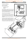
Colour coding the following colour coding, used on illustrations to denote various conditions of oil pressure and flow, is standardised throughout jcb service publications. 9803/3280 issue 1 a390940 full pressure pressure generated from operation of a service. Depending on application this may be an...
Page 4: General Information
I section 1 general information 9803/3280 section 1 i issue 2* contents page no. Machine identification plate 1 - 1 typical vehicle identification number (vin) 1 - 1 typical engine identification number 1 - 1 serial plates 1 - 2 torque settings 2 - 1 service tools numerical list 3 - 1 service tools ...
Page 5: General Information
Machine identification plate your machine has an identification plate mounted on the loader tower. The serial numbers of the machine and its major units are stamped on the plate. The serial number of each major unit is also stamped on the unit itself. If a major unit is replaced by a new one, the se...
Page 6: General Information
1 - 2 serial plates a front axle (2ws machine) b front axle (4ws machine) c rear axle (2ws machine) d rear axle (4ws machine) e synchro shuttle transmission f powershift transmission g engine section 1 general information 9803/3280 section 1 1 - 2 issue 1 e f g a s257580 a401030 s260120 b c s259100 ...
Page 7: General Information
2 - 1 torque settings use only where no torque setting is specified in the text. Values are for dry threads and may be within three per cent of the figures stated. For lubricated threads the values should be reduced by one third. Unf grade 's' bolts bolt size hexagon (a/f) torque settings in (mm) in...
Page 8: General Information
3 - 1 460/15708 flow test adapter 4 - 13 460/15707 banjo bolt 4 - 13 1406/0011 bonded washer 4 - 7 1406/0014 bonded washer 4 - 7 1406/0018 bonded washer 4 - 7, 13 1406/0021 bonded washer 4 - 6, 4 - 7 1406/0029 bonded washer 4 - 7 1604/0003 male adapter 4 - 7 1604/0004 male adapter 4 - 7, 13 1604/000...
Page 9: General Information
3 - 2 892/00282 shunt 4 - 4 892/00283 tool kit case 4 - 4 892/00284 tachometer 4 - 4 892/00285 hydraulic oil temperature probe 4 - 4 892/00286 surface temperature probe 4 - 4 892/00293 connector pipe 4 - 6 892/00294 connector pipe 4 - 6 892/00298 fluke meter 4 - 4 892/00301 flow test adapter 4 - 10 ...
Page 10: General Information
3 - 3 the following parts are replacement items for kits and would normally be included in the kit numbers quoted on pages 1/3-1 and 1/3-2. Service tools numerical list page no. Replacement item for kit no. 892/00180 892/00181 4 - 9 replacement items for kit no. 892/00253 892/00201 replacement gauge...
Page 11: General Information
Folding stand for holding glass - essential for preparing new glass prior to installation. Jcb part number - 892/00843 s186280 12v mobile oven - 1 cartridge capacity - required to pre-heat adhesive prior to use. It is fitted with a male plug (703/23201) which fits into a female socket (715/04300). J...
Page 12: General Information
'l' blades - 25 mm (1 in) cut - replacement blades for cut-out knife (above). Jcb part number - 992/12801 (unit quantity = 5 off) glass lifter - minimum 2 off - essential for glass installation, 2 required to handle large panes of glass. Ensure suction cups are protected from damage during storage. ...
Page 13: General Information
Long knife - used to give extended reach for normally inaccessible areas. Jcb part number - 892/00844 braided cutting wire - consumable heavy duty cut-out wire used with the glass extraction tool (above). Jcb part number - 892/00849 (approx 25 m length) s186330 4 - 3 section 1 general information 98...
Page 14: General Information
825/00410 15 mm crowfoot wrench 825/99833 adapter s216200 s216770 892/00882 socket for alternator pulley nut 993/85700 battery tester s239510 avo test kit 1 892/00283 tool kit case 2 892/00298 fluke meter 85 3 892/00286 surface temperature probe 4 892/00284 venture microtach digital tachometer 5 892...
Page 15: General Information
4 - 5 section 1 general information 9803/3280 section 1 4 - 5 issue 1 service tools (cont'd) section c - electrics 1 electrical repair kit 2a :7212/0002 2 way pin housing 2b :7212/0004 2 way pin retainer 2c :7212/0003 2 way socket retainer 2d :7212/0001 2 way socket connector 3a :7213/0002 3 way pin...
Page 16: General Information
Hydraulic circuit pressure test kit 892/00253 pressure test kit :892/00201 replacement gauge 0-20 bar (0-300 lbf/in 2 ) :892/00202 replacement gauge 0-40 bar (0-600 lbf/in 2 ) :892/00203 replacement gauge 0-400 bar (0-6000 lbf/in 2 ) :892/00254 replacement hose 993/69800 seal kit for 892/00254 (can ...
Page 17: General Information
Male adapters - bsp x npt (usa only) 816/00439 3/8 in. X 1/4 in. 816/00440 1/2 in. X 1/4 in. 816/15007 3/8 in. X 3/8 in. 816/15008 1/2 in. X 3/8 in. Hand pump equipment 892/00223 hand pump 892/00137 micro-bore hose 1/4 in bsp x 3 metres 892/00274 adapter 1/4 in m bsp x 3/8 in m bsp taper 892/00262 1...
Page 18: General Information
Hexagon spanners for ram pistons and end caps 992/09300 55mm a/f 992/09400 65mm a/f 992/09500 75mm a/f 992/09600 85mm a/f 992/09700 95mm a/f 992/09900 115mm a/f 992/10000 125mm a/f 4 - 8 section 1 general information 9803/3280 section 1 4 - 8 issue 1 service tools (cont'd) section e - hydraulics fem...
Page 19: General Information
S216250 892/00334 ram seal fitting tool 4 - 9 section 1 general information 9803/3280 section 1 4 - 9 issue 1 service tools (cont'd) section e - hydraulics ram seal protection sleeves 892/01016 for 25 mm rod diameter 892/01017 for 30 mm rod diameter 892/01018 for 40 mm rod diameter 892/01019 for 50 ...
Page 20: General Information
4 - 10 section 1 general information 9803/3280 section 1 4 - 10 issue 1 service tools (cont'd) section f - transmission 892/00179 bearing press (use with appropriate adapters) 992/07608 bearing adapter 992/07609 bearing adapter 992/07610 bearing adapter 992/07611 bearing adapter 992/07612 bearing ad...
Page 21: General Information
892/00224 impulse extractor set for hub bearing seals 892/00225 adapter - impulse extractor small 17mm to 25mm medium 25mm to 45mm large 45mm to 80mm 993/59500 adapter - impulse extractor (syncro shuttle and powershift transmission) s197070 4 - 11 section 1 general information 9803/3280 section 1 4 ...
Page 22: General Information
992/04800 flange spanner - for locking pinion flange while pinion nut is slackened or torque set 4 - 12 section 1 general information 9803/3280 section 1 4 - 12 issue 1 s197040 service tools (cont'd) section f - transmission 892/00182 bearing pad driver s216310 992/04000 torque multiplier (use in co...
Page 23: General Information
4 - 13 section 1 general information 9803/3280 section 1 4 - 13 issue 1 service tools (cont'd) section f - transmission 892/01077 synchro shuttle gearbox - selector shaft lock screw a395350 synchro shuttle gearbox - setting ring socket spanners a396590 a396600 892/01078 synchro shuttle gearbox - mai...
Page 24: General Information
4 - 14 section 1 general information 9803/3280 section 1 4 - 14 issue 1 service tools (cont'd) section f - transmission hydraulic circuit pressure test kit (also used for main hydraulic system tests) 892/00253 pressure test kit :892/00201 replacement gauge 0-20 bar (0-300 lbf/in 2 ) :892/00202 repla...
Page 25: General Information
4 - 15 section 1 general information 9803/3280 section 1 4 - 15 issue 1 service tools (cont'd) section f - transmission 1 6 8, 9 7 6 5 a396950 3 4 a396580 a396930 a396960 a396940 www.Workshopmanuals.Co.Uk purchased from www.Workshopmanuals.Co.Uk.
Page 26: General Information
4 - 16 section 1 general information 9803/3280 section 1 4 - 16 issue 1 service tools (cont'd) section f - transmission solid spacer setting kit synchro shuttle gearbox, sd70, sd80 axles 1 892/00918 setting tool kit 2 921/52627 spacer 14.20 service use 3 993/70111 breakback torque wrench 4 892/01076...
Page 27: General Information
4 - 17 892/01083 powershift - assembly tool, transfer gear. 892/01084 powershift - transfer gear, bearing assembly. 892/01085 powershift - seal fitting tool powershift - support plates, for use with transmission jack, manufacture locally, for details see section f, service tools. 892/01082 - powersh...
Page 28: General Information
4 - 18 section 1 general information 9803/3280 section 1 4 - 18 issue 3* * service tools (cont'd) section f - transmission a406130 d f a b c h j e g powershift gearbox - 6 speed (shiftmaster) electronic service tool kit 892/01033 kit comprises: 1 data link adaptor (dla), enables data exchange betwee...
Page 29: General Information
4 - 19 section 1 general information 9803/3280 section 1 4 - 19 issue 1 service tools (cont'd) section k - engine 892/00836 lifting wire assembly (for engine removal) s219080 892/00041 de-glazing tool for cylinder bores (to assist bedding-in of new piston rings) s192390 for details of other engine s...
Page 30: General Information
5 - 1 sealing and retaining compounds jcb multi-gasket a medium strength sealant suitable for all sizes of gasket flanges, and for hydraulic fittings of 25-65mm diameter. 4102/1212 50ml jcb high strength threadlocker a high strength locking fluid for use with threaded components. Gasketing for all s...
Page 31: Care & Safety
I section 2 care & safety 9803/3280 section 2 i issue 1 contents page no. Safety notices 1 - 1 general safety 2 - 1 operating safety 3 - 1 maintenance safety 4 - 1 www.Workshopmanuals.Co.Uk purchased from www.Workshopmanuals.Co.Uk.
Page 32: Care & Safety
1 - 1 section 2 care & safety 9803/3280 section 2 1 - 1 issue 1 safety notices in this publication and on the machine, there are safety notices. Each notice starts with a signal word. The signal word meanings are given below. ! Danger denotes an extreme hazard exists. If proper precautions are not t...
Page 33: Care & Safety
2 - 1 all construction and agricultural equipment can be hazardous. When a jcb machine is correctly operated and properly maintained, it is a safe machine to work with. But when it is carelessly operated or poorly maintained it can become a danger to you (the operator) and others. Do not work with t...
Page 34: Danger
3 - 1 operating safety ! Warning machine condition a defective machine can injure you or others. Do not operate a machine which is defective or has missing parts. Make sure the maintenance procedures in this handbook are completed before using the machine. Int-2-1-2 ! Warning controls you or others ...
Page 35: Danger
4 - 1 maintenance safety ! Warning repairs do not try to do repairs or any other type of maintenance work you do not understand. To avoid injury and/or damage get the work done by a specialist engineer. Gen-1-5 ! Warning modifications and welding non-approved modifications can cause injury and damag...
Page 36: Care & Safety
4 - 2 maintenance safety (cont'd) ! Warning diesel fuel diesel fuel is flammable; keep naked flames away from the machine. Do not smoke while refuelling the machine or working on the engine. Do not refuel with the engine running. There could be a fire and injury if you do not follow these precaution...
Page 37: Care & Safety
4 - 3 maintenance safety (cont'd) ! Warning hydraulic hoses damaged hoses can cause fatal accidents. Inspect the hoses regularly for: - damaged end fittings - chafed outer covers - ballooned outer covers - kinked or crushed hoses - embedded armouring in outer covers - displaced end fittings. Int-3-3...
Page 38: Routine Maintenance
I section 3 routine maintenance 9803/3280 section 3 i issue 1 lubricants - health and safety hygiene 2 - 1 storage 2 - 1 handling 2 - 1 first aid - oil 2 - 1 spillage 2 - 1 fires 2 - 1 service schedules 3 - 1 loader arm safety strut installing and removing 4 - 1 checking for damage 5 - 1 cleaning th...
Page 39: Routine Maintenance
Contents page no. Engine oil and filter checking the oil level 13 - 1 changing the oil and filter 13 - 1 engine cooling system checking the coolant 14 - 1 changing the coolant 14 - 1 adjusting the fan belt 14 - 2 cleaning the cab heater filter 14 - 2 fuel system types of fuel 15 - 1 fuel standards 1...
Page 40: Routine Maintenance
Iii section 3 routine maintenance 9803/3280 section 3 iii issue 1 hydraulic oil cooler cleaning the tubes/fins 23 - 1 stabiliser legs wear pads 25 - 1 wear pad adjustment 25 - 1 air conditioning adjusting the compressor drive belt 26 - 1 hose burst protection valve (if fitted) checking hose burst pr...
Page 41: Routine Maintenance
2 - 1 it is most important that you read and understand this information and the publications referred to. Make sure all your colleagues who are concerned with lubricants read it too. Hygiene jcb lubricants are not a health risk when used properly for their intended purposes. However, excessive or p...
Page 42: Routine Maintenance
3 - 1 pre-start cold checks operation 10 50 †100 500 1000 2000 service points and fluid levels hr hr hr hr hr hr engine oil level - check ! ! Oil and filter ∀ - change ! ! ! ! Air cleaner outer element # - change ! ! Air cleaner inner element - change ! Fuel filter - change ! ! ! ! Fuel filter - dra...
Page 43: Routine Maintenance
3 - 2 pre-start cold checks operation 10 50 †100 500 1000 2000 service points and fluid levels hr hr hr hr hr hr hydraulic oil cooler - clean ! ! ! Hydraulic oil strainer - clean ! Hydraulic tank filler cap (with integral filter) - change ! Hydraulic pump drive shaft - examine/grease ! ! ! ! Brakes ...
Page 44: Routine Maintenance
3 - 3 functional test operation 10 50 †100 500 1000 2000 and final inspection hr hr hr hr hr hr hydraulic speed control - operation (if fitted) - check ! ! ! ! Steer circuit pressure ∃ - check ! ! ! ! Transmission main line pressure ∃ - check ! ! ! Transmission dump operation - check ! ! ! ! Neutral...
Page 45: Routine Maintenance
4 - 1 installing install the loader arm safety strut as detailed below before working underneath raised loader arms. ! Warning raised loader arms can drop suddenly and cause serious injury. Before working under raised loader arms, fit the loader arm safety strut. 2-1-1-6 1 empty the shovel and raise...
Page 46: Routine Maintenance
5 - 1 inspect steelwork for damage. Note damaged paintwork for future repair. Make sure all pivot pins are correctly in place and secured by their locking devices. Ensure that the steps and handrails are undamaged and secure. Check for broken or cracked window glass. Replace damaged items. Check all...
Page 47: Routine Maintenance
6 - 1 park the machine on firm level ground, engage the parking brake and set the transmission to neutral. Lower the attachments to the ground and stop the engine. Clean the machine using water and/or steam. Do not allow mud, debris etc to build upon the machine, pay particular attention to the foll...
Page 48: Routine Maintenance
7 - 1 opening and closing the bonnet to release the bonnet, pull handle a , the bonnet will automatically open and be supported on gas struts. To close the bonnet, push the bonnet down, make sure it is locked in place and the side panels are located correctly. Removing and fitting a side panel ! War...
Page 49: Routine Maintenance
8 - 1 checking the seat belt condition and security ! Warning when a seat belt is fitted to your machine replace it with a new one if it is damaged, if the fabric is worn, or if the machine has been in an accident. Fit a new seat belt every three years. 2-3-1-7/1 inspect the seat belt for signs of f...
Page 50: Routine Maintenance
9 - 1 you must grease the machine regularly to keep it working efficiently. Regular greasing will also lengthen the machine's working life. The machine must always be greased after pressure washing or steam cleaning. ! Warning you will be working close into the machine for these jobs. Lower the atta...
Page 51: Routine Maintenance
9 - 2 backhoe & quickhitch 22 grease points note: figure shows a typical boom and dipper arrangement. Section 3 routine maintenance 9803/3280 section 3 9 - 2 issue 1 greasing 2 1 3 4 @ 6 £ $ ) * ^ % ¤ ( & a340900 ⁄ 8 7 9 ! 5 0 www.Workshopmanuals.Co.Uk purchased from www.Workshopmanuals.Co.Uk.
Page 52: Routine Maintenance
9 - 3 section 3 routine maintenance 9803/3280 section 3 9 - 3 issue 1 greasing front axle (4 wheel drive machines) 5 grease points front axle (2 wheel drive machines) 9 grease points 6 7 8 9 1 2 3 4 5 1 2 3 4 4 2 3 1 s260200 s260210 5 note: grease point 5 is a remote grease point mounted on the side...
Page 53: Routine Maintenance
9 - 4 section 3 routine maintenance 9803/3280 section 3 9 - 4 issue 1 greasing front axle (all wheel steer machines) 5 grease points rear axle (all wheel steer machines) 4 grease points note: grease point 5 is a remote grease point mounted on the side of the front nose (near the left front wheel). 1...
Page 54: Routine Maintenance
9 - 5 extending dipper ! Caution waxoyl contains turpentine substitute, which is inflammable. Keep flames away when applying waxoyl. Waxoyl can take a few weeks to dry completely. Keep flames away during the drying period. Do not weld near the affected area during the drying period. Take the same pr...
Page 55: Routine Maintenance
9 - 6 section 3 routine maintenance 9803/3280 section 3 9 - 6 issue 1 greasing stabilisers (centremount machines) 3 grease points on each stabiliser - total 6 grease points loader quickhitch 2 grease points each end - total 4 grease points s089961 s259390 1 2 3 4 5 6 3 2 1 6 - in - 1 clamshovel 3 gr...
Page 56: Routine Maintenance
9 - 7 section 3 routine maintenance 9803/3280 section 3 9 - 7 issue 1 greasing power sideshift total 4 grease points note: release the kingpost clamps and lower the excavator to the ground before greasing. Kingpost 9 grease points note: figure shows a centremount kingpost, greasing is same for sides...
Page 57: Routine Maintenance
9 - 8 section 3 routine maintenance 9803/3280 section 3 9 - 8 issue 1 greasing knuckle (if fitted) refer to backhoe greasing for the boom and dipper grease points. Total 2 grease points. 2 1 s256440 backhoe quickhitch (hydraulic) ! Caution waxoyl contains turpentine substitute, which is inflammable....
Page 58: Routine Maintenance
10 - 1 tyre inflation these instructions are for adding air to a tyre which is already inflated. If the tyre has lost all its air pressure, call in a qualified tyre mechanic. The tyre mechanic should use a tyre inflation cage and the correct equipment to do the job. ! Warning an exploding tyre can k...
Page 59: Routine Maintenance
11 - 1 parking brake adjustment 1 disengage the parking brake (lever horizontal). 2 turn handle grip e clockwise, half a turn. 3 test the parking brake, see section g, service procedures . 4 if the brake fails the test, repeat steps 1 , 2 and 3 . If there is no more adjustment and pin f is at the en...
Page 60: Routine Maintenance
12 - 1 changing the elements ! Caution the outer element must be renewed immediately if the warning light on the instrument panel illuminates. 2-3-3-1 note: do not attempt to wash or clean the elements - they must only be renewed. Note: do not run the engine with the dust valve j removed. Note: a ne...
Page 61: Routine Maintenance
13 - 1 checking the oil level 1 make sure the park brake is engaged and the transmission set to neutral. Lower the loader arms and backhoe to the ground, switch off the engine and remove the starter key. 2 open the bonnet, see engine panels, opening and closing the bonnet. 3 check that the oil level...
Page 62: Routine Maintenance
14 - 1 checking the coolant ! Warning the cooling system is pressurised when the coolant is hot. Hot coolant will burn you. Make sure the engine is cool before checking the coolant level or draining the system. 2-3-3-3 1 make sure the park brake is engaged and the transmission set to neutral. Lower ...
Page 63: Routine Maintenance
14 - 2 adjusting the fan belt ! Warning make sure the engine cannot be started. Disconnect the battery before doing this job. 2-3-3-5 1 park the machine on firm level ground, engage the parking brake and set the transmission to neutral. Raise and block the loader arms. Lower the backhoe to the groun...
Page 64: Routine Maintenance
15 - 1 types of fuel use good quality diesel fuel to get the correct power and performance from your engine. The recommended fuel specification for engines is given below. Cetane number: 45(minimum) viscosity: 2.5/4.5 centistokes at 40 °c (104 °f) density: 0.835/0.855 kg/litre (0.872/0.904 lb/pint) ...
Page 65: Routine Maintenance
15 - 2 filling the tank ! Warning lower the loader arms and switch off the engine before refuelling. Do not permit operation of the machine controls while refuelling. 2-3-3-9 at the end of every working day, fill the tank with the correct type of fuel. This will prevent overnight condensation from d...
Page 66: Routine Maintenance
15 - 3 draining the sediment bowl 1 park the machine on firm level ground, engage the parking brake and set the transmission to neutral. Lower the loader arms and backhoe to the ground, stop the engine. 2 look in bowl a . If it contains sediment, do steps 3 to 6. If there is water but no sediment, d...
Page 67: Routine Maintenance
16 - 1 checking the oil level 1 make sure the park brake is engaged and the transmission set to neutral. Lower the loader arms and backhoe to the ground, switch off the engine and remove the starter key. 2 open the bonnet, see engine panels, opening and closing the bonnet. 3 switch off the engine an...
Page 68: Routine Maintenance
17 - 1 checking the oil level 1 make sure the park brake is engaged and the transmission set to neutral. Lower the loader arms and backhoe to the ground, switch off the engine and remove the starter key. 2 open the bonnet, see engine panels, opening and closing the bonnet. 3 switch off the engine an...
Page 69: Routine Maintenance
17 - 2 section 3 routine maintenance 9803/3280 section 3 17 - 2 issue 1 powershift gearbox changing the oil and filter when draining jcb 760 series powershift gearboxes it is recommended that the oil is drained through the cover plate a to make sure that the debris collected in the transmission sump...
Page 70: Routine Maintenance
18 - 1 checking the fluid level ! Warning fine jets of hydraulic fluid at high pressure can penetrate the skin. Do not use your fingers to check for hydraulic fluid leaks. Do not put your face close to suspected leaks. Hold a piece of cardboard close to suspected leaks and then inspect the cardboard...
Page 71: Routine Maintenance
18 - 2 changing the filter element ! Warning fine jets of hydraulic fluid at high pressure can penetrate the skin. Do not use your fingers to check for hydraulic fluid leaks. Do not put your face close to suspected leaks. Hold a piece of cardboard close to suspected leaks and then inspect the cardbo...
Page 72: Routine Maintenance
18 - 3 changing the suction strainer ! Warning make the machine safe before getting beneath it. Lower the attachments to the ground; engage the parking brake; remove the starter key, disconnect the battery. 2-3-2-2 1 position the machine on level ground. Roll the loader shovel forward and rest it on...
Page 73: Routine Maintenance
19 - 1 checking the differential oil level ! Warning make the machine safe before getting beneath it. Lower the attachments to the ground; engage the parking brake; remove the starter key, disconnect the battery. 2-3-2-2 ! Caution the axle oil level must be checked with the machine level, otherwise ...
Page 74: Routine Maintenance
19 - 2 checking the hub oil levels check each hub separately. 1 park the machine on level ground with the oil level mark horizontal. There is a tolerance of 5 mm (0.2 in) above or below the horizontal. 2 engage the parking brake. Set the transmission to neutral. Lower the attachments to the ground. ...
Page 75: Routine Maintenance
19 - 3 the front axle procedures are the same as described on the previous pages (all wheel steer machines). Refer to the following procedures for checking and changing the oil on the rear axle. Checking the oil level ! Caution the axle oil level must be checked with the machine level, otherwise a f...
Page 76: Routine Maintenance
21 - 1 section 3 routine maintenance 9803/3280 section 3 21 - 1 issue 1 battery ! Caution do not disconnect the battery while the engine is running, otherwise the electrical circuits may be damaged. Int- 3- 1-14 ! Warning understand the electrical circuit before connecting or disconnecting an electr...
Page 77: Routine Maintenance
21 - 2 ! Warning batteries give off an explosive gas. Do not smoke when handling or working on the battery. Keep the battery away from sparks and flames. Battery electrolyte contains sulphuric acid. It can burn you if it touches your skin or eyes. Wear goggles. Handle the battery carefully to preven...
Page 78: Routine Maintenance
21 - 3 battery isolator to disconnect the battery from the machine electrics a battery isolator has been fitted. ! Caution except in an emergency, do not use the battery isolator to switch off the engine. Failure to comply may result in damage to the electrical circuits. Int-3-2-13 at the end of a w...
Page 79: Routine Maintenance
23 - 1 cleaning the tubes/fins the hydraulic oil cooler is in front of the engine radiator. If the hydraulic oil cooler tubes/fins get clogged (by dirt and flies etc) the radiator and cooler will be less efficient. 1 park the machine on firm level ground, engage the parking brake and set the transmi...
Page 80: Routine Maintenance
25 - 1 wear pads the wear pads support and guide the inner leg section. They ensure that during extension and retraction the inner leg is kept central and has a minimum amount of ‘float’. Upper wear pads a (4 off) are fitted to the top of the inner leg as shown. The upper pads are available in 3 siz...
Page 81: Routine Maintenance
26 - 1 ! Warning the air conditioning system is a closed loop system and contains pressurised refrigerant. No part of the system should be disconnected until the system has been discharged by a refrigeration engineer or a suitably trained person. You can be severely frostbitten or injured by escapin...
Page 82: Danger
27 - 1 the hose burst protection valves (if fitted) prevent the loader or backhoe falling in the event of a hose burst. These valves may be fitted on rams which raise or lower the loader arms, the boom or the dipper. Checking hose burst protection valve 1 raise the loader arms fully. Raise the boom ...
Page 83: Routine Maintenance
Item capacity fluid/lubricant international litres uk gal specification fuel tank 150 33 diesel oil astm d975-66t nos. 1d, 2d engine (oil) ! 2 wheel steer machines - build ar 11.0 2.4 jcb super multigrade 15w/40 sae15w/40 - build ak 10 2.2 -10°c to +50°c (14°f to 122°f) cf-4/sg 4 wheel steer machine...
Page 84: Routine Maintenance
Item capacity fluid/lubricant international litres uk gal specification grease points --- jcb hp grease lithium complex nlgi no.2 consistency including extreme pressure additives or jcb special mpl-ep grease % lithium based nlgi no.2 consistency including extreme pressure additives extending dipper ...
Page 85: Attachments
I section a attachments 9803/3280 section a i issue 1 contents page no. Www.Workshopmanuals.Co.Uk purchased from www.Workshopmanuals.Co.Uk.
Page 86: Body & Framework
I section b body & framework 9803/3280 section b i issue 1 contents page no. Service tools 1 - 1 slide hammer kit procedure 1 - 4 rivet nut tool procedure 1 - 5 technical data air conditioning (option) 2 - 1 basic operation air conditioning - r-134a refrigerant 3 - 1 - system operation 3 - 1 - syste...
Page 87: Body & Framework
Ii section b body & framework 9803/3280 section b ii issue 2* contents page no. Loader arms - removal and replacement 35 - 1 stabiliser legs - removal and replacement 36 - 1 kingpost - removal and replacement 37 - 1 boom & dipper - removal and replacement 38 - 1 hydraulic tank - removal and replacem...
Page 88: Body & Framework
Glass lifter - minimum 2 off - essential for glass installation, 2 required to handle large panes of glass. Ensure suction cups are protected from damage during storage. Jcb part number - 892/00842 cartridge gun - hand operated - essential for the application of sealants, polyurethane materials etc....
Page 89: Body & Framework
Wire starter - used to access braided cutting wire (below) through original polyurethane seal. Jcb part number - 892/00848 braided cutting wire - consumable heavy duty cut-out wire used with the glass extraction tool (above). Jcb part number - 892/00849 (approx 25 m length) glass extractor (handles)...
Page 90: Body & Framework
Slide hammer kit - 993/68100 1 :993/68101 slide hammer 6 :993/68106 adaptor - m20 x m24 2 :993/68102 end stops 7 :993/68107 bar - m20 x m20 x 800mm 3 :993/68103 adaptor - m20 x 5/8" unf 8 :993/68108 adaptor - m20 x 7/8" unf 4 :993/68104 adaptor - m20 x 1" unf 9 :993/68109 adaptor - m20 x m12 5 :993/...
Page 91: Body & Framework
5 fit the ' slide hammer' , item f , onto the slide bar as shown. 6 finally, fit another end stop, item c , at the end of the slide bar, as shown. The slide hammer kit is now ready to use. 7 to extract the pivot pin, slide the hammer along the bar until it contacts end stop c . Repeat this step unti...
Page 92: Body & Framework
1 - 5 rivet nut tool procedure a 'rivet nut' is a one piece fastener installed 'blind' from one side of the machine body/framework. The rivet nut is compressed so that a section of its shank forms an 'upset' against the machine body/framework, leaving a durable thread (see illustrations). Rivet nuts...
Page 93: Body And Framework
2 - 1 section b body and framework 9803/3280 section b 2 - 1 issue 1 technical data air conditioning (option) binary pressure switch settings low pressure 1.96 bar (2.0 kgf/cm 2 28.4 lbf/in 2 ) high pressure 27.5 bar (28 kgf/cm 2 400 lbf/in 2 ) thermostatic switch settings cut out -0.6 °c (33.0 °f) ...
Page 94: Body & Framework
3 - 1 section b body & framework 9803/3280 section b 3 - 1 issue 1 basic operation a401370 a b x y e h g d j f c www.Workshopmanuals.Co.Uk purchased from www.Workshopmanuals.Co.Uk.
Page 95: Body & Framework
3 - 2 section b body & framework 9803/3280 section b 3 - 2 issue 1 basic operation x d y a b c a401390 e g h j f to operate the air conditioning, press switch f to switch the system on. Press switch g to operate the 3-speed heater fan. Rotate h to select the desired temperature. Control j enables th...
Page 96: Body & Framework
3 - 3 section b body & framework 9803/3280 section b 3 - 3 issue 1 basic operation air conditioning system operation (cont'd) the refrigerant is drawn through the evaporator matrix e by the suction of the compressor. The temperature of refrigerant is now considerably below that of the air being draw...
Page 97: Body & Framework
3 - 4 7 when checking the state of the refrigerant at the receiver drier sight glass, it is necessary to run the engine with the side panel removed and the bonnet raised. Extreme care must be taken to avoid moving engine parts such as fans, pulleys and belts. 8 use caution when working near exposed ...
Page 98: Body & Framework
10 - 1 air conditioning the system will not function in very low ambient temperatures, therefore tests should be carried out in a warm environment. It is recommended that, to locate faults on the system accurately and quickly, an electronic leak detector and a refrigerant pressure gauge should be us...
Page 99: Body & Framework
10 - 2 air conditioning (cont’d) no air conditioning check action 1 are the controls set correctly, i.E. Air conditioning yes: check 2 selected, thermostat switch set to coldest position no: reset controls and retest. And blower switched on? 2 is the air conditioning (evaporator) blower working? Yes...
Page 100: Body & Framework
10 - 3 section b body & framework 9803/3280 section b 10 - 3 issue 1 fault finding a401380 c b 50 40 30 30 0 10 20 60 70 80 90 100 110 120 350 150 100 500 0 50 200 250 300 350 400 450 a air conditioning - system diagnosis this section gives an overview of the following conditions: normally functioni...
Page 101: Body & Framework
10 - 4 air conditioning - system diagnosis (cont'd) low r-134a charge gauge readings: low side gauge - low. High side gauge - low. Other symptoms: sight glass - bubbles continuously visible. Diagnosis: system slightly low on r- 134a, due to leak or incorrect charge. Correction: 1. Leak test system. ...
Page 102: Body & Framework
10 - 5 air conditioning - system diagnosis (cont'd) no refrigerant circulation gauge readings: low side gauge - zero to negative. High side gauge - low. Other symptoms: receiver-drier - frost or moisture on tubes before and after receiver-drier. Diagnosis: refrigerant flow obstructed by dirt, moistu...
Page 103: Body & Framework
10 - 6 air conditioning - system diagnosis (cont'd) air in system gauge readings: low side gauge - high. High side gauge - high. Other symptoms: sight glass - bubbles visible during system operation. Pipes - low pressure pipes are hot to the touch. Diagnosis: air is present in the system, possibly f...
Page 104: Body & Framework
10 - 7 air conditioning - system diagnosis (cont'd) compressor malfunction gauge readings: low side gauge - high. High side gauge - low. Diagnosis: internal compressor leak or compressor mechanically broken. Correction: 1. Evacuate a/c system. 2. Repair or replace compressor. 3. Charge system with r...
Page 105: Body & Framework
Air conditioning (cont'd) wiring continuity checks use the illustration below to complete continuity checks on the hvac/air conditioning system and heater harness wires.The harness connects to the main machine harness via connector 1 . Refer also to the main machine circuit diagram in section c elec...
Page 106: Body & Framework
20 - 1 checking refrigerant charge level the pressure in the system, i.E. The refrigerant charge level can be determined by checking the state of refrigerant at the receiver drier sight glass. If the level of charge is correct the sight glass will be clear. If the charge is low bubbles will be seen....
Page 107: Body & Framework
20 - 2 air conditioning - refrigerant charging and discharging note: the procedures for refrigerant charging and discharging must only be carried out by qualified service personel who have received specialist training on the air conditioning system. ! Warning the air conditioning system is a closed ...
Page 108: Body & Framework
20 - 3 air conditioning - refrigerant charging and discharging note: the procedures for refrigerant charging and discharging must only be carried out by qualified service personel who have received specialist training on the air conditioning system. ! Warning the air conditioning system is a closed ...
Page 109: Body & Framework
20 - 4 section b body & framework 9803/3280 section b 20 - 4 issue 1 service procedures electronic vacuum gauge the cps vg100 vacuum gauge is an electronic type using led’s to indicate various states of vacuum. It is used in place of or to supplement the gauge on the vacuum pump. Before connecting i...
Page 110: Body & Framework
20 - 5 air conditioning - refrigerant charging and discharging note: the procedures for refrigerant charging and discharging must only be carried out by qualified service personel who have received specialist training on the air conditioning system. ! Warning the air conditioning system is a closed ...
Page 111: Body & Framework
20 - 6 air conditioning - refrigerant charging and discharging note: the procedures for refrigerant charging and discharging must only be carried out by qualified service personel who have received specialist training on the air conditioning system. ! Warning the air conditioning system is a closed ...
Page 112: Body & Framework
20 - 7 air conditioning binary pressure switch testing the binary pressure switch assembly comprises a low pressure switch designed to open at 1.96 bar (28.4 lbf/in 2 ) and a high pressure switch designed to open at 27.5 bar (400 lbf/in 2 ) when the refrigerant pressure is within the 1.96 and 27.5 b...
Page 113: Body & Framework
20 - 8 air conditioning condenser matrix it is likely that over a period of time, because of the machine' s working environment, the airflow around the condenser matrix will become restricted due to a build up of airborne particles. If the build up of particles is severe, heat dissipation from the r...
Page 114: Body & Framework
20 - 9 air conditioning filters - changing and cleaning air intake filter 1 stop the engine and remove the starter key. 2 remove screws d , air intake cover e and filter f. Clean filter element using compressed air. Refit filter into the cover and refit. Section b body & framework 9803/3280 section ...
Page 115: Body & Framework
20 - 10 air conditioning compressor drive belt - adjusting 1 park the machine on firm level ground. Raise and block the loader arms. Lower the backhoe to the ground and stop the engine. 2 remove the starter key. ! Warning make sure the engine cannot be started. Disconnect the battery before doing th...
Page 116: Body & Framework
21 - 1 glazing the glass panes on the cab are all direct glazed. Direct glazing the following procedures explain how to correctly remove and install panes of glass that are directly bonded to the cab frame apertures. When carrying out the procedures, relevant safety precautions must be taken: 1 alwa...
Page 117: Body & Framework
21 - 2 direct glazing (cont'd) removing the broken glass and old sealant (cont'd) 1 position the machine on level ground and apply the parking brake. Stop the engine. Put protective covers over the cab seat and control pedestals. 2 a laminated glass - leave installed until the old sealant has been c...
Page 118: Body & Framework
21 - 3 direct glazing (cont'd) removing the broken glass and old sealant (cont'd) c cut-out knife f . The cut-out knife can be used as a left handed or right handed tool. For the knife and its replaceable blades, refer to service tools . (i) insert the knife blade into the sealant. (ii) make sure th...
Page 119: Body & Framework
21 - 4 direct glazing (cont'd) preparing the new glass ! Caution the laminated front screen must be handled with extra care to prevent breakage. Wherever possible, store and handle it in a vertical attitude. When placing or lifting the screen in a horizontal attitude it must be supported over its wh...
Page 120: Body & Framework
21 - 5 direct glazing (cont'd) preparing the new glass (cont'd) 5 install the ultra fast adhesive cartridge (see sealing and retaining compounds and note 2 below) into a suitable applicator gun: a remove the aluminium disc cover from the base of the cartridge and discard the 'dessicant capsule'. B m...
Page 121: Body & Framework
21 - 6 direct glazing (cont'd) installing the new glass (cont'd) 3 make the inside seal smooth: a wearing surgical gloves, dip your finger in a soapy water solution. B use your finger to make the inside seal smooth. 4 all exposed edges must be sealed using black polyurethane sealant (see sealing and...
Page 122: Body & Framework
22 - 1 cab rops/fops structure - checks ! Warning the machine is fitted with a roll over protection structure (rops) and a falling objects protection structure (fops). You could be killed or seriously injured if you operate the machine with a damaged or missing rops/fops. If the rops/fops has been i...
Page 123: Body & Framework
23 - 1 engine panels - removing and fitting instructions for removing and fitting the engine panels are described in the routine maintenance section, refer to section 3 routine maintenance - engine panels . Section b body & framework 9803/3280 section b 23 - 1 issue 1 service procedures www.Workshop...
Page 124: Body & Framework
Stabiliser leg wear pad adjustment instructions for adjusting the wear pads are described in the maintenance section, refer to section 3 stabiliser legs - wear pad adjustment . 24 - 1 section b body & framework 9803/3280 section b 24 - 1 issue 1 service procedures www.Workshopmanuals.Co.Uk purchased...
Page 125: Body And Framework
25 - 1 extending dipper - wear pad adjustment the extradig dipper wear pads are bolt-on replaceable items. They support and guide the inner dipper section during extension and retraction. The following procedures explain how to inspect, and where applicable, adjust the pads. There is a front and rea...
Page 126: Body And Framework
25 - 2 extending dipper - wear pad adjustment (cont’d) adjusting the bottom wear pads 1 park the machine on level ground. Engage the parking brake and put the transmission in neutral. 2 support the boom and dipper as shown at c . 3 stop the engine. 4 clean the sliding faces of the inner dipper with ...
Page 127: Body & Framework
26 - 1 section b body & framework 9803/3280 section b 26 - 1 issue 1 service procedures sideshift - hydraclamp clearance setting if the kingpost clearance d is not set correctly leaks may occur or the seal could become dislodged, use the procedure below to set the clearance. 1 park the machine on fi...
Page 128: Body & Framework
26 - 2 power sideshift - wear pad renewal inspection (1000 hours) when the wear pads are worn to 6 mm (0.23 in) or below they should be replaced. It is permissible to rotate the top wear pads 180° to prolong service life, provided the contact surface is more than 6 mm (0.23 in) thick. Note : if rota...
Page 129: Body & Framework
26 - 3 removal 1 park the machine on firm level ground, engage the parking brake and set the transmission to neutral. Lower the loader arms to the ground. 2 position the carriage centrally and rest the bucket on the ground, remove the starter key. 3 undo and remove nuts b . 4 remove split pins d and...
Page 130: Body & Framework
30 - 1 section b body & framework 9803/3280 section b 30 - 1 issue 1 air conditioning component key: r a/c controls s expansion valve t re-circ air inlet v water valve w hvac unit x bulkhead plate a401280 s r v x w t www.Workshopmanuals.Co.Uk purchased from www.Workshopmanuals.Co.Uk.
Page 131: Body & Framework
30 - 2 section b body & framework 9803/3280 section b 30 - 2 issue 1 air conditioning hvac/air conditioning unit - removal and replacement note: before removing the hvac/air conditioning unit, discharge the system. Refer to service procedures, air conditioning - refrigerant charging and discharging....
Page 132: Body & Framework
30 - 3 section b body & framework 9803/3280 section b 30 - 3 issue 1 air conditioning component key: r hvac unit top cover s heat exchanger (heater and evaporator) t expansion valve v freeze protection thermostat w blower unit x hvac unit housing a401270 s r t v w x www.Workshopmanuals.Co.Uk purchas...
Page 133: Body & Framework
30 - 4 section b body & framework 9803/3280 section b 30 - 4 issue 1 air conditioning blower unit - removal and replacement the blower w is located inside the hvac/air conditioning unit and can be removed without having to remove the hvac unit from the machine. The only user-serviceable part is the ...
Page 134: Body & Framework
30 - 5 component key: r a/c controls s expansion valve t re-circ air inlet v water valve w hvac unit x bulkhead plate section b body & framework 9803/3280 section b 30 - 5 issue 1 air conditioning a401280 s r v x w t www.Workshopmanuals.Co.Uk purchased from www.Workshopmanuals.Co.Uk.
Page 135: Body & Framework
30 - 6 binary pressure switch - removal and replacement the pressure switch is located adjacent to the expansion valve s on the hvac/air conditioning unit, beneath the right hand side console. ! Warning goggles and rubber gloves must be worn when pressure switches are removed or fitted. A small amou...
Page 136: Body & Framework
35 - 1 section b body & framework 9803/3280 section b 35 - 1 issue 1 loader arms a x b e g d f y z s265931 h k l t r s u www.Workshopmanuals.Co.Uk purchased from www.Workshopmanuals.Co.Uk.
Page 137: Body & Framework
35 - 2 removal and replacement removal 1 park the machine on firm level ground. Engage the parking brake and set the transmission to neutral. 2 remove loader end attachment (such as a shovel) if fitted. If the attachment is hydraulically operated, disconnect attachment hoses and plug/cap immediately...
Page 138: Body & Framework
36 - 1 section b body & framework 9803/3280 section b 36 - 1 issue 1 stabiliser legs s216810 s261790 a b e f g d c www.Workshopmanuals.Co.Uk purchased from www.Workshopmanuals.Co.Uk.
Page 139: Danger
36 - 2 removal and replacement - (centremount machines) removal 1 park the machine on firm level ground, engage the parking brake and set the transmission to neutral. Lower the backhoe and loader end to the ground and stop the engine. 2 lower the stabiliser legs to the ground. Danger hydraulic press...
Page 140: Body & Framework
36 - 3 section b body & framework 9803/3280 section b 36 - 3 issue 1 stabiliser legs s271850 a b c www.Workshopmanuals.Co.Uk purchased from www.Workshopmanuals.Co.Uk.
Page 141: Body & Framework
36 - 4 removal and replacement - (sideshift machines) removal 1 park the machine on firm level ground. Engage the parking brake and set the transmission to neutral. 2 lower the loader shovel to the ground. 3 make sure that the backhoe assembly is set central to the mainframe as shown. If necessary '...
Page 142: Body & Framework
37 - 1 section b body & framework 9803/3280 section b 37 - 1 issue 1 kingpost s254893 a252880 a252870 a261800 removal and replacement 1 3 2 4 5 6 7 8 9 10 13 13 15 15 14 14 16 16 m 14 om pivot bearing - 15ft 6in / 17ft backhoe) 80 65 72 71 item 14 (boom pivot bearing - 14ft backhoe) item 15 (kingpos...
Page 143: Body & Framework
37 - 2 removal and replacement removal 1 slew the kingpost to the centre and remove the boom and dipper. ! Warning hydraulic fluid at system pressure can injure you. Before disconnecting or connecting hydraulic hoses, stop the engine and operate the controls to release pressure trapped in the hoses....
Page 144: Body & Framework
38 - 1 section b body & framework 9803/3280 section b 38 - 1 issue 1 boom and dipper a b d c f g l h j e www.Workshopmanuals.Co.Uk purchased from www.Workshopmanuals.Co.Uk.
Page 145: Danger
38 - 2 boom - removal and replacement removal the procedures describe the removal of the boom with the boom and dipper rams still installed. If required, these items can be removed separately before removing the boom, refer to the appropriate removal and replacement procedure. 1 remove the backhoe b...
Page 146: Body & Framework
38 - 3 section b body & framework 9803/3280 section b 38 - 3 issue 1 boom and dipper b a c d e f g h j k l s266170 www.Workshopmanuals.Co.Uk purchased from www.Workshopmanuals.Co.Uk.
Page 147: Danger
38 - 4 dipper - removal and replacement removal the procedures describe the removal of the dipper with the extradig (if fitted) and the bucket ram still installed. If required, these items can be removed separately before removing the dipper, refer to the appropriate removal and replacement procedur...
Page 148: Body & Framework
39 - 1 removal and replacement removal ! Warning make the machine safe before working underneath it. Park the machine on level ground, lower the arms. Apply the parking brake, put the transmission in neutral and stop the engine. Chock both sides of all four wheels. Disconnect the battery, to prevent...
Page 149: Body & Framework
40 - 1 removal and replacement removal 1 park the machine on firm level ground, engage the parking brake and set the transmission to neutral. Lower the loader arms to the ground. 2 position the carriage in the central protruding travel position at 150 mm (6 in) from end of the rail, rest the bucket ...
Page 150: Body and Framework
50 - 1 section b body and framework 9803/3280 section b 50 - 1 issue 1 cab panels removal and replacement side console removal 1 park the machine on firm level ground, apply the parking brake. Lower the loader arms and excavator to the ground, switch off the engine and remove the starter key. 2 disc...
Page 151: Body and Framework
51 - 1 section b body and framework 9803/3280 section b 51 - 1 issue 1 cab panels removal and replacement front/steering console removal 1 park the machine on firm level ground, apply the parking brake. Lower the loader arms and excavator to the ground, switch off the engine and remove the starter k...
Page 152: Electrics
Service tools 1 - 1 technical data system type 2 - 1 battery 2 - 1 alternator 2 - 1 fuses & relays 2 - 2 fuse link box 2 - 3 relays 2 - 3 basic system operation circuit schematics basic machine - 3cx, 4cx, 214, 215, 217 (not 214e) 4 - 1 synchro shuttle and powershift 4 - 5 options - steer mode (4x4x...
Page 153: Electrics
Ii section c electrics 9803/3280 section c ii issue 3* contents page no. Alternator removal and replacement 30 - 1 starter motor removal and replacement 40 - 2 inspection 40 - 2 dismantling and assembly 40 - 2 earth points 145 - 1 harness data drawings 150 - 1 harness interconnection 150 - 1 * www.W...
Page 154: Electrics
993/85700 battery tester avo test kit 1 892/00283 tool kit case 2 892/00298 fluke meter 85 3 892/00286 surface temperature probe 4 892/00284 venture microtach digital tachometer 5 892/00282 100 amp shunt - open type 6 892/00285 hydraulic temperature probe 825/00410 15 mm crowfoot wrench 825/99833 ad...
Page 155: Electrics
2 - 1 general electrical data system type 12 volt, negative earth battery (heavy duty) - cold crank amps for 1 minute to 1.4 volts per cell at -18 deg c (0 deg f) 550 - reserve capacity (minutes) for 25 amp load 220 battery (temperate) - cold crank amps for 1 minute to 1.4 volts per cell at -18 deg ...
Page 156: Electrics
2 - 2 fuses and relays fuses ! Caution always replace fuses with ones of correct ampere rating to avoid electrical system damage. 8-3-3-5 the relays and fuses are located in the side console underneath cover a . If a fuse melts, find out why and rectify the fault before fitting a new one. The fuses ...
Page 157: Electrics
2 - 2 fuses and relays fuses ! Caution always replace fuses with ones of correct ampere rating to avoid electrical system damage. 8-3-3-5 the relays and fuses are located in the side console underneath cover a . If a fuse melts, find out why and rectify the fault before fitting a new one. The fuses ...
Page 158: Electrics
Electrics technical data section c section c 9803/3280 issue 3* 2 - 3 2 - 3 relays 4 speed powershift / synchro shuttle the relays listed below are located in the side console underneath cover a . 1 ignition 1 2 hammer 3 auxiliary (jaw bucket) 4 main lights 5 engine run 6 hydraulic speed control (hs...
Page 159: Electrics
Electrics basic system operation section c section c 9803/3280 issue 3* 4 - 1 4 - 1 r a d io 861 h a za r d w a r n in g fr o n t w/l tu r n s ig n a l front console instruments w a te r te m p s e n d e r 18 - p r im a r y fu s e 3 tr a n s o il p r e s e .S .O .S . 10 a l te r n a t o r w a te r t...
Page 160: Electrics
4 - 2 main components: 1 thermostart 2 battery isolator 3 battery 4 starter switch 5 neutral start relay 6 starter solenoid 7 starter motor 8 alternator 9 cold start advance solenoid 10 cold start advance switch 11 engine shut-off solenoid (esos) 12 ignition relay ‘1’ 13 ignition relay ‘2’ 14 rear h...
Page 161: Electrics
4 - 3 main components: 59 cigar lighter 60 face level fan 61 face level fan switch 62 heated seat 63 heated seat switch 64 rear washer/wiper switch 65 rear wiper motor 66 rear washer motor 67 front washer/wiper switch 68 front washer motor 69 front wiper intermittent electronic control unit 70 front...
Page 162: Electrics
Electrics basic system operation section c section c 9803/3280 issue 3* 4 - 4 4 - 4 b e a c o n s witc h 11 0 10 7 814 839 2 fu s e c 10 r e a r w a s h e r p u m p fu s e b 5 4 m 2 4 11 7 lig h t s witc h 2 3 h e a te r 001 837 f/w/l s witc h m fu s e b 10 fu s e c 9 fr o n t w a s h e r p u m p 86...
Page 163: Electrics
3 6 10 fo r / r e v 7 9 4 3 2 fo r / r e v s witc h tr a n s d u mp r e la y 1 f r 812 1 2 n 4 to fuse a5 mission & steer mode options 10 2 7 5 tr a n s m is s io n e a r th 5 r e v e r s e a la r m 8 8 1 m a in s h a ft s o le n o id 850 fo r w a r d h ig h s o le n o id d u m p s witc h (lo a d e ...
Page 164: Electrics
4 - 6 circuit schematic - synchro shuttle and powershift synchro shuttle transmission 1 parking brake warning light relay 2 parking brake relay 3 parking brake switch 4 transmission dump relay 5 transmission dump switch on loader lever 6 transmission dump switch on gear lever 7 forward solenoid 8 fo...
Page 165: Electrics
4 - 7 circuit schematics - options steer mode - 4cx and 3cx super (4x4x4) 1 front axle proximity switch 2 rear axle proximity switch 3 steer mode selector switch 4 steer mode printed circuit board 5 crab relay 6 crab/4 wheel steer relay 7 2 wheel steer relay 8 4 wheel steer relay 9 4 wheel steer/cra...
Page 166: Electrics
A u t o 2w d r e la y 4 w b r e la y 4w d /4w b fu s e a 5 126 2w d /4w b 8 4w d /4w b 2w d s o le n o id b r m o d e s w a u t o 2wd r e la y 2 6 b r a k e lig h ts s witc h 4wb r e la y 858 10 r h b r a k e lig h t 7 933 854 5 4 877 3 107 1 853 lh b r a k e lig h t 816 fu s e a 8 1 2 3 4 5 6 7 fu ...
Page 167: Electrics
854 933 8 4wd s witc h 1 2 3 4 4wd s o le n o id 9 6 6 illu m in a tio n 922 101 107 829 816 830 5 3 7 10 a u t o 2wd r e la y r h b r a k e lig h t 107 4wb r e la y 4th s p e e d p /s h ift fe e d lh b r a k e lig h t a u t o 2wd r e la y 858 7 5 877 b r a k e lig h ts s witc h 974 illu m in a tio ...
Page 168: Electrics
4 - 10 circuit schematics - options all wheel steer/brake mode 1 lh brake light 2 rh brake light 3 brake light switch 4 4 wheel braking relay 5 4 wheel drive solenoid 6 auto 2 wheel drive relay 7 4 wheel drive selector switch connections: j from j on page c/4-4 s from 14 on page c/4-5 and 9 on c/4-1...
Page 169: Electrics
4 - 11 circuit schematics - options hand held tools 1 selector switch 2 indicator lamp 3 roadbreaker solenoid dedicated quickhitch 1 hitch enable switch 2 quick-hitch relay 3 warning buzzer 4 lever ‘hold-in’ button 5 lever ‘hold-in’ button 6 quick-hitch solenoid pole planter 1 selector switch 2 grab...
Page 170: Electrics
Electrics basic system operation section c section c 9803/3280 issue 2* 4 - 12 4 - 12 circuit schematics - options hand held tools dedicated quick-hitch pole planter q u ic k -h itc h fe e d s witc h q u ic k -h itc h r e la y fu s e a 1 1874 r o t a tio n s o le n o id g r a b s o le n o id d e d i...
Page 171: Electrics
Electrics basic system operation section c section c 9803/3280 issue 2* 4 - 13 4 - 13 10 7 106 922 8 6 p a r k b r a k e r e la y 10 n e u tr a l s ta r t r e la y 6 7 from parkbrake warning light 3rd g e a r 120 ohm resistor r e v e r s e a la r m r e la y d ia g n o s tic s p /b r a k e s witc h 1...
Page 172: Electrics
4 - 14 circuit schematic - 6 speed powershift (shiftmaster) 6 speed powershift transmission 1 parking brake warning light relay 2 parking brake relay 3 parking brake switch 4 reverse alarm 5 reverse alarm relay 6 speed sensor 7 electronic control unit 8 forward/reverse selector lever 9 gear selector...
Page 173: Electrics
4 - 15 section c electrics 9803/3280 section c 4 - 15 issue 1 basic system operation main components: 1 thermostart 2 battery 3 starter switch 4 neutral start relay 5 starter solenoid 6 starter motor 7 ignition relay ‘1’ 8 transmission dump relay 9 forward/reverse selector lever 10 forward relay 11 ...
Page 174: Electrics
Electrics basic system operation section c section c 9803/3280 issue 1 4 - 16 4 - 16 front wiper for / rev switch c2 107 neutral st ar t rela y for w ard rela y fuse b2 110 reverse alarm 814 809 862 flasher unit 412 u fuse c8 front horn switch dump switch (loader) 17 7 408 st ar ter motor 401 18 hea...
Page 175: Electrics
Electrics basic system operation section c section c 9803/3280 issue 1 4 - 17 4 - 17 8 011 401 402 engine oil pres s tr o b e li g h t s k t ha nd b ra ke 830 tr a ns o il t em p s wi tch fuse c6 2 861 2 a ir fi lt er f/ w/ l s wi tch 4 106 412 011 7 7 116 405 r /w/ l s wi tch a lt erna tor fuse b1 ...
Page 176: Electrics
4 - 18 section c electrics 9803/3280 section c 4 - 18 issue 1 basic system operation main components: 57 alternator warning indicator light 58 parking brake indicator light 59 engine coolant temperature indicator light 60 engine coolant temperature switch 61 transmission oil temperature indicator li...
Page 177: Electrics
19 - 1 electrical testing methods - using a multimeter these instructions are intended to cover the use of the recommended multimeters. 1 make sure that the test leads are plugged into the correct sockets. The black test lead should be plugged into the black socket (sometimes, this socket is also ma...
Page 178: Electrics
19 - 2 section c electrics 9803/3280 section c 19 - 2 issue 1 service procedures s153070 www.Workshopmanuals.Co.Uk purchased from www.Workshopmanuals.Co.Uk.
Page 179: Electrics
19 - 3 electrical testing methods - using a multimeter 1 measuring dc voltage a on the fluke 85 turn the switch to position b . B on the av0 2003 move the right slider switch to position a , and the left hand slider switch to the appropriate range. C on an analogue meter turn the dial to the appropr...
Page 180: Electrics
19 - 4 section c electrics 9803/3280 section c 19 - 4 issue 1 service procedures www.Workshopmanuals.Co.Uk purchased from www.Workshopmanuals.Co.Uk.
Page 181: Electrics
19 - 5 electrical testing methods - using a multimeter 4 testing a diode or a diode wire a diode wire is a diode with male connector fitted on one end and a female connector fitted on the other end. The diode is sealed in heatshrink sleeving. A on the fluke 85 turn the switch to position d . Press t...
Page 182: Electrics
20 - 1 safety ! Warning batteries give off an explosive gas. Do not smoke when handling or working on the battery. Keep the battery away from sparks and flames. Battery electrolyte contains sulphuric acid. It can burn you if it touches your skin or eyes. Wear goggles. Handle the battery carefully to...
Page 183: Electrics
20 - 2 section c electrics 9803/3280 section c 20 - 2 issue 1 service procedures battery (cont’d) testing this test is to determine the electrical condition of the battery and to give an indication of the remaining useful ‘life’. Before testing ensure that the battery is at least 75% charged (sg of ...
Page 184: Electrics
21 - 1 alternator general description the alternator is a three phase generator having a rotating field winding and static power windings. When the start switch is turned on, current from the battery flows by way of the 'no charge' warning light to the field winding. This creates a magnetic field wh...
Page 185: Electrics
Starter motor starting circuit test before carrying out the voltmeter tests, check the battery condition (see battery testing) and ensure that all connections are clean and tight. To prevent the engine starting during the tests ensure that the engine stop fuse is removed, (refer to fuse identificati...
Page 186: Electrics
22 - 2 starter motor (cont’d) starting circuit test (cont'd) test 3b if the reading between terminal d and earth is below 8.0v, connect the voltmeter between terminal e and earth. An increase in the reading to 8.0v indicates either a faulty start relay or a fault in the feed from the transmission se...
Page 187: Electrics
23 - 1 wiring harness introduction instances do occur where it is necessary to incorporate auxiliary electrical components into existing electrical circuits and, although unlikely with present wiring harnesses, repair or replace specific individual wires within a harness. This will also apply to oth...
Page 188: Electrics
With the butane heater assembly 892/00350, seal the connection using the following procedure. A remove the cap a from the end of the disposable gas cartridge b . B before assembling the gas cartridge to the reflector element c , turn the red ring d to the left, (in the direction of the minus sign ma...
Page 189: Electrics
E turn the red ring d to the right (in the direction of the plus sign) in order to turn on the gas. Important: before turning the heater on, make sure that the cartridge is not hotter than the reflector element. This may occur if the cartridge is held in the hand for a long time. The temperature dif...
Page 190: Electrics
30 - 1 removal and replacement disconnect cables from rear of alternator, remove bolts a , b and c and withdraw unit from machine. Replace by reversing the removal sequence. Position the alternator until belt deflection is approximately 10mm (3/8 in) before tightening bolts b and c . It may be neces...
Page 191: Electrics
40 - 1 section c electrics 9803/3280 section c 40 - 1 issue 1 starter motor s02043c www.Workshopmanuals.Co.Uk purchased from www.Workshopmanuals.Co.Uk.
Page 192: Electrics
40 - 2 removal and replacement disconnect cables and remove battery. Remove cables from main starter terminal and solenoid terminal. Using special tool 825/00410 (and adapter 825/99833 if required) unscrew three securing nuts and remove starter motor. Replace by reversing the removal sequence. Disma...
Page 193: Electrics
145 - 1 earth points section c electrics 9803/3280 section c 145 - 1 issue 1 harness data a405010 dr2 e2 mb f f1 f2 f nj e a c47 e f a e1 e g fb1 h dr2 www.Workshopmanuals.Co.Uk purchased from www.Workshopmanuals.Co.Uk.
Page 194: Electrics
145 - 2 earth points introduction the illustartion opposite shows the machine electrical earth point locations. This can be useful when tracing electrical faults, typically when several electrical devices are malfunctioning. † the illustration opposite shows the battery earth cable connection for ma...
Page 195: Electrics
Harness interconnection the harness number refers to and corresponds with the annotations in the schematic drawing on the adjacent page. Harness no. Issue remarks page 1 front console 721/10940 1 4 speed powershift / synchro shuttle 151 - 1 721/10937 3 6 speed powershift (shiftmaster) 151 - 3 2 side...
Page 196: Electrics
Electrics harness data section c section c 9803/3280 issue 1 150 - 2 150 - 2 2 4 3 8 7 ca nh c10† cs cp n g b s me c10 c10 la c40 cr lc fa la lb cb 1 6 5 10 11 9 a408780 harness interconnection (continued) side console harness - main components connected to this harness: side console instruments sid...
Page 197: Electrics
Electrics harness data section c section c 9803/3280 issue 2* 151 - 1 151 - 1 721/10940_1 key to connectors: fa bulkhead plug fb front cab earth fc steer mode unit fd forward relay forward h.L fe reverse relay reverse h/l ff drive relay interlock relay fg transmission dump blank fh 4ws auto 2wd fj l...
Page 198: Electrics
Electrics harness data section c section c 9803/3280 issue 2* 151 - 2 151 - 2 harness drawing - front console, 4 speed powershift, synchro shuttle, page 2 of 2 - cad 721/10940 issue 1 853g 0.6 sm fsa 107/922 wipermotor 805d - - 0.6 11 835c sd 6 ft 6 fa 16 54 5 dest 1.0 0.6 2 8 - 0.6 sd ff1 14 dest 2...
Page 199: Electrics
Electrics electrics harness data harness data section c section c 9803/3280 issue 1 151 - 3 151 - 3 a721/10937_1 harness drawing - front console, 6 speed powershift (shiftmaster) page 1 of 2 - cad 721/10937 issue 1 key to connectors: fa bulkhead plug fb front cab earth fc steer mode unit fg transmis...
Page 200: Electrics
Electrics electrics harness data harness data section c section c 9803/3280 issue 1 151 - 4 151 - 4 1.0 ft 5 af,ag type type 845 8 fy 823 u 830av wire 1.0 sb ft 6 826b 1.0 fc dest dest sa 2 1.0 600l af,ag 4 821 af,ag 5 sr 0.6 wire steermodeunit 8 ap 825d d,e 1 af,ag 3 0.6 2 835 size ap 868 600n fa 4...
Page 201: Electrics
Electrics harness data section c section c 9803/3280 issue 2* 153 - 1 153 - 1 721/10936_1 harness drawing - side console, page 1 of 4 * - cad 721/10936 issue 1 (machines up to serial no. 933756) www.Workshopmanuals.Co.Uk purchased from www.Workshopmanuals.Co.Uk.
Page 202: Electrics
Electrics electrics harness data harness data section c section c 9803/3280 issue 2* 153 - 2 153 - 2 harness drawing - side console, page 2 of 4 * - cad 721/10936 issue 1 (machines up to serial no. 933756) key to connectors: ca mainframe plug cb cab link cca fuse box a ccb fuse box b ccc fuse box c ...
Page 203: Electrics
Electrics electrics harness data section c section c 9803/3280 issue 2* 153 - 3 153 - 3 721/10936_3 harness drawing - side console, page 3 of 4 - cad 721/10936 issue 1 (machines up to serial no. 933756) www.Workshopmanuals.Co.Uk purchased from www.Workshopmanuals.Co.Uk.
Page 204: Electrics
Electrics electrics harness data harness data section c section c 9803/3280 issue 2* 153 - 4 153 - 4 721/10936_4 harness drawing - side console, page 4 of 4 - cad 721/10936 issue 1 (machines up to serial no. 933756) www.Workshopmanuals.Co.Uk purchased from www.Workshopmanuals.Co.Uk.
Page 205: Electrics
Electrics electrics harness data harness data section c section c 9803/3280 issue 1 153 - 5 153 - 5 721/10970_1 harness drawing - side console, page 1 of 5 - cad 721/10970 issue 2 (machines from serial no. 933757) www.Workshopmanuals.Co.Uk purchased from www.Workshopmanuals.Co.Uk.
Page 206: Electrics
Harness drawing - side console, page 2 of 5 - cad 721/10970 issue 2 (machines from serial no. 933757) 153 - 6 section c electrics 9803/3280 section c 153 - 6 issue 1 harness data key to connectors: ca main frame plug cca fusebox a ccb fusebox b ccc fusebox c cd ignition 1 ce ignition 2 cf start inhi...
Page 207: Electrics
Harness drawing - side console, page 3 of 5 - cad 721/10970 issue 2 (machines from serial no. 933757) 153 - 7 section c electrics 9803/3280 section c 153 - 7 issue 1 harness data key to connectors: cb cab link cu ignition switch (cu1) cv instrument panel cw fuel gauge cwa fuel gauge illium cx water ...
Page 208: Electrics
Electrics electrics harness data harness data section c section c 9803/3280 issue 1 153 - 8 153 - 8 721/10970_2 harness drawing - side console, page 4 of 5 - cad 721/10970 issue 2 (machines from serial no. 933757) www.Workshopmanuals.Co.Uk purchased from www.Workshopmanuals.Co.Uk.
Page 209: Electrics
Electrics electrics har ness data har ness data section c section c 9803/3280 issue 1 153 - 9 153 - 9 7 2 1 /1 0 9 7 0 _ 3 har ness drawing - side console, page 5 of 5 - cad 721/10970 issue 2 (machines from serial no. 933757) www.Workshopmanuals.Co.Uk purchased from www.Workshopmanuals.Co.Uk.
Page 210: Tri
155 - 1 s e c tio n c e le c tri c s 9803/ 3280 s e c tio n c 155 - 1 issue 1 ha rne ss d a ta harness drawing - cab roof (usa only) page 1 of 2 - cad 721/10966 issue 1 721/10966_1 www.Workshopmanuals.Co.Uk purchased from www.Workshopmanuals.Co.Uk.
Page 211: Tri
155 - 2 s e c tio n c e le c tri c s 9803/ 3280 s e c tio n c 155 - 2 issue 1 ha rne ss d a ta harness drawing - cab roof (usa only) page 2 of 2 - cad 721/10966 issue 1 721/10966_2 key to connectors: c5 lh worklight c10 beacon socket c15 lh front indicators c20 rh worklight c25 lh headlights c30 rh ...
Page 212: Tri
155 - 3 s e c tio n c e le c tri c s 9803/ 3280 s e c tio n c 155 - 3 issue 1 ha rne ss d a ta harness drawing - cab roof (not usa) page 1 of 2 - cad 721/10965 issue 1 200 2500 10 600 350 1375 2575 lh headlights 300 1175 s5 12 lh worklight 60 s15 s22 rh worklight c80 aux beacon socket earth 250 c55 ...
Page 213: Tri
155 - 4 s e c tio n c e le c tri c s 9803/ 3280 s e c tio n c 155 - 4 issue 1 ha rne ss d a ta harness drawing - cab roof (not usa) page 2 of 2 - cad 721/10965 issue 1 c30 5 c40 8 c25 1 721/10965_2 key to connectors: c5 lh worklight c10 beacon socket c20 rh worklight c25 lh headlights c30 rh headlig...
Page 214: Electrics
Harness drawing - interior light, radio speakers page 1 of 1 - cad 721/11050 issue 1 155 - 5 section c electrics 9803/3280 section c 155 - 5 issue 1 har ness data g,h 100 0.6 601 g,h 2 term term ls cp 5 cp 5 g,h dest e,f 2 859 dest - wire type 1 wire 1 rs cp 6 cp 6 type 0.6 size cp 3 cp 3 e,f rh spe...
Page 215: Tri
157 - 1 s e c tio n c e le c tri c s 9803/ 3280 s e c tio n c 157 - 1 issue 1 ha rne ss d a ta harness drawing - steer controls, page 1 of 1- cad 721/10968 issue 1 721/10968_1 key to connectors: ma 2ws md 4ws me cab connector mf rear proximity switch sa steer mode feed sm steer mode feed www.Worksho...
Page 216: Tri
157 - 2 s e c tio n c e le c tri c s 9803/ 3280 s e c tio n c 157 - 2 issue 1 ha rne ss d a ta harness drawing - steer controls, page 1 of 1 - cad 721/10967 issue 1 1.0 1.0 dest da 721/10967_1 key to connectors: ma 2ws mb 4ws com mc crab md 4ws me cab connector mf rear proximity switch sa steer mode...
Page 217: Tri
160 - 1 s e c tio n c e le c tri c s 9803/ 3280 s e c tio n c 160 - 1 issue 1 ha rne ss d a ta harness drawing - transmission, page 1 of 2 - cad 721/10943 issue 1 37 49 13 721/10943_1 key to connectors: la front console harness lb side console harness lc gearbox ld transmission oil temperature switc...
Page 218: Tri
160 - 2 s e c tio n c e le c tri c s 9803/ 3280 s e c tio n c 160 - 2 issue 1 ha rne ss d a ta harness drawing - transmission, page 2 of 2 - cad 721/10943 issue 1 721/10943_2 www.Workshopmanuals.Co.Uk purchased from www.Workshopmanuals.Co.Uk.
Page 219: Tri
160 - 3 s e c tio n c e le c tri c s 9803/ 3280 s e c tio n c 160 - 3 issue 1 ha rne ss d a ta harness drawing - transmission, page 1 of 2 - cad 721/10942 issue 1 36 60 48 31 37 49 25 13 30 24 12 36 60 48 37 49 13 30 24 12 13mm wide (nom) red tape (2 posn) front console harness side console harness ...
Page 220: Tri
160 - 4 s e c tio n c e le c tri c s 9803/ 3280 s e c tio n c 160 - 4 issue 1 ha rne ss d a ta harness drawing - transmission, page 2 of 2 - cad 721/10942 issue 1 www.Workshopmanuals.Co.Uk purchased from www.Workshopmanuals.Co.Uk.
Page 221: Tri
160 - 5 s e c tio n c e le c tri c s 9803/ 3280 s e c tio n c 160 - 5 issue 1 ha rne ss d a ta harness drawing - transmission, page 1 of 2 - cad 721/10941 issue 1 solenoid identification hsg id function id char c20 forward high c30 forward low c40 mainshaft c50 layshft c60 reverse low c70 reverse hi...
Page 222: Electrics
Harness drawing - transmission - * powershift 6 speed, page 2 of 2 - cad 721/10941 issue 1 1864 size 1863 1.0 107ak c80 1.0 reverse high 1.0 term 2.0 wire c10 10 type 11 1 600by term c,d h 1.0 term term c50 sa 2 c15 1 type 1 h 1.0 wire h 600bt term 2 600hv dest h 1.0 c60 type 600hv 1.0 reverse low 4...
Page 223: Electrics
Harness drawing - transmission - sychro shuttle, page 1 of 1 - cad 721/10938 issue 2 * 1.0 dest ga 4 c dest 1.0 ga 3 reverse solenoid type gc 1.0 term sa 2 600bt wire 811 size 1 type forward solenoid type size 1.0 405 gb d e,f wire 1.0 600bu xmsn oil press sw gf 2 1.0 wire 812 term 600bu c 600bs a s...
Page 224: Electrics
160 - 8 section c electrics 9803/3280 section c 160 - 8 issue 1 har ness data harness drawing - transmission - powershift 4 speed, page 1 of 1 - cad 721/10939 issue 1 - size 849 1.0 c80 1.0 reversehigh 1.0 term 2.0 wire c1010 type 11 11 1 600by term c,d h 1.0 term term c50 sa 2 c151 type 1 j 1.0 h 6...
Page 225: Electrics
Harness drawing - engine mainframe, page 1 of 2 - cad 721/10935 issue 2 * 721/10935_1 165 - 1 section c electrics 9803/3280 section c 165 - 1 issue 2* har ness data www.Workshopmanuals.Co.Uk purchased from www.Workshopmanuals.Co.Uk.
Page 226: Electrics
Harness drawing - engine mainframe, page 2 of 2 - cad 721/10935 issue 2 * 1.0 ma 2 ba 4.0 - 1.0 u 40 term 617 24 513 44 - e,f 1851 1.0 43 - 33 bf p 200b 4 1.0 ba 1.0 - 11 1.0 1 15 bf 19 nk a 8 5 1.0 21 903 nf a nc 3 type a 13 a,an bf my a my b nc 1 1.0 38 23 10 mr 1 4.0 105 863 600bk ba ms 1 1801 - ...
Page 227: Electrics
Harness drawing - rear lights / hydraclamp - sideshift, page 1 of 1 - cad 721/10944 issue 1 721/19044 key to connectors: la cab plug lb hydraclamp lc rh rear lights ld lh rear lights sa earth sb brake lights 165 - 3 section c electrics 9803/3280 section c 165 - 3 issue 2* har ness data * www.Worksho...
Page 228: Electrics
165 - 4 section c electrics 9803/3280 section c 165 - 4 issue 1 har ness data harness drawing - rear horn / alarm - sideshift, page 1 of 1 - cad 721/10946 issue 1 1 size 847a wire c,d 600cd 2 s10 term 1.0 a,b c50 type reverse alarm reverse alarm c103 c,d dest 1.0 1 size 835 wire c,d 600bj 2 s10 term...
Page 229: Electrics
165 - 5 section c electrics 9803/3280 section c 165 - 5 issue 1 har ness data harness drawing - rear horn / alarm - centre mount page 1 of 1 - cad 721/10947 issue 1 1 size 847a wire c,d 600cd 2 s10 term 1.0 a,b c50 type reverse alarm reverse alarm c103 c,d dest 1.0 1 size 835 wire c,d 600bj 2 s10 te...
Page 230: Electrics
165 - 6 section c electrics 9803/3280 section c 165 - 6 issue 1 har ness data harness drawing - auxiliary - excavator page 1 of 1 - cad 721/10974 issue 1 1100 1 size 101aa wire k,l 899 2 c106 term 1.0 a,b c50 type microswitch s10 k,l dest 1.0 1 size 874c wire k,l 600cx 2 s20 term 1.0 a,b c40 type ja...
Page 231: Controls
Contents page no. Steering column removal and replacement 30 - 1 dismantling and assembly 30 - 1 shovel reset (214e machines) 31 - 1 return to dig operation 33 - 1 adjustment 33 - 1 precision control (servo) machines up to serial no. 931159 basic system operation - component location 35 - 1 - compon...
Page 232: Controls
Ii section d controls 9803/3280 section d ii issue 1 contents page no. Precision control (servo) machines from january 2003 (continued) servo pressure supply valve - removal and replacement 51 - 1 - dismantling and assembly 51 - 2 control rods and linkages dismantling and assembly - loader valve con...
Page 233: Controls
A396921 30 - 1 section d controls 9803/3280 section d 30 - 1 issue 2* steering column g a b r d n c h c b l f f b b e j h h m p t g s h www.Workshopmanuals.Co.Uk purchased from www.Workshopmanuals.Co.Uk.
Page 234: Controls
30 - 2 removal and replacement the steering column can be tilted to improve operator reach and comfort levels. This type of assembly is refered to as a ‘tilt column’. The illustration on the adjacent page is intended as a guide to removal and replacement. Removal 1 park the machine on firm level gro...
Page 235: Controls
2065mm a320510 31 - 1 section d controls 9803/3280 section d 31 - 1 issue 1 shovel reset h e b g f h a j l m k c www.Workshopmanuals.Co.Uk purchased from www.Workshopmanuals.Co.Uk.
Page 236: Controls
31 - 2 214e machines only the shovel reset system is designed to automatically tilt the shovel forward when the loader arms are raised, this prevents a heaped shovel from depositing its contents over the back of the shovel onto the bonnet or cab when the loader arms are raised. When the loader arms ...
Page 237: Controls
33 - 1 section d controls 9803/3280 section d 33 - 1 issue 1 return to dig a374040 1 2 x www.Workshopmanuals.Co.Uk purchased from www.Workshopmanuals.Co.Uk.
Page 238: Controls
33 - 2 operation this enables you to roll the shovel from the rolled forward position into the digging position quickly and easily. When you select ‘return to dig’ a proximity switch on one of the loader arms cuts off the hydraulic pressure to the shovel rams immediately the shovel reaches the corre...
Page 239: Controls
35 - 1 section d controls 9803/3280 section d 35 - 1 issue 1 precision control (servo) a402030 v p r h p g f s j m u k a c l s e q d t n u u u u b basic system operation component location www.Workshopmanuals.Co.Uk purchased from www.Workshopmanuals.Co.Uk.
Page 240: Controls
35 - 2 basic system operation component identification a right hand joystick b left hand joystick c operator seat d pilot supply valve e supply valve solenoid f oil filter access plug g accumulator h right hand pilot control valve j left hand pilot control valve k seat mounted micro switch l joystic...
Page 241: Controls
Full pressure servo exhaust key to oil flow & pressure 1h 3h 3h 4j 4h 4 1 4 2 pl pr tr tl tp t p 3 1 2 3 p t p t 2h 2j 2j 1h s1b s2b s3b s4b s3b s2b s2a iso + sae + sae + s3a s1a s2a s3a s4a 4j 1j 3j h h j j a n g b d d z q l k r f e a402070 m t 4 t p 1 2 3 q e g f s tp pl p tr tl pr t tl 2 t p 3 4 ...
Page 242: Controls
35 - 4 basic system operation component key: a right hand joystick b left hand joystick d pilot supply valve e supply valve solenoid f oil filter g accumulator h right hand pilot control valve j left hand pilot control valve k seat mounted micro switch l joystick mounted ‘mode switch’ m loader valve...
Page 243: Controls
1 2 1 2 1 2 1 4 2 3 1 6 2 5 3 4 6 1 5 2 4 3 5 4 6 3 7 2 8 1 4 5 3 6 2 7 1 8 5 4 6 3 7 2 8 1 4 5 3 6 2 7 1 8 5 4 6 3 7 2 8 1 4 5 3 6 2 7 1 8 5 4 6 3 7 2 8 1 4 5 3 6 2 7 1 8 hh 4 1 3 2 hf hg sb sc sh ta a1 dr2 cm cp sd sa ha ctg ctb hb hd hc he 3 5 875 101bg 101ag 875b 600hx 1805f 101y 600kh 921 929 9...
Page 244: Controls
36 - 2 electrical connections on the electrical diagram opposite the electrical connectors (example, ctg to hb) are shown looking on the mating face of each connector when they are disconnected. The wire numbers and colours, where appropriate, are shown as an aid to identification whilst fault findi...
Page 245: Controls
37 - 1 fault finding introduction the fault finding procedures are given in the form of flow charts. There are a number of charts, each one dedicated to a particular fault. The charts are designed to identify possible causes by performing checks and where applicable, specific tests. Having identifie...
Page 246: Controls
37 - 2 section d controls 9803/3280 section d 37 - 2 issue 1 precision control (servo) no yes no yes no yes yes no does system function if the 'mode' switch is operated? Start is the supply valve solenoid coil faulty? Is the relevant electrical fuse intact? Is the wiring to the supply valve solenoid...
Page 247: Controls
37 - 3 section d controls 9803/3280 section d 37 - 3 issue 1 precision control (servo) no yes no yes yes no yes is the pilot supply valve oil filter blocked? Start is the pilot oil pressure low? Are the joystick linkages worn? Check the condition of the universal joints and actuator plates on the pi...
Page 248: Controls
37 - 4 section d controls 9803/3280 section d 37 - 4 issue 1 precision control (servo) no no no yes yes yes is the associated joystick mechanical linkage worn or wrongly adjusted? Start is the associated service spool in the excavator valve sticking? Clean and renew components as applicable. Rectify...
Page 249: Controls
37 - 5 section d controls 9803/3280 section d 37 - 5 issue 1 precision control (servo) yes no yes yes no no is the relevant wiring damaged? Start check for damage and carry out continuity checks. Repair as applicable. Test and renew switch if applicable. Does the system operate with the operator sea...
Page 250: Controls
38 - 1 service procedures testing the pilot pressure 1 position the backhoe to enable access to the pilot supply valve. Before proceeding further the pilot circuit accumulator pressure must be vented. 2 stop the engine. With the operator seat set in the rear facing position (for backhoe operation), ...
Page 251: Controls
38 - 2 section d controls 9803/3280 section d 38 - 2 issue 1 precision control (servo) a402430 a c b f d e d d www.Workshopmanuals.Co.Uk purchased from www.Workshopmanuals.Co.Uk.
Page 252: Controls
38 - 3 section d controls 9803/3280 section d 38 - 3 issue 1 precision control (servo) service procedures pilot hose removal and replacement before attempting to remove a servo hose the pilot circuit accumulator pressure must be vented. 1 stop the engine. With the operator seat set in the rear facin...
Page 253: Controls
38 - 4 service procedures seat arms control lever - adjustment in some instances it may be necessary to adjust the operation of the arms raise/lower control lever 1 . When the button 2 is depressed upwards fully, the arms are released for raise/lower. If the arms are not released, or release but re-...
Page 254: Controls
A402540 40 - 1 section d controls 9803/3280 section d 40 - 1 issue 1 precision control (servo) 1 1 3 7 2 6 5 9 4 8 10 8 www.Workshopmanuals.Co.Uk purchased from www.Workshopmanuals.Co.Uk.
Page 255: Controls
40 - 2 pilot control valves removal and replacement note that the procedure shows the right hand control valve. The removal and replacement procedure for the left hand valve is identical. Before attempting to remove a pilot control valve the pilot circuit accumulator pressure must be vented. 1 stop ...
Page 256: Controls
40 - 3 section d controls 9803/3280 section d 40 - 3 issue 1 precision control (servo) a402440 6 14 8 6 7 8 x 7 y 15 10 5 11 2 z z 2 4 1 5 2 9 3 a b 16 www.Workshopmanuals.Co.Uk purchased from www.Workshopmanuals.Co.Uk.
Page 257: Controls
40 - 4 section d controls 9803/3280 section d 40 - 4 issue 1 precision control (servo) pilot control valves dismantling, inspection and assembly note that the procedure shows the right hand control valve. The procedure for the left hand valve differs only in the location of one way restrictors 4 and...
Page 258: Controls
41 - 1 section d controls 9803/3280 section d 41 - 1 issue 1 precision control (servo) a402410 a b b c f n d e j h g p k f e j m l k a402590 v u z x w www.Workshopmanuals.Co.Uk purchased from www.Workshopmanuals.Co.Uk.
Page 259: Controls
41 - 2 electrical switches joystick mounted microswitches, removal and replacement note that the procedure shows the right hand joystick. The procedure is very similar for the left hand joystick. Note that where the joysticks incorporate more than one switch, all switches must be renewed as a comple...
Page 260: Controls
45 - 1 section d controls 9803/3280 section d 45 - 1 issue 1 precision control (servo) basic system operation component location tba www.Workshopmanuals.Co.Uk purchased from www.Workshopmanuals.Co.Uk.
Page 261: Controls
45 - 2 basic system operation component identification a right hand joystick controller b left hand joystick controller c operator seat d servo pressure supply valve e isolation valve solenoid f accumulator g servo pressure regulating valve h servo pressure relief valve j loader valve block k excava...
Page 262: Controls
45 - 3 component key: a left hand joystick controller b right hand joystick controller c servo pressure supply valve d isolation valve solenoids e accumulator f servo pressure regulating valve g servo pressure relief valve h loader valve block j excavator valve block k hydraulic tank l stabiliser co...
Page 263: R.H.
T ls p b a b a b a full pressure servo exhaust key to oil flow & pressure 1 1 3 3 s1a s2a s5a s6a s2b s5b s5a sae+ iso+ iso+ s2a s1b s2b s5b s6b l.H. A404990 3 1 4 2 r.H. 3 1 4 2 l.H. A b a b a b a b a b a b a b t1 ls p m p t t3 c 4 1 3 2 p t 4 3 2 1 p t 1h 1h s3a s3b s4a s4b s7a s7b 2 1 p 4 t 3 p2 ...
Page 264: Controls
Cab mainframe seat some machine variants only 60a 3a 3a 3a 007 138 137 139 1875 1876 1874 1877 1857 007b 137 1 2 1 2 1 3 5 6 8 10 4 8 5 11 7 12 10 1 1 2 2 6 1 3 2 519 412c 8870 517 518 630 520 628 629a 629d 628d 628c 114c 114e 114g 114h 629c 629b 184f 114j 114d 3 5 1 921a 921b 628a 921c 929 931 930 ...
Page 265: Controls
45 - 6 basic system operation electrical operation - joystick controller there are two solenoid actuated isolation valves incorporated in the servo pressure supply valve block, which when energised direct servo pressure to enable the r.H. And l.H. Joystick controllers. Each valve solenoid is control...
Page 266: Controls
45 - 7 section d controls 9803/3280 section d 45 - 7 issue 1 precision control (servo) a403930 1 2 3 4 hydraulic symbol p t 5 9 8 6 7 11 t p basic system operation joystick controllers - description the joystick controllers operate as direct operated pressure reducing valves and consist of a hand co...
Page 267: Controls
45 - 8 section d controls 9803/3280 section d 45 - 8 issue 1 precision control (servo) a404750 hydraulic symbol pv p2 t p1 basic system operation servo pressure supply valve - description the servo pressure supply valve is fitted with a pressure regulating valve 1 , a pressure relief valve 2 and two...
Page 268: Controls
47 - 1 fault finding introduction the fault finding procedures are given in the form of flow charts. There are a number of charts, each one dedicated to a particular fault. The charts are designed to identify possible causes by performing checks and where applicable, specific tests. Having identifie...
Page 269: Controls
47 - 2 section d controls 9803/3280 section d 47 - 2 issue 1 precision control (servo) yes yes no start no yes no yes a405600 does the system operate if the seat is locked in the opposite facing position? Check that the arm rests are raised forward (i.E. Not pushed back) check the function of the se...
Page 270: Controls
47 - 3 section d controls 9803/3280 section d 47 - 3 issue 1 precision control (servo) yes yes no yes start are the servo pressure isolation valves operating correctly? Remove the valve cartridges and check for signs of contamination or sticking. A405670 adjust as required. Refer to service procedur...
Page 271: Controls
47 - 4 section d controls 9803/3280 section d 47 - 4 issue 1 precision control (servo) yes no yes start a405690 no inspect the associated joystick controller valve capsule for signs of wear, damage or contamination. Is the valve in good working order? Clean and renew components as applicable. Refer ...
Page 272: Controls
48 - 1 service procedures testing the servo pressure section d controls 9803/3280 section d 48 - 1 issue 1 precision control (servo) tba www.Workshopmanuals.Co.Uk purchased from www.Workshopmanuals.Co.Uk.
Page 273: Controls
50 - 1 section d controls 9803/3280 section d 50 - 1 issue 1 precision control (servo) joystick controllers removal and replacement ! Danger hydraulic fluid at system pressure can injure you. Before disconnecting or connecting hydraulic hoses, stop the engine and operate the controls to release pres...
Page 274: Controls
50 - 2 section d controls 9803/3280 section d 50 - 2 issue 1 precision control (servo) 1 3 4 6 5 2 a404770 8 7 a404780 joystick controllers dismantling and assembly www.Workshopmanuals.Co.Uk purchased from www.Workshopmanuals.Co.Uk.
Page 275: Controls
Joystick controllers dismantling and assembly dismantling the illustration shown on the opposite page is intended as a guide to dismantling. Be sure to note the location of all components when dismantling. Although some components may appear to be identical they are not interchangeable. Make sure th...
Page 276: Controls
Replacement replacement is the reverse of the removal sequence. After replacement check the valve pressure settings. Refer to service procedures - testing the servo pressure . Note: all hydraulic adaptors that are installed together with a bonded sealing washer must also have jcb threadseal applied ...
Page 277: Controls
1 2 3 4 2b 2a 5 6 7 a404760 servo pressure supply valve dismantling and assembly 51 - 2 section d controls 9803/3280 section d 51 - 2 issue 1 precision control (servo) www.Workshopmanuals.Co.Uk purchased from www.Workshopmanuals.Co.Uk.
Page 278: Controls
51 - 3 section d controls 9803/3280 section d 51 - 3 issue 1 precision control (servo) servo pressure supply valve dismantling and assembly dismantling the illustration shown on the opposite page is intended as a guide to dismantling. Be sure to note the location of all components when dismantling. ...
Page 279: Controls
A404500 60 - 1 section d controls 9803/3280 section d 60 - 1 issue 1 control rods and linkages x b a k c d j e g h f dismantling and assembly loader valve controls locking pin a404660 k www.Workshopmanuals.Co.Uk purchased from www.Workshopmanuals.Co.Uk.
Page 280: Controls
60 - 2 dismantling and assembly loader valve controls the illustration on the adjacent page shows the control rods and linkages for the loader control valve and is intended as a guide to the dismantling and assembly. Dismantling 1 park the machine on firm level ground, apply the parking brake. Lower...
Page 281: Controls
A404810 61 - 1 section d controls 9803/3280 section d 61 - 1 issue 1 control rods and linkages dismantling and assembly excavator valve controls (jcb + pattern) a j b d c e f g h h k l locking pin www.Workshopmanuals.Co.Uk purchased from www.Workshopmanuals.Co.Uk.
Page 282: Controls
61 - 2 section d controls 9803/3280 section d 61 - 2 issue 1 control rods and linkages dismantling and assembly excavator valve controls the illustration on the adjacent page shows the control rods and linkages for the excavator control valve and is intended as a guide to the dismantling and assembl...
Page 283: Controls
A404491 0 1 2 - 3- - 70 - 1 section d controls 9803/3280 section d 70 - 1 issue 1 control cables s x z r d c x e removal and replacement cab heater controls r t y www.Workshopmanuals.Co.Uk purchased from www.Workshopmanuals.Co.Uk.
Page 284: Controls
A394410 70 - 2 removal and replacement cab heater controls the cab heater controls a and associated cables are housed in the r.H. Side console as shown. There are two control cables which operate the re-circulation vent and the hot water valve. Both the cables can be accessed by removing the side co...
Page 285: Controls
71 - 1 section d controls 9803/3280 section d 71 - 1 issue 1 control cables removal and replacement stabiliser controls a404730 a404700 h d b e c f g www.Workshopmanuals.Co.Uk purchased from www.Workshopmanuals.Co.Uk.
Page 286: Controls
71 - 2 removal and replacement stabiliser controls the stabiliser controls a and associated cables are housed in the r.H. Side console as shown. There are two control cables which operate the r.H. And l.H. Stabiliser control valves on the excavator valve block. Note the routing of the existing cable...
Page 287: Controls
A404510 72 - 1 section d controls 9803/3280 section d 72 - 1 issue 1 control cables a394410 removal and replacement boom lock cable b a c 6 4 2 5 1 3 a405180 x d www.Workshopmanuals.Co.Uk purchased from www.Workshopmanuals.Co.Uk.
Page 288: Controls
72 - 2 removal and replacement boom lock cable the boom lock control a and associated cable is housed in the r.H. Side console as shown. Note the routing of the existing cable and route the new cable in the same way. Removal 1 park the machine on firm level ground, apply the parking brake. Lower the...
Page 289: Controls
73 - 1 section d controls 9803/3280 section d 73 - 1 issue 1 control cables removal and replacement engine throttle cable a404690 a404670 a404680 d g j k k e f e c www.Workshopmanuals.Co.Uk purchased from www.Workshopmanuals.Co.Uk.
Page 290: Controls
73 - 2 section d controls 9803/3280 section d 73 - 2 issue 1 control cables removal and replacement engine throttle cable the engine throttle cable is routed from the l.H. Side of the engine compartment to connect with the footpedal a at the engine compartment bulkhead, and to the hand throttle leve...
Page 291: Controls
74 - 1 section d controls 9803/3280 section d 74 - 1 issue 1 control cables removal and replacement auxiliary footpedal cable the auxiliary footpedal control a is mounted in the cab floor as shown. The cable operates the auxiliary control valve located adjacent to the excavator valve. The cable is a...
Page 292: Hydraulics
Service tools 1 - 1 technical data hydraulic pumps fixed flow 2 - 1 variable flow 2 - 3 relief valve pressures loader valve - fixed flow 2 - 4 loader valve - precision control (servo) - machines up to serial no. 931159 2 - 5 - machines from january 2003 2 - 5a loader valve - variable flow 2 - 7 exca...
Page 293: Hydraulics
Ii section e hydraulics 9803/3280 section e ii issue 4* contents page no. Loader valve - variable flow operation 7 - 1 priority inlet section operation 7 - 2 auxiliary spool 7 - 4 loader shovel spool 7 - 5 loader lift spool 7 - 6 shuttle valve signal network 7 - 7 excavator valve manual control - ne...
Page 294: Hydraulics
Iii section e hydraulics 9803/3280 section e iii issue 4* contents page no. Excavator valve - precision control (servo) - machines from january 2003 pressure testing - load sense relief valve 23 - 11 pressure compensator network - testing 23 - 12 ram creep tests - all services 24 - 1 quick release c...
Page 295: Hydraulics
Iv section e hydraulics 9803/3280 section e iv issue 4* contents page no. Excavator valve removal and replacement manual control 60 - 1 variable flow 60 - 4 precision control (servo) 60 - 6 dismantling and assembly manual control 61 - 1 - auxiliary relief valves (arv’s) 61 - 3 - hydraclamp valve (si...
Page 296: Hydraulics
V section e hydraulics 9803/3280 section e v issue 1 contents page no. Hydraulic oil cooler removal and replacement 95 - 1 smooth ride system accumulator removal and replacement 96 - 1 dismantling and assembly 96 - 2 www.Workshopmanuals.Co.Uk purchased from www.Workshopmanuals.Co.Uk.
Page 297: Hydraulics
1 - 1 section e hydraulics 9803/3280 section e 1 - 1 issue 1 service tools hydraulic circuit pressure test kit 892/00253 pressure test kit :892/00201 replacement gauge 0-20 bar (0-300 lbf/in 2 ) :892/00202 replacement gauge 0-40 bar (0-600 lbf/in 2 ) :892/00203 replacement gauge 0-400 bar (0-6000 lb...
Page 298: Hydraulics
1 - 2 section e hydraulics 9803/3280 section e 1 - 2 issue 1 service tools male adapters - bsp x npt (usa only) 816/00439 3/8 in. X 1/4 in. 816/00440 1/2 in. X 1/4 in. 816/15007 3/8 in. X 3/8 in. 816/15008 1/2 in. X 3/8 in. Hand pump equipment 892/00223 hand pump 892/00137 micro-bore hose 1/4 in bsp...
Page 299: Hydraulics
1 - 3 section e hydraulics 9803/3280 section e 1 - 3 issue 1 service tools hexagon spanners for ram pistons and end caps 992/09300 55mm a/f 992/09400 65mm a/f 992/09500 75mm a/f 992/09600 85mm a/f 992/09700 95mm a/f 992/09900 115mm a/f 992/10000 125mm a/f female cone blanking plug 892/00055 1/4 in. ...
Page 300: Hydraulics
1 - 4 section e hydraulics 9803/3280 section e 1 - 4 issue 1 service tools s216250 892/00334 ram seal fitting tool ram seal protection sleeves 892/01016 for 25 mm rod diameter 892/01017 for 30 mm rod diameter 892/01018 for 40 mm rod diameter 892/01019 for 50 mm rod diameter 892/01020 for 50 mm rod d...
Page 301: Hydraulics
2 - 1 hydraulic pumps fixed flow model/reference double pump/4070h mounting gearbox theoretical displacement: cc/rev cu in/rev pump section 1 (mounting flange end) 33 2.01 pump section 2 23 1.40 flow at 2200 rev/min and system pressure (90% min displacement): litres/min uk gal/min us gal/min pump se...
Page 302: Hydraulics
2 - 2 hydraulic pumps fixed flow (continued) model/reference double pump/pgp620/common outlet mounting gearbox theoretical displacement: cc/rev cu in/rev pump section 1 (mounting flange end) 29 1.77 pump section 2 23 1.40 flow at 2200 rev/min and system pressure (90% min displacement): litres/min uk...
Page 303: Hydraulics
2 - 3 hydraulic pumps variable flow type variable displacement reference a10vo - 978753 mounting gearbox load sense pressure (in neutral position) maximum permitted - 5 bar; 72.5 lbf/in 2 load sense pressure relief valve (if fitted) 230 bar; 3335 lbf/in 2 stand-by pressure 20 bar; 290 lbf/in 2 maxim...
Page 304: Hydraulics
2 - 4 relief valve pressures loader valve - fixed flow component key: 1 arms lift service 2 shovel service 3 auxiliary (optional) 4 pump section 1 - inlet 5 pump section 2 - inlet 6 pressure test port 7 unloader assembly 8 unloader solenoid 9 auxiliary relief valve 10 tank port 11 high pressure carr...
Page 305: Hydraulics
2 - 5 section e hydraulics 9803/3280 section e 2 - 5 issue 3* technical data component key: 1 arms lift service 2 shovel service 3 auxiliary (optional) 4 pump section 1 - inlet 5 pump section 2 - inlet 6 pressure test port 7 unloader assembly 8 unloader solenoid 9 auxiliary relief valve 10 tank port...
Page 306: 1 2 3
2 - 5a section e 9803/3280 section e 2 - 5a issue 1 component key: 1 auxiliary (options) 2 shovel service 3 arms lift service 4 auxiliary relief valves 5 electric detent spool connector 6 inlet port (secondary pump section p2) 7 tank port 8 inlet port (main pump section p1) 9 service ports bar kgf/c...
Page 307: Hydraulics
2 - 7 section e hydraulics 9803/3280 section e 2 - 7 issue 2* technical data relief valve pressures loader valve - variable flow bar kgf/cm 2 lbf/in 2 priority relief valve† 170 - 176 173 - 179 2450 - 2550 auxiliary relief valves (a.R.V.) @ 0.5gal/min (1.9 litres/min) shovel ram head side 170 - 174 ...
Page 308: Hydraulics
2 - 8 section e hydraulics 9803/3280 section e 2 - 8 issue 2* technical data relief valve pressures excavator valve - fixed flow component key: 1 bucket crowd 2 dipper † 3 stabiliser 4 stabiliser 5 boom † 6 slew 7 auxiliary relief valve 8 tank port 9 high pressure carry-over (hpco) port 10 service p...
Page 309: Hydraulics
2 - 10 section e hydraulics 9803/3280 section e 2 - 10 issue 3* technical data relief valve pressures excavator valve - precision control (servo) (machines up to serial no. 931159) component key: 1 bucket 2 dipper 3 stabiliser 4 stabiliser 5 boom 6 slew 7 auxiliary relief valve 8 tank port 9 pilot o...
Page 310: Hydraulics
2 - 10a section e hydraulics 9803/3280 section e 2 - 10a issue 1 technical data component key: 1 auxiliary (options) 2 bucket 3 dipper 4 stabiliser 5 stabiliser 6 boom 7 slew 8 auxiliary relief valves 9 anti-cavitation valve 10 load sense relief valve 11 flow regulator valve 12 hydraclamp solenoid 1...
Page 311: Hydraulics
2 - 11 relief valve pressures auxiliary valve - fixed flow bar kgf/cm 2 lbf/in 2 extradig ram head side 138 - 145 141 - 148 2000 - 2100 extradig ram rod side 207 - 214 211 - 218 3000 - 3100 jaw bucket ram head side 138 - 145 141 - 148 2000 - 2100 jaw bucket ram rod side 207 - 214 211 - 218 3000 - 31...
Page 312: Hydraulics
2 - 13 smooth ride system system type a piston type accumulator operates as a liquid spring absorbing displaced fluid from the lift rams. Selectable from a switch in the cab. Charging gas air free dry nitrogen accumulator capacity 1.0 litre (58 cu/in) accumulator weight 4.4 kg (9.75 lb) accumulator ...
Page 313: Dra
H y dra u lic s 9803/ 3280 issue 1 3 - 1 3 - 1 b a sic s yst e m o p e ra tio n s e c tio n e s e c tio n e a401400 26 t 1c 6 13 4 3 p 7 1b component location www.Workshopmanuals.Co.Uk purchased from www.Workshopmanuals.Co.Uk.
Page 314: Dra
H y dra u lic s 9803/ 3280 issue 1 component location component key: t hydraulic tank p hydraulic pump (engine driven) 1b hose - high pressure carry over 3 loader valve block 4 excavator valve 6 return line filter (inside hydraulic tank) 7 steer circuit priority valve 13 return line check valve 26 h...
Page 315: Dra
H y dra u lic s 9803/ 3280 issue 1 3 - 3 3 - 3 b a sic s yst e m o p e ra tio n s e c tio n e s e c tio n e 5 a401420 p2 p1 7 1b 13 62 6 26 1c t 3 4 5 component location www.Workshopmanuals.Co.Uk purchased from www.Workshopmanuals.Co.Uk.
Page 316: Dra
H y dra u lic s 9803/ 3280 issue 1 component location component key: t hydraulic tank p1 hydraulic pump (main section) p2 hydraulic pump (secondary section) 1b hose - high pressure carry over 3 loader valve block 4 excavator valve 5 auxiliary valve 6 return line filter (inside hydraulic tank) 7 stee...
Page 317: Dra
H y dra u lic s 9803/ 3280 issue 1 3 - 7 3 - 7 b a sic s yst e m o p e ra tio n s e c tio n e s e c tio n e 5 a401430 26 6 t 3 4 1a 13 p component location www.Workshopmanuals.Co.Uk purchased from www.Workshopmanuals.Co.Uk.
Page 318: Dra
H y dra u lic s 9803/ 3280 issue 1 component location component key: t hydraulic tank p hydraulic pump (engine driven) 1a pump outlet pipe/hose 3 loader valve block 4 excavator valve 6 return line filter (inside hydraulic tank) 13 return line check valve 26 hydraulic oil cooler neutral circuit descr...
Page 319: Hydraulics
Pumps & motors 3 - 10 introduction to hydraulic schematic symbols complex hydraulic components and circuits can be described to the engineer by using graphical symbols. The following pages illustrate and give a brief description for some of the more common symbols used. There are many symbols in use...
Page 320: Hydraulics
3 - 11 introduction to hydraulic schematic symbols (cont'd) control valves section e hydraulics 9803/3280 section e 3 - 11 issue 1 basic system operation a189700 a189690 used to enclose several valves indicating that they are supplied as one unit 3-position, 4-port spring centred pilot operated valv...
Page 321: Hydraulics
3 - 12 introduction to hydraulic schematic symbols (cont'd) energy transmissions and conditioning section e hydraulics 9803/3280 section e 3 - 12 issue 1 basic system operation a189720 a189710 pilot control drain lines flexible pipe line junction crossing lines air bleed line plugged, also pressure ...
Page 322: Hydraulics
3 - 13 introduction to hydraulic schematic symbols (cont'd) control mechanisms section e hydraulics 9803/3280 section e 3 - 13 issue 1 basic system operation s189740 s189730 rotating shaft-one direction rotating shaft-two directions detent locking device over centre device simple linkage general con...
Page 323: Hydraulics
3 - 14 introduction to hydraulic schematic symbols (cont'd) control valves control valves are usually represented by one or more square boxes. Fig. 1 shows a control valve represented by three boxes. The number of boxes indicates the number of possible valve operating positions, (4 boxes - 4 positio...
Page 324: Hydraulics
3 - 15 introduction to hydraulic schematic symbols (cont'd) example of schematic circuit some of the symbols described on the preceding pages have been arranged into a simple schematic circuit shown below. Hydraulic tank a is a pressurised tank with an internally mounted strainer b on the suction li...
Page 325: Hydraulics
3 - 20 3cx, 4cx, 214, 215, 217 & ‘s’ series machines the policy of jcb is one of continuous improvement, therefore as products develop, there may be variations to the circuits. Component key c tank cap jj connections (as applicable) p1 pump, main section p2 pump, secondary section p2a pressure test ...
Page 326: Hydraulics
Hydraulics circuit schematics - fixed flow section e section e 9803/3280 issue 1 3 - 21 3 - 21 jj c 8 9 t 6 6a 6b p1 p2 p2a s 2a 1a 1b 3 3a 3b 3q 3n 3m 3l 3c 3d 3e 3f 3g 3j 3j 4 4a 4b 4d 4c 4e 4f 4g 62 4h 4j 4k 4l 4n 4m 4p 7 31 35 33 34 36 32 26 13 59 53 59 54 57 56 52 55 51 65 42 44 43 41 39 40 38 ...
Page 327: Hydraulics
Hydraulics circuit schematics - fixed flow section e section e 9808/3280 issue 1 3 - 22 3 - 22 3cx ‘s’ series & 4cx gear pump options this c irc uit sho w s t he ex t end ing dip p er and po w er sideshift, for the main hydraulic circuit see pages e/3-20 and e/3-21. Component key hpco high pressure ...
Page 328: Hydraulics
3 - 23 3cx ‘s’ series options this circuit shows the low flow hammer and extending dipper, for the main hydraulic circuit see pages e/3-20 and e/3-21. Component key hpco high pressure carry over (from excavator valve block 4) m hydraulic connections t hydraulic tank return 11 sequence valve 69 exten...
Page 329: Hydraulics
3 - 24 214e machines component key: a hydraulic tank b return filter c hydraulic oil cooler d hydraulic pump e twin check valve f shovel rams g quick release couplings h lift rams j loader valve block j1 main relief valve j2 auxiliary spool j3 lift spool j4 shovel spool k flow regulator valve (optio...
Page 330: Hydraulics
Hydraulics circuit schematics - fixed flow section e section e 9803/3280 issue 2* 3 - 25 3 - 25 a d dd b h f c h e f j l q n hammermaster 280 hammermaster 360 hammermaster 260l engine mrv p ls t ls ef p cf l r pp neutral circuit / tank return s s1 s2 s3 s4 s5 s6 neutral circuit h.P.C.O. Slew boom st...
Page 331: Hydraulics
Hydraulics circuit schematics - variable flow section e section e 9803/3280 issue 1 3 - 26 3 - 26 38 36 39 37 40 41 a b a b a b a b a b a b a b a b a b a b p ls t 26 28 27 29 15 15a 17 18 25 17 18 17 18 17 18 17 18 17 18 17 18 16a 16 34 16 15 33 32 31 15 15 30 28 16 16 p t a b r l 45 48 46 47 ls p t...
Page 332: Hydraulics
3 - 27 4cx, 4cx super machines (7 spool with high flow options) component key small letters on the schematic indicate port markings. Refer to technical data pages at the beginning of this section for more information. Ports a and b are always identified as service ports (feed and return from respect...
Page 333: Hydraulics
3 - 28 4cx, 4cx super machines (6 spool with high/low flow options) component key small letters on the schematic indicate port markings. Refer to technical data pages at the beginning of this section for more information. Ports a and b are always identified as service ports (feed and return from res...
Page 334: Hydraulics
Hydraulics circuit schematics - variable flow section e section e 9803/3280 issue 1 3 - 29 3 - 29 38 36 39 37 40 41 a b a b a b a b a b a b a b a b a b p ls t 28 29 25 17 18 17 18 17 18 17 18 17 18 17 18 16a 16 34 16 15 33 32 31 15 15 30 28 16 16 p t a b r l 45 48 46 47 ls p t 7 8 p t b 5 6 x 4 3 l ...
Page 335: Hydraulics
3 - 30 4cx, 4cx super machines hand held tools option component key p pump variable flow t hydraulic tank x main circuit connection 1 pressure flow regulator 2 high pressure flow spool 3 relief valve (2000 lb/in 2 - 138 bar - 146 kgf/cm 2 ) 4 load sense solenoid 5 hand held tool 6 shuttle valve 9 ex...
Page 336: Hydraulics
3 - 31 hydraulic circuit schematic precision control (servo) (machines up to serial no. 931159) component key: 1 tank 1a breather 1b fill screen 1c suction strainer 2 pump, main section 2a pump, secondary section 3 loader valve block 3a extending dipper spool 3b loader lift ram spool 3c loader shove...
Page 337: Hydraulics
4 4g 4f 4e 4d 4c 4b 4a 4s 4t 4r 4q 4p 4n 17 18 19 20 21 22 23 24 4m 4l 4k 4j 4h 4u 5 6 7 9 3e 3f 3g 3h 11 12 13 14 15 16 1 1a 1b 1c 2a 2 8 3a 3 3m 3q 3n 3p 3l 3b 3c 3d 10 hydraulics circuit schematics section e section e 9803/3280 issue 2* 3 - 32 3 - 32 a396210 precision control (servo) (machines up...
Page 338: Hydraulics
A1 b4 c t3 a a1 b1 t a3 ls b2 a5 b a7 t1 a hammer (option) b b2 lp b3 b3 a6 a a2 ls c b b1 a4 t2 b a tp b5 t b b b a b t2 hammer (option) hp p2 p p2 p t a2 b6 a a a hammer (option) p power sideshift (option) b p m a a3 b7 b a a403921 1 1b 1c 5 2 2a 6 11 9 7 8 10 12 3 3a 3b 3c 3e 3d 15 16 13 14 18 17...
Page 339: Hydraulics
3 - 34 section e hydraulics 9803/3280 section e 3 - 34 issue 1 basic system operation hydraulic circuit schematic precision control (servo) (machines from january 2003) the schematic shows the main system hydraulics for precision control (servo) machines. For the pilot circuit refer to relevant page...
Page 340: Hydraulics
3 - 35 section e hydraulics 9803/3280 section e 3 - 35 issue 1 basic system operation hydraulic circuit schematic precision control (servo) (machines from january 2003) the schematic shows the pilot circuit for precision control (servo) machines. For the main system hydraulics refer to relevant page...
Page 341: Hydraulics
Hydraulics circuit schematics section e section e 9803/3280 issue 1 3 - 36 3 - 36 b2 t a4 b a3 4 pv a1 1 p2 p a7 t 2 b4 b t a 2 1 c p2 t3 b3 1 a2 a a b6 p 2 1 b a t a6 3 t 1 p a p 2 4 b p1 t a5 a t b7 b 2 b a m b1 b p t2 ls t1 p b5 3 30 31 32 33 34 4 35 19 22 26 25 23 24 20 27 21 a405700 precision c...
Page 342: Hydraulics
Hydraulics 9803/3280 issue 1 5 - 1 5 - 1 circuit descriptions section e section e hydraulic pump - fixed flow single pump - operation the hydraulic pump is a gear type. The basic principle of the pump depends on the meshing of the two spur gears a and b , one of which is engine-driven whilst the oth...
Page 343: Hydraulics
P2 b d c a p1 a a396380 hydraulics 9803/3280 issue 1 5 - 2 5 - 2 circuit descriptions section e section e a b full pressure pressure servo neutral exhaust cavitation lock up a390630 key to oil flow & pressure www.Workshopmanuals.Co.Uk purchased from www.Workshopmanuals.Co.Uk.
Page 344: Hydraulics
Hydraulic pump - variable flow operation the pump is a variable displacement axial piston type. Displacement of oil is achieved by the continuous operation of nine pistons. Pump fluid output is controlled by a tilting cam (swashplate), the angle of which is regulated to ensure that only the amount o...
Page 345: Hydraulics
5 - 4 section e hydraulics 9803/3280 section e 5 - 4 issue 1 circuit descriptions 13 p ls t a p 4 11 6 5 12 10 9 3 2 1 8 7 neutral circuit pressure pressure generated by operation of a service trapped oil exhaust a275730 www.Workshopmanuals.Co.Uk purchased from www.Workshopmanuals.Co.Uk.
Page 346: Hydraulics
Hydraulic pump - variable flow pressure/flow regulator valve the pressure and flow regulator valve assembly is mounted to the pump. The valve maintains the pump pressure and flow rate in accordance with demand at the service valve blocks. Load sensing - stand-by position stand-by is when the machine...
Page 347: Hydraulics
5 - 6 section e hydraulics 9803/3280 section e 5 - 6 issue 1 circuit descriptions 13 p ls 2 1 8 7 4 3 t a p 11 6 5 12 10 9 neutral circuit pressure pressure generated by operation of a service trapped oil exhaust a275740 www.Workshopmanuals.Co.Uk purchased from www.Workshopmanuals.Co.Uk.
Page 348: Hydraulics
Hydraulic pump - variable flow pressure/flow regulator valve load sensing - maximum flow when a service is operated, the signal pressure from the loader (or backhoe) valve 13 increases. The increase in signal pressure combined with the force of spring 6 moves spool 4 down. Oil in control piston 7 is...
Page 349: Hydraulics
5 - 8 section e hydraulics 9803/3280 section e 5 - 8 issue 1 circuit descriptions 13 p ls t a p 4 11 6 5 12 10 9 3 2 1 8 7 neutral circuit pressure pressure generated by operation of a service trapped oil exhaust a275750 www.Workshopmanuals.Co.Uk purchased from www.Workshopmanuals.Co.Uk.
Page 350: Hydraulics
5 - 9 section e hydraulics 9803/3280 section e 5 - 9 issue 1 circuit descriptions hydraulic pump - variable flow pressure/flow regulator valve load sensing - maximum pressure (no flow) when a service ram reaches the end of its stroke or the service meets resistance (for instance tearing out), the si...
Page 351: Hydraulics
Hydraulics 9803/3280 issue 1 6 - 1 6 - 1 circuit descriptions section e section e loader valve - neutral circuit component key: b parallel gallery c gallery d drilling t tank port 1a pump inlet (section p1) 1b high pressure carry over 1c pump inlet (section p2) 3b main relief valve 3c lift ram spool...
Page 352: Hydraulics
Hydraulics 9803/3280 issue 1 6 - 2 6 - 2 circuit descriptions section e section e 3m 3l b c 3b 3c 3d 3e 3q 1b t 3j 3n 1c(p2) 1a(p1) a401150 3l c 3m 3p t 3n p1 d p2 a401160 full pressure pressure servo neutral exhaust cavitation lock up a390630 key to oil flow & pressure www.Workshopmanuals.Co.Uk pur...
Page 353: Hydraulics
Hydraulics 9803/3280 issue 1 6 - 3 6 - 3 circuit descriptions section e section e 3m 3l 3p 3c c 3d 3e 3q t 3j 3n 1c(p2) 1a(p1) w a401170 full pressure pressure servo neutral exhaust cavitation lock up a390630 key to oil flow & pressure www.Workshopmanuals.Co.Uk purchased from www.Workshopmanuals.Co....
Page 354: Hydraulics
Hydraulics 9803/3280 issue 1 6 - 4 6 - 4 circuit descriptions section e section e loader valve - hydraulic speed control (hsc) solenoid valve 3q allow s t he op erat or t o c ont rol t he unloader spool movement (to dump flow from the hydraulic pump section p2 ) using a switch. There are two main ap...
Page 355: Hydraulics
Hydraulics 9803/3280 issue 1 6 - 5 6 - 5 circuit descriptions section e section e loader valve - load hold check valves component key: 1a pump inlet b parallel gallery d service line 3c lift ram spool 3j load hold check valve 33 lift ram 34 lift ram operation 1 the illustration shows 'arms raise' be...
Page 356: Hydraulics
Hydraulics 9803/3280 issue 1 6 - 6 6 - 6 circuit descriptions section e section e 33 b 1a 34 3c 3j d a396410 33 b 1a 34 3c 3j d a396420 full pressure pressure servo neutral exhaust cavitation lock up a390630 key to oil flow & pressure www.Workshopmanuals.Co.Uk purchased from www.Workshopmanuals.Co.U...
Page 357: Hydraulics
Hydraulics 9803/3280 issue 1 6 - 7 6 - 7 circuit descriptions section e section e 33 b 1a 34 3c 3j d c e a396390 33 34 3c a a a396400 full pressure pressure servo neutral exhaust cavitation lock up a390630 key to oil flow & pressure www.Workshopmanuals.Co.Uk purchased from www.Workshopmanuals.Co.Uk.
Page 358: Hydraulics
Hydraulics 9803/3280 issue 1 6 - 8 6 - 8 circuit descriptions section e section e loader valve component key: a spool waists b parallel gallery c central land d spool waist e lower waist 1a pump inlet 3c lift ram spool 3j load hold check valve 33 lift ram 34 lift ram arms lower when a spool is selec...
Page 359: Hydraulics
Hydraulics 9803/3280 issue 1 6 - 9 6 - 9 circuit descriptions section e section e loader valve - a.R.V. Operation component key: 1a pump inlet 3c lift ram spool 3d shovel ram spool 3f arv - head side 3g arv - rod side 31 shovel ram 32 shovel ram under normal operating conditions, with the shovel in ...
Page 360: Hydraulics
Hydraulics 9803/3280 issue 1 6 - 10 6 - 10 circuit descriptions section e section e 1a 3c 3g 3f 32 31 a396370 full pressure pressure servo neutral exhaust cavitation lock up a390630 key to oil flow & pressure www.Workshopmanuals.Co.Uk purchased from www.Workshopmanuals.Co.Uk.
Page 361: Hydraulics
Hydraulics 9803/3280 issue 1 6 - 11 6 - 11 circuit descriptions section e section e b e a d c 3b 3d 1a a h d g f 1a 2 d c a e f 1a 3 1 a401180 full pressure pressure servo neutral exhaust cavitation lock up a390630 key to oil flow & pressure www.Workshopmanuals.Co.Uk purchased from www.Workshopmanua...
Page 362: Hydraulics
Hydraulics 9803/3280 issue 1 6 - 12 6 - 12 circuit descriptions section e section e main relief valve (mrv) - operation component key: a main plunger b valve seat c spring d chamber e drilling f pilot valve g spring h exhaust gallery 1a pump inlet 3b main relief valve 3d shovel ram spool the main re...
Page 363: Hydraulics
7 - 1 loader valve - variable flow operation the loader valve is mounted on the chassis frame, right hand side (when viewed from rear). It is a stack type, directional control valve that is configured for closed centre operation. The valve block comprises two or three service valve sections and a pr...
Page 364: Hydraulics
7 - 2 loader valve - variable flow priority inlet section operation the priority inlet section houses the steering priority valve and a relief valve assembly. Operation is as follows: steering when the steering wheel is turned, a priority pressure demand signal is sent from the hydraulic steer unit ...
Page 365: Hydraulics
7 - 3 loader valve - variable flow priority inlet section operation service selected (no steering demand) if the steering is not selected, there will be no pressure demand signal in chamber c . Pump pressure is ‘dead ended’ at the steer unit, this pressure is felt in chamber f via priority port pr a...
Page 366: Hydraulics
7 - 4 loader valve - variable flow auxiliary spool the auxiliary valve section comprises the spool assembly a , load hold check valve assembly b , primary and secondary shuttles, items l and k respectively. While the spools are in neutral position, the primary shuttles and secondary shuttles are ven...
Page 367: Hydraulics
Loader valve - variable flow loader shovel spool the loader shovel spool operates in the same manner as the auxiliary spool, refer to auxiliary spool . The shovel valve section also houses auxiliary relief valves (items 30 and 30a ). Under normal operating conditions, with the shovel in the ' carry'...
Page 368: Hydraulics
7 - 6 loader valve - variable flow loader lift spool the loader lift spool operates in the same manner as the auxiliary spool, refer to auxiliary spool . The lift service spool (item 18 ) has a ‘float’ detent position. The float facility is provided to allow the arms to move up and down so that the ...
Page 369: Hydraulics
Loader valve - variable flow shuttle valve signal network each control valve section has two shuttle valves. Each valve compares two pressure signals. One of the shuttles is the primary 18 and the other is the secondary 17 . The p rimary shut t le 18 c omp ares t he p ressure signal between the two ...
Page 370: Hydraulics
Hydraulics 9803/3280 issue 1 8 - 1 8 - 1 circuit descriptions section e section e excavator valve component key: (jcb 'x' control pattern) a inlet b parallel gallery c load hold check valves 4a slew spool 4b boom spool 4c stabiliser spool 4d stabiliser spool 4e dipper spool 4f bucket spool note: mac...
Page 371: Hydraulics
Hydraulics 9803/3280 issue 1 8 - 2 8 - 2 circuit descriptions section e section e 4a 4b a 4c 4d 4e 4f c b a401190 full pressure pressure servo neutral exhaust cavitation lock up a390630 key to oil flow & pressure www.Workshopmanuals.Co.Uk purchased from www.Workshopmanuals.Co.Uk.
Page 372: Hydraulics
Hydraulics 9803/3280 issue 1 8 - 3 8 - 3 circuit descriptions section e section e 4b b 4s d a401200 4b 4s e a401210 full pressure pressure servo neutral exhaust cavitation lock up a390630 key to oil flow & pressure www.Workshopmanuals.Co.Uk purchased from www.Workshopmanuals.Co.Uk.
Page 373: Hydraulics
Hydraulics 9803/3280 issue 1 8 - 4 8 - 4 circuit descriptions section e section e component key: b parallel gallery d service line 4b spool 4s load hold check valve excavator valve - load hold check valves operation 1 flow to the service via a typical solid spool 4b is controlled by the load hold ch...
Page 374: Hydraulics
Hydraulics 9803/3280 issue 1 8 - 5 8 - 5 circuit descriptions section e section e componet key: c lower service port d upper service port e one way restrictor x parallel gallery 4a slew spool 4b boom spool 4h arv 4j arv slew ram end damping as ram a nears the closed position, damping rod b seats in ...
Page 375: Hydraulics
Hydraulics 9803/3280 issue 1 8 - 6 8 - 6 circuit descriptions section e section e c 4h 4j 4a d b a401220 e a396350 full pressure pressure servo neutral exhaust cavitation lock up a390630 key to oil flow & pressure www.Workshopmanuals.Co.Uk purchased from www.Workshopmanuals.Co.Uk.
Page 376: Hydraulics
Hydraulics 9803/3280 issue 1 8 - 7 8 - 7 circuit descriptions section e section e 4h 4j 4a a396360 4p 4q 4f 4e 4m 4n 4e a396430 full pressure pressure servo neutral exhaust cavitation lock up a390630 key to oil flow & pressure www.Workshopmanuals.Co.Uk purchased from www.Workshopmanuals.Co.Uk.
Page 377: Hydraulics
Hydraulics 9803/3280 issue 1 8 - 8 8 - 8 circuit descriptions section e section e componet key: 4a slew spool 4e dipper spool 4f bucket spool 4h arv 4j arv 4m arv 4n arv 4p arv 4q arv (option) excavator valve - slew a.R.V. And anti- cavitation operation the spool 4a is in neutral but the momentum of...
Page 378: Hydraulics
Hydraulics 9803/3280 issue 1 8 - 9 8 - 9 circuit descriptions section e section e pilot - operated pressure relief valve operation component key: a service pressure b poppet c piston d spring e poppet f spring g locknut h cavity j sleeve k exhaust cavity l cavity 1 valve at rest a.R.V's are position...
Page 379: Hydraulics
Hydraulics 9803/3280 issue 1 8 - 10 8 - 10 circuit descriptions section e section e g b a 1 k f e d c b a 3 k e l d c a 2 k f e j h a390480 full pressure pressure servo neutral exhaust cavitation lock up a390630 key to oil flow & pressure www.Workshopmanuals.Co.Uk purchased from www.Workshopmanuals....
Page 380: Hydraulics
8 - 11 section e hydraulics 9803/3280 section e 8 - 11 issue 2* circuit descriptions excavator valve - manual control hydraclamp valve operation (sideshift machines) when the backhoe is being used for excavating duties, the kingpost assembly must be 'clamped' to the sideshift rearframe. The hydracla...
Page 381: Hydraulics
Excavator valve precision control (servo) (machines up to serial no. 931159) component key: a inlet port b outlet port c centering spring d integral load sensing valves (isolator compensator spools) e bypass compensator valve f load sense drain regulator and relief valve g hydra-clamp solenoid valve...
Page 382: Hydraulics
Excavator valve precision control (servo) (continued) (machines up to serial no. 931159) in the interest of machine efficiency and consistent backhoe operation the excavator valve is of a closed centre design and incorporates load sensing valves d , for each service. These features enable the valve ...
Page 383: Hydraulics
8 - 15 section e hydraulics 9803/3280 section e 8 - 15 issue 1 circuit descriptions a402770 t e1 2 e 5 r 1 3 p pump = 20 bar load = 100 bar 20 bar ls = 0 bar s a402780 pump = 40 bar ls = 20 bar load = 100 bar 20 bar e1 2 e t 5 r 1 3 h u 4 p s a402790 full pressure pressure servo exhaust lock up key ...
Page 384: Hydraulics
Excavator valve precision control (servo) (continued) (machines up to serial no. 931159) load sense (isolator compensator) valve operation no service is selected (all spools in neutral) with the spools in the neutral position oil from the pump p flows to each spool and is dead ended. This generates ...
Page 385: Hydraulics
Excavator valve precision control (servo) (machines up to serial no. 931159) hydraclamp valve operation when the backhoe is being used for excavating duties, the kingpost assembly must be 'clamped' to the sideshift rearframe. The hydraclamp control valve assembly (items g , d and c ) is positioned i...
Page 386: Hydraulics
8 - 18 section e hydraulics 9803/3280 section e 8 - 18 issue 1 circuit descriptions t p m a b a b a b a b a b a b a b t1 ls p m p t t3 c a403680 excavator valve precision control (servo) (continued) (machines from january 2003) in the interest of machine efficiency and consistent backhoe operation t...
Page 387: Hydraulics
Excavator valve precision control (servo) (continued) (machines from january 2003) load sense - pressure compensator valves operation no service selected (all spools in neutral) with the spools in the neutral position oil from the pump p flows to each service spool s and is dead ended. This generate...
Page 388: Hydraulics
8 - 20 section e hydraulics 9803/3280 section e 8 - 20 issue 1 circuit descriptions m p ls t t1 a405030 p r s cv pc ls e e1 t f b a m p ls t t1 a405040 p s p1 cv pc ls e e1 t g b a r full pressure pressure servo neutral exhaust cavitation lock up a390630 key to oil flow & pressure www.Workshopmanual...
Page 389: Hydraulics
8 - 21 section e hydraulics 9803/3280 section e 8 - 21 issue 1 circuit descriptions a405050 bucket actuation pc ls p1 p2 a405060 ls bucket actuation boom actuation pc full pressure pressure servo neutral exhaust cavitation lock up a390630 key to oil flow & pressure www.Workshopmanuals.Co.Uk purchase...
Page 390: Hydraulics
8 - 22 section e hydraulics 9803/3280 section e 8 - 22 issue 1 circuit descriptions excavator valve precision control (servo) (continued) (machines from january 2003) load sense - pressure compensator valves operation operating an individual service it must be noted that the load sense gallery ls is...
Page 391: Dra
H y dra u lic s 9803/ 3280 issue 1 10 - 1 10 - 1 cir c uit d e sc rip tio ns s e c tio n e s e c tio n e smooth ride system 1 1 2 3 4 t a391100 4 3a 3b 3c 3d 3e 3f 3g 3h 3j 1 1 3j 3j t acc p1 p2 3 2 s307310 www.Workshopmanuals.Co.Uk purchased from www.Workshopmanuals.Co.Uk.
Page 392: Dra
H y dra u lic s 9803/ 3280 issue 1 smooth ride system sm oot h rid e syst em (srs) w ill enhanc e t he comfort of the ride by damping out the forces imposed on the machine by the movement of the loader arms as the machine travels over uneven surfaces. This is achieved by connecting the head side of ...
Page 393: Hydraulics
11 - 1 hose burst protection valve boom & dipper operation the small letter annotations a , b, x , and y are stamped on the valve. Operation 1 - load raise when 'dipper out' is selected, oil from the excavator valve block is fed to port b , the oil opens check valve c against spring d and passes thr...
Page 394: Hydraulics
11 - 2 section e hydraulics 9803/3280 section e 11 - 2 issue 1 circuit descriptions d c e (a) (x) (b) (y) a395760 e h f g j (a) (x) (b) (y) a395770 full pressure pressure servo neutral exhaust cavitation lock up a390630 key to oil flow & pressure www.Workshopmanuals.Co.Uk purchased from www.Workshop...
Page 395: Hydraulics
11 - 3 section e hydraulics 9803/3280 section e 11 - 3 issue 1 circuit descriptions h f j l k (a) (x) (b) (y) a395780 b a (a) (x) (b) (y) d c a395790 full pressure pressure servo neutral exhaust cavitation lock up a390630 key to oil flow & pressure www.Workshopmanuals.Co.Uk purchased from www.Worksh...
Page 396: Hydraulics
11 - 4 hose burst protection valve boom & dipper operation (cont’d) operation 3 - relief valve if during normal operation the pressure in the rod side of the dipper ram increases (for example, by the operation of the bucket against an obstacle), increasing pressure in the ram enters at port y . The ...
Page 397: Hydraulics
11 - 5 hose burst protection valve loader operation the small letter annotations v2 , c2, p , t and e are the same as the port markings found on the hbpv. Operation 1 - load raise when lift is selected, oil from the loader valve block 9 is fed to port v2 on the hbpv, the oil opens check valve sleeve...
Page 398: Hydraulics
11 - 6 section e hydraulics 9803/3280 section e 11 - 6 issue 1 circuit descriptions (e) (c2) (p) (t) (v2) a j h q b n d f l g c 9 a395810 (e) (c2) (p) (t) (v2) a b 9 a395800 full pressure pressure servo neutral exhaust cavitation lock up a390630 key to oil flow & pressure www.Workshopmanuals.Co.Uk p...
Page 399: Hydraulics
11 - 7 section e hydraulics 9803/3280 section e 11 - 7 issue 1 circuit descriptions (e) (c2) (p) (t) (v2) a b j h 9 a395820 (e) (c2) (p) (t) (v2) a j h b l k g 9 a395830 full pressure pressure servo neutral exhaust cavitation lock up a390630 key to oil flow & pressure www.Workshopmanuals.Co.Uk purch...
Page 400: Hydraulics
11 - 8 hose burst protection valve loader operation (cont’d) operation 3 - relief valve if during normal operation the pressure in the ram increases (for example, by the operation of the bucket against an obstacle), increasing pressure in the ram enters the hbpv at c2 and will be sensed on the face ...
Page 401: Hydraulics
15 - 1 hydraulic system - fixed flow fault finding contents page no. Introduction 15 - 1 lack of power in all hydraulic functions 15 - 1 all hydraulic rams slow to operate 15 - 2 one hydraulic service fails to operate or is slow to operate 15 - 2 the engine tends to stall when the hydraulics are und...
Page 402: Hydraulics
15 - 2 fault probable cause action 2 all hydraulic rams slow to operate. Neutral circuit or low pressure check pipe lines and replace as required. Lines leaking, damaged, trapped or kinked. Low pump flow. Check pump flow, if required service or replace pump. Priority valve operating. Check if the pr...
Page 403: Hydraulics
15 - 3 fault probable cause action 5 a spool is sticking. Oil temperature abnormally high. Check for correct fluid, see lubricants and capacities. Check oil cooler and grille for blockage. The hydraulic fluid is dirty. Clean the tank strainer. If strainer badly clogged, drain and flush hydraulic sys...
Page 404: Hydraulics
15 - 4 fault probable cause action 8 hydraulic oil becomes too hot oil cooler obstructed remove debris from cooler fins restriction in neutral circuit check hoses, replace as necessary lines hydraulic filter clogged and change hydraulic filter by-pass valve not working section e hydraulics 9803/3280...
Page 405: Hydraulics
15 - 10 hydraulic system - variable flow fault finding contents page no. Introduction 15 - 10 high or low system pressure 15 - 10 pump stays at high pressure 15 - 10 pressure or flow obtained at one port only 15 - 10 no pressure or flow at either port 15 - 10 high work port leakage 15 - 10 leaks bet...
Page 406: Hydraulics
15 - 11 section e hydraulics 9803/3280 section e 15 - 11 issue 1 fault finding problem: leaks between sections. Possible cause: 1) missing or cut seals. Corrective action: 1) disassemble valve stack and check for missing or cut o-rings. Problem: sticking spool. Possible cause: 1) linkage binding. 2)...
Page 407: Hydraulics
15 - 12 smooth ride system fault probable cause action 1 unable to power down loader arms rod side solenoid valve open. Check if solenoid operating, replace with system switched off. Solenoid or selector valve as required. 2 restricted loader arm suspension rod side solenoid valve closed. Check if s...
Page 408: Hydraulics
20 - 1 hydraulic contamination hydraulic fluid quality construction machinery uses a large volume of fluid in the hyd raulic syst em for p ow er t ransmission, eq uip ment lubrication, rust prevention and sealing. According to a survey conducted by a pump manufacturer, seventy per cent of the causes...
Page 409: Hydraulics
21 - 1 section e hydraulics 9803/3280 section e 21 - 1 issue 1 service procedures a c b a b a d a396190 www.Workshopmanuals.Co.Uk purchased from www.Workshopmanuals.Co.Uk.
Page 410: Hydraulics
Fixed flow pumps flow and pressure testing before removing the pump it is necessary to determine the source of any problem by measuring the output flow at system pressure from both of the pump outlet ports. To check flow it is necessary to fit flow meter a into the output line of each pump section i...
Page 411: Hydraulics
Variable flow pumps flow and pressure testing 22 - 1 section e hydraulics 9803/3280 section e 22 - 1 issue 1 service procedures a b c d s315770 www.Workshopmanuals.Co.Uk purchased from www.Workshopmanuals.Co.Uk.
Page 412: Hydraulics
Variable flow pumps flow and pressure testing load sensing pressure with no services operating, there should be no pressure in the load sense line, this is because hydraulic oil flows through the load sense circuit back to the hydraulic tank. If a shuttle valve is ‘stuck’, or a hose kinked, then a p...
Page 413: Hydraulics
Variable flow pumps flow and pressure testing (cont’d) maximum hydraulic stall with variable flow hydraulics the pump swashplate angle will inc rease or d ec rease ac c ord ing t o p ressure d emand . However in situations of maximum hydraulic stall, i.E. Ram full travel, the pressure in the circuit...
Page 414: Hydraulics
Variable flow pumps flow and pressure testing (cont’d) pump flow it is not possible to test full pump flow at system pressure whilst the pump is installed on the machine. This is because the pump swashplate angle will return to minimum angle (zero flow) when the system reaches full pressure (see des...
Page 415: Hydraulics
Variable flow pumps regulator valve adjustment note: if a new regulator valve is fitted, or a valve stripped, cleaned and rebuilt, then the pressure spool should be backed off to a low pressure. This will prevent inadvertent damage to the pump. Flow regulator spool the pressure in the pump out line ...
Page 416: Hydraulics
Variable flow pumps regulator valve adjustment (cont’d) the load sense system is a dynamic type, which means a small flow (0.22 t o 1.1 gall/ 1 t o 5 lit re p er minut e) is circulated through the load sense line. The flow is available due to a 0.02 in (0.6 mm) orifice in the flow regulator spool in...
Page 417: Hydraulics
Variable flow pumps renewing drive shaft seal note: the following procedure describes renewal of the shaft seal. However this is not the normal sequence, the sealing ring would normally be assembled with the taper roller bearing from inside the pump to ensure a secure sealing condition. If the shaft...
Page 418: Hydraulics
Variable flow pumps shuttle valve signal network - testing the shuttle network can be easily checked. Start the engine and operate the hydraulic system until the oil is at working temperature. With the engine at 1500 revs/min operate each service in the following order: 1 bucket 2 dipper 3 right sta...
Page 419: Hydraulics
23 - 1 loader valve - pressure testing main relief valve (m.R.V.) make sure that the hydraulic oil is at working temperature, i.E. 50°c (122°f). Lower the backhoe bucket and loader shovel to rest on the ground; stop the engine; operate the control levers to vent residual hydraulic pressure. 1 connec...
Page 420: Hydraulics
23 - 2 loader valve - pressure testing unloader valve make sure that the hydraulic oil is at working temperature, i.E. 50°c (122°f). Lower the backhoe bucket and loader shovel to rest on the ground; stop the engine; operate the control levers to vent residual hydraulic pressure. Make sure that the ‘...
Page 421: Hydraulics
23 - 3 loader valve - pressure testing hydraulic speed control (hsc) the following procedure can be used to establish if the hydraulic speed control facility is working correctly. Make sure that the hydraulic oil is at working temperature, i.E. 50°c (122°f). Lower the backhoe bucket and loader shove...
Page 422: Hydraulics
23 - 5 section e hydraulics 9803/3280 section e 23 - 5 issue 1 service procedures to pressure test and re-set the auxiliary relief valves (a.R.V.'s), service kit 892/00309 must be used. The service kit comprises; a test block 1 , a setting body 2 with adjusting pin 3 , a special spanner 4 , anti-cav...
Page 423: Hydraulics
23 - 6 section e hydraulics 9803/3280 section e 23 - 6 issue 1 service procedures 4 install the a.R.V. Sub-assembly into setting body 2 . Make sure that the adjusting pin 3 correctly locates in adjusting screw 9 . Make sure that the lock nut 10 correctly locates in the setting body socket - the anti...
Page 424: Hydraulics
23 - 7 section e hydraulics 9803/3280 section e 23 - 7 issue 1 service procedures 8 use the hand pump to raise approximately 172 bar (2500 lbf/in 2 ) pressure at the valve inlet. Note: raising the pressure at the valve inlet locks the anti- cavitation cone c onto its seat, this allows the a.R.V. Adj...
Page 425: Hydraulics
23 - 8 section e hydraulics 9803/3280 section e 23 - 8 issue 1 service procedures 12 when the correct a.R.V. Setting has been attained, release the pressure in the test block. Remove the a.R.V. Sub-assembly and its setting body from the test block. Separate the a.R.V. Sub-assembly from its setting b...
Page 426: Hydraulics
Excavator valve - pressure testing auxiliary relief valves - using hand pump the auxiliary relief valves found in the backhoe valve block are identical in design to those found in the loader valve block. Therefore please refer to loader valve - pressure testing, auxiliary relief valves (arv’s) for t...
Page 427: Hydraulics
Excavator valve - precision control (servo) (machines up to serial no. 931159) pressure testing load sense drain regulator and relief valve make sure that the hydraulic oil is at working temperature, i.E. 50°c (122°f). Lower the backhoe bucket and loader shovel to rest on the ground; stop the engine...
Page 428: Hydraulics
23 - 11 section e hydraulics 9803/3280 section e 23 - 11 issue 1 service procedures tba excavator valve - precision control (servo) (machines from january 2003) pressure testing load sense relief valve www.Workshopmanuals.Co.Uk purchased from www.Workshopmanuals.Co.Uk.
Page 429: Hydraulics
Excavator valve - precision control (servo) pressure compensator network - testing the pressure compensator valve network can be easily checked as follows: 1 start the engine and operate the hydraulic system until the oil is at working temperature. 2 with the engine at 1500 revs/min operate each ser...
Page 430: Hydraulics
24 - 1 ram creep tests - all services if ram creep is suspected the following procedures must be carried out to define if the leakage is within tolerance. Ram c reep c an b e c aused b y a num b er o f reaso ns: cylinder/piston leakage, spool leakage, arv leakage. The text and illustrations show a t...
Page 431: Hydraulics
24 - 2 b test cylinder/piston leakage 1 ensure that the oil temperature is at 50°c (122°f) by using the hydraulic oil temperature probe detailed in a1. 2 take the weight off the ram to be tested, in this example, by positioning the backhoe with dipper vertical and bucket on the ground. 3 use a suita...
Page 432: Hydraulics
24 - 3 section e hydraulics 9803/3280 section e 24 - 3 issue 1 service procedures table 1 ram cylinder rod total displacement - mm/10 minutes @ dia. (mm) dia. (mm) 69 bar 138 bar 207 bar (1000 lb/in 2 ) (2000 lb/in 2 ) (3000 lb/in 2 ) head side backhoe s/shift jack leg 70 40 13 44 91 knuckle 100 60 ...
Page 433: Hydraulics
24 - 4 example - boom ram110 x 60 1 using the figures given in the table on page 3, plot a graph for the ram to be tested. 2 check the pressure in the ram (induced by the applied load). In this example the pressure on the gauge reads 107 bar; 1500 lb/in 2 . 3 draw a vertical line from the pressure r...
Page 434: Hydraulics
24 - 5 section e hydraulics 9803/3280 section e 24 - 5 issue 1 service procedures 0 50 100 150 200 250 20 40 60 80 100 120 maximum ram mo vement permitted (mm) pressure (bar) 380220 www.Workshopmanuals.Co.Uk purchased from www.Workshopmanuals.Co.Uk.
Page 435: Hydraulics
Quick release couplings - connecting and disconnecting flat face quick release couplings allow the operator to remove and install attachments swiftly and efficiently. Generally, your machine pipework will have female couplings a fitted, and the optional attachment hoses will have male couplings b fi...
Page 436: Hydraulics
26 - 1 smooth ride system charging/discharging the accumulator charging 1 park the machine on level ground, lower the loader arms, switch off the engine and chock all four wheels. Release all hydraulic pressure in the accumulator by selecting the starter key to the on position without the engine run...
Page 437: Hydraulics
27 - 1 section e hydraulics 9803/3280 section e 27 - 1 issue 1 service procedures hose burst protection valves the hose burst protection valves (if fitted) prevent the loader or backhoe falling in the event of a hose burst. These valves may be fitted on rams which raise or lower the loader arms, the...
Page 438: Hydraulics
27 - 2 hose burst protection valves pressure testing - loader lift ram the following text describes the pilot valve setting procedures and pressure testing sequences for one hbpv only, repeat the procedures for both loader arm lift rams. Preparation before starting the pressure testing procedure ven...
Page 439: Hydraulics
27 - 3 hose burst protection valves pressure testing - loader lift ram (continued) relief valve pressure test if the hose burst protection valve has been stripped and cleaned, then pre-set the valve as detailed in step 1. The pressure test procedure is described in steps 2 to 6. 1 pre-set the relief...
Page 440: Hydraulics
Fixed flow removal and replacement the following procedure describes removal and replacement of a double section pump, follow the same procedure for single section pumps. Removal ! Warning make the machine safe before getting beneath it. Ensure that any fitments on the machine are secure; engage the...
Page 441: Hydraulics
31 - 1 section e hydraulics 9803/3280 section e 31 - 1 issue 1 main pump s401450 www.Workshopmanuals.Co.Uk purchased from www.Workshopmanuals.Co.Uk.
Page 442: Hydraulics
Fixed flow dismantling and assembly before removing and dismantling the pump, check flow and pressure. If either of these are low the pump must be changed. Renewal of components such as gears, bearings and housing will not effect a permanent cure. If the pump output is satisfactory but there is exte...
Page 443: Hydraulics
31 - 3 section e hydraulics 9803/3280 section e 31 - 3 issue 1 main pump s401450 www.Workshopmanuals.Co.Uk purchased from www.Workshopmanuals.Co.Uk.
Page 444: Hydraulics
Fixed flow dismantling and assembly (continued) assembling when carrying out the following procedure, renew all seals and o-rings. Lubricate using jcb special hydraulic fluid. 1 fit shaft seals 22 into mounting flange 19 , making sure the seal lips are the correct way round as noted in dismantling. ...
Page 445: Hydraulics
Variable flow dismantling and assembly 35 - 1 section e hydraulics 9803/3280 section e 35 - 1 issue 1 main pump s272610 s213160 s272640 6 12 b 7 9 17 3 5 8 18 4 13 15 11 14 16 2 18 1 10 c a www.Workshopmanuals.Co.Uk purchased from www.Workshopmanuals.Co.Uk.
Page 446: Hydraulics
Variable flow dismantling and assembly before removing and dismantling the pump, make sure it is the pump that is at fault. Complete all the necessary checks as detailed in service procedures, variable flow pumps . Make sure that the exterior of the pump and working area is t ho ro ug hly c leaned a...
Page 447: Danger
Removal and replacement manual control ! Warning make the machine safe before working underneath it. Park the machine on level ground, lower the arms. Apply the parking brake, put the transmission in neutral and stop the engine. Chock both sides of all four wheels. Disconnect the battery, to prevent...
Page 448: Hydraulics
50 - 6 section e hydraulics 9803/3280 section e 50 - 6 issue 1 loader valve - fixed flow s262710 s262720 2 1 13 14 12 11 10 9 8 7 6 4 5 3 www.Workshopmanuals.Co.Uk purchased from www.Workshopmanuals.Co.Uk.
Page 449: Hydraulics
Dismantling and assembly main relief valve (mrv) the numerical sequence shown on the illustration is intended as a guide to dismantling. For assembly the sequence should be reversed. The following points must be avoided when dismantling and assembling the valve: • contamination • damage to spool • d...
Page 450: Hydraulics
50 - 8 section e hydraulics 9803/3280 section e 50 - 8 issue 1 loader valve - fixed flow s197420 1 2 3 4 5 6 7 8 9 10 11 12 14 15 16 17 18 a b 13 www.Workshopmanuals.Co.Uk purchased from www.Workshopmanuals.Co.Uk.
Page 451: Hydraulics
Dismantling and assembly auxiliary relief valves (arv) and load hold check valves (lhcv) the numerical sequence shown on the illustration is intended as a guide to dismantling. For assembly the sequence should be reversed. The following points must be avoided when dismantling and assembling the valv...
Page 452: Hydraulics
50 - 10 section e hydraulics 9803/3280 section e 50 - 10 issue 1 loader valve - fixed flow 1 2 4 5 6 7 8 9 10 11 12 13 15 16 17 18 19 21 22 23 24 25 26 27 14 3 s197430 www.Workshopmanuals.Co.Uk purchased from www.Workshopmanuals.Co.Uk.
Page 453: Hydraulics
Dismantling and assembly unloader valve the numerical sequence shown on the illustration is intended as a guide to dismantling. For assembly the sequence should be reversed. The following points must be avoided when dismantling and assembling the valve: • contamination • damage to spool • damage to ...
Page 454: Hydraulics
50 - 12 section e hydraulics 9803/3280 section e 50 - 12 issue 1 loader valve - fixed flow 1a 2 3 4 15 14 13 12 11 10 7 9 5 6 8 1 www.Workshopmanuals.Co.Uk purchased from www.Workshopmanuals.Co.Uk.
Page 455: Hydraulics
Dismantling and assembly standard spool - manual the numerical sequence shown on the illustration is intended as a guide to dismantling. For assembly the sequence should be reversed. The following points must be avoided when dismantling and assembling the valve: • contamination • damage to spool • d...
Page 456: Hydraulics
1 3 4 5 6 7 8 10 16 11 21 15 23 14 9 17 18 19 20 13 12 22 2 50 - 14 section e hydraulics 9803/3280 section e 50 - 14 issue 1 loader valve - fixed flow www.Workshopmanuals.Co.Uk purchased from www.Workshopmanuals.Co.Uk.
Page 457: Hydraulics
Dismantling and assembly float spool - manual the numerical sequence shown on the illustration is intended as a guide to dismantling. For assembly the sequence should be reversed. The following points must be avoided when dismantling and assembling the valve: • contamination • damage to spool • dama...
Page 458: Hydraulics
1 2 5 6 7 8 9 10 11 12 13 14 15 16 17 18 50 - 16 section e hydraulics 9803/3280 section e 50 - 16 issue 1 loader valve - fixed flow 1a 3 4 www.Workshopmanuals.Co.Uk purchased from www.Workshopmanuals.Co.Uk.
Page 459: Hydraulics
Dismantling and assembly electric detent spool - manual the numerical sequence shown on the illustration is intended as a guide to dismantling. For assembly the sequence should be reversed. The following points must be avoided when dismantling and assembling the valve: • contamination • damage to sp...
Page 460: Hydraulics
50 - 24 section e hydraulics 9803/3280 section e 50 - 24 issue 1 loader valve - fixed flow a402610 10b 11b 12b 1b 3b 4b 5b 6b 7b 8b 9b 3a 4a 1a 1a 2c 1c 2a 6a 5a 7a 8a e 2c 1c www.Workshopmanuals.Co.Uk purchased from www.Workshopmanuals.Co.Uk.
Page 461: Hydraulics
Dismantling and assembly bolt on auxiliary spool section body and spool the numerical sequence shown on the illustration is intended as a guide to dismantling. Two dismantling sequences are shown: components prefixed a - inlet section, valve body and non- return valve. Components prefixed b - valve ...
Page 462: Hydraulics
50 - 26 section e hydraulics 9803/3280 section e 50 - 26 issue 1 loader valve - fixed flow s402620 1 2 5 7 6 8 9 10 12 11 14 13 4 3 15 20 19 16 18 17 a402630 www.Workshopmanuals.Co.Uk purchased from www.Workshopmanuals.Co.Uk.
Page 463: Hydraulics
50 - 27 section e hydraulics 9803/3280 section e 50 - 27 issue 1 loader valve - fixed flow dismantling and assembly bolt on auxiliary spool section auxiliary relief valve (arv) the numerical sequence shown on the illustration is intended as a guide to dismantling. For assembly the sequence should be...
Page 464: Hydraulics
A a403910 11 12 12 1 5 2 3 7d 10 10a 7 7a 7b 6 7c 8 8a 8b 8c 6 8d a 4 9b 6 9c 9a 9 hydraulics loader valve - fixed flow section e section e 9803/3280 issue 1 51 - 1 51 - 1 dismantling and assembly precision control (servo) (machines from january 2003) www.Workshopmanuals.Co.Uk purchased from www.Wor...
Page 465: Hydraulics
51 - 2 section e hydraulics 9803/3280 section e 51 - 2 issue 1 loader valve - fixed flow dismantling and assembly precision control (servo) (machines from january 2003) dismantling the loader valve block is a ‘sandwich type’, which is made up of a number of separate sections. The illustration shown ...
Page 466: Hydraulics
Dismantling and assembly precision control (servo) (machines from january 2003) standard spool 51 - 3 section e hydraulics 9803/3280 section e 51 - 3 issue 1 loader valve - fixed flow a403690 t ls p b a b a b a a403990 1 2 4 3 5 8 15 14 13 12 11 10 9 7 6 a403950 a a404060 b 16 www.Workshopmanuals.Co...
Page 467: Hydraulics
Dismantling and assembly precision control (servo) (machines from january 2003) standard spool removal it is possible to remove a spool without removing the loader valve block from the machine. The centring spring 11 is at the bottom, so the spool must be removed from the bottom. 1 gain access to th...
Page 468: Hydraulics
Dismantling and assembly precision control (servo) (machines from january 2003) electric detent spool 51 - 5 section e hydraulics 9803/3280 section e 51 - 5 issue 1 loader valve - fixed flow a403970 t ls p b a b a b a a404000 18 17 16 15 14 8 7 13 12 11 10 6 1 3 5 4 9 2 a404070 a a404060 b 19 www.Wo...
Page 469: Hydraulics
51 - 6 section e hydraulics 9803/3280 section e 51 - 6 issue 1 loader valve - fixed flow dismantling and assembly precision control (servo) (machines from january 2003) electric detent spool removal it is possible to remove a spool without removing the loader valve block from the machine. The centri...
Page 470: Hydraulics
Dismantling and assembly precision control (servo) (machines from january 2003) mechanical detent spool 51 - 7 section e hydraulics 9803/3280 section e 51 - 7 issue 1 loader valve - fixed flow a403980 t ls p b a b a b a a404010 21 1 3 4 5 8 2 20 19 18 17 16 15 14 13 12 11 10 9 7 6 a404080 a a404060 ...
Page 471: Hydraulics
51 - 8 section e hydraulics 9803/3280 section e 51 - 8 issue 1 loader valve - fixed flow dismantling and assembly precision control (servo) (machines from january 2003) mechanical detent spool removal it is possible to remove a spool without removing the loader valve block from the machine. The cent...
Page 472: Danger
55 - 1 removal and replacement ! Warning make the machine safe before working underneath it. Park the machine on level ground, lower the arms. Apply the parking brake, put the transmission in neutral and stop the engine. Chock both sides of all four wheels. Disconnect the battery, to prevent the eng...
Page 473: Hydraulics
8 7 14 13 11 12 10 9 17 16 55 - 2 section e hydraulics 9803/3280 section e 55 - 2 issue 1 loader valve - variable flow s276050 a276060 dismantling and assembly priority inlet section 1 6 3 3 3 2 7 8 5 5 16 17 4 5 4 4 14 13 11 12 10 15 a 9 18 www.Workshopmanuals.Co.Uk purchased from www.Workshopmanua...
Page 474: Hydraulics
55 - 3 dismantling and assembly priority inlet section the numerical sequence shown on the illustration is intended as a guide to dismantling. For assembly the sequence should be reversed. The following points must be avoided when dismantling and assembling the valve: • contamination • damage to spo...
Page 475: Hydraulics
55 - 4 dismantling and assembly auxiliary spool section e hydraulics 9803/3280 section e 55 - 4 issue 1 loader valve - variable flow s276070 a276080 17 6 7 8 9 10 11 12 13 14 15 18 16 19 20 21 22 23 24 25 26 27 1 2 3 3 3 21 22 23 24 7 8 6 9 20 13 5 26 27 4 5 4 5 4 25 19 18 17 15 16 14 12 11 10 www.W...
Page 476: Hydraulics
55 - 5 dismantling and assembly auxiliary spool the numerical sequence shown on the illustration is intended as a guide to dismantling. For assembly the sequence should be reversed. The following points must be avoided when dismantling and assembling the valve: • contamination • damage to spool • da...
Page 477: Hydraulics
Dismantling and assembly loader shovel spool s276140 a276150 55 - 6 section e hydraulics 9803/3280 section e 55 - 6 issue 1 loader valve - variable flow 6 7 8 9 10 11 12 13 15 16 17 19 20 21 22 23 24 25 26 27 28 29 30 31 32 33 35 34 36 38 37 14 18 1 2 3 3 3 26 29 28 27 33 32 31 30 35 21 6 7 8 9 4 5 ...
Page 478: Hydraulics
55 - 7 dismantling and assembly loader shovel spool the numerical sequence shown on the illustration is intended as a guide to dismantling. For assembly the sequence should be reversed. The following points must be avoided when dismantling and assembling the valve: • contamination • damage to spool ...
Page 479: Hydraulics
55 - 8 dismantling and assembly loader lift spool section e hydraulics 9803/3280 section e 55 - 8 issue 1 loader valve - variable flow s276110 a276120 6 7 8 9 10 11 12 13 14 15 16 17 18 19 20 21 22 23 24 25 26 27 28 29 30 31 32 33 34 1 2 3 3 3 31 32 33 34 6 9 27 18 8 7 5 29 30 4 4 5 5 4 28 26 24 22 ...
Page 480: Hydraulics
55 - 9 dismantling and assembly loader lift spool the numerical sequence shown on the illustration is intended as a guide to dismantling. For assembly the sequence should be reversed. The following points must be avoided when dismantling and assembling the valve: • contamination • damage to spool • ...
Page 481: Hydraulics
55 - 10 dismantling and assembly fitting spool seal use the procedure described below to correctly install the valve spool seals: 1 lubricate the spool, bore and o-ring groove with jcb hydraulic fluid. Move the spool to the position shown and then install the o-ring a in its groove. 2 move the spool...
Page 482: Danger
Removal and replacement manual control ! Warning make the machine safe before working underneath it. Park the machine on level ground, lower the arms. Apply the parking brake, put the transmission in neutral and stop the engine. Chock both sides of all four wheels. Disconnect the battery, to prevent...
Page 483: Hydraulics
60 - 4 section e hydraulics 9803/3280 section e 60 - 4 issue 1 excavator valve removal and replacement variable flow s278930 a b c c c www.Workshopmanuals.Co.Uk purchased from www.Workshopmanuals.Co.Uk.
Page 484: Danger
Removal and replacement variable flow ! Warning make the machine safe before working underneath it. Park the machine on level ground, lower the arms. Apply the parking brake, put the transmission in neutral and stop the engine. Chock both sides of all four wheels. Disconnect the battery, to prevent ...
Page 485: Hydraulics
60 - 6 section e hydraulics 9803/3280 section e 60 - 6 issue 2* excavator valve a402450 a402460 6 15 8 7 2 2 11 14 15 11 15 10 4 3 3 5 11 11 1 9 11 11 11 11 13 a b www.Workshopmanuals.Co.Uk purchased from www.Workshopmanuals.Co.Uk.
Page 486: Danger
Removal and replacement precision control (servo) ! Danger hydraulic fluid at system pressure can injure you. Before disconnecting or connecting hydraulic hoses, stop the engine and operate the controls to release pressure trapped in the hoses. Make sure the engine cannot be started while the hoses ...
Page 487: Hydraulics
60 - 8 section e hydraulics 9803/3280 section e 60 - 8 issue 2* excavator valve a402450 a402460 6 15 8 7 2 2 11 14 15 11 15 10 4 3 3 5 11 11 1 9 11 11 11 11 13 a b www.Workshopmanuals.Co.Uk purchased from www.Workshopmanuals.Co.Uk.
Page 488: Hydraulics
60 - 9 section e hydraulics 9803/3280 section e 60 - 9 issue 2* excavator valve removal and replacement (cont’d) precision control (servo) replacement replacement is a reversal of the removal sequence. Hoses and pipes (when applicable) must be re-connected and phased in same position as removal. ! W...
Page 489: Hydraulics
61 - 1 section e hydraulics 9803/3280 section e 61 - 1 issue 1 excavator valve www.Workshopmanuals.Co.Uk purchased from www.Workshopmanuals.Co.Uk.
Page 490: Hydraulics
Dismantling and assembly manual control the numerical sequence shown on the illustration is intended as a guide to dismantling. For assembly the sequence should be reversed. Check valves each of the identical load hold check valves 4r to 4w can be removed as shown at 4w. Make-up check valve 4x is a ...
Page 491: Hydraulics
Auxiliary relief valves 61 - 3 section e hydraulics 9803/3280 section e 61 - 3 issue 2* excavator valve a401470 4n 4q 4l 4j 4m 4p 4k 4h a401470 s161700 b a www.Workshopmanuals.Co.Uk purchased from www.Workshopmanuals.Co.Uk.
Page 492: Hydraulics
Dismantling and assembly auxiliary relief valves eight a.R.V's are fitted at positions 4h to 4q. These are identical in design but have various pressure settings, refer to technical data . Note: valve 4q is only fitted to machines equipped with a powerbreaker. The numerical sequence shown on the ill...
Page 493: Hydraulics
Torque settings item nm kgf m lbf ft 1 13.5 1.4 10 3 24.5 2.5 18 5 13.5 1.4 10 11 5.5 0.5 4 13 24.5 2.5 18 61 - 5 section e hydraulics 9803/3280 section e 61 - 5 issue 2* excavator valve dismantling and assembly hydraclamp valve - (sideshift machines) (not precision control machines) the numerical s...
Page 494: Hydraulics
61 - 6 section e hydraulics 9803/3280 section e 61 - 6 issue 2* excavator valve clamp boom boom boom boom stabiliser stabiliser dipper dipper dipper dipper crowd crowd crowd crowd slew slew slew slew iso excavator valve clamp boom boom boom boom stabiliser stabiliser dipper dipper dipper dipper crow...
Page 495: Hydraulics
61 - 7 section e hydraulics 9803/3280 section e 61 - 7 issue 2* excavator valve boom boom stabiliser stabiliser dipper dipper crowd crowd slew slew iso excavator valve boom boom stabiliser stabiliser dipper dipper crowd crowd slew slew jcb excavator valve s273370 s273380 dismantling and assembly - h...
Page 496: Hydraulics
A402600 hydraulics excavator valve section e section e 9803/3280 issue 2* 62 - 1 62 - 1 a402500 a402510 g g f (b) (b) (g) (g) e d c b b a a h k ja j1 j2 j3 j4 j5 h1 a2 a3 a4 b1 b2 b3 b4 b5 ra 1 k rb 1 b6 b7 g5 a5 a6 a7 a8 a9 a10 a12 l m g7 g8 g9 g10 g11 g12 g13 g14 g15 g1 g2 g3 n g4 b10 b9 a11 b8 g6...
Page 497: Hydraulics
Dismantling and assembly precision control (servo) (machines up to serial no. 931159) introduction the numerical sequence shown on the illustration is intended as a guide to dismantling. Be sure to note the location of all components when dismantling. Although some components may appear to be identi...
Page 498: Hydraulics
62 - 3 section e hydraulics 9803/3280 section e 62 - 3 issue 3* excavator valve a402640 8 7 6 7 11 8 1 2 3 4 5 14 6 13 12 11 10 9 www.Workshopmanuals.Co.Uk purchased from www.Workshopmanuals.Co.Uk.
Page 499: Hydraulics
Dismantling and assembly precision control (servo) (machines up to serial no. 931159) load sense drain regulator and relief valve the numerical sequence shown on the illustration is intended as a guide to dismantling. Note that components 6 - 13 can be dismantled and assembled without disturbing com...
Page 500: Hydraulics
Check the operation of the electric hydraclamp, refer to circuit descriptions, excavator valve - precision control - hydraclamp valve operation . Torque settings item nm kgf m lbf ft 4 8 - 11 0.8 - 1.1 6 - 8 7 4.7 - 6.1 0.5 - 0.6 3.5 - 4.5 9 41 - 48 4.1 - 5 30 - 36 62 - 5 section e hydraulics 9803/3...
Page 501: Hydraulics
A403840 9 7 8 4 3 6 10 11 11a 6a 2 1 5 14 14a 12 13 13 hydraulics excavator valve section e section e 9803/3280 issue 1 62 - 20 62 - 20 dismantling and assembly precision control (servo) (machines from january 2003) www.Workshopmanuals.Co.Uk purchased from www.Workshopmanuals.Co.Uk.
Page 502: Hydraulics
Dismantling and assembly precision control (servo) (machines from january 2003) dismantling the excavator valve block is a ‘sandwich type’, which is made up of a number of separate sections. The illustration shown on the opposite page is intended as a guide to dismantling. Be sure to note the locati...
Page 503: Hydraulics
Dismantling and assembly precision control (servo) (machines from january 2003) flow regulator valve removal it is possible to remove a valve without removing the excavator valve block from the machine. Note : if removing components from a valve block that is fitted on a machine the pilot circuit ac...
Page 504: Hydraulics
62 - 23 section e hydraulics 9803/3280 section e 62 - 23 issue 1 excavator valve assembly assembly is the reverse of the dismantling sequence. 1 clean the valve components in an appropriate solvent. 2 renew all 'o' rings and back-up rings. 3 lubricate parts with jcb hydraulic fluid before assembling...
Page 505: Hydraulics
62 - 24 section e hydraulics 9803/3280 section e 62 - 24 issue 1 excavator valve assembly assembly is the reverse of the dismantling sequence. 1 clean the valve components in an appropriate solvent. 2 renew all 'o' rings and back-up rings. 3 lubricate parts with jcb hydraulic fluid before assembling...
Page 506: Hydraulics
62 - 25 section e hydraulics 9803/3280 section e 62 - 25 issue 1 excavator valve assembly assembly is the reverse of the dismantling sequence. 1 clean the valve components in an appropriate solvent. 2 renew all 'o' rings and back-up rings. 3 lubricate parts with jcb hydraulic fluid before assembling...
Page 507: Hydraulics
70 - 1 removal and replacement ! Warning make the machine safe before working underneath it. Park the machine on level ground, lower the arms. Apply the parking brake, put the transmission in neutral and stop the engine. Chock both sides of all four wheels. Disconnect the battery, to prevent the eng...
Page 508: Hydraulics
70 - 2 dismantling and assembly - loader lift ram this procedure applies to hose burst protection valves fitted to the loader arm rams only. The numerical sequence shown on the illustration is intended as a guide to dismantling. For assembly the sequence should be reversed. Dismantling if possible, ...
Page 509: Hydraulics
70 - 3 dismantling and assembly (cont’d) - boom and dipper rams this procedure applies to hose burst protection valves fitted to the boom/dipper rams only. There is no servicing permitted on this valve apart from the removing and fitting a new check valve assembly a when the seal b has been broken. ...
Page 510: Hydraulics
Removal and replacement - loader lift ram 75 - 1 section e hydraulics 9803/3280 section e 75 - 1 issue 1 hydraulic rams a b d e f g c s266330 www.Workshopmanuals.Co.Uk purchased from www.Workshopmanuals.Co.Uk.
Page 511: Danger
Removal and replacement - loader lift ram removal ! Warning the loader arm interlevers are potentially dangerous, when pivoting about their centre they form a 'scissor' point with the loader arm. Make sure the interlevers are securely blocked when working in the loader arm area. Bf 2-1 1 park the ma...
Page 512: Hydraulics
Removal and replacement - loader shovel ram 76 - 1 section e hydraulics 9803/3280 section e 76 - 1 issue 1 hydraulic rams a b b d d b b c c c e e c s266340 www.Workshopmanuals.Co.Uk purchased from www.Workshopmanuals.Co.Uk.
Page 513: Danger
Removal and replacement - loader shovel ram removal ! Warning the loader arm interlevers are potentially dangerous, when pivoting about their centre they form a 'scissor' point with the loader arm. Make sure the interlevers are securely blocked when working in the loader arm area. Bf 2-1 1 park the ...
Page 514: Hydraulics
77 - 1 removal and replacement - slew ram section e hydraulics 9803/3280 section e 77 - 1 issue 1 hydraulic rams 1 y 7 10 10 8 9 2 2a 3 4 5 6 s254901 www.Workshopmanuals.Co.Uk purchased from www.Workshopmanuals.Co.Uk.
Page 515: Hydraulics
77 - 2 removal and replacement - slew ram removal 1 slew the backhoe to the left to remove the right hand slew ram and visa versa. 2 lower the bucket to the ground and switch off the engine. ! Warning hydraulic fluid at system pressure can injure you. Before disconnecting or connecting hydraulic hos...
Page 516: Hydraulics
78 - 1 section e hydraulics 9803/3280 section e 78 - 1 issue 1 hydraulic rams s271860 a c b f g g e e l h d l www.Workshopmanuals.Co.Uk purchased from www.Workshopmanuals.Co.Uk.
Page 517: Danger
Removal and replacement - stabiliser ram (sideshift) removal 1 park the machine on firm level ground, engage the parking brake and set the transmission to neutral. Lower the backhoe and loader end to the ground. 2 lo w er t he st ab iliser leg s unt il t he p ad s are approximately 4 in. (100mm) off...
Page 518: Danger
Removal and replacement - stabiliser ram (centremount) removal 1 park the machine on firm level ground, engage the parking brake and set the transmission to neutral. Lower the stabiliser legs to the ground. 2 lower the backhoe and loader end to the ground and stop the engine. Danger hydraulic pressu...
Page 519: Hydraulics
Removal and replacement - dipper ram 79 - 1 section e hydraulics 9803/3280 section e 79 - 1 issue 1 hydraulic rams a c c d d b b s266350 www.Workshopmanuals.Co.Uk purchased from www.Workshopmanuals.Co.Uk.
Page 520: Danger
Removal and replacement - dipper ram removal 1 park the machine on firm level ground, engage the parking brake and set the transmission to neutral. Lower the backhoe and loader end to the ground and stop the engine. Danger hydraulic pressure hydraulic fluid at system pressure can injure you. Before ...
Page 521: Hydraulics
Removal and replacement - bucket crowd ram 80 - 1 section e hydraulics 9803/3280 section e 80 - 1 issue 1 hydraulic rams s266360 a b b c d d c www.Workshopmanuals.Co.Uk purchased from www.Workshopmanuals.Co.Uk.
Page 522: Danger
Removal and replacement - bucket crowd ram removal 1 park the machine on firm level ground, engage the parking brake and set the transmission to neutral. Lower the backhoe and loader end to the ground and stop the engine. Danger hydraulic pressure hydraulic fluid at system pressure can injure you. B...
Page 523: Hydraulics
Removal and replacement - boom ram 81 - 1 section e hydraulics 9803/3280 section e 81 - 1 issue 1 hydraulic rams s266370 a b c f h g d e www.Workshopmanuals.Co.Uk purchased from www.Workshopmanuals.Co.Uk.
Page 524: Danger
Removal and replacement - boom ram removal 1 park the machine on firm level ground, engage the parking brake and set the transmission to neutral. Lower the backhoe and loader end to the ground and stop the engine. 2 remove pivot pin retaining nut a and bolt b . Remove the pivot pin c . 3 remove the ...
Page 525: Hydraulics
9 1 11 10 3 7 6 5 4 typical ram assembly note that on boom and bucket rams, pivot pin grease seals are fitted. 85 - 1 section e hydraulics 9803/3280 section e 85 - 1 issue 1 hydraulic rams 17 12 13 18 19 10 11 1 2 9 3 4 4 5 6 7 8 20 14 16 15 s263650 a263680 www.Workshopmanuals.Co.Uk purchased from w...
Page 526: Hydraulics
Dismantling and assembly - loader lift ram - loader shovel ram - boom ram - bucket ram - stabiliser ram dismantling the numerical sequence shown on the illustration is intended as a guide to dismantling. For assembly the sequence should be reversed. Place ram assembly on a locally manufactured strip...
Page 527: Hydraulics
Dismantling and assembly: - loader lift ram - loader shovel ram - boom ram - bucket ram - stabiliser ram assembly (continued) b use an undersized diameter drill as a guide and drill into the piston rod to the required depth (see table), make sure the drill has centred correctly on the 'centre mark' ...
Page 528: Hydraulics
86 - 1 section e hydraulics 9803/3280 section e 86 - 1 issue 1 hydraulic rams 17 15 10 18 16 13 14 1 2 12 11 9 3 4 5 8 6 7 21 22 19 20 s263740 s263730 13 14 1 12 11 8 3 4 5 6 7 www.Workshopmanuals.Co.Uk purchased from www.Workshopmanuals.Co.Uk.
Page 529: Hydraulics
Dismantling and assembly - dipper ram dismantling the numerical sequence shown on the illustration is intended as a guide to dismantling. For assembly the sequence should be reversed. Place ram assembly on a locally manufactured strip/rebuild bench as shown. Slacken end cap 1 using special spanner (...
Page 530: Hydraulics
Dismantling and assembly: - dipper ram assembly (continued) a use a drill the same diameter as the pre-drilled hole in the piston head to make a 'centre mark' in the piston rod. Do not drill the piston rod at this stage. B use an undersized diameter drill as a guide and drill into the piston rod to ...
Page 531: Hydraulics
87 - 1 section e hydraulics 9803/3280 section e 87 - 1 issue 1 hydraulic rams s263710 2 7 8 9 12 6 14 16 15 13 2 3 4 5 1 6 10 9 8 7 11 12 14 13a 13 16 15 17 18 19 20 22 21 s263690 www.Workshopmanuals.Co.Uk purchased from www.Workshopmanuals.Co.Uk.
Page 532: Hydraulics
Dismantling and assembly - slew ram dismantling the numerical sequence shown on the illustration is intended as a guide to dismantling. For assembly the sequence should be reversed. Place ram assembly on a locally manufactured strip/rebuild bench as shown, or alternatively, hold the ram in a suitabl...
Page 533: Hydraulics
Dismantling and assembly - slew ram assembling (continued) b use an undersized diameter drill as a guide and drill into the piston rod to the required depth (see table), make sure the drill has centred correctly on the 'centre mark' made at step 5a. C use the correct size diameter drill to suit the ...
Page 534: Hydraulics
6 1 88 - 1 section e hydraulics 9803/3280 section e 88 - 1 issue 1 322580 hydraulic rams 8 3 2 5 1 7 4 7 8 a258580 a258590 a b c d 2 5 4 6 8 8 1 2 3 2 4 5 6 7 8 8 a326710 www.Workshopmanuals.Co.Uk purchased from www.Workshopmanuals.Co.Uk.
Page 535: Hydraulics
88 - 2 dismantling and assembly - power sideshift ram the numerical sequence shown on the illustration is intended as a guide to dismantling. For assembly the sequence should be reversed. Dismantling 1 fix the ram assembly on a locally manufactured strip/rebuild bench as shown at a . 2 remove both e...
Page 536: Hydraulics
Jcb ram sealing procedure to fit new rod seal: use seal fitting tool (892/00334) to fit rod seals, the size (diameter) and position of pins a is determined by the diameter and radial width of the rod seal being fitted. The pins are screwed into threaded holes in the tool body, the spacing of the hol...
Page 537: Hydraulics
Jcb ram sealing procedure (continued) fit new piston head seals: 6 use a blunt instrument (892/01027) shown at f , lever the inner seal g into the piston head seal groove, do not let the seal twist. There are identification marks on the outer diameter of the seal, make sure the marks are visible and...
Page 538: Danger
Removal and replacement ! Warning raised loader arms can drop suddenly and cause serious injury. Before working under raised loader arms, fit the loader arm safety strut. Gen 3-2 ! Danger hydraulic pressure hydraulic fluid at system pressure can injure you. Before disconnecting or connecting hydraul...
Page 539: Hydraulics
96 - 1 accumulator removal and replacement removal 1 park the machine on level ground, lower the loader arms, switch off the engine and chock all four wheels. Release all hydraulic pressure in the accumulator by selecting the srs on and operating the loader arm hydraulic lever. ! Danger before disco...
Page 540: Hydraulics
96 - 2 section e hydraulics 9803/3280 section e 96 - 2 issue 1 smooth ride system s308280 1 10 11 8 7 4 13 12 3 2 6 11 10 9 8 7 5 8 7 9 10 10 8 7 a 7 7 a www.Workshopmanuals.Co.Uk purchased from www.Workshopmanuals.Co.Uk.
Page 541: Hydraulics
96 - 3 accumulator dismantling and assembly dismantling ! Danger before disconnecting or dismantling the accumulator discharge all gas pressure. Failure to comply can cause rapid discharge of gas and/or hydraulic fluid which can result in death, personal injury and damage to the machine. Hyd 2-5 1 c...
Page 542: Transmission
I section f transmission 9803/3280 section f i issue 3* contents page no. Service tools 1 - 1 technical data wheels and tyres 2 - 1 axles 3 - 1 synchro shuttle gearbox 4 - 1 powershift gearbox - 6 speed 5 - 1 powershift gearbox - 4 speed 6 - 1 engine stall speed combinations 7 - 1 basic operation ax...
Page 543: Transmission
Ii section f transmission 9803/3280 section f ii issue 2* contents page no. Service procedures front axle - sd55, sd70 renewing the pinion oil seal 50 - 1 rear axle - sd80, pd70 renewing the pinion oil seal 51 - 1 brakes - testing for piston seal leakage 52 - 1 synchro shuttle gearbox stall test 55 ...
Page 544: Transmission
Iii section f transmission 9803/3280 section f iii issue 2* contents page no. Rear axle – pd70, sd80 removal and replacement 90 - 1 brakes dismantling and assembly 91 - 1 hub and driveshaft - sd80 dismantling and assembly 92 - 1 hub and driveshaft - pd70 dismantling and assembly 93 - 1 drivehead dis...
Page 545: Transmission
1 - 1 section f transmission 9803/3280 section f 1 - 1 issue 1 service tools 892/01077 synchro shuttle gearbox - selector shaft lock screw a395350 synchro shuttle gearbox - setting ring socket spanners a396590 a396600 892/01078 synchro shuttle gearbox - mainshaft adjuster a396510 892/01079 (mainshaf...
Page 546: Transmission
1 - 2 section 1 transmission 9803/3280 section 1 1 - 2 issue 1 service tools service tools (cont'd) 892/00179 bearing press (use with appropriate adapters) 992/07608 bearing adapter 992/07609 bearing adapter 992/07610 bearing adapter 992/07611 bearing adapter 992/07612 bearing adapter 992/07613 bear...
Page 547: Transmission
1 - 3 section f transmission 9803/3280 section f 1 - 3 issue 1 service tools torque measuring tool for wheel hub seals manufacture locally, procedures in this manual show checking the wheel hub seal using a rolling force. However, the torque can be measured using above locally manufactured tool. Bea...
Page 548: Transmission
1 - 4 section f transmission 9803/3280 section f 1 - 4 issue 1 service tools 992/04000 torque multiplier (use in conjunction with a torque wrench to give a 5:1 multiplication when tightening pinion nuts) 892/00822 splined bolt socket for driveshafts 892/00174 measuring cup - pinion head bearing s197...
Page 549: Transmission
1 - 5 section f transmission 9803/3280 section f 1 - 5 issue 1 service tools hydraulic circuit pressure test kit (also used for main hydraulic system tests) 892/00253 pressure test kit :892/00201 replacement gauge 0-20 bar (0-300 lbf/in 2 ) :892/00202 replacement gauge 0-40 bar (0-600 lbf/in 2 ) :89...
Page 550: Transmission
1 - 6 section f transmission 9803/3280 section f 1 - 6 issue 2* service tools 1 2 8, 9 7 6 5 a396950 3 4 a396580 a396930 a396960 a396940 www.Workshopmanuals.Co.Uk purchased from www.Workshopmanuals.Co.Uk.
Page 551: Transmission
1 - 7 section f transmission 9803/3280 section f 1 - 7 issue 1 service tools service tools (cont'd) solid spacer setting kit synchro shuttle gearbox, sd70, sd80 axles 1 892/00918 setting tool kit 2 921/52627 spacer 14.20 service use 3 993/70111 breakback torque wrench 4 892/01076 support bracket - s...
Page 552: Transmission
1 - 8 section f transmission 9803/3280 section f 1 - 8 issue 3* service tools service tools (cont'd) 892/01094 transmission jack when removing the powershift gearbox use of a special transmission jack is strongly recommended. This jack can also be used when removing synchro shuttle gearboxes. Note t...
Page 553: Transmission
1 - 9 section f transmission 9803/3280 section f 1 - 9 issue 2* service tools service tools (cont'd) rear plate - 4 speed and 6 speed. Front plate - 6 speed. Front plate - 4 speed. Powershift gearbox - support plates for use with hydraulic jack. Plates should be locally manufactured from 5 mm thick ...
Page 554: Transmission
1 - 10 section f transmission 9803/3280 section f 1 - 10 issue 2* service tools service tools (cont'd) 620.0 560.0 325.0 151.9 103.4 118.7 142.3 168.0 51.8 216.6 140.1 263.6 153.2 9 30.0 2 171.6 75.0 107.3 111.6 109.0 r 125.0 r 137.0 r 62.0 r 121.0 r 30 60.7 ref 73.2 2.9 53.2 95.0 typ 9 places 25.0 ...
Page 555: Transmission
1 - 11 section f transmission 9803/3280 section f 1 - 11 issue 1 service tools service tools (cont'd) a406130 d f a b c h j e g powershift gearbox - 6 speed (shiftmaster) electronic service tool kit 892/01033 kit comprises: 1 data link adaptor (dla), enables data exchange between the machine ecu (el...
Page 556: Transmission
2 - 1 section f transmission 9803/3280 section f 2 - 1 issue 1 technical data tyre pressures note: if the tyres fitted to your machine are not listed, then contact jcb for advice, do not guess tyre pressures. Front wheels aws/4wd machines item size x ply type make remarks pressure bar lbf/in 2 1 16....
Page 557: Transmission
2 - 2 section f transmission 9803/3280 section f 2 - 2 issue 1 technical data tyre pressures note: if the tyres fitted to your machine are not listed, then contact jcb for advice, do not guess tyre pressures. Rear wheels aws machines item size x ply type make remarks pressure bar lbf/in 2 1 16.9x24x...
Page 558: Transmission
3 - 1 section f transmission 9803/3280 section f 3 - 1 issue 1 technical data front axle note: it is essential that the correct ratio axle in relationship to the gearbox ratio is fitted to the machine. Do not fit a new axle with a different ratio to the axle being replaced. All wheel steer machines ...
Page 559: Transmission
3 - 2 section f transmission 9803/3280 section f 3 - 2 issue 1 technical data rear axle note: it is essential that the correct ratio axle in relationship to the gearbox ratio is fitted to the machine. Do not fit a new axle with a different ratio to the axle being replaced. All wheel steer machines t...
Page 560: Transmission
4 - 1 section f transmission 9803/3280 section f 4 - 1 issue 3* technical data synchro shuttle gearbox description combined torque converter, reverser, and gearbox unit. Synchromesh manual gear selection. Electro hydraulic selection of forward and reverse. Designation ss700 (4 wheel drive) weight (d...
Page 561: Transmission
5 - 1 section f transmission 9803/3280 section f 5 - 1 issue 2* technical data powershift gearbox - 6 speed description full electro-hydraulic transmission unit with input, reverse, layshaft, mainshaft, 6 speed and 4 wheel drive clutch packs giving 6 forward and 4 reverse speeds. Electronically cont...
Page 562: Transmission
6 - 1 section f transmission 9803/3280 section f 6 - 1 issue 2* technical data powershift gearbox - 4 speed description full electro-hydraulic transmission unit with input, reverse, layshaft, mainshaft and 4 wheel drive clutch packs giving 4 forward and 4 reverse speeds. Designation ps764 (4 wheel d...
Page 563: Transmission
7 - 1 section f transmission 9803/3280 section f 7 - 1 issue 1 technical data engine stall speed combinations the stall speed figures on the following pages are intended as a guide to assist with machine fault diagnosis. The figures relate to tests conducted at an ambient of 25 deg. C and barometric...
Page 564: Ransmission
7 - 2 section f t ransmission 9803/3280 section f 7 - 2 issue 1 technical data engine stall speed combinations - two wheel steer (2ws) machines, low emission 1000 series engine note. On all double pump options the test is to be carried out with single pump option selected. 3cx 3cx 3cxt 3cxt 3cxt 3cx...
Page 565: Ransmission
7 - 3 section f t ransmission 9803/3280 section f 7 - 3 issue 1 technical data engine stall speed combinations - all wheel steer (aws) machines, low emission 1000 series engine note. On all double pump options the test is to be carried out with single pump option selected. 3cx 3cx 3cx 3cx 4cx 4cx 4c...
Page 566: Ransmission
7 - 4 section f t ransmission 9803/3280 section f 7 - 4 issue 1 technical data engine stall speed combinations - two wheel steer (2ws) machines, low emission 1000 series engine, (north america) note. On all double pump options the test is to be carried out with single pump option selected. 214e 214e...
Page 567: Ransmission
7 - 5 section f t ransmission 9803/3280 section f 7 - 5 issue 1 technical data engine stall speed combinations - all wheel steer (aws) machines, low emission 1000 series engine, (north america) note. On all double pump options the test is to be carried out with single pump option selected. 214s 215s...
Page 568: Ion
T ra n s m is s ion 9803/ 3280 issue 1 front axle - steer drive type sd55, sd70 15 - 1 15 - 1 b a sic o p e ra tio n s e c tio n f s e c tio n f component identification the illustration shows a typical steer drive front axle. A yoke connection to propshaft b pinion c crownwheel d differential unit ...
Page 569: Ion
T ra n s m is s ion 9803/ 3280 issue 1 15 - 2 15 - 2 b a sic o p e ra tio n s e c tio n f s e c tio n f rear axle - steer drive type sd80 component identification the illustration shows a typical steer drive rear axle. 2ws machines are fitted with non steer axles (pd70). These axles are similar to t...
Page 570: Ion
T ra n s m is s ion 9803/ 3280 issue 1 16 - 1 16 - 1 b a sic o p e ra tio n s e c tio n f s e c tio n f synchro shuttle gearbox a388431 a396620 a u s b t y n x l m p h j f g c v w e r d k q www.Workshopmanuals.Co.Uk purchased from www.Workshopmanuals.Co.Uk.
Page 571: Ransmission
T ransmission 9803/3280 issue 1 synchro shuttle gearbox component identification a forward/reverse clutch unit b transmission oil pump c torque converter pressure regulating valve d oil pressure maintenance valve e solenoid control valve f mainshaft g synchromesh unit - 3rd/4th gears h layshaft j sy...
Page 572: Ransmission
T ransmission 9803/3280 issue 1 16 - 3 16 - 3 basic operation section f section f a396520 m a a1 e e2 l e1 d q b v c z s f p a2 a3 a4 k n full pressure pressure lubrication exhaust key to oil flow & pressure www.Workshopmanuals.Co.Uk purchased from www.Workshopmanuals.Co.Uk.
Page 573: Ion
Key a forward/reverse clutch unit a1 forward clutch a2 reverse clutch a3 forward/reverse front shaft a4 forward/reverse front shaft bearing b transmission oil pump c torque converter pressure regulating valve d oil pressure maintenance valve e solenoid control valve f idler gear bearing k output sha...
Page 574: Ion
T ra n s m is s ion 9803/ 3280 issue 1 17 - 1 17 - 1 b a sic o p e ra tio n s e c tio n f s e c tio n f a401070 a401080 m q k c h 5 n 1 a 2 3 j b c d r p e f l g www.Workshopmanuals.Co.Uk purchased from www.Workshopmanuals.Co.Uk.
Page 575: Ion
T ra n s m is s ion 9803/ 3280 issue 1 powershift gearbox component identification a torque converter b forward/input clutch assembly c reverse clutch assembly d mainshaft assembly e layshaft assembly f 2/4 wheel drive clutch assembly g torque converter relief valve h oil pressure maintenance valve ...
Page 576: Transmission
Ys zs vs ws ss ts us xs h q g k c 1 5 l d e p n j 6 a f b r 2 1 3 1 3 2 m transmission basic operation section f section f 9803/3280 issue 1 17 - 3 17 - 3 www.Workshopmanuals.Co.Uk purchased from www.Workshopmanuals.Co.Uk.
Page 577: Transmission
Transmission basic operation section f section f 9803/3280 issue 1 17 - 4 17 - 4 key a torque converter b forward clutch assembly c reverse clutch assembly d mainshaft assembly e layshaft assembly f 2/4 wheel drive clutch assembly g torque converter relief valve h oil pressure maintenance valve j tr...
Page 578: Transmission
17- 5 shiftmaster operation characteristics central to the system is the shiftmaster ecu (electronic control unit) a . The unit receives ‘inputs’ from electrical devices such as the gear select switch b . Depending on the input signals the ecu ‘outputs’ energise electrical devices such as gearbox so...
Page 579: Transmission
18 - 1 section f transmission 9803/3280 section f 18 - 1 issue 1 basic operation powershift gearbox drivepaths - 4 speed 1f 1st gear forward (4 wheel drive) clutches engaged solenoids energised t forward low ts z layshaft zs s 2/4 wheel drive ss 2f 2nd gear forward (4 wheel drive) clutches engaged s...
Page 580: Transmission
Powershift gearbox 18 - 2 section f transmission 9803/3280 section f 18 - 2 issue 1 basic operation a396660 w v u t y s z a396670 w v u t y z s a396680 w v u t y s z a396690 w v u t y s z 1f 2f 3f 4f www.Workshopmanuals.Co.Uk purchased from www.Workshopmanuals.Co.Uk.
Page 581: Transmission
Powershift gearbox 18 - 3 section f transmission 9803/3280 section f 18 - 3 issue 1 basic operation a396700 u t y s z w v u t y s z w v a396720 a396710 w v u t y s z w v u t y s z a396730 1r 2r 3r 4r www.Workshopmanuals.Co.Uk purchased from www.Workshopmanuals.Co.Uk.
Page 582: Transmission
18 - 4 section f transmission 9803/3280 section f 18 - 4 issue 1 basic operation powershift gearbox drivepaths - 4 speed 1r 1st gear reverse (4 wheel drive) clutches engaged solenoids energised w reverse low ws z layshaft zs s 2/4 wheel drive ss 2r 2nd gear reverse (4 wheel drive) clutches engaged s...
Page 583: Transmission
18 - 5 section f transmission 9803/3280 section f 18 - 5 issue 1 basic operation powershift gearbox drivepaths - 6 speed 1f 1st gear forward (4 wheel drive) clutches engaged solenoids energised x ‘6 speed’ xs z layshaft zs s 2/4 wheel drive ss 2f 2nd gear forward (4 wheel drive) clutches engaged sol...
Page 584: Transmission
18 - 6 section f transmission 9803/3280 section f 18 - 6 issue 1 basic operation a387850 x w v u t y s z a387870 x w v u t y z s a387890 x w v u t y s z a387860 x w v u t y s z a387880 x w v u t y s z a387900 x w v u t y s z 1f 2f 3f 4f 5f 6f www.Workshopmanuals.Co.Uk purchased from www.Workshopmanu...
Page 585: Transmission
18 - 7 section f transmission 9803/3280 section f 18 - 7 issue 1 basic operation a387910 u t y s z x w v u t y s z x w v a387930 a387920 x w v u t y s z x w v u t y s z a387940 1r 2r 3r 4r www.Workshopmanuals.Co.Uk purchased from www.Workshopmanuals.Co.Uk.
Page 586: Transmission
Powershift gearbox drivepaths - 6 speed 1r 1st gear reverse (4 wheel drive) clutches engaged solenoids energised w reverse low ws z layshaft zs s 2/4 wheel drive ss 2r 2nd gear reverse (4 wheel drive) clutches engaged solenoids energised v reverse high vs z layshaft zs s 2/4 wheel drive ss 3r 3rd ge...
Page 587: Transmission
20 - 1 section f transmission 9803/3280 section f 20 - 1 issue 1 basic operation torque converter component identification a impeller b turbine c reaction member d drive plate e engine flywheel f drive to gearbox input shaft g spline location for reaction member h direct drive from the engine to the...
Page 588: Transmission
25 - 1 section f transmission 9803/3280 section f 25 - 1 issue 1 systems description f g h j a b c d e www.Workshopmanuals.Co.Uk purchased from www.Workshopmanuals.Co.Uk.
Page 589: Transmission
25 - 2 syncro shuttle gearbox synchromesh (blocking pin type) the gearbox is fitted with ' blocking pin' synchromesh, comprising the following parts. Syncro hub (a) controls the operation of the synchromesh unit and gear selection, the selector fork fitting into the outer groove. Internal dog teeth ...
Page 590: Ion
T ra n s m is s ion 9803/ 3280 issue 1 syncro shuttle gearbox forward/reverse clutch operation the forward/reverse clutch unit 1 transfers drive from the input shaft a3 to either gear g1 or gear g2 depending on which of the two clutches ( a1 or a2 ) is engaged, giving forward or reverse drive. When ...
Page 591: Ransmission
T ransmission 9803/3280 issue 1 syncro shuttle gearbox forward/reverse clutch operation 26 - 2 26 - 2 systems description section f section f 1 a3 g1 g2 a1 6 6 8 9 7 e 4 3 e2 e1 5 10 a2 a390970 www.Workshopmanuals.Co.Uk purchased from www.Workshopmanuals.Co.Uk.
Page 592: Ransmission
T ransmission 9803/3280 issue 2* 2 7-1 2 7-1 systems description section f section f pressurised oil is directed to piston c via ports 3 and 2 . The piston moves, against spring d , to press the friction/counter plates of clutch pack b together, thus driving the output yoke e . A406200 synchro shutt...
Page 593: Ransmission
T ransmission 9803/3280 issue 2* 2 7-2 2 7-2 systems description section f section f synchro shuttle gearbox 2/4 wheel drive clutch operation - pressure on/spring off type (cont’d) 2 wheel drive operation when the switch is in the 2 wheel drive position, solenoid valve a is de-energised. With the so...
Page 594: Ransmission
T ransmission 9803/3280 issue 1 27 - 3 27 - 3 systems description section f section f synchro shuttle gearbox 2/4 wheel drive clutch operation - spring on/pressure off type 4 wheel drive operation this clutch is of the ‘spring-on (4wd)/pressure- off (2wd)’ type. The clutch is engaged and disengaged ...
Page 595: Ransmission
T ransmission 9803/3280 issue 1 27 - 4 27 - 4 systems description section f section f synchro shuttle gearbox 2/4 wheel drive clutch operation - spring on/pressure off type (cont’d) 2 wheel drive operation when the switch is in the 2 wheel drive position, solenoid valve a is energised. The energised...
Page 596: Ion
T ra n s m is s ion 9803/ 3280 issue 1 powershift gearbox clutch operation - forward, reverse the forward and reverse clutch units are very similar in d esig n and o p erat e in t he sam e w ay. The f o llo w ing description refers to one unit and can be applied to either the forward or reverse clut...
Page 597: Ransmission
T ransmission 9803/3280 issue 1 powershift gearbox clutch operation - forward, reverse 30 - 2 30 - 2 systems description section f section f 1 a3 g1 g2 a1 6 6 8 9 7 4 3 5 10 a2 e2 e1 a396830 www.Workshopmanuals.Co.Uk purchased from www.Workshopmanuals.Co.Uk.
Page 598: Transmission
32 - 1 powershift gearbox - 4 speed introduction this section explains how the electrical system works when the following gearbox functions are operated: 1st, 2nd, 3rd and 4th gears forward neutral 1st, 2nd, 3rd and 4th gears reverse transmission dump park brake switch the 4-speed powershift gearbox...
Page 599: Transmission
32 - 2 powershift gearbox - 4 speed (cont’d) electrical connections - quick reference the tables show switch positions together with energised relay and gearbox solenoids for each gearbox function (reverse gears are shown on the next page). The numbers show which contacts are ‘live’ and also relate ...
Page 600: Transmission
Transmission electrical connections section f section f 9803/3280 issue 1 32 - 3 32 - 3 gearbox column switch fl relay fg relay fd2 relay fe2 relay ff1 diode gate fk relay fd1 relay fe1 relay ff2 gearbox solenoid function dump forward reverse interlock forward reverse mainshaft hi lo hi lo layshaft ...
Page 601: Transmission
Transmission powershift gearbox -4 speed section f section f 9808/3280 issue 1 32 - 4 32 - 4 gearbox column switch fl relay fg relay fd2 relay fe2 relay ff1 diode gate fk relay fd1 relay fe1 relay ff2 gearbox solenoid function dump forward reverse interlock forward reverse mainshaft hi lo hi lo lays...
Page 602: Transmission
32 - 5 powershift gearbox - 4 speed (cont’d) electrical connections - quick reference (cont’d) the tables show switch positions together with energised relay and gearbox solenoids for each gearbox function. The numbers show which contacts are ‘live’ and also relate to the actual connector pin number...
Page 603: Transmission
Transmission electrical connections section f section f 9808/3280 issue 2* 32 - 6 32 - 6 fb1 fa fk dw ng lb fl dr2 la cb mb1 a405320 nh ca powershift gearbox - 4 speed (machines up to 933756) electrical connections - wires and connectors although the system is straight forward in design it is never ...
Page 604: Transmission
Transmission electrical connections section f section f 9803/3280 issue 1 32 - 7 32 - 7 3 2 1 14 13 12 7 6 5 4 11 10 9 8 3 2 1 14 13 12 7 6 5 4 11 10 9 8 1 2 3 12 13 14 4 5 6 7 8 9 10 11 fl sl sc su sh sa fb1 st ss sa sk fa fd2 fe2 3 2 1 14 13 12 7 6 5 4 11 10 9 8 fk ff2 fg ff1 fe1 fd1 fd1, fe1 fd2 ...
Page 605: Transmission
Transmission electrical connections section f section f 9808/3280 issue 1 32 - 8 32 - 8 powershift gearbox - 4 speed gearbox solenoid actuation (machines up to 933756) st fa fd2 fe2 ff2 fg ff1 fe1 fd1 la lc 1 13 25 31 39 49 12 24 30 36 48 60 49 39 31 25 13 1 60 48 36 30 24 12 ss sa sc sa 6 8 7 9 10 ...
Page 606: Transmission
Transmission electrical connections section f section f 9808/3270 issue 1 32 - 9 32 - 9 powershift gearbox - 4 speed (cont’d) (machines up to 933756) electrical connections - wires and connectors gearbox solenoid actuation for relay activation see previous page. Component key (solenoid activation) :...
Page 607: Transmission
33 - 1 introduction this section explains how the powershift 6 speed (shiftmaster) electrical system works . Central to the system is the shiftmaster ecu (electronic control unit) 1 . The unit receives ‘inputs’ from electrical devices such as the gear select switch b . Depending on the input signals...
Page 608: Transmission
33 - 2 ecu electrical connections electrical connections at the ecu are shown in the diagram below. Connections are divided into two groups; gb connections to components mounted on the gearbox gc connections to components mounted elsewhere on the machine. For the key to the main components see compo...
Page 609: Transmission
33 - 3 diagram x the diagram x (opposite) shows the electrical circuit for the gearbox control. It is shown with neutral selected and the park brake on. ‘live feed’ wires are coloured red and feed to earth are green. Key a gearbox solenoids c50 reverse alarm cm park brake warning light relay dw park...
Page 610: Transmission
Transmission electrical connections section f section f 9808/3280 issue 1 33 - 4 33 - 4 powershift gearbox - 6 speed a408730 gearbox park brake switch relay dz dw e.C.U. Gb function park brake on (transmission dump) earth 1, 3, 2 30 (dr2) 8 - 10, 6 - 7 (dr2) gearbox dump switch ng relay fg1 e.C.U. G...
Page 611: Transmission
Transmission electrical connections section f section f 9808/3280 issue 1 33 - 5 33 - 5 electrical connections - quick reference the tables show live connector pins and also relevant earth destinations for given gearbox functions/systems as follows: ecu feeds and earths (see previous pages) transmis...
Page 612: Transmission
Transmission electrical connections section f section f 9808/3280 issue 1 33 - 6 33 - 6 gearbox column switch fl e.C.U. Gb e.C.U. Gc solenoid connector gearbox solenoid function (inputs) (outputs) labelled 1st gear 14 - 12 forward 7 - 4 2nd gear 14 - 9 14 - 5 forward 7 - 4 3rd gear forward 7 - 4 4th...
Page 613: Transmission
Transmission electrical connections section f section f 9808/3280 issue 1 33 - 7 33 - 7 fb1 fa fl dw ng lb dr2 la cb mb1 a408640 gc gb le gg c17 fg c10 lc nh ca powershift gearbox - 6 speed electrical connections - wires and connectors schematics are divided into 2 parts: input controls and gearbox ...
Page 614: Transmission
Transmission electrical connections section f section f 9803/3280 issue 1 33 - 8 33 - 8 3 2 1 14 13 12 7 6 5 4 11 10 9 8 1 2 3 12 13 14 4 5 6 7 8 9 10 11 fl sf ss tf sa fa le gg sb sc sa lb la cb cb ca nh ng ea gb gc eab cca 1 13 25 31 39 49 12 24 30 36 48 60 49 39 31 25 13 1 60 48 36 30 24 12 1 13 ...
Page 615: Transmission
Transmission electrical connections section f section f 9808/3280 issue 1 33 - 9 33 - 9 fa la lc 1 13 25 31 39 49 12 24 30 36 48 60 49 39 31 25 13 1 60 48 36 30 24 12 sa sc sa 50 600dn 49 600dp 19 1865 15 1863 16 1866 13 1862 6 1861 11 1860 1 11 10 9 3 8 4 1 11 10 9 3 8 4 600dn 600z 1865 1866 1863 1...
Page 616: Transmission
Transmission electrical connections section f section f 9808/3280 issue 1 33 - 10 33 - 10 powershift gearbox - 6 speed (cont’d) electrical connections - wires and connectors gearbox solenoid actuation for input controls see previous page. Component key (solenoid activation) : the following key ident...
Page 617: Transmission
35 - 1 section f transmission 9803/3280 section f 35 - 1 issue 1 fault finding synchro shuttle gearbox before carrying out the checks listed the machine should, if possible, be operated to determine the fault area(s), and bring the systems to their normal working temperatures. Ensure that the correc...
Page 618: Transmission
35 - 2 section f transmission 9803/3280 section f 35 - 2 issue 1 fault finding synchro shuttle gearbox (cont'd) check action 14 is 'converter in' pressure as specified? Yes: check 15 no: inspect converter relief valve for damage. Check cooler bypass valve pressure setting. 15 is pump being driven by...
Page 619: Transmission
35 - 3 section f transmission 9803/3280 section f 35 - 3 issue 1 fault finding synchro shuttle gearbox (cont'd) check action 33 are the selector rods worn or damaged? Yes: renew. No: check 34 34 are the selector fork pads out of position? Yes: reposition or renew (check interlock). No: check 35 35 i...
Page 620: Transmission
36 - 1 synchro shuttle gearbox - 2/4 wheel drive clutch 4wd cannot be engaged in normal operation the 2/4 wheel drive clutch is spring loaded off and therefore disengaged to give 2 wheel drive. The clutch must be pressurised to give 4 wheel drive. Before starting the more detailed fault finding proc...
Page 621: Transmission
36 - 2 synchro shuttle gearbox - 2/4 wheel drive clutch (cont'd) 2wd cannot be engaged no pressure is required to engage 2wd(spring loaded). Check that the solenoid spool is not sticking (in the 4wd position), then see below. Possible cause remedy 10 incorrect type of solenoid valve fitted. 10 check...
Page 622: Transmission
40 - 1 powershift gearbox introduction the fault finding procedures are given in the form of flow charts. There are a number of charts, each one dedicated to a particular fault. The charts are designed to identify possible causes by performing checks and where applicable, specific tests on the gearb...
Page 623: Ransmission
40 - 2 section f t ransmission 9803/3280 section f 40 - 2 issue 1 fault finding yes no no no no yes yes yes yes yes yes yes yes yes no no yes yes yes no no is gearbox oil level low? Start is gearbox oil the correct type and free from contamination? Carry out a torque converter stall test in all gear...
Page 624: Ion
40 - 3 s e c tio n f t ra n s m is s ion 9803/ 3280 s e c tio n f 40 - 3 issue 1 f a ult f ind ing yes no no no yes no yes yes no no no no is gearbox oil level low? Start are the park brake and transmission dump switches working correctly? Is the gear selection column switch working correctly. See p...
Page 625: Ion
40 - 4 s e c tio n f t ra n s m is s ion 9803/ 3280 s e c tio n f 40 - 4 issue 1 f a ult f ind ing yes no yes no no yes yes start carry out individual clutch pressure tests. Are the relevant clutch pressures correct? Are the gear selection column/4wd switches working correctly. See powershift electr...
Page 626: Ransmission
40 - 5 section f t ransmission 9803/3280 section f 40 - 5 issue 2* fault finding powershift gearbox chart d - (6 speed gearbox only) shiftmaster fails to function normally - fails to autoshift - shifts at incorrect road speed. Note: 4th, 5th and 6th gears utilise clutches used for 1st, 2nd and 3rd g...
Page 627: Ransmission
40 - 6 section f t ransmission 9803/3280 section f 40 - 6 issue 1 fault finding yes yes yes no no no no yes yes yes yes yes yes is gearbox oil level incorrect (too low or too high)? Start is gearbox oil the correct type and free from contamination, especially water contamination? Are the cooler line...
Page 628: Ion
40 - 7 s e c tio n f t ra n s m is s ion 9803/ 3280 s e c tio n f 40 - 7 issue 1 f a ult f ind ing no no no no no yes yes yes yes yes is gearbox oil level too high? Is the oil leaking from the gearbox or from another source? Remember that the main machine hydraulic pump is mounted on the gearbox. Oi...
Page 629: Ion
40 - 8 s e c tio n f t ra n s m is s ion 9803/ 3280 s e c tio n f 40 - 8 issue 1 f a ult f ind ing no no no yes no yes yes no is gearbox oil level low? Start carry out a lubrication pressure test. Is the pressure low? Carry out torque converter out pressure test. Is the pressure correct? Top up oil ...
Page 630: Transmission
40 - 9 powershift gearbox gearbox oil contaminated with water carefully inspect the gearbox oil for signs of water contamination. Contaminated oil will contain water droplets or be visibly emulsified. Water droplets may be visible on the dipstick or inside the filler tube. For oil analysis purposes,...
Page 631: Transmission
50 - 1 section f transmission 9803/3280 section f 50 - 1 issue 1 service procedures front axle - sd55, sd70 renewing the pinion oil seal the pinion oil seal 3 may be renewed without removing the axle from the machine. ! Warning a raised and badly supported machine can fall on you. Position the machi...
Page 632: Transmission
51 - 1 section f transmission 9803/3280 section f 51 - 1 issue 1 service procedures rear axle - sd80, pd70 renewing the pinion oil seal the rear axle pinion oil seal is renewed using the same procedure as front axle sd55, sd70 but note the following: the rear axles are fitted with a brake disc/drive...
Page 633: Transmission
52 - 1 section f transmission 9803/3280 section f 52 - 1 issue 1 service procedures rear axle - sd80, pd70 brakes - testing for piston seal leakage see section g, brakes, service procedures . Www.Workshopmanuals.Co.Uk purchased from www.Workshopmanuals.Co.Uk.
Page 634: Transmission
55 - 1 section f transmission 9803/3280 section f 55 - 1 issue 1 service procedures a396910 a b c s266880 e l d k j g h f www.Workshopmanuals.Co.Uk purchased from www.Workshopmanuals.Co.Uk.
Page 635: Transmission
55 - 2 synchro shuttle gearbox torque converter stall test ensure that the engine and transmission are at normal working temperature. Run engine at maximum speed and check the no load speed (high idle speed - u.S.A) . See engine technical data for correct figure; adjust if necessary. Apply parking b...
Page 636: Transmission
57 - 1 synchro shuttle gearbox forward/reverse solenoid control valve dismantling unscrew the knurled nut 2 and remove 'o' ring 3 , withdraw the solenoid 4 and 'o' ring 5 . Hold the solenoid valve body 6 in a vice, using the spanner flats a , remove spindle 7 and 'o' ring 8 . Pull out actuating pin ...
Page 637: Transmission
63 - 1 section f transmission 9803/3280 section f 63 - 1 issue 1 service procedures a405990 c d c d a b b 2 6 1 2 3 4 5 x www.Workshopmanuals.Co.Uk purchased from www.Workshopmanuals.Co.Uk.
Page 638: Transmission
Powershift gearbox gearbox hydraulic pump - removal and replacement the gearbox hydraulic pump is located at the input end of the gearbox. The gearbox must be removed from the machine to enable removal and replacement of the pump. Removal 1 remove the gearbox from the machine, see powershift gearbox...
Page 639: Transmission
Powershift gearbox suction strainer - removal and replacement removal the suction strainer is located inside the gearbox front case. Access is gained by removing the 4wd clutch assembly. 1 park the machine on level ground, apply the parking brake and chock the wheels. 2 allow transmission oil to coo...
Page 640: Transmission
Powershift gearbox torque converter stall test the purpose of the stall test is to check the performance of the transmission by ‘stalling’ the torque converter. This is the point at which, due to torque applied by the engine the torque converter stops transmitting drive to the gearbox. The engine sp...
Page 641: Transmission
65 - 2 powershift gearbox torque converter stall test, cont’d interpreting the test results if all the engine speeds are below the stated figures either the engine is losing power and should be serviced/overhauled or the torque converter reaction member clutch is slipping. To check the engine, selec...
Page 642: Transmission
66 - 1 section f transmission 9803/3280 section f 66 - 1 issue 1 service procedures a396470 powershift gearbox pressure and flow testing y a z j t u s x l m f b w v c www.Workshopmanuals.Co.Uk purchased from www.Workshopmanuals.Co.Uk.
Page 643: Transmission
66 - 2 powershift gearbox pressure and flow testing before completing any of the transmission pressure/flow tests, make sure that the oil level is correct and at normal operating temperature (not less than 50°c). All gauges etc used in the following pressure/flow tests are shown in service tools . !...
Page 644: Transmission
A396990 66 - 3 section f transmission 9803/3280 section f 66 - 3 issue 1 service procedures powershift gearbox pressure and flow testing a b www.Workshopmanuals.Co.Uk purchased from www.Workshopmanuals.Co.Uk.
Page 645: Transmission
66 - 4 powershift gearbox pressure and flow testing, cont’d pump flow 1 stop engine, remove the gearbox oil filter and fit adapter x (460/15708) into the gearbox casing. Connect flowmeter w (892/00268). 2 start engine and run at 1000 rev/min. With the transmission in neutral the flowmeter will show ...
Page 646: Transmission
A397000 b 66 - 5 section f transmission 9803/3280 section f 66 - 5 issue 1 service procedures powershift gearbox pressure and flow testing p c k j www.Workshopmanuals.Co.Uk purchased from www.Workshopmanuals.Co.Uk.
Page 647: Transmission
66 - 6 powershift gearbox pressure and flow testing, cont’d converter relief (safety) valve pressure the purpose of the torque converter relief valve is to protect the torque converter from excessive oil pressure. Excessive oil pressure can be generated when the transmission oil temperature is below...
Page 648: Transmission
66 - 7 section f transmission 9803/3280 section f 66 - 7 issue 1 service procedures a396470 y a z j t u s x l m f b w v c powershift gearbox pressure and flow testing www.Workshopmanuals.Co.Uk purchased from www.Workshopmanuals.Co.Uk.
Page 649: Transmission
66 - 8 powershift gearbox pressure testing - clutches isolating a suspect clutch by performing the tests in the first 3 gears in forward and reverse all the clutches in the gearbox will be engaged, ensuring any clutch leakage will be easy to identify. Draw a table as shown so that you can record the...
Page 650: Transmission
66 - 9 section f transmission 9803/3280 section f 66 - 9 issue 1 service procedures a396470 y a z j t u s x l m f b w v c powershift gearbox pressure and flow testing r www.Workshopmanuals.Co.Uk purchased from www.Workshopmanuals.Co.Uk.
Page 651: Transmission
66 - 10 powershift gearbox pressure testing - clutches individual clutch leakage test when testing individual clutch pressures it is necessary to isolate the clutch being tested. So for instance, on a 6 speed gearbox, to check the forward low clutch t we must select 2nd gear forward - this would ene...
Page 652: Transmission
67 - 1 section f transmission 9803/3280 section f 67 - 1 issue 1 service procedures powershift gearbox speed sensor powershift machines fitted with an electronic control unit (shiftmaster ecu) or a speedometer have a speed sensor d fitted. The speed sensor detects the speed of rotation of the gearbo...
Page 653: Transmission
68 - 1 section f transmission 9803/3280 section f 68 - 1 issue 1 service procedures powershift gearbox - 6 speed (shiftmaster) electronic control unit the ps766 6 speed gearbox is controlled by an electronic control unit (shiftmaster ecu). The ecu is located behind the front console as shown at a . ...
Page 654: Transmission
69 - 1 powershift gearbox - 6 speed shiftmaster diagnostics - user guide 1. Introduction shiftmaster diagnostics software is a pc based diagnostics tool designed to be an easy to use fault finding tool for the service engineer using a laptop pc. Shiftmaster diagnostics employs the graphical strength...
Page 655: Transmission
69 - 2 step 2 : connect the 'machine cable' between the dla and the machines' diagnostic connector. The 'machine cable' has a 15-way d-type connector on one end and a 9-way can connector on the other. Plug the 15-way connector into the dla and tighten the thumb-screws, then connect the 9- way can co...
Page 656: Transmission
69 - 3 step 4 : start jcb service master . And go to the bhl section. Step 5 : start the diagnostics tool running by clicking on the shiftmaster diagnostics icon. Step 6 : the shiftmaster diagnostics tool will then open up displaying the main window as shown here. Step 7 : to start the shiftmaster d...
Page 657: Transmission
69 - 4 5. Shiftmaster diagnostics: overview there are several key elements to the shiftmaster diagnostics tool. These can be seen labelled below. Each element is explained in detail in later sections. Navigating within shiftmaster diagnostics navigation is designed to be via a mouse. On laptop pcs t...
Page 658: Transmission
69 - 5 6. Menu bar file menu the file menu contains and exit option to close down the program. On exiting the program communications with both ecu and dla are shut down. Options menu select either: start diagnostics to commence communications with the shiftmaster ecu. Or stop diagnostics to cease co...
Page 659: Transmission
69 - 6 window menu like most other windows based programs where there are multiple sub-windows or pages used, there are usually options to organise how they are laid-out. Shiftmaster diagnostics is no different and offert the following options; · cascade · tile horizontally · tile vertically note : ...
Page 660: Transmission
69 - 7 8. Page list in the top left corner of the main window is displayed a list of pages which can be displayed. Clicking in the box next to the required page with make that page appear in the main window display area. (a tick will also appear in the box to show it is being displayed.) at any time...
Page 661: Transmission
69 - 8 11. Dashboard this offers a simple uncluttered display showing; requested gear this is the demand from the driver. Selected gear this is the actual gear being selected by the ecu. Note : the driver request gear is not always the same as the selected gear, e.G. When the ecu blocks shifts when ...
Page 662: Transmission
69 - 9 4wd the machine driver has 2 inputs which are used to influence the state of the 4wd solenoid output. These features interact as follows; firstly there is a direct 4wd input which is, in general, connected to the machine footbrake switch (which in turn controls the brake lights). Whenever thi...
Page 663: Transmission
70 - 1 powershift gearbox - 6 speed shiftmaster diagnostics - troubleshooting guide 1. Introduction if you are experiencing difficulties with getting shiftmaster diagnostics and your pc to communicate with a shiftmaster ecu then please take a little time to read the following information which has b...
Page 664: Transmission
70 - 2 powershift gearbox - 6 speed shiftmaster diagnostics - troubleshooting guide 3. Dla drivers the dla has software 'drivers' (i.E. Programs which handle communications) programmed into the unit. There are matching drivers that must also be resident on you pc. The update of both these sets of dr...
Page 665: Transmission
Propshafts removing and replacing when removing before removing propshafts always mark both companion flanges and also mark the sliding joints prior to removal. When replacing upon reassembly, after lubricating sliding joints with jcb mpl grease, align the shafts against identification marks previou...
Page 666: Transmission
80 - 1 removal and replacement section f transmission 9803/3280 section f 80 - 1 issue 1 front axle - sd55, sd70 -238.14 a401290 c d a c g h e f b b k j j www.Workshopmanuals.Co.Uk purchased from www.Workshopmanuals.Co.Uk.
Page 667: Transmission
80 - 2 removal and replacement (cont’d) note: the following procedure can be applied to both aws and 2ws machines. Dis-regard information not applicable to your machine type, for instance, 2 wheel steer machines will not have steering proximity switches fitted. ! Warning a raised and badly supported...
Page 668: Transmission
80 - 3 removal and replacement (cont’d) replacement replacement is the reverse of the removal sequence. ! Warning if, for whatever reason, a wheel stud is renewed, all the studs for that wheel must be changed as a set, since the remaining studs may have been damaged. 2-3-2-8 whenever a wheel has bee...
Page 669: Transmission
! Warning a raised and badly supported machine can fall on you. Position the machine on a firm, level surface before raising one end. Ensure the other end is securely chocked. Do not rely solely on the machine hydraulics or jacks to support the machine when working under it. Disconnect the battery, ...
Page 670: Transmission
7 remove circlip d to allow the sun gear to be slid off the drive shaft. 8 to remove the ‘verbus ripp’ bolts e , it is necessary to remove the spacer f . Revolve the spacer with a suitable drift to align the holes in the spacer with the space between the bolts. 9 using two dowels and two heel bars, ...
Page 671: Transmission
12 remove circlip g to separate the annulus ring from the annulus carrier. 13 pull off the bearing carrier together with the outer bearing cone and its bearing cup. Withdraw the inner bearing cup from the inboard side of the carrier. Note: to prevent damaging the axle case inner seal, do not lever a...
Page 672: Transmission
81 - 4 section f transmission 9803/3280 section f 81 - 4 issue 1 front axle - sd55, sd70 hub and driveshaft - dismantling (cont'd) 14 pull off the inner bearing - see note at step 13. 15 remove and discard the seal. Note: the inner bearing and oil seal may withdraw with the bearing carrier. 17 mark ...
Page 673: Transmission
81 - 5 section f transmission 9803/3280 section f 81 - 5 issue 1 front axle - sd55, sd70 hub and driveshaft - dismantling (cont'd) 19 use a puller to remove the trunnion seal and bearing. S258270 255990 20 withdraw drive shaft. 21 prise out drive shaft inner oil seal j . 22 remove circlip k 23 remov...
Page 674: Transmission
1 tap drive shaft inner bearing into position and secure with circlip k . 2 fit new oil seal j. Pack grease between lips of seal. 3 fit drive shaft, taking care to locate inner end into splines of differential gears. 4 press new trunnion oil seal into position followed by the bearing. Grease bearing...
Page 675: Transmission
6 locate hub carrier and fit bottom trunnion. Apply jcb lock and seal (part no. 4101/ 0202) to the bottom trunnion bolt threads, fit and tighten to 98nm (72 lbf ft). Fit top trunnion and leave top trunnion bolts finger tight. 7 attach a spring balance to track rod swivel as shown and note the readin...
Page 676: Transmission
12 assemble the annulus ring to the annulus carrier. Secure with the circlip g . 13 fit annulus assembly in the same angular position as removal (see note , dismantling , step 11) using new 'verbus ripp' bolts. Do not fully tighten bolts but allow the bearing carrier to rock slightly. Measure seal d...
Page 677: Transmission
16 to measure rolling force: - refit the planet gear carrier - do not fit the sun gear. Use a spring balance and cord wrapped around the planet gear carrier flange as shown. Pull the spring balance so that the hub rotates and record the reading. - to get the rolling force, subtract seal drag rolling...
Page 678: Transmission
20 fit the planet carrier onto the bearing carrier, ensuring that the two tapped holes are in line with those on the bearing carrier. Fit and torque tighten screws a to 56nm (41ibf ft; 5.7kgf m) after applying jcb lock and seal to the threads. Note: do not strike the centre of the planet gear carrie...
Page 679: Transmission
82 - 1 section f transmission 9803/3280 section f 82 - 1 issue 1 itl00670 front axle - sd55 drive head - dismantling www.Workshopmanuals.Co.Uk purchased from www.Workshopmanuals.Co.Uk.
Page 680: Transmission
82 - 2 drive head - dismantling (cont’d) 1 drain the oil from the drive head. Remove the propshaft. 2 to remove the drive head it is necessary to withdraw both drive shafts from the axle. 3 remove the drive head carrier screws 1 . Mark the installation position of drive head carrier 2 relative to th...
Page 681: Transmission
82 - 3 section f transmission 9803/3280 section f 82 - 3 issue 1 front axle - sd55 drive head - assembly (cont’d) itl00670 www.Workshopmanuals.Co.Uk purchased from www.Workshopmanuals.Co.Uk.
Page 682: Transmission
82 - 4 section f transmission 9803/3280 section f 82 - 4 issue 1 front axle - sd55 drive head - assembly the outline procedure below refers also to the following aspects of the drivehead assembly, which are covered separately in detail as sub topics later in this section: pinion depth setting collap...
Page 683: Transmission
82 - 5 section f transmission 9803/3280 section f 82 - 5 issue 1 front axle - sd55 drive head - assembly (cont’d) www.Workshopmanuals.Co.Uk purchased from www.Workshopmanuals.Co.Uk.
Page 684: Transmission
82 - 6 section f transmission 9803/3280 section f 82 - 6 issue 1 front axle - sd55 drive head - assembly (cont’d) 9 to select the right size spacer 24 , subtract the end float obtained at step 7 from the solid spacer size (14.20 mm). Also subtract 0.04 mm to allow for theoretical bearing tolerance a...
Page 685: Transmission
82 - 7 section f transmission 9803/3280 section f 82 - 7 issue 1 front axle - sd55 s256120 c b s256110 pinion depth setting 1 place new pinion head inner bearing assembly on a flat surface and position service tool 892/00174 over the bearing. Measure gap a (e.G. 0.20 mm) and add this to the cup dept...
Page 686: Transmission
82 - 8 section f transmission 9803/3280 section f 82 - 8 issue 1 front axle - sd55 meshing of the gears should be checked by marking three of the pinion teeth with engineers marking compound and rotating the pinion. The marking will then be transferred to the crown wheel teeth. Crownwheel and pinion...
Page 687: Transmission
83 - 1 section f transmission 9803/3280 section f 83 - 1 issue 1 front axle - sd70 s161871 www.Workshopmanuals.Co.Uk purchased from www.Workshopmanuals.Co.Uk.
Page 688: Transmission
83 - 2 drivehead, sd70 - dismantling the numerical sequence shown on the illustration is intended as a guide to dismantling. For assembly the sequence should be reversed. 1 drain the oil from the axle centre casing. Remove the propshaft from the gearbox to the front axle. 2 remove both hub assemblie...
Page 689: Transmission
83 - 3 section f transmission 9803/3280 section f 83 - 3 issue 1 front axle - sd70 s161871 www.Workshopmanuals.Co.Uk purchased from www.Workshopmanuals.Co.Uk.
Page 690: Transmission
83 - 4 section f transmission 9803/3280 section f 83 - 4 issue 1 front axle - sd70 drive head - assembly the outline procedure below refers also to the following aspects of the drivehead assembly, which are covered separately in detail as sub topics later in this section: pinion depth setting collap...
Page 691: Transmission
83 - 5 section f transmission 9803/3280 section f 83 - 5 issue 1 front axle - sd70 www.Workshopmanuals.Co.Uk purchased from www.Workshopmanuals.Co.Uk.
Page 692: Transmission
83 - 6 section f transmission 9803/3280 section f 83 - 6 issue 1 front axle - sd70 drive head - assembly (cont’d) 9 to select the right size spacer 30 , subtract the end float obtained at step 7 from the solid spacer size (14.20 mm). Also subtract 0.04 mm to allow for theoretical bearing tolerance a...
Page 693: Transmission
83 - 7 section f transmission 9803/3280 section f 83 - 7 issue 1 front axle - sd70 s256120 c b s256110 pinion depth setting 1 place new pinion head inner bearing assembly on a flat surface and position service tool 892/00174 over the bearing. Measure gap a (e.G. 0.20 mm) and add this to the cup dept...
Page 694: Transmission
83 - 8 meshing of the gears should be checked by marking three of the pinion teeth with engineers marking compound and rotating the pinion. The marking will then be transferred to the crown wheel teeth. Crownwheel and pinion meshing correct tooth marking. Pinion too deeply in mesh. Decrease the shim...
Page 695: Transmission
85 - 1 removal and replacement (2 wheel drive machines) the removal and replacement procedures for the 2 wheel drive axle (beam type) is the same as described on pages f/80-1 and f/80-2. Dis-regard any information which is not pertinent to the 2 wheel drive axle. Please note when using a 'cradle' to...
Page 696: Transmission
86 - 1 bed in bearings 6 and 8 by rotating hub in each direction whilst tightening nut 3 . When correct torque setting has been achieved, back off one flat and fit split pin 2. Torque settings item nm kgf m lbf ft 3 40† 4.0† 30† 9 30 3.0 21 † back off one flat before fitting split pin. Section f tra...
Page 697: Transmission
A401300 -238.14 90 - 1 removal and replacement section f transmission 9803/3280 section f 90 - 1 issue 1 rear axle - pd70, sd80 d d c b h h e f g j k a m l www.Workshopmanuals.Co.Uk purchased from www.Workshopmanuals.Co.Uk.
Page 698: Transmission
90 - 2 removal and replacement (cont’d) ! Warning a raised and badly supported machine can fall on you. Position the machine on a firm, level surface before raising one end. Ensure the other end is securely chocked. Do not rely solely on the machine hydraulics or jacks to support the machine when wo...
Page 699: Transmission
91 - 1 section f transmission 9803/3280 section f 91 - 1 issue 1 rear axle - pd70, sd80 8 7 9 16 17 15 11 13 14 12 5 2 2 a 6 3a 4 10 3 b 1 378120 www.Workshopmanuals.Co.Uk purchased from www.Workshopmanuals.Co.Uk.
Page 700: Transmission
Brakes (with controlled back off) axles are fitted with brake controlled back off to maintain a constant clearance of 0.6mm (0.02in) within the brake pack. It is important that only one side at a time is dismantled to p revent d am ag e t o t he b earing s and p reserve t he crownwheel and pinion ba...
Page 701: Transmission
91 - 3 section f transmission 9803/3280 section f 91 - 3 issue 1 rear axle - pd70, sd80 8 7 9 16 17 15 11 13 14 12 5 2 2 a 6 3a 4 10 3 b 1 378120 www.Workshopmanuals.Co.Uk purchased from www.Workshopmanuals.Co.Uk.
Page 702: Transmission
Brakes (with controlled back off) continued assembly 1 clean all sealant from the mating faces of the drive head and the brake piston housing. 2 fit new seals 17 and 16 . Make sure they seat squarely in their grooves. 3 carefully press the piston 15 all the way into its housing 7 . Make sure the bra...
Page 703: Transmission
92 - 1 section f transmission 9803/3280 section f 92 - 1 issue 1 rear axle - sd80 24 25 3 6 7 2 4 5 13 14 11 12 18 16 15 1 17 10 19 20 23 22 21 8 26 2 5 a313631 www.Workshopmanuals.Co.Uk purchased from www.Workshopmanuals.Co.Uk.
Page 704: Transmission
92 - 2 hub - dismantling ! Warning a raised and badly supported machine can fall on you. Position the machine on a firm, level surface before raising one end. Ensure the other end is securely chocked. Do not rely solely on the machine hydraulics or jacks to support the machine when working under it....
Page 705: Transmission
92 - 3 section f transmission 9803/3280 section f 92 - 3 issue 1 rear axle - sd80 24 25 3 6 7 2 4 5 13 14 11 12 18 16 15 1 17 10 19 20 23 22 21 8 26 2 5 a313631 www.Workshopmanuals.Co.Uk purchased from www.Workshopmanuals.Co.Uk.
Page 706: Transmission
92 - 4 hub-assembly 1 fit drive shaft 26 inner end into splines of differential gears. 2 fit needle roller bearing 25 and seal 24 into hub carrier 21 . Pack grease between the lips of seal 24 . Note : do not forc e fit b earing 25 and make sure t he manufacturer’s mark is facing out. 3 locate hub sw...
Page 707: Transmission
93 - 1 hub-dismantling & assembly the procedures for dismantling and assembling the hub on a pd70 axle are virtually the same as for a sd80 axle - described on the previous pages (f/92-1 to f/92-4). However, note that the wheel bearing carrier (shown as item 15 on page f/92-1) is mounted directly on...
Page 708: Transmission
94 - 1 drive head-dismantling as the drivehead cannot be dismantled whilst fitted on the machine, we recommend that the complete axle is removed. See brakes and hub and driveshaft for axle arm removal procedure. The crownwheel and pinion are matched and should be renewed as a pair if either one is d...
Page 709: Transmission
94 - 2 drive head-dismantling (cont'd) 8 remove the pinion spacer. 9 pull off the bearing cone. 10 to dismantle the differential assembly, first remove bolts. 11 lift off the top half housing. 12 remove the differential gears and spherical washers. Pull off both differential bearing cones. Section f...
Page 710: Transmission
94 - 3 drive head-assembly pinion depth determine the pinion depth setting as follows: note: see p age crow nw heel and pinion for general guidance on crownwheel and pinion adjustment. 1 assemble the pinion inner bearing and its cup on a flat surface. 2 place service tool 892/00174 over the bearing ...
Page 711: Transmission
94 - 4 drive head-assembly (cont'd) note: the crown wheel and pinion are matched and should be renewed as a pair if either one is damaged or excessively worn. The two differential housing halves are also matched. Do no t use unm at c hed halves. If req uired , f it a new crownwheel to the differenti...
Page 712: Transmission
94 - 5 section f transmission 9803/3280 section f 94 - 5 issue 1 rear axle - sd80, pd70 a396850 e f g drive head-assembly (cont'd) 13 fit sp ec ial t ool sleeve b and sp ec ial p inion shaft adapter c . Tighten adapter c to approximately 50 nm, making sure the pinion is free to rotate and there is e...
Page 713: Transmission
94 - 6 section f transmission 9803/3280 section f 94 - 6 issue 1 rear axle - sd80, pd70 19 if rolling torque measured at step 18 is too high, fit the next larger size spacer. If rolling torque is too low, fit the next smallest size spacer. If a correct spacer is not available from the range, check t...
Page 714: Transmission
94 - 7 section f transmission 9803/3280 section f 94 - 7 issue 1 rear axle - sd80, pd70 s256150 26 measure the crownwheel backlash, which should be 0.17-0.28 mm (0.006-0.010 in). Adjust the differential side nuts by equal amounts when altering backlash. When backlash and preload are both correct, fi...
Page 715: Transmission
94 - 8 section f transmission 9803/3280 section f 94 - 8 issue 1 rear axle - sd80, pd70 meshing of the gears should be checked by marking three of the pinion teeth with engineers marking compound and rotating the pinion. The marking will then be transferred to the crown wheel teeth. Crownwheel and p...
Page 716: Transmission
95 - 1 section f transmission 9803/3280 section f 95 - 1 issue 1 axles collapsible spacer assembly when assembling the axle, if the special tools listed in the service tools - axles section or if the correct size solid spacer is not available it is acceptable to fit a collapsible spacer using the pr...
Page 717: Transmission
Limited slip differential 100 - 1 section f transmission 9803/3280 section f 100 - 1 issue 1 s171530 s212790 s212800 1 2 3 4 6 7 8 9 10 11 12 6 7 8 9 10 5 13 14 www.Workshopmanuals.Co.Uk purchased from www.Workshopmanuals.Co.Uk.
Page 718: Transmission
Limited slip differential 100 - 2 friction plate wear limits measure and note the thickness of the friction plate, the result must not be less than 1.25 mm (0.049 in). Check the condition of the friction material, which should be even over both surfaces. If in doubt, discard the set (friction and co...
Page 719: Transmission
105 - 1 section f transmission 9803/3280 section f 105 - 1 issue 1 synchro shuttle gearbox removal and replacement a401310 m f k h r r m g n h a j j j j p g e y x z l s d b a a b b c c d d www.Workshopmanuals.Co.Uk purchased from www.Workshopmanuals.Co.Uk.
Page 720: Transmission
105 - 2 removal and replacement (cont’d) important: the gearbox is heavy. Unless it is safely supported during removal and replacement it could fall and cause injury. Make sure that you have access to suitable jacks and a gearbox locating ‘cradle’ before attempting to remove the gearbox. ! Warning a...
Page 721: Transmission
105 - 3 section f transmission 9803/3280 section f 105 - 3 issue 1 synchro shuttle gearbox removal and replacement (cont’d) a401310 m k h m g h a j j j j p g e y x z l s d b a a b b c c d d f n t www.Workshopmanuals.Co.Uk purchased from www.Workshopmanuals.Co.Uk.
Page 722: Transmission
105 - 4 removal and replacement (cont’d) replacement replacement is a reversal of the removal procedure but note the following: 1 before replacing the gearbox remove circlip 5 and withdraw the pump driveshaft 6 together with its bearing 7 approximately 50 mm (2.0 in). The shaft can then be engaged a...
Page 723: Transmission
Cleanliness is of the utmost importance when servicing the gearbox. All precautions to prevent any ingress of dirt, grit etc. Must be taken. To this end wash the exterior of the gearbox assembly as follows; make sure that all open ports and orifices are effectively plugged. Remove any deposits of di...
Page 724: Transmission
3 drain the oil from the casing by removing the suction strainer 3a . Remove and discard the oil filter 3b . 4 if the gearbox is fitted with a 2/4 wheel drive unit b , remove it. For the correct procedure see hydraulic 2/4 wheel drive unit, dismantling . 5 unscrew bolts and withdraw pump. 6 remove a...
Page 725: Transmission
A387950 position transmission vertically, standing on the face of the torque converter housing. 9 unscrew capscrews and remove solenoid control valve. Note ‘o’ rings fitted around ports on mating face of solenoid valve body. Note: see service procedures , forward/reverse control valve for solenoid d...
Page 726: Transmission
A387970 a387960 12 unscrew plug and withdraw pressure maintenance valve spool and spring. 13 unscrew four bolts and remove pressure maintenance valve body. Remove and discard gasket. 14 remove the torque converter pressure relief valve ball and spring assembly 14a . Remove the torque converter press...
Page 727: Transmission
16 unscrew selector detent plugs. 17 remove selector detent balls and springs. 18 unscrew selector fork retaining screws and lift out selector rods. 19 note that the selector forks are not interchangeable. Mark the forks to ensure they are replaced correctly. Remove selector forks. 20 push out the i...
Page 728: Transmission
A388000 23 remove idler gear upper thrust washers and bearing. Keep the thrust washers and bearing together. 24 tilt mainshaft l to one side and lift off idler gear together with its needle roller bearing 24a . 25 remove idler gear lower thrust washers and bearing. Keep the thrust washers and bearin...
Page 729: Transmission
A395470 mainshaft 34 using service tool 892/00179 and adapter 992/06300 pull off 3rd gear together with synchro cup 34a , gear 34b , spacer washer 34c , oil retention washer 34d and bearing 34e . Keep the synchro hubs and cups in their original relationship. 35 remove needle roller bearings 35 . 36 ...
Page 730: Transmission
Setting ring removal the mainshaft and layshaft end float is controlled by a threaded ‘setting ring’ screwed into the casing. To enable access to the mainshaft setting ring the torque converter housing must be removed. Undo the 12 fixing bolts x and remove the housing. The setting ring is located at...
Page 731: Transmission
111 - 1 section f transmission 9803/3280 section f 111 - 1 issue 1 synchro shuttle gearbox b2 b1 x a1 a2 c g y www.Workshopmanuals.Co.Uk purchased from www.Workshopmanuals.Co.Uk.
Page 732: Transmission
Before assembling the gearbox make sure that a thorough inspection of all components is carried out. Remember that although a failed component may be easy to identify, the cause of that failure may be less easy to trace. It is also possible that a failed component may have caused damage to other are...
Page 733: Transmission
A388250 bearing setting rings if the bearing outer cups and setting rings have been removed, fit new rings so that they are flush with the outer face of case as shown at a . Press in the outer bearing cups from the inside of the casing as shown at b . Push in the cup until it is up against the setti...
Page 734: Transmission
A395470 if the torque converter housing has been removed, temporarily replace it. The gearbox can again be positioned standing on the face of the housing ready for assembly. Layshaft assembly 1 smear bearing surface of shaft with jcb hp grease and fit needle roller bearings 1a (wider bearing first),...
Page 735: Transmission
9 transfer gear/output shaft assembly note : make sure that the layshaft bearing outer cup is fitted to the rear casing before fitting the transfer gear/output shaft. A liberally coat output shaft inner bearing with jcb hp grease before fitting inner bearing p . B fit the service solid spacer n (13....
Page 736: Transmission
112 - 4 section f transmission 9803/3280 section f 112 - 4 issue 2* synchro shuttle gearbox assembly (cont'd) 11 a fit dial test indicator e (dti) . B set torque wrench f to 35 nm and measure the end float while rotating the output shaft. C to select the right size spacer, subtract the end float obt...
Page 737: Transmission
A388180 12 a remove nut b and sleeve a . Fit new oil seal s , grease between seal lips before fitting. Note that the seal does not fix to the back of the housing - use servicel tool to locate the seal. Fit the output yoke y . B fit the stepped washer w the correct way round with the plain face upper...
Page 738: Transmission
15 smear mainshaft output end bearing with jcb hp grease and place mainshaft l in position, followed by the forward/reverse assembly m. 16 fit idler gear spacer. 17 fit thrust washers and bearing assembly. Lubricate and fit the needle roller bearing 17a . 18 fit synchro cone to 3rd gear (mainshaft l...
Page 739: Transmission
23 fit selector forks into position. 24 slide selector rods into position, taking care not to dislodge the interlock plunger. Apply jcb threadlocker and sealer to selector fork retaining screws h , and tighten to 35 nm (26 lbf ft). 25 fit 1st gear selector detent ball and spring at position a . Appl...
Page 740: Transmission
30 make sure that the 3 bearing outer cups c are correctly located; note that 2 cups locate inside the casing and 1 locates in the centre of the output shaft transfer gear g . Carefully lower rear casing into position. Note that the forward/reverse unit shaft engages with the casing first, followed ...
Page 741: Transmission
33 end float checking - forward/reverse unit measure end float of forward/reverse unit shaft which should be 0.01 to 0.16 mm (0.0004 to 0.006 in). Note: rotate shaft whilst measuring to seat bearings fully. Position pointer of dial test indicator (dti) on the chamfer of the shaft, not the end face. ...
Page 742: Transmission
A396630 35 end float setting - layshaft if the layshaft and/or its bearings have been renewed, the shaft end float must be reset. A fit the torque converter housing and stand the gearbox on the housing. B using service tool 892/01079 tighten the setting ring a to 25 nm (18.4 lbf ft) whilst at the sa...
Page 743: Transmission
38 apply a bead of jcb multigasket to the mating face of the gearbox cover as shown at a . Refit the torque converter housing. Apply jcb threadlocker and sealer to the 12 bolts and tighten to 56 nm (42 lbf ft). 112 - 11 section f transmission 9803/3280 section f 112 - 11 synchro shuttle gearbox asse...
Page 744: Transmission
112 - 12 section f transmission 9803/3280 section f 112 - 12 issue 1 synchro shuttle gearbox assembly (cont'd) 39 fit torque converter pressure relief valve assembly 39a ; fit the valve ball and spring. Ensure that larger diameter of spring is located securely over the spigot on the plug. Use a new ...
Page 745: Transmission
112 - 13 section f transmission 9803/3280 section f 112 - 13 issue 2* synchro shuttle gearbox assembly (cont'd) a397010 a388270 44 if the gear lever turret assembly has been dismantled, apply grease liberally to the working surfaces before assembling. Assembly is the reverse of the procedure detaile...
Page 746: Transmission
112 - 14 section f transmission 9803/3280 section f 112 - 14 issue 1 synchro shuttle gearbox assembly (cont'd) note: it is recommended that a 75 micron (0.075mm) service suction strainer (892/00970) is fitted to clean the system after a major overhaul. Remove the service strainer and fit a productio...
Page 747: Transmission
1 carefully remove piston ring seals. Note: if the piston ring seals are excessively worn then check for burrs or damage on the shaft grooves. If necessary remove burrs with a fine grade abrasion paper and oil. 2 remove the taper bearing using pullers. 3 remove the thrust bearing and thrust washers....
Page 748: Transmission
8 remove the clutch friction/counter plates. Keep them together in sets, do not mix the plates with those from other clutches. 9 remove last counter plate. 10 remove disc spring. 11 position clutch assembly in press to compress piston spring then remove circlip. 12 lift off spring retaining plate. 1...
Page 749: Transmission
1 fit new 'o' rings onto the piston and shaft, lubricate with oil then press piston fully into bore of clutch housing. 2 install the oil baffle and piston spring, make sure the spring seats in the piston. 3 fit the spring retaining plate. 4 compress spring and secure with circlip. 5 fit the disc spr...
Page 750: Transmission
11 using a dial test indicator as shown, measure the end float of the pressure (end) plate, which should be 3.2 to 4.4 mm (0.126 to 0.173 in). If necessary, fit shim between the retaining circlip and pressure (end) plate to correct end float inaccuracies. 12 fit the thrust bearing and thrust washers...
Page 751: Transmission
114 - 1 section f transmission 9803/3280 section f 114 - 1 issue 2* synchro shuttle gearbox hydraulic 2/4 wheel drive unit (4wd pressure on) y b www.Workshopmanuals.Co.Uk purchased from www.Workshopmanuals.Co.Uk.
Page 752: Transmission
Hydraulic 2/4 wheel drive unit (4wd pressure on) dismantling note: to aid working on this item, use the output yoke as a stand. Before dismantling the unit drain the gearbox oil. 1 hold the yoke e using service tool 892/00812 and undo bolt f . Remove the yoke. Carefully remove and discard oil seal m...
Page 753: Transmission
115 - 1 section f transmission 9803/3280 section f 115 - 1 issue 1 synchro shuttle gearbox hydraulic 2/4 wheel drive unit (4wd spring on) www.Workshopmanuals.Co.Uk purchased from www.Workshopmanuals.Co.Uk.
Page 754: Transmission
Hydraulic 2/4 wheel drive unit (4wd spring on) dismantling and assembly note: before dismantling the unit drain the gearbox oil. Dismantling 1 hold the yoke e using service tool 892/00812 and undo bolt f . Remove the yoke. Carefully remove and discard oil seal m . Be sure not to damage the seal hous...
Page 755: Transmission
115 - 3 section f transmission 9803/3280 section f 115 - 3 issue 1 synchro shuttle gearbox www.Workshopmanuals.Co.Uk purchased from www.Workshopmanuals.Co.Uk.
Page 756: Transmission
Hydraulic 2/4 wheel drive unit (4wd spring on) assembly (continued) 10 using a suitable press, compress the disc springs 8a and 8b, fit circlip 7 . 11 use levers to remove free play, as shown at b . Measure the gap between pressure plate 9 and actuating sleeve 15. The gap should be 0.75 - 1.5 mm; 0....
Page 757: Transmission
Pressure testing the 2/4wd clutch 1 assemble the 2/4 wheel drive clutch, as described in ‘assembly’. 2 check the clutch pack end float and adjust as required (see assembly ). 3 using special tool 993/59300, insert the adaptor a into the oil gallery in the end of the 2/4 wheel drive clutch shaft as s...
Page 758: Transmission
1 wind the ptfe piston ring seal around your finger as shown, so that the seal forms a 'coil'. 2 smear the seal with grease and then fit the seal to the shaft. Make sure that the seal sits below or flush with the outer diameter of the shaft. If necessary, use finger pressure as shown to make the sea...
Page 759: Transmission
A401320 120 - 1 section f transmission 9803/3280 section f 120 - 1 issue 1 powershift gearbox removal and replacement r f r k g h g e n z y x t j s m l p h b d c d a b a b d c www.Workshopmanuals.Co.Uk purchased from www.Workshopmanuals.Co.Uk.
Page 760: Transmission
120 - 2 removal and replacement (cont’d) important: the gearbox is heavy. Unless it is safely supported during removal and replacement it could fall and cause injury. Make sure that you have access to suitable jacks and a gearbox locating ‘cradle’ before attempting to remove the gearbox. ! Warning a...
Page 761: Transmission
120 - 3 section f transmission 9803/3280 section f 120 - 3 issue 1 powershift gearbox removal and replacement (cont’d) a401320 r f n k g h g e z y x t j s m l p h b d c d a b a b d c www.Workshopmanuals.Co.Uk purchased from www.Workshopmanuals.Co.Uk.
Page 762: Transmission
120 - 4 removal and replacement (cont’d) replacement replacement is a reversal of the removal procedure but note the following: 1 before replacing the gearbox remove circlip 5 and withdraw the pump driveshaft 6 together with its bearing 7 approximately 50 mm (2.0 in). The shaft can then be engaged a...
Page 763: Transmission
125 - 1 section f transmission 9803/3280 section f 125 - 1 issue 1 powershift gearbox a395260 a395540 a395250 2b 2a 1b 1c 1e 1d 1a 3a 3b 1a www.Workshopmanuals.Co.Uk purchased from www.Workshopmanuals.Co.Uk.
Page 764: Transmission
N ot e : the dism ant ling , insp ec t io n and assem b ly procedures in this manual illustrate and describe the 6x4 gearbox. Procedures for the 4x4 version of the gearbox are indentical in most respects. Where there are differences procedures are identified under the heading ‘ 4x4 gearbox ’. With t...
Page 765: Transmission
125 - 3 section f transmission 9803/3280 section f 125 - 3 issue 1 powershift gearbox a395330 a395240 a395230 a396090 a b b 6b 6g 6a 6b 6d 6f 4a 4a 4a 4b 6c 5b 5b 5d 5c 5a www.Workshopmanuals.Co.Uk purchased from www.Workshopmanuals.Co.Uk.
Page 766: Transmission
Using suitable lifting equipment locate the gearbox in a work cradle (892/01082) as shown at a . Clamp the gearbox in position at the 3 clamping points on the rear casing as shown at b . Do not attempt to dismantle the gearbox further unless it is safely located in a suitable work cradle. 4 remove t...
Page 767: Transmission
125 - 5 section f transmission 9803/3280 section f 125 - 5 issue 2* powershift gearbox a396120 7d 9b 9a 10b 8a 8b 8c 7a 7b 7c 9e 9c a395210 9h 9f 9g 10a 10c 10e 10d 10f 10g 10h www.Workshopmanuals.Co.Uk purchased from www.Workshopmanuals.Co.Uk.
Page 768: Transmission
7 remove the torque converter relief valve a undo the plug 7a and remove the sealing washer 7b , spring 7c and poppet 7d . Note that some gearboxes are fitted with a ball instead of a poppet. 8 remove the pressure maintenance valve a undo the plug 8a , remove spring 8b and valve spool 8c . 9 separat...
Page 769: Transmission
125 - 7 section f transmission 9803/3280 section f 125 - 7 issue 1 powershift gearbox a395280 11m 11f 11e 11a 11r 11c 11b 11d 11g 11h 11j 11k 11p www.Workshopmanuals.Co.Uk purchased from www.Workshopmanuals.Co.Uk.
Page 770: Transmission
125 - 8 section f transmission 9803/3280 section f 125 - 8 issue 1 powershift gearbox dismantling (cont’d) 11 remove the transfer gear b using service tool 892/00812 hold the output yoke 11b and at the same time undo the bolt 11c . The bolt is very tight, the help of an assistant will be required. R...
Page 771: Transmission
126 - 1 section f transmission 9803/3280 section f 126 - 1 issue 1 powershift gearbox inspection a395110 a395210 a395290 5f 4b 4a 5c 5a 5e 5b www.Workshopmanuals.Co.Uk purchased from www.Workshopmanuals.Co.Uk.
Page 772: Transmission
Before assembling the gearbox, make sure that a thorough inspection of all components is carried out. Remember that although a failed component may be easy to identify, the cause of that failure may be less easy to trace. It is also possible that a failed component may have caused damage to other ar...
Page 773: Transmission
127 - 1 section f transmission 9803/3280 section f 127 - 1 issue 1 powershift gearbox a395280 c 1e 1c 1d 1k 1h 1j 1g 1f 11f 1b 1a a396070 b d 1b 1b 1a 1a www.Workshopmanuals.Co.Uk purchased from www.Workshopmanuals.Co.Uk.
Page 774: Transmission
2 checking transfer gear/output shaft assembly end float the transfer gear/output shaft and its associated components are manufactured using a ‘setright’ system. Measure the rolling torque at the yoke 1h . Provided components have been assembled correctly the torque will be between 0.6 and 2.2 nm (0...
Page 775: Transmission
127 - 3 section f transmission 9803/3280 section f 127 - 3 issue 1 powershift gearbox a395060 a335160 a395210 a395620 4c 4b 3f 4a 3a 3b 3g 3e 3c 3d 4b a396050 a b 3e www.Workshopmanuals.Co.Uk purchased from www.Workshopmanuals.Co.Uk.
Page 776: Transmission
3 fit the clutch/shaft assemblies a fit the bearing outer cups at their correct locations in the rear case 3a and centre of the transfer gear 3b . B carefully fit the clutch/shaft assemblies in the following order: note: when fitting the layshaft clutch take care not to damage the rear bearing on th...
Page 777: Transmission
127 - 5 section f transmission 9803/3280 section f 127 - 5 issue 1 powershift gearbox a335160 5b 5d 5c 5a x y 5e www.Workshopmanuals.Co.Uk purchased from www.Workshopmanuals.Co.Uk.
Page 778: Transmission
5 checking the clutch shaft end floats provided components are assembled correctly the end float will be within the limits given. Check that the shafts can be rotated by hand (turn the input shaft and output yoke). The shafts should rotate smoothly. The end floats can be checked to confirm correct a...
Page 779: Transmission
127 - 7 section f transmission 9803/3280 section f 127 - 7 issue 3* powershift gearbox a395570 a395240 6j 6h 6g 6f 6c 6b 7a 6e 6a 7c 7b 7b 7a 8c 8b 8a a395230 9a 9b 9c 9d a405220 a y y y y 7c c b x www.Workshopmanuals.Co.Uk purchased from www.Workshopmanuals.Co.Uk.
Page 780: Transmission
6 fit the 4wd clutch assembly a fit the 4wd clutch oil feed pipe 6a at the casing. B make sure the shaft bearing outer cup is correctly located in the front casing (not shown) and then locate the clutch and shaft assembly 6b in the the housing. C make sure that the front and 4wd casing ( 6c ) mating...
Page 781: Transmission
127 - 9 section f transmission 9803/3280 section f 127 - 9 issue 2* powershift gearbox a396130 a402660 x x a b x 9 7 5 2 1 3 10 13 4 11 14 18 17 19 8 6 12 15 www.Workshopmanuals.Co.Uk purchased from www.Workshopmanuals.Co.Uk.
Page 782: Transmission
10 fit the torque converter housing - gearboxes with 18 bolt fix only important note: only the specified sealant can be used. The machine must not be operated for at least 6 hours after sealant has been applied and the converter housing assembled. This is to allow time for the sealant to cure. A mak...
Page 783: Transmission
127 - 11 section f transmission 9803/3280 section f 127 - 11 issue 2* powershift gearbox a404970 a404980 9 3 8 6 13 17 16 19 12 14 22 18 10 23 20 21 15 11 5 2 1 4 7 x x a b x y y y y y y y m8 x 45 mm m8 x 25 mm 10a www.Workshopmanuals.Co.Uk purchased from www.Workshopmanuals.Co.Uk.
Page 784: Transmission
10 fit the torque converter housing - gearboxes with 23 bolt fix only important note: only the specified sealant can be used. The machine must not be operated for at least 6 hours after sealant has been applied and the converter housing assembled. This is to allow time for the sealant to cure. A mak...
Page 785: Transmission
127 - 13 section f transmission 9803/3280 section f 127 - 13 issue 1 powershift gearbox a390510 11b 813/10177 a 11a a395260 13a 12b 12a 13b 12c 12d www.Workshopmanuals.Co.Uk purchased from www.Workshopmanuals.Co.Uk.
Page 786: Transmission
127 - 14 section f transmission 9803/3280 section f 127 - 14 issue 1 powershift gearbox 11 fit the solenoid control valve block a fit two guide studs at the valve interface on the front case. Locate a new valve block sealing gasket 11a as shown at c . Care is needed as the gasket is thin. Gearboxes ...
Page 787: Transmission
130 - 1 section f transmission 9803/3280 section f 130 - 1 issue 2* powershift gearbox 11 10 16 17 16 17 18 19 20 21 23 22 25 24 13 12 11 10 9 8 26 27 28 30 29 18 19 12 20 21 22 23 9 8 15 14 15 14 13 4 5 7 1 2 3 6 a396140 ps 760 - forward/input & reverser clutch - dismantling a396270 2 3 6 12 14 15 ...
Page 788: Transmission
130 - 2 section f transmission 9803/3280 section f 130 - 2 issue 1 powershift gearbox note: the illustration shows a reverser shaft assembly for the 6 - speed transmission. The input shaft assembly has some small differences. An explanation of the differences will be given as they occure in the proc...
Page 789: Transmission
130 - 3 section f transmission 9803/3280 section f 130 - 3 issue 3* powershift gearbox ps 760 - forward/input & reverser clutch - assembly 11 10 16 17 16 17 18 19 20 21 23 22 25 24 13 12 11 10 9 8 26 27 28 30 29 18 19 12 20 21 22 23 9 8 15 14 15 14 13 4 5 7 1 2 3 6 a396140 a396270 2 3 6 12 14 15 16 ...
Page 790: Transmission
130 - 4 section f transmission 9803/3280 section f 130 - 4 issue 2* powershift gearbox visually inspect the friction and counter plates: counter plates - light scoring/polishing is permissible, plates that are not flat, worn or heavily marked or scored must be replaced with a new set. Friction plate...
Page 791: Transmission
131 - 1 section f transmission 9803/3280 section f 131 - 1 issue 2* powershift gearbox a396230 1 2 6 5 13 14 16 17 24 12 3 4 7 8 11 15 18 20 19 21 23 22 2 3 6 4 7 6 5 13 14 15 12 24 23 22 21 20 19 18 8 8 9 9a 10 11 1 17 16 a396160 ps760 - layshaft clutch - dismantling www.Workshopmanuals.Co.Uk purch...
Page 792: Transmission
12 lift off spring retaining plate 19 . 13 remove the spring 20 and oil baffle 21 . 14 turn the assembly over and knock the clutch shaft on a piece of aluminium (or wood) to loosen the piston 22 . Note: if the piston does not loosen when the clutch shaft is knocked on aluminium, then hand pump air d...
Page 793: Transmission
3 6 4 7 6 5 8 9 9a 10 11/11a 11a a405340 b 6 9 b 9a 5 3 4 7 8 11 10 ps760 - layshaft clutch - assembly 131 - 3 section f transmission 9803/3280 section f 131 - 3 issue 3* powershift gearbox www.Workshopmanuals.Co.Uk purchased from www.Workshopmanuals.Co.Uk.
Page 794: Transmission
131 - 4 section f transmission 9803/3280 section f 131 - 4 issue 3* powershift gearbox ps760 - layshaft clutch - assembly end float setting - plate carrier and gear (only clutch assemblies fitted with thrust washer 9a ) later clutch assemblies feature an additional thrust washer 9a . If any of the c...
Page 795: Transmission
131 - 5 section f transmission 9803/3280 section f 131 - 5 issue 1 powershift gearbox 2 3 6 4 7 6 5 13 14 15 12 24 23 22 21 20 19 18 8 8 9 9a 10 11 1 17 16 a396160 a396230 1 2 6 5 13 14 16 17 24 12 3 4 7 8 11 15 18 20 19 21 23 22 a402700 a 13 14 ps760 - layshaft clutch - assembly www.Workshopmanuals...
Page 796: Transmission
131 - 6 section f transmission 9803/3280 section f 131 - 6 issue 1 powershift gearbox visually inspect the friction and counter plates: counter plates - light scoring/polishing is permissible, plates that are not flat, worn or heavily marked or scored must be replaced with a new set. Friction plates...
Page 797: Transmission
132 - 1 section f transmission 9803/3280 section f 132 - 1 issue 1 powershift gearbox ps760 - mainshaft clutch - dismantling 17 16 15 14 12 11 18 5 6 10 9 13 7 8 12 2 3 20 19 4 1 1 a396150 (4-speed type) a396250 1 2 3 4 18 19 15 10 9 7 5 6 8 11 12 13 16 14 17 20 www.Workshopmanuals.Co.Uk purchased f...
Page 798: Transmission
132 - 2 section f transmission 9803/3280 section f 132 - 2 issue 1 powershift gearbox note: the illustration shows a mainshaft assembly for a 6 - speed transmission. The mainshaft assembly for a 4 - speed transmission has some small differences. An explanation of the differences will be given as the...
Page 799: Transmission
132 - 3 section f transmission 9803/3280 section f 132 - 3 issue 2* powershift gearbox ps760 - mainshaft clutch - assembly 17 16 15 14 12 11 18 5 6 10 9 13 7 8 12 2 3 20 19 4 1 1 a396150 (4-speed type) a396250 1 2 3 4 18 19 15 10 9 7 5 6 8 11 12 13 16 14 17 20 a402700 a 8 6 www.Workshopmanuals.Co.Uk...
Page 800: Transmission
132 - 4 section f transmission 9803/3280 section f 132 - 4 issue 2* powershift gearbox visually inspect the friction and counter plates: counter plates - light scoring/polishing is permissible, plates that are not flat, worn or heavily marked or scored must be replaced with a new set. Friction plate...
Page 801: Transmission
133- 1 section f transmission 9803/3280 section f 133 - 1 issue 1 powershift gearbox 15 13 3 25 23 24 18 1 4 6 10 8 7 5 2 19 20 21 22 1 17 16 a396170 9 12 11 14 ps760 - 6 speed clutch - dismantling a396240 2 3 25 18 16 17 15 13 19 12 9 7 1 6 8 5 20 21 14 23 24 22 www.Workshopmanuals.Co.Uk purchased ...
Page 802: Transmission
13 lift off spring retaining plate 20 . 14 remove the spring 21 and oil baffle 22 . 15 turn the assembly over and knock the clutch shaft on a piece of aluminium (or wood) to loosen the piston 23 . Note: if the piston does not loosen when the clutch shaft is knocked on aluminium, then hand pump air d...
Page 803: Transmission
133- 3 section f transmission 9803/3280 section f 133 - 3 issue 2* powershift gearbox 15 13 3 25 23 24 18 1 4 6 10 8 7 5 2 19 20 21 22 1 17 16 a396170 9 12 11 14 ps760 - 6 speed clutch - assembly a396240 2 3 25 18 16 17 15 13 19 12 9 7 1 6 8 5 20 21 14 23 24 22 a402700 a 14 13 www.Workshopmanuals.Co...
Page 804: Transmission
133- 4 section f transmission 9803/3280 section f 133 - 4 issue 2* powershift gearbox visually inspect the friction and counter plates: counter plates - light scoring/polishing is permissible, plates that are not flat, worn or heavily marked or scored must be replaced with a new set. Friction plates...
Page 805: Transmission
134 - 1 section f transmission 9803/3280 section f 134 - 1 issue 1 powershift gearbox ps 760 - 2/4wd clutch (pressure on) - dismantling a396260 2 3 7 10 9 12 11 18 1 15a 17 16 15 13 14 8 5 6 4 www.Workshopmanuals.Co.Uk purchased from www.Workshopmanuals.Co.Uk.
Page 806: Transmission
Ps 760 - 2/4wd clutch (pressure on) - dismantling 1 remove bearing 1 , only if to be renewed. 2 carefully remove piston ring seal 2 . Note, if the piston ring seal is damaged or excessively worn then check for burrs or damage on the shaft groove. If necessary remove burrs with a fine grade abrasion ...
Page 807: Transmission
134 - 3 section f transmission 9803/3280 section f 134 - 3 issue 2* powershift gearbox ps 760 - 2/4wd clutch (pressure on) - assembly a396260 2 3 7 10 9 12 11 18 1 15a 17 16 15 13 14 8 5 6 4 a402700 a 8 10 www.Workshopmanuals.Co.Uk purchased from www.Workshopmanuals.Co.Uk.
Page 808: Transmission
Ps 760 - 2/4wd clutch (pressure on) - assembly visually inspect the friction and counter plates: counter plates - light scoring/polishing is permissible, plates that are not flat, worn or heavily marked or scored must be replaced with a new set. Friction plates - the cross hatching should be clearly...
Page 809: Transmission
See synchro shuttle gearbox, piston ring seals - fitting procedure. 140 - 1 section f transmission 9803/3280 section f 140 - 1 issue 1 powershift gearbox polytetrafluoroethylene (ptfe) piston ring seals - fitting procedure www.Workshopmanuals.Co.Uk purchased from www.Workshopmanuals.Co.Uk.
Page 810: Transmission
150 - 1 torque converter removal see the relevant gearbox removal procedure for torque converter removal. Replacing ensure that flywheel face, drive plate, and hardware are clean and free from burrs or other surface imperfections. When replacing 1 offer drive plate 1 to the torque converter. 2 place...
Page 811: Transmission
150 - 2 section f transmission 9803/3280 section f 150 - 2 issue 1 torque converter 2 1 3 a265990 www.Workshopmanuals.Co.Uk purchased from www.Workshopmanuals.Co.Uk.
Page 812: Brakes
I section g brakes 9803/3280 section g i issue 1 contents page no. Technical data system type 2 - 1 basic system operation compensating master cylinder - description 3 - 1 pedals locked - normal operation 3 - 1 pedals locked - compensating operation 3 - 1 pedals unlocked - normal operation 3 - 1 fau...
Page 813: Brakes
2 - 1 section g brakes 9803/3280 section g 2 - 1 issue 2* technical data system type hydraulic servo assisted service brakes in rear axle only, operated from * separate pedals. Independant cable operated parking brake in the drive to the rear wheels. Service brake type jcb oil-immersed multi-plate d...
Page 814: Brakes
Compensating master cylinder description compensating master cylinders overcome the problem of unequal wear between the right and left brake. The units incorporate both master cylinder and compensating valve. Each brake has its own master cylinder a , a1 , brake pedals b , b1 , servo units n , n1 an...
Page 815: Brakes
10 - 1 fault a one or both brakes do not apply. (brake travel not excessive, brakes not pulling to one side). B pedal travel excessive (but not touching floor). C applying one brake (pedals unlocked) also partially engages the other brake. D pedal hard to operate. E pedals touch floor under constant...
Page 816: Brakes
10 - 2 fault g pulling to one side when pedals locked together (cont'd). H poor braking (not pulling to one side). J one or both brakes not releasing. Possible cause 2 braking system inoperative on one side. 3 friction plates worn beyond limits or distorted on one side. 4 badly adjusted push rods. 5...
Page 817: Brakes
10 - 3 fault k poor braking when hot. L excessive brake noise in operation. Note: due to the metal to metal contact of oil immersed brakes, limited noise can be heard which is consistent with this type of design - this is normal. M fluid loss when machine standing, for instance - overnight (see note...
Page 818: Brakes
20 - 1 section g brakes 9803/3280 section g 20 - 1 issue 1 service procedures service brakes brake light switch - adjustment 1 select the starter key switch to the on position, do not start the engine. 2 with the brake pedal in the return position, adjust locknuts b and use feeler gauges to set the ...
Page 819: Brakes
20 - 2 service brakes brake piston seal leakage test the following procedure explains how to check if a brake piston seal is severely damaged/perished or if the seal has a small cut or nick. The test must only be done when the axle is cold. ! Warning before working on the brake system make sure the ...
Page 820: Brakes
20 - 3 parking brake - testing safety notice: ensure all routine health and safety precautions are observed before operating machines. ! Warning before testing the parking brake make sure the area around the machine is clear of people. 2-2-4-5 1 enter the machine. Fasten your seat belt and park the ...
Page 821: Brakes
20 - 4 parking brake - adjustment ! Caution the parking brake must not be used to slow the machine from travelling speed, except in an emergency, otherwise the efficiency of the brake will be reduced. Whenever the parking brake has been used in an emergency, always renew both brake pads. 4-2-1-1/2 !...
Page 822: Brakes
20 - 5 section g brakes 9803/3280 section g 20 - 5 issue 1 service procedures parking brake - switch adjustment 1 select the starter key switch to the on position, do not start the engine. 2 select either forward or reverse. 3 raise the handbrake to the on position. 4 adjust locknuts b and use feele...
Page 823: Brakes
20 - 6 parking brake - renewing the brake pads ! Warning this is a safety critical installation. Do not attempt to do this procedure unless you are skilled and competent to do so. Installation and mounting of the parking brake calliper requires tightening of the mounting bolts to a specific torque f...
Page 824: Brakes
30 - 1 section g brakes 9803/3280 section g 30 - 1 issue 1 a396450 a b 327340 j k e e g h d h b f www.Workshopmanuals.Co.Uk purchased from www.Workshopmanuals.Co.Uk.
Page 825: Brakes
30 - 2 removal and replacement ! Warning before working on the brake system make sure the machine is on level ground and chock all four wheels. Brak 1-4 removal 1 gain access the the brake pedal box assembly. Remove the steering wheel, column switches and console assembly. See section d, steering co...
Page 826: Brakes
30 - 3 section g brakes 9803/3280 section g 30 - 3 issue 1 master cylinder and servo unit s151280 dismantling and assembly note 1 : the servo unit (not shown) is a non serviceable part. A faulty servo unit must be replaced with a new one. Note 2 : seal kits are no longer available for the master cyl...
Page 827: Brakes
Dismantling and assembly the service brakes are located in the rear axle, as shown at a . Instructions for dismantling and assembly of the brake are described in section f - rear axle brakes . 40 - 1 section g brakes 9803/3280 section g 40 - 1 issue 1 service brakes a264180 a www.Workshopmanuals.Co....
Page 828: Brakes
40 - 2 bleeding ! Warning before proceeding with the bleeding procedure it is important to ensure that the parking brake is engaged and that one pair of wheels is blocked on both sides. Brak 1-2 ! Warning use of incorrect fluid will cause serious damage to the seals which could in turn cause brake f...
Page 829: Brakes
50 - 1 torque figures the illustration shows a typical installation. Where appropriate, the grade of bolt is indicated in parenthesis eg. (10.9). Refer also to relevant dismantling and assembly procedures. Torque settings item nm lbf ft a 166 122 (12.9) b 13-15 9-12 c 255 188 (10.9 tuflok) section g...
Page 830: Brakes
A396181 b 50 - 2 calliper removal and replacement ! Warning this is a safety critical installation. Do not attempt to do this procedure unless you are skilled and competent to do so. Installation and mounting of the parking brake calliper requires tightening of the mounting bolts to a specific torqu...
Page 831: Brakes
50 - 3 section g brakes 9803/3280 section g 50 - 3 issue 1 parking brake 6 7 8 15 13 13 13 12 13 12 10 9 1 11 4 3 5 2 14 228362 component listing: 1 carrier side pad 2 lever side pad 3 bolt 4 anti-rotation clip 5 washer 6 washer 7 lever 8 spring 9 rotor 10 ball spacer 11 ball bearings 12 mounting bu...
Page 832: Brakes
50 - 4 calliper dismantling and assembly dismantling the numerical sequence shown on the illustration on the adjacent page is intended as a guide to dismantling. ! Warning this is a safety critical installation. Do not attempt to do this procedure unless you are skilled and competent to do so. Insta...
Page 833: Brakes
50 - 5 s e c tio n g brakes 9803/ 3280 s e c tio n g 50 - 5 issue 1 p a rk ing b ra k e 6 7 8 15 13 13 13 12 13 12 10 9 1 11 4 3 5 2 14 228362 www.Workshopmanuals.Co.Uk purchased from www.Workshopmanuals.Co.Uk.
Page 834: Brakes
50 - 6 dismantling and assembly (cont’d) assembly before assembly make sure all parts are clean and serviceable. 1 fit a new shaft seal 14 if removed. Install the seal as shown. Press the seal into the housing using a suitable spacer block and bench press. 2 coat the the shaft and ball pockets of ro...
Page 835: Brakes
50 - 7 brake disc - removal and replacement ! Warning this is a safety critical installation. Do not attempt to do this procedure unless you are skilled and competent to do so. ! Warning before working on the parking brake, park on level ground and put chocks each side of all four wheels. Stop the e...
Page 836: Steering
I section h steering 9803/3280 section h i issue 1 contents page no. Service tools 1 - 1 technical data system type 2 - 1 basic system operation 2 wheel steer machines - steer system schematics 3 - 1 - hydraulic operation 3 - 2 4 wheel steer machines - steer system schematics 3 - 3 - hydraulic opera...
Page 837: Steering
892/0018 seal fitting tool for fitting 'o' ring and kin ring to hydraulic steer unit 1 - 1 section h steering 9803/3280 section h 1 - 1 issue 1 service tools s191750 hexagon spanners for ram pistons and end caps 992/09300 55mm a/f 992/09400 65mm a/f 992/09500 75mm a/f 992/09600 85mm a/f 992/09700 95...
Page 838: Steering
2 - 1 system type full power hydrostatic with selectable 2-wheel, 4- wheel and crab steer modes on 4 wheel steer machines. Oil supply from main hydraulic pump via priority valve to steer unit valve complete with load sensing and integral relief valve. Double acting power track rod rams mounted on ax...
Page 839: Steering
3 - 1 2 wheel steer machines steer system schematics component key: p1 pump, main section p2 pump, secondary section p2a pressure test point s suction line t tank 6 in-tank filter 7 priority valve 10 front power track rod ram 42 steer unit 43 shock valve 44 steer unit relief valve note: hydraulic co...
Page 840: Steering
3 - 2 section h steering 9803/3280 section h 3 - 2 issue 1 basic system operation a401110 ls 7 t 7 2 wheel steer machines hydraulic operation the main components of the steering system are the priority valve 7 , load sensing steer unit 42 , hydraulic tank t and the front power track rod ram 10 . Whe...
Page 841: Steering
3 - 3 section h steering 9803/3280 section h 3 - 3 issue 1 basic system operation 4 wheel steer machines steer system schematics component key: p1 pump, main section p2 pump, secondary section p2a pressure test point s suction line t tank 6 in-tank filter 7 priority valve 8 steer mode control valve ...
Page 842: Steering
3 - 4 section h steering 9803/3280 section h 3 - 4 issue 1 basic system operation a401120 4 wheel steer machines hydraulic operation the main components of the steering system are the priority valve 7 , load sensing steer unit 42 , hydraulic tank t , front power track rod ram 10 and rear power track...
Page 843: Steering
A401130 e 3 - 5 section h steering 9803/3280 section h 3 - 5 issue 1 basic system operation 4 wheel steer machines electrical operation three steering modes are available: - 2 wheel steer (front axle) - 4 wheel steer - crab steer the three modes are selected in the cab from a three position switch a...
Page 844: Www.Workshopmanuals.Co.Uk
S te e ri n g 9803/ 3280 issue 1 steer unit operation - 2 wheel steer machines on 2 wheel steer machines the hydraulic steer unit operation is identical to that described for the 4 wheel steer machines, except the unit pumps oil out directly to a power track rod ram fitted on the front axle only. Al...
Page 845: Www.Workshopmanuals.Co.Uk
S te e ri n g 9803/ 3280 issue 1 steer unit operation - 4 wheel steer machines 4 wheel steer mode - neutral flow from the priority valve enters the steering unit through the bottom right hand port past the non- ret urn valve 43c . When t he st eering w heel is stationary the inner spool a and sleeve...
Page 846: Steering
Steering 9803/3280 issue 1 4 - 3 4 - 3 cir cuit descriptions section h section h k b d x b 43c a a395640 full pressure pressure servo neutral exhaust cavitation lock up a390630 key to oil flow & pressure www.Workshopmanuals.Co.Uk purchased from www.Workshopmanuals.Co.Uk.
Page 847: Steering
Steering 9803/3280 issue 1 4 - 4 4 - 4 cir cuit descriptions section h section h b x 41 d b ls 43b a a395650 40 full pressure pressure servo neutral exhaust cavitation lock up a390630 key to oil flow & pressure www.Workshopmanuals.Co.Uk purchased from www.Workshopmanuals.Co.Uk.
Page 848: Www.Workshopmanuals.Co.Uk
S te e ri n g 9803/ 3280 issue 1 steer unit operation - 4 wheel steer machines 4 wheel steer mode - left turn the illustration shows the flow through the steering unit in a left hand t urn c ond it ion. Turning t he steering wheel rotates the inner spool a a few degrees relative to the outer spool b...
Page 849: Www.Workshopmanuals.Co.Uk
S te e ri n g 9803/ 3280 issue 1 steer unit operation - 4 wheel steer machines 4 wheel steer mode - right turn the illustration shows the flow through the steering unit in a right hand turn condition. The operation is identical to that described for a left hand turn, except that the oil is diverted ...
Page 850: Steering
Steering 9803/3280 issue 1 4 - 7 4 - 7 cir cuit descriptions section h section h b d b ls 43c 43b a a395660 x 41 40 full pressure pressure servo neutral exhaust cavitation lock up a390630 key to oil flow & pressure www.Workshopmanuals.Co.Uk purchased from www.Workshopmanuals.Co.Uk.
Page 851: Steering
Steering 9803/3280 issue 1 4 - 8 4 - 8 cir cuit descriptions section h section h b d b f a a395670 x 41 40 full pressure pressure servo neutral exhaust cavitation lock up a390630 key to oil flow & pressure www.Workshopmanuals.Co.Uk purchased from www.Workshopmanuals.Co.Uk.
Page 852: Www.Workshopmanuals.Co.Uk
S te e ri n g 9803/ 3280 issue 1 steer unit operation - 4 wheel steer machines 4 wheel steer mode - right turn, unassisted the illustration shows the circuit operation with the engine stopped. Turning the steering wheel rotates the inner spool a until the cross pin engages with and rotates outer sle...
Page 853: Www.Workshopmanuals.Co.Uk
S te e ri n g 9803/ 3280 issue 1 steer unit operation - 4 wheel steer machines 4 wheel steer mode - shock valve in normal operation oil flow from the pump enters the steering unit via the right hand port, opening a spring-loaded non-return valve 43c. The flow is directed by the steering unit to achi...
Page 854: Steering
Steering 9803/3280 issue 1 4 - 11 4 - 11 cir cuit descriptions section h section h b d b j1 j2 43a 43c a a395680 x full pressure pressure servo neutral exhaust cavitation lock up a390630 key to oil flow & pressure www.Workshopmanuals.Co.Uk purchased from www.Workshopmanuals.Co.Uk.
Page 855: Steering
Steering 9803/3280 issue 1 4 - 12 4 - 12 cir cuit descriptions section h section h b d b ls 43c 43b a a395700 x 41 40 full pressure pressure servo neutral exhaust cavitation lock up a390630 key to oil flow & pressure www.Workshopmanuals.Co.Uk purchased from www.Workshopmanuals.Co.Uk.
Page 856: Www.Workshopmanuals.Co.Uk
S te e ri n g 9803/ 3280 issue 1 steer unit operation - 4 wheel steer machines 2 wheel steer mode - right turn the illustration shows the flow through the steering unit in a right hand turn condition. The operation is identical to that described for the 4 wheel steer mod e, exc ep t t he st eer mod ...
Page 857: Www.Workshopmanuals.Co.Uk
S te e ri n g 9803/ 3280 issue 1 steer unit operation - 4 wheel steer machines crab steer mode - right turn the illustration shows the flow through the steering unit in a right hand turn condition. The operation is identical to that described for the 4 wheel steer mod e, exc ep t t he st eer mod e c...
Page 858: Steering
Steering 9803/3280 issue 1 4 - 15 4 - 15 cir cuit descriptions section h section h b d b ls 43c 43b a a395690 x 41 40 full pressure pressure servo neutral exhaust cavitation lock up a390630 key to oil flow & pressure www.Workshopmanuals.Co.Uk purchased from www.Workshopmanuals.Co.Uk.
Page 859: Steering
Steering 9803/3280 issue 1 5 - 1 5 - 1 cir cuit descriptions section h section h t 43b ls 2 2b 2c 2a ef ls r-cf 43b t p 43 ls 3 a395710 full pressure pressure servo neutral exhaust cavitation lock up a390630 key to oil flow & pressure www.Workshopmanuals.Co.Uk purchased from www.Workshopmanuals.Co.U...
Page 860: Www.Workshopmanuals.Co.Uk
S te e ri n g 9803/ 3280 issue 1 priority valve operation 1 - neutral when the steering is not being operated, flow to the steering circuit is dead ended by the closed centre steering unit 43 and no load is sensed in line ls . Pressure from the main pump to the priority valve is fed via a drilling 2...
Page 861: Www.Workshopmanuals.Co.Uk
S te e ri n g 9803/ 3280 issue 1 priority valve operation 2 - turning as the steering unit 43 is operated, pressure is applied to the spring end of the priority valve spool 2b via sensing line ls from the steering unit. This reduces the pressure differential across the spool, causing it to move to t...
Page 862: Steering
Steering 9803/3280 issue 1 5 - 4 5 - 4 cir cuit descriptions section h section h a395720 t 43b ls 2 2b 2c 2a ef ls r-cf 43b t p 43 ls 3 full pressure pressure servo neutral exhaust cavitation lock up a390630 key to oil flow & pressure www.Workshopmanuals.Co.Uk purchased from www.Workshopmanuals.Co.U...
Page 863: Steering
10 - 1 fault finding contents page no. Introduction 10 - 1 steering wheel difficult to turn 10 - 1 steering wheel turns on its own 10 - 2 machine will not turn when the steering wheel turned. 10 - 2 steering fails to respond to selected mode (4ws machines only) 10 - 3 section h steering 9803/3280 se...
Page 864: Steering
1 steering wheel difficult to turn. Priority valve not operating check if the priority valve (continued) correctly is st ic k ing , rec t if y as required. Check the load sense line from the steer unit to the priority valve for signs of leak ing o r p o o r connection. Steer mode valve not operating...
Page 865: Steering
3 machine will not turn when the priority valve not operating check if the priority valve steering wheel turned (continued). Correctly is st ic k ing , rec t if y as required. Check the load sense line from the steer unit to the priority valve for signs of leak ing o r p o o r connection. Steer mode...
Page 866: Steering
20 - 1 steering system - bleeding whenever any hydraulic steering component is disconnected or removed the system must be bled as follows. With the engine running, the following procedure must be carried out in the correct order that is laid down. You must not alter the order of selections and opera...
Page 867: Steering
Steering system - pressure testing 1 park the machine on level ground, engage the parking brake and set the transmission to neutral. Lower the attachments to the ground. Stop the engine and remove the starter key. 2 turn the steering wheel to the left and to the right several times to vent system pr...
Page 868: Steering
20 - 3 proximity switch - setting ! Warning raised loader arms can drop suddenly and cause serious injury. Before working under raised loader arms, fit the loader arm safety strut. Gen 3-2 note: the proximity switch setting procedure is the same for both the front and rear axles. The illustration sh...
Page 869: Steering
20 - 4 steer mode valve - checking solenoid operation the solenoids operate according to the steer mode that is selected. Mode: solenoid(s) energised: 2 wheel steer w 4 wheel steer x , z crab steer x , y operation (energisation) of a solenoid can be easily detected by placing a steel object (e.G. Sc...
Page 870: Steering
Priority valve - cleaning the priority valve spool and spring may be removed for cleaning. 1 remove the priority valve from the machine. Refer to priority valve - removal and replacement . 2 unscrew adaptor 9 and extract the priority valve spring 11 . 3 remove the blanking plug 7 . Press out the pri...
Page 871: Steering
20 - 6 priority valve - standby pressure testing 1 disconnect hose a and install a 0 - 40 bar (0 - 580 lbf/in 2 ) pressure test gauge into the valve port. Position the open end of hose a into a clean container in order to collect any oil drainage. 2 disconnect hose b from load sensing port adaptor c...
Page 872: Steering
30 - 1 removal and replacement this procedure is for a typical power steering track rod removal and replacement. ! Warning make the machine safe before working underneath it. Park the machine on level ground, lower the arms. Apply the parking brake, put the transmission in neutral and stop the engin...
Page 873: Steering
31 - 1 link arms - removal and replacement section h steering 9803/3280 section h 31 - 1 issue 1 power track rod a258480 a258470 e j j e f f a b g y x h s258450 k l m n m s300370 c c www.Workshopmanuals.Co.Uk purchased from www.Workshopmanuals.Co.Uk.
Page 874: Steering
31 - 2 link arms - removal and replacement removal 1 fix the assembly on a locally made strip/rebuild bench as shown. 2 using two suitable open ended spanners at l and m react against each other until one ball joint unscrews. 3 unscrew the ball joint l until an open ended spanner can be fitted on th...
Page 875: Steering
Rams dismantling and assembly 6 1 32 - 1 section h steering 9803/3280 section h 32 - 1 issue 1 s258430 power track rod 8 5 3 3 5 1 6 7 2 4 7 8 a258580 a258590 a b c d www.Workshopmanuals.Co.Uk purchased from www.Workshopmanuals.Co.Uk.
Page 876: Steering
32 - 2 rams dismantling and assembly the numerical sequence shown on the illustration is intended as a guide to dismantling. For assembly the sequence should be reversed. Dismantling 1 fix the ram assembly on a locally manufactured strip/rebuild bench as shown at a . 2 remove both end caps, using a ...
Page 877: Steering
40 - 1 removal and replacement ! Warning make the machine safe before getting beneath it. Lower the attachments to the ground; engage the parking brake; remove the starter key, disconnect the battery. 2-3-2-2 the priority valve is mounted on the right hand side chassis member, adjacent to the loader...
Page 878: Danger
Replacement ! Warning fine jets of hydraulic fluid at high pressure can penetrate the skin. Do not use your fingers to check for hydraulic fluid leaks. Do not put your face close to suspected leaks. Hold a piece of cardboard close to suspected leaks and then inspect the cardboard for signs of hydrau...
Page 879: Steering
Dismantling and assembly the numerical sequence shown on the illustration is intended as a guide to dismantling. For assembly the sequence should be reversed. Dismantling 1 before dismantling scratch an alignment mark x along the faces of the solenoid valves and the manifold block. Note 1: take care...
Page 880: Danger
Removal and replacement removal ! Danger hydraulic pressure hydraulic fluid at system pressure can injure you. Before disconnecting or connecting hydraulic hoses, stop the engine and operate the controls to release pressure trapped in the hoses. Make sure the engine cannot be started while the hoses...
Page 881: Steering
50 - 2 section h steering 9803/3280 50 - 2 issue 1 hydraulic steer unit section h s10221a www.Workshopmanuals.Co.Uk purchased from www.Workshopmanuals.Co.Uk.
Page 882: Steering
50 - 3 assembly 1 fit spool 15 into sleeve 12 , aligning slots for centring springs 13 and checking that the small marks x are aligned . Ensure t hat t hree slot s in sp ool p art ially uncover three holes in sleeve, as at a . 2 fit two flat centring springs 13 with four curved springs between them,...
Page 883: Steering
50 - 4 section h steering 9803/3280 section h 50 - 4 issue 1 hydraulic steer unit assembly (continued) 7 invert unit and place on a suitable hollow support so that body does not rest on protruding sleeve, thus preventing displacement of the new seals. Place ball 23 into check valve hole and fit bush...
Page 884: Engine
I section k engine 9803/3280 section k i issue 1 contents page no. Service tools 1 - 1 technical data 2 - 1 service procedures fuel lift pump - cleaning the strainer 20 - 1 engine - removal & replacement 30 - 1 www.Workshopmanuals.Co.Uk purchased from www.Workshopmanuals.Co.Uk.
Page 885: Engine
1 - 1 section k engine 9803/3280 section k 1 - 1 issue 1 service tools 892/00836 lifting wire assembly (for engine removal) s219080 892/00041 de-glazing tool for cylinder bores (to assist bedding-in of new piston rings) s192390 for details of other engine service tools refer to engine service manual...
Page 886: Engine
Type 1000 series 4 cylinder engines ab - turbocharged aa - naturally aspirated ak - turbocharged am - turbocharged and intercooled ar - naturally aspirated engine build list number aa50608 - ar50656, ar50654, ar50678 - 56kw (75bhp), ak50745 60kw (80bhp) aa50606 - 56kw (75bhp) ab50607 - 67.5 kw (90.5...
Page 887: Engine
20 - 1 fuel lift pump - cleaning the strainer to remove and fit pump, see engine service manual. Remove and c lean fuel inlet st rainer 2 if b loc kage is suspected ie. Low engine power, difficult to start, fuel tank contamination. 1 allow the engine to cool. Remove the fuel filler cap to vent the s...
Page 888: Engine
30 - 1 section k engine 9803/3280 section k 30 - 1 issue 1 engine a401530 s s r a q q n p a a c b b c www.Workshopmanuals.Co.Uk purchased from www.Workshopmanuals.Co.Uk.
Page 889: Engine
30 - 2 removal and replacement removal 1 park the machine on firm level ground, engage the parking brake and set the transmission to neutral. Chock the road wheels. 2 raise the loader arms and fit the loader arm safety strut. Note: in the event of engine failure, the loader arms will have to be rais...
Page 890: Engine
30 - 3 removal and replacement removal (continued) 25 if fitted, loosen and disconnect the ether cold start fuel line from the engine. Plug and cap open orifices to prevent ingress of dirt and loss of fluid. 26 if fitted, loosen and remove the ether cold start canister retaining bolts, lift off the ...


