Thank you for choosing the jd55-pr rf repeater system for your safety, we shall recommend to read these instructions carefully before using, operating and adjusting this product. This operating instruction applies only to the jd55-pr rf repeater system. Operating instructions rf repeater system prod...
For pcs 1900 mhz system 2 the jd55-pr rf repeater system is a bi-directional amplifier designed specially for in- building rf coverage extension ( about 100 ㎡ and more) for cellular services. If you have a coverage problem in your home, office, small shop and restaurant, the jd55-pr rf repeater syst...
For pcs 1900 mhz system 3 2. Function of each part 1) donor ant. Port for connecting donor antenna ( patch antenna ) 2) service ant. Port for connecting service antenna ( dipole antenna ) 3) gain control switch switch for controlling the system gain to optimize the service environment of repeater. F...
For pcs 1900 mhz system 4 * shutdown algorithm the embedded detector of repeater is designed to detect whether the rf output power of the repeater exceeds a prescribe limit on the downlink or uplink. If it catches some overpowers during 10 seconds and more, the repeater itself shutdown automatically...
For pcs 1900 mhz system 5 3. Instructions for using each device 1) antenna set antenna set is comprised of donor & service antenna. To install antenna set, follow the instructions as bellows. ① donor antenna ( patch antenna ) ② assistant device for installing donor ant. * if necessary, you can use t...
For pcs 1900 mhz system 6 (★★★ warning ★★★) when connecting the donor / service antenna to the repeater body, do not use too strong power. It is threaten to be connector defected. 2) gain control switch for system optimizing, you can adjust the system gain through gain control switch according to th...
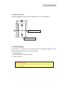
For pcs 1900 mhz system 7 5) installation on the wall the bracket provided can be used to install repeater on the wall as a below figure. 4. Trouble shooting if the repeater is not normal status as followings, please remove power supply off to avoid additional damage and contact service center for r...
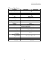
For pcs 1900 mhz system 8 5. Technical specification parameters forward path reverse path frequency range 1930~1990 mhz 1850 ~ 1910 mhz channel bandwidth 60 mhz output level (max) +7 dbm / 11fa +10 dbm / 1fa input level (max) -120 ~ -43 dbm -120 ~ -40 dbm gain 50 db ± 2 db tx/rx isolation ≥ 65 db no...
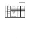
For pcs 1900 mhz system 9 6. Package contains no. Item descriptions q/ty remarks 1 repeater speed home repeater 1 patch antenna for outdoor 1 donor antenna dipole antenna for indoor 1 service antenna assistant device 1 2 antenna screws 4 3 power supply ac_dc adapter 1 assistants 1 screws 2 4 fixing ...


