- DL manuals
- Kawasaki
- Offroad Vehicle
- BRUTE FORCE 750 2008
- Service Manual
Kawasaki BRUTE FORCE 750 2008 Service Manual
Summary of BRUTE FORCE 750 2008
Page 1
Brute force 750 4×4i kvf750 4×4 all terrain vehicle service manual.
Page 3: Quick Reference Guide
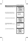
This quick reference guide will assist you in locating a desired topic or pro- cedure. •bend the pages back to match the black tab of the desired chapter num- ber with the black tab on the edge at each table of contents page. •refer to the sectional table of contents for the exact pages to locate th...
Page 5: Brute Force 750 4×4I
Brute force 750 4×4i kvf750 4×4 all terrain vehicle service manual all rights reserved. No parts of this publication may be reproduced, stored in a retrieval system, or transmitted in any form or by any means, electronic mechanical photocopying, recording or otherwise, without the prior written perm...
Page 6
List of abbreviations a ampere(s) lb pounds(s) abdc after bottom dead center m meter(s) ac alternating current min minute(s) atdc after top dead center n newton(s) bbdc before bottom dead center pa pascal(s) bdc bottom dead center ps horsepower btdc before top dead center psi pound(s) per square inc...
Page 7
Emission control information to protect the environment in which we all live, kawasaki has incorporated crankcase emission (1) and exhaust emission (2) control systems in compliance with applicable regulations of the united states environmental protection agency and california air resources board. A...
Page 8
We recommend that all dealers observe these provisions of federal law, the violation of which is punishable by civil penalties not exceeding $10,000 per violation..
Page 9
Please do not tamper with noise control system (us model only) tampering with emission control system prohibited: federal regulations and california state law prohibit the following acts or the causing thereof: (1) the removal or rendering inoperative by any person other than for purposes of mainten...
Page 10: Foreword
Foreword this manual is designed primarily for use by trained mechanics in a properly equipped shop. However, it contains enough detail and basic in- formation to make it useful to the owner who de- sires to perform his own basic maintenance and repair work. A basic knowledge of mechanics, the prope...
Page 11: General Information
General information 1-1 1 general information table of contents before servicing ..................................................................................................................... 1-2 model identification................................................................................
Page 12
1-2 general information before servicing before starting to perform an inspection service or carry out a disassembly and reassembly oper- ation on a vehicle, read the precautions given below. To facilitate actual operations, notes, illustra- tions, photographs, cautions, and detailed descriptions ha...
Page 13
General information 1-3 before servicing arrangement and cleaning of removed parts disassembled parts are easy to confuse. Arrange the parts according to the order the parts were disassembled and clean the parts in order prior to assembly. Storage of removed parts after all the parts including subas...
Page 14
1-4 general information before servicing tightening sequence generally, when installing a part with several bolts, nuts, or screws, start them all in their holes and tighten them to a snug fit. Then tighten them according to the specified se- quence to prevent case warpage or deformation which can l...
Page 15
General information 1-5 before servicing press for items such as bearings or oil seals that must be pressed into place, apply small amount of oil to the con- tact area. Be sure to maintain proper alignment and use smooth movements when installing. Ball bearing and needle bearing do not remove presse...
Page 16
1-6 general information before servicing lubrication it is important to lubricate rotating or sliding parts during assembly to minimize wear during initial operation. Lubri- cation points are called out throughout this manual, apply the specific oil or grease as specified. Direction of engine rotati...
Page 17
General information 1-7 model identification kvf750d8f left side view kvf750d8f right side view the kvf750e is a camouflage-surface-treated model and identical to the kvf750d, the base model, in every other aspect: controls, features, and specifications. The kvf750f is identical to the kvf750d in ev...
Page 18
1-8 general information model identification frame number [a] frame number [b] left front axle engine number [a] engine number [b] torque converter cover.
Page 19
General information 1-9 general specifications items kvf750d8f, e8f, f8f dimensions overall length 2 195 mm (86.42 in.) overall width 1 166 mm (45.90 in.) overall height 1 233 mm (48.54 in.) wheelbase 1 284 mm (50.55 in.) ground clearance: 247 mm (9.72 in.) seat height 903 mm (35.6 in.) dry mass 274...
Page 20
1-10 general information general specifications items kvf750d8f, e8f, f8f engine oil: type api sf or sg api sh, sj or sl with jaso ma viscosity sae 10w-40 capacity 2.6 l (2.7 us qt) drive train primary reduction system: type belt converter reduction ratio 3.122 ∼ 0.635 transmission: type 2-speed and...
Page 21
General information 1-11 general specifications items kvf750d8f, e8f, f8f rim size: front 12 × 6.0 rear 12 × 7.5 front tire: type tubeless size at25 × 8-12 rear tire: type tubeless size at25 × 10-2 suspension: front: type double wishbone wheel travel 171 mm (6.73 in.) rear: type double wishbone whee...
Page 22
1-12 general information unit conversion table prefixes for units: prefix symbol power mega m × 1 000 000 kilo k × 1 000 centi c × 0.01 milli m × 0.001 micro µ × 0.000001 units of mass: kg × 2.205 = lb g × 0.03527 = oz units of volume: l × 0.2642 = gal (us) l × 0.2200 = gal (imp) l × 1.057 = qt (us)...
Page 23: Periodic Maintenance
Periodic maintenance 2-1 2 periodic maintenance table of contents periodic maintenance chart ................................................................................................... 2-3 torque and locking agent..................................................................................
Page 24
2-2 periodic maintenance rear brake lever and pedal free play adjustment ......................................................... 2-35 steering ............................................................................................................................... 2-35 steering inspection .....
Page 25
Periodic maintenance 2-3 periodic maintenance chart the scheduled maintenance must be done in accordance with this chart to keep the vehicle in good running condition. The initial maintenance is vitally important and must not be neglected. Frequency first service regular service operation after 10 h...
Page 26
2-4 periodic maintenance periodic maintenance chart frequency first service regular service operation after 10 hrs. Or 100 km (60 mi.) of use every 10 days or 200 km (120 mi.) of use every 30 days or 600 km (360 mi.) of use every 90 days, 1 700 km (1 100 mi.) of use or when belt indicator light turn...
Page 27
Periodic maintenance 2-5 torque and locking agent the following tables list the tightening torque for the major fasteners, and the parts requiring use of a non-permanent locking agent or liquid gasket. Letters used in the “remarks” column mean: l: apply a non-permanent locking agent. Lb: apply a non...
Page 28
2-6 periodic maintenance torque and locking agent torque fastener n·m kgf·m ft·lb remarks rocker shaft bolts 22 2.2 16 valve adjusting screw locknuts 12 1.2 106 in·lb camshaft chain tensioner mounting bolts 8.8 0.90 78 in·lb camshaft chain tensioner cap bolts 22 2.2 16 position plate bolts 8.8 0.90 ...
Page 29
Periodic maintenance 2-7 torque and locking agent torque fastener n·m kgf·m ft·lb remarks crankcase bolts (m8) 75 mm (2.95 in.) 20 2.0 15 s crankcase bolts (m8) 110 mm (4.33 in.) 20 2.0 15 s crankcase bolt (m8) 110 mm (4.33 in.) 20 2.0 15 s, l crankcase bolts (m6) 40 mm (1.57 in.) 9.8 1.0 87 in·lb c...
Page 30
2-8 periodic maintenance torque and locking agent torque fastener n·m kgf·m ft·lb remarks front final gear case center cover bolts (m6) 9.8 1.0 87 in·lb l front final gear case center cover bolts (m8) 24 2.4 17 l front final gear case oil filler cap 29 3.0 22 pinion gear bearing holder nut 127 13 94...
Page 31
Periodic maintenance 2-9 torque and locking agent torque fastener n·m kgf·m ft·lb remarks steering knuckle joint nuts 29 3.0 21 rear shock absorber mounting nuts 34 3.5 25 stabilizer holder bolts 22 2.2 16 stabilizer joint nuts 46 4.7 34 rear suspension arm pivot nuts 46 4.7 34 rear knuckle mounting...
Page 32
2-10 periodic maintenance torque and locking agent torque fastener n·m kgf·m ft·lb remarks forward/reverse detecting sensor mounting bolt 15 1.5 11 speed sensor mounting bolt 8.8 0.90 78 in·lb neutral position switch 15 1.5 11 reverse position switch 15 1.5 11 ignition coil mounting bolts 5.9 0.60 5...
Page 33
Periodic maintenance 2-11 specifications item standard service limit fuel system throttle lever free play 2 ∼ 3 mm (0.08 ∼ 0.12 in.) – – – idle speed 1 100 ±50 r/min (rpm) – – – air cleaner element oil high-quality foam air filter oil – – – cooling system coolant: type (recommended) permanent type a...
Page 34
2-12 periodic maintenance specifications item standard service limit final drive front final gear case: gear case oil: type api sf or sg – – – api sh, sj or sl with jaso ma – – – viscosity sae 10w-40 – – – oil level filler opening bottom – – – capacity 0.40 l (0.42 us qt) – – – rear final gear case:...
Page 35
Periodic maintenance 2-13 special tools oil filter wrench: 57001-1249 filler cap driver: 57001-1454 pulley holder attachment: 57001-1472 flywheel & pulley holder: 57001-1605 belt measuring gauge: 57001-1646.
Page 36
2-14 periodic maintenance periodic maintenance procedures fuel system throttle lever free play inspection • check that the throttle lever [a] moves smoothly from full open to close, and the throttle closes quickly and com- pletely in all steering positions by the return spring. If the throttle lever...
Page 37
Periodic maintenance 2-15 periodic maintenance procedures idle speed inspection • start the engine and warm it up thoroughly. • with the engine idling, turn the handlebar to both sides to check for any changes in the idle speed. If handlebar movement changes the idle speed, the throt- tle cable may ...
Page 38
2-16 periodic maintenance periodic maintenance procedures air cleaner element cleaning and inspection note ○ in dusty areas, the element should be cleaned more frequently than the recommended interval. ○ after riding through rain or muddy terrains, the element should be cleaned immediately. ○ also, ...
Page 39
Periodic maintenance 2-17 periodic maintenance procedures fuel hose inspection (fuel leak, damage, installation condition) ○ the fuel hose is designed to be used throughout the vehi- cle’s life without any maintenance. However, if the vehicle is not properly handled, the high pressure inside the fue...
Page 40
2-18 periodic maintenance periodic maintenance procedures • twist the screwdriver to disconnect the joint lock [a]. • pull the fuel hose joint [b] out of the delivery pipe. Warning be prepared for fuel spillage; any spilled fuel must be completely wiped up immediately. When the fuel hose is disconne...
Page 41
Periodic maintenance 2-19 periodic maintenance procedures • remove: front guard cover (see front guard removal in the frame chapter) front fender (see front fender removal in the frame chapter) headlight cover (see headlight cover removal in the frame chapter) radiator screen mounting screws [a] rad...
Page 42
2-20 periodic maintenance periodic maintenance procedures • remove: reserve tank screws [a] reserve tank [b] with hose • remove the reserve tank cap [c], and pour the coolant into a container. • place a container under the drain bolt [a] at the bottom of the water pump cover [b], then remove the dra...
Page 43
Periodic maintenance 2-21 periodic maintenance procedures • tighten: torque - coolant drain bolt: 8.8 n·m (0.90 kgf·m, 78 in·lb) • support the vehicle on a stand or the jack so that the front wheels are off the ground. This makes air bleeding easier. • fill the radiator up to the radiator filler nec...
Page 44
2-22 periodic maintenance periodic maintenance procedures engine top end valve clearance inspection note ○ check the valve clearance only when the engine is cold (at room temperature). • remove: front fender (see front fender removal in the frame chapter) battery case valve adjusting cap bolts [a] v...
Page 45
Periodic maintenance 2-23 periodic maintenance procedures • measure the clearance for all four valves, one at a time between the end of the valve stem and the adjusting screw [a] with the thickness gauge [b]. Valve clearance (when cold) exhaust 0.20 ∼ 0.25 mm (0.0079 ∼ 0.0098 in.) inlet 0.10 ∼ 0.15 ...
Page 46
2-24 periodic maintenance periodic maintenance procedures • remove the drain plug [a] on the muffler. • in an open area away from combustible materials, start the engine with the transmission in neutral. • raise and lower engine speed while tapping on the muf- fler with a rubber mallet until carbon ...
Page 47
Periodic maintenance 2-25 periodic maintenance procedures • check the belt [a] for abnormal wear [b]. ○ measure the width [c] of the belt at abnormal wear point. If any measurements exceed 0.5 mm (0.02 in.), replace the belt. ○ when using the belt of large abnormal wear, the drive belt failure detec...
Page 48
2-26 periodic maintenance periodic maintenance procedures converter drive belt deflection adjustment • disassemble the driven pulley (see driven pulley disas- sembly in the converter system chapter). If the belt deflection is more than 27 mm (1.06 in.), remove the spacers to decrease it. ○ the rule-...
Page 49
Periodic maintenance 2-27 periodic maintenance procedures actuator lever (engine brake control lever) assembly inspection • measure the width [a] of the plastic guide shoe [b] of the actuator lever assembly. If the guide contact area width is greater than the service limit, replace the actuator leve...
Page 50
2-28 periodic maintenance periodic maintenance procedures • replace the filter with a new one. • when installing the oil filter, be careful of the following. ○ apply oil to the gasket [a] before installation. ○ tighten the filter with the oil filter wrench. Special tool - oil filter wrench: 57001-12...
Page 51
Periodic maintenance 2-29 periodic maintenance procedures variable differential control lever play adjustment • remove: handlebar cover screws [a] • remove: handlebar cover screws [a] handlebar cover front [b] • loosen the locknut [a] of the differential control cable. • turn the adjuster [b] until ...
Page 52
2-30 periodic maintenance periodic maintenance procedures • fill the gear case up to the bottom of filler opening with the oil specified below. Front final gear case oil type: api sf or sg api sh, sj or sl with jaso ma viscosity: sae 10w-40 capacity: 0.40 l (0.42 us qt) note ○ depending on the atmos...
Page 53
Periodic maintenance 2-31 periodic maintenance procedures • be sure the o-ring [a] is in place, and tighten the filler cap [b]. ○ apply grease to the o-ring. Torque - rear final gear case oil filler cap: 29 n·m (3.0 kgf·m, 22 ft·lb) universal joint lubrication • remove: rear propeller shaft (see rea...
Page 54
2-32 periodic maintenance periodic maintenance procedures front brake hose replacement • pump the brake fluid out of the line as explained in the brake fluid change. • remove the banjo bolts at both ends of the brake hose, and pull the hose off the vehicle. • immediately wipe up any brake fluid that...
Page 55
Periodic maintenance 2-33 periodic maintenance procedures front brake fluid change • remove the reservoir cap and the rubber cap on the bleed valve. • attach a clear plastic hose to the bleed valve on the caliper, and run the other end of the hose into a con- tainer. • fill the reservoir with new br...
Page 56
2-34 periodic maintenance periodic maintenance procedures front brake caliper fluid seal replacement the fluid seals [a] around the piston maintain the proper pad/disc clearance. If the seals are not satisfactory, pad wear will increase, and constant pad drag on the disc will raise brake and brake f...
Page 57
Periodic maintenance 2-35 periodic maintenance procedures rear brake lever and pedal free play adjustment note ○ since the rear brake lever and pedal free play adjust- ments affect each other, make them at the same time. Rear brake lever • loosen the knurled locknut [a] and turn the adjuster [b] at ...
Page 58
2-36 periodic maintenance periodic maintenance procedures • check the steering action again. If steering stem bearing lubrication does not remedy the problem, inspect the steering stem for straightness, steer- ing stem clamps, and tie-rod bearings. If you feel looseness, or if the steering rattles a...
Page 59
Periodic maintenance 2-37 periodic maintenance procedures converter drive belt failure detection system inspection • remove: seat (see seat removal in the frame chapter) • check the drive belt failure detection system according to following chart in the next page..
Page 60
2-38 periodic maintenance periodic maintenance procedures.
Page 61
Periodic maintenance 2-39 periodic maintenance procedures joint boots inspection front axle/steering knuckle joint boots inspection • visually inspect the front axle joint boots [a]. If the joint boot is torn, worn, deteriorated, or leaks grease, replace the joint boot or front axle assembly (see fr...
Page 62
2-40 periodic maintenance periodic maintenance procedures general lubrication lubrication • before lubricating each part, clean off any rusty spots with rust remover and wipe off any grease, oil, dirt, or grime. • lubricate the points listed below with indicated lubricant. Note ○ whenever the vehicl...
Page 63
Periodic maintenance 2-41 periodic maintenance procedures slide points: lubricate with grease. Brake lever brake pedal pivot shaft throttle lever shaft bolts and nuts tightening tightness inspection • check the tightness of the bolts and nuts listed here in accordance with the periodic maintenance c...
Page 65: Fuel System (Dfi)
Fuel system (dfi) 3-1 3 fuel system (dfi) table of contents exploded view........................................................................................................................ 3-4 dfi system...............................................................................................
Page 66
3-2 fuel system (dfi) fuel pump relay removal ............................................................................................... 3-63 fuel pump relay inspection ............................................................................................. 3-63 ignition coils (#1, #2: ser...
Page 67
Fuel system (dfi) 3-3 fuel tank ................................................................................................................................ 3-95 fuel tank removal ........................................................................................................... 3-95 fue...
Page 68
3-4 fuel system (dfi) exploded view.
Page 69
Fuel system (dfi) 3-5 exploded view torque no. Fastener n·m kgf·m ft·lb remarks 1 air cleaner housing bolts 8.8 0.90 78 in·lb 2 isc valve mounting bolts 8.8 0.90 78 in·lb 3 water temperature sensor 12 1.2 106 in·lb 4 air cleaner element holder screw 3.5 0.36 31 in·lb 5 air cleaner element holder tap...
Page 70
3-6 fuel system (dfi) exploded view.
Page 71
Fuel system (dfi) 3-7 exploded view torque no. Fastener n·m kgf·m ft·lb remarks 1 fuel pump bolts 4.0 0.41 35 in·lb 2 fuel tank mounting bolts 9.8 1.0 87 in·lb 3 throttle lever limiter screw 3.6 0.37 32 in·lb 4 throttle lever limiter nut 3.6 0.37 32 in·lb 5 throttle case assembly screws 3.6 0.37 32 ...
Page 72
3-8 fuel system (dfi) dfi system dfi system.
Page 73
Fuel system (dfi) 3-9 dfi system 1. Battery 12 v 12 ah 2. Ecu (electronic control unit) 3. Inlet air pressure sensor 4. Throttle sensor 5. Injectors 6. Crankshaft sensor 7. Isc valve 8. Fuel pump 9. Speed sensor 10. Water temperature sensor 11. Vehicle-down sensor 12. Inlet air temperature sensor 13...
Page 74
3-10 fuel system (dfi) dfi system dfi system wiring diagram.
Page 75
Fuel system (dfi) 3-11 dfi system part name 1. Throttle sensor 2. Fuel injector #1 3. Fuel injector #2 4. Ignition switch 5. Speed sensor 6. Fuse box 7. Fuel pump fuse 10 a 8. Main fuse 30 a 9. Fuel pump 10. Ecu (electronic control unit) 11. Vehicle-down sensor 12. Fuel pump relay 13. Kawasaki diagn...
Page 76
3-12 fuel system (dfi) dfi system terminal names 1. Inlet air pressure sensor signal 2. Inlet air temperature sensor signal 3. Power supply to sensors 4. Reverse switch signal 5. Reverse power assist switch signal 6. Crankshaft sensor (–) signal 7. Battery monitor 8. Power supply to ecu (from batter...
Page 77
Fuel system (dfi) 3-13 dfi parts location fi indicator light (lcd) [a] water temperature sensor [a] spark plug (front) [b] ignition coil (front) [c] crankshaft sensor [a] isc valve [a] spark plug (rear) [b] ignition coil (rear) [c] throttle sensor [a] inlet air pressure sensor [b] fuel injectors [c].
Page 78
3-14 fuel system (dfi) dfi parts location inlet air temperature sensor [a] speed sensor [a] ecu (electronic control unit) [a] battery 12v 12ah [b] fuel pump [c] vehicle-down sensor [a] fuel pump relay [b] kawasaki diagnostic system connector [c].
Page 79
Fuel system (dfi) 3-15 specifications item standard digital fuel injection system idle speed 1 100 ±50 r/min (rpm) throttle body assy: type two barrel type bore 38 mm (1.50 in.) ecu (electronic control unit): make mitsubishi electric type digital memory type, with built in ic igniter, sealed with re...
Page 80
3-16 fuel system (dfi) specifications item standard speed sensor: input voltage battery voltage at ignition switch on output voltage less than cd 0.8 vor over than dc 4.8 v at ignition switch on and 0 km/h throttle lever and cable throttle lever free play 2 ∼ 3 mm (0.08 ∼ 0.12 in.) air cleaner air c...
Page 81
Fuel system (dfi) 3-17 special tools and sealant vacuum gauge adapter: 57001-401 oil pressure gauge, 5 kgf/cm²: 57001-125 pilot screw adjuster, a: 57001-1239 fork oil level gauge: 57001-1290 vacuum gauge: 57001-1369 hand tester: 57001-1394 needle adapter set: 57001-1457 throttle sensor setting adapt...
Page 82
3-18 fuel system (dfi) special tools and sealant fuel pressure gauge adapter: 57001-1593 fuel hose: 57001-1607 speed sensor measuring adapter: 57001-1667 fuel hose l = 550: 57001-1707 kawasaki bond (silicone sealant): 56019-120
Page 83
Fuel system (dfi) 3-19 dfi servicing precautions dfi servicing precautions there are a number of important precautions that should be followed servicing the dfi system. ○ this dfi system is designed to be used with a 12 v sealed battery as its power source. Do not use any other battery except for a ...
Page 84
3-20 fuel system (dfi) dfi servicing precautions ○ to maintain the correct fuel/air mixture (f/a), there must be no inlet air leaks in the dfi system. Be sure to install the oil filler plug [a] after filling the engine oil. Clutch cover [b].
Page 85
Fuel system (dfi) 3-21 troubleshooting the dfi system outline when an abnormality in the dfi system occurs, the fi indicator light (lcd) goes on to alert the rider on the meter panel. In addition, the condition of the problem is stored in the memory of the ecu (electronic control unit). With the eng...
Page 86
3-22 fuel system (dfi) troubleshooting the dfi system ○ the dfi part connectors [a] have seals [b], including the ecu. • join the connector and insert the needle adapters [c] inside the seals [b] from behind the connector until the adapter reaches the terminal. Special tool - needle adapter set: 570...
Page 87
Fuel system (dfi) 3-23 troubleshooting the dfi system • pull each connector [a] apart and inspect it for corrosion, dirt, and damage. If the connector is corroded or dirty, clean it carefully. If it is damaged, replace it. Connect the connectors securely. • check the wiring for continuity. ○ use the...
Page 88
3-24 fuel system (dfi) troubleshooting the dfi system ○ there are two ways to inspect the dfi system. One is voltage check method and the other is resistance check method. (voltage check method) ○ this method is conducted by measuring the input voltage [b] to a sensor [a] first, and then the output ...
Page 89
Fuel system (dfi) 3-25 troubleshooting the dfi system dfi diagnosis flow chart inquiries to rider ○ each rider reacts to problems in different ways, so it is important to confirm what kind of symptoms the rider has encountered. ○ try to find out exactly what problem occurred under exactly what condi...
Page 90
3-26 fuel system (dfi) troubleshooting the dfi system sample diagnosis sheet rider name: registration no. (license plate no.): year of initial registration: model: engine no.: frame no.: date problem occurred: mileage: environment when problem occurred. Weather □ fine, □ cloudy, □ rain, □ snow, □ al...
Page 91
Fuel system (dfi) 3-27 troubleshooting the dfi system □ other □ spark plug loose (tighten it) □ spark plug dirty, broken, or gap maladjusted (remedy it) □ spark plug incorrect (replace it) □ knocking (fuel poor quality or incorrect) □ brake dragging □ clutch slipping □ engine overheating □ engine oi...
Page 92
3-28 fuel system (dfi) dfi system troubleshooting guide note ○ this is not an exhaustive list, giving every possible cause for each problem listed. It is meant simply as a rough guide to assist the troubleshooting for some of the more common difficulties. ○ the ecu may be involved in the dfi electri...
Page 93
Fuel system (dfi) 3-29 dfi system troubleshooting guide symptoms or possible causes actions (chapter) brake lever or pedal not pulled in and gear not in neutral pull the brake lever or pedal in. Vehicle-down sensor coming off reinstall (see chapter 3). Vehicle-down sensor trouble inspect (see chapte...
Page 94
3-30 fuel system (dfi) dfi system troubleshooting guide symptoms or possible causes actions (chapter) valve spring broken or weak inspect and replace (see chapter 5). Valve not seating properly (valve bent, worn or carbon accumulating on seating surface) inspect and repair or replace (see chapter 5)...
Page 95
Fuel system (dfi) 3-31 dfi system troubleshooting guide symptoms or possible causes actions (chapter) fuel injector trouble inspect (see chapter 3). Throttle sensor trouble inspect (see chapter 3). Fuel pressure too low or too high inspect (see chapter 3). Inlet air pressure sensor trouble inspect (...
Page 96
3-32 fuel system (dfi) dfi system troubleshooting guide symptoms or possible causes actions (chapter) too low fuel pressure inspect (see chapter 3). Water or foreign matter in fuel change fuel. Inspect and clean fuel system (see chapter 3). Clogged fuel filter or pump screen inspect and replace fuel...
Page 97
Fuel system (dfi) 3-33 dfi system troubleshooting guide symptoms or possible causes actions (chapter) engine overheating (see overheating of troubleshooting guide, see chapter 17) other: engine oil viscosity too high change (see chapter 2). Brake dragging inspect caliper fluid seal damage or cloggin...
Page 98
3-34 fuel system (dfi) dfi system troubleshooting guide symptoms or possible causes actions (chapter) piston ring bad (worn, weak, broken or sticking) inspect and replace (see chapter 5). Piston ring/groove clearance excessive inspect and replace (see chapter 5). Cylinder head gasket damaged replace...
Page 99
Fuel system (dfi) 3-35 self-diagnosis self-diagnosis outline the self-diagnosis system has two modes and can be switched to another mode by grounding the self-diagnosis terminal. User mode the ecu notifies the rider of troubles in dfi system and ignition system by flashing the fi indicator when dfi ...
Page 100
3-36 fuel system (dfi) self-diagnosis • connect the hand tester [a] as shown. • set the tester to 5 ma range. Special tool - hand tester: 57001-1394 connections: adapter hand tester meter side ← red → (+) main harness side ← black → (–) • ground the self-diagnosis terminal to the battery (–) ter- mi...
Page 101
Fuel system (dfi) 3-37 self-diagnosis.
Page 102
3-38 fuel system (dfi) self-diagnosis how to read service codes ○ service codes are shown by a series of long and short flicks of the tester as shown below. ○ read 10th digit and unit digit as the tester flicks. ○ when there are a number of problems, all the service codes can be stored and the displ...
Page 103
Fuel system (dfi) 3-39 self-diagnosis service code table service code flicks of tester problems 11 throttle sensor malfunction, wiring open or short 12 inlet air pressure sensor malfunction, wiring open or short 13 inlet air temperature sensor malfunction, wiring open or short 14 water temperature s...
Page 104
3-40 fuel system (dfi) self-diagnosis backups ○ the ecu takes the following measures to prevent engine damage when the dfi or the ignition system parts have troubles. Service codes parts output signal usable range or criteria backups by ecu 11 throttle sensor throttle sensor output voltage 0.2 ∼ 4.8...
Page 105
Fuel system (dfi) 3-41 self-diagnosis heavy, the ecu determines the injection quantity by calculating from the throttle opening (throttle sensor output voltage) and the engine speed. This method is called α - n method (high-speed mode)..
Page 106
3-42 fuel system (dfi) throttle sensor (service code 11) throttle sensor removal/adjustment caution do not remove or adjust the throttle sensor [a] since it has been adjusted and set with precision at the factory. Never drop the throttle body assy, especially on a hard surface. Such a shock to the s...
Page 107
Fuel system (dfi) 3-43 throttle sensor (service code 11) if the input voltage is less than the standard, remove the ecu and check the wiring between these connectors. ○ disconnect the ecu and sensor connectors. Wiring connection ecu connector [a] ←→ throttle sensor connector [b] br/w lead (ecu termi...
Page 108
3-44 fuel system (dfi) throttle sensor (service code 11) if the output voltage is normal, check the wiring for conti- nuity. ○ disconnect the ecu and sensor connectors. Wiring connection ecu connector [a] ←→ throttle sensor connector [b] y/w lead (ecu terminal 15) br/bk lead (ecu terminal 10) if the...
Page 109
Fuel system (dfi) 3-45 throttle sensor (service code 11) throttle sensor circuit 1. Ecu (electronic control unit) 2. Throttle sensor.
Page 110
3-46 fuel system (dfi) inlet air pressure sensor (service code 12) caution never drop the sensor, especially on a hard surface. Such a shock to the part can damage it. Inlet air pressure sensor removal • remove: air cleaner (see air cleaner housing removal) screw [a] • disconnect the inlet air press...
Page 111
Fuel system (dfi) 3-47 inlet air pressure sensor (service code 12) inlet air pressure sensor output voltage inspection note ○ the output voltage changes according to the local at- mospheric pressure. • measure the output voltage at the ecu in the same way as input voltage inspection. Note the follow...
Page 112
3-48 fuel system (dfi) inlet air pressure sensor (service code 12) suppose: pg: vacuum pressure (gauge) to sensor pl: local atmospheric pressure (absolute) measured by a barometer pv: vacuum pressure (absolute) to sensor vv: sensor output voltage (v) then pv = pl – pg for example, suppose the follow...
Page 113
Fuel system (dfi) 3-49 inlet air pressure sensor (service code 12) id: idling ps: standard atmospheric pressure (absolute) pv: throttle vacuum pressure (absolute) st: standard of sensor output voltage (v) to: throttle full open ur: usable range of sensor output voltage (v) vv: inlet air pressure sen...
Page 114
3-50 fuel system (dfi) inlet air pressure sensor (service code 12) inlet air pressure sensor circuit 1. Ecu (electronic control unit) 2. Inlet air pressure sensor.
Page 115
Fuel system (dfi) 3-51 inlet air temperature sensor (service code 13) inlet air temperature sensor removal/installation caution never drop the sensor, especially on a hard surface. Such a shock to the sensor can damage it. • remove the air cleaner (see air cleaner housing re- moval). • remove the sc...
Page 116
3-52 fuel system (dfi) inlet air temperature sensor (service code 13) inlet air temperature sensor resistance inspection • remove the inlet air temperature sensor (see inlet air temperature sensor removal/installation). • suspend the sensor [a] in a container of machine oil so that the heat-sensitiv...
Page 117
Fuel system (dfi) 3-53 water temperature sensor (service code 14) water temperature sensor removal/installation caution never drop the sensor, especially on a hard surface. Such a shock to the sensor can damage it. • drain the coolant (see coolant change in the periodic maintenance chapter). • remov...
Page 118
3-54 fuel system (dfi) water temperature sensor (service code 14) water temperature sensor output voltage inspection note ○ be sure the battery is fully charged. ○ the output voltage changes according to the coolant temperature in the engine. • remove the ecu (see ecu removal). ○ do not disconnect t...
Page 119
Fuel system (dfi) 3-55 water temperature sensor (service code 14) water temperature sensor circuit 1. Ecu (electronic control unit) 2. Water temperature sensor.
Page 120
3-56 fuel system (dfi) crankshaft sensor (service code 21) start the engine and switch the diagnosis mode to dealer 1 mode to know all the problem that the dfi system has at the time of self-diagnosis. If the engine cannot be started, the self-diagnosis system does not detect dynamic condi- tion of ...
Page 121
Fuel system (dfi) 3-57 speed sensor (service code 24) speed sensor removal • refer to the speed sensor removal in the electrical sys- tem chapter. Speed sensor installation • refer to the speed sensor installation in the electrical system chapter. Speed sensor inspection • refer to the speed sensor ...
Page 122
3-58 fuel system (dfi) speed sensor (service code 24) output voltage inspection • before this inspection, inspect the input voltage (see input voltage inspection in the speed sensor section). Note ○ be sure the battery is fully charged. • turn the ignition switch off. • using the jack, raise the rea...
Page 123
Fuel system (dfi) 3-59 speed sensor (service code 24) speed sensor circuit 1. Ecu (electronic control unit) 2. Speed sensor 3. Engine ground 4. Multifunction meter.
Page 124
3-60 fuel system (dfi) vehicle-down sensor (service code 31) vehicle-down sensor removal caution never drop the vehicle-down sensor, especially on a hard surface. Such a shock to the sensor can damage it. • remove: seat (see seat removal in the frame chapter) screws [a] vehicle-down sensor [b] conne...
Page 125
Fuel system (dfi) 3-61 vehicle-down sensor (service code 31) • remove the vehicle-down sensor (see vehicle-down sensor removal). ○ do not disconnect the sensor connector. • connect a digital meter [a] to the connector [b] with nee- dle adapter set [c]. Special tool - needle adapter set: 57001-1457 v...
Page 126
3-62 fuel system (dfi) vehicle-down sensor (service code 31) vehicle-down sensor circuit 1. Ecu (electronic control unit) 2. Vehicle-down sensor.
Page 127
Fuel system (dfi) 3-63 fuel pump relay (service code 46) fuel pump relay removal • remove: seat (see seat removal in the frame chapter) fuel pump relay [a] fuel pump relay inspection • refer to the relay inspection in the electrical system chapter..
Page 128
3-64 fuel system (dfi) fuel pump relay (service code 46) fuel pump relay circuit 1. Ecu (electronic control unit) 2. Fuel pump relay 3. Engine ground terminal 4. Battery 12 v 12 ah 5. Engine stop switch 6. Ignition switch 7. Fuel box 8. Fuel pump fuse 10 a 9. Main fuse 30 a 10. Fuel pump.
Page 129
Fuel system (dfi) 3-65 ignition coils (#1, #2: service code 51, 52) ignition coil #1: ignition coil for front cylinder (service code 51) ignition coil #2: ignition coil for rear cylinder (service code 52) ignition coil removal/installation caution never drop the ignition coils, especially on a hard ...
Page 130
3-66 fuel system (dfi) fuel injectors fuel injector removal • remove: air cleaner (see air cleaner housing removal) screw [a] fuel hose (from the delivery pipe) delivery pipe [b] • remove: fuel injectors [a] connectors [b] fuel injector installation • replace the o-rings [a] and seals [b] with a new...
Page 131
Fuel system (dfi) 3-67 fuel injectors • install the delivery pipe [a] on the throttle body assy. • tighten: torque - delivery pipe mounting screws [b]: 5.0 n·m (0.51 kgf·m, 44 in·lb) audible inspection • start the engine. • apply the tip of a screwdriver [a] to the injector [b]. Put the grip end ont...
Page 132
3-68 fuel system (dfi) fuel injectors if the meter doesn’t read as specified, check the following. Main fuse 30 a (see fuse inspection in the electrical system chapter) fuel pump relay (see relay circuit inspection in the electrical system chapter) power source wiring (see wiring diagram below) if t...
Page 133
Fuel system (dfi) 3-69 fuel injectors injector signal test • prepare two test light sets with terminals as shown. Rating of bulb [a]: 12 v × (3 ∼ 3.4) w terminal width [b]: 1.8 mm (0.071 in.) terminal thickness [c]: 0.8 mm (0.031 in.) caution do not use larger terminals than specified above. A large...
Page 134
3-70 fuel system (dfi) fuel injectors injector unit test • use two leads [a] and the same test light set [b] as in “injector signal test”. Rating of bulb [c]: 12 v × (3 ∼ 3.4) w 12 v battery [d] caution be sure to connect the bulb in series. The bulb works as a current limiter to protect the solenoi...
Page 135
Fuel system (dfi) 3-71 fuel injectors fuel injector circuit 1. Fuel injector #1 2. Fuel injector #2 3. Ignition switch 4. Fuse box 5. Fuel pump fuse 10 a 6. Main fuse 30 a 7. Ecu (electronic control unit) 8. Fuel pump relay 9. Engine ground terminal 10. Battery 12 v 12 ah 11. Engine stop switch.
Page 136
3-72 fuel system (dfi) fi indicator light (lcd) inspection flow chart.
Page 137
Fuel system (dfi) 3-73 fi indicator light (lcd) light inspection ○ the fi indicator light (lcd) [a] goes on when the ignition switch is turned on and the fi indicator light (lcd) goes off when the engine oil pressure is high enough (the engine is running). This is to ensure that the fi indicator lig...
Page 138
3-74 fuel system (dfi) ecu caution never drop the ecu, especially on a hard surface. Such a shock to the ecu can damage it. Ecu removal • remove: seat (see seat removal in the frame chapter) ecu [a] • disconnect the ecu connectors [b]. Ecu installation • connect the ecu connectors [a] to the ecu [b]...
Page 139
Fuel system (dfi) 3-75 ecu • check the ecu power source voltage with a digital meter [a]. ○ position the terminal in accordance with terminal numbers of ecu connector [b] in this chapter figure. Battery [c] ecu power source inspection meter connections: between terminal 8 (w) and battery (–) termina...
Page 140
3-76 fuel system (dfi) fuel line fuel pressure inspection note ○ this inspection can determine which trouble the dfi system has, mechanical or electrical trouble. ○ it is preferable to measure the fuel pressure while run- ning the vehicle just when trouble occurred in order to know symptom well. ○ b...
Page 141
Fuel system (dfi) 3-77 fuel line note ○ the gauge needle will fluctuate. Read the pressure at the average of the maximum and minimum indications. If the fuel pressure is much lower than specified, the fuel pressure regulator in the fuel pump have been clogged or stuck. Replace the fuel pump (see fue...
Page 142
3-78 fuel system (dfi) fuel line • open the fuel tank cap [a] to lower the pressure in the tank. • temporarily, install the ecu [a] and actuator controller [b]. • connect the prepared fuel hose [a] to the fuel pump outlet pipe. • secure the fuel hose with a clamp. • run the other side of the fuel ho...
Page 143
Fuel system (dfi) 3-79 fuel pump fuel pump removal caution never drop the fuel pump, especially on a hard sur- face. Such a shock to the pump can damage it. Warning gasoline is extremely flammable and can be explo- sive under certain conditions. Make sure the area is well-ventilated and free from an...
Page 144
3-80 fuel system (dfi) fuel pump • remove: fuel pump bolts [a] plate [b] fuel pump [c] o-ring fuel pump installation • remove dirt or dust from the fuel pump [a] by lightly ap- plying compressed air. • install: fuel pump [a] o-ring • install the plate [b] so that fit the projections [c] and hel- low...
Page 145
Fuel system (dfi) 3-81 fuel pump fuel pump operation inspection note ○ be sure the battery is fully charged. ○ just listen to the pump sound in the fuel tank to confirm pump operation. • turn the ignition switch on and make sure that the fuel pump operates (make light sounds) for 3 seconds, and then...
Page 146
3-82 fuel system (dfi) fuel pump pressure regulator removal ○ the pressure regulator [a] is built into the fuel pump [b] and cannot be removed. Pump screen, fuel filter cleaning ○ the pump screen [a] and fuel filter [b] are built into the pump and cannot be cleaned or checked. If the fuel filter is ...
Page 147
Fuel system (dfi) 3-83 fuel pump fuel pump circuit 1. Ecu (electronic control unit) 2. Fuel pump relay 3. Engine ground terminal 4. Battery 12 v 12 ah 5. Engine stop switch 6. Ignition switch 7. Fuse box 8. Fuel pump fuse 10 a 9. Main fuse 30 a 10. Fuel pump.
Page 148
3-84 fuel system (dfi) throttle lever and cable throttle lever free play inspection • refer to the throttle lever free play inspection in the periodic maintenance chapter. Throttle lever free play adjustment • refer to the throttle lever free play adjustment in the periodic maintenance chapter. Thro...
Page 149
Fuel system (dfi) 3-85 throttle lever and cable • install the throttle case so that the projection [a] fit to the hole [b] of the handlebar. • swing the throttle control lever so that the carburetor throt- tle valve is fully open. Turn the throttle limiter screw [a] until it is spaced about 1 mm (0....
Page 150
3-86 fuel system (dfi) throttle body assy idle speed inspection • refer to the idle speed inspection in the periodic main- tenance chapter. Throttle body assy removal warning gasoline is extremely flammable and can be ex- plosive under certain conditions. Turn the ignition switch off. Disconnect the...
Page 151
Fuel system (dfi) 3-87 throttle body assy • turn the throttle pully [a] clockwise to remove the throttle cable tip [b]. • loosen the locknut [c] and adjusting nut [d] fully to re- move the throttle cable from the throttle body assy. • loosen the clamp screws [a] fully. • remove the throttle body ass...
Page 152
3-88 fuel system (dfi) throttle body assy • apply a thin coating of grease to the throttle cable lower end. • fit the throttle cable lower end [a] into the throttle pulley [b]. • tighten the adjusting nut [c] and locknut [d]. • be sure to install the seal [a] on the throttle link case cover. • insta...
Page 153
Fuel system (dfi) 3-89 throttle body assy throttle body assy assembly • install the drain tube [a], if removed • install the inlet air pressure sensor [b] • tighten: torque - inlet air pressure sensor mounting screw [c]: 5.0 n·m (0.51 kgf·m, 44 in·lb) • connect the vacuum hose [d]. Engine vacuum syn...
Page 154
3-90 fuel system (dfi) throttle body assy • remove the bypass screw [a], spring [b], washer [c] and o-ring [d]. ○ check the bypass screw and its hole for carbon deposits. If any carbon accumulates, wipe the carbon off the bypass screw and the hole, using a cotton pad penetrated with a high-flash poi...
Page 155
Fuel system (dfi) 3-91 isc valve isc valve removal • remove: front fender (see front fender removal in the frame chapter) isc valve tube (front) [a] isc valve tube (rear) [b] isc valve tube (primary) [c] connector [d] bolts [e] isc valve [f] isc valve installation • install the isc valve. • tighten:...
Page 156
3-92 fuel system (dfi) air cleaner air cleaner element removal • remove: seat (see seat removal in the frame chapter) clips [a] air cleaner housing cap [b] • remove: element holder screws [a] element holder [b] element [c] • after removing the element, stuff pieces of lint-free, clean cloth into the...
Page 157
Fuel system (dfi) 3-93 air cleaner • remove: screw [a] air intake duct [b] tube [c] isc valve inlet tube [d] • remove: tube [a] air cleaner housing bolts [b] (both side) • loosen the clamp screw [a]. • loosen the clamp screw [a]. • while pulling up the air cleaner housing, remove the breathe hose [a...
Page 158
3-94 fuel system (dfi) air cleaner air cleaner housing installation • install: dust seal [a] air cleaner housing cover [b] [c] inside • be sure to the inlet air temperature sensor [a] is installed. • install: clamp [a] and breather hose inlet air temperature sensor connector [b] • install the air cl...
Page 159
Fuel system (dfi) 3-95 fuel tank fuel tank removal warning gasoline is extremely flammable and can be explo- sive under certain conditions. Make sure the area is well-ventilated and free from any source of flame or sparks; this includes any appliance with a pilot light. Do not smoke. Turn the igniti...
Page 160
3-96 fuel system (dfi) fuel tank • remove the quick rivets [a] to speparate the fuel tank [b] and tank case [c]. Fuel tank installation • note the above warning (see fuel tank removal) • check the insulators [a] on the tank case. If the insulators are damaged or deteriorated, replace them. • check t...
Page 161
Fuel system (dfi) 3-97 fuel tank • install: hose [a] clamps [b] • insert the fuel hose joint [a] straight onto the delivery pipe until the hose joint clicks. • push [b] the joint lock [c] . • push and pull [a] the hose joint [b] back and forth more than two times and make sure it is locked and doesn...
Page 163: Cooling System
Cooling system 4-1 4 cooling system table of contents exploded view........................................................................................................................ 4-2 coolant flow chart.............................................................................................
Page 164
4-2 cooling system exploded view.
Page 165
Cooling system 4-3 exploded view torque no. Fastener n·m kgf·m ft·lb remarks 1 radiator mounting bolts 8.8 0.90 78 in·lb 2 radiator screen mounting bolts 4.0 0.40 35 in·lb 3 radiator fan assembly bolts 4.9 0.50 43 in·lb 4 thermostat housing cover bolts 8.8 0.90 78 in·lb 5 water pump cover bolts 8.8 ...
Page 166
4-4 cooling system coolant flow chart permanent type antifreeze is used as a coolant to protect the cooling system from rust and corrosion. When the engine starts, the water pump (coupled with the oil pump) turns and the coolant circulates. The thermostat is a wax pellet type which opens or closes w...
Page 167
Cooling system 4-5 coolant flow chart 1. Radiator 2. Radiator cap 3. Radiator fan 4. Water temperature switch 5. Thermostat 6. Cylinder 7. Cylinder head 8. Water pump 9. Reserve tank black painted arrow: hot coolant white painted arrow: cold coolant.
Page 168
4-6 cooling system specifications item standard service limit coolant provided when shipping type permanent type of antifreeze (soft water and ethylene glycol plus corrosion and rust inhibitor chemicals for aluminum engines and radiators) – – – color green – – – mixed ratio soft water 50%, coolant 5...
Page 169
Cooling system 4-7 special tools bearing driver set: 57001-1129 bearing remover shaft, 9: 57001-1265 bearing remover head, 10 × 12: 57001-1266.
Page 170
4-8 cooling system coolant coolant deterioration inspection • remove: left footboard (see left footboard removal in the frame chapter) • visually inspect the coolant in the reserve tank [a]. If whitish cotton-like wafts are observed, aluminum parts in the cooling system are corroded. If the coolant ...
Page 171
Cooling system 4-9 coolant pressure testing • remove: front fender (see front fender removal in the frame chapter) • remove the radiator cap, and install a cooling system pressure tester [a] on the radiator filler neck. Note ○ wet the cap sealing surfaces with water or coolant to prevent pressure le...
Page 172
4-10 cooling system water pump water pump cover removal • drain the coolant (see coolant change in the periodic maintenance chapter). • remove: radiator hose [a] water pump cover bolts [b] water pump cover [c] water pump cover installation • install: knock pins [a] new gasket [b] • tighten: torque -...
Page 173
Cooling system 4-11 water pump water pump impeller inspection • visually inspect the impeller [a]. If the surface is corroded or the blades are damaged, re- place the impeller. Water pump leakage inspection • check the drainage catch tank [a] at the bottom of the water pump body for coolant leakage....
Page 174
4-12 cooling system water pump • apply heat-resistance grease on the oil seal lip. • from outside the alternator cover, press and insert the oil seal [a] so that its surface is flush with the step portion of the cover as shown [b]. Special tool - bearing driver set: 57001-1129 • from inside the alte...
Page 175
Cooling system 4-13 radiator radiator removal warning the radiator fan is connected directly to the bat- tery. The radiator fan may start even if the ignition switch is off. Never touch the radiator fan until the radiator fan connector is dis- connected. Touching the fan before the connector is disc...
Page 176
4-14 cooling system radiator • pull the projections [a] out of from the dampers [b], and remove the radiator [c]. Caution do not touch the radiator core. This could damage the radiator fins, resulting in loss of cooling effi- ciency. Radiator installation • insert the projections of the radiator in ...
Page 177
Cooling system 4-15 radiator • remove: radiator fan mounting nut [a] radiator fan [b] radiator fan installation • install: radiator fan radiator fan mounting nut • install: radiator fan assembly • tighten: torque - radiator fan assembly bolts: 4.9 n·m (0.50 kgf·m, 43 in·lb) radiator inspection • che...
Page 178
4-16 cooling system radiator • install the cap [a] on a cooling system pressure tester [b]. Note ○ wet the cap sealing surfaces with water or coolant to prevent pressure leakage. • watching the pressure gauge, slowly pump the pressure tester to build up the pressure. The relief valve opens, indicate...
Page 179
Cooling system 4-17 thermostat thermostat removal • drain the coolant (see coolant change in the periodic maintenance chapter). • remove: front fender (see front fender removal in the frame chapter) water temperature sensor connector [a] • remove: water pipe bolt [a] • remove: thermostat housing cov...
Page 180
4-18 cooling system thermostat thermostat inspection • remove the thermostat, and inspect the thermostat valve [a] at room temperature. If the valve is open, replace the valve with a new one. • to check valve opening temperature, suspend the ther- mostat [a] and an accurate thermometer [b] in a cont...
Page 181
Cooling system 4-19 water temperature sensor water temperature sensor removal/installation caution the water temperature sensor should never be al- lowed to fall on a hard surface. Such a shock to water temperature sensor can damage it. • refer to the water temperature sensor removal/instal- lation ...
Page 183: Engine Top End
Engine top end 5-1 5 engine top end table of contents exploded view................................... 5-2 specifications .................................... 5-8 special tools and sealant ................. 5-10 camshaft chain tensioner ................ 5-12 camshaft chain tensioner removal ...........
Page 184
5-2 engine top end exploded view.
Page 185
Engine top end 5-3 exploded view torque no. Fastener n·m kgf·m ft·lb remarks 1 rocker case bolts 55 mm (2.2 in.) 8.8 0.90 78 in·lb s 2 rocker case bolts 130 mm (5.1 in.) 9.8 1.0 87 in·lb s 3 rocker case bolts 30 mm (1.2 in.) 9.8 1.0 87 in·lb s 4 rocker case bolts 25 mm (1.0 in.) 9.8 1.0 87 in·lb s 5...
Page 186
5-4 engine top end exploded view.
Page 187
Engine top end 5-5 exploded view torque no. Fastener n·m kgf·m ft·lb remarks 1 camshaft chain tensioner mounting bolts 8.8 0.90 78 in·lb 2 camshaft chain tensioner cap bolts 22 2.2 16 3 position plate bolts 8.8 0.90 78 in·lb 4 intermediate shaft chain guide bolts 8.8 0.90 78 in·lb eo 5 intermediate ...
Page 188
5-6 engine top end exploded view.
Page 189
Engine top end 5-7 exploded view torque no. Fastener n·m kgf·m ft·lb remarks 1 exhaust pipe cover bolts 8.8 0.90 78 in·lb 2 muffler clamp bolt 8.8 0.90 78 in·lb 3 muffler cover bolts 8.8 0.90 78 in·lb 4 muffler mounting nuts 19.6 2.0 14 5 muffler mounting locknuts 31.4 3.2 23 6 exhaust pipe holder n...
Page 190
5-8 engine top end specifications item standard service limit rocker case rocker arm inside diameter 12.000 ∼ 12.018 mm (0.4724 ∼ 0.4731 in.) 12.05 mm (0.474 in.) rocker shaft diameter 11.983 ∼ 11.994 mm (0.4718 ∼ 0.4722 in.) 11.96 mm (0.471 in.) camshafts cam height: exhaust 35.363 ∼ 35.477 mm (1.3...
Page 191
Engine top end 5-9 specifications item standard service limit valve/valve guide clearance (wobble method): exhaust 0.09 ∼ 0.17 mm (0.0035 ∼ 0.0067 in.) 0.37 mm (0.0146 in.) inlet 0.03 ∼ 0.11 mm (0.0012 ∼ 0.0043 in.) 0.31 mm (0.0122 in.) valve seat cutting angle 45°, 32°, 60° – – – valve seating surf...
Page 192
5-10 engine top end special tools and sealant outside circlip pliers: 57001-144 compression gauge, 20 kgf/cm²: 57001-221 valve spring compressor assembly: 57001-241 piston pin puller assembly: 57001-910 valve seat cutter, 45° - 27.5: 57001-1114 valve seat cutter, 32° - 28: 57001-1119 valve seat cutt...
Page 193
Engine top end 5-11 special tools and sealant valve spring compressor adapter, 22: 57001-1202 valve guide arbor, 5: 57001-1203 valve guide reamer, 5: 57001-1204 valve seat cutter holder, 5: 57001-1208 piston pin puller adapter, 14: 57001-1211 compression gauge adapter, m10 × 1.0: 57001-1317 filler c...
Page 194
5-12 engine top end camshaft chain tensioner camshaft chain tensioner removal caution this is a non-return type cam chain tensioner. The push rod does not return to its original position once it moves out to take up cam chain slack. Ob- serve all the rules listed below: when removing the tensioner, ...
Page 195
Engine top end 5-13 camshaft chain tensioner camshaft chain tensioner installation • push the stopper [a] to release the ratchet and push the push rod [b] into the tensioner body. • tighten: torque - camshaft chain tensioner mounting bolts: 8.8 n·m (0.90 kgf·m, 78 in·lb) • install: pin [a] and sprin...
Page 196
5-14 engine top end rocker case rocker case removal front rocker case • remove: front fender (see front fender removal in the frame chapter) alternator outer cover bolts [a] alternator outer cover [b] timing inspection plug [c] special tool - filler cap driver: 57001-1454 • remove: valve adjusting c...
Page 197
Engine top end 5-15 rocker case • insert a suitable bar [a] under the front of the engine. • lift [a] the front of the engine to remove the bolt [b] of the front right side on the rocker case. • lift the rocker case to clear of the dowel pins in the cylin- der head and slide the rocker case out of t...
Page 198
5-16 engine top end rocker case • apply silicone sealant to the outer surface of the cap [a] and the cylinder head upper surface [b] as shown. Sealant - kawasaki bond (liquid gasket - gray): 92104 -1063 • tighten the rocker case bolts following the tightening se- quence shown. Torque - rocker case b...
Page 199
Engine top end 5-17 rocker case • using a m8 bolt [a], remove the rocker shaft [b]. • remove: rocker arm [c] washers [d] ○ mark and record the rocker arm location so it can be in- stalled in the original position. ○ the rocker arms come off with the rocker shafts. Rocker arm installation • apply eng...
Page 200
5-18 engine top end rocker case rocker shaft diameter measurement • measure the diameter [a] of the rocker shaft where the rocker arm pivots on it with a micrometer. If the rocker shaft diameter is smaller than the service limit, replace it. Also check the rocker arm inside diameter (see rocker arm ...
Page 201
Engine top end 5-19 camshaft camshaft removal • remove: camshaft chain tensioners (see camshaft chain ten- sioner removal) rocker cases (see rocker case removal) camshafts [a] • support the chain using a suitable tool. Camshaft installation • using a wrench on the alternator bolt, turn the crankshaf...
Page 202
5-20 engine top end camshaft • face the arrow [a] of the front camshaft sprocket upward (right side view). • engage the front camshaft chain with the front camshaft sprocket. • align the marks [b] on the weights with the front cylinder head upper surface. • install: rocker cases (see rocker case ins...
Page 203
Engine top end 5-21 camshaft camshaft bearing wear inspection ○ the journal wear is measured using plastigage (press gauge), which is inserted into the clearance to be mea- sured. The plastigage indicates the clearance by the amount it is compressed and widened when the parts are assembled. • cut st...
Page 204
5-22 engine top end camshaft kacr inspection the kawasaki automatic compression release (kacr) momentarily opens the exhaust valves on the compression stroke at very low speeds. This allows some of the com- pression pressure to escape, making it easy to turn over the engine during starting. Due to t...
Page 205
Engine top end 5-23 camshaft • remove: circlips [a] weights [b] spring [c] note ○ do not remove the shaft [a] and pin [b]. ○ if the parts are removed, they cannot be reinstalled. Kacr installation • install: weights circlips spring [a] ○ hook the spring from the outside with the open side of the hoo...
Page 206
5-24 engine top end camshaft • remove (right side view): torque converter cover (see torque converter cover removal in the converter system chapter) • using a m6 bolt [a], pull out the cover [b]. • remove (left side view): circlip [a] special tool - outside circlip pliers: 57001-144 • remove: interm...
Page 207
Engine top end 5-25 camshaft front camshaft chain • install the circlip [a]. Special tool - outside circlip pliers: 57001-144 • rotate the crankshaft clockwise 270°. • align the key grooves [b] on the crankshaft with the em- bossed line [c] on the crankcase. • move the intermediate shaft [a] to the ...
Page 208
5-26 engine top end camshaft • install the intermediate shaft chain tensioner [a] as fol- lows: • release the stopper [b] and push the push rod [c] into the tensioner body. • insert a wire [d] into the rod hole to hold the rod in place. • install: intermediate shaft chain tensioner [a] • tighten: to...
Page 209
Engine top end 5-27 camshaft • install: rocker cases (see rocker case installation) camshaft chain tensioners (see camshaft chain ten- sioner installation) • check the valve clearances (see valve clearance inspec- tion). Camshaft chain guide wear inspection • visually inspect the rubber on the guide...
Page 210
5-28 engine top end cylinder head cylinder compression measurement note ○ use the battery which is fully charged. • warm up the engine thoroughly, and stop the engine. • remove the spark plug (see spark plug removal in the electrical system chapter). • attach the compression gauge [a] and adapter [b...
Page 211
Engine top end 5-29 cylinder head cylinder head removal • drain the coolant (see coolant change in the periodic maintenance chapter). • remove: throttle body (see throttle body removal in the fuel system (dfi) chapter) exhaust pipe (see muffler and exhaust pipe removal) thermostat (see thermostat re...
Page 212
5-30 engine top end cylinder head • apply molybdenum disulfide oil to the threads and seating surface of the cylinder head bolts and both sides of the washers. • tighten the cylinder head bolts [a] following the tightening sequence as shown. First torque - cylinder head bolts (m10): 25 n·m (2.5 kgf·...
Page 213
Engine top end 5-31 valves valve clearance inspection • refer to the valve clearance inspection in the periodic maintenance chapter. Valve clearance adjustment • refer to the valve clearance adjustment in the periodic maintenance chapter. Valve removal • remove the cylinder head (see cylinder head r...
Page 214
5-32 engine top end valves valve guide installation • lightly oil the valve guide outer surface. • using the valve guide arbor [a], drive the valve guide [b] until its flange touches the cylinder head. Special tool - valve guide arbor, 5: 57001-1203 • ream the valve guide with the valve guide reamer...
Page 215
Engine top end 5-33 valves valve seat inspection • remove the valve (see valve removal). • check the valve seating surface [a] between the valve [b] and valve seat [c]. ○ coat the valve seat with machinist’s dye. ○ push the valve into the guide. ○ rotate the valve against the seat with a lapping too...
Page 216
5-34 engine top end valves seat cutter operation care 1. This valve seat cutter is developed to grind the valve seat for repair. Therefore the cutter must not be used for other purposes than seat repair. 2. Do not drop or shock the valve seat cutter, or the dia- mond particles may fall off. 3. Do no...
Page 217
Engine top end 5-35 valves widened width [a] of engagement by machining with 45° cutter ground volume [b] by 32° cutter 32° [c] correct width [d] ground volume [e] by 60° cutter 60° [f] • measure the outside diameter of the seating surface with vernier calipers. If the outside diameter of the seatin...
Page 218
5-36 engine top end valves if the seat width is too wide, make the 60° [a] grind de- scribed below. If the seat width is within the specified range, lap the valve to the seat as described below. • grind the seat at a 60° angle until the seat width is within the specified range. ○ to make the 60° gri...
Page 219
Engine top end 5-37 valves.
Page 220
5-38 engine top end cylinder and piston cylinder removal • remove: cylinder head (see cylinder head removal) oil pipe [a] chain guide [b] cylinder bolts [c] cylinder [d] cylinder base gasket piston removal • remove the cylinder block (see cylinder removal). • place a piece of clean cloth under the p...
Page 221
Engine top end 5-39 cylinder and piston note ○ the oil ring rails have no “top” or “bottom”. • install the oil ring expander [a] in the bottom piston ring groove so the ends [b] butt together. • install the oil ring steel rails, one above the expander and one below it. ○ spread the rail with your th...
Page 222
5-40 engine top end cylinder and piston • install: cylinder [a] • tighten: torque - cylinder bolts [b]: 9.8 n·m (1.0 kgf·m, 87 in·lb) • install: chain guide [c] • apply oil to the o-ring on the oil pipe [d], and insert the pipe. Cylinder wear inspection • since there is a difference in cylinder wear...
Page 223
Engine top end 5-41 cylinder and piston piston ring, piston ring groove wear inspection • check for uneven groove wear by inspecting the ring seat- ing. The rings should fit perfectly parallel to groove surfaces. If not, replace the piston and all the piston rings. • with the piston rings in their g...
Page 224
5-42 engine top end cylinder and piston piston ring end gap inspection • place the piston ring [a] inside the cylinder, using the pis- ton to locate the ring squarely in place. Set it close to the bottom of the cylinder, where cylinder wear is low. • measure the gap [b] between the ends of the ring ...
Page 225
Engine top end 5-43 exhaust system this vehicle is equipped with a spark arrester approved for off-road use by the united states forest service. It must be properly maintained to ensure its efficiency. In accor- dance with the periodic maintenance chart, clean the spark arrester. Spark arrester clea...
Page 226
5-44 engine top end exhaust system • remove: front exhaust pipe nuts [a] • move the front exhaust pipe rear end [a] under the fuel tank. • move the front exhaust pipe front end [a] as shown. • turn the front exhaust pipe front end to install the front exhaust pipe. Muffler and exhaust pipe installat...
Page 227
Engine top end 5-45 exhaust system • if the muffler cover [a], rear and middle exhaust pipe cov- ers [b] [c] are removed, tighten them. Torque - muffler cover bolts [d]: 8.8 n·m (0.90 kgf·m, 78 in·lb) rear exhaust pipe cover bolts [e]: 8.8 n·m (0.90 kgf·m, 78 in·lb) middle exhaust pipe cover bolts [...
Page 229: Converter System
Converter system 6-1 6 converter system table of contents exploded view........................................................................................................................ 6-2 specifications ............................................................................................
Page 230
6-2 converter system exploded view.
Page 231
Converter system 6-3 exploded view torque no. Fastener n·m kgf·m ft·lb remarks 1 drive pulley bolt 93 9.5 68 r, lh 2 driven pulley nut 93 9.5 68 3 drive pulley cover bolts 13 1.3 115 in·lb 4 ramp weight nuts 6.9 0.70 61 in·lb 5 spider 275 28 203 lh g: apply grease. Lh: left-hand threads r: replaceme...
Page 232
6-4 converter system exploded view.
Page 233
Converter system 6-5 exploded view torque no. Fastener n·m kgf·m ft·lb remarks 1 torque converter cover bolts 8.8 0.90 78 in·lb s 2 engine brake actuator mounting bolts 8.8 0.90 78 in·lb s g: apply grease. M: apply molybdenum disulfide grease. R: replacement part s: follow the specific tightening se...
Page 234
6-6 converter system specifications item standard service limit torque converter actuator lever guide shoe – – – 6 mm (0.24 in.) drive belt belt width 29.7 ∼ 30.3 mm (1.17 ∼ 1.19 in.) 28.0 mm (1.10 in.) belt deflection 22 ∼ 27 mm (0.87 ∼ 1.06 in.) – – – drive pulley shoe side clearance up to 0.20 mm...
Page 235
Converter system 6-7 special tools outside circlip pliers: 57001-144 drive & driven pulley holder: 57001-1412 drive pulley puller bolt: 57001-1429 pulley holder attachment: 57001-1472 drive & driven pulley holder: 57001-1473 drive pulley wrench: 57001-1474 spring holder set: 57001-1483 drive pulley ...
Page 236
6-8 converter system special tools flywheel & pulley holder: 57001-1605.
Page 237
Converter system 6-9 torque converter cover warning excessive imbalance or operating rpm could cause torque converter pulley failure resulting in severe injury or death. The pulleys of the belt drive torque converter are precision balanced components de- signed to operate within certain rpm limits. ...
Page 238
6-10 converter system torque converter cover torque converter cover installation • check the actuator lever assembly installation length (see torque converter cover assembly). • fit the trim seal into the converter cover. ○ set the trim seal juncture in the area [a] when insert the trim seal in the ...
Page 239
Converter system 6-11 torque converter cover actuator lever (engine brake control lever) assembly inspection • refer to the actuator lever (engine brake control lever) assembly inspection in the periodic maintenance chap- ter. Torque converter cover assembly • install: new circlip spring actuator le...
Page 240
6-12 converter system torque converter cover actuator lever assemblies part number paint color [a] length [b] 13236-0046 yellow 0.4 ±0.1 mm (0.016 ±0.004 in.) 13236-0048 none 1.0 ±0.1 mm (0.039 ±0.004 in.) 13236-0047 green 1.6 ±0.1 mm (0.063 ±0.004 in.).
Page 241
Converter system 6-13 drive belt drive belt removal • remove the drive pulley (see drive pulley removal). Note ○ before removing, observe the direction the belt’s printed information [a] (such as manufacturer’s name) is facing so that it may be reinstalled on the pulleys to rotate in the same direct...
Page 242
6-14 converter system drive pulley drive pulley removal • remove: torque converter cover (see torque converter cover removal) right footboard (see right footboard removal in the frame chapter) • remove the three cover bolts [a] and install the drive pul- ley holder [b]. Special tool - drive pulley h...
Page 243
Converter system 6-15 drive pulley • set the pulley onto the pulley holder. • remove: drive pulley cover bolts [a] drive pulley cover [b] • remove: spring [a] spacer • put the drive pulley wrench [a] on the spider [b] and tighten the bolt [c]. Special tool - drive pulley wrench: 57001-1474 • turn th...
Page 244
6-16 converter system drive pulley drive pulley inspection if the sheave surfaces [a] appear damaged, replace the sheaves. If the cover bushing is damaged or worn, replace the drive pulley cover. Cover bushing inside diameter [a] standard: 27.985 ∼ 28.085 mm (1.1018 ∼ 1.1057 in.) service limit: 28.1...
Page 245
Converter system 6-17 drive pulley if the rollers [a] are damaged or worn, replace the spider [b]. If the washers [c] are damaged or worn, replace the spi- der. If the spring is worn or damaged, replace the spring. Spring free length [a] standard: 59.5 mm (2.34 in.) spider shoe side clearance inspec...
Page 246
6-18 converter system drive pulley • turn the movable sheave counterclockwise. • measure the resulting clearance [a] between the shoe [b] and the post [c] on the movable sheave at two positions as shown. [d] arrow mark shoe side clearance standard: up to 0.20 mm (0.008 in.), and there must be kept a...
Page 247
Converter system 6-19 drive pulley • hold the fixed sheave [a] with the drive pulley holder [b] in a vise. Special tool - drive & driven pulley holder: 57001-1473 • clean the threads of the fixed sheave and spider. • install: movable sheave spider [a] and shoes [b] ○ align the arrow [c] on the spide...
Page 248
6-20 converter system drive pulley • install the drive pulley, stepped waster and two washers on the drive pulley bolt as shown. Crankcase side [a] stepped washer [b] two washers [c] bolt head side [d] • remove the three cover bolts [a] and install the drive pul- ley holder [b]. Special tool - drive...
Page 249
Converter system 6-21 drive pulley ○ install the drive pulley measurement tool (legs [a] and plate [b]) on the crankcase [c]. Special tool - drive pulley measurement tool: 57001-1498 ○ measure the length [d] between the plate and collar [e] with vernier calipers [f] or a depth gauge. Measurement len...
Page 250
6-22 converter system driven pulley driven pulley removal • remove: torque converter cover (see torque converter cover removal) drive pulley (see drive pulley removal) drive belt (see drive belt removal) • using the flywheel & pulley holder [a] and attachments [b], remove the driven pulley nut [c] a...
Page 251
Converter system 6-23 driven pulley • confirm the paint mark “0” [a] on the movable sheave [b] in alignment with the point [c] on the fixed sheave [d] for phase fit of the sheaves. • wipe off the molybdenum disulfide grease. • remove the four pins [a] with a thin standard tip screw- driver [b]. • re...
Page 252
6-24 converter system driven pulley if the sheave bushings [a] are damaged or worn, replace the movable sheave. Sheave bushing inside diameter standard: 40.000 ∼ 40.039 mm (1.5748 ∼ 1.5763 in.) service limit: 40.07 mm (1.578 in.) • inspect seals for damage. If seals are damaged, replace the movable ...
Page 253
Converter system 6-25 driven pulley • align the paint mark “0” [a] on the movable sheave [b] with the point [c] on the fixed sheave [d] for phase fit of the sheaves. ○ in that case the opening [a] and hole [b] will be matched easily. • apply grease (wr500-no.2 (kyodo yushi), power lite wr #2 (kyodo ...
Page 254
6-26 converter system driven pulley • hold the drive & driven pulley holder in a vise. Special tool - drive & driven pulley holder: 57001-1473 • screw the guide bar into the holder. Special tool - spring holder set: 57001-1483 • put the driven pulley [a] onto the guide bar. • put the thrust plate [b...
Page 255
Converter system 6-27 driven pulley • install two washers [a] on the shaft as shown. Crankcase side [b] bolt head side [c] • using the flywheel & pulley holder [a] and attachments [b], tighten the driven pulley nut [c]. Special tools - flywheel & pulley holder: 57001-1605 pulley holder attachment: 5...
Page 256
6-28 converter system high altitude setting information specifications altitude drive pulley m (ft) ramp weights spring spacer (qty) (1) 0 ∼ 2 000 (0 ∼ 6 500) p/no. 39152-0019 (std, x1) p/no. 92026-1603 t = 1 mm (0.04 in.) 2 000 ∼ 3 200 (6 500 ∼ 10 400) p/no. 39152-0028 (x1h) p/no. 92026-1603 t = 1 ...
Page 257: Engine Lubrication System
Engine lubrication system 7-1 7 engine lubrication system table of contents exploded view........................................................................................................................ 7-2 specifications ..........................................................................
Page 258
7-2 engine lubrication system exploded view.
Page 259
Engine lubrication system 7-3 exploded view torque no. Fastener n·m kgf·m ft·lb remarks 1 oil filter 17.5 1.8 13 r 2 oil pressure switch 15 1.5 11 ss 3 oil pipe bolts 8.8 0.90 78 in·lb 4 engine oil drain bolt 20 2.0 15 5 oil pressure relief valve 15 1.5 11 l 6 oil pump cover bolts 8.8 0.90 78 in·lb ...
Page 260
7-4 engine lubrication system specifications item standard engine oil type api sf or sg api sh, sj or sl with jaso ma viscosity sae 10w-40 capacity 2.1 l (2.2 us qt) (when filter is not removed) 2.2 l (2.3 us qt) (when filter is removed) 2.6 l (2.7 us qt) (when engine is completely dry) oil level (a...
Page 261
Engine lubrication system 7-5 special tools & sealant oil pressure gauge, 10 kgf/cm²: 57001-164 oil pressure gauge adapter, pt 1/8: 57001-1033 kawasaki bond (silicone sealant): 56019-120
Page 262
7-6 engine lubrication system engine oil flow chart 1. Front camshaft 2. Oil filter 3. Crankshaft 4. Oil pressure switch 5. Oil pipes 6. Oil pump 7. Relief valve 8. Transmission idle shaft 9. Oil screen 10. Transmission driven shaft 11. Rear camshaft 12. Breather hose 13. To air cleaner.
Page 263
Engine lubrication system 7-7 engine oil and oil filter warning vehicle operation with insufficient, deteriorated, or contaminated engine oil will cause accelerated wear and may result in engine or transmission seizure, accident, and injury. Oil level inspection • park the vehicle so that it is leve...
Page 264
7-8 engine lubrication system engine oil and oil filter oil screen cleaning • clean the oil screen [a] thoroughly whenever it is removed for any reason. • clean the oil screen with a high-flash point solvent and remove any particles stuck to it. Warning clean the screen in a well-ventilated area, an...
Page 265
Engine lubrication system 7-9 oil pressure switch oil pressure switch removal • drain: engine oil (see engine oil change in the periodic main- tenance chapter) • remove: switch cover [a] switch lead terminal [b] oil pressure switch [c] oil pressure switch installation • apply silicone sealant to the...
Page 266
7-10 engine lubrication system oil pressure relief valve oil pressure relief valve removal • split the crankcase (see crankcase disassembly in the crankshaft/transmission chapter). • remove the oil pressure relief valve [a]. Oil pressure relief valve installation • see crankcase assembly (see crankc...
Page 267
Engine lubrication system 7-11 oil pump oil pump removal • remove: alternator rotor (see alternator rotor removal in the electrical system chapter) oil pump drive chain tensioner bolt [a] starter motor clutch gear chain guide bolt [b] and collar chain guide [c] • remove: oil pump bolts [a] oil pump ...
Page 268
7-12 engine lubrication system oil pump • install the oil pump drive chain [a] with the oil pump as- sembly [b]. • tighten: torque - oil pump cover bolts [c]: 8.8 n·m (0.90 kgf·m, 78 in·lb) • install: chain guide [a] and collar [b] • tighten: torque - oil pump drive chain guide bolt [c]: 8.8 n·m (0....
Page 269
Engine lubrication system 7-13 oil pipe oil pipe removal engine left side oil pipe (engine inside) • remove: oil pump (see oil pump removal) oil pipe bolt [a] oil pipe [b] engine left side oil pipe (engine outside) • drain the engine oil (see engine oil change in the peri- odic maintenance chapter)....
Page 270
7-14 engine lubrication system oil pipe oil pipe installation • replace the o-ring [a] with new ones. • apply engine oil to the o-rings before installation. • tighten: torque - oil pipe bolts: 8.8 n·m (0.90 kgf·m, 78 in·lb).
Page 271: Engine Removal/installation
Engine removal/installation 8-1 8 engine removal/installation table of contents exploded view........................................................................................................................ 8-2 engine removal/installation .........................................................
Page 272
8-2 engine removal/installation exploded view.
Page 273
Engine removal/installation 8-3 exploded view torque no. Fastener n·m kgf·m ft·lb remarks 1 engine mounting bracket bolts 72 7.3 53 l 2 engine mounting bolts 72 7.3 53 l 3 engine mounting nut 100 10 74 l: apply a non-permanent locking agent..
Page 274
8-4 engine removal/installation engine removal/installation engine removal • remove: engine oil (drain) (see engine oil change in the periodic maintenance chapter) coolant (drain) (see coolant change in the periodic maintenance chapter) muffler and exhaust pipe (see muffler and exhaust pipe removal ...
Page 275
Engine removal/installation 8-5 engine removal/installation • remove: ignition coil [a] (rear) spark plug cap [b] shift shaft lever [c] breather hose [d] engine ground terminal [e] • remove: water pipe [a] spark plug cap [b] • remove: coolant reserve tank [a] neutral switch lead connector [b] revers...
Page 276
8-6 engine removal/installation engine removal/installation • remove the engine [a] as shown. Engine installation • apply a non-permanent locking agent to the engine mounting bolts and engine mounting bracket bolts. • install: engine engine bracket and bolts engine mounting bolts (temporary) • tight...
Page 277: Crankshaft/transmission
Crankshaft/transmission 9-1 9 crankshaft/transmission table of contents exploded view........................................................................................................................ 9-2 specifications ..............................................................................
Page 278
9-2 crankshaft/transmission exploded view.
Page 279
Crankshaft/transmission 9-3 exploded view torque no. Fastener n·m kgf·m ft·lb remarks 1 connecting rod big end cap nuts 34.3 3.5 25 mo 2 engine oil drain bolt 20 2.0 15 3 crankcase bolts (m8) 75 mm (2.95 in.) 20 2.0 15 s 4 crankcase bolts (m8) 110 mm (4.33 in.) 20 2.0 15 s 5 crankcase bolt (m8) 110 ...
Page 280
9-4 crankshaft/transmission exploded view.
Page 281
Crankshaft/transmission 9-5 exploded view torque no. Fastener n·m kgf·m ft·lb remarks 1 grip holder nut 9.8 1.0 87 in·lb 2 shift lever guide mounting bolts 19.6 2.0 14 3 tie-rod end front locknut 9.8 1.0 87 in·lb lh 4 tie-rod end rear locknut 9.8 1.0 87 in·lb 5 tie-rod end nut 19.6 2.0 14 6 shift le...
Page 282
9-6 crankshaft/transmission specifications item standard service limit crankshaft, connecting rods connecting rod bend – – – tir 0.2/100 mm (0.008/3.94 in.) connecting rod twist – – – tir 0.2/100 mm (0.008/3.94 in.) connecting rod big end side clearance 0.16 ∼ 0.46 mm (0.0063 ∼ 0.0181 in.) 0.7 mm (0...
Page 283
Crankshaft/transmission 9-7 specifications item standard service limit transmission shift fork ear thickness 5.9 ∼ 6.0 mm (0.232 ∼ 0.236 in.) 5.8 mm (0.23 in.) shift groove width 6.05 ∼ 6.15 mm (0.238 ∼ 0.242 in.) 6.25 mm (0.246 in.).
Page 284
9-8 crankshaft/transmission special tools and sealant outside circlip pliers: 57001-144 bearing driver set: 57001-1129 crankshaft jig: 57001-1174 kawasaki bond (liquid gasket - gray): 92104-1063.
Page 285
Crankshaft/transmission 9-9 crankcase crankcase disassembly • remove: engine (see engine removal in the engine removal/in- stallation chapter) starter motor (see starter motor removal in the electri- cal system chapter) oil filter cylinder blocks and pistons (see cylinder and piston removal in the e...
Page 286
9-10 crankshaft/transmission crankcase • remove the following parts from the right crankcase half. Transmission shafts and shift rod [a] (see transmis- sion removal) oil tube [b] oil screen [c] o-ring [d] dowel pins [e] crankshaft [f] (see crankshaft removal) oil pressure relief valve (see oil press...
Page 287
Crankshaft/transmission 9-11 crankcase • install: rear cylinder camshaft chain guide [a] • tighten: torque - rear cylinder camshaft chain guide bolt [b]: 20 n·m (2.0 kgf·m, 15 ft·lb) • press and insert the new ball bearings [a] until they are bottomed. Special tool - bearing driver set: 57001-1129 •...
Page 288
9-12 crankshaft/transmission crankcase • apply a non-permanent locking agent to the area [c] (12 mm, 0.47 in.) except for the tip [d] (2 ∼ 3 mm, 0.08 ∼ 0.12 in.). Left crankcase bolt (m8) [3] • tighten the right and left crankcase bolts (m8) following the tightening sequence [1 ∼ 8]. Torque - crankc...
Page 289
Crankshaft/transmission 9-13 crankshaft/connection rod crankshaft removal • split the crankcase (see crankcase disassembly). • remove the crankshaft [a] from the crankcase using a press. Crankshaft installation • the left shaft [a] of the crankshaft is longer than the right shaft [b]. • apply engine...
Page 290
9-14 crankshaft/transmission crankshaft/connection rod • apply molybdenum disulfide oil: threads [a] of connecting rod big end cap bolts seating surface [b] of connecting rod big end cap nuts [c] • tighten: torque - connecting rod big end cap nuts: 34.3 n·m (3.5 kgf·m, 25 ft·lb) crankshaft/connectin...
Page 291
Crankshaft/transmission 9-15 crankshaft/connection rod connecting rod big end side clearance inspection • measure the side clearance of the connecting rod big end [a]. ○ insert a thickness gauge [b] between the big end and ei- ther crank web to determine clearance. Connecting rod big end side cleara...
Page 292
9-16 crankshaft/transmission crankshaft/connection rod if the measured crankpin diameter [a] is not less than the service limit, but does not coincide with the original diameter marking on the crankshaft, make a new mark on it. Crankpin diameter marks none: 39.984 ∼ 39.992 mm (1.5742 ∼ 1.57448 in.) ...
Page 293
Crankshaft/transmission 9-17 crankshaft/connection rod crankshaft runout inspection • measure the crankshaft runout. If the measurement exceeds the service limit, replace the crankshaft. Crankshaft runout standard: tir 0.04 mm (0.0016 in.) or less service limit: tir 0.10 mm (0.0039 in.) crankshaft m...
Page 294
9-18 crankshaft/transmission transmission shift lever removal • set the shift lever in the neutral position. • remove: right side cover (see right side cover removal in the frame chapter) shift shaft lever bolt [a] • remove the shift shaft lever [b] from the shift shaft. • remove: nut [a] shift leve...
Page 295
Crankshaft/transmission 9-19 transmission shift lever installation • twist the tie-rod end [a] and tie-rod end locknut [b] to bottom of the screw and then turn back to dimension with 77° ±10° [c] as shown. • tighten the locknut against the tie-rod end: torque - tie-rod end locknut: 19.6 n·m (2.0 kgf...
Page 296
9-20 crankshaft/transmission transmission • install: guide [a] • tighten: torque - shift lever guide mounting bolts [b]: 19.6 n·m (2.0 kgf·m, 14 ft·lb) • set the lever assembly in the neutral position [c] while turning the tie-rod [d]. Note ○ do not turn the shift shaft [e] when setting the lever as...
Page 297
Crankshaft/transmission 9-21 transmission ○ do not lean the tie-rod rear end after tightening the front locknut. Right [l] wrong [m] • check that the shift lever moves from right to left automat- ically. • install: spring [n] trim seal [o] • align the mark [p] of the grip [q] with the projection [r]...
Page 298
9-22 crankshaft/transmission transmission • remove: circlip [a] special tool - outside circlip pliers: 57001-144 • remove: spacer [a] idle gear assembly [b] washers and spacer [c] low and high gears [d] • remove: needle bearings [a] • remove the driven shaft [b] from the crankcase using a press. Tra...
Page 299
Crankshaft/transmission 9-23 transmission • install: idle shaft [a] with gear assembly [b] spacer [c] spacer [d] (p/no. 92026-1599, 48.2 × 54.3 × 1.0) • apply engine oil to the inner surface of the spacer [e]. • install the spacer [e] so that the stepped side [f] faces outward. • install: spacer too...
Page 300
9-24 crankshaft/transmission transmission • apply molybdenum disulfide oil to the shift shaft [a]. • install: shift shaft spring bolt [b] spring [c] guide [d] • apply a non-permanent locking agent: shift shaft spring bolt • tighten: torque - shift shaft spring bolt: 25 n·m (2.5 kgf·m, 18 ft·lb) • wh...
Page 301
Crankshaft/transmission 9-25 transmission transmission and shift mechanism inspection • visually inspect: gears dogs of gear and shifter if they are damaged or worn excessively, replace them..
Page 302
9-26 crankshaft/transmission transmission 1. Driven shaft 2. Spacer (17.3 × 30 × 2.0) 3. Reverse gear (12t) 4. Spacer (21.2 × 29 × 1.6) 5. Shifter 6. Circlip 7. Toothed washer (t = 1.5) 8. Spacer (28.2 × 34.5 × 1.6) 9. Spacer (hi and low) 10. Spacer (48.2 × 54.3 × 1.0) 11. Drive hi gear (26t) 12. Dr...
Page 303
Crankshaft/transmission 9-27 ball bearing, needle bearing, and oil seal ball and needle bearing replacement caution do not remove the ball or needle bearings unless it is necessary. Removal may damage them. • using a press or puller, remove the ball bearing and/or three needle bearings. Note ○ in th...
Page 305: Wheels/tires
Wheels/tires 10-1 10 wheels/tires table of contents exploded view........................................................................................................................ 10-2 specifications .................................................................................................
Page 306
10-2 wheels/tires exploded view.
Page 307
Wheels/tires 10-3 exploded view torque no. Fastener n·m kgf·m ft·lb remarks 1 tie-rod locknuts 37 3.8 27 2 wheel nuts (first torque) 15 1.5 11 s 2 wheel nuts (final torque) 76 7.7 56 s 3 front axle nuts 197 20 145 4 rear axle nuts 265 27 195 r: replacement parts s: follow the specific tightening seq...
Page 308
10-4 wheels/tires specifications item standard service limit wheel alignment toe-in of front wheels: –10 ∼ 10 mm (–0.39 ∼ 0.39 in.) at 1g – – – wheels (rims) rim size: front 12 × 6.0 – – – rear 12 × 7.5 – – – tires standard tire: front at 25 × 8-12 – – – dunlop, kt191, tubeless rear at 25 × 10-12 – ...
Page 309
Wheels/tires 10-5 special tool jack: 57001-1238.
Page 310
10-6 wheels/tires wheel alignment toe-in is the difference between the distance of front and the one of rear at the axle height position in the front wheels. When there is toe-in, the distance a (rear) is the greater than b (front) as shown. The purpose of toe-in is to prevent the front wheels from ...
Page 311
Wheels/tires 10-7 wheel alignment • repeat the straightedge procedure on the other side of the vehicle. Now the front wheels are parallel to each other and to the center line of the vehicle. Front wheel [a] vehicle center line [b] parallel each other [c] straightedges [d] rear wheels [e] • go on to ...
Page 312
10-8 wheels/tires wheel alignment note ○ the toe-in will be near the specified value, if the tie-rod length [a] is 388.5 mm (15.30 in.) on each tie-rod. Caution adjust the tie-rod length so that the visible thread length [b] is even on both ends of the tie-rod. Un- even thread length could cause tie...
Page 313
Wheels/tires 10-9 wheels (rims) wheel removal • squeeze the brake lever slowly and hold it with a band [a]. • loosen the wheel nuts [a]. • support the vehicle on a stand or a jack so that the wheels are off the ground. Special tool - jack: 57001-1238 • remove: wheel nuts washers (front wheel) plate ...
Page 314
10-10 wheels/tires wheels (rims) wheel (rim) inspection • examine both sides of the rim for dents [a]. If the rim is dented, replace it. If the tire is removed, inspect the air sealing surfaces [a] of the rim for scratches or nicks. Smooth the sealing sur- faces with fine emery cloth if necessary. W...
Page 315
Wheels/tires 10-11 tires tire removal • remove the wheel. • unscrew the valve core to deflate the tire. ○ use a proper valve core tool [a]. • lubricate the tire beads and rim flanges on both sides of the wheel with a soap and water solution, or water [a]. This helps the tire beads slip off the rim f...
Page 316
10-12 wheels/tires tires • support the wheel rim [a] on a suitable stand [b] to pre- vent the tire from slipping off. • inflate the tire until the tire beads seat on the rim. Maximum tire air pressure (to seat beads when cold) front and rear 250 kpa (2.5 kgf/cm², 36 psi) warning do not inflate the t...
Page 317
Wheels/tires 10-13 front hub front hub removal • remove: cap [a] cotter pin [b] (cut) • loosen the axle nut [c]. • remove the front wheel (see wheel removal). • remove the caliper by taking off the mounting bolts [a], and let the caliper [b] hang free. • remove the axle nut [a], and pull off the fro...
Page 318
10-14 wheels/tires front hub • bend the cotter pin [a] over the nut. Front hub disassembly/assembly if any hub bolt [a] is damaged, replace the hub [b] and bolts as a unit. • remove the hub bolt from the hub using a press. • press the hub bolt using a press..
Page 319
Wheels/tires 10-15 rear hub rear hub removal • remove: cap [a] cotter pin [b] • loosen the axle nut [c]. • remove: wheel (see wheel removal) axle nut [a] rear hub [b] rear hub installation • wipe dry the spline portion of the hub. • wipe dry the threads and seating surface of the nuts. • tighten: to...
Page 320
10-16 wheels/tires rear hub rear hub disassembly/assembly if any hub bolt [a] is damaged, replace the hub [b] and bolts as a unit. • remove the hub bolt from the hub using a press. • press the hub bolt using a press..
Page 321: Final Drive
Final drive 11-1 11 final drive table of contents exploded view........................................................................................................................ 11-3 specifications ...................................................................................................
Page 322
11-2 final drive rear propeller shaft inspection ........................................................................................ 11-53 rear axle................................................................................................................................ 11-54 rear axle re...
Page 323
Final drive 11-3 exploded view dummy page.
Page 324
11-4 final drive exploded view.
Page 325
Final drive 11-5 exploded view torque no. Fastener n·m kgf·m ft·lb remarks 1 output driven bevel gear housing bolts 26 2.6 20 2 output drive bevel gear housing bolts 26 2.6 20 3 bearing holder 137 14 101 l 4 bevel gear holder nut 157 16 116 l 5 bearing holder 120 12 88 l 6 output shaft holder nut 15...
Page 326
11-6 final drive exploded view.
Page 327
Final drive 11-7 exploded view torque no. Fastener n·m kgf·m ft·lb remarks 1 variable differential control shift shaft lever bolt 8.8 0.90 78 in·lb 2 front final gear case left cover bolts (m6) 9.8 1.0 87 in·lb l (4), s 3 ring gear bolts 57 5.8 42 lb 4 front final gear case center cover bolts (m6) 9...
Page 328
11-8 final drive exploded view.
Page 329
Final drive 11-9 exploded view torque no. Fastener n·m kgf·m ft·lb remarks 1 rear final gear case front cover bolts 24 2.4 18 2 rear final gear case gasket screws 1.25 0.13 11 in·lb l 3 pinion gear bearing holder nut 157 16 116 l 4 pinion gear bearing holder 137 14 101 l 5 rear final gear case right...
Page 330
11-10 final drive specifications item standard service limit output bevel gear case output bevel gear backlash 0.05 ∼ 0.11 mm (0.0020 ∼ 0.0043 in.) – – – (at output drive shaft spline) front final gear case gear case oil (same engine oil): type api sf or sg – – – api sh, sj or sl with jaso ma – – – ...
Page 331
Final drive 11-11 special tools bearing puller: 57001-135 steering stem bearing driver: 57001-137 inside circlip pliers: 57001-143 outside circlip pliers: 57001-144 oil seal & bearing remover: 57001-1058 bearing driver set: 57001-1129 rotor puller, m16/m18/m20/m22 × 1.5: 57001-1216 pinion gear holde...
Page 332
11-12 final drive special tools socket wrench, hex 50: 57001-1478 output shaft holder & spacer, m1.25: 57001-1479 nut holding bolts: 57001-1481 socket wench: 57001-1482 socket wrench, hex 41: 57001-1484 pinion gear holder, m1.0: 57001-1485 bearing driver, 54.3: 57001-1488 gear holder & socket wrench...
Page 333
Final drive 11-13 special tools oil seal driver, 70: 57001-1506 output shaft holder: 57001-1570
Page 334
11-14 final drive output bevel gears output drive bevel gear removal • remove: oil pipe [a] (engine left and outside, see oil pipe re- moval in the engine lubrication system chapter) output drive bevel gear cover bolts [b] output drive bevel gear cover [c] forward/reverse detecting sensor mounting b...
Page 335
Final drive 11-15 output bevel gears • apply grease: o-rings [a] • install: output drive bevel gear cover [b] oil pipe (see oil pipe installation in the engine luburi- cation chapter) • tighten: torque - output drive bevel gear cover bolts: 8.8 n·m (0.90 kgf·m, 78 in·lb) • install: forward/reverse d...
Page 336
11-16 final drive output bevel gears • hold the output drive bevel gear housing [a] in a vise. • loosen the bevel gear [b] using an allen wrench about four rotations. • remove one nut holding bolt, and look at through the hole. If the groove of the bevel gear holder nut is not seen, loosen the other...
Page 337
Final drive 11-17 output bevel gears output drive bevel gear assembly • press the new inner ball bearing until it is bottomed. Special tool - bearing driver set [a]: 57001-1129 • apply a non-permanent locking agent to the threads of the bearing holder [a] and tighten it so that the deep side [b] fac...
Page 338
11-18 final drive output bevel gears • tap lightly the front end [a] of the output driven bevel gear shaft using a plastic mallet. ○ the output driven bevel gear shaft assembly comes off with the housing. Output driven bevel gear installation • apply grease: o-ring [a] • install the output driven be...
Page 339
Final drive 11-19 output bevel gears • hold the housing assembly [a] with the holder [b] in a vise. Special tool - holder & guide arbor: 57001-1476 • remove: bearing holder [c] special tool - socket wrench, hex 50 [d]: 57001-1478 ○ if the holder seems too difficult to break free, apply heat to softe...
Page 340
11-20 final drive output bevel gears • apply a non-permanent locking agent to the threads of the bearing holder [a] and tighten it. Special tool - socket wrench, hex 50 [b]: 57001-1478 torque - bearing holder: 137 n·m (14 kgf·m, 101 ft·lb) • hold the output shaft holder [a] in a vise, and set the ou...
Page 341
Final drive 11-21 output bevel gears output bevel gear (backlash-related parts) 1. Ball bearings 2. Drive bevel gear shims 3. Output drive bevel gear 4. Bearing housings 5. Output driven bevel gear 6. Output driven shaft 7. Driven bevel gear shims drive bevel gear shims for tooth contact adjustment ...
Page 342
11-22 final drive output bevel gears bevel gear backlash adjustment ○ the amount of backlash is influenced by driven bevel gear position more than by drive bevel gear position. • remove the output drive idle gear (see output drive bevel gear removal). • set up a dial gauge [a] against the output dri...
Page 343
Final drive 11-23 output bevel gears example 1: decrease the thickness of the drive bevel gear shim(s) by 0.1 mm (0.004 in.), and/or increase the thickness of the driven bevel gear shim(s) by 0.1 mm (0.004 in.) to correct the pattern shown below. Repeat in 0.1 mm (0.004 in.) steps if necessary. Exam...
Page 344
11-24 final drive output bevel gears bevel gears inspection • visually check the bevel gears [a] for scoring, chipping, or other damage. Replace the bevel gears as a set if either gear is dam- aged..
Page 345
Final drive 11-25 front propeller shaft front propeller shaft removal • slip the o-ring clamps [a] off the grooves on the small rubber boots [b], and then pull the boot. • push the front propeller shaft [a] rearward, and remove the front end [b] from the front final gear case. • push the coupling [c...
Page 346
11-26 final drive front axle front axle removal • drain the front final gear case oil (see front final gear case oil change in the periodic maintenance chapter). • remove: front wheel (see wheel removal in the wheels/tires chapter) steering knuckle (see steering knuckle removal in the steering chapt...
Page 347
Final drive 11-27 front axle • tap the bearing housing [a] straight [b] with a plastic ham- mer to separate it from the shaft. Caution do not tap on the cage. Be careful not get hurt when the housing comes out. If the splined portion of shaft cracked or damaged during disassembling of outboard joint...
Page 348
11-28 final drive front axle ○ tighten the boot band [a] and bend the tangs [b] securely to hold down the end of the band. • place the special grease tube nozzle in the bore of the housing and squeeze the tube [a] until the grease comes out from the joint bearing. • tap the shaft end [a] straight wi...
Page 349
Final drive 11-29 front axle left front axle: 108.7 mm (4.28 in.) [a] • open the edge [a] of the boot in order to equalize the air pressures. • tighten the large band [a] and bend the tangs securely to hold down the end of the band. Maximum outside diameter of band: 80 mm (3.15 in.) (after tightenin...
Page 350
11-30 final drive front axle • remove the steel balls [a]. • slide the cage [b] toward the center of the axle. • tap the inner race [a] straight with a plastic hammer until it is locked by the circlip. • remove the inboard joint boot. Inboard joint boot installation • wind the tape on the splines of...
Page 351
Final drive 11-31 front axle • slide the cage [a] on the inner race and install the steel balls [b]. • apply the special grease [a] to the steel balls and cage. • squeeze about half a tube (30 grams) of the special grease [a] into the bearing cup [b]. • insert the balls and cage assembly [a] in the ...
Page 352
11-32 final drive front axle • tighten the small band. • squeeze the remaining special grease [a] into the inboard joint boot [b]. • compress the axle assembly to the specified length while relieving the air pressure inside the inboard boot. • hold the axle at this setting. Standard length of assemb...
Page 353
Final drive 11-33 front final gear case front final gear case oil level inspection • park the vehicle so that it is level, both side-to-side and front-to-rear. • remove the filler cap. Caution be careful not to allow any dirt or foreign materials to enter the gear case. • check the oil level. The oi...
Page 354
11-34 final drive front final gear case variable differential control lever installation • install: variable differential control cable upper end variable differential control lever [a] • apply a non-permanent locking agent to the variable dif- ferential control lever bolt [b] and tighten it. Torque...
Page 355
Final drive 11-35 front final gear case variable differential control cable inspection • with the variable differential control cable disconnected at both ends, the cable should move freely within the cable housing. If the cable does not move freely [a] after lubricating, if the cable is frayed [b],...
Page 356
11-36 final drive front final gear case • loosen the variable differential control cable locknut [a] and adjusting nut [b], and clear the cable lower end from the variable differential control lever. • remove: front final gear case lower bolts and nuts [a] • remove the front final gear case upper nu...
Page 357
Final drive 11-37 front final gear case • insert the lower front final gear case bolts. • tighten: torque - front final gear case nuts [a]: 59 n·m (6.0 kgf·m, 44 ft·lb) • install the removed parts. Torque - front final gear case oil drain plug: 15 n·m (1.5 kgf·m, 11 ft·lb) • fill the front final gea...
Page 358
11-38 final drive front final gear case • remove: outer disc [a] needle bearing • remove: housing [a] and differential disc assembly [b] inner disc needle bearing • remove: cam plate [a] • remove: steel balls [a] gasket [b] dowel pins [c] front final gear case center cover bolts (m6) [d] front final...
Page 359
Final drive 11-39 front final gear case • hold the front final gear case right cover [a] in a vise, and remove the bearing holder using the socket wrench [b]. Special tool - socket wrench, hex 41: 57001-1484 ○ if the holder seems too difficult to break free, apply heat to softer the locking agent. •...
Page 360
11-40 final drive front final gear case • install: ring gear assembly • apply grease to the o-ring [a] on the front final gear case center cover. • install: front final gear case center cover [a] • tighten the cover bolts following the tightening sequence as shown. Torque - front final gear case cen...
Page 361
Final drive 11-41 front final gear case • install: cam lever [a] needle bearing [b] • apply engine oil to the needle bearing. • check the wear of the disc assembly as follows. ○ measure the thickness of the inner disc [a]. • select the width [a] of the disc assembly [b] in accordance with the thickn...
Page 362
11-42 final drive front final gear case • apply engine oil to the needle bearing [a]. • install: needle bearing outer disc [b] • apply engine oil to the variable front differential control shift shaft [a]. • install the shaft and spring [b] in the front final gear case left cover [c] as shown. • tur...
Page 363
Final drive 11-43 front final gear case • apply molybdenum disulfide grease to the spline [a] of the shifter [b] and inner surface [c] of the coupling. • install the shifter and coupling on the pinion gear shaft [d]. • apply grease to the oil seal lip [e]. • press the oil seal [f] in the front final...
Page 364
11-44 final drive front final gear case ring gear disassembly • remove: ring gear assembly (see front final gear case disas- sembly) ring gear bolts [a] ring gear [b] • remove: differential gear case cover [a] right side gear (16t) [b] pins [c] spider gear shaft [d] spider gears (10t) [e] left side ...
Page 365
Final drive 11-45 front final gear case lsd clutch torque inspection if the vehicle has the following symptoms, check the lsd (limited slip differential) clutch torque. -the handlebar is hard to turn. -the front final gear case overheats. -abnormal noises come from the front final gear case when rou...
Page 366
11-46 final drive front final gear case pinion gear unit assembly ○ the pinion gear and ring gear are lapped as a set in the factory to get the best tooth contact. They must be re- placed as a set. • visually inspect the bearing for abrasion, color change, or other damage. If there is any doubt as t...
Page 367
Final drive 11-47 front final gear case front final gear case (backlash-related parts) 1. Pinion gear shim(s) 2. Ring gear right shim(s) 3. Ring gear left shim(s) 4. Front final gear case center cover 5. Front final gear case right cover 6. Ball bearings 7. Ring gear 8. Ring gear assembly 9. Pinion ...
Page 368
11-48 final drive front final gear case 1. Pinion gear shims for backlash adjustment thickness part number 0.15 mm (0.006 in.) 92180-1408 0.2 mm (0.008 in.) 92180-1409 0.5 mm (0.020 in.) 92180-1410 0.7 mm (0.028 in.) 92180-1411 0.8 mm (0.031 in.) 92180-1412 0.9 mm (0.035 in.) 92180-1413 1.0 mm (0.03...
Page 369
Final drive 11-49 front final gear case • mount a dial gauge [a] so that the tip of the gauge is against the splined portion [b] of the pinion gear shaft. • to measure the backlash, move the pinion gear shaft back and forth [c] while holding the front axle steady. The difference between the highest ...
Page 370
11-50 final drive front final gear case ○ the tooth contact patterns of both (drive and coast) sides should be centrally located between the top and bottom of the tooth. The drive pattern can be a little closer to the toe and the coast pattern can be a somewhat longer and closer to the toe. If the t...
Page 371
Final drive 11-51 front final gear case correct tooth contact pattern: no adjustment is required. A. Ring gear b. Pinion gear c. Heel d. Bottom e. Top f. Toe incorrect tooth contact patterns (example 1) ○ decrease the thickness of the pinion gear shim(s) by 0.1 mm (0.004 in.) to correct the pattern ...
Page 372
11-52 final drive rear propeller shaft rear propeller shaft removal • remove: footboard (see left and right footboard removal in the frame chapter) • slip the o-ring clamps [a] off the grooves on the rubber boots [b]. • slide the rubber boot. • push the front universal joint [c] rearward, and remove...
Page 373
Final drive 11-53 rear propeller shaft • apply molybdenum disulfide grease: spline [a] on output shaft of engine spline [b] on pinion gear of rear final gear case • install: o-rings [c] spring [d] rear universal joint [e] • align the front universal joint yoke [f] with the rear univer- sal joint yok...
Page 374
11-54 final drive rear axle rear axle removal • drain the rear final gear case oil (see rear final gear case oil change in the periodic maintenance chapter). • remove: rear wheels (see wheel removal in the wheels/tires chapter) rear knuckle (see rear suspension arm removal in the suspension chapter)...
Page 375
Final drive 11-55 rear axle rear axle joint boot replacement outboard joint boot removal • remove: rear axle (see rear axle removal) • tap the joint portion of the bands [a] with a suitable tool. • scrap the removed boot bands. • slide the joint boot [b] toward the inboard joint. • tap the bearing h...
Page 376
11-56 final drive rear axle • place the special grease tube nozzle in the bore of the housing and squeeze the tube [a] until the grease comes out from the joint bearing. • tap the shaft end [a] straight with a plastic hammer until it is locked by the circlip. • squeeze all of the special grease [a] ...
Page 377
Final drive 11-57 rear axle • be sure outside diameter of the band [a] is less than the maximum diameter. Maximum outside diameter of band: 82.9 mm (3.26 in.) inboard joint boot removal • remove: rear axle (see rear axle removal) • tap the joint portion of the bands [a] with a suitable tool. • scrap...
Page 378
11-58 final drive rear axle • remove: inner race [a] cage [b] inboard joint boot [c] inboard joint boot installation • install: new small band [a] new inboard joint boot [b] cage [c] • install the inner race [a] so that the tapered side [b] faces outboard joint. • install: circlip [a] special tool -...
Page 379
Final drive 11-59 rear axle • squeeze about half a tube (30 grams) of the special grease [a] into the bearing cup [b]. • insert the balls and cage assembly in the bearing cup strongly. • install the new retaining ring [a] so that the opening [b] is aligned with one of the projections [c]. • squeeze ...
Page 380
11-60 final drive rear axle • be sure the outside diameter of the band [a] is less than the maximum diameter. Maximum outside diameter of band: 73.4 mm (2.89 in.) • install the new circlip [a] to the shaft of the bearing cup..
Page 381
Final drive 11-61 rear final gear case rear final gear case oil level inspection • park the vehicle so that it is level, both side-to-side and front-to-rear. • remove the filler cap. Caution be careful not to allow any dirt or foreign materials to enter the gear case. • check the oil level. The oil ...
Page 382
11-62 final drive rear final gear case • remove: bolts [a] and nut [b] brake cam lever [c] spring [d] • remove: bracket bolts [a] collars [b] bracket [c] vent hose [d] • remove: rear final gear case bolts and nuts [a] • remove the rear final gear case [a] as shown..
Page 383
Final drive 11-63 rear final gear case rear final gear case installation • install: rear final gear case bracket [a] collars [b] bracket bolts [c] [d] front [e] hole washers (rear side) • tighten: torque - rear final gear case nuts [f]: 91 n·m (9.3 kgf·m, 67 ft·lb) rear final gear case bracket bolts...
Page 384
11-64 final drive rear final gear case • using a press [a], sparate the ring gear [b] and coupling [c]. [d] suitable tools • remove: rear final gear case front cover bolts [a] rear final gear case front cover assembly [b] • remove: gasket screws [a] gasket [b] • remove: set pins [a] with steel plate...
Page 385
Final drive 11-65 rear final gear case • remove: steel balls [a] • remove: pinion gear bearing holder [a] ○ hold the rear final gear case [a] in a vise, and remove the bearing holder using the socket wrench [b]. Special tool - socket wrench, hex 50: 57001-1478 ○ if it is difficult to break free the ...
Page 386
11-66 final drive rear final gear case rear final gear case right cover assembly [a] rear final gear case right cover • press: ball bearing (until bottomed) special tool - bearing driver, 54.3 [b]: 57001-1488 [a] rear final gear case right cover [b] ball bearing • press: oil seal [c] (until bottomed...
Page 387
Final drive 11-67 rear final gear case • using a press [a], press the coupling [b] to the ring gear [c] until it bottom out. [d] suitable tool • visually check the pinion gear [a] and ring gear [b] for scoring, chipping, or other damage. Replace the bevel gear as a set if either gear is damaged sinc...
Page 388
11-68 final drive rear final gear case • install: brake cam plate [a] ○ fit the cam plate and brake camshaft [b] as shown. • install: steel plate [a] (p/no. 41080-1483, two holes) set pins [b] and springs [c] • install (alternately): friction plates [a] steel plates [b](p/no. 41080-1484, without hol...
Page 389
Final drive 11-69 rear final gear case • install: rear final gear case front cover [a] • tighten: torque - rear final gear case front cover bolts [b]: 24 n·m (2.4 kgf·m, 18 ft·lb) • inspect: ball bearing [a] (see bearing and oil seal section) oil seal [b] (see bearing and oil seal section) if they a...
Page 390
11-70 final drive rear final gear case rear final gear case (backlash-related parts) 1. Pinion gear 2. Pinion gear bearing holder 3. Gear case right cover 4. Ball bearings 5. Ring gear 6. Pinion gear shim(s) 7. Ring gear shim(s) 8. Ring gear shim(s).
Page 391
Final drive 11-71 rear final gear case 6. Pinion gear shims for backlash adjustment thickness part number 0.15 mm (0.006 in.) 92180-1423 0.2 mm (0.008 in.) 92180-1424 0.5 mm (0.020 in.) 92180-1425 0.8 mm (0.031 in.) 92180-1426 1.0 mm (0.039 in.) 92180-1427 1.2 mm (0.047 in.) 92180-1428 7. Ring gear ...
Page 392
11-72 final drive rear final gear case if the backlash is not within the standard, replace the pinion gear shim(s). To increase backlash, increase the thickness of the shim(s). To decrease backlash, decrease the thickness of the shim(s). Change the thickness a little at a time. • recheck the backlas...
Page 393
Final drive 11-73 rear final gear case pinion gear unit disassembly • remove: pinion gear unit [a] (see rear final gear case disas- sembly) • hold the pinion gear bearing holder nut [b] with the socket wrench [c] in a vise, and loosen the pinion gear shaft using the pinion gear holder [d]. Special t...
Page 394
11-74 final drive bearing and oil seal ball or needle bearing inspection since the bearings are made to extremely close toler- ances, the clearance cannot normally be measured. Caution do not remove any bearings for inspection except the right rear axle bearing. • turn each bearing in the case or hu...
Page 395
Final drive 11-75 bearing and oil seal oil seal inspection • inspect the oil seals [a]. Replace any if the lips are misshapen, discolored (indicat- ing that the rubber has deteriorated), hardened, or been otherwise damaged..
Page 397: Brakes
Brakes 12-1 12 brakes table of contents exploded view................................... 12-2 specifications .................................... 12-6 special tool ....................................... 12-7 brake fluid ........................................ 12-8 front brake fluid recommendation ...
Page 398
12-2 brakes exploded view.
Page 399
Brakes 12-3 exploded view torque no. Fastener n·m kgf·m ft·lb remarks 1 reservoir cap screws 1.5 0.15 13 in·lb 2 front brake lever pivot bolt 5.9 0.60 52 in·lb 3 front brake lever pivot bolt locknut 5.9 0.60 52 in·lb 4 front brake master cylinder clamp bolts 8.8 0.90 78 in·lb s 5 brake hose banjo bo...
Page 400
12-4 brakes exploded view.
Page 401
Brakes 12-5 exploded view torque no. Fastener n·m kgf·m ft·lb remarks 1 rear (parking) brake lever pivot bolt 2.2 0.22 19 in·lb 2 rear (parking) brake lever pivot nut 3.4 0.35 30 in·lb 3 rear brake lock lever pivot screw 2.2 0.22 19 in·lb l 4 variable differential control lever bolt 3.4 0.35 30 in·l...
Page 402
12-6 brakes specifications item standard service limit brake fluid type dot 3 or dot 4 – – – front brake pad lining thickness 4.0 mm (0.16 in.) 1 mm (0.04 in.) disc thickness 3.3 ∼ 3.7 mm (0.13 ∼ 0.14 in.) 3 mm (0.12 in.) disc runout tir 0.4 mm (0.016 in.) or less tir 0.5 mm (0.020 in.) rear brake l...
Page 403
Brakes 12-7 special tool inside circlip pliers: 57001-143.
Page 404
12-8 brakes brake fluid warning when working with the disc brake, observe the pre- cautions listed below. 1. Never reuse old brake fluid. 2. Do not use fluid from a container that has been left unsealed or that has been open for a long time. 3. Do not mix two types and brands of fluid for use in the...
Page 405
Brakes 12-9 brake fluid front brake line air bleeding • bleed the air whenever brake parts are replaced or re- assembled. • remove the reservoir cap and fill the reservoir with new brake fluid. • slowly pump the brake lever several times until no air bubbles can be seen rising up through the fluid f...
Page 406
12-10 brakes master cylinder front brake master cylinder removal • remove: brake hose banjo bolt [a] master cylinder clamp bolts [b] master cylinder [c] caution brake fluid quickly ruins painted surface; any spilled fluid should be completely washed away immediately. Front brake master cylinder inst...
Page 407
Brakes 12-11 master cylinder front brake master cylinder disassembly • remove: front brake master cylinder (see front brake master cylinder removal) brake lever pivot bolt locknut [a] brake lever pivot bolt [b] brake lever [c] dust cover [d] circlip [e] piston [f] spring [g] special tool - inside ci...
Page 408
12-12 brakes master cylinder front master cylinder inspection (visual inspection) • disassemble the master cylinder (see front brake master cylinder disassembly). • check that there are no scratches, rust or pitting on the inner wall of the master cylinder [a] and on the outside of the piston [b]. I...
Page 409
Brakes 12-13 calipers front brake caliper removal • remove the front wheel (see wheel removal in the wheels/tires chapter). • loosen the banjo bolt [a] at the brake hose lower end, and tighten it loosely. • unscrew the caliper mounting bolts [b], and detach the caliper [c] from the disc. • unscrew t...
Page 410
12-14 brakes calipers front brake caliper disassembly • remove: caliper (see front brake caliper removal) pads (see front brake pad removal) anti-rattle spring • using compressed air, remove the piston. ○ cover the caliper opening with a clean, heavy cloth [a]. ○ remove the piston by lightly applyin...
Page 411
Brakes 12-15 calipers • apply brake fluid to the outside of the pistons [a], and push them into the cylinder by hand. Take care that nei- ther the cylinder nor the piston skirt gets scratched. • replace the rubber boots [b] if they are damaged. • apply a thin coat of silicone grease to the caliper h...
Page 412
12-16 brakes brake pads front brake pad removal • detach the caliper from the disc (see front brake caliper removal). • remove: pad mounting bolts [a] • remove: brake pads [a] front brake pad installation • push the caliper piston in by hand as far as it will go. • be sure that the anti-rattle sprin...
Page 413
Brakes 12-17 brake discs front brake disc cleaning poor braking can be caused by oil on a disc. Oil on a disc must be cleaned off with an oilless cleaning fluid such as trichloroethylene or acetone. Warning these cleaning fluids are usually highly flammable and harmful if breathed for prolonged peri...
Page 414
12-18 brakes brake hoses front brake hose inspection • refer to the front brake hose and connections inspec- tion in the periodic maintenance chapter. Front brake hose replacement • refer to the front brake hose replacement in the peri- odic maintenance chapter..
Page 415
Brakes 12-19 rear brake lever, pedal and cables rear brake pedal position inspection note ○ the position of the brake pedal has been decided by the position of the adjusting bolt [a]. • check that the adjusting bolt is in the correct position as shown. Adjusting bolt position [b] standard: 5 ∼ 6 mm ...
Page 416
12-20 brakes rear brake lever, pedal and cables rear brake pedal installation • apply grease: brake pedal pivot [a] o-ring [b] • install: spring [a] brake pedal [b] • apply grease: o-rings [c] • install: brake cable joint and pin [d] brake switch spring [e] washers [f] • replace the cotter pins [g] ...
Page 417
Brakes 12-21 rear brake lever, pedal and cables • remove: circlip [a] cotter pin, washer and pin [b] brake pedal cable [c] rear brake cable installation • grease the brake cable front ends. • replace the cotter pin with a new one. • route the brake cables according to the cable, wire, and hose routi...
Page 418
12-22 brakes internal wet brake internal wet brake disassembly • refer to rear final gear case section in the final drive chapter. Internal wet brake assembly • refer to rear final gear case section in the final drive chapter..
Page 419: Suspension
Suspension 13-1 13 suspension table of contents exploded view........................................................................................................................ 13-2 specifications .....................................................................................................
Page 420
13-2 suspension exploded view.
Page 421
Suspension 13-3 exploded view torque no. Fastener n·m kgf·m ft·lb remarks 1 front shock absorber mounting nuts 34 3.5 25 2 front suspension arm pivot nuts 42 4.3 31 3 steering knuckle joint nuts 29 3.0 21 g: apply grease. R: replacement parts.
Page 422
13-4 suspension exploded view.
Page 423
Suspension 13-5 exploded view torque no. Fastener n·m kgf·m ft·lb remarks 1 rear shock absorber mounting nuts 34 3.5 25 2 stabilizer holder bolts 22 2.2 16 3 stabilizer joint nuts 46 4.7 34 4 rear suspension arm pivot nuts 46 4.7 34 5 rear knuckle mounting nuts 46 4.7 34 g: apply grease. R: replacem...
Page 424
13-6 suspension specifications item standard service limit shock absorbers (usable range) spring preload setting position: front 2nd step 1 ∼ 5 rear 3rd step 1 ∼ 5.
Page 425
Suspension 13-7 special tools inside circlip pliers: 57001-143 outside circlip pliers: 57001-144 steering stem nut wrench: 57001-1100 jack: 57001-1238.
Page 426
13-8 suspension shock absorbers front shock absorber preload adjustment the spring adjusting sleeve [a] on the front shock ab- sorber has 5 positions so that the spring can be adjusted for different terrain and loading conditions. If the spring ac- tion feels too soft or too stiff, adjust it in acco...
Page 427
Suspension 13-9 shock absorbers front shock absorber inspection • check the bushings [a] in the upper and lower pivots. If bushings are worn, cracked, hardened, or otherwise damaged, replace them. Front shock absorber scrapping warning since the front shock absorber contains nitrogen gas, do not inc...
Page 428
13-10 suspension shock absorbers rear shock absorber removal • support the vehicle on a stand or a jack so that the rear wheels are off the ground. Special tool - jack: 57001-1238 • while holding the rear wheels, remove the lower and up- per shock absorber mounting bolts [a] and nuts. • remove the r...
Page 429
Suspension 13-11 suspension arms front suspension arm removal • remove: wheel hub (see front hub removal in the wheels/tires chapter) bolt [a] and brake hose clamp [b] front shock absorber mounting bolt and nut [c] (lower) • remove: cotter pins, knuckle joint nuts [a] and washers • remove the knuckl...
Page 430
13-12 suspension suspension arms • remove: suspension arm pivot bolts [a] and nuts [b] front lower suspension arm [c] front suspension arm installation • clean the taper surface [a] of the suspension arm [b] and shank of the knuckle joint. • install: front upper suspension arm front lower suspension...
Page 431
Suspension 13-13 suspension arms front lower suspension arm • remove: bolts [a] collar [b] axle guard [c] collars [d] (rear side) oil seals [e] circlips [f] special tool - inside circlip pliers: 57001-143 • remove: ball joint bearing [g] (rear side) sleeve [h] (front side) needle bearing [i] (front ...
Page 432
13-14 suspension suspension arms • install the following parts as shown. Front lower suspension arm front side [a]: needle bearing [b] 7.5 ±0.1 mm (0.295 ±0.004 in.) [c] rear side [a]: circlip [b] (front side) ball joint bearing [c] circlip [d] (rear side) special tool - inside circlip pliers: 57001...
Page 433
Suspension 13-15 suspension arms • remove: screw [a] bolts [b] axle guard [c] • remove: rear shock absorber mounting bolt [a] and nut (lower) suspension arm bolts and nuts [b] rear lower suspension arm [c] rear suspension arm installation • install: rear upper suspension arm rear lower suspension ar...
Page 434
13-16 suspension suspension arms rear lower suspension arm • remove: screw [a] bolts [b] collars [c] axle guard [d] collars [e] (rear side) oil seals [f] circlips [g] special tool - outside circlip pliers: 57001-144 • remove: ball joint bearing [h] (rear side) sleeve [i] (front side) needle bearing ...
Page 435
Suspension 13-17 suspension arms rear side [a]: circlip [b] (front side) ball joint bearing [c] circlip [d] (rear side) special tool - inside circlip pliers: 57001-143 • apply grease: oil seal lips • install: sleeve (front side) collars (rear side) stabilizer removal • remove: rear wheels (see wheel...
Page 437: Steering
Steering 14-1 14 steering table of contents exploded view........................................................................................................................ 14-2 specifications .........................................................................................................
Page 438
14-2 steering exploded view.
Page 439
Steering 14-3 exploded view torque no. Fastener n·m kgf·m ft·lb remarks 1 handlebar holder bolts 29 3.0 21 s 2 steering stem clamp bolts 25 2.5 18 3 tie-rod end nuts 42 4.3 31 4 tie-rod locknuts 37 3.8 27 5 steering stem bearing joint bolts 22 2.2 16 l 6 steering stem bottom end nut 62 6.3 46 7 stee...
Page 440
14-4 steering specifications item standard service limit tie-rods tie-rod length 388.5 mm (15.30 in.) – – –.
Page 441
Steering 14-5 special tools inside circlip pliers: 57001-143 bearing driver set: 57001-1129.
Page 442
14-6 steering steering steering stem removal • remove: handlebar (see handlebar removal) cotter pins and tie-rod end nuts [a] caution do not loosen the locknuts [b] at the ends of the tie-rod adjusting sleeve, or the toe-in of the front wheels will be changed. • remove: steering stem bearing joint b...
Page 443
Steering 14-7 steering steering stem installation • fill grease up the seal grooves [a] in the steering stem bearing. • install: collar • tighten: torque - steering stem bottom end nut: 62 n·m (6.3 kgf·m, 46 ft·lb) • bend both ends of the cotter pin. • apply a non-permanent locking agent to the stee...
Page 444
14-8 steering steering steering knuckle removal • remove: front hub (see front hub removal in the wheel/tiers chapter) cotter pin [a] caution do not loosen the locknuts [b] at the ends of the tie-rod, or the toe-in of the front wheels will be changed. • hold the flat surfaces [a] of the tie-rod end ...
Page 445
Steering 14-9 steering steering knuckle installation • inspect the spherical bearings in the knuckle joints [a]. If roughness, excessive play, or seizure is found, replace the knuckle joint. • check the joint boot [a] is not torn, worn, deteriorated, or is leaking grease. If it is found, replace the...
Page 446
14-10 steering steering • drive the bearing [a] out using a suitable bearing driver from the bearing driver set. Special tool - bearing driver set: 57001-1129 steering knuckle bearing installation • the marked side of the bearing faces outward. • press in the bearing until it is bottomed. [a] v bloc...
Page 447
Steering 14-11 steering tie-rod end removal • remove the tie-rod (see tie-rod removal). • holding the tie-rod flattened area [a], loosen the locknut [b] and unscrew the tie-rod end [c]. Note ○ the locknut near the l mark on the tie-rod has left-hand threads. Turn the wrench clockwise for loosening. ...
Page 448
14-12 steering steering maintenance steering inspection • refer to the steering inspection in the periodic mainte- nance chapter. Steering stem straightness inspection • remove the steering stem (see steering stem removal). • check the steering stem for straightness. ○ use a straightedge along the s...
Page 449
Steering 14-13 steering maintenance steering knuckle bearing inspection caution do not remove any bearings for inspection. • remove the steering knuckle (see steering knuckle re- moval). • turn [a] the bearing back and forth while checking for roughness or binding. If roughness or binding is found, ...
Page 450
14-14 steering handlebar handlebar removal • remove: multifunction meter unit (see multifunction meter unit removal in the electrical system chapter) throttle case front brake master cylinder left-hand switch housing rear brake lever assembly handlebar holder bolts [a] and bracket [b] handlebar hold...
Page 451
Steering 14-15 handlebar • install: left switch housing [a] rear brake lever assembly [b] punch mark [c] [d] = 6 mm (0.24 in.) ○ apply a non-permanent locking agent to the thread of the variable differential control lever bolt, and tighten it se- curely..
Page 453: Frame
Frame 15-1 15 frame table of contents exploded view................................... 15-2 seat ................................................... 15-8 seat removal .............................. 15-8 seat installation ........................... 15-8 carriers.........................................
Page 454
15-2 frame exploded view.
Page 455
Frame 15-3 exploded view torque no. Fastener n·m kgf·m ft·lb remarks 1 front guard bolts 46 4.7 34 2 front carrier bolts, l = 50 mm (2.0 in.) 32 3.3 24 l 3 front carrier bolts, l = 70 mm (2.8 in.) 32 3.3 24 l 4 front carrier bracket bolts 32 3.3 24 l 5 rear carrier bolts, l = 14 mm (0.55 in.) 54 5.5...
Page 456
15-4 frame exploded view.
Page 457
Frame 15-5 exploded view torque no. Fastener n·m kgf·m ft·lb remarks 1 footboard bracket bolts 46 4.7 34 2 trailer hitch bracket bolts 82 8.4 60 l 3 rear final gear case mounting bracket bolts 59 6.0 44 l l: apply a non-permanent locking agent. Op: optional parts.
Page 458
15-6 frame exploded view.
Page 459
Frame 15-7 exploded view op: optional parts.
Page 460
15-8 frame seat seat removal • remove the seat [a] by lifting the latch lever [b] and then pulling the seat up to the rear. Seat installation • insert the front seat hooks [a] into the receivers [b] in the bracket. • insert the rear seat hooks [a] into the dampers [b]. • push the rear part of the se...
Page 461
Frame 15-9 carriers front carrier removal • remove: front carrier bolts [a] collars front carrier [b] front carrier installation • install: long collars, l = 44.6 mm (1.8 in.) [a] short collars, l = 21.6 mm (0.9 in.) [b] front carrier [c] • apply a non-parmanent locking agent to the front carrier bo...
Page 462
15-10 frame carriers rear carrier installation • install: collar [a] rear carrier [b] rear carrier bolts, l = 44 mm (1.7 in.) [c] rear carrier bolts, l = 14 mm (0.55 in.) [d] rear carrier bolts, l = 25 mm (0.98 in.) [e] • apply a non-permanent locking agent on the thread of the rear carrier bolts [c...
Page 463
Frame 15-11 fenders front fender removal • remove: seat (see seat removal) front carrier (see front carrier removal) footboard (see each footboard removal) middle cover (see middle cover removal) quick rivets [a] (both sides) bolts [b] and collars bolts [c] • while pulling the front fender [d] backw...
Page 464
15-12 frame fenders • remove: screws [a] and collars bolts [b] and collars fuel tank cap [c] rear fender [d] • install the fuel tank cap after removing the rear fender. Rear fender installation • connect: tail/brake light lead connector • install: rear fender dampers [a] and collars [b] rear carrier...
Page 465
Frame 15-13 covers middle cover removal • disconnect: power outlet lead connectors [a] • remove: middle cover screws [a] and collars • remove: middle cover screw [a] and collar middle cover [b] middle cover installation • connect: power outlet lead connectors • install: middle cover [a] middle cover...
Page 466
15-14 frame covers • remove: screws [a] • remove: screws [a] storage box [b] storage case removal • remove: ignition switch nut [a] screws [b] storage case [c] storage case installation • install: storage case screws • fit projection [a] on the ignition switch into the recess in the storage case. • ...
Page 467
Frame 15-15 covers • remove: screws [a] and collars left side cover [b] left side cover installation • install: left side cover [a] insulator [b] screws [c] and collars [d] washers [e] storage case right side cover removal • remove: seat (see seat removal) middle cover (see middle cover removal) sto...
Page 468
15-16 frame covers electrical parts case removal • remove: seat (see seat removal) rear fender (see rear fender removal) vehicle-down sensor [a] (see vehicle-down sensor re- moval in the fuel system (dfi) chapter) stater control relays [b] • remove the following parts from the case. Radiator fan bre...
Page 469
Frame 15-17 covers • remove: radiator cover screws [a] and collars radiator cover [b] radiator cover installation • install the seal [a] so that along it to the bottom [b] and corner line [c]. • install: radiator cover screws and collars headlight cover removal • remove: front guard cover (see front...
Page 470
15-18 frame guards front guard removal • remove: front bottom guard (see front bottom guard removal) bolts [a] and collars front guard cover [b] • remove: front carrier bracket bolts [a] radiator cover screws [b] and collars (both sides) front guard bolts [c] (both sides) • remove the front guard [d...
Page 471
Frame 15-19 guards front bottom guard removal • remove: bolts [a] and collars • remove: bolts [a] and collars quick rivets [b] front bottom guard [c] front bottom guard installation • install the front bottom guard [a] between the frame and engine bottom guard [b]. • install: bolts [c] and collars [...
Page 472
15-20 frame guards rear bottom guard removal • remove: bolts (m6) [a] and collars bolt (m8) [b] and collar rear bottom guard [c] rear bottom guard installation • install: rear bottom guard [a] bolt (m8) [b] and collar bolts (m6) [c] and collars.
Page 473
Frame 15-21 flaps and footboards left footboard removal • remove: screws [a] and collars bolts [b] and collars • remove: screws [a] and collars bolts [b] and collars left footboard [c] left footboard installation • install: left footboard [a] bolts [b] and collars [c] screws [d] and collars [e] righ...
Page 474
15-22 frame flaps and footboards right footboard installation • install: right footboard [a] bolts [b] and collars [c] screws [d] and collars [e] footboard bracket installation • install: footboard bracket [a] • tighten: torque - footboard bracket bolts [b]: 46 n·m (4.7 kgf·m, 34 ft·lb).
Page 475
Frame 15-23 trailer hitch bracket trailer hitch bracket removal • remove: trailer hitch bracket bolts [a] trailer hitch bracket [b] trailer hitch bracket installation • install the trailer hitch bracket [a] as shown. • apply a non-parmanent locking agent to the trailer hitch bracket bolts. • tighten...
Page 477: Electrical System
Electrical system 16-1 16 electrical system table of contents parts location......................................................................................................................... 16-3 exploded view.......................................................................................
Page 478
16-2 electrical system armature inspection.......................................................................................................... 16-48 brush lead inspection ...................................................................................................... 16-49 right-hand end...
Page 479
Electrical system 16-3 parts location light/dimmer switch [a] starter button [b] engine stop switch [c] reverse power assist switch (override) [d] rear brake light switch [e] power outlet connector [f] (120 w) 2wd/4wd shift switch [a] front brake light switch [b] ignition switch [c] radiator fan [a]...
Page 480
16-4 electrical system parts location ignition coil (rear) [a] engine brake actuator [b] drive belt failure detection switch [c] engine ground [d] spark plug cap (rear) [e] neutral position switch [a] reverse position switch [b] forward/reverse detecting sensor [c] rear brake light switch [a] speed ...
Page 481
Electrical system 16-5 parts location regulator/rectifier [a] 2wd/4wd actuator [a] multifunction meter [a] “set/reset” button [b] belt check indicator light [c] neutral indicator light [d] reverse indicator light [e] oil pressure warning indicator light [f] “4wd” indicator light [g] “2wd” indicator ...
Page 482
16-6 electrical system exploded view.
Page 483
Electrical system 16-7 exploded view torque no. Fastener n·m kgf·m ft·lb remarks 1 starter motor mounting bolts 8.8 0.90 78 in·lb 2 starter motor cable mounting nut 6.8 0.69 60 in·lb 3 starter motor terminal locknut 11 1.1 97 in·lb 4 starter motor through bolts 5.0 0.51 44 in·lb 5 starter motor clut...
Page 484
16-8 electrical system exploded view.
Page 485
Electrical system 16-9 exploded view torque no. Fastener n·m kgf·m ft·lb remarks 1 spark plugs 13 1.3 115 in·lb 2 2wd/4wd actuator mounting bolts 9.8 1.0 87 in·lb l, s 3 engine brake actuator mounting bolts 8.8 0.90 78 in·lb s 4 forward/reverse detecting sensor mounting bolt 14.9 1.5 11 5 speed sens...
Page 486
16-10 electrical system exploded view.
Page 487
Electrical system 16-11 exploded view torque no. Fastener n·m kgf·m ft·lb remarks 1 oil pressure switch 15 1.5 11 ss 2 oil pressure switch terminal bolt 1.5 0.15 13 in·lb 3 regulator/rectifier mounting bolts 8.8 0.90 78 in·lb 4 tail/brake light lens screws 1.0 0.10 8.8 in·lb 5. Radiator fan breaker ...
Page 488
16-12 electrical system specifications item standard service limit battery type sealed battery – – – model name kmx14-bs – – – capacity 12 v 12 ah – – – voltage 12.8 v or more – – – charging system alternator type three-phase ac – – – charging voltage 14 ∼ 15 v – – – (regulator/rectifier output volt...
Page 489
Electrical system 16-13 wiring diagram dummy page.
Page 490
16-14 electrical system wiring diagram.
Page 491
Electrical system 16-15 wiring diagram.
Page 492
16-16 electrical system special tools and sealant timing light: 57001-1241 spark plug wrench, hex 16: 57001-1262 flywheel holder: 57001-1313 hand tester: 57001-1394 flywheel puller assembly, m38 × 1.5/m35 × 1.5: 57001-1405 peak voltage adapter: 57001-1415 filler cap driver: 57001-1454 needle adapter...
Page 493
Electrical system 16-17 precautions there are a number of important precautions that should be taken when servicing electrical systems. Learn and ob- serve all the rules below. ○ do not reverse the battery lead connections. This will burn out the diodes in the electrical parts. ○ always check batter...
Page 494
16-18 electrical system precautions ○ electrical connectors: connectors [a] connectors [b].
Page 495
Electrical system 16-19 electrical wiring wiring inspection • visually inspect the wiring for signs of burning, fraying, etc. If any wiring is defective, replace the damaged wiring. • pull each connector [a] apart and inspect for corrosion, dirt, and damage. If the connector is corroded or dirty, cl...
Page 496
16-20 electrical system battery battery removal • turn off the ignition switch. • remove: seat (see seat removal in the frame chapter) battery holder bolts [a] and collars battery holder [b] • disconnect the battery negative (–) cable [c] first, and then the positive (+) cable [d]. • take out the ba...
Page 497
Electrical system 16-21 battery caution do not remove the aluminum sealing sheet [a] from the filler ports [b] until just prior to use. Be sure to use the dedicated electrolyte container for correct electrolyte volume. • place the battery on a level surface. • check to see that the sealing sheet has...
Page 498
16-22 electrical system battery • gently remove the container from the battery. • let the battery sit for 30 minutes prior to charging to allow the electrolyte to permeate into the plates for optimum performance. Note ○ charging the battery immediately after filling can shorten service life. Let the...
Page 499
Electrical system 16-23 battery if an engine will not start, a horn sounds weak, or lamps are dim, it indicates the battery has been discharged. Give refresh charge for 5 to 10 hours with charge current shown in the specification (see refreshing charge). When a fast charge is inevitably required, do...
Page 500
16-24 electrical system battery if the reading is below the specified, refreshing charge is required. Battery terminal voltage standard: 12.8 v or more terminal voltage (v) [a] battery charge rate (%) [b] good [c] refresh charge is required [d] refreshing charge • remove the battery [a] (see battery...
Page 501
Electrical system 16-25 battery • determine battery condition after refreshing charge. ○ determine the condition of the battery 30 minutes after completion of the charge by measuring the terminal volt- age according to the table below. Criteria judgement 12.8 v or higher good 12.0 ∼ 12.8 v or lower ...
Page 502
16-26 electrical system charging system alternator cover removal • drain: coolant (see coolant change in the periodic mainte- nance chapter) engine oil (see engine oil change in the periodic main- tenance chapter) • remove: water pump impeller (see water pump impeller re- moval in the cooling system...
Page 503
Electrical system 16-27 charging system • open the clamps [a]. • holding the drive pulley with the drive pulley holder, loosen the alternator rotor bolt [a]. • remove: alternator rotor bolt • remove: collar [a] ○ install the m6 bolt [b] to the collar, and pull out it. • remove: alternator and cranks...
Page 504
16-28 electrical system charging system • check that the bearing [a] is in place. • fit the grommets [a] into the notch in the cover. • grease the alternator cover oil seal. • tighten: torque - alternator cover bolts: 8.8 n·m (0.90 kgf·m, 78 in·lb) • check that the o-ring [a] in the collar [b] is in...
Page 505
Electrical system 16-29 charging system alternator rotor removal • remove: alternator cover (see alternator cover removal) • screw the flywheel puller [a] onto the alternator rotor. Special tool - flywheel puller assembly, m38 × 1.5/m35 × 1.5: 57001-1405 • holding the flywheel puller, turn the rotor...
Page 506
16-30 electrical system charging system alternator stator removal • remove: alternator cover (see alternator cover removal) crankshaft sensor [a] (see crankshaft sensor re- moval) bolts [b] and alternator stator [c] alternator stator installation • tighten: torque - alternator stator bolts: 13.5 n·m...
Page 507
Electrical system 16-31 charging system if the battery voltage does not increase as the engine speed increases, then the regulator/rectifier is defective or the alternator output is insufficient for the loads. Check the alternator and regulator/rectifier to determine which part is defective. Alterna...
Page 508
16-32 electrical system charging system • check the stator coil resistance as follows: ○ stop the engine. ○ disconnect the alternator connector. ○ connect a hand tester as shown in the table. ○ note the readings (total 3 measurement). Stator coil resistance @20°c (68°f) connections tester range test...
Page 509
Electrical system 16-33 charging system regulator/rectifier inspection • remove: regulator/rectifier (see regulator/rectifier removal) • set the hand tester to the × 1 k Ω range and make the measurements shown in the table. Special tool - hand tester: 57001-1394 • connect the hand tester to the regu...
Page 510
16-34 electrical system ignition system warning the ignition system produces extremely high volt- age. Do not touch the spark plug, ignition coil, or spark plug lead while the engine is running, or you could receive a severe electrical shock. Caution do not disconnect the battery cables or any other...
Page 511
Electrical system 16-35 ignition system • while lifting up the air duct [a], remove the spark plug cap [b]. • using a spark plug wrench, remove the spark plug [a]. Special tool - spark plug wrench, hex 16: 57001-1262 spark plug installation • tighten: torque - spark plugs: 13 n·m (1.3 kgf·m, 115 in·...
Page 512
16-36 electrical system ignition system rear side • remove: right side cover (see right side cover removal in the frame chapter) rubber air duct (see spark plug removal) spark plug cap [a] • cut the band [b]. • remove: primary lead connectors [a] bolts [b] ignition coil [c] ignition coil installatio...
Page 513
Electrical system 16-37 ignition system ignition coil inspection • remove the ignition coil. • measure the arcing distance with a coil tester [a] to check the condition of the ignition coil [b]. • connect the ignition coil (with the spark plug cap left at- tached at the end of the spark plug lead) t...
Page 514
16-38 electrical system ignition system ignition coil primary peak voltage inspection note ○ be sure the battery is fully charged. • remove the spark plug cap (see spark plug removal), but do not remove the spark plug. • measure the primary peak voltage as follows. ○ connect a commercially peak volt...
Page 515
Electrical system 16-39 ignition system crankshaft sensor installation • install: stator coil leads [a] plate [b] crankshaft sensor [c] • tighten: torque - crankshaft sensor mounting bolts: 5.9 n·m (0.60 kgf·m, 52 in·lb) • fit the lead grommets into the notch on the alternator cover. Grommets [a] fo...
Page 516
16-40 electrical system ignition system crankshaft sensor peak voltage inspection note ○ be sure the battery is fully charged. • removal the middle cover (see middle cover removal in the frame chapter). • remove the spark plug caps, but do not remove the spark plugs. • disconnect: crankshaft sensor ...
Page 517
Electrical system 16-41 ignition system • attach a timing light [a] and a tachometer in the manner prescribed by the manufacturer. Special tool - timing light: 57001-1241 • start the engine and aim the timing light at the timing mark on the alternator rotor. • run the engine at the speeds specified ...
Page 518
16-42 electrical system ignition system ignition system troubleshooting.
Page 519
Electrical system 16-43 ignition system ignition system circuit 1. Throttle sensor 2. Ignition switch 3. Reverse switch 4. Neutral switch 5. Speed sensor 6. Frame ground terminal 7. Fuse box 8. Main fuse 30 a 9. Ecu (electronic control unit) 10. Vehicle-down sensor 11. Engine ground terminal 12. Bat...
Page 520
16-44 electrical system electric starter system starter motor removal • loosen: clamp bolts [a] • remove: air intake rubber duct [b] • remove: bolts [a] joint duct [b] and collars • slide the rubber boots [a]. • remove: starter motor cable mounting nut [b] starter motor cable [c] starter motor mount...
Page 521
Electrical system 16-45 electric starter system if the o-ring [a] shows wear or damage, or if it is hard- ened, replace it with a new one. • apply a small amount of engine oil to the o-ring. • install: starter motor [a] clamp [b] (as shown) • tighten: torque - starter motor mounting bolts: 8.8 n·m (...
Page 522
16-46 electrical system electric starter system • pull out the armature [a] out of the yoke [b]. Note ○ do not remove the circlip [c] from the shaft. • remove: starter motor terminal locknut [a] washer [b] collar [c] • pull out the brushes from the brush holder [a]. • remove: brush springs [b] start...
Page 523
Electrical system 16-47 electric starter system • replace the o-ring [a] with a new one. • install the following parts to the starter motor terminal [b]. O-ring collar [c] washer [d] starter motor terminal locknut [e] ○ install the collar so that stepped side faces outward. • tighten: torque - start...
Page 524
16-48 electrical system electric starter system • tighten: torque - starter motor through bolts [a]: 5.0 n·m (0.51 kgf·m, 44 in·lb) brush inspection • measure the length of each brush [a]. If any is worn down to the service limit, replace the brush assy. Starter motor brush length standard: 12 mm (0...
Page 525
Electrical system 16-49 electric starter system brush lead inspection • using the × 1 Ω hand tester range, measure the resis- tance as shown. Terminal bolt and positive brushes [a] right-hand end cover and negative brushes [b] special tool - hand tester: 57001-1394 if there is not close to zero ohms...
Page 526
16-50 electrical system electric starter system electric starter circuit 1. Ignition switch 2. Neutral switch 3. Rear brake light switch (lever) 4. Front brake light switch 5. Rear brake light switch (pedal) 6. Fuse box 7. Main fuse 30 a 8. Stater control relay (brake) 9. Stater control relay (neutr...
Page 527
Electrical system 16-51 electric starter system starter motor clutch removal • remove the alternator rotor (see alternator rotor re- moval). • hold the rotor with the flywheel holder and take out the starter motor clutch bolts [a]. Special tool - flywheel holder: 57001-1313 • take out the one-way cl...
Page 528
16-52 electrical system electric starter system torque limiter inspection • remove: alternator rotor (see alternator rotor removal) • remove the torque limiter [a] and visually inspect it. If the limiter has wear, discoloration, or other damage, replace it as a unit..
Page 529
Electrical system 16-53 lighting system headlight beam vertical adjustment • turn the adjusting screw [a] on each headlight rim in or out to adjust the headlight vertically. Note ○ on high beam, the brightest point should be slightly be- low horizontal with the vehicle on its wheels and the rider se...
Page 530
16-54 electrical system lighting system • turn the bulb socket [a] counterclockwise [b], and remove the bulb. ○ the headlight bulb can not be removed from the socket. • align the mark [a] of a new bulb socket with the mark [b] of the headlight body. • turn the bulb socket clockwise until it is stopp...
Page 531
Electrical system 16-55 lighting system • install the removed parts. [a] bolt and collar [l = 6 mm (0.24 in.)] [b] bolt and collar [l = 4 mm (0.16 in.)] [c] bolt (only) tail/brake light bulb replacement • remove: tail/brake light lens mounting screws [a] tail/brake light lens [b] • push the bulb [a]...
Page 532
16-56 electrical system lighting system • remove: tail/brake light mounting nuts [a] tail/brake light [b] lighting system circuit 1. Ignition switch 2. Reverse switch 3. Fuse box 4. Main fuse 30 a 5. Reverse light (europe models) 6. Tail/brake lights 12 v 5/21 w 7. Engine ground terminal 8. Battery ...
Page 533
Electrical system 16-57 radiator fan system radiator fan motor inspection • disconnect the connector [a] in the fan lead. • using two auxiliary wires, supply battery voltage to the fan motor. If the fan does not rotate, the fan motor is defective and must be replaced. Radiator fan motor lead connect...
Page 534
16-58 electrical system radiator fan system radiator fan circuit 1. Ignition switch 2. Radiator fan breaker 10 a 3. Fuse box 4. Main fuse 30 a 5. Ecu (electronic control unit) 6. Radiator fan relay 7. Engine ground terminal 8. Battery 12 v 12 ah 9. Water temperature sensor 10. Radiator fan.
Page 535
Electrical system 16-59 meter multifunction meter unit removal • remove: handlebar cover screws [a] • remove: handlebar cover screws [a] handlebar cover front [b] • remove: meter unit lead connectors [a] handlebar cover screws [b] handlebar cover rear [c] with meter unit • remove: bracket mounting s...
Page 536
16-60 electrical system meter multifunction meter unit inspection • remove: multifunction meter unit (see multifunction meter unit removal) caution do not drop the meter unit. [a] meter unit lead connector [b] fi indicator (lcd) connector [1] speed sensor pulse [2] belt indicator light (led) (–) [3]...
Page 537
Electrical system 16-61 meter • cycle the meter to trip a or trip b mode. • check that when the set/reset button [a] is pushed, the display turns to 0.0. If this display function does not indicate 0.0 [b], replace the meter unit. • check that when the time set [a] and set/reset [b] buttons are pushe...
Page 538
16-62 electrical system meter check 5: trip meter a/b check • connect the wires in the same manner as check 3. • pushing the mode button [a], cycles the trip meter a or b [b]. • raise the input frequency of the oscillator to see the result of this inspection. If the value indicated by the trip meter...
Page 539
Electrical system 16-63 meter ○ the 4wd indicator light (lcd) [a] should appear. If this display function does not work, replace the meter unit. Check 8: water temperature warning symbol check • connect the wires in the same manner as check 1. • connect terminal [3] to the battery (–) terminal. ○ th...
Page 540
16-64 electrical system meter check 10: neutral indicator light check • connect the wires in the same manner as check 1. • connect terminal [8] to the battery (–) terminal. ○ the neutral indicator light (led) [a] should go on. If the led light does not go on, replace the meter unit. Check 11: revers...
Page 541
Electrical system 16-65 meter ○ the meter illumination [a] should go on. If the illumination does not go on, replace the meter unit. Check 13: belt check indicator light check • connect the wires in the same manner as check 1. • connect terminal [2] to the battery (–) terminal. ○ the belt check indi...
Page 542
16-66 electrical system meter drive belt failure mode memory clearing procedure a flashing belt check indicator led (light emitting diode) light means that the drive belt failure detection system has activated. The belt check indicator light will illuminate and stay on when activated by the 100 hour...
Page 543
Electrical system 16-67 meter • disconnect the mismatched 4 pin connector sets and re- connect them normally. (black to black, gray to gray) [a] • connect the belt switch 2 pin connector [a]. • turn on the ignition switch. • confirm that no belt check indicator light is flashing. • put the connector...
Page 544
16-68 electrical system meter meter circuit 1. Ignition switch 2. Reverse switch 3. Neutral switch 4. Fuse box 5. Main fuse 30 a 6. Fuel level sensor 7. Actuator controller 8. Ecu (electronic control unit) 9. Engine ground terminal 10. Battery 12 v 12 ah 11. Oil pressure switch 12. Engine stop switc...
Page 545
Electrical system 16-69 actuator control system 2wd/4wd actuator removal • drain the front final gear case oil (see front final gear case oil change in the periodic maintenance chapter). • remove: actuator lead connector [a] clamps [b] • remove: actuator mounting bolts [a] actuator [b] 2wd/4wd actua...
Page 546
16-70 electrical system actuator control system engine brake actuator installation • apply grease and install: o-ring [a] • apply molybdenum disulfide grease to the pin [b]. • apply grease to the trim seal [a] and install the cover [b]. • insert the pin into the collar [a] of the engine brake lever ...
Page 547
Electrical system 16-71 actuator control system actuator control system actuator controller removal • remove: seat (see seat removal in the frame chapter) actuator controller [a] • disconnect the connector [b]. Actuator controller installation • apply grease (amoco rykon premium grease no.2 ep green...
Page 548
16-72 electrical system actuator control system actuator control system troubleshooting when the actuator fails, the controller enters failure mode and the indicator light illuminates 2wd and 4wd alternately. [a] 2wd indicator light (lcd) [b] 4wd indicator light (lcd).
Page 549
Electrical system 16-73 actuator control system failure indication pattern and failure part no. Failure indication pattern failure part 1 selectable 2wd/4wd actuator 2 engine brake actuator 3 both the selectable 2wd/4wd actuator and the engine brake actuator malfunction mode no. Malfunction mode pro...
Page 550
16-74 electrical system actuator control system • measure the resistance between the following terminals in the actuator lead connector [a]. Special tool - hand tester: 57001-1394 actuator internal resistance 4 (red) - 6 (black): 3 ∼ 15 Ω 1 (orange) - 3 (blue): 3.5 ∼ 6.5 k Ω 2 (yellow) - 3 (blue): 6...
Page 551
Electrical system 16-75 actuator control system check 4. Speed sensor inspection note ○ be sure the battery is fully charged. • support the vehicle on a stand or a jack so that the wheels are off the ground. • remove: seat (see seat removal in the frame chapter) • connect: controller connector [a] h...
Page 552
16-76 electrical system actuator control system • push the switch to the 2wd position. Controller output voltage (at 2wd/4wd shift switch on, 2wd) standard: 0 v if the reading is not standard, check the 2wd/4wd shift switch or actuator controller unit. Check 6. Controller unit inspection note ○ be s...
Page 553
Electrical system 16-77 actuator control system • disconnect the 2wd/4wd shift switch lead connector. • connect: controller connector [a] hand tester [b] (range: dc 10 v) tester (+) → connector (g) terminal [7] tester (–) → connector (bk/y) terminal [10] ○ install the needle adapters on the tester l...
Page 554
16-78 electrical system actuator control system • turn on the ignition switch. • shift to the 2wd position. • measure the controller output voltage for the 2wd/4wd actuator until the actuator stops. Controller output voltage (to 2wd/4wd actuator) standard: 5 ∼ 12 v if the reading is not standard, ch...
Page 555
Electrical system 16-79 actuator control system actuator control system circuit 1. Ignition switch 2. Speed sensor 3. Fuse box 4. Actuator controller fuse 10 a 5. Main fuse 30 a 6. Actuator controller 7. Engine brake actuator 8. 2wd/4wd actuator 9. Ecu (electronic control unit) 10. Engine ground ter...
Page 556
16-80 electrical system drive belt failure detection system if the drive belt failure detection system activated by ab- normal belt, the drive belt failure detection switch is dam- aged. Make sure replace the torque converter cover (see torque converter cover removal/installation in the con- verter ...
Page 557
Electrical system 16-81 switches and sensor fuel level sensor inspection • remove: fuel pump (see fuel pump removal in the fuel system (dfi) chapter) • check that the float moves up and down smoothly without binding. It should go down under its own weight. If the float does not move smoothly, replac...
Page 558
16-82 electrical system switches and sensor fuel level sensor circuit 1. Multifunction meter 2. Ignition switch 3. Fuse box 4. Main fuse 30 a 5. Fuel level sensor 6. Engine ground terminal 7. Battery 12 v 12 ah brake light switch adjustment • refer to the brake light switch inspection and adjust- me...
Page 559
Electrical system 16-83 switches and sensor water temperature sensor inspection • remove the water temperature sensor (see water tem- perature sensor removal/installation in the fuel system (dfi) chapter). • suspend the sensor [a] in a container of machine oil so that the heat-sensitive portion and ...
Page 560
16-84 electrical system switches and sensor • trace [a] each side of the speed sensor surface with the screw driver. ○ then the tester indicator should flick [b]. If the tester indicator does not flick, replace the speed sensor. Switch inspection • using the hand tester, check to see that only the c...
Page 561
Electrical system 16-85 switches and sensor drive belt failure detection switch inspection if the drive belt failure detection system is activated by abnormal belt, the drive belt failure detection switch is dam- aged. Make sure to replace the torque converter cover (see torque converter cover remov...
Page 562
16-86 electrical system relay relay inspection • remove: seat (see seat removal in the frame chapter) starter control relay (neutral) [a] radiator fan relay [b] fuel pump relay [c] starter control relay (brake) [d] ○ the relays are identical. • connect the hand tester [a] and a 12 v battery [b] to t...
Page 563
Electrical system 16-87 fuses fuse removal • remove: seat (see seat removal in the frame chapter) fuse box lid [a] • pull the fuses [a] straight out of the fuse box with needle nose pliers. Fuse installation if a fuse fails during operation, inspect the electrical sys- tem to determine the cause, an...
Page 565: Appendix
Appendix 17-1 17 appendix table of contents troubleshooting guide ........................................................................................................... 17-2 cable, wire, and hose routing ..............................................................................................
Page 566
17-2 appendix troubleshooting guide note ○ refer to the fuel system chapter for most of dfi trouble shooting guide. ○ this is not an exhaustive list, giving every possible cause for each problem listed. It is meant simply as a rough guide to assist the troubleshooting for some of the more common dif...
Page 567
Appendix 17-3 troubleshooting guide brake dragging front or rear final gear case oil viscosity too high poor running or no power at high speed: firing incorrect: spark plug dirty, broken, or maladjusted spark plug cap or spark plug lead trouble spark plug cap shorted or not in good con- tact spark p...
Page 568
17-4 appendix troubleshooting guide drive pulley movable sheave doesn’t move smoothly drive pulley spring incorrect installed (too tight) driven pulley movable sheave doesn’t move smoothly gear shifting faulty: doesn’t go into gear: shift arm bent or seized gear stuck on the shaft shift tie-rod mala...
Page 569
Appendix 17-5 troubleshooting guide handling and/or stability unsatisfactory handlebar hard to turn: tire air pressure too low steering stem bearing damaged steering stem bearing lubrication inade- quate steering stem bent damaged steering knuckle joint damage tie-rod end lsd clutch maladjusted (fro...
Page 570
17-6 appendix cable, wire, and hose routing.
Page 571
Appendix 17-7 cable, wire, and hose routing 1. Band 2. Main harness 3. Clamp 4. To fuel injectors and throttle sensor 5. Fuel injector throttle sensor subharness 6. Fuel injector throttle sensor subharness connector (clamp the connector to the bracket of the cylinder head.) 7. To fuel injector #1 8....
Page 572
17-8 appendix cable, wire, and hose routing 1. Front fender inner cover 2. Tube (for winch harness) 3. Band (pass the band through the hole of the frame bracket.) 4. Bands.
Page 573
Appendix 17-9 cable, wire, and hose routing 1. Engine breather hose 2. Clamps (install the clamps direction as shown.) 3. Align the white paint of the breather hose with the projection of the crankcase. 4. Starter motor 5. Run the oil pressure switch lead so that it does not touch the starter motor....
Page 574
17-10 appendix cable, wire, and hose routing 1. Starter motor cable 2. Engine ground lead (install the lead so that the flat side of the lower terminal faces toward the engine.) 3. Install the clamp on the engine ground lead terminal. 4. Drive belt failure detecting switch lead connector 5. Engine b...
Page 575
Appendix 17-11 cable, wire, and hose routing 1. Water hose (thermostat housing ∼ front cylinder head) 2. Water hose clamp 3. Clamps 4. White paint of water hose 5. White paint of water pipe 6. Radiator hose (radiator ∼ water pump) 7. Radiator hose clamp 8. White paint of radiator hose 9. Projection ...
Page 576
17-12 appendix cable, wire, and hose routing 1. Main harness 2. Bands 3. Rear final gear case vent hose 4. Spark plug lead of rear ignition coil (run the spark plug lead along the con- cave of the exhaust duct.) 5. Torque converter exhaust duct 6. Fuel hose 7. Clamp 8. Drain hose 9. 2wd/4wd actuator...
Page 577
Appendix 17-13 cable, wire, and hose routing 1. Rear final gear case vent hose 2. Front final gear case vent hose 3. Vacuum hose 4. Radiator fan motor vent hose 5. Bands 6. Main harness 7. Outside of vehicle 8. Radiator fan motor connector 9. Band (clamp the main harness and radi- ator fan motor lea...
Page 578
17-14 appendix cable, wire, and hose routing 1. Do not crush the radiator fan motor vent hose to pull it. 2. Clamps 3. Clamp the reserve tank hose to the radiator cover. 4. Radiator fan motor vent hose 5. Radiator fan motor connector 6. To thermostat housing 7. To water pump 8. Reserve tank hose 9. ...
Page 579
Appendix 17-15 cable, wire, and hose routing 1. Water hose (thermostat housing ∼ front cylinder head) 2. Water pipe (thermostat housing ∼ rear cylinder head) 3. Water temperature sensor 4. Radiator hose (thermostat housing ∼ radiator) 5. Thermostat 6. Clamps 7. Reserve tank 8. Reverse switch lead co...
Page 580
17-16 appendix cable, wire, and hose routing 1. Clamp 2. 2wd/4wd actuator lead 3. Air intake duct 4. Band 5. Front final gear case 6. Run the 2wd/4wd actuator lead so that it do not touch the front final gear case. 7. 2wd/4wd actuator lead connector (apply grease all around on the top surface of con...
Page 581
Appendix 17-17 cable, wire, and hose routing 1. Main harness 2. Drive belt failure detecting switch lead 3. Engine brake actuator lead 4. Starter motor cable 5. Clamp 6. Drive belt failure detecting switch 7. Engine brake actuator 8. Engine brake actuator lead connector (apply grease all around on t...
Page 582
17-18 appendix cable, wire, and hose routing 1. Rear brake lever 2. Parking brake lock lever 3. Variable differential control cable 4. Cable adjuster 5. Variable differential control lever 6. Handle holder clamp 7. Variable differential operating lever 8. Fit the dust cap. 9. 27 ∼ 35 mm (1.1 ∼ 1.4 i...
Page 583
Appendix 17-19 cable, wire, and hose routing 1. Clamp 2. Bands 3. Radiator fan motor vent hose 4. Vacuum hose 5. Front final gear case vent hose 6. Fitting 7. Tube 8. Dampers 9. Bands 10. 220 mm (8.66 in.) 11. 60 mm (2.36 in.) 12. “l” formed side 13. Rear final gear case vent hose 14. Front.
Page 584
17-20 appendix cable, wire, and hose routing 1. Right headlight lead 2. Radiator cover 3. Frame ground lead 4. Horn switch lead (australia and europe models) 5. Alternator lead 6. Rear brake light switch lead 7. 2wd/4wd shift switch lead 8. Left handlebar switch lead 9. Meter unit lead 10. Front bra...
Page 585
Appendix 17-21 cable, wire, and hose routing 1. Right handlebar switch lead 2. Throttle cable 3. Meter unit lead 4. Variable differential control cable 5. Parking brake cable 6. Left handlebar switch lead 7. Bands 8. Front brake light switch lead 9. Brake hose 10. Hoses 11. Cables and brake hose 12....
Page 586
17-22 appendix cable, wire, and hose routing 1. Air intake duct 2. Bands 3. Parking brake cable 4. Rear brake cable 5. Bracket 6. Clamp 7. Rear brake light switch 8. Speed sensor lead connector 9. Run the lead front side of frame pipe. 10. Clamps 11. Reverse switch lead connector (bk lead) 12. Neutr...
Page 587
Appendix 17-23 cable, wire, and hose routing 1. Fuse box 2. Ecu 3. Main harness (run the main harness un- der the frame pipe.) 4. Clamps 5. Actuator controller 6. Reset connectors (clamp the connector to the electrical parts case.) 7. Starter control relay (neutral) 8. Radiator fan relay 9. Vehicle-...
Page 588
17-24 appendix cable, wire, and hose routing 1. Main harness (run the main harness un- der the frame pipe.) 2. Battery (–) cable 3. Bands 4. To rear brake light switch 5. To fuse box 6. To ecu 7. To actuator controller 8. To starter circuit relay 9. To battery (–) cable 10. Reset connector 11. Fuel ...
Page 589
Appendix 17-25 cable, wire, and hose routing 1. To left headlight lead 2. Clamps (insert the clamp into the hole of the radiator cover.) 3. Clamps 4. To power outlet connector 5. Front ignition coil 6. To isc valve 7. Clamps 8. Main harness (run the main harness un- der the frame pipe.) 9. Rear igni...
Page 590
17-26 appendix cable, wire, and hose routing 1. Battery 2. Red cap 3. Battery (–) cable 4. Battery (+) cable 5. Clamp (insert the clamp into the hole of the frame from inside.) 6. Run the battery (+) cable under the frame. 7. Ecu 8. Starter motor cable 9. Starter relay 10. Actuator controller.
Page 591
Appendix 17-27 cable, wire, and hose routing 1. Air intake duct 2. Bands 3. Rear final gear case vent hose 4. Rear final gear case.
Page 592
17-28 appendix cable, wire, and hose routing 1. Isc valve tube (rear) 2. Tube 3. Isc valve tube (primary) 4. Clamps 5. Isc valve tube (front) 6. Isc valve 7. Run the spark plug lead of the front ignition coil to the guide of the frame. 8. To throttle body #2 9. To air cleaner housing 10. To throttle...
Page 593
Appendix 17-29 cable, wire, and hose routing 1. Isc valve tube (rear) 2. Isc valve tube (primary) 3. Isc valve 4. Isc valve tube (front) 5. Clamp 6. Fuel injector/throttle sensor subharness 7. View a.
Page 594
Model application year model beginning frame no. 2008 kvf750d8f jkavfdd1 □ 8b500001 or jkavf750ddb600001 2008 kvf750e8f jkavfde1 □ 8b500001 2008 kvf750e8fa jkavfde1 □ 8b500001 2008 kvf750f8f jkavfdf1 □ 8b500001 □ :this digit in the frame number changes from one machine to another. Part no.99924-1394...


