- DL manuals
- Kawasaki
- Motorcycle
- VN1700 Voyager ABS
- Service Manual
Kawasaki VN1700 Voyager ABS Service Manual
Summary of VN1700 Voyager ABS
Page 1
Vulcan 1700 voyager vulcan 1700 voyager abs vn1700 voyager abs motorcycle service manual downloaded free from http://www.Vulcanrider.Se/.
Page 3: Quick Reference Guide
This quick reference guide will assist you in locating a desired topic or pro- cedure. •bend the pages back to match the black tab of the desired chapter num- ber with the black tab on the edge at each table of contents page. •refer to the sectional table of contents for the exact pages to locate th...
Page 4
List of abbreviations a ampere(s) lb pound(s) abdc after bottom dead center m meter(s) ac alternating current min minute(s) atdc after top dead center n newton(s) bbdc before bottom dead center pa pascal(s) bdc bottom dead center ps horsepower btdc before top dead center psi pound(s) per square inch...
Page 5
Emission control information to protect the environment in which we all live, kawasaki has incorporated crankcase emis- sion (1) and exhaust emission (2) control systems in compliance with applicable regulations of the united states environmental protection agency and california air resources board....
Page 6
Tampering with noise control system prohibited federal law prohibits the following acts or the causing thereof. (1) the removal or rendering inoperative by any person other than for purposes of maintenance, repair, or replacement, of any device or element of design incorporated into any new vehicle ...
Page 7: Foreword
Foreword this manual is designed primarily for use by trained mechanics in a properly equipped shop. However, it contains enough detail and basic in- formation to make it useful to the owner who de- sires to perform his own basic maintenance and repair work. A basic knowledge of mechanics, the prope...
Page 8
Note ○ this note symbol indicates points of par- ticular interest for more efficient and con- venient operation. • indicates a procedural step or work to be done. ○ indicates a procedural sub-step or how to do the work of the procedural step it follows. It also precedes the text of a note. Indicates...
Page 9: General Information 1-1
General information 1-1 1 general information table of contents before servicing ..................................................................................................................... 1-2 model identification................................................................................
Page 10: 1-2 General Information
1-2 general information before servicing before starting to perform an inspection service or carry out a disassembly and reassembly opera- tion on a motorcycle, read the precautions given below. To facilitate actual operations, notes, illustra- tions, photographs, cautions, and detailed descriptions...
Page 11: General Information 1-3
General information 1-3 before servicing arrangement and cleaning of removed parts disassembled parts are easy to confuse. Arrange the parts according to the order the parts were disassembled and clean the parts in order prior to assembly. Storage of removed parts after all the parts including subas...
Page 12: 1-4 General Information
1-4 general information before servicing tightening sequence generally, when installing a part with several bolts, nuts, or screws, start them all in their holes and tighten them to a snug fit. Then tighten them according to the specified se- quence to prevent case warpage or deformation which can l...
Page 13: General Information 1-5
General information 1-5 before servicing press for items such as bearings or oil seals that must be pressed into place, apply small amount of oil to the con- tact area. Be sure to maintain proper alignment and use smooth movements when installing. Ball bearing and needle bearing do not remove presse...
Page 14: 1-6 General Information
1-6 general information before servicing lubrication it is important to lubricate rotating or sliding parts during assembly to minimize wear during initial operation. Lubri- cation points are called out throughout this manual, apply the specific oil or grease as specified. Direction of engine rotati...
Page 15: General Information 1-7
General information 1-7 model identification vn1700a9f left side view vn1700a9f right side view frame number engine number.
Page 16: 1-8 General Information
1-8 general information model identification vn1700b9f (us and ca models) left side view vn1700b9f (us and ca models) right side view.
Page 17: General Information 1-9
General information 1-9 model identification vn1700b9f (eur models) left side view vn1700b9f (eur models) right side view.
Page 18: 1-10 General Information
1-10 general information general specifications items vn1700a9f ∼ aaf, vn1700b9f ∼ baf dimensions overall length 2 560 mm (100.79 in.) overall width 995 mm (39.17 in.) overall height 1 550 mm (61.02 in.) wheelbase 1 665 mm (65.55 in.) road clearance 135 mm (5.31 in.) seat height 730 mm (28.7 in.) cu...
Page 19: General Information 1-11
General information 1-11 general specifications items vn1700a9f ∼ aaf, vn1700b9f ∼ baf exhaust: open 55° bbdc close 25° atdc duration 260° lubrication system forced lubrication (semi-dry sump) engine oil: grade api sg, sh, sj, sl or sm with jaso ma, ma1 or ma2 viscosity sae10w-40 capacity 5.0 l (5.3...
Page 20: 1-12 General Information
1-12 general information general specifications items vn1700a9f ∼ aaf, vn1700b9f ∼ baf wheel travel 80 mm (3.2 in.) brake type: front dual discs rear single disc electrical equipment battery 12 v 18 ah headlight: type semi-sealed beam bulb 12 v 60/55 w (quartz-halogen) tail/brake light led alternato...
Page 21: General Information 1-13
General information 1-13 technical information-electronic throttle valve(etv) system overview vn1700 series is equipped with the electronically-controlled throttle valve system called the elec- tronic throttle valve(etv) system. The throttle pulley and the throttle valves of this system are not conn...
Page 22: 1-14 General Information
1-14 general information technical information-electronic throttle valve(etv) system system diagram 1. Accelerator position sensor 1 and 2 the accelerator position sensor senses the rider’s intention on throttle operation and transmits it to the ecu as an electrical signal. Each incorporating a buil...
Page 23: General Information 1-15
General information 1-15 technical information-electronic throttle valve(etv) system d. Throttle valve opening control section e. Etv actuator drive section f. Cpu monitoring section 5. Partial opening holding device when the etv actuator (dc motor) becomes incapable of throttle valve control, this ...
Page 24: 1-16 General Information
1-16 general information technical information-kawasaki advanced coactive-braking technology anti -lock brake system (k-act abs) overview vn1700b model adopts the kawasaki advanced coactive-braking technology (k-act) that dis- tributes the front-rear braking force in an ideal balance to stabilize th...
Page 25: General Information 1-17
General information 1-17 technical information-kawasaki advanced coactive-braking technology anti -lock brake system (k-act abs) 8. K-act abs kawasaki diagnostic system connector brake fluid flow chart [when k-act operates] case1) when operating only the front brake lever. Case2) when operating only...
Page 26: 1-18 General Information
1-18 general information technical information-kawasaki advanced coactive-braking technology anti -lock brake system (k-act abs) case3*) when operating both the front brake lever and rear brake pedal. *: under some operating conditions, the k-act works on only the front brake or the rear brake. Brak...
Page 27: General Information 1-19
General information 1-19 technical information-kawasaki advanced coactive-braking technology anti -lock brake system (k-act abs) (decreased mode) (increased mode).
Page 28: 1-20 General Information
1-20 general information technical information-regulator/rectifier overview vn1700a/b models are equipped with an audio system. The radio function that is activated by outside radio waves is greatly affected by the noise generated in the radio wave environment around a motorcycle and the noise gener...
Page 29: General Information 1-21
General information 1-21 unit conversion table prefixes for units: prefix symbol power mega m × 1 000 000 kilo k × 1 000 centi c × 0.01 milli m × 0.001 micro µ × 0.000001 units of mass: kg × 2.205 = lb g × 0.03527 = oz units of volume: l × 0.2642 = gal (us) l × 0.2200 = gal (imp) l × 1.057 = qt (us)...
Page 31: Periodic Maintenance 2-1
Periodic maintenance 2-1 2 periodic maintenance table of contents periodic maintenance chart ................................................................................................... 2-3 torque and locking agent..................................................................................
Page 32: 2-2 Periodic Maintenance
2-2 periodic maintenance headlight aiming inspection ............................................................................................. 2-44 sidestand switch operation inspection ............................................................................ 2-46 engine stop switch operation...
Page 33: Periodic Maintenance 2-3
Periodic maintenance 2-3 periodic maintenance chart dummy page.
Page 34: 2-4 Periodic Maintenance
2-4 periodic maintenance periodic maintenance chart the scheduled maintenance must be done in accordance with this chart to keep the motorcycle in good running condition.The initial maintenance is vitally important and must not be neglected. Periodic inspection frequency whichever comes first * odom...
Page 35: Periodic Maintenance 2-5
Periodic maintenance 2-5 periodic maintenance chart frequency whichever comes first * odometer reading × 1 000 km (× 1 000 mile) item every 1 (0.6) 6 (3.75) 12 (7.5) 18 (11.25) 24 (15) 30 (18.75) 36 (22.5) see page final drive drive belt deflection-inspect • • • • • • • 2-27 drive belt wear-inspect ...
Page 36: 2-6 Periodic Maintenance
2-6 periodic maintenance periodic maintenance chart periodic replacement parts frequency whichever come first * odometer reading × 1 000 km (× 1 000 mile) item every 1 (0.6) 12 (7.5) 24 (15) 36 (22.5) 48 (30) see page air cleaner element-replace # every 18 000 km (11 250 mile) 2-50 fuel hose-replace...
Page 37: Periodic Maintenance 2-7
Periodic maintenance 2-7 torque and locking agent the following tables list the tightening torque for the major fasteners requiring use of a non-permanent locking agent or silicone sealant etc. Letters used in the “remarks” column mean: al: tighten the two clamp bolts alternately two times to ensure...
Page 38: 2-8 Periodic Maintenance
2-8 periodic maintenance torque and locking agent torque fastener n·m kgf·m ft·lb remarks cylinder head inner cover bolts 9.8 1.0 87 in·lb cylinder head nuts (m12) (first) 39 4.0 29 mo, s cylinder head nuts (m12 new nuts) (final) 70 7.1 52 mo, s cylinder head nuts (m12 used nuts) (final) 77 7.8 57 m...
Page 39: Periodic Maintenance 2-9
Periodic maintenance 2-9 torque and locking agent torque fastener n·m kgf·m ft·lb remarks oil pressure switch terminal bolt - - - hand-tighten oil pump cover bolts 12 1.2 106 in·lb oil pump drive gear bolt 42 4.3 31 mo oil screen plugs 20 2.0 15 m outside oil pipe bolts 9.8 1.0 87 in·lb torque limit...
Page 40: 2-10 Periodic Maintenance
2-10 periodic maintenance torque and locking agent torque fastener n·m kgf·m ft·lb remarks upper balancer chain guide bolts 12 1.2 106 in·lb wheels/tires front axle 127 13.0 94 front axle clamp bolts 20 2.0 15 s rear air valve nuts 1.5 0.15 13 in·lb rear axle nut 108 11.0 80 final drive engine pulle...
Page 41: Periodic Maintenance 2-11
Periodic maintenance 2-11 torque and locking agent torque fastener n·m kgf·m ft·lb remarks k-act abs hydraulic unit mounting nuts (vn1700b model) 8.0 0.82 71 in·lb pressure sensor (vn1700b9f model) 20 2.0 15 rear wheel rotation sensor rotor mounting bolts (vn1700b model) 6.9 0.70 61 in·lb suspension...
Page 42: 2-12 Periodic Maintenance
2-12 periodic maintenance torque and locking agent torque fastener n·m kgf·m ft·lb remarks alternator stator coil lead connector stay bolt 9.8 1.0 87 in·lb alternator stator coil mounting bolts 12 1.2 106 in·lb l crankshaft sensor bolts 5.9 0.60 52 in·lb crankshaft sensor lead holding plate bolt 5.9...
Page 43: Periodic Maintenance 2-13
Periodic maintenance 2-13 specifications item standard service limit fuel system (dfi) throttle grip free play 2 ∼ 3 mm (0.08 ∼ 0.12 in.) – – – idle speed 950 ±50 r/min (rpm) – – – air cleaner element viscous paper element – – – cooling system coolant: type (recommended) permanent type antifreeze – ...
Page 44: 2-14 Periodic Maintenance
2-14 periodic maintenance specifications item standard service limit final drive drive belt deflection: (45 n, 4.6 kgf, 10 lb force) 3.0 ∼ 4.5 mm (0.12 ∼ 0.18 in.) – – – (when installing new belt or engine is remounted) 3.0 mm (0.12 in.) – – – brakes brake fluid: grade dot4 – – – brake pad lining th...
Page 45: Periodic Maintenance 2-15
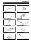
Periodic maintenance 2-15 special tools inside circlip pliers: 57001-143 steering stem nut wrench: 57001-1100 jack: 57001-1238 oil filter wrench: 57001-1249 tension gauge: 57001-1585.
Page 46: 2-16 Periodic Maintenance
2-16 periodic maintenance periodic maintenance procedures fuel system (dfi) throttle control system inspection • check the throttle grip free play [a]. Throttle grip free play standard: 2 ∼ 3 mm (0.08 ∼ 0.12 in.) if the free play is incorrect, adjust the throttle grip free play as follows. • slide t...
Page 47: Periodic Maintenance 2-17
Periodic maintenance 2-17 periodic maintenance procedures idle speed inspection • start the engine and warm it up thoroughly. ○ at first the engine will run fast to decrease warm up time (fast idle). ○ gradually the fast idle will lower to a certain rpm auto- matically. This is the idle speed. • wit...
Page 48: 2-18 Periodic Maintenance
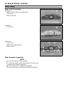
2-18 periodic maintenance periodic maintenance procedures • push the “s” button [a] of the right handlebar switch hous- ing for more than two seconds to display the clock setting mode [b] on the lcd (liquid crystal display)..
Page 49: Periodic Maintenance 2-19
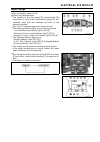
Periodic maintenance 2-19 periodic maintenance procedures • push the “s” button to display the idle speed adjusting mode [a]. Note ○ the display change to the clock setting mode [b], aver- age fuel consumption unit setting mode [c], idle speed adjusting mode each time the “s” button is pressed. ○ th...
Page 50: 2-20 Periodic Maintenance
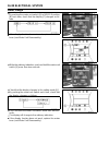
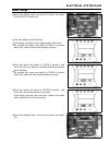
2-20 periodic maintenance periodic maintenance procedures ○ the idle speed goes up 50 r/min (rpm) at one time by pushing the “mode-a” switch. ○ when pushing the “mode-a” switch, the value on the display shows the “+50” [a] (this shows 1 000 r/min (rpm)). ○ the idle speed goes down 50 r/min (rpm) at ...
Page 51: Periodic Maintenance 2-21
Periodic maintenance 2-21 periodic maintenance procedures • check that the fuel hose [a] are routed according to cable, wire, and hose routing section in the appendix chapter. Replace the hose if it has been sharply bent or kinked. • check that the fuel hose joints are securely connected. ○ push and...
Page 52: 2-22 Periodic Maintenance
2-22 periodic maintenance periodic maintenance procedures • check the liquid/vapor separator as follows. ○ remove: canister (see evaporative emission control system in- spection (cal and sea models)) band [a] ○ disconnect the hoses from the separator [b], and remove the separator. ○ visually inspect...
Page 53: Periodic Maintenance 2-23
Periodic maintenance 2-23 periodic maintenance procedures radiator hose and pipe inspection (coolant leak, damage, installation condition) ○ the high pressure inside the radiator hose can cause coolant to leak [a] or the hose to burst if the line is not properly maintained. Visually inspect the hose...
Page 54: 2-24 Periodic Maintenance
2-24 periodic maintenance periodic maintenance procedures clutch clutch operation inspection • start the engine and check that the clutch does not slip and that it releases properly. If the clutch operation is insufficiency, inspect the clutch system. Warning when test riding the vehicle, be aware o...
Page 55: Periodic Maintenance 2-25
Periodic maintenance 2-25 periodic maintenance procedures clutch hose and pipe damage and installation condition inspection • the high pressure inside the clutch line can cause fluid to leak [a] or the hose to burst if the line is not properly maintained. Bend and twist the rubber hose while exam- i...
Page 56: 2-26 Periodic Maintenance
2-26 periodic maintenance periodic maintenance procedures • measure the tread depth at the center of the tread with a depth gauge [a]. Since the tire may wear unevenly, take measurement at several places. If any measurement is less than the service limit, replace the tire (see tire removal/installat...
Page 57: Periodic Maintenance 2-27
Periodic maintenance 2-27 periodic maintenance procedures final drive drive belt deflection inspection note ○ belt deflection must be checked and adjusted when the belt is cold (at room temperature). ○ belt deflection also should be checked at first 1000 km (621.4 mile) ride after belt replacement. ...
Page 58: 2-28 Periodic Maintenance
2-28 periodic maintenance periodic maintenance procedures • inspect the drive belt deflection at arbitrary position, and record the value [a]. • turn the rear wheel 90 degrees. • inspect the drive belt deflection, and record the value [b]. • decide the belt deflection at the position [c] of one wher...
Page 59: Periodic Maintenance 2-29
Periodic maintenance 2-29 periodic maintenance procedures • remove the axle cotter pin [a], and loosen the axle nut [b]. • raise the rear wheel off the ground (see rear wheel re- moval in the wheels/tires chapter). • loosen the belt adjuster locknuts [c] on the both sides. If the belt is too tight, ...
Page 60: 2-30 Periodic Maintenance
2-30 periodic maintenance periodic maintenance procedures wheel alignment inspection/adjustment • check that the notch [a] on the belt adjuster [b] aligns with the same swingarm mark [c] or position that the other side notch aligns with. If they do not, adjust the belt deflection (see belt deflec- t...
Page 61: Periodic Maintenance 2-31
Periodic maintenance 2-31 periodic maintenance procedures drive belt tooth wear and damage patterns a. Belt cross section b. Edge bevel wear c. Rub wear d. Stone.
Page 62: 2-32 Periodic Maintenance
2-32 periodic maintenance periodic maintenance procedures drive belt wear and damage analysis pattern condition required action 1 internal tooth cracks (slight) o.K. For continued use, but inspect the belt periodically. 2 scuffing to side of teeth o.K. For continued use, but inspect the belt periodi...
Page 63: Periodic Maintenance 2-33
Periodic maintenance 2-33 periodic maintenance procedures brakes brake fluid leak (brake hose and pipe) inspection • for k-act abs equipped models; note the following. • remove: fuel tank (see fuel tank removal in the fuel system (dfi) chapter) right side cover (see right side cover removal in the f...
Page 64: 2-34 Periodic Maintenance
2-34 periodic maintenance periodic maintenance procedures brake hose and pipe damage and installation condition inspection • for k-act abs equipped models; note the following. • remove: fuel tank (see fuel tank removal in the fuel system (dfi) chapter) right side cover (see right side cover removal ...
Page 65: Periodic Maintenance 2-35
Periodic maintenance 2-35 periodic maintenance procedures if the fluid level is lower than the lower level line, fill the reservoir to the upper level line [a] in the reservoir [b]. • check that the brake fluid level in the rear brake reservoir [a] is above the lower level line [b]. If the fluid lev...
Page 66: 2-36 Periodic Maintenance
2-36 periodic maintenance periodic maintenance procedures brake pad wear inspection • remove the brake pads (see front/rear brake pad re- moval in the brakes chapter). • check the lining thickness [a] of the pads in each caliper. If the lining thickness of either pad is less than the service limit [...
Page 67: Periodic Maintenance 2-37
Periodic maintenance 2-37 periodic maintenance procedures if it does not go on, inspect or replace the following items. Battery (see charging condition inspection in the elec- trical system chapter) brake light (led) (see tail/brake light (led) removal in the electrical system chapter) high mount br...
Page 68: 2-38 Periodic Maintenance
2-38 periodic maintenance periodic maintenance procedures rear shock absorber oil leak inspection • visually inspect the shock absorber [a] for oil leakage. If the oil leakage is found on it, replace the shock absorber with a new one. Swingarm pivot lubrication • remove the swingarm (see swingarm re...
Page 69: Periodic Maintenance 2-39
Periodic maintenance 2-39 periodic maintenance procedures • remove: bolt [a] holder [b] • remove the handlebar (see handlebar removal in the steering chapter). Notice take care not to bend the hoses sharply. • loosen the upper front fork clamp bolts [a]. • remove: steering stem head nut [b] and wash...
Page 70: 2-40 Periodic Maintenance
2-40 periodic maintenance periodic maintenance procedures • install the steering stem head. • tighten: torque - steering stem head nut: 108 n·m (11.0 kgf·m, 80 ft·lb) upper front fork clamp bolts: 20 n·m (2.0 kgf·m, 15 ft·lb) • install: handlebar (see handlebar installation in the steering chapter) ...
Page 71: Periodic Maintenance 2-41
Periodic maintenance 2-41 periodic maintenance procedures lights and switches operation first step • turn the ignition switch on. • the following lights should go on according to below table. Models united states canada europe aus- tralia position lights [a] go on go on – – city light [b] – – goes o...
Page 72: 2-42 Periodic Maintenance
2-42 periodic maintenance periodic maintenance procedures tail/brake light (led) and high mount tail/brake light (led) (see taillight (led) replacement in the electrical system chapter) license plate light bulb (see license plate light bulb replacement in the electrical system chapter) ecu (see ecu ...
Page 73: Periodic Maintenance 2-43
Periodic maintenance 2-43 periodic maintenance procedures • push the hazard button [a]. • the left and right turn signal lights (front and rear) should flash. • the turn signal indicator lights (led) in the meter unit should flash. If the lights do not flash, inspect or replace the following parts. ...
Page 74: 2-44 Periodic Maintenance
2-44 periodic maintenance periodic maintenance procedures fourth step • set the dimmer switch to low beam position [a]. • start the engine. • the low beam headlight should go on. If the low beam headlight does not go on, inspect or re- place the following parts. Headlight bulb (see headlight bulb re...
Page 75: Periodic Maintenance 2-45
Periodic maintenance 2-45 periodic maintenance procedures • pull out the projections [a] from the grommets [b] and remove the headlight cover [c]. • turn the horizontal adjuster [a] on the headlight with a screwdriver in or out until the beam points straight ahead. ○ turn the adjuster clockwise to f...
Page 76: 2-46 Periodic Maintenance
2-46 periodic maintenance periodic maintenance procedures • insert the projections [a] into the grommets [b] and install the headlight cover [c]. Sidestand switch operation inspection • raise the rear wheel off the ground with the jack (see rear wheel removal in the wheels/tires chapter). • inspect ...
Page 77: Periodic Maintenance 2-47
Periodic maintenance 2-47 periodic maintenance procedures starter relay (see starter relay inspection in the elec- trical system chapter) relay box (see relay circuit inspection in the electrical system chapter) harness (see wiring inspection in the electrical system chapter) if the all parts are go...
Page 78: 2-48 Periodic Maintenance
2-48 periodic maintenance periodic maintenance procedures points: lubricate with grease. Throttle inner cable upper and lower ends [a] cables: lubricate with rust inhibitor throttle cables • lubricate the cables by seeping the oil between the cable and housing. ○ the cable may be lubricated by using...
Page 79: Periodic Maintenance 2-49
Periodic maintenance 2-49 periodic maintenance procedures bolt, nut and fastener to be checked engine: radiator bolt exhaust pipe holder nuts left and right muffler body mounting bolts clutch lever pivot bolt and nut clutch master cylinder clamp bolts clutch slave cylinder bolts engine mounting bolt...
Page 80: 2-50 Periodic Maintenance
2-50 periodic maintenance periodic maintenance procedures replacement parts air cleaner element replacement note ○ in dusty areas, the element should be replaced more frequently than the recommended interval. Warning if dirt or dust is allowed to pass through into the throttle body assy, the throttl...
Page 81: Periodic Maintenance 2-51
Periodic maintenance 2-51 periodic maintenance procedures • tighten: torque - left air cleaner housing cover bolts : 4.9 n·m ( 0.50 kgf·m, 43 in·lb) l = 10 mm (0.39 in.) [a] l = 25 mm (0.98 in.) [b] fuel hose replacement • remove the fuel tank (see fuel tank removal in the fuel system (dfi) chapter)...
Page 82: 2-52 Periodic Maintenance
2-52 periodic maintenance periodic maintenance procedures coolant change warning coolant can be extremely hot and cause severe burns, is toxic and very slippery. Do not remove the radiator cap or attempt to change the coolant when the engine is hot; allow it cool completely. Immediately wipe any spi...
Page 83: Periodic Maintenance 2-53
Periodic maintenance 2-53 periodic maintenance procedures water and coolant mixture ratio (recommended) soft water : 50% coolant : 50% freezing point : –35°c (–31°f) total amount : 2.4 l (2.5 us qt) • fill the coolant into the radiator. Note ○ choose a suitable mixture ratio by referring to the cool...
Page 84: 2-54 Periodic Maintenance
2-54 periodic maintenance periodic maintenance procedures radiator hose and o-ring replacement • drain the coolant (see coolant change). • remove: thermostat housing [a] with bracket [b] (see thermo- stat removal in the cooling system chapter) alternator cover (see alternator removal in the electri-...
Page 85: Periodic Maintenance 2-55
Periodic maintenance 2-55 periodic maintenance procedures engine oil change • situate the motorcycle so that it is vertical after warming up the engine. • remove the oil filler cap [a] on the alternator cover. • remove the front [a] and rear [b] engine oil drain plugs and drain the oil. ○ the oil in...
Page 86: 2-56 Periodic Maintenance
2-56 periodic maintenance periodic maintenance procedures oil filter replacement • drain the engine oil (see engine oil change). • remove the oil filter [a] with the oil filter wrench [b] and discard the oil filter. Special tool - oil filter wrench: 57001-1249 note ○ the filter has an oil filter byp...
Page 87: Periodic Maintenance 2-57
Periodic maintenance 2-57 periodic maintenance procedures brake hose replacement notice brake fluid quickly ruins painted plastic surfaces; any spilled fluid should be completely washed away immediately. • remove the right saddlebag (see saddlebag removal in the frame chapter). • remove the brake ho...
Page 88: 2-58 Periodic Maintenance
2-58 periodic maintenance periodic maintenance procedures • for k-act abs equipped models, note the following. • remove: fuel tank (see fuel tank removal in the fuel system (dfi) chapter) right saddlebag (see saddlebag removal in the frame chapter) left muffler body (see muffler body removal in the ...
Page 89: Periodic Maintenance 2-59
Periodic maintenance 2-59 periodic maintenance procedures brake fluid change note ○ the procedure to change the front brake fluid is as fol- lows. Changing the rear brake fluid is the same as for the front brake. • level the brake fluid reservoir. • remove: screws [a] reservoir cap [b] diaphragm pla...
Page 90: 2-60 Periodic Maintenance
2-60 periodic maintenance periodic maintenance procedures • remove the rubber cap from the bleed valve [a] on the caliper [b]. • attach a clear plastic hose [c] to the bleed valve, and run the other end of the hose into a container. • fill the reservoir with fresh specified brake fluid. Note ○ for t...
Page 91: Periodic Maintenance 2-61
Periodic maintenance 2-61 periodic maintenance procedures • follow the procedure below to install the rear brake fluid reservoir cap correctly. ○ first, tighten the rear brake fluid reservoir cap [b] clock- wise [c] by hand until slight resistance is felt indicating that the cap is seated on the res...
Page 92: 2-62 Periodic Maintenance
2-62 periodic maintenance periodic maintenance procedures rear master cylinder disassembly • remove the rear master cylinder (see rear master cylin- der removal in the brakes chapter). • remove the reservoir cap [a], plate [b] and diaphragm [c]. • remove the circlip [d], connector [e] and o-ring [f]...
Page 93: Periodic Maintenance 2-63
Periodic maintenance 2-63 periodic maintenance procedures caliper rubber parts replacement front caliper disassembly • remove: front caliper (see front caliper removal in the brakes chapter) front brake pads (see front brake pad removal in the brakes chapter) • remove the front caliper assembly bolt...
Page 94: 2-64 Periodic Maintenance
2-64 periodic maintenance periodic maintenance procedures front caliper assembly • clean the caliper parts except for the pads. Notice for cleaning the parts, use only disc brake fluid, isopropyl alcohol, or ethyl alcohol. • install the bleed valve and rubber cap. Torque - bleed valves: 7.8 n·m (0.8...
Page 95: Periodic Maintenance 2-65
Periodic maintenance 2-65 periodic maintenance procedures • using compressed air, remove the pistons. One way to remove the pistons is as follows. ○ cover the caliper opening with a clean, heavy cloth [a]. ○ remove the piston by lightly applying compressed air [b] to where the brake line fits into t...
Page 96: 2-66 Periodic Maintenance
2-66 periodic maintenance periodic maintenance procedures • apply brake fluid to the outside of the pistons, and push them into each cylinder by hand . • replace the friction boot [a] and dust boot [b] with new ones. • apply silicone grease to the sliding surface of the caliper holder shafts [c]. • ...
Page 97: Periodic Maintenance 2-67
Periodic maintenance 2-67 periodic maintenance procedures • open the clamps [a] • pull out the clutch hose [b] from the holder [c]. • immediately wash away any clutch fluid that spills. • there are washers on each side of the clutch hose fittings. Replace them with new ones when installing. • tighte...
Page 98: 2-68 Periodic Maintenance
2-68 periodic maintenance periodic maintenance procedures clutch fluid change • level the clutch fluid reservoir and remove the reservoir cap. • remove the engine pulley outer cover (see engine pulley outer cover removal in the final drive chapter). • remove the rubber cap from the bleed valve on th...
Page 99: Periodic Maintenance 2-69
Periodic maintenance 2-69 periodic maintenance procedures clutch master cylinder rubber parts replacement • remove the clutch master cylinder (see clutch master cylinder removal in the clutch chapter). • remove the reservoir cap [a], plate [b] and diaphragm [c], and pour the clutch fluid into a cont...
Page 100: 2-70 Periodic Maintenance
2-70 periodic maintenance periodic maintenance procedures clutch slave cylinder piston seal replacement • remove the engine pulley outer cover (see engine pulley outer cover removal in the final drive). • loosen the banjo bolt [a] at the clutch pipe lower end, and tighten it loosely. • unscrew the s...
Page 101: Periodic Maintenance 2-71
Periodic maintenance 2-71 periodic maintenance procedures • remove the spark plug using a 14 mm (0.55 in.) plug wrench [a] vertically. Notice the insulator [a] of the spark plug may break if when the wrench is inclined during loosening. Inclined spark plug wrench [b] contact (spark plug and plug wre...
Page 103: Fuel System (Dfi) 3-1
Fuel system (dfi) 3-1 3 fuel system (dfi) table of contents exploded view........................................................................................................................ 3-4 specifications ..........................................................................................
Page 104: 3-2 Fuel System (Dfi)
3-2 fuel system (dfi) gear position switch output voltage inspection .............................................................. 3-63 vehicle-down sensor (service code 31)................................................................................ 3-65 vehicle-down sensor removal ...............
Page 105: Fuel System (Dfi) 3-3
Fuel system (dfi) 3-3 fuel pump operating voltage inspection ......................................................................... 3-95 pressure regulator removal............................................................................................ 3-96 fuel filter cleaning...................
Page 106: 3-4 Fuel System (Dfi)
3-4 fuel system (dfi) exploded view.
Page 107: Fuel System (Dfi) 3-5
Fuel system (dfi) 3-5 exploded view torque no. Fastener n·m kgf·m ft·lb remarks 1 air cleaner housing cover bolts 4.9 0.50 43 in·lb 2 air cleaner element bolt 4.9 0.50 43 in·lb 3 air cleaner housing bolts 9.8 1.0 87 in·lb 4 crankshaft sensor bolts 5.9 0.60 52 in·lb 5 delivery joint bolts 9.8 1.0 87 ...
Page 108: 3-6 Fuel System (Dfi)
3-6 fuel system (dfi) exploded view.
Page 109: Fuel System (Dfi) 3-7
Fuel system (dfi) 3-7 exploded view torque no. Fastener n·m kgf·m ft·lb remarks 1 oxygen sensor (equipped models) 25 2.5 18 2. Cal and sea models 3. Canister 4. Separator.
Page 110: 3-8 Fuel System (Dfi)
3-8 fuel system (dfi) specifications item standard digital fuel injection system idle speed 950 ±50 r/min (rpm) throttle body assy: type two barrel type bore 42 mm (1.65 in.) ecu: make mitsubishi electric type digital memory type, with built in ic igniter, sealed with resin fuel pressure (high press...
Page 111: Fuel System (Dfi) 3-9
Fuel system (dfi) 3-9 specifications item standard vehicle-down sensor: input voltage dc 4.75 ∼ 5.25 v output voltage with sensor tilted 40 ∼ 50° or more right or left: dc 0.65 ∼ 1.35 v with sensor arrow mark pointed up: dc 3.55 ∼ 4.45 v oxygen sensor (equipped models): output voltage (rich) dc 0.8 ...
Page 112: 3-10 Fuel System (Dfi)
3-10 fuel system (dfi) special tools and sealant oil pressure gauge, 5 kgf/cm²: 57001-125 jack: 57001-1238 fork oil level gauge: 57001-1290 vacuum gauge: 57001-1369 hand tester: 57001-1394 needle adapter set: 57001-1457 fuel pressure gauge adapter: 57001-1593 fuel hose: 57001-1607 speed sensor measu...
Page 113: Fuel System (Dfi) 3-11
Fuel system (dfi) 3-11 special tools and sealant liquid gasket, tb1211: 56019-120
Page 114: 3-12 Fuel System (Dfi)
3-12 fuel system (dfi) dfi system dfi system.
Page 115: Fuel System (Dfi) 3-13
Fuel system (dfi) 3-13 dfi system 1. Fuel tank 2. Fi indicator led light 3. Ecu 4. Battery 12 v 18 ah 5. Pressure regulator 6. Fuel pump 7. Water temperature sensor 8. Intake air pressure sensor 9. Delivery joint 10. Fuel injector #1 11. Fuel injector #2 12. Air switching valve 13. Intake air temper...
Page 116: 3-14 Fuel System (Dfi)
3-14 fuel system (dfi) dfi system dfi system wiring diagram.
Page 117: Fuel System (Dfi) 3-15
Fuel system (dfi) 3-15 dfi system part names 1. Ecu 2. Oxygen sensor (equipped models) 3. Speed sensor 4. Gear position switch 5. Etv actuator relay 6. Throttle position sensor/etv actuator 7. Etv actuator 8. Throttle position sensor 2 9. Throttle position sensor 1 10. Accelerator position sensor 11...
Page 118: 3-16 Fuel System (Dfi)
3-16 fuel system (dfi) dfi system terminal numbers of ecu connectors terminal names 1. Ignition coil #2 (rear cylinder): bk 2. Fuel injector #2 (rear cylinder): bl/y 3. Unused 4. Ground for etv actuator (to battery): bk/w 5. Power supply to etv actuator (from etv actuator relay): g/o 6. Etv actuator...
Page 119: Fuel System (Dfi) 3-17
Fuel system (dfi) 3-17 dfi system 35. Battery monitor voltage: w/r 36. Intake air temperature sensor: r 37. Unused 38. Crankshaft sensor (+): y 39. Speed sensor: lg/r 40. Gear position switch: g 41. Unused 42. Unused 43. Power supply to accelerator position sensor 2: bl/bk 44. Power supply to ecu (f...
Page 120: 3-18 Fuel System (Dfi)
3-18 fuel system (dfi) dfi parts location ignition coil #1 (front cylinder) [a] air switching valve [b] ignition coil #2 (rear cylinder) [a] intake air pressure sensor [b] water temperature sensor [a] fuel injector #1 (front cylinder) [b] fuel injector #2 (rear cylinder) [c] intake air temperature s...
Page 121: Fuel System (Dfi) 3-19
Fuel system (dfi) 3-19 dfi parts location gear position switch [a] speed sensor [a] kawasaki diagnostic system connector (6-pin connec- tor) [b] etv actuator relay [a] (r/bl, y/bl, r/bl, g/o leads) vehicle-down sensor [b] fuse box 2 [c] (ecu fuse 10 a, etv actuator relay fuse 10 a, oxygen sensor hea...
Page 122: 3-20 Fuel System (Dfi)
3-20 fuel system (dfi) dfi servicing precautions dfi servicing precautions there are a number of important precautions that should be followed servicing the dfi system. ○ this dfi system is designed to be used with a 12 v sealed battery as its power source. Do not use any other battery except for a ...
Page 123: Fuel System (Dfi) 3-21
Fuel system (dfi) 3-21 dfi servicing precautions ○ if the motorcycle is not properly handled, the high pres- sure inside the fuel line can cause fuel to leak or the hose to burst. Remove the fuel tank (see fuel tank removal) and check the fuel hose [a]. Replace the fuel hose if any fraying, cracks o...
Page 124: 3-22 Fuel System (Dfi)
3-22 fuel system (dfi) troubleshooting the dfi system the warning indicator light (led) [a] is used for the fi/etv (electronic throttle valve) indicator, oil pressure warning indicator and battery low voltage warning indicator. Outline when problem occurs with dfi system, the warning indi- cator lig...
Page 125: Fuel System (Dfi) 3-23
Fuel system (dfi) 3-23 troubleshooting the dfi system when the service code [a] is displayed, for first ask the rider about the conditions [b] of trouble, and then start to determine the cause [c] of problem. As a pre-diagnosis inspection, check the ecu for ground and power supply, the fuel line for...
Page 126: 3-24 Fuel System (Dfi)
3-24 fuel system (dfi) troubleshooting the dfi system • when checking the dfi parts, use a digital meter which can be read two decimal place voltage or resistance. ○ the dfi part connectors [a] have seals [b], including the ecu. • when measuring the input or output voltage with the con- nector joine...
Page 127: Fuel System (Dfi) 3-25
Fuel system (dfi) 3-25 troubleshooting the dfi system • pull each connector [a] apart and inspect it for corrosion, dirt, and damage. If the connector is corroded or dirty, clean it carefully. If it is damaged, replace it. Connect the connectors securely. • check the wiring for continuity. ○ use the...
Page 128: 3-26 Fuel System (Dfi)
3-26 fuel system (dfi) troubleshooting the dfi system dfi diagnosis flow chart inquiries to rider ○ each rider reacts to problems in different ways, so it is important to confirm what kind of symptoms the rider has encountered. ○ try to find out exactly what problem occurred under exactly what condi...
Page 129: Fuel System (Dfi) 3-27
Fuel system (dfi) 3-27 troubleshooting the dfi system sample diagnosis sheet rider name: registration no. (license plate no.): year of initial registration: model: engine no.: frame no.: date problem occurred: mileage: environment when problem occurred. Weather □ fine, □ cloudy, □ rain, □ snow, □ al...
Page 130: 3-28 Fuel System (Dfi)
3-28 fuel system (dfi) troubleshooting the dfi system □ spark plug loose (tighten it). □ spark plug dirty, broken, or gap maladjusted (remedy it). □ spark plug incorrect (replace it). □ knocking (fuel poor quality or incorrect, → use high-octane gasoline). □ brake dragging. □ clutch slipping. □ engi...
Page 131: Fuel System (Dfi) 3-29
Fuel system (dfi) 3-29 dfi system troubleshooting guide note ○ this is not an exhaustive list, giving every possible cause for each problem listed. It is meant simply as a rough guide to assist the troubleshooting for some of the more common difficulties in dfi system. ○ the ecu may be involved in t...
Page 132: 3-30 Fuel System (Dfi)
3-30 fuel system (dfi) dfi system troubleshooting guide symptoms or possible causes actions (chapter) fuel pressure regulator trouble inspect fuel pressure and replace fuel pump (see chapter 3). Fuel line clogged inspect and repair (see chapter 3). Intake air pressure sensor trouble inspect (see cha...
Page 133: Fuel System (Dfi) 3-31
Fuel system (dfi) 3-31 dfi system troubleshooting guide symptoms or possible causes actions (chapter) intake air temperature sensor trouble inspect (see chapter 3). Spark plug dirty, broken or gap maladjusted inspect and replace (see chapter 2). Ignition coil trouble inspect (see chapter 16). Stumbl...
Page 134: 3-32 Fuel System (Dfi)
3-32 fuel system (dfi) dfi system troubleshooting guide symptoms or possible causes actions (chapter) ignition coil trouble inspect (see chapter 16). Spark plug dirty, broken or gap maladjusted inspect and replace (see chapter 2). Spark plug incorrect replace it with the correct plug (see chapter 2)...
Page 135: Fuel System (Dfi) 3-33
Fuel system (dfi) 3-33 dfi system troubleshooting guide symptoms or possible causes actions (chapter) air cleaner element clogged clean element (see chapter 2). Fuel pressure too high inspect (see chapter 3). Fuel injector trouble inspect (see chapter 3). Water temperature sensor trouble inspect (se...
Page 136: 3-34 Fuel System (Dfi)
3-34 fuel system (dfi) self-diagnosis the warning indicator light (led) [a] is used for the fi/etv (electronic throttle valve) indicator, oil pressure warning indicator and battery low voltage warning indicator. Self-diagnosis outline the ecu notifies the rider of troubles in dfi system, ig- nition ...
Page 137: Fuel System (Dfi) 3-35
Fuel system (dfi) 3-35 self-diagnosis • turn the ignition switch on. • the service code [a] is displayed by the number of two digits. • when pushing the “s” button [b] of the right handlebar switch housing for more than two seconds while the “er- ror” segments [c], service code and fi warning symbol...
Page 138: 3-36 Fuel System (Dfi)
3-36 fuel system (dfi) self-diagnosis self-diagnosis flow chart.
Page 139: Fuel System (Dfi) 3-37
Fuel system (dfi) 3-37 self-diagnosis service code reading ○ the service code(s) is displayed on the lcd by the number of two digits. ○ when there are a number of problems, all the service codes can be stored and the display will begin starting from the lowest number service code in the numerical or...
Page 140: 3-38 Fuel System (Dfi)
3-38 fuel system (dfi) self-diagnosis service code table service code system problems 11 etv throttle position sensor malfunction, wiring open or short. 12 dfi intake air pressure sensor malfunction, wiring open or short. 13 dfi intake air temperature sensor malfunction, wiring open or short. 14 dfi...
Page 141: Fuel System (Dfi) 3-39
Fuel system (dfi) 3-39 self-diagnosis backups ○ the ecu takes the following measures to prevent engine damage when the dfi, ignition or etv system parts have troubles. Service codes parts output signal usable range or criteria backups by ecu 11 throttle position sensor output voltage (full throttle ...
Page 142: 3-40 Fuel System (Dfi)
3-40 fuel system (dfi) self-diagnosis service codes parts output signal usable range or criteria backups by ecu 51 ignition coil #1 (front cylinder) – if the ignition coil #1 primary winding has failures (wiring short or open), the ecu shuts off the injector #1 to stop fuel to the cylinder #1, thoug...
Page 143: Fuel System (Dfi) 3-41
Fuel system (dfi) 3-41 throttle position sensor (service code 11) throttle position sensor removal notice do not remove throttle position sensor in the gear case [a] since it has been adjusted and set with pre- cision at the factory. Never drop the throttle body assy, especially on a hard surface. S...
Page 144: 3-42 Fuel System (Dfi)
3-42 fuel system (dfi) throttle position sensor (service code 11) throttle position sensor input voltage inspection note ○ be sure the battery is fully charged. • turn the ignition switch off. • remove: front seat (see front seat removal in the frame chap- ter) battery case cover (see battery remova...
Page 145: Fuel System (Dfi) 3-43
Fuel system (dfi) 3-43 throttle position sensor (service code 11) throttle position sensor circuit 1. Ecu 2. Throttle position sensor/etv actuator 3. Throttle position sensor 1 4. Throttle position sensor 2.
Page 146: 3-44 Fuel System (Dfi)
3-44 fuel system (dfi) intake air pressure sensor (service code 12) intake air pressure sensor removal notice never drop the intake air pressure sensor, espe- cially on a hard surface. Such a shock to the sensor can damage it. • remove: fuel tank (see fuel tank removal) intake air pressure sensor co...
Page 147: Fuel System (Dfi) 3-45
Fuel system (dfi) 3-45 intake air pressure sensor (service code 12) if the reading is out of the standard, remove the ecu and check the wiring for continuity between main harness connectors. Special tool - hand tester: 57001-1394 ○ disconnect the ecu and sensor connectors. Wiring continuity inspecti...
Page 148: 3-46 Fuel System (Dfi)
3-46 fuel system (dfi) intake air pressure sensor (service code 12) if the reading is within the usable range, remove the ecu and check the wiring for continuity between main harness connector. Special tool - hand tester: 57001-1394 ○ disconnect the ecu and sensor connectors. Wiring continuity inspe...
Page 149: Fuel System (Dfi) 3-47
Fuel system (dfi) 3-47 intake air pressure sensor (service code 12) then pv = pl – pg for example, suppose the following data is obtained: pg = 8 cmhg (vacuum gauge reading) pl = 70 cmhg (barometer reading) vv = 3.2 v (digital meter reading) then pv = 70 – 8 = 62 cmhg (absolute) plot this pv (62 cmh...
Page 150: 3-48 Fuel System (Dfi)
3-48 fuel system (dfi) intake air pressure sensor (service code 12) id: idling ps: standard atmospheric pressure (absolute) pv: throttle vacuum pressure (absolute) st: standard of sensor output voltage (v) to: throttle full open ur: usable range of sensor output voltage (v) vv: intake air pressure s...
Page 151: Fuel System (Dfi) 3-49
Fuel system (dfi) 3-49 intake air pressure sensor (service code 12) intake air pressure sensor circuit 1. Ecu 2. Intake air pressure sensor.
Page 152: 3-50 Fuel System (Dfi)
3-50 fuel system (dfi) intake air temperature sensor (service code 13) intake air temperature sensor removal/instal- lation notice never drop the intake air temperature sensor, espe- cially on a hard surface. Such a shock to the sensor can damage it. • remove: right air cleaner housing (see air clea...
Page 153: Fuel System (Dfi) 3-51
Fuel system (dfi) 3-51 intake air temperature sensor (service code 13) • turn the ignition switch off. If the reading is within the standard, check the ecu for its ground and power supply (see ecu power supply in- spection). If the ground and power supply are good, replace the ecu (see ecu removal/i...
Page 154: 3-52 Fuel System (Dfi)
3-52 fuel system (dfi) intake air temperature sensor (service code 13) intake air temperature sensor circuit 1. Ecu 2. Intake air temperature sensor.
Page 155: Fuel System (Dfi) 3-53
Fuel system (dfi) 3-53 water temperature sensor (service code 14) water temperature sensor removal/installation notice never drop the water temperature sensor, espe- cially on a hard surface. Such a shock to the sensor can damage it. • remove: fuel tank (see fuel tank removal) • drain the coolant (s...
Page 156: 3-54 Fuel System (Dfi)
3-54 fuel system (dfi) water temperature sensor (service code 14) • turn the ignition switch off. If the reading is within the standard, check the ecu for its ground, and power supply (see ecu power supply inspection). If the ground and power supply are good, replace the ecu (see ecu removal/install...
Page 157: Fuel System (Dfi) 3-55
Fuel system (dfi) 3-55 accelerator position sensor (service code 18) accelerator position sensor removal notice do not remove accelerator position sensor [a] since it has been adjusted and set with precision at the factory. Never drop the throttle body assy, especially on a hard surface. Such a shoc...
Page 158: 3-56 Fuel System (Dfi)
3-56 fuel system (dfi) accelerator position sensor (service code 18) accelerator position sensor input voltage inspection note ○ be sure the battery is fully charged. • turn the ignition switch off. • remove: front seat (see front seat removal in the frame chap- ter) battery case cover (see battery ...
Page 159: Fuel System (Dfi) 3-57
Fuel system (dfi) 3-57 accelerator position sensor (service code 18) • connect the digital meter [a] to the terminals of the accel- erator position sensor connector [b]. Accelerator position sensor resistance connection: (1) bl/w lead terminal → bk/o lead terminal (2) bl/bk lead terminal → br lead t...
Page 160: 3-58 Fuel System (Dfi)
3-58 fuel system (dfi) crankshaft sensor (service code 21) the crankshaft sensor has no power source, and when the engine stops, the crankshaft sensor generates no sig- nals. Crankshaft sensor removal/installation • refer to the crankshaft sensor removal/installation in the electrical system chapter...
Page 161: Fuel System (Dfi) 3-59
Fuel system (dfi) 3-59 crankshaft sensor (service code 21) crankshaft sensor circuit 1. Ecu 2. Crankshaft sensor.
Page 162: 3-60 Fuel System (Dfi)
3-60 fuel system (dfi) speed sensor (service code 24) speed sensor removal/installation • refer to the speed sensor removal/installation in the electrical system chapter. Speed sensor input voltage inspection note ○ be sure the battery is fully charged. • turn the ignition switch off. • disconnect t...
Page 163: Fuel System (Dfi) 3-61
Fuel system (dfi) 3-61 speed sensor (service code 24) speed sensor output voltage inspection • using the jack, raise the rear wheel off the ground (see rear wheel removal in the wheels/tires chapter). Special tool - jack: 57001-1238 • measure the output voltage at the speed sensor in the same way as...
Page 164: 3-62 Fuel System (Dfi)
3-62 fuel system (dfi) speed sensor (service code 24) speed sensor circuit 1. Ecu 2. Speed sensor.
Page 165: Fuel System (Dfi) 3-63
Fuel system (dfi) 3-63 gear position switch (service code 25) gear position switch removal/installation • refer to the gear position switch removal/installation in the electrical system chapter. Gear position switch resistance inspection • refer to the gear position switch inspection in the elec- tr...
Page 166: 3-64 Fuel System (Dfi)
3-64 fuel system (dfi) gear position switch (service code 25) • turn the ignition switch off. If the reading is out of the standard, check the wiring for continuity, using the wiring diagram in this section. Special tool - hand tester: 57001-1394 if the wiring is good, check the ecu for its ground a...
Page 167: Fuel System (Dfi) 3-65
Fuel system (dfi) 3-65 vehicle-down sensor (service code 31) this sensor has a weight [a] with two magnets inside, and sends a signal to the ecu. But when the motorcycle banks 60 ∼ 70° or more to either side (in fact falls down), the weight turns and the signal changes. The ecu senses this change, a...
Page 168: 3-66 Fuel System (Dfi)
3-66 fuel system (dfi) vehicle-down sensor (service code 31) vehicle-down sensor input voltage inspection note ○ be sure the battery is fully charged. • remove the vehicle-down sensor (see vehicle-down sensor removal). • connect the measuring adapter [a] between the main har- ness connector and vehi...
Page 169: Fuel System (Dfi) 3-67
Fuel system (dfi) 3-67 vehicle-down sensor (service code 31) vehicle-down sensor output voltage inspection • measure the output voltage at the vehicle-down sensor in the same way as input voltage inspection, note the follow- ing. ○ connect the measuring adapter [a] between the main har- ness connect...
Page 170: 3-68 Fuel System (Dfi)
3-68 fuel system (dfi) vehicle-down sensor (service code 31) if the reading is within the standard, remove the ecu and check the wiring for continuity between main harness con- nectors. Special tool - hand tester: 57001-1394 ○ disconnect the ecu and sensor connectors. Wiring continuity inspection ec...
Page 171: Fuel System (Dfi) 3-69
Fuel system (dfi) 3-69 oxygen sensor - not activated (service code 33, equipped models) oxygen sensor removal/installation • refer to the oxygen sensor removal/installation (equipped models) in the electrical system chapter. Oxygen sensor inspection • warm up the engine thoroughly until the radiator...
Page 172: 3-70 Fuel System (Dfi)
3-70 fuel system (dfi) oxygen sensor - not activated (service code 33, equipped models) ○ do not disconnect the air switching valve connector [a]. • plug the air switching valve hose ends [a], and shut off the secondary air. • connect the following parts temporarily. Fuel pump/fuel level sensor lead...
Page 173: Fuel System (Dfi) 3-71
Fuel system (dfi) 3-71 oxygen sensor - not activated (service code 33, equipped models) if the reading is out of the standard (with plugs: 0.8 v or more, without plugs: 0.24 v or less), remove the ecu and check the wiring for continuity between main harness connectors. Special tool - hand tester: 57...
Page 174: 3-72 Fuel System (Dfi)
3-72 fuel system (dfi) fuel pump relay (service code 46) fuel pump relay removal/installation ○ the fuel pump relay is built in the relay box [a]. • refer to the relay box removal in the electrical system chapter. Fuel pump relay inspection • refer to the relay circuit inspection in the electrical s...
Page 175: Fuel System (Dfi) 3-73
Fuel system (dfi) 3-73 return spring (service code 49) return spring removal notice do not remove return spring in the gear case [a] since it has been set with precision at the factory. Return spring inspection • turn the ignition switch off. • remove right air cleaner housing (see right air cleaner...
Page 176: 3-74 Fuel System (Dfi)
3-74 fuel system (dfi) ignition coils #1, #2 (service code 51, 52) ignition coil #1 (front cylinder): service code 51 ignition coil #2 (rear cylinder): service code 52 ignition coil removal/installation • refer to the ignition coil removal/installation in the elec- trical system chapter. Ignition co...
Page 177: Fuel System (Dfi) 3-75
Fuel system (dfi) 3-75 ignition coils #1, #2 (service code 51, 52) ignition coil circuit 1. Ecu 2. Ignition coil #2 (rear cylinder) 3. Ignition coil #1 (front cylinder) 4. Engine stop switch 5. Ignition switch 6. Main fuse 30 a 7. Ignition fuse 10 a 8. Battery 9. Engine ground 10. Frame ground 3.
Page 178: 3-76 Fuel System (Dfi)
3-76 fuel system (dfi) radiator fan relay (service code 56) radiator fan relay removal/installation ○ the radiator fan relay is built in the relay box [a]. • refer to the relay box removal in the electrical system chapter. Radiator fan relay inspection • refer to the relay circuit inspection in the ...
Page 179: Fuel System (Dfi) 3-77
Fuel system (dfi) 3-77 etv acutuator (service code 58) etv actuator removal notice do not remove etv actuator in the gear case [a] since it has been set with precision at the factory. Etv actuator input voltage inspection note ○ be sure the battery is fully charged. • turn the ignition switch off. •...
Page 180: 3-78 Fuel System (Dfi)
3-78 fuel system (dfi) etv acutuator (service code 58) etv actuator relay inspection • remove: front seat (see front seat removal in the frame chap- ter) etv actuator relay [a] • connect the hand tester [a] and a 12 v battery [b] to the relay [c] as shown. Special tool - hand tester: 57001-1394 if t...
Page 181: Fuel System (Dfi) 3-79
Fuel system (dfi) 3-79 air switching valve (service code 64) air switching valve removal/installation • refer to the air switching valve removal/installation in the engine top end chapter. Air switching valve inspection • refer to the air switching valve unit test in the electrical system chapter. I...
Page 182: 3-80 Fuel System (Dfi)
3-80 fuel system (dfi) oxygen sensor heater (service code 67, equipped models) oxygen sensor heater removal/installation the oxygen sensor heater is built in the oxygen sensor. So, the heater itself cannot be removed. Remove the oxy- gen sensor (see oxygen sensor removal (equipped mod- els) in the e...
Page 183: Fuel System (Dfi) 3-81
Fuel system (dfi) 3-81 oxygen sensor heater (service code 67, equipped models) oxygen sensor heater power source voltage inspection note ○ be sure the battery is fully charged. • turn the ignition switch off. • disconnect the oxygen sensor lead connector and con- nect the measuring adapter [a] betwe...
Page 184: 3-82 Fuel System (Dfi)
3-82 fuel system (dfi) oxygen sensor heater (service code 67, equipped models) oxygen sensor circuit 1. Ecu 2. Oxygen sensor 3. Oxygen sensor heater fuse 10 a 4. Ignition switch 5. Main fuse 30 a 6. Battery 7. Engine ground.
Page 185: Fuel System (Dfi) 3-83
Fuel system (dfi) 3-83 battery voltage (service code 97) battery voltage inspection • refer to the charging condition inspection in the electri- cal system chapter for battery voltage inspection. If the battery voltage is good condition, replace the ecu (see ecu removal/installation). Battery monito...
Page 186: 3-84 Fuel System (Dfi)
3-84 fuel system (dfi) etv control circuit (service code 98) etv control circuit inspection ○ the etv control circuit is controlled in the ecu [a]. So, the etv control circuit cannot be inspected. • when the service code 98 is displayed on the lcd, re- place the ecu (see ecu removal/installation)..
Page 187: Fuel System (Dfi) 3-85
Fuel system (dfi) 3-85 warning indicator light (led) light (led) inspection ○ the warning indicator light (led) [a] is used for the fi in- dicator, etv (electronic throttle valve) indicator, oil pres- sure warning indicator and battery warning indicator. ○ in this model, the warning indicator light ...
Page 188: 3-86 Fuel System (Dfi)
3-86 fuel system (dfi) ecu ecu identification ○ most countries have their own regulations, so each ecu has different characteristic. So, do not confuse ecu with each other and use only the ecu for your model. Other- wise, the motorcycle cannot clear the regulation. Ecu identification model part numb...
Page 189: Fuel System (Dfi) 3-87
Fuel system (dfi) 3-87 ecu ecu installation • install: ecu (in rubber protector) ecu connectors • fit the hooks [a] of the bracket [b] into the recesses [c] of the battery case. • install the removed parts. Note ○ when the ecu was replaced with a new one, do not remove the battery, fuse or ecu for 6...
Page 190: 3-88 Fuel System (Dfi)
3-88 fuel system (dfi) ecu if the wiring is good, check the power source voltage of the ecu. Note ○ be sure the battery is fully charged. • connect the ecu connectors. • connect a digital meter [a] to the connector [b] with the needle adapter set. Special tool - needle adapter set: 57001-1457 ecu po...
Page 191: Fuel System (Dfi) 3-89
Fuel system (dfi) 3-89 ecu ecu power source circuit 1. Ignition switch 2. Ignition fuse 10 a 3. Ecu fuse 10 a 4. Main fuse 30 a 5. Battery 6. Engine ground 7. Frame ground 3 8. Frame ground 7 9. Ecu.
Page 192: 3-90 Fuel System (Dfi)
3-90 fuel system (dfi) dfi power source ecu fuse removal • refer to the 10 a ecu fuse removal in the electrical system chapter. Ecu fuse installation if a fuse fails during operation, inspect the dfi system to determine the cause, and then replace it with a new fuse of proper amperage. • refer to th...
Page 193: Fuel System (Dfi) 3-91
Fuel system (dfi) 3-91 fuel line fuel pressure inspection note ○ be sure the battery is fully charged. • remove: fuel hose (see fuel hose replacement in the periodic maintenance chapter) ○ be sure to place a piece of cloth around the fuel outlet pipe of the fuel pump and the delivery pipe of the thr...
Page 194: 3-92 Fuel System (Dfi)
3-92 fuel system (dfi) fuel line note ○ the gauge needle will fluctuate. Read the pressure at the average of the maximum and minimum indications. • turn the ignition switch off. If the fuel pressure is much higher than specified, replace the fuel pump because the fuel pressure regulator in the fuel ...
Page 195: Fuel System (Dfi) 3-93
Fuel system (dfi) 3-93 fuel line • connect the prepared fuel hose [a] to the fuel outlet pipe. • secure the fuel hose with a clamp. • insert the fuel hose into the measuring cylinder [b]. Warning wipe off spilled out fuel immediately. Be sure to hold the measuring cylinder vertical. • close the fuel...
Page 196: 3-94 Fuel System (Dfi)
3-94 fuel system (dfi) fuel pump fuel pump removal warning gasoline is extremely flammable and can be ex- plosive under certain conditions, creating the potential for serious burns. Make sure the area is well-ventilated and free from any source of flame or sparks; this includes any appliance with a ...
Page 197: Fuel System (Dfi) 3-95
Fuel system (dfi) 3-95 fuel pump fuel pump installation • remove dirt or dust from the fuel pump [a] by lightly ap- plying compressed air. • replace the fuel pump gasket with a new one. • check that the fuel pump terminal [a] and band [b] are in place. 200 ±10 mm (7.87 ±0.39 in.) [c] connector [d] f...
Page 198: 3-96 Fuel System (Dfi)
3-96 fuel system (dfi) fuel pump • disconnect the fuel pump lead connector and connect the measuring adapter [a] between these connectors as shown. Main harness [b] fuel pump [c] special tool - measuring adapter: 57001-1700 • connect a digital meter [d] to the measuring adapter leads. Fuel pump oper...
Page 199: Fuel System (Dfi) 3-97
Fuel system (dfi) 3-97 fuel pump fuel filter cleaning ○ the fuel filter [a] is built into the pump and cannot be cleaned or checked. If the fuel filter is suspected of clogging or being damaged, replace it with the fuel pump as a set. Fuel pump circuit 1. Ecu 2. Engine stop switch 3. Ignition switch...
Page 200: 3-98 Fuel System (Dfi)
3-98 fuel system (dfi) fuel injectors fuel injector removal • remove: fuel tank (see fuel tank removal) throttle body assy (see throttle body assy removal) fuel injector connectors [a] • remove: delivery joint bolt [a] bracket [b] • remove: delivery joint bolt [a] bracket [b] • remove: delivery join...
Page 201: Fuel System (Dfi) 3-99
Fuel system (dfi) 3-99 fuel injectors fuel injector installation • before installing the fuel injector, blow away dirt or dust from the delivery joint by applying compressed air. • replace the o-rings [a] of each fuel injector with new ones. • apply engine oil to the new o-rings, insert them to the ...
Page 202: 3-100 Fuel System (Dfi)
3-100 fuel system (dfi) fuel injectors • connect the digital meter [a] to the harness connectors [b] with the needle adapter set. Special tool - needle adapter set: 57001-1457 fuel injector resistance connection: fuel injector #1 digital meter → bl/o lead (ecu terminal 27) digital meter → w/r lead (...
Page 203: Fuel System (Dfi) 3-101
Fuel system (dfi) 3-101 fuel injectors • turn the ignition switch off. If the reading is in the specification, but the injector does not operate, replace the ecu (see ecu removal/instal- lation). If the reading is out of the specification, check the input voltage (see fuel injector input voltage ins...
Page 204: 3-102 Fuel System (Dfi)
3-102 fuel system (dfi) fuel injectors fuel injector fuel line inspection • remove: fuel tank (see fuel tank removal) left air cleaner housing (see left air cleaner housing removal) fuel hoses (see fuel hose replacement in the periodic maintenance chapter) ○ be sure to place a piece of cloth around ...
Page 205: Fuel System (Dfi) 3-103
Fuel system (dfi) 3-103 fuel injectors fuel injector circuit 1. Ecu 2. Engine stop switch 3. Fuel injector #2 4. Fuel injector #1 5. Ignition switch 6. Ignition fuse 10 a 7. Ecu fuse 10 a 8. Main fuse 30 a 9. Battery 10. Engine ground 11. Relay box 12. Fuel pump relay 13. Frame ground 3.
Page 206: 3-104 Fuel System (Dfi)
3-104 fuel system (dfi) throttle grip and cables free play inspection • refer to the throttle control system inspection in the pe- riodic maintenance chapter. Free play adjustment • refer to the throttle control system inspection in the pe- riodic maintenance chapter. Cable installation • install th...
Page 207: Fuel System (Dfi) 3-105
Fuel system (dfi) 3-105 throttle grip and cables if the stopper of the pulley does not touch, adjust the throttle grip free play with the accelerator cable adjuster [a] and then use the decelerator cable adjuster [b] (see throttle control system inspection in the periodic main- tenance chapter). • c...
Page 208: 3-106 Fuel System (Dfi)
3-106 fuel system (dfi) throttle body assy idle speed inspection/adjustment • refer to the idle speed inspection/adjustment in the pe- riodic maintenance chapter. Throttle body assy removal warning gasoline is extremely flammable and can be ex- plosive under certain conditions, creating the potentia...
Page 209: Fuel System (Dfi) 3-107
Fuel system (dfi) 3-107 throttle body assy • remove: vacuum hose [a] electronic cruise control cancel switch (throttle) lead connector [b] • remove: throttle position sensor connector [a] accelerator position sensor connector [b] throttle body assy bolts [c] throttle body assy [d] (from intake manif...
Page 210: 3-108 Fuel System (Dfi)
3-108 fuel system (dfi) throttle body assy • apply a thin coat of grease to the throttle cable upper ends. • install the upper ends of the throttle cables in the grip. • fit the projection [a] of the right handlebar switch housing into the hole [b] of the handlebar. • install: right handlebar switch...
Page 211: Fuel System (Dfi) 3-109
Fuel system (dfi) 3-109 throttle body assy • install: throttle body assy [a] throttle body assy bolt [b], 75 mm (3.0 in.) throttle body assy bolts [c], 60 mm (2.4 in.) • tighten: torque - throttle body assy bolts: 9.8 n·m (1.0 kgf·m, 87 in·lb) • install: electronic cruise control cancel switch (thro...
Page 212: 3-110 Fuel System (Dfi)
3-110 fuel system (dfi) throttle body assy throttle body assy assembly • apply a non-permanent locking agent to the threads of the electronic cruise control cancel switch (throttle) bolt [a]. • install the switch so that the projection [b] into the hole [c] of the bracket. • install: plane washer [a...
Page 213: Fuel System (Dfi) 3-111
Fuel system (dfi) 3-111 intake manifold intake manifold removal • remove: throttle body assy (see throttle body assy removal) fuel injectors (fuel injector removal) intake manifold bolts [a] intake manifold [b] intake manifold installation • wipe any carbon off the bores [a] around the intake man- i...
Page 214: 3-112 Fuel System (Dfi)
3-112 fuel system (dfi) air cleaner air cleaner element removal/installation • refer to the air cleaner element replacement in the pe- riodic maintenance chapter. Air cleaner element inspection • remove: air cleaner element (see air cleaner element replace- ment in the periodic maintenance chapter) ...
Page 215: Fuel System (Dfi) 3-113
Fuel system (dfi) 3-113 air cleaner • remove: breather hose [a] left air cleaner housing installation • when installing the damper [a] and collar [b], install them as shown. Air cleaner housing [c] engine side [d] big side [e] • insert the breather hose [a] into the grommet [b] as shown. ○ reach the...
Page 216: 3-114 Fuel System (Dfi)
3-114 fuel system (dfi) air cleaner • remove: right air cleaner housing cover bolts [a] right air cleaner housing cover [b] • remove: intake air temperature sensor connector [a] air switching valve hose [b] • remove: air cleaner housing bolts [a] washers (vn1700a9f/b9f models) right air cleaner hous...
Page 217: Fuel System (Dfi) 3-115
Fuel system (dfi) 3-115 air cleaner • install: right air cleaner housing washers (vn1700a9f/b9f models) air cleaner housing bolts [a] • apply a non-permanent locking agent to the right air cleaner housing center bolts [b]. • tighten: torque - right air cleaner housing center bolts: 9.8 n·m (1.0 kgf·...
Page 218: 3-116 Fuel System (Dfi)
3-116 fuel system (dfi) fuel tank fuel tank removal warning gasoline is extremely flammable and can be ex- plosive under certain conditions, creating the potential for serious burns. Make sure the area is well-ventilated and free from any source of flame or sparks; this includes any appliance with a...
Page 219: Fuel System (Dfi) 3-117
Fuel system (dfi) 3-117 fuel tank • remove: fuel tank bolts [a] bracket [b] • disconnect: fuel pump lead connector [a] • be sure to place a piece of cloth [a] around the fuel hose joint. • insert a thin blade screwdriver [b] into the slit [c] on the joint lock [d]. • turn [a] the driver to disconnec...
Page 220: 3-118 Fuel System (Dfi)
3-118 fuel system (dfi) fuel tank • for the california and southeast asia models, remove the following. Fuel return hose [a] (left side, red) • remove the fuel tank, and place it on a flat surface. ○ do not apply the load to the fuel outlet pipe of the fuel pump. • for the california and southeast a...
Page 221: Fuel System (Dfi) 3-119
Fuel system (dfi) 3-119 fuel tank fuel tank installation • note the above warning (see fuel tank removal). • run the hoses correctly (see cable, wire, and hose rout- ing section in the appendix chapter). • check that the dampers [a] are in place on the fuel tank. If the dampers are damaged or deteri...
Page 222: 3-120 Fuel System (Dfi)
3-120 fuel system (dfi) fuel tank • install [a] the fuel hose joint [b] straight onto the fuel outlet pipe until the hose joint clicks. • push [c] the joint lock [d] until the hose joint clicks. • push and pull [a] the fuel hose joint [b] back and forth more than two times, and make sure it is locke...
Page 223: Fuel System (Dfi) 3-121
Fuel system (dfi) 3-121 evaporative emission control system (cal and sea models) the evaporative emission control system routes fuel va- pors from the fuel system into the running engine or stores the vapors in a canister when the engine is stopped. Al- though no adjustments are required, a thorough...
Page 224: 3-122 Fuel System (Dfi)
3-122 fuel system (dfi) evaporative emission control system (cal and sea models) separator operation test warning gasoline is extremely flammable and can be ex- plosive under certain conditions. Turn the ignition switch off. Do not smoke. Make sure the area is well-ventilated and free from any sourc...
Page 225: Fuel System (Dfi) 3-123
Fuel system (dfi) 3-123 evaporative emission control system (cal and sea models) 1. Fuel tank 2. Red hose (return) 3. Blue hose (breather) 4. Band (for separator) 5. Separator 6. Throttle body assy 7. White hoses (vacuum) 8. Green hoses (purge) 9. Blue hose (breather) 10. Band (for canister) 11. Can...
Page 227: Cooling System 4-1
Cooling system 4-1 4 cooling system table of contents exploded view........................................................................................................................ 4-2 coolant flow chart.............................................................................................
Page 228: 4-2 Cooling System
4-2 cooling system exploded view.
Page 229: Cooling System 4-3
Cooling system 4-3 exploded view torque no. Fastener n·m kgf·m ft·lb remarks 1 cross pipe bolts 34 3.5 25 2 radiator fan bolts 8.3 0.85 73 in·lb 3 radiator hose clamp screws 3.0 0.3 27 in·lb 4 thermostat housing cover bolts 9.8 1.0 87 in·lb 5 water pipe bolts 12 1.2 106 in·lb 6 water pump impeller b...
Page 230: 4-4 Cooling System
4-4 cooling system coolant flow chart.
Page 231: Cooling System 4-5
Cooling system 4-5 coolant flow chart 1. Radiator fan 2. Radiator 3. Water separator cover 4. Water pump 5. Reserve tank 6. Reserve tank overflow hose (vn1700a9f/b9f models) 7. Radiator overflow hose 8. Cylinder jacket 9. Cylinder head jacket 10. Thermostat housing 11. Radiator cap 12. Hot coolant f...
Page 232: 4-6 Cooling System
4-6 cooling system specifications item standard coolant provided when shipping type (recommended) permanent type antifreeze (soft water and ethylene glycol plus corrosion and rust inhibitor chemicals for aluminum engines and radiators) color green mixed ratio soft water 50%, coolant 50% freezing poi...
Page 233: Cooling System 4-7
Cooling system 4-7 special tools bearing driver set: 57001-1129 bearing remover shaft, 9: 57001-1265 bearing remover head, 10 × 12: 57001-1266.
Page 234: 4-8 Cooling System
4-8 cooling system coolant coolant deterioration inspection • remove the left side cover (see left side cover removal in the frame chapter). • visually inspect the coolant [a] in the reserve tank. If whitish cotton-like wafts are observed, aluminum parts in the cooling system are corroded. If the co...
Page 235: Cooling System 4-9
Cooling system 4-9 coolant cooling system flushing over a period of time, the cooling system accumulates rust, scale, and lime in the water jacket and radiator. When this accumulation is suspected or observed, flush the cool- ing system. If this accumulation is not removed, it will clog up the water...
Page 236: 4-10 Cooling System
4-10 cooling system water pump water pump removal • drain the coolant (see coolant change in the periodic maintenance chapter). • remove: alternator cover (see alternator cover removal in the electrical system chapter) impeller bolt [a] and washer impeller [b] note ○ the impeller bolt has left-hand ...
Page 237: Cooling System 4-11
Cooling system 4-11 water pump mechanical seal inspection • remove the impeller (see water pump removal). • visually inspect the mechanical seal. If any one of the parts is damaged, replace the mechani- cal seal as a unit. ○ the sealing seat and rubber seal may be removed easily by hand. Impeller se...
Page 238: 4-12 Cooling System
4-12 cooling system water pump • replace the oil seal and ball bearing with new ones. • apply grease to the oil seal lips. • press the oil seal [a] into the hole from the outside of the left crankcase with the bearing driver set so that the spring side of the seal lips is toward the inside of the cr...
Page 239: Cooling System 4-13
Cooling system 4-13 radiator radiator removal • remove: bracket bolt [a] cross pipe bolts [b] • detach the projections of the radiator from the grommet [c] of the cross pipe. • open the clamp [a], and free the lead. • disconnect the regulator connectors [b] • remove the cross pipe [c] together with ...
Page 240: 4-14 Cooling System
4-14 cooling system radiator • remove: radiator fan bolts [a] radiator fan [b] radiator installation • installation is the reverse of removal, note the following. ○ run the radiator fan lead [a] as shown. Radiator screen bracket [b] good route [c] • tighten: torque - radiator fan bolts: 8.3 n·m (0.8...
Page 241: Cooling System 4-15
Cooling system 4-15 radiator notice when cleaning the radiator with steam cleaner, be careful of the following to prevent radiator damage. 1.Keep the steam gun [a] away more than 0.5 m (1.6 ft) [b] from the radiator core. 2.Hold the steam gun perpendicular [c] (not oblique [d]) to the core surface a...
Page 242: 4-16 Cooling System
4-16 cooling system thermostat thermostat removal • drain the coolant (see coolant change in the periodic maintenance chapter). • remove: fuel tank (see fuel tank removal in the fuel system (dfi) chapter) water hoses [a] bracket bolts [b] water temperature sensor connector [c] • remove the water hos...
Page 243: Cooling System 4-17
Cooling system 4-17 thermostat thermostat inspection • remove the thermostat (see thermostat removal). • inspect the thermostat valve at room temperature. If the valve is open, replace the valve with a new one. • to check valve opening temperature, suspend the ther- mostat [a] and an accurate thermo...
Page 244: 4-18 Cooling System
4-18 cooling system hoses and pipes water separator cover removal • drain the coolant (see coolant change in the periodic maintenance chapter) • remove: water separator outer cover bolts [a] water separator outer cover [b] • remove: water pipe bolts [a] upper water pipes [b] • remove: water pipe bol...
Page 245: Cooling System 4-19
Cooling system 4-19 hoses and pipes • replace the o-rings [a] with new ones. • apply grease to the new o-rings. • install the upper water pipes. ○ when installing the upper water pipes, insert the water pipes into the fitting of the cylinder as far as they will go. • tighten: torque - water pipe bol...
Page 246: 4-20 Cooling System
4-20 cooling system hoses and pipes hose inspection • whenever the radiator or radiator hoses are removed or in accordance with the periodic maintenance chart, check the radiator or radiator hoses and their connections. Re- fer to the radiator hose inspection (coolant leak, dam- age, installation co...
Page 247: Cooling System 4-21
Cooling system 4-21 water temperature sensor water temperature sensor removal/installation • refer to the water temperature sensor removal/instal- lation in the fuel system (dfi) chapter. Water temperature sensor inspection • refer to the water temperature sensor inspection in the electrical system ...
Page 249: Engine Top End 5-1
Engine top end 5-1 5 engine top end table of contents exploded view................................... 5-2 exhaust system identification ........... 5-6 specifications .................................... 5-8 special tools and sealant ................. 5-10 clean air system.............................
Page 250: 5-2 Engine Top End
5-2 engine top end exploded view.
Page 251: Engine Top End 5-3
Engine top end 5-3 exploded view torque no. Fastener n·m kgf·m ft·lb remarks 1 breather check valve cover bolts 9.8 1.0 87 in·lb cylinder head nuts (m12) (first) 39 4.0 29 cylinder head nuts (m12 new nuts) (final) 70 7.1 52 2 cylinder head nuts (m12 used nuts) (final) 77 7.8 57 mo, s cylinder head n...
Page 252: 5-4 Engine Top End
5-4 engine top end exploded view.
Page 253: Engine Top End 5-5
Engine top end 5-5 exploded view torque no. Fastener n·m kgf·m ft·lb remarks 1 camshaft chain tensioner bolts 12 1.2 106in·lb l 2 camshaft sprocket bolts 15 1.5 11 l 3 exhaust pipe holder nuts 17 1.7 12 4 muffler body mounting bolt 25 2.5 18 5 rear camshaft chain guide retainer bolts 9.8 1.0 87 in·l...
Page 254: 5-6 Engine Top End
5-6 engine top end exhaust system identification exhaust pipe mark position [a].
Page 255: Engine Top End 5-7
Engine top end 5-7 exhaust system identification left muffler body mark position [a] right muffler body mark position [a] right muffler body [a] with hole [b] for oxygen sensor [c] honeycomb type catalyst positions [a] left muffler body [b] right muffler body [c].
Page 256: 5-8 Engine Top End
5-8 engine top end specifications item standard service limit rocker shafts, rocker arms rocker shaft diameter 15.976 ∼ 15.994 mm 15.95 mm (0.6279 in.) (0.6289 ∼ 0.6296 in.) rocker arm inside diameter 16.016 ∼ 16.034 mm 16.07 mm (0.6326 in.) (0.6305 ∼ 0.6312 in.) camshafts cam height: exhaust 34.422...
Page 257: Engine Top End 5-9
Engine top end 5-9 specifications item standard service limit valve seating surface: width: exhaust 0.8 ∼ 1.2 mm (0.031 ∼ 0.047 in.) – – – intake 0.8 ∼ 1.2 mm (0.031 ∼ 0.047 in.) – – – outside diameter: exhaust 34.9 ∼ 35.1 mm (1.374 ∼ 1.382 in.) – – – intake 38.9 ∼ 39.1 mm (1.531 ∼ 1.539 in.) – – – ...
Page 258: 5-10 Engine Top End
5-10 engine top end special tools and sealant compression gauge, 20 kgf/cm²: 57001-221 valve spring compressor assembly: 57001-241 valve spring compressor adapter, 28.2: 57001-243 valve guide arbor, 5.5: 57001-1021 piston ring compressor grip: 57001-1095 valve seat cutter, 45° - 41.5: 57001-1117 val...
Page 259: Engine Top End 5-11
Engine top end 5-11 special tools and sealant valve seat cutter, 45° - 40: 57001-1496 valve seat cutter, 55° - 38.5: 57001-1497 valve seat cutter, 32°- 44: 57001-1515 valve guide driver: 57001-1564 piston pin puller: 57001-1568 valve seat cutter holder, 6: 57001-1576 valve guide reamer, 6: 57001-159...
Page 260: 5-12 Engine Top End
5-12 engine top end clean air system air suction valve removal air suction valve of front cylinder • remove: cylinder head inner cover (see cylinder head cover removal) air suction valve [a] air suction valve of rear cylinder • remove: engine (see engine removal in the engine removal/in- stallation ...
Page 261: Engine Top End 5-13
Engine top end 5-13 clean air system air switching valve removal notice never drop the air switching valve, especially on a hard surface. Such a shock to the air switching valve can damaged it. • remove the ignition coils (see ignition coil removal in the electrical system chapter). • disconnect the...
Page 262: 5-14 Engine Top End
5-14 engine top end clean air system air switching valve unit test • refer to the air switching valve unit test in the electrical system chapter. Clean air system hose inspection • be certain that all the hoses are routed without being flat- tened or kinked, and are connected correctly to the air cl...
Page 263: Engine Top End 5-15
Engine top end 5-15 cylinder head covers cylinder head cover removal front cylinder head cover • remove: air switching valve (see air switching valve removal) cylinder head outer cover bolts [a] with collars cylinder head outer covers [b] • remove: cylinder head inner cover bolts [a] with gaskets cy...
Page 264: 5-16 Engine Top End
5-16 engine top end cylinder head covers • replace the cylinder head inner cover gasket [a] with a new one, and install it on the cylinder head inner cover [b]. • apply silicone sealant to the mating surface of the half -month portion [c], and install the gasket on the cylinder head. Sealant - liqui...
Page 265: Engine Top End 5-17
Engine top end 5-17 cylinder head covers rear cylinder head cover • install the collars [a] on the seating surfaces (shaded por- tions) [b] of the cylinder head outer covers [c] as shown. • install the plate [d] so that the tabs [e] fit onto the seating surface of the cylinder head outer cover as sh...
Page 266: 5-18 Engine Top End
5-18 engine top end rocker cases rocker case removal front rocker case • remove: cylinder head inner cover (see cylinder head cover removal) alternator cover (see alternator cover removal in the electrical system chapter) • using a wrench on the alternator rotor bolt, turn the crankshaft clockwise [...
Page 267: Engine Top End 5-19
Engine top end 5-19 rocker cases • remove the camshaft chain tensioner (see camshaft chain tensioner removal). • loosen the m6 and m8 rocker case bolts as shown se- quence [1 ∼ 6] in the figure, and remove them. • lift the rocker case [a], and remove the front camshaft chain guide [b] from the pin o...
Page 268: 5-20 Engine Top End
5-20 engine top end rocker cases ○ using a wrench on the alternator rotor bolt, turn the crankshaft clockwise [a] until the “r” mark line (tdc mark for rear piston) [b] of the balancer chain sprocket [c] is aligned with the line [d] of the crankcase. • check that the rear camshaft chain timing is po...
Page 269: Engine Top End 5-21
Engine top end 5-21 rocker cases • apply molybdenum disulfide oil solution to all cam parts and journals. • install the plug hole gasket [a] so that the cutout portions [b] fit onto the ribs [c] of the cylinder head. • install the dowel pins [a]. • insert the pin [a] of the rocker case to the hole o...
Page 270: 5-22 Engine Top End
5-22 engine top end rocker cases • install the camshaft chain tensioner (see camshaft chain tensioner installation). • after installing the camshaft chain tensioner, check to be sure that the camshaft chain timing is correct. • turn the crankshaft clockwise and recheck the camshaft chain timing..
Page 271: Engine Top End 5-23
Engine top end 5-23 rocker shafts, rocker arms rocker shaft and rocker arm removal • remove: rocker case (see rocker case removal) rocker shafts [a] rocker arms [b] rocker shaft and rocker arm installation • apply molybdenum disulfide oil solution to the rocker shafts. ○ the rocker shafts are identi...
Page 272: 5-24 Engine Top End
5-24 engine top end rocker shafts, rocker arms rocker arm inspection • remove the rocker arm (see rocker shaft and rocker arm removal). • inspect the area [a] on the rocker arm where the cam rubs. If the rocker arm is scored, discolored or otherwise dam- aged, replace it. Also inspect the camshaft l...
Page 273: Engine Top End 5-25
Engine top end 5-25 hla (hydraulic lash adjuster) hla removal • remove the rocker arm (see rocker shaft and rocker arm removal). • pull the hla (hydraulic lash adjuster) [a] out of the rocker arm with fingers. Notice be careful not to damage or deform an hla by tap- ping it during removal or install...
Page 274: 5-26 Engine Top End
5-26 engine top end camshaft chain tensioners camshaft chain tensioner removal notice do not turn over the crankshaft while the tensioner is removed. This could upset the camshaft chain timing, and damage the valves. Front camshaft chain tensioner • remove the alternator rotor (see alternator rotor ...
Page 275: Engine Top End 5-27
Engine top end 5-27 camshaft chain tensioners camshaft chain tensioner installation if the pin was removed, install it as follows. ○ push the push rod [a] into the interior of tensioner body [b] while pushing the stopper [c]. Notice be careful the oil remaining in the tensioner body dashes out. ○ in...
Page 276: 5-28 Engine Top End
5-28 engine top end camshafts, camshaft chains, camshaft sprockets camshaft removal note ○ the front and rear camshaft removal are same proce- dures. • remove: engine (see engine removal in the engine removal/in- stallation chapter) rocker case (see rocker case removal) • disengage the camshaft chai...
Page 277: Engine Top End 5-29
Engine top end 5-29 camshafts, camshaft chains, camshaft sprockets if the rear camshaft chain guide [a] was removed, be sure to install it first. Torque - rear camshaft chain guide retainer bolt : 9.8 n·m (1.0 kgf·m, 87 in·lb) left side view [b] ○ pull the tension side (intake side) [c] of the chain...
Page 278: 5-30 Engine Top End
5-30 engine top end camshafts, camshaft chains, camshaft sprockets camshaft, rocker case wear • remove the rocker cases (see rocker case removal). • cut strips of plastigage to journal width. Place a strip on each journal parallel to the camshaft installed in the correct position. • measure each cle...
Page 279: Engine Top End 5-31
Engine top end 5-31 camshafts, camshaft chains, camshaft sprockets cam wear • remove the camshaft (see camshaft removal). • measure the height [a] of each cam with a micrometer. If the cams are worn down past the service limit, replace the camshaft. Cam height standard: exhaust 34.422 ∼ 34.536 mm (1...
Page 280: 5-32 Engine Top End
5-32 engine top end camshafts, camshaft chains, camshaft sprockets camshaft sprocket installation • install the camshaft sprockets as shown. Exhaust cam positions [a] push rods of kacr [b] front camshaft sprocket [c] rear camshaft sprocket [d] ○ the front and rear camshaft sprockets are identical. •...
Page 281: Engine Top End 5-33
Engine top end 5-33 kacr (kawasaki automatic compression release) kacr inspection the kacr (kawasaki automatic compression release) momentarily opens the exhaust valves on the compression stroke at very low speeds. In this model, the kacr is oper- ated at 400 ∼ 500 r/min (rpm). This allows some of t...
Page 282: 5-34 Engine Top End
5-34 engine top end kacr (kawasaki automatic compression release) • insert the suitable wire [a] into the hole of the push rod [b] to hold it in place. • pull out the shaft [a] from the camshaft, and then remove the push rod [b]. ○ after removing the push rod, do not remove the wire [c]. Kacr instal...
Page 283: Engine Top End 5-35
Engine top end 5-35 kacr (kawasaki automatic compression release) • install the push rod [a], and then insert the shaft [b] to the camshaft. • pull out the wire [c] from the hole of the push rod. • for front kacr, set the shaft so that the “f” mark [a] is aligned with the “ ” mark [b] of the camshaf...
Page 284: 5-36 Engine Top End
5-36 engine top end kacr (kawasaki automatic compression release) ○ next, release the hand from the weights [a], and check that the weights and push rod [b] are returned to original position. ○ when releasing the hand from the weights, the push rod must be pushed out [c]. If the operation of the kac...
Page 285: Engine Top End 5-37
Engine top end 5-37 cylinder heads cylinder compression measurement note ○ use the battery which is fully charged. • warm up the engine thoroughly. • stop the engine. • remove spark plugs (see spark plug replacement in the periodic maintenance chapter). • attach the compression gauge [a] and adapter...
Page 286: 5-38 Engine Top End
5-38 engine top end cylinder heads cylinder head removal note ○ the front and rear cylinder head removal are same pro- cedures. • remove: camshaft (see camshaft removal) front camshaft chain guide [a] rear camshaft chain guide retainer bolt [b] with re- tainer [c] rear camshaft chain guide [d] • rem...
Page 287: Engine Top End 5-39
Engine top end 5-39 cylinder heads note ○ the front cylinder head gasket has a “f” mark [a] and the rear cylinder head gasket has a “r” mark [b]. Be careful not to mix up these gaskets. • replace the cylinder head gasket with a new one, and install it. • install the dowel pins [a]. Note ○ the front ...
Page 288: 5-40 Engine Top End
5-40 engine top end cylinder heads • apply molybdenum disulfide oil solution to the following portions. Threads of m10 cylinder head nuts [a] threads of m12 cylinder head nuts [b] both sides of washers [c] • tighten the cylinder head nuts using the following steps. ○ first, following the sequence nu...
Page 289: Engine Top End 5-41
Engine top end 5-41 cylinder heads cylinder head warp • clean the cylinder head. • lay a straightedge across the lower surface of the cylinder head at several positions. • use a thickness gauge [a] to measure the space between the straightedge [b] and the head. Cylinder head warp standard: – – – ser...
Page 290: 5-42 Engine Top End
5-42 engine top end valves valve clearance inspection/adjustment note ○ since the hla (hydraulic lash adjuster) constantly maintain zero clearance, it is not necessary to inspect or adjust the valve clearance. Valve removal • remove the cylinder head (see cylinder head removal). • using the valve sp...
Page 291: Engine Top End 5-43
Engine top end 5-43 valves valve guide installation • apply oil to the valve guide outer surface before installa- tion. • heat the area around the valve guide hole to about 120 ∼ 150°c (248 ∼ 302°f). Notice do not heat the cylinder head with a torch. This will warp the cylinder head. Soak the cylind...
Page 292: 5-44 Engine Top End
5-44 engine top end valves valve seat inspection • remove the valve (see valve removal). • check the valve seating surface [a] between the valve [b] and valve seat [c]. ○ measure the outside diameter [d] of the seating pattern on the valve seat. If the outside diameter is too large or too small, rep...
Page 293: Engine Top End 5-45
Engine top end 5-45 valves seat cutter operation care 1. This valve seat cutter is developed to grind the valve for repair. Therefore the cutter must not be used for other purposes than seat repair. 2. Do not drop or shock the valve seat cutter, or the dia- mond particles may fall off. 3. Do not fai...
Page 294: 5-46 Engine Top End
5-46 engine top end valves • measure the outside diameter of the seating surface with a vernier caliper. If the outside diameter of the seating surface is too small, repeat the 45° grind until the diameter is within the spec- ified range. Widened width [a] of engagement by machining with 45° cutter ...
Page 295: Engine Top End 5-47
Engine top end 5-47 valves if the seat width is too wide, make the 60° or 55° [a] grind described below. If the seat width is within the specified range, lap the valve to the seat as described below. • grind the seat at a 60° or 55° angle until the seat width is within the specified range. ○ to make...
Page 296: 5-48 Engine Top End
5-48 engine top end valves.
Page 297: Engine Top End 5-49
Engine top end 5-49 cylinders, pistons cylinder removal note ○ the front and rear cylinder removal are same proce- dures. • remove: cylinder head (see cylinder head removal) upper oil pipe [a] cylinder [b] cylinder installation note ○ if a new cylinder is used, use new piston ring. ○ the front cylin...
Page 298: 5-50 Engine Top End
5-50 engine top end cylinders, pistons • apply molybdenum disulfide oil solution to the cylinder bore, piston rings and piston skirt. • using the piston ring compressor assembly [a] with the chamfered side [b] upward, install the cylinder block. For front cylinder [c] for rear cylinder [d] special t...
Page 299: Engine Top End 5-51
Engine top end 5-51 cylinders, pistons • carefully spread the ring opening with your thumbs and then push up on the opposite side of the ring [a] to remove it. • remove the 3-piece oil ring with your thumbs in the same manner. Piston installation note ○ if a new piston is used, use new piston ring. ...
Page 300: 5-52 Engine Top End
5-52 engine top end cylinders, pistons • fit a new piston pin snap ring into the side of the piston so that the ring opening [a] does not coincide with the slit [b] of the piston pin hole. ○ apply molybdenum disulfide oil solution to the piston pin and piston skirt. ○ when installing the piston pin ...
Page 301: Engine Top End 5-53
Engine top end 5-53 cylinders, pistons piston ring, piston ring groove wear • check for uneven groove wear by inspecting the ring seat- ing. The rings should fit perfectly parallel to groove surfaces. If not, replace the piston and all the piston rings. • with the piston rings in their grooves, make...
Page 302: 5-54 Engine Top End
5-54 engine top end cylinders, pistons piston ring end gap • place the piston ring [a] inside the cylinder, using the pis- ton to locate the ring squarely in place. Set it close to the bottom of the cylinder, where cylinder wear is low. • measure the gap [b] between the ends of the ring with a thick...
Page 303: Engine Top End 5-55
Engine top end 5-55 mufflers warning the muffler can become extremely hot during nor- mal operation and cause severe burns. Do not re- move the muffler while it is hot. Muffler body removal left muffler body • loosen the muffler body clamp bolt [a]. • remove: left saddlebag (see saddlebag removal in...
Page 304: 5-56 Engine Top End
5-56 engine top end mufflers • remove: right saddlebag (see saddlebag removal in the frame chapter) muffler body mounting bolts [a] • pull out the right muffler body [b] backward from the ex- haust pipe. Muffler body installation if the left muffler body cover [a] was removed, install it as follows....
Page 305: Engine Top End 5-57
Engine top end 5-57 mufflers ○ for equipped with the oxygen sensor, run the oxygen sen- sor lead correctly (see cable, wire, and hose routing section in the appendix chapter). Notice do not pull strongly, twist, or bend the oxygen sen- sor lead. This may cause the wiring open. • thoroughly warm up t...
Page 306: 5-58 Engine Top End
5-58 engine top end mufflers • loosen the middle exhaust pipe cover clamp bolts [a] • slide the clamp [b] of the rear side backward [c]. • slide the clamp [d] of the front side forward [e], and re- move the middle exhaust pipe cover [f]. • loosen the front exhaust pipe cover clamp bolt [a]. • slide ...
Page 307: Engine Top End 5-59
Engine top end 5-59 mufflers dummy page.
Page 308: 5-60 Engine Top End
5-60 engine top end mufflers exhaust pipe installation • replace the exhaust pipe gaskets [a] with new ones. • install the exhaust pipe holders [b] so that the “up” mark faces upper side. • tighten: torque - exhaust pipe holder nuts [c] : 17 n·m (1.7 kgf·m, 12 ft·lb) • hang the front exhaust pipe co...
Page 309: Engine Top End 5-61
Engine top end 5-61 mufflers • install the left and right muffler bodies (see muffler body installation). • thoroughly warm up the engine, wait until the engine cools down, retighten all the bolts and nuts..
Page 310: 5-62 Engine Top End
5-62 engine top end mufflers (vn1700aaf/baf models) if the insulators [a] of the exhaust covers were removed, install them as follows. ○ clean off any oil on the exhaust cover to install the insu- lator securely. ○ install the insulator on the corner [b] of the stay. Front exhaust cover [c] rear exh...
Page 311: Clutch 6-1
Clutch 6-1 6 clutch table of contents exploded view........................................................................................................................ 6-2 specifications ................................................................................................................
Page 312: 6-2 Clutch
6-2 clutch exploded view.
Page 313: Clutch 6-3
Clutch 6-3 exploded view torque no. Fastener n·m kgf·m ft·lb remarks 1 cam damper bolt 69 7.0 51 2 clutch cover bolts 12 1.2 106 in·lb 3 clutch hose banjo bolt 25 2.5 18 4 clutch hub nut 185 19.0 136 mo, r 5 clutch lever pivot bolt 1.0 0.10 8.8 in·lb si 6 clutch lever pivot bolt locknut 5.9 0.60 52 ...
Page 314: 6-4 Clutch
6-4 clutch specifications item standard service limit clutch fluid grade dot4 – – – clutch lever clutch lever position 8-way adjustable (to suit rider) – – – clutch lever free play non-adjustable – – – clutch friction plate thickness 3.30 ∼ 3.50 mm (0.130 ∼ 0.138 in.) 3.0 mm (0.12 in.) friction plat...
Page 315: Clutch 6-5
Clutch 6-5 special tools bearing driver set: 57001-1129 clutch holder: 57001-1243 grip: 57001-1591 rotor holder: 57001-1726.
Page 316: 6-6 Clutch
6-6 clutch clutch fluid clutch fluid level inspection • refer to the clutch fluid level inspection in the periodic maintenance chapter. Clutch fluid change • refer to the clutch fluid change in the periodic mainte- nance chapter. Clutch line bleeding • remove the engine pulley outer cover (see engin...
Page 317: Clutch 6-7
Clutch 6-7 clutch fluid clutch hose inspection • refer to the clutch hose and pipe damage and instal- lation condition inspection in the periodic maintenance chapter..
Page 318: 6-8 Clutch
6-8 clutch clutch master cylinder clutch lever adjustment the adjuster has 8 positions so that the clutch lever posi- tion can be adjusted to suit the operator’s hand. • push the lever forward and turn the adjuster [a]. Clutch master cylinder removal • disconnect starter lockout switch connectors [a...
Page 319: Clutch 6-9
Clutch 6-9 clutch master cylinder clutch master cylinder inspection • disassemble the clutch master cylinder (see clutch mas- ter cylinder rubber parts replacement in the periodic maintenance chapter). Notice do not remove the secondary cup from the piston since removal will damage it. • check that ...
Page 320: 6-10 Clutch
6-10 clutch clutch slave cylinder clutch slave cylinder removal • remove: engine pulley outer cover (see engine pulley outer cover removal in the final drive chapter) banjo bolt [a] clutch slave cylinder bolts [b] slave cylinder [c] notice immediately wash away any clutch fluid that spills. • perfor...
Page 321: Clutch 6-11
Clutch 6-11 clutch slave cylinder • apply a non-permanent locking agent to the threads of the slave cylinder bolts [a]. • hand-tighten all the clutch slave cylinder bolts evenly. • remove the band from the clutch lever and release the clutch lever. • tighten the slave cylinder bolts. Torque - clutch...
Page 322: 6-12 Clutch
6-12 clutch clutch clutch cover removal • drain the engine oil (see engine oil change in the peri- odic maintenance chapter). • remove the exhaust pipe (see exhaust pipe removal in the engine top end chapter) • unscrew the clutch cover bolts (19) [a] clutch cover installation • when the new needle b...
Page 323: Clutch 6-13
Clutch 6-13 clutch clutch outer covers installation • install the front and rear outer clutch covers. • when installing the rear outer clutch cover [a], set the round mark [b] downward. • apply a non-permanent locking agent to the threads of the front and rear outer clutch cover bolts, and tighten t...
Page 324: 6-14 Clutch
6-14 clutch clutch • remove: primary chain guide bolts [a] primary chain guides [b] • hold the clutch hub [a] steady with the clutch holder [b], and remove the clutch hub nut [c]. Special tool - clutch holder: 57001-1243 • remove: spring washer washer clutch hub ○ use the clutch holder with sharpene...
Page 325: Clutch 6-15
Clutch 6-15 clutch • pull out the following parts as a set. Primary chain [a] clutch housing [b] starter clutch gear [c] damper cam sprocket [d] torque limiter [e] • remove the collar [a] and spacer [b] from the input shaft. • remove the thrust bearing [a] and spacer [b] from the crankshaft. • remov...
Page 326: 6-16 Clutch
6-16 clutch clutch • install the spacer [a] to the input shaft so that the stepped side [b] faces inward. • install the starter clutch gear [a] and collar [b]. ○ apply molybdenum disulfide oil [c] to the starter clutch gear and collar. • install the torque limiter [a] and spacer [b]. • engage the pr...
Page 327: Clutch 6-17
Clutch 6-17 clutch • insert the needle bearing [a] to the input shaft while turn- ing counterclockwise [b] the clutch housing. • install the cam damper [a] while fitting the alignment notch [b] of the splines onto the alignment tooth [c]. • install: spring [a] spring retainer [b] • tighten the cam d...
Page 328: 6-18 Clutch
6-18 clutch clutch • install: inner end friction plate [a] friction plates [b] outer end friction plate [c] steel plates [d] spring [e] spring seat [f] notice if new dry friction plates and steel plates are in- stalled, apply engine oil to the surfaces of each plate to avoid clutch plate seizure. • ...
Page 329: Clutch 6-19
Clutch 6-19 clutch clutch plate, wear, damage inspection • visually inspect the friction and steel plates for signs of seizure, overheating (discoloration), or uneven wear. If any plates show signs of damage, replace the plates. • measure the thickness of the friction plates [a] at several points. I...
Page 330: 6-20 Clutch
6-20 clutch clutch clutch housing finger inspection • visually inspect the fingers [a] of the clutch housing where the tangs [b] of the friction plates hit them. If they are badly worn or if there are groove cuts where the tangs hit, replace the housing. Also, replace the friction plates if their ta...
Page 331: Engine Lubrication System
Engine lubrication system 7-1 7 engine lubrication system table of contents exploded view........................................................................................................................ 7-2 engine oil flow chart....................................................................
Page 332
7-2 engine lubrication system exploded view.
Page 333
Engine lubrication system 7-3 exploded view torque no. Fastener n·m kgf·m ft·lb remarks 1 breather check valve cover bolts 9.8 1.0 87 in·lb 2 engine oil drain bolts 20 2.0 14 3 inside oil pipe retainer bolt 9.8 1.0 87 in·lb l 4 oil filter 18 1.8 13 5 oil filter pipe 25 2.5 18 l 6 oil passage plug (p...
Page 334
7-4 engine lubrication system engine oil flow chart.
Page 335
Engine lubrication system 7-5 engine oil flow chart 1. Camshaft chain tensioner 2. Balancer chain tensioner 3. Alternator rotor bolt (for cooling stator coil) 4. Crankshaft 5. Piston oil jet 6. Drive shaft 7. Output shaft 8. Oil screen for scavenge pump 9. Oil screen for feed pump 10. Oil in transmi...
Page 336
7-6 engine lubrication system specifications item standard engine oil grade api sg, sh, sj, sl or sm with jaso ma, ma1 or ma2 viscosity sae 10w-40 capacity 4.1 l (4.3 us qt) (when filter is not removed) 4.3 l (4.5 us qt) (when filter is removed) 5.0 l (5.3 us qt) (when engine is completely disassemb...
Page 337
Engine lubrication system 7-7 special tools and sealant outside circlip pliers: 57001-144 oil pressure gauge, 10 kgf/cm²: 57001-164 gear holder: 57001-1602 oil pressure gauge adapter, pt1/8: 57001-1731 liquid gasket, tb1211: 56019-120
Page 338
7-8 engine lubrication system engine oil and oil filter because of the semi-dry sump lubrication system, the en- gine oil level indicated on the dipstick will fluctuate depend- ing on the motorcycle’s position and engine speed when the engine is shut off. To ensure a proper reading of the engine oil...
Page 339
Engine lubrication system 7-9 engine oil and oil filter notice racing the engine before the oil reaches every part can cause engine seizure. If the engine oil gets extremely low or if the oil pump or oil passages clog up or otherwise do not func- tion properly, the warning indicator light (led) [a] ...
Page 340
7-10 engine lubrication system oil screen oil screen removal oil screen for scavenge pump • remove: alternator cover (see alternator cover removal in the electrical system chapter) oil screen plug [a] • remove: oil screen [a] spring [b] oil screen for feed pump • drain the engine oil (see engine oil...
Page 341
Engine lubrication system 7-11 oil screen oil screen installation note ○ clean the oil screen thoroughly whenever it is removed for any reason. ○ while cleaning the screen, check for any metal particles that might indicate internal engine damage. • clean the oil screen with a high-flash point solven...
Page 342
7-12 engine lubrication system oil pressure relief valve oil pressure relief valve removal • split the crankcase (see crankcase splitting in the crank- shaft/transmission chapter). • remove the oil pressure relief valve [a] from the right crankcase half. Oil pressure relief valve installation • appl...
Page 343
Engine lubrication system 7-13 oil pump oil pump gear removal • remove: clutch (see clutch removal in the clutch chapter) circlip [a] oil pump gear [b] special tool - outside circlip pliers: 57001-144 oil pump gear installation • check that the pin [a] is in place. • fit the pin into the slot [b] of...
Page 344
7-14 engine lubrication system oil pump • apply molybdenum disulfide oil solution to the threads and seating surface of the oil pump drive gear bolt [a]. • using the gear holder [b], secure the oil pump drive gear [c]. Special tool - gear holder : 57001-1602 • tighten: torque - oil pump drive gear b...
Page 345
Engine lubrication system 7-15 oil pump • remove: pin [a] inner rotor [b] for feed pump outer rotor [c] for feed pump • remove: pin [a] inner rotor [b] for scavenge pump oil pump shaft [c] oil pump installation • apply molybdenum disulfide oil solution to the portion [a] of the oil pump shaft as sho...
Page 346
7-16 engine lubrication system oil pump • install the dowel pin [a]. • fit the dowel pin into the hole [b] on the oil pump cover [c]. • tighten: torque - oil pump cover bolts: 12 n·m (1.2 kgf·m, 106 in·lb) • be sure to install the washer [a] and pin [b] on the oil pump shaft. • install the removed p...
Page 347
Engine lubrication system 7-17 oil pressure measurement oil pressure measurement • remove the oil passage plug (pt 1/8) [a] from the bottom of the right crankcase. • attach the adapter [a] and gauge [b] to the plug hole. Special tools - oil pressure gauge, 10 kgf/cm²: 57001-164 oil pressure gauge ad...
Page 348
7-18 engine lubrication system oil pressure switch oil pressure switch removal • drain the engine oil (see engine oil change in the peri- odic maintenance chapter). • remove: right front footboard (see front footboard re- moval/installation in the frame chapter) front exhaust pipe cover (see exhaust...
Page 349
Engine lubrication system 7-19 oil pipes oil pipe removal outside oil pipe • remove: clutch (see clutch removal in the clutch chapter) outside oil pipe bolt [a] torque limiter bearing retainer bolts [b] torque limiter bearing retainer [c] washer [d] • remove: outside oil pipe bolts [a] outside oil p...
Page 350
7-20 engine lubrication system oil pipes oil pipe installation • refer to the cylinder installation in the crankshaft/trans- mission chapter for upper oil pipe installation procedures. • replace the o-rings [a] with new ones. • apply grease to the o-rings. Outside oil pipe [b] inside oil pipe [c] ou...
Page 351
Engine lubrication system 7-21 blowby gas system blowby gas system inspection • remove the fuel tank (see fuel tank removal in the fuel system (dfi) chapter). • be certain that the breather hose [a] is routed without being flattened or kinked, and is connected correctly to left air cleaner housing. ...
Page 352
7-22 engine lubrication system blowby gas system • replace the o-ring [a] with a new one. • apply grease to the new o-ring, install it. • install: valve seat [a] breather check valve [b] • replace the breather check valve cover gasket with a new one. • tighten: torque - breather check valve cover bo...
Page 353: Engine Removal/installation
Engine removal/installation 8-1 8 engine removal/installation table of contents exploded view........................................................................................................................ 8-2 special tools .......................................................................
Page 354
8-2 engine removal/installation exploded view.
Page 355
Engine removal/installation 8-3 exploded view torque no. Fastener n·m kgf·m ft·lb remarks 1 cross pipe bolts 34 3.5 25 2 downtube bolts 59 6.0 44 3 engine mounting adjusting bolt 9.8 1.0 87 in·lb s 4 engine mounting adjusting bolt locknut 49 5.0 36 s 5 engine mounting bolt (m10) 44 4.5 32 6 engine m...
Page 356
8-4 engine removal/installation special tools jack: 57001-1238 socket wrench: 57001-1347.
Page 357
Engine removal/installation 8-5 engine removal/installation engine removal • raise the rear wheel off the ground, using the jack. Special tool - jack: 57001-1238 • squeeze the brake lever slowly and hold it with a band [a]. Warning motorcycle may fall over unexpectedly resulting in an accident or in...
Page 358
8-6 engine removal/installation engine removal/installation • remove: vacuum hose [a] vacuum hoses [b] (cal and sea models) • disconnect the fuel injector connectors [c]. • disconnect the connectors [a]. • disconnect: crankshaft sensor lead connector [a] alternator lead connectors [b] • remove: engi...
Page 359
Engine removal/installation 8-7 engine removal/installation • remove the sidestand switch lead connector [a] from the clutch pipe bracket [b]. • remove the starter motor cable [a]. • open the clamp [b], and free the leads. • disconnect: speed sensor connector [c] gear position sensor lead connector ...
Page 360
8-8 engine removal/installation engine removal/installation • remove the engine mounting bolt and nut (m12) [a] • using the nut wrench [a], loosen the engine mounting ad- justing bolt locknut [b]. Special tool - engine mount nut wrench: 57001-1347 • using the hexagon wrench, turn the engine mounting...
Page 361
Engine removal/installation 8-9 engine removal/installation • remove the downtube (see downtube removal in the frame chapter). • remove the drive belt [a] from the output shaft [b]. • remove the engine [a] from the motorcycle right side. Engine installation • support the engine with a suitable stand...
Page 362
8-10 engine removal/installation engine removal/installation ○ seventh, replace the engine mounting nut (m12) (lower) [j] with a new one, and tighten it. Torque - engine mounting nut (m12): 59 n·m (6.0 kgf·m, 43 ft·lb) ○ eighth, tighten the engine mounting bracket bolts [c] again to the specified to...
Page 363
Engine removal/installation 8-11 engine removal/installation • when installing the upper engine mounting bracket [a], fit the lower end [b] of the bracket to the cylinder head [c]. • run the leads, cables and hoses correctly (see cable, wire and hose routing section in the appendix chapter). • insta...
Page 365: Crankshaft/transmission 9-1
Crankshaft/transmission 9-1 9 crankshaft/transmission table of contents exploded view................................... 9-2 specifications .................................... 9-6 special tools and sealants ............... 9-8 crankcase ......................................... 9-9 crankcase splitt...
Page 366: 9-2 Crankshaft/transmission
9-2 crankshaft/transmission exploded view.
Page 367: Crankshaft/transmission 9-3
Crankshaft/transmission 9-3 exploded view torque no. Fastener n·m kgf·m ft·lb remarks 1 balancer chain tensioner bolts 12 1.2 106 in·lb 2 balancer sprocket bolts 83 7.0 51 3 ball bearing retainer bolts 9.8 1.0 87 in·lb l 4 ball bearing retainer screws 9.8 1.0 87 in·lb l 5 connecting rod big end bolt...
Page 368: 9-4 Crankshaft/transmission
9-4 crankshaft/transmission exploded view.
Page 369: Crankshaft/transmission 9-5
Crankshaft/transmission 9-5 exploded view torque no. Fastener n·m kgf·m ft·lb remarks 1 external shift mechanism cover bolts (l = 50 mm) 12 1.2 106 in·lb 2 external shift mechanism cover bolts (l = 22 mm) 12 1.2 106 in·lb 3 gear positioning lever nut 7.8 0.80 69 in·lb 4 shift drum bearing retainer b...
Page 370: 9-6 Crankshaft/transmission
9-6 crankshaft/transmission specifications item standard service limit crankcase, crankshaft and connecting rods connecting rod bend – – – tir 0.2/100 mm (0.008/3.94 in.) connecting rod twist – – – tir 0.2/100 mm (0.008/3.94 in.) connecting rod big end side 0.08 ∼ 0.30 mm (0.003 ∼ 0.012 in.) 0.5 mm ...
Page 371: Crankshaft/transmission 9-7
Crankshaft/transmission 9-7 specifications connecting rod big end bearing insert selection bearing insert con-rod big end inside diameter marking crankpin diameter marking size color part number none ○ brown 92139-0227 none none ○ ○ black 92139-0226 ○ none blue 92139-0225.
Page 372: 9-8 Crankshaft/transmission
9-8 crankshaft/transmission special tools and sealants outside circlip pliers: 57001-144 bearing driver set: 57001-1129 grip: 57001-1591 rotor holder: 57001-1726 liquid gasket, tb1211f: 92104-0004 liquid gasket, tb1216b: 92104-1064.
Page 373: Crankshaft/transmission 9-9
Crankshaft/transmission 9-9 crankcase crankcase splitting • remove the engine (see engine removal in the engine removal/installation chapter). • set the engine on a clean surface and hold the engine steady while parts are being removed. • remove: clutch (see clutch removal in the clutch chapter) bal...
Page 374
9-10 crankshaft/transmission crankcase • remove the left crankcase bolts (11) [a]. • remove the right crankcase bolts, following the specified sequence. ○ first, loosen the m6 bolts (9) [a]. ○ next, loosen the m10 bolts (3) [b]. • put the engine so that the right crankcase half [a] faces upside..
Page 375
Crankshaft/transmission 9-11 crankcase • using the pry points, split the crankcase halves. Pry point (front) [a] pry points (rear) [b] if the crankcase does not split easily, tap the crankcase mating surface lightly with a plastic mallet. ○ take care not to damage the crankcase. • lift up the right ...
Page 376
9-12 crankshaft/transmission crankcase if the piston oil jet [a] was removed, install it as follows. ○ replace the o-ring [b] with a new one. ○ insert the piston oil jet [a] into the hole on the crankcase [b] as shown. ○ apply a non-permanent locking agent to the threads of the piston oil jet bolt [...
Page 377
Crankshaft/transmission 9-13 crankcase • apply liquid gasket [a] to the mating surface of the lower crankcase half. Sealant - liquid gasket, tb1216b: 92104-1064 note ○ especially, apply a sealant so that it shall be filled up on the grooves [b]. Notice do not apply liquid gasket around the oil passa...
Page 378
9-14 crankshaft/transmission crankcase note ○ be sure to tighten the right crankcase bolts first. • tighten the right crankcase bolts using the following steps. ○ first, tighten the m10 bolts (3) [a]. Torque - crankcase bolts (m10) : 39 n·m (4.0 kgf·m, 29 ft·lb) ○ next, tighten the m6 bolts (9) [b]....
Page 379
Crankshaft/transmission 9-15 crankcase • apply grease to the new o-ring [a] and install it on the output shaft as shown. • apply grease to oil seal lip. • install the collar [b] so that the stepped side [c] faces inward. • install the removed parts (see appropriate chapters)..
Page 380
9-16 crankshaft/transmission crankshaft and connecting rods crankshaft removal • split the crankcase (see crankcase splitting). • turn the balancer shafts [a] to clear the balancers [b] from the crankshaft web [c]. • remove the crankshaft. Crankshaft installation • apply molybdenum disulfide oil sol...
Page 381
Crankshaft/transmission 9-17 crankshaft and connecting rods connecting rod installation notice to minimize vibration, the connecting rods should have the same weight mark. Big end cap [a] connecting rod [b] “out” mark [c] weight mark, alphabet [d] diameter mark [e]: “o” or no mark notice if the conn...
Page 382
9-18 crankshaft/transmission crankshaft and connecting rods • be sure the dowel pins [a] on the big end cap [b] are in position. • install each connecting rod on its original position as fol- lows. ○ left connecting rod [a] is for the rear cylinder and right connecting rod [b] is for the front cylin...
Page 383
Crankshaft/transmission 9-19 crankshaft and connecting rods connecting rod twist • with the big-end arbor [a] still on v block [b], hold the con- necting rod horizontally and measure the amount that the arbor [c] varies from being parallel with the surface plate over a 100 mm (3.94 in.) length of th...
Page 384
9-20 crankshaft/transmission crankshaft and connecting rods if clearance is within the standard, no bearing replace- ment is required. If clearance is between 0.057 mm (0.0022 in.) and the service limit (0.09 mm, 0.035 in.), replace the bear- ing inserts [a] with inserts painted blue [b]. Check inse...
Page 385
Crankshaft/transmission 9-21 crankshaft and connecting rods • select the proper bearing insert [a] in accordance with the combination of the connecting rod and crankshaft coding. Size color [b] connecting rod big end bearing insert selection bearing insert con-rod big end inside diameter marking cra...
Page 386
9-22 crankshaft/transmission crankshaft and connecting rods crankshaft main bearing/main journal wear • measure the diameter [a] of the crankshaft main journal. If any journal has worn past the service limit, replace the crankshaft with a new one. Crankshaft main journal diameter standard: 52.986 ∼ ...
Page 387
Crankshaft/transmission 9-23 balancer balancer mechanism removal • remove the alternator cover (see alternator cover re- moval in the electrical system chapter). • loosen the front balancer sprocket bolt [a] and rear bal- ancer sprocket bolt [b] while holding the alternator rotor [c] steady with the...
Page 388
9-24 crankshaft/transmission balancer balancer mechanism installation • align the line [a] on the following parts with the colored chain links [b] as shown. Balancer chain sprocket [c] front balancer sprocket [d] rear balancer sprocket [e] ○ the front and rear balancer sprockets are identical. • for...
Page 389
Crankshaft/transmission 9-25 balancer • engage the first teeth [a] of the ratchet [b] with second groove [c] of the plunger [d]. • insert the suitable pin [a] into the hole of the tensioner body [b] through the hole of the link plate [c]..
Page 390
9-26 crankshaft/transmission balancer • for vn1700a9f/b9f models, install the upper balancer chain guide [a]. Torque - upper balancer chain guide bolts [b] : 12 n·m (1.2 kgf·m, 106 in·lb) • install the balancer chain tensioner [c] and lower balancer chain guide [d]. Torque - balancer chain tensioner...
Page 391
Crankshaft/transmission 9-27 balancer balancer shaft removal note ○ the front and rear balancer shafts are same proce- dures. • split the crankcase (see crankcase splitting). • turn the balancer shaft [a] to clear the balancer [b] from the crankshaft web [c]. Front balancer shaft [d] rear balancer s...
Page 392
9-28 crankshaft/transmission starter clutch starter clutch removal • refer to the clutch removal in the clutch chapter. Starter clutch installation • refer to the clutch installation in the clutch chapter. Starter clutch disassembly • remove the clutch housing (see clutch removal in the clutch chapt...
Page 393
Crankshaft/transmission 9-29 starter clutch ○ examine the starter clutch gear [a] as well. Replace the clutch gear if it is worn or damaged..
Page 394
9-30 crankshaft/transmission torque limiter torque limiter removal • refer to the clutch removal in the clutch chapter. Notice do not disassemble the torque limiter [a]. The torque limiter will not function if this is done. Torque limiter installation • refer to the clutch installation in the clutch...
Page 395
Crankshaft/transmission 9-31 transmission transmission shaft and shift fork removal • split the crankcase (see crankcase splitting). • remove: speed sensor (see speed sensor removal in the elec- trical system chapter) shift rods [a] shift forks [b] • take out the drive shaft [a] and output shaft [b]...
Page 396
9-32 crankshaft/transmission transmission transmission shaft assembly • when assembling the transmission shafts, refer to the transmission assembly illustration on ahead too. • apply engine oil to the bushings and shafts. • replace any circlips removed with new ones. • install the circlips [a] so th...
Page 397
Crankshaft/transmission 9-33 transmission 1. Drive shaft 2. 1st gear 3. 5th gear 4. Thrust washer, inside diameter 30.3 mm (1.19 in.) 5. Circlip, outside diameter 32.2 mm (1.27 in.) 6. 3rd/4th gear 7. Toothed washer, outside diameter 40 mm (1.57 in.) 8. Bushing 9. 6th (top) gear 10. 2nd gear 11. Thr...
Page 398
9-34 crankshaft/transmission transmission shift drum removal • split the crankcase (see crankcase splitting). • remove: shift forks (see transmission shaft and shift fork re- moval) pin [a] and spring [b] shift drum bearing retainer bolts [c] • pull out the shift drum [d] while aligning the shift dr...
Page 399
Crankshaft/transmission 9-35 transmission shift drum assembly if the new pins [a] are installed on the shift drum cam [b], note the following. ○ install the new pins so that the longest pin [c] is positioned as shown. Cutout portion [d] of shift drum cam • install the following parts. Ball bearing [...
Page 400
9-36 crankshaft/transmission transmission shift fork bending • visually inspect the shift forks, and replace any fork that is bent. A bent fork could cause difficulty in shifting, or allow the transmission to jump out of gear when under power. 90° [a] shift fork/gear groove wear • measure the thickn...
Page 401
Crankshaft/transmission 9-37 external shift mechanism shift pedal removal • remove the front footboard left (front footboard re- moval/installation in the frame chapter). • remove: front shift lever bolt [a] front shift lever [b] shift pedal [c] if the tie-rod is removed from the front and rear shif...
Page 402
9-38 crankshaft/transmission external shift mechanism • after installation, confirm that the shift pedal [a] is posi- tioned as shown. 30 ∼ 40 mm (1.18 ∼ 1.57 in.) [b] about 1°[c] about 240.0 mm (9.45 in.) [d] about 7°[e] if the pedal position is different, adjust it as follows. ○ to adjust the peda...
Page 403
Crankshaft/transmission 9-39 external shift mechanism • be sure the sealing lip of the rubber boot [a] fits into the groove of the ball joint after installing the shift pedal. Correctly boot fitting position [b] incorrectly boot fitting position [c] external shift mechanism removal • remove: alterna...
Page 404
9-40 crankshaft/transmission external shift mechanism • remove the shift shaft assembly [a]. • remove: gear positioning lever nut [a] gear positioning lever [b] pin [c] and spring external shift mechanism installation if the shift shaft return spring pin [a] was removed, install it as follows. ○ app...
Page 405
Crankshaft/transmission 9-41 external shift mechanism if the shift shaft assembly was disassembled, assemble it as follows. ○ install the following parts on the shift shaft as a set. Upper lever [a] washer [b] spring [c] lower lever [d] ○ push down [e] the above parts while opening [f] the up- per l...
Page 406
9-42 crankshaft/transmission external shift mechanism • be sure to install the spacer [a] on the shift shaft [b]. • install the shift shaft assembly [a]. • be sure to install the spacer [b] on the shift shaft. • install the dowel pins [c]. • when the new needle bearing [a] is installed in the exter-...
Page 407
Crankshaft/transmission 9-43 external shift mechanism • apply silicone sealant to the gear position switch lead grommet [a]. Sealant - liquid gasket, tb1211f: 92104-0004 • replace the external shift mechanism cover gasket with a new one. • install the external shift mechanism cover [a]. • tighten: t...
Page 408
9-44 crankshaft/transmission ball bearing, needle bearing and oil seal bearing and oil seal installation left crankcase • refer to the mechanical seal replacement in the cooling system chapter for mechanical seal, ball bearing and oil seal of the water pump. • before installing the bearing or race, ...
Page 409
Crankshaft/transmission 9-45 ball bearing, needle bearing and oil seal right crankcase • before installing the bearing or race, apply small amount of the engine oil to the outer surface of them. • when the following ball bearings or race are installed in the right crankcase half, press and insert th...
Page 410
9-46 crankshaft/transmission ball bearing, needle bearing and oil seal • check the needle bearings. ○ the rollers in a needle bearing normally wear very little, and wear is difficult to measure. Instead of measuring, inspect the bearing for abrasion, color change, or other damage. If there is any do...
Page 411: Wheels/tires 10-1
Wheels/tires 10-1 10 wheels/tires table of contents exploded view........................................................................................................................ 10-2 specifications .................................................................................................
Page 412: 10-2 Wheels/tires
10-2 wheels/tires exploded view.
Page 413: Wheels/tires 10-3
Wheels/tires 10-3 exploded view torque no. Fastener n·m kgf·m ft·lb remarks 1 front axle 127 13.0 94 2 front axle clamp bolts 20 2.0 15 s 3 rear axle nut 108 11.0 80 4 rear air valve nuts 1.5 0.15 13 in·lb g: apply grease. Hg: apply high-temperature grease. R: replacement parts s: follow the specifi...
Page 414: 10-4 Wheels/tires
10-4 wheels/tires specifications item standard service limit wheels (rims) rim runout: axial tir 0.5 mm (0.02 in.) or less tir 1.0 mm (0.04 in.) radial tir 0.8 mm (0.03 in.) or less tir 1.0 mm (0.04 in.) axle runout/100 mm (3.94 in.) tir 0.03 mm (0.001 in.) or less tir 0.2 mm (0.008 in.) wheel balan...
Page 415: Wheels/tires 10-5
Wheels/tires 10-5 special tools inside circlip pliers: 57001-143 bearing driver set: 57001-1129 jack: 57001-1238 bearing remover head, 20 × 22: 57001-1293 bearing remover head, 25 × 28: 57001-1346 bearing remover shaft, 13: 57001-1377.
Page 416: 10-6 Wheels/tires
10-6 wheels/tires wheels (rims) front wheel removal • remove: front wheel rotation sensor [a] (abs equipped mod- els) front caliper mounting bolts [b] (both sides) front caliper (with the hose installed) [c] (both sides) • for models equipped with an abs, remove the sensor bracket bolt [a]. • loosen...
Page 417: Wheels/tires 10-7
Wheels/tires 10-7 wheels (rims) front wheel installation • apply high-temperature grease to the grease seal lips. • fit the collars [a] on both sides of the hub. ○ the collars are identical. ○ for models equipped with an abs, fit the collar [a] to the right side, and fit the collar with the sensor b...
Page 418: 10-8 Wheels/tires
10-8 wheels/tires wheels (rims) • for models equipped with an abs, tighten the sensor bracket bolt [a]. • install: front wheel rotation sensor [b] (abs equipped mod- els) front calipers [c] (see caliper installation in the brakes chapter) • check the front brake effectiveness. Warning after servicin...
Page 419: Wheels/tires 10-9
Wheels/tires 10-9 wheels (rims) • squeeze the brake lever slowly and hold it with a band [a]. Notice be sure to hold the front brake when removing the rear wheel, or the motorcycle may fall over. The motorcycle could be damaged. Warning motorcycle may fall over unexpectedly resulting in an accident ...
Page 420: 10-10 Wheels/tires
10-10 wheels/tires wheels (rims) rear wheel installation • apply high-temperature grease to the grease seal lips on both sides of the hub. • fit the collars [a] on both sides of the hub. ○ fit the flange collar onto the right side. • turn the stepped side [a] of the belt adjusters outward. • install...
Page 421: Wheels/tires 10-11
Wheels/tires 10-11 wheels (rims) • bend the cotter pin [a] over the nut . Warning a loose axle nut can lead to an accident resulting in serious injury or death. Tighten the axle nut to the proper torque and install a new cotter pin. • install the removed parts (see appropriate chapters). • check tha...
Page 422: 10-12 Wheels/tires
10-12 wheels/tires wheels (rims) axle inspection • remove the front and rear axles (see front/rear wheel removal). • visually inspect the front and rear axles for damages. If the axle is damaged or bent, replace it. • place the axle in v blocks that are 100 mm (3.94 in.) [a] apart, and set a dial ga...
Page 423: Wheels/tires 10-13
Wheels/tires 10-13 wheels (rims) balance weight installation • check if the weight portion has any play on the blade [a] and clip [b]. Rear view [c] left side [d] if it does, discard it. Warning unbalanced wheels can create an unsafe riding condition. If the balance weight has any play on the rib of...
Page 424: 10-14 Wheels/tires
10-14 wheels/tires tires air pressure inspection/adjustment • refer to the air pressure inspection in the periodic main- tenance chapter. Tire inspection • refer to the wheel/tire damage inspection in the peri- odic maintenance chapter. Tire removal • remove: wheel (see front/rear wheel removal) val...
Page 425: Wheels/tires 10-15
Wheels/tires 10-15 tires • install a new valve in the rim. Front ○ remove the valve cap, lubricate the stem seal [a] with a soap and water solution or rubber lubricant, and pull [b] the valve stem through the rim from the inside out until it snaps into place. Notice do not use engine oil or petroleu...
Page 426: 10-16 Wheels/tires
10-16 wheels/tires tires • position the tire on the rim so that the valve [a] align with the tire balance mark [b] (the chalk mark made during removal, or the yellow paint mark on a new tire). • install the tire bead over the rim flange using a suitable commercially available tire changer. • lubrica...
Page 427: Wheels/tires 10-17
Wheels/tires 10-17 hub bearing hub bearings removal • remove the wheel, and take out the following. Front hub [a] rear hub [b] collars coupling [c] grease seals [d] • use the bearing remover to remove the hub bearings [a]. Notice do not lay the wheel directly on the ground with the disc facing down....
Page 428: 10-18 Wheels/tires
10-18 wheels/tires hub bearing ○ replace the circlips with new ones. Special tool - inside circlip pliers: 57001-143 • replace the grease seals with new ones. • press in the grease seals [a] so that the seal surface is flush [b] with the end of the hole. ○ apply high-temperature grease to the grease...
Page 429: Final Drive 11-1
Final drive 11-1 11 final drive table of contents exploded view........................................................................................................................ 11-2 specifications ...................................................................................................
Page 430: 11-2 Final Drive
11-2 final drive exploded view.
Page 431: Final Drive 11-3
Final drive 11-3 exploded view torque no. Fastener n·m kgf·m ft·lb remarks 1 engine pulley mounting nut 175 18.0 129 m 2 engine pulley inner cover bolts 12 1.2 106 in·lb 3 engine pulley outer cover bolts 9.8 1.0 87 in·lb 4 rear axle nut 108 11.0 80 5 rear coupling stud bolts 44 4.5 33 l 6 rear pulle...
Page 432: 11-4 Final Drive
11-4 final drive specifications item standard drive belt make gates, 139t belt deflection (45 n, 4.6 kgf, 10 lb force) 3.0 ∼ 4.5 mm (0.12 ∼ 0.18 in.) (when installing new belt or engine is remounted) 3.0 mm (0.12 in.).
Page 433: Final Drive 11-5
Final drive 11-5 special tools inside circlip pliers: 57001-143 oil seal & bearing remover: 57001-1058 bearing driver set: 57001-1129 pulley holder: 57001-1572 grip: 57001-1591.
Page 434: 11-6 Final Drive
11-6 final drive drive belt the drive belt must be checked, and adjusted in accor- dance with the periodic maintenance chart for safety and to prevent excessive wear. If the belt becomes badly worn or maladjusted-either too loose or too tight-the belt could jump off the pulley or break. Belt handlin...
Page 435: Final Drive 11-7
Final drive 11-7 drive belt • do not twist [a] the drive belt [b] as shown. ○ this includes coiling the belt to make it smaller for pack- aging. • do not use tools [a] to pry [b] the drive belt [c] onto the application. ○ bring the rear pulley [d] front side so that the belt can be easily put on by ...
Page 436: 11-8 Final Drive
11-8 final drive drive belt drive belt installation • installation is the reverse of removal. Note the following. Note ○ be sure the printed information faces the same direction so the belt rotates in the same direction as originally in- stead. When installing a new belt, install it so the printed i...
Page 437: Final Drive 11-9
Final drive 11-9 pulley and coupling engine pulley outer cover removal • remove: bolts [a] engine pulley outer cover [b] engine pulley outer cover installation • install the trim [a] on the engine pulley outer cover [b]. ○ the higher side of the trim faces inside. ○ align the trim ends [c] with the ...
Page 438: 11-10 Final Drive
11-10 final drive pulley and coupling • check the installation condition of the pad [a]. ○ stick the pad securely. • install the dowel pins [b] as shown. • install the engine pulley inner cover [a]. • tighten: torque - engine pulley inner cover bolts [b] : 12 n·m (1.2 kgf·m, 106 in·lb) • install: cl...
Page 439: Final Drive 11-11
Final drive 11-11 pulley and coupling engine pulley installation • fit the grooves inside the pulley onto the splines on the output shaft. • replace the washer with a new one. • apply molybdenum disulfide grease to the threads of the output shaft and seating surface of the engine pulley mounting nut...
Page 440: 11-12 Final Drive
11-12 final drive pulley and coupling rear pulley coupling installation • apply grease to the coupling grease seal lips [a]. • apply grease to the rear pulley coupling internal surface [b]. • install the sleeve [c]. • install the coupling dampers [a] so that the projections [b] face to the outside. ...
Page 441: Final Drive 11-13
Final drive 11-13 pulley and coupling • remove the circlip [a]. Special tool - inside circlip pliers: 57001-143 • remove the sleeve [a]. • remove the ball bearing [b] by tapping from the wheel side. Special tool - oil seal & bearing remover: 57001-1058 coupling bearing installation • replace the bea...
Page 442: 11-14 Final Drive
11-14 final drive pulley and coupling coupling bearing lubrication note ○ since the coupling bearing is packed with grease and sealed, lubrication is not required. Rubber damper inspection • remove the rear wheel (see rear wheel removal in the wheels/tires chapter). • take off the rear pulley with t...
Page 443: Brakes 12-1
Brakes 12-1 12 brakes table of contents exploded view........................................................................................................................ 12-4 specifications .............................................................................................................
Page 444: 12-2 Brakes
12-2 brakes k-act abs servicing precautions ................................................................................... 12-37 k-act abs troubleshooting outline ................................................................................ 12-39 inquiries to rider..............................
Page 445: Brakes 12-3
Brakes 12-3 dummy page.
Page 446: 12-4 Brakes
12-4 brakes exploded view vn1700a model.
Page 447: Brakes 12-5
Brakes 12-5 exploded view torque no. Fastener n·m kgf·m ft·lb remarks 1 bleed valves 7.8 0.80 69 in·lb 2 brake hose banjo bolts 25 2.5 18 3 brake lever pivot bolt 1.0 0.10 8.9 in·lb si 4 brake lever pivot bolt locknut 5.9 0.60 52 in·lb 5 front brake disc mounting bolts 27 2.8 20 l 6 front brake ligh...
Page 448: 12-6 Brakes
12-6 brakes exploded view vn1700a model.
Page 449: Brakes 12-7
Brakes 12-7 exploded view torque no. Fastener n·m kgf·m ft·lb remarks 1 bleed valves 7.8 0.80 69 in·lb 2 brake hose banjo bolts 25 2.5 18 3 brake pedal bolt 8.8 0.90 78 in·lb 4 rear brake disc mounting bolts 27 2.8 20 l 5 rear caliper mounting bolts 34 3.5 25 6 rear master cylinder mounting bolts 25...
Page 450: 12-8 Brakes
12-8 brakes exploded view vn1700b9f model.
Page 451: Brakes 12-9
Brakes 12-9 exploded view torque no. Fastener n·m kgf·m ft·lb remarks 1 bleed valves 7.8 0.80 69 in·lb 2 brake hose banjo bolt (l = 19.7 mm) 20 2.0 15 3 brake hose banjo bolts (l = 23 mm) 25 2.5 18 4 brake lever pivot bolt 1.0 0.10 8.9 in·lb si 5 brake lever pivot bolt locknut 5.9 0.60 52 in·lb 6 br...
Page 452: 12-10 Brakes
12-10 brakes exploded view vn1700baf model.
Page 453: Brakes 12-11
Brakes 12-11 exploded view torque no. Fastener n·m kgf·m ft·lb remarks 1 bleed valves 7.8 0.80 69 in·lb 2 brake hose banjo bolts 25 2.5 18 3 brake lever pivot bolt 1.0 0.10 8.9 in·lb si 4 brake lever pivot bolt locknut 5.9 0.60 52 in·lb 5 brake pipe joint nuts 18 1.8 13 6 front brake disc mounting b...
Page 454: 12-12 Brakes
12-12 brakes exploded view vn1700b model.
Page 455: Brakes 12-13
Brakes 12-13 exploded view torque no. Fastener n·m kgf·m ft·lb remarks 1 bleed valves 7.8 0.80 69 in·lb 2 brake hose banjo bolt (l = 43.6 mm) 20 2.0 15 3 brake hose banjo bolts (l = 37 mm) 25 2.5 18 4 brake hose banjo bolts (l = 23 mm) 25 2.5 18 5 brake pedal bolt 8.8 0.90 78 in·lb 6 brake pipe join...
Page 456: 12-14 Brakes
12-14 brakes specifications item standard service limit brake lever, brake pedal brake lever position 8-way adjustable (to suit rider) – – – brake lever free play non-adjustable – – – pedal free play non-adjustable – – – pedal position about 100 mm (3.94 in.) – – – (height from pedal top to footboar...
Page 457: Brakes 12-15
Brakes 12-15 special tools inside circlip pliers: 57001-143 jack: 57001-1238 hand tester: 57001-1394 needle adapter set: 57001-1457 measuring adapter: 57001-1700
Page 458: 12-16 Brakes
12-16 brakes brake lever, brake pedal brake lever position adjustment • push the lever forward and turn the adjuster [a]. Brake pedal position inspection • check that the brake pedal [a] is in the correct position. Pedal position standard: about 100 mm (3.94 in.) [b] (height from pedal top to footbo...
Page 459: Brakes 12-17
Brakes 12-17 brake lever, brake pedal • remove: brake pedal return spring [a] rear brake light switch spring [b] bolt [c] washer [d] cotter pin [e] washer [f] joint pin [g] brake pedal [h] brake pedal installation • apply grease to the pivot shaft [a]. • install: brake pedal [b] joint pin washer cot...
Page 460: 12-18 Brakes
12-18 brakes calipers front caliper removal • loosen the banjo bolt [a] at the brake hose lower end, and tighten it loosely. • unscrew the caliper mounting bolts [b], and detach the caliper [c] from the disc. Notice do not loosen the caliper assembly bolts [d]. Take out only the caliper mounting bol...
Page 461: Brakes 12-19
Brakes 12-19 calipers caliper installation • install the caliper and brake hose lower end. ○ replace the washer on each side of hose fitting with new ones. • tighten: torque - caliper mounting bolts: front: 25 n·m (2.5 kgf·m, 18 ft·lb) rear: 34 n·m (3.5 kgf·m, 25 ft·lb) brake hose banjo bolts: 25 n·...
Page 462: 12-20 Brakes
12-20 brakes calipers caliper fluid seal damage inspection the fluid seal (piston seal) [a] is placed around the pis- ton to maintain clearance between the pad and the disc. If the seal is in a poor condition, it could lead the pad to wear excessively or the brake to drag, which may cause the tem- p...
Page 463: Brakes 12-21
Brakes 12-21 calipers caliper piston and cylinder damage inspection • visually inspect the pistons [a] and cylinder surfaces [b]. Replace the caliper if the cylinder and piston are badly scores or rusty. Rear caliper holder shaft wear inspection the caliper body must slide smoothly on the caliper ho...
Page 464: 12-22 Brakes
12-22 brakes brake pads front brake pad removal • loosen the pad pin [a]. • unscrew the bolts [b]. • remove the caliper with the hose installed. • remove: pad spring bolts [a] pad spring [b] • remove: pad pin [a] brake pads [b] front brake pad installation • push the caliper pistons in by hand as fa...
Page 465: Brakes 12-23
Brakes 12-23 brake pads rear brake pad removal • remove the caliper with the hose installed (see rear caliper removal). • remove: snap pin [a] pad pin [b] brake pads [c] rear brake pad installation • push the caliper piston in by hand as far as it will go. • install the pad spring in place. • instal...
Page 466: 12-24 Brakes
12-24 brakes master cylinder front master cylinder removal • remove the banjo bolt [a] to disconnect the brake hose from the master cylinder (see brake hose replacement in the periodic maintenance chapter). • disconnect: front brake light switch connectors [a] electronic cruise control cancel switch...
Page 467: Brakes 12-25
Brakes 12-25 master cylinder rear master cylinder removal • remove: bolt [a] cover [b] • remove the bolt [a]. • unscrew: front guard bolt [a] brake hose banjo bolt [b] front footboard bracket bolts [c] • slide the front guard forward. • remove: cotter pin [a] joint pin [b] rear master cylinder mount...
Page 468: 12-26 Brakes
12-26 brakes master cylinder rear master cylinder installation • replace the cotter pin with a new one. • insert the cotter pin [a] to the hole of the joint pin [b] and separate the cotter pin ends. • replace the washers that are on each side of the hose fitting with new ones. • tighten: torque - re...
Page 469: Brakes 12-27
Brakes 12-27 master cylinder master cylinder inspection (visual inspection) • remove the master cylinders (see front/rear master cylinder removal). • disassemble the front and rear master cylinders (see master cylinder rubber parts replacement in the peri- odic maintenance chapter). Notice do not re...
Page 470: 12-28 Brakes
12-28 brakes brake discs brake disc removal • remove the wheels (see front/rear wheel removal in the wheels/tires chapter). • unscrew the mounting bolts [a], and take off the disc. Brake disc installation • install the brake disc [a] on the wheel so that the marked side [b] faces out. • apply a non-...
Page 471: Brakes 12-29
Brakes 12-29 brake fluid brake fluid level inspection • refer to the brake fluid level inspection in the periodic maintenance chapter. Brake fluid change • refer to the brake fluid change in the periodic mainte- nance chapter. Brake line bleeding the brake fluid has a very low compression coefficien...
Page 472: 12-30 Brakes
12-30 brakes brake fluid • remove the rubber cap from the bleed valve [a] on the caliper [b]. • attach a clear plastic hose [c] to the bleed valve, and run the other end of the hose into a container. • bleed the brake line and the caliper. ○ repeat this operation until no more air can be seen com- i...
Page 473: Brakes 12-31
Brakes 12-31 brake fluid note ○ for the rear brake caliper [a], bleed the brake line for two bleed valves [b]. • tighten the bleed valve, and install the rubber cap. Torque - bleed valves: 7.8 n·m (0.80 kgf·m, 69 in·lb) • check the fluid level (see brake fluid level inspection in the periodic mainte...
Page 474: 12-32 Brakes
12-32 brakes brake hose brake hose and pipe removal/installation • refer to the brake hose and pipe replacement in the periodic maintenance chapter. Brake hose and pipe inspection • refer to the brake hose and pipe damage and instal- lation condition inspection in the periodic maintenance chapter..
Page 475: Brakes 12-33
Brakes 12-33 k-act abs (equipped models) parts location 1. K-act abs indicator light (led) 2. Front wheel rotation sensor 3. Front wheel rotation sensor rotor 4. K-act abs hydraulic unit 5. Rear wheel rotation sensor 6. Rear wheel rotation sensor rotor 7. K-act abs fuse box 8. K-act abs kawasaki dia...
Page 476: 12-34 Brakes
12-34 brakes k-act abs (equipped models) k-act abs system wiring diagram (vn1700b9f model) 1. Ignition switch 2. Right handlebar switch housing 3. Front brake switch 4. Rear brake switch 5. K-act abs hydraulic unit 6. K-act abs self-diagnosis terminal 7. K-act abs kawasaki diagnostic system connecto...
Page 477: Brakes 12-35
Brakes 12-35 k-act abs (equipped models) k-act abs system wiring diagram (vn1700baf model) 1. Ignition switch 2. Right handlebar switch housing 3. Front brake switch 4. Rear brake switch 5. K-act abs hydraulic unit 6. K-act abs self-diagnosis terminal 7. K-act abs kawasaki diagnostic system connecto...
Page 478: 12-36 Brakes
12-36 brakes k-act abs (equipped models) terminal names 1. Power supply to k-act abs motor relay 2. K-act abs self-diagnosis terminal 3. Unused 4. Unused 5. Unused 6. Unused 7. K-act abs indicator light (led) 8. Output fluid pressure sensor (rear brake) signal (vn1700b9f model) 9. Power supply to fl...
Page 479: Brakes 12-37
Brakes 12-37 k-act abs (equipped models) k-act abs servicing precautions there are a number of important precautions that should be followed servicing the k-act abs. ○ k-act abs does not function if the battery is discharged. When driving with an insufficiently charged battery, k-act abs may not fun...
Page 480: 12-38 Brakes
12-38 brakes k-act abs (equipped models) warning air in the brake lines diminish braking performance and can cause an accident resulting in injury or death. If any of the brake line fittings, including the k-act abs hydraulic unit joint nuts, or the bleed valve is opened at any time, the air must be...
Page 481: Brakes 12-39
Brakes 12-39 k-act abs (equipped models) ○ the k-act abs indicator light (led) may come on if the engine is run with the motorcycle on its stand and the transmission in gear. If the indicator light comes on, just turn the ignition switch off, then clear service code 42, which indicates a “faulty fro...
Page 482: 12-40 Brakes
12-40 brakes k-act abs (equipped models) even when the k-act abs is operating normally, the k-act abs indicator light (led) may light up under the conditions listed below. Turn the ignition switch off to stop the indicator light. If the motorcycle runs without erasing the service code, the light may...
Page 483: Brakes 12-41
Brakes 12-41 k-act abs (equipped models) k-act abs diagnosis flow chart.
Page 484: 12-42 Brakes
12-42 brakes k-act abs (equipped models) inquiries to rider ○ each rider reacts to problems in different ways, so it is important to confirm what kind of condition the rider is dissatisfied with. ○ try to find out exactly what problem occurs under exactly what conditions by asking the rider; know- i...
Page 485: Brakes 12-43
Brakes 12-43 k-act abs (equipped models) pre-diagnosis inspection 1.
Page 486: 12-44 Brakes
12-44 brakes k-act abs (equipped models) pre-diagnosis inspection 2 self-diagnosis outline when the indicator light has blinked or come on, the k-act abs hydraulic unit memorizes and stores the service code (32 codes including “normal code”) for the service person to troubleshoot easily. The service...
Page 487: Brakes 12-45
Brakes 12-45 k-act abs (equipped models) • remove the right side cover (see right side cover re- moval in the frame chapter). • ground the self-diagnosis terminal (gray) [a] to the battery (–) terminal, using a auxiliary lead. • turn on the ignition switch. ○ count the blinks of the light to read th...
Page 488: 12-46 Brakes
12-46 brakes k-act abs (equipped models) self-diagnosis flow chart.
Page 489: Brakes 12-47
Brakes 12-47 k-act abs (equipped models) how to read service codes ○ service codes are shown by a series of long and short blinks of the k-act abs indicator light (led) as shown below. ○ read 10th digit and unit digit as the k-act abs indicator light (led) blinks. ○ when there are a number of faults...
Page 490: 12-48 Brakes
12-48 brakes k-act abs (equipped models) service code table service code k-act abs indicator light (led) problems light state 12 start code (not fault) after starts, turn off 13 rear intake solenoid valve trouble (open, temperature abnormal) on 14 rear outlet solenoid valve trouble (open, temperatur...
Page 491: Brakes 12-49
Brakes 12-49 k-act abs (equipped models) service code k-act abs indicator light (led) problems light state 72 rear switching valve trouble (open, temperature abnormal) on 73 front switching valve trouble (open, temperature abnormal) on 74 front high pressure switching valve trouble (open, temperatur...
Page 492: 12-50 Brakes
12-50 brakes k-act abs (equipped models) • do the 2nd step test. ○ check for continuity between the orange/black lead ter- minal of the main harness side connector [a] and ground. Special tool - hand tester: 57001-1394 if there is the continuity in the lead, replace or repair the main harness. If th...
Page 493: Brakes 12-51
Brakes 12-51 k-act abs (equipped models) • do the 2nd step test. ○ disconnect the k-act abs hydraulic unit connector [a]. ○ check for continuity between the red/black and black/blue lead terminals of the k-act abs hydraulic unit connector. If there is the continuity in the lead, replace the k-act ab...
Page 494: 12-52 Brakes
12-52 brakes k-act abs (equipped models) • do the 6th step test. ○ recheck the service code indication; erase the service code, perform the pre-diagnosis inspection 1 and 2, and retrieve the service code. If the k-act abs indicator light (led) [a] lit, faulty k-act abs solenoid valve relay in the k-...
Page 495: Brakes 12-53
Brakes 12-53 k-act abs (equipped models) k-act abs motor relay inspection (service code 35) • do the 1st step test. ○ check the k-act abs motor relay fuse (30 a) [a]. If the fuse blown, proceed the 2nd step. If the fuse correct, proceed the 4th step. • do the 2nd step test. ○ disconnect the k-act ab...
Page 496: 12-54 Brakes
12-54 brakes k-act abs (equipped models) • do the 5th step test. ○ check for continuity between the positive cable [a] of the battery and red/white lead terminal of the main harness side connector [b]. If there is the continuity in the lead, proceed the 4th step. If there is not the continuity in th...
Page 497: Brakes 12-55
Brakes 12-55 k-act abs (equipped models) • do the 3rd step test. ○ recheck the service code indication; erase the service code, perform the pre-diagnosis inspection 1 and 2, and retrieve the service code. If the k-act abs indicator light (led) [a] lit, faulty ecu in the k-act abs hydraulic unit. Rep...
Page 498: 12-56 Brakes
12-56 brakes k-act abs (equipped models) rear wheel rotation sensor signal abnormal (service code 44) • do the 1st step test. ○ measure the air gap between the rear wheel rotation sen- sor and sensor rotor. Thickness gauge [a] air gap standard: 1.0 mm (0.039 in.) if the measurement is over standard,...
Page 499: Brakes 12-57
Brakes 12-57 k-act abs (equipped models) • do the 2nd step test. ○ check for continuity between the white lead terminal of the sensor connector [a] and ground, and black lead ter- minal of the sensor connector and ground. If there is the continuity in the lead, replace the rear wheel rotation sensor...
Page 500: 12-58 Brakes
12-58 brakes k-act abs (equipped models) • do the 3rd step test. ○ inspect the following parts. Battery (see charging condition inspection in the elec- trical system chapter) ignition switch (see switch inspection in the electrical system chapter) main harness (see wiring inspection in the electrica...
Page 501: Brakes 12-59
Brakes 12-59 k-act abs (equipped models) • do the 4th step test. ○ recheck the service code indication; erase the service code, perform the pre-diagnosis inspection 1 and 2, and retrieve the service code. If the k-act abs indicator light (led) [a] lit, faulty ecu in the k-act abs hydraulic unit. Rep...
Page 502: 12-60 Brakes
12-60 brakes k-act abs (equipped models) input fluid pressure sensor (front brake) wiring inspection (service code 81) vn1700b9f • do the 1st step test. ○ disconnect the fluid pressure sensor connector and con- nect the harness adapter [a] between these connectors as shown. Main harness [b] fluid pr...
Page 503: Brakes 12-61
Brakes 12-61 k-act abs (equipped models) • do the 3rd step test. ○ disconnect the fluid pressure sensor connector. ○ connect the hand tester [a] to the fluid pressure sensor connector [b]. Special tool - hand tester: 57001-1394 ○ measure the fluid pressure sensor resistance. Fluid pressure sensor re...
Page 504: 12-62 Brakes
12-62 brakes k-act abs (equipped models) • do the 5th step test. ○ disconnect the k-act abs hydraulic unit connector and fluid pressure sensor connector. ○ check for continuity between the green lead terminal of the main harness side connector [a] and green lead ter- minal of the main harness side c...
Page 505: Brakes 12-63
Brakes 12-63 k-act abs (equipped models) input fluid pressure sensor (front brake) offset abnormal (service code 82) vn1700b9f • do the 1st step test. ○ disconnect the fluid pressure sensor connector and con- nect the harness adapter [a] between these connectors as shown. Main harness [b] fluid pres...
Page 506: 12-64 Brakes
12-64 brakes k-act abs (equipped models) • do the 3rd step test. ○ disconnect the fluid pressure sensor connector. ○ connect the hand tester [a] to the fluid pressure sensor connector [b]. Special tool - hand tester: 57001-1394 ○ measure the fluid pressure sensor resistance. Fluid pressure sensor re...
Page 507: Brakes 12-65
Brakes 12-65 k-act abs (equipped models) • do the 5th step test. ○ disconnect the k-act abs hydraulic unit connector and fluid pressure sensor connector. ○ check for continuity between the green lead terminal of the main harness side connector [a] and green lead ter- minal of the main harness side c...
Page 508: 12-66 Brakes
12-66 brakes k-act abs (equipped models) output fluid pressure sensor (front brake) (internal) offset abnormal (service code 84) vn1700b9f • do the 1st step test. ○ recheck the service code indication; erase the service code, perform the pre-diagnosis inspection 1 and 2, and retrieve the service cod...
Page 509: Brakes 12-67
Brakes 12-67 k-act abs (equipped models) • do the 2nd step test. ○ disconnect the k-act abs hydraulic unit connector and fluid pressure sensor connector. ○ check for continuity between the white/red lead terminal of the main harness side connector [a] and white/red lead terminal of the main harness ...
Page 510: 12-68 Brakes
12-68 brakes k-act abs (equipped models) • do the 4th step test. ○ disconnect the fluid pressure sensor connector and con- nect the harness adapter [a] between these connectors as shown. Main harness [b] fluid pressure sensor [c] special tool - measuring adapter: 57001-1700 ○ connect the digital met...
Page 511: Brakes 12-69
Brakes 12-69 k-act abs (equipped models) • do the 6th step test. ○ recheck the service code indication; erase the service code, perform the pre-diagnosis inspection 1 and 2, and retrieve the service code. If the k-act abs indicator light (led) [a] lit, faulty input fluid pressure sensor (rear brake)...
Page 512: 12-70 Brakes
12-70 brakes k-act abs (equipped models) • do the 2nd step test. ○ disconnect the k-act abs hydraulic unit connector and fluid pressure sensor connector. ○ check for continuity between the white/red lead terminal of the main harness side connector [a] and white/red lead terminal of the main harness ...
Page 513: Brakes 12-71
Brakes 12-71 k-act abs (equipped models) • do the 4th step test. ○ disconnect the fluid pressure sensor connector and con- nect the harness adapter [a] between these connectors as shown. Main harness [b] fluid pressure sensor [c] special tool - measuring adapter: 57001-1700 ○ connect the digital met...
Page 514: 12-72 Brakes
12-72 brakes k-act abs (equipped models) • do the 6th step test. ○ recheck the service code indication; erase the service code, perform the pre-diagnosis inspection 1 and 2, and retrieve the service code. If the k-act abs indicator light (led) [a] lit, faulty input fluid pressure sensor (rear brake)...
Page 515: Brakes 12-73
Brakes 12-73 k-act abs (equipped models) • do the 2nd step test. ○ disconnect the k-act abs hydraulic unit connector and fluid pressure sensor connector. ○ check for continuity between the white/red lead terminal of the main harness side connector [a] and white/red lead terminal of the main harness ...
Page 516: 12-74 Brakes
12-74 brakes k-act abs (equipped models) • do the 4th step test. ○ disconnect the fluid pressure sensor connector and con- nect the harness adapter [a] between these connectors as shown. Main harness [b] fluid pressure sensor [c] special tool - measuring adapter: 57001-1700 ○ connect the digital met...
Page 517: Brakes 12-75
Brakes 12-75 k-act abs (equipped models) • do the 6th step test. ○ recheck the service code indication; erase the service code, perform the pre-diagnosis inspection 1 and 2, and retrieve the service code. If the k-act abs indicator light (led) [a] lit, faulty output fluid pressure sensor (rear brake...
Page 518: 12-76 Brakes
12-76 brakes k-act abs (equipped models) • do the 2nd step test. ○ disconnect the k-act abs hydraulic unit connector and fluid pressure sensor connector. ○ check for continuity between the white/red lead terminal of the main harness side connector [a] and white/red lead terminal of the main harness ...
Page 519: Brakes 12-77
Brakes 12-77 k-act abs (equipped models) • do the 4th step test. ○ disconnect the fluid pressure sensor connector and con- nect the harness adapter [a] between these connectors as shown. Main harness [b] fluid pressure sensor [c] special tool - measuring adapter: 57001-1700 ○ connect the digital met...
Page 520: 12-78 Brakes
12-78 brakes k-act abs (equipped models) • do the 6th step test. ○ recheck the service code indication; erase the service code, perform the pre-diagnosis inspection 1 and 2, and retrieve the service code. If the k-act abs indicator light (led) [a] lit, faulty output fluid pressure sensor (rear brake...
Page 521: Brakes 12-79
Brakes 12-79 k-act abs (equipped models) power supply voltage abnormal (for fluid pressure sensor) (service code 89) vn1700b9f • do the 1st step test. ○ disconnect the fluid pressure sensor connector and con- nect the harness adapter [a] between these connectors as shown. Main harness [b] fluid pres...
Page 522: 12-80 Brakes
12-80 brakes k-act abs (equipped models) • do the 2nd step test. ○ disconnect the k-act abs hydraulic unit connector and fluid pressure sensor connector. ○ check for continuity between the white/red lead terminal of the main harness side connector [a] and white/red lead terminal of the main harness ...
Page 523: Brakes 12-81
Brakes 12-81 k-act abs (equipped models) vn1700baf • do the 1st step test. ○ recheck the service code indication; erase the service code, perform the pre-diagnosis inspection 1 and 2, and retrieve the service code. If the k-act abs indicator light (led) [a] lit, faulty high pressure switching/switch...
Page 524: 12-82 Brakes
12-82 brakes k-act abs (equipped models) • do the 2nd step test. ○ disconnect the k-act abs hydraulic unit connector and fluid pressure sensor connector. ○ check for continuity between the white/red lead terminal of the main harness side connector [a] and white/red lead terminal of the main harness ...
Page 525: Brakes 12-83
Brakes 12-83 k-act abs (equipped models) • do the 4th step test. ○ disconnect the fluid pressure sensor connector and con- nect the harness adapter [a] between these connectors as shown. Main harness [b] fluid pressure sensor [c] special tool - measuring adapter: 57001-1700 ○ connect the digital met...
Page 526: 12-84 Brakes
12-84 brakes k-act abs (equipped models) • do the 6th step test. ○ recheck the service code indication; erase the service code, perform the pre-diagnosis inspection 1 and 2, and retrieve the service code. If the k-act abs indicator light (led) [a] lit, faulty fluid pressure sensor in the k-act abs h...
Page 527: Brakes 12-85
Brakes 12-85 k-act abs (equipped models) • do the 2nd step test. ○ disconnect the k-act abs hydraulic unit connector and fluid pressure sensor connector. ○ check for continuity between the white/red lead terminal of the main harness side connector [a] and white/red lead terminal of the main harness ...
Page 528: 12-86 Brakes
12-86 brakes k-act abs (equipped models) • do the 4th step test. ○ disconnect the fluid pressure sensor connector and con- nect the harness adapter [a] between these connectors as shown. Main harness [b] fluid pressure sensor [c] special tool - measuring adapter: 57001-1700 ○ connect the digital met...
Page 529: Brakes 12-87
Brakes 12-87 k-act abs (equipped models) ○ check for continuity between the yellow lead terminal of the main harness side connector [a] and yellow lead ter- minal of the main harness side connector [b]. ○ check for continuity between the black/red lead terminal of the main harness side connector [c]...
Page 530: 12-88 Brakes
12-88 brakes k-act abs (equipped models) k-act abs hydraulic unit removal notice the k-act abs hydraulic unit [a] has been ad- justed and set with precision at the factory. There- fore, it should be handled carefully, never struck sharply with a hammer, or allowed to fall on a hard surface. Be caref...
Page 531: Brakes 12-89
Brakes 12-89 k-act abs (equipped models) • remove: brake pipe joint nuts [a] brake hose banjo bolts [b] • remove: brake hose banjo bolts [a] bolts [b] • tape the brake line opening to prevent brake fluid leakage or contamination by foreign matter. Notice brake fluid quickly ruins painted plastic sur...
Page 532: 12-90 Brakes
12-90 brakes k-act abs (equipped models) notice brake fluid quickly ruins painted plastic surfaces; any spilled fluid should be completely washed away immediately. • when installing the hoses and pipes, avoid sharp bend- ing, kinking, flatting or twisting, and run the hoses accord- ing to cable, wir...
Page 533: Brakes 12-91
Brakes 12-91 k-act abs (equipped models) • visually inspect the connector terminals [a]. Replace the k-act abs hydraulic unit or main harness if either of the terminals are cracked, bent, or otherwise damaged. If the k-act abs hydraulic unit connector is clogged with mud or dust, blow it off with co...
Page 534: 12-92 Brakes
12-92 brakes k-act abs (equipped models) rear wheel rotation sensor removal notice the wheel rotation sensor should be handled care- fully, never struck sharply with a hammer, or al- lowed to fall on a hard surface since the wheel rota- tion sensor is precision made. Be careful not to get water or m...
Page 535: Brakes 12-93
Brakes 12-93 k-act abs (equipped models) wheel rotation sensor air gap inspection • raise the front/rear wheel off the ground (see front/rear wheel removal in the wheels/tires chapter). • measure the air gap between the sensor and sensor rotor at several points by turning the wheel slowly. Thickness...
Page 536: 12-94 Brakes
12-94 brakes k-act abs (equipped models) wheel rotation sensor rotor inspection • remove the front/rear wheel rotation sensor rotor (see front/rear wheel rotation sensor rotor removal). • visually inspect the wheel rotation sensor rotor. If the rotor is deformed or damaged (chipped teeth [a]), repla...
Page 537: Brakes 12-95
Brakes 12-95 k-act abs (equipped models) • remove the pressure sensor [a] from the sensor bracket [b]. Output fluid pressure sensor (rear brake) installation (vn1700b9f model) • installation is the reverse of removal. • tighten: torque - pressure sensor: 20 n·m (2.0 kgf·m, 15 ft·lb) • run the lead a...
Page 539: Suspension 13-1
Suspension 13-1 13 suspension table of contents exploded view........................................................................................................................ 13-2 specifications .....................................................................................................
Page 540: 13-2 Suspension
13-2 suspension exploded view.
Page 541: Suspension 13-3
Suspension 13-3 exploded view torque no. Fastener n·m kgf·m ft·lb remarks 1 upper front fork clamp bolts 20 2.0 15 2 lower front fork clamp bolts 30 3.0 22 al 3 front fork cover clamp bolts 4.2 0.43 37 in·lb 4 front fork bottom allen bolts 20 2.0 15 l 5 front axle clamp bolts 20 2.0 15 s al: tighten...
Page 542: 13-4 Suspension
13-4 suspension exploded view.
Page 543: Suspension 13-5
Suspension 13-5 exploded view torque no. Fastener n·m kgf·m ft·lb remarks 1 rear shock absorber nuts 34 3.5 25 2 rear shock absorber air valve 5.5 0.56 49 in·lb 3 swingarm pivot shaft nut 108 11.0 80 g: apply grease. R: replacement parts wl: apply a soap and water solution or rubber lubricant..
Page 544: 13-6 Suspension
13-6 suspension specifications item standard front fork (per one unit) fork inner tube diameter 45 mm (1.8 in.) fork spring preload setting non-adjustable air pressure atmospheric pressure (non-adjustable) damper setting non-adjustable fork oil: viscosity showa ss-8 or equivalent sae 10w amount (per...
Page 545: Suspension 13-7
Suspension 13-7 special tools inside circlip pliers: 57001-143 fork cylinder holder handle: 57001-183 fork cylinder holder adapter: 57001-1057 oil seal & bearing remover: 57001-1058 bearing driver set: 57001-1129 front fork oil seal driver: 57001-1219 jack: 57001-1238 fork oil level gauge: 57001-129...
Page 546: 13-8 Suspension
13-8 suspension special tools needle bearing driver, 28: 57001-1610 spacer, 28: 57001-1637.
Page 547: Suspension 13-9
Suspension 13-9 front fork fork oil change • remove: front wheel (see front wheel removal in the wheels/tires chapter) front fender (see front fender removal in the frame chapter) handlebar (see handlebar removal in the steering chapter) • loosen the upper front fork clamp bolt [a]. • remove the cap...
Page 548: 13-10 Suspension
13-10 suspension front fork • drain the fork oil [a] into a suitable container. ○ pump the inner tube up and down at least 10 times to expel the oil from the fork. • pour in the type and amount of fork oil specified. Fork oil viscosity: showa ss-8 or equivalent sae 10w amount (per side): when changi...
Page 549: Suspension 13-11
Suspension 13-11 front fork • install washer [a] rubber damper [b] front fork cover [c] • install the fork spring with the smaller end [a] facing down- ward [b]. Upward [c] • install the front fork, and tighten the lower fork clamp bolts only. Torque - lower front fork clamp bolts: 30 n·m (3.0 kgf·m...
Page 550: 13-12 Suspension
13-12 suspension front fork front fork removal • remove: front wheel (see front wheel removal in the wheels/tires chapter) front fender (see front fender removal in the frame chapter) note ○ if the front fork is to be disassembled, or if oil is to be changed, remove the top plug previously (see fork...
Page 551: Suspension 13-13
Suspension 13-13 front fork • hold the front fork horizontally in a vise [a]. • stop the cylinder unit [b] from turning by using the special tools. Special tools - fork cylinder holder handle [c]: 57001-183 fork cylinder holder adapter [d]: 57001 -1057 • unscrew the bottom allen bolt [e], and take t...
Page 552: 13-14 Suspension
13-14 suspension front fork • remove the inner [a] and outer [b] guide bushings, washer [c] and oil seal [d] from the inner tube. Front fork assembly • replace the following parts with new ones. Dust seal [a] retaining ring [b] oil seal [c] inner guide bushing [d] outer guide bushing [e] bottom alle...
Page 553: Suspension 13-15
Suspension 13-15 front fork • hold the front fork horizontally in a vise [a]. • hold the cylinder unit [b] with the special tools. Special tools - fork cylinder holder handle [c]: 57001-183 fork cylinder holder adapter [d]: 57001 -1057 • apply a non-permanent locking agent to the threads of the alle...
Page 554: 13-16 Suspension
13-16 suspension front fork dust seal inspection inspect the dust seal [a] for any signs of deterioration or damage. Replace it if necessary. Spring tension • since the spring becomes shorter as it weakens, check its free length [a] to determine its condition. If the spring of either fork leg is sho...
Page 555: Suspension 13-17
Suspension 13-17 rear shock absorber (air type) rebound damping adjustment the rebound damping force adjuster on each rear shock absorber has 4 positions so that the rebound damping force can be adjusted for different road and loading conditions. The numbers on the adjuster show the setting position...
Page 556: 13-18 Suspension
13-18 suspension rear shock absorber (air type) • take off the air valve cap [a] on both shock absorbers. • check the air pressure with the air pressure gauge. Note ○ do not use tire gauges for checking air pressure. They may not indicate the correct air pressure because of air leakage that occur wh...
Page 557: Suspension 13-19
Suspension 13-19 rear shock absorber (air type) • remove: saddlebag (see saddlebag removal in the frame chap- ter) rear fender cover front (see trunk stay and saddle- bag stay removal in the frame chapter) • remove the nuts [a], spring washers, and flat washers from both ends of the rear shock absor...
Page 558: 13-20 Suspension
13-20 suspension rear shock absorber (air type) • visually inspect the shock absorber sleeves [a] and nee- dle bearings [b]. ○ the roller in a needle bearing normally wear very little, and wear is difficult to measure. Instead of measuring, inspect the bearing in the shock absorber for abrasion, col...
Page 559: Suspension 13-21
Suspension 13-21 swingarm swingarm removal • remove: saddlebags (see saddlebag removal in the frame chapter) saddlebag stays (see trunk stay and saddlebag stay removal in the frame chapter) rear fender (see rear fender removal in the frame chapter) rear caliper (see caliper removal in the brakes cha...
Page 560: 13-22 Suspension
13-22 suspension swingarm • remove the swingarm pivot nut [a]. • pull out the swingarm pivot shaft, and take off the swingarm. Swingarm installation • apply grease to the grease seal lips [a]. • install the collar [a]. • insert the swingarm pivot shaft to install the swingarm. • tighten: torque - sw...
Page 561: Suspension 13-23
Suspension 13-23 swingarm • remove: ball bearing [a] needle bearings [b] special tools - bearing remover head, 20 × 22: 57001 -1293 bearing remover shaft, 13: 57001-1377 oil seal & bearing remover: 57001-1058 swingarm bearing installation • replace the needle bearings, ball bearing, grease seals and...
Page 562: 13-24 Suspension
13-24 suspension swingarm • turn the ball bearing in the swingarm back and forth [a] while checking for plays, roughness or binding. If bearing play, roughness or binding is found, replace the bearing. Grease seal and needle bearing lubrication • refer to the swingarm pivot lubrication in the period...
Page 563: Steering 14-1
Steering 14-1 14 steering table of contents exploded view........................................................................................................................ 14-2 special tools ..........................................................................................................
Page 564: 14-2 Steering
14-2 steering exploded view.
Page 565: Steering 14-3
Steering 14-3 exploded view torque no. Fastener n·m kgf·m ft·lb remarks 1 handlebar clamp bolts 34 3.5 25 o, s 2 handlebar holder nuts 34 3.5 25 r 3 lower front fork clamp bolts 30 3.0 22 al 4 steering stem head nut 108 11.0 80 5 steering stem nut 29 3.0 22 6 upper front fork clamp bolts 20 2.0 15 a...
Page 566: 14-4 Steering
14-4 steering special tools head pipe outer race press shaft: 57001-1075 head pipe outer race driver, 54.5: 57001-1077 steering stem nut wrench: 57001-1100 head pipe outer race remover id > 37 mm: 57001-1107 steering stem bearing driver, 42.5: 57001-1344 steering stem bearing driver adapter, 41.5: 5...
Page 567: Steering 14-5
Steering 14-5 handlebar handlebar removal • remove: clamps [a] clutch master cylinder [b] (see clutch master cylinder removal in the clutch chapter) left handlebar switch housing [c] • remove the left grip end cap [a] from the handlebar [b]. ○ the left grip end cap has left-hand threads. • remove th...
Page 568: 14-6 Steering
14-6 steering handlebar • install the handlebar clamps [a] so that the cut side [b] on the clamp points at the rear. • apply 2-stroke oil to the handlebar clamp bolts [c]. • tighten: torque - handlebar clamp bolts: 34 n·m (3.5 kgf·m, 25 ft·lb) ○ tighten the clamp bolts, front first and then the rear...
Page 569: Steering 14-7
Steering 14-7 handlebar handlebar holder installation • when the rubber bushings [a] are installed in the steering stem head [b], apply soap and water solution or rubber lubricant to the outer surface first, and then press and insert them until rubber bush end is about 1.0 mm (0.039 in.) [c] from th...
Page 570: 14-8 Steering
14-8 steering steering steering inspection • refer to the steering play inspection in the periodic main- tenance chapter. Steering adjustment • refer to the steering play adjustment in the periodic maintenance chapter..
Page 571: Steering 14-9
Steering 14-9 steering stem steering stem removal • remove: windshield (see windshield removal in the frame chapter) fairing (see fairing removal in the frame chapter) front wheel (see front wheel removal in the wheels/tires chapter) front fender (see front fender removal in the frame chapter) • rem...
Page 572: 14-10 Steering
14-10 steering steering stem • remove: steering stem head nut [a] washer [b] front fork (see front fork removal in the suspension chapter) steering stem head [c] • remove: lock washer [a] • hold the steering stem base [a] by hand. • loosen the steering stem nut with the steering stem nut wrench [b]....
Page 573: Steering 14-11
Steering 14-11 steering stem • install the front fork temporary. • install the washer [a] and the steering stem head nut [b]. Torque - steering stem head nut: 108 n·m (11.0 kgf·m, 80 ft·lb) • install the removed parts (see appropriate chapters). • check and adjust the following after installation. S...
Page 574: 14-12 Steering
14-12 steering steering stem bearing stem bearing removal • remove the steering stem (see steering stem removal in this chapter). • remove the upper stem bearing inner race [a] and bear- ing [b]. • drive out the bearing outer races from the head pipe. Special tool - head pipe outer race remover id >...
Page 575: Steering 14-13
Steering 14-13 steering stem bearing • replace the bearing inner races and oil seal with new ones. • apply grease to the oil seal. • drive the lower ball bearing inner race [a] applied the grease onto the stem. Special tools - steering stem bearing driver, 42.5 [b]: 57001-1344 steering stem bearing ...
Page 577: Frame 15-1
Frame 15-1 15 frame table of contents exploded view................................... 15-2 special tools ..................................... 15-10 seats ................................................. 15-11 rear seat removal...................... 15-11 rear seat installation................... ...
Page 578: 15-2 Frame
15-2 frame exploded view.
Page 579: Frame 15-3
Frame 15-3 exploded view torque no. Fastener n·m kgf·m ft·lb remarks 1 cross pipe bolts 34 3.5 25 2 downtube bolts 59 6.0 44 3 engine mounting bracket bolts (m10) 44 4.5 32 4 front footboard bracket bolts 34 3.5 25 l 5 rear footboard bracket bolts 25 2.5 18 6 sidestand mounting bolt 44 4.5 32 7 side...
Page 580: 15-4 Frame
15-4 frame exploded view.
Page 581: Frame 15-5
Frame 15-5 exploded view torque no. Fastener n·m kgf·m ft·lb remarks 1 rear fender allen bolts 25 2.5 18 2. Other than sea (vn1700aaf), eur and au models.
Page 582: 15-6 Frame
15-6 frame exploded view.
Page 583: Frame 15-7
Frame 15-7 exploded view torque no. Fastener n·m kgf·m ft·lb remarks 1 front guard mounting bolts 34 3.5 25 2 front footboard bracket bolt 34 3.5 25 l 3 legshield bolts 25 2.5 18 4 fairing mounting bolts (upper) 0.8 0.08 7 in·lb 5 fairing mounting bolts (lower) 0.8 0.08 7 in·lb 6 storage box mountin...
Page 584: 15-8 Frame
15-8 frame exploded view.
Page 585: Frame 15-9
Frame 15-9 exploded view torque no. Fastener n·m kgf·m ft·lb remarks 1 trunk stay bolts 25 2.5 18 2 saddlebag stay bolts 25 2.5 18 3 rear guard mounting bolts 25 2.5 18 4. Other than sea (vn1700aaf), eur and au models l: apply a non-permanent locking agent..
Page 586: 15-10 Frame
15-10 frame special tools jack: 57001-1238.
Page 587: Frame 15-11
Frame 15-11 seats rear seat removal • insert the ignition key [a] into the seat lock on the left side cover, and turn the key counterclockwise. • pull up the front part of the rear seat [b], and remove the seat forward. Rear seat installation • fit the rear seat hook [a] into the slot [b] on the rea...
Page 588: 15-12 Frame
15-12 frame fairing and legshields fairing removal • remove: legshields (see legshield removal) windshield (see windshield removal) bolts [a] (both sides) speaker covers [b] (both sides) • remove the fairing mounting bolt (upper) [a] on both sides. • remove the fairing mounting bolts (lower) [a] on ...
Page 589: Frame 15-13
Frame 15-13 fairing and legshields fairing installation • installation is the reverse of removal, note the following. ○ fit the hook portions [a] on the fairing to the tabs [b] on the fairing innercover. ○ insert the projections [c] on the fairing into the grommets [d] on the fairing innercover. ○ i...
Page 590: 15-14 Frame
15-14 frame fairing and legshields • remove the bolts [a] on both sides. • remove: bolts [a] clamp [b] • pull out the fairing inner cover [a] together with the fairing bracket [b], and remove it upward to prevent the bracket from contacting the front fork. • remove: bolts [a] and washers windshield ...
Page 591: Frame 15-15
Frame 15-15 fairing and legshields fairing inner cover installation • installation is the reverse of removal, note the following. ○ install the clamp [a] as shown. ○ install the accessory lead grommet [a] so that the large diameter side [b] is in the front side [c]. ○ run the harness and leads corre...
Page 592: 15-16 Frame
15-16 frame fairing and legshields • installation is the reverse of removal, note the following. ○ insert the rib [a] of the side cover into the hook potion [b]. ○ insert the projections [a] of the inner cover into the grom- mets [b]. Leg louver removal/installation • remove: nut [a] clip and pin [b...
Page 593: Frame 15-17
Frame 15-17 side covers left side cover removal • remove: front seat (see front seat removal) screw [a] • detach the projections [b], and remove the upper side cover [c]. • remove the bolts [a]. • detach the projections [b], and remove the lower side cover [c]. • remove: bolts [a] seat lock [b] left...
Page 594: 15-18 Frame
15-18 frame side covers right side cover removal • remove: front seat (see front seat removal) screw [a] • detach the projections [b], and remove the upper side cover [c]. • remove: bolt [a] screw [b] • detach the projections [c], and remove the lower side cover [d]. Right side cover installation • ...
Page 595: Frame 15-19
Frame 15-19 fenders front fender removal notice be careful not to scratch the painted surface during removal or installation. • remove: front wheel (see front wheel removal in the wheels/tire chapter) front fender bolts [a] brake hose brackets [b] front fender [c] rear fender removal notice be caref...
Page 596: 15-20 Frame
15-20 frame fenders ○ install the clamp [a] so that the clamping position is the red mark [b] on the seat lock cable. ○ run the cable, hose and leads correctly (see cable, wire, and hose routing section in the appendix chapter). ○ tighten: torque - rear fender allen bolts: 25 n·m (2.5 kgf·m, 18 ft·l...
Page 597: Frame 15-21
Frame 15-21 battery case battery case removal • remove: front seat (see front seat removal) side covers (see left/right side cover removal) rear fender (see rear fender removal) rear wheel (see rear wheel removal in the wheels/tires chapter) screws [a] battery case cover [b] • remove the battery (se...
Page 598: 15-22 Frame
15-22 frame footboard front footboard removal/installation left front footboard • remove: left front guard (see front guard removal/installation) shift lever bolt [a] shift lever [b] • remove: front footboard bracket bolt [a] left front footboard [b] • installation is the reverse of removal, note th...
Page 599: Frame 15-23
Frame 15-23 footboard • remove the front footboard bracket bolts [a] • open the clamp [a], and free the lead. • disconnect: rear brake light switch lead connector [b] electronic cruise control cancel switch (rear brake) connector [c] • remove the right front footboard. ○ remove the rear brake master...
Page 600: 15-24 Frame
15-24 frame footboard front footboard assembly • replace the circlips with new ones. • install the following parts onto the front footboards [a]. Inner dampers [b] outer dampers [c] bank sensors [d] and bolts [e] • install the dampers [a] onto the front footboard brackets [b]. • put the footboards [...
Page 601: Frame 15-25
Frame 15-25 footboard rear footboard disassembly • remove: rear footboard (see rear footboard removal/installa- tion) circlip [a] pin [b] rear footboard assembly • replace the circlips with new ones. • install the following parts onto the rear footboards [a]. Inner dampers [b] outer dampers [c] rear...
Page 602: 15-26 Frame
15-26 frame sidestand sidestand removal • raise the rear wheel off the ground, using the jack. Special tool - jack: 57001-1238 • remove: sidestand switch bolt [a] sidestand switch [b] • remove: spring [a] sidestand nut [b] sidestand bolt [c] sidestand [d] sidestand installation • replace the sidesta...
Page 603: Frame 15-27
Frame 15-27 windshield windshield removal/installation notice be careful not to damage the surface of the wind- shield. • remove: bolts [a] and washers plate [b] and damper wind shield [c] • for the eur model, install the trim [a] to around the wind- shield..
Page 604: 15-28 Frame
15-28 frame trunk and saddlebags trunk lid unlocking • insert the ignition key into the lid lock [a], turn the key counterclockwise [b], and unlock the latches [c]. The lid will open. Trunk lid locking • close the lid, and lock the latches [a]. • turn the ignition key clockwise [b] to lock the lid, ...
Page 605: Frame 15-29
Frame 15-29 trunk and saddlebags • detach the clamp [a], and free the antenna lead [b] and high mount tail/brake light lead [c] from the trunk. • remove the trunk. Trunk installation • installation is the reverse of removal, note the following. ○ run the leads correctly (see cable, wire, and hose ro...
Page 606: 15-30 Frame
15-30 frame trunk and saddlebags saddlebag installation • fit the stoppers [a] on the bottom of the saddlebag into the rubber dampers [b] in the saddlebag stay. • fit the hook [a] behind the saddlebag into the saddlebag stay [b]. • open the lid, and tighten the bolts. • close the lid. Trunk stay and...
Page 607: Frame 15-31
Frame 15-31 trunk and saddlebags • remove (both sides): screw [a] bolts [b] and washers rear fender cover front [c] • remove: trunk stay bolts [a] (both sides) trunk stay [b] • remove: saddlebag stay bolts [a] cross bar [b] • remove (both sides): saddlebag stay bolts [a] saddlebag stay [b] trunk sta...
Page 608: 15-32 Frame
15-32 frame storage box storage box lid unlocking • insert the ignition key into the lid lock [a], and turn the key clockwise [b]. Pull the key to open the lid. ○ when the lid is unlocked, the ignition key cannot be pulled out. Storage box lid locking • close the lid. • turn the ignition key counter...
Page 609: Frame 15-33
Frame 15-33 guards front guard removal/installation left front guard • remove: left legshield (see legshield removal) front footboard bracket bolt [a] front guard mounting bolt [b] left front guard [c] • apply a non-permanent locking agent to the threads of the front footboard bolt. • tighten: torqu...
Page 610: 15-34 Frame
15-34 frame rear view mirrors rear view mirror removal (other than eur and sea models) • loosen the locknut [a]. • turn the rear view mirror stay [b] counterclockwise to re- move the rear view mirror from the holder [c]. Rear view mirror removal (eur and sea models) • loosen the lower hexagonal area...
Page 611: Frame 15-35
Frame 15-35 rear view mirrors rear view mirror installation (eur and sea models) • screw the mounting area of the rear view mirror [a] into the holder [b] all the way, and tighten the lower hexagonal area [c] securely. Notice do not force to tighten and/or loosen the upper hexagonal area (adapter) [...
Page 612: 15-36 Frame
15-36 frame downtube removal downtube removal • raise the rear wheel off the ground, using the jack. Special tools - jack: 57001 – 1238 • remove: right front guard (see front guard removal/installa- tion) right front footboard (see front footboard re- moval/installation) exhaust pipe (see exhaust pi...
Page 613: Frame 15-37
Frame 15-37 back rest back rest removal • open the trunk lid. • remove: nuts [a] back rest [b] back rest installation • when installing the back rest, check the damage of the rubber dampers [a]. If the rubber dampers are damaged, replace them. • replace the nuts [a] with new ones. • install the back...
Page 614: 15-38 Frame
15-38 frame frame frame inspection • visually inspect the frame [a] for cracks, dents, bending, or warp. If there is any damage to the frame, replace it. Warning a repaired frame may fail in use, possibly causing an accident resulting in injury or death. If the frame is bent, dented, cracked, or war...
Page 615: Electrical System 16-1
Electrical system 16-1 16 electrical system table of contents exploded view........................................................................................................................ 16-4 specifications .......................................................................................
Page 616: 16-2 Electrical System
16-2 electrical system commutator cleaning and inspection............................................................................... 16-55 armature inspection.......................................................................................................... 16-55 brush lead inspection ......
Page 617: Electrical System 16-3
Electrical system 16-3 oxygen sensor installation (equipped models)................................................................ 16-110 oxygen sensor inspection (equipped models)................................................................. 16-110 oxygen sensor heater inspection (equipped mode...
Page 618: 16-4 Electrical System
16-4 electrical system exploded view.
Page 619: Electrical System 16-5
Electrical system 16-5 exploded view torque no. Fastener n·m kgf·m ft·lb remarks 1 alternator cover bolts 12 1.2 106 in·lb 2 alternator harness clamp bolt 9.8 1.0 87 in·lb 3 alternator rotor bolt 150 15.3 111 mo 4 alternator stator coil lead connector stay bolt 9.8 1.0 87 in·lb 5 alternator stator c...
Page 620: 16-6 Electrical System
16-6 electrical system exploded view.
Page 621: Electrical System 16-7
Electrical system 16-7 exploded view torque no. Fastener n·m kgf·m ft·lb remarks 1 engine ground mounting bolt 9.8 1.0 87 in·lb 2 front brake light switch screw 1.2 0.12 11 in·lb 3 fuel pump bolts 9.8 1.0 87 in·lb l, s 4 sidestand switch mounting bolt 8.8 0.90 78 in·lb l 5 starter lockout switch scr...
Page 622: 16-8 Electrical System
16-8 electrical system exploded view.
Page 623: Electrical System 16-9
Electrical system 16-9 exploded view torque no. Fastener n·m kgf·m ft·lb remarks 1 rim bracket screws 1.8 0.18 16 in·lb l 2 adjuster bracket screws 1.8 0.18 16 in·lb 3 licence plate light lens screws 0.9 0.09 8 in·lb 4. Other than us, ca, au and sea models 5. Vn1700a9f/b9f early models 6. Vn1700a9f/...
Page 624: 16-10 Electrical System
16-10 electrical system specifications item standard battery type sealed battery model name ftz16-bs capacity 12 v 18 ah voltage 12.6 v or more charging system alternator type three-phase ac battery charging voltage 14.0 ∼ 15.0 v at 5 000 r/min (rpm) alternator output voltage (no load) 76 v or more ...
Page 625: Electrical System 16-11
Electrical system 16-11 special tools and sealants jack: 57001-1238 hand tester: 57001-1394 peak voltage adapter: 57001-1415 needle adapter set: 57001-1457 grip: 57001-1591 rotor holder: 57001-1726 liquid gasket, tb1211f: 92104-0004.
Page 626: 16-12 Electrical System
16-12 electrical system wiring diagram (vn1700a model).
Page 627: Electrical System 16-13
Electrical system 16-13 wiring diagram (vn1700a model).
Page 628: 16-14 Electrical System
16-14 electrical system wiring diagram (vn1700a model).
Page 629: Electrical System 16-15
Electrical system 16-15 wiring diagram (vn1700a model).
Page 630: 16-16 Electrical System
16-16 electrical system wiring diagram (vn1700b9f model).
Page 631: Electrical System 16-17
Electrical system 16-17 wiring diagram (vn1700b9f model).
Page 632: 16-18 Electrical System
16-18 electrical system wiring diagram (vn1700b9f model).
Page 633: Electrical System 16-19
Electrical system 16-19 wiring diagram (vn1700b9f model).
Page 634: 16-20 Electrical System
16-20 electrical system wiring diagram (vn1700baf model).
Page 635: Electrical System 16-21
Electrical system 16-21 wiring diagram (vn1700baf model).
Page 636: 16-22 Electrical System
16-22 electrical system wiring diagram (vn1700baf model).
Page 637: Electrical System 16-23
Electrical system 16-23 wiring diagram (vn1700baf model).
Page 638: 16-24 Electrical System
16-24 electrical system electrical parts location fuel pump and fuel level sensor [a] speed sensor [b] antenna (am/fm) [c] crankshaft sensor [d] alternator [e] gear position switch [f] meter unit [a] audio unit [b] audio switches [c] fog light switch [d] ignition switch [e] electronic cruise control...
Page 639: Electrical System 16-25
Electrical system 16-25 electrical parts location front brake light switch [a] electronic cruise control cancel switch (front brake) [b] starter lockout switch [a] electronic cruise control cancel switch (clutch) [b] electronic cruise control cancel switch (throttle) [a] frame ground [a] accessory r...
Page 640: 16-26 Electrical System
16-26 electrical system servicing precautions there are a number of important precautions that are musts when servicing electrical systems. Learn and ob- serve all the rules below. ○ do not reverse the battery cable connections. This will burn out the diodes on the electrical parts. ○ always check b...
Page 641: Electrical System 16-27
Electrical system 16-27 electrical wiring wiring inspection • visually inspect the wiring for signs of burning, fraying, etc. If any wiring is poor, replace the damaged wiring. • pull each connector [a] apart and inspect it for corrosion, dirt, and damage. If the connector is corroded or dirty, clea...
Page 642: 16-28 Electrical System
16-28 electrical system battery battery removal notice do not remove the battery cables and fuses for 6 seconds after turning off the ignition switch. • turn the ignition switch off. • remove: front seat (see front seat removal in the frame chap- ter) connector [a] screws [b] battery case cover [c] ...
Page 643: Electrical System 16-29
Electrical system 16-29 battery • install the battery case cover [a]. Note ○ run each harness [b] under the battery case cover, and do not run them over the frame pipe [c]. • install the removed parts (see appropriate chapters). Battery activation electrolyte filling • make sure that the model name ...
Page 644: 16-30 Electrical System
16-30 electrical system battery • place the electrolyte container upside down with the six sealed cells into the filler ports of the battery. Hold the container level, push down to break the seals of all six cells. You will see air bubbles rising into each cell as the ports fill. Note ○ do not tilt ...
Page 645: Electrical System 16-31
Electrical system 16-31 battery • after charging is completed, press down firmly with both hands to seat the strip of caps [a] into the battery (don’t pound or hammer). When properly installed, the strip of the caps will be level with the top of the battery. Notice once the strip of the caps [a] is ...
Page 646: 16-32 Electrical System
16-32 electrical system battery danger batteries produce an explosive gas mixture of hydrogen and oxygen that can cause seri- ous injury and burns if ignited. Keep the battery away from sparks and open flames during charging. When using a battery charger, connect the battery to the charger before tu...
Page 647: Electrical System 16-33
Electrical system 16-33 battery terminal voltage: 11.5 ∼ less than 12.6 v standard charge 1.8 a × 5 ∼ 10 h (see following chart) quick charge 9 a × 1 h notice if possible, do not quick charge. If quick charge is done unavoidably, do standard charge later on. Terminal voltage: less than 11.5 v chargi...
Page 648: 16-34 Electrical System
16-34 electrical system charging system alternator cover removal • drain: engine oil (see engine oil change in the periodic main- tenance chapter) coolant (see coolant change in the periodic mainte- nance chapter) • remove: right front footboard (see front footboard re- moval/installation in the fra...
Page 649: Electrical System 16-35
Electrical system 16-35 charging system • for vn1700aaf/baf models, remove the lower water pipe (see lower water pipe removal in the cooling sys- tem chapter). • for vn1700a9f/b9f models, remove the water pipe mounting bolts [a]. • remove: alternator cover bolts [a] alternator cover [b] • for vn1700...
Page 650: 16-36 Electrical System
16-36 electrical system charging system • replace the o-ring [a] of the lower water pipe [b] with a new one. • apply soap and water solution to the new o-ring. • for vn1700a9f/b9f models, insert the lower water pipe [a] into the alternator cover [b] before install the alternator cover. • install the...
Page 651: Electrical System 16-37
Electrical system 16-37 charging system alternator stator coil installation • apply a non-permanent locking agent to the thread of the alternator stator coil mounting bolts [a]. • tighten: torque - alternator stator coil mounting bolts: 12 n·m (1.2 kgf·m, 106 in·lb) • apply a non-permanent locking a...
Page 652: 16-38 Electrical System
16-38 electrical system charging system charging voltage inspection • check the battery condition (see charging condition in- spection). • warm up the engine to obtain actual alternator operating conditions. • remove the front seat (see front seat removal in the frame chapter). • check that the igni...
Page 653: Electrical System 16-39
Electrical system 16-39 charging system ○ disconnect the alternator lead connectors [a]. ○ connect the hand tester [a] to each connector [b] as shown in the table 1. Special tool - hand tester: 57001-1394 ○ connect the crankshaft sensor lead connector. ○ start the engine. ○ run it at the 4 000 rpm. ...
Page 654: 16-40 Electrical System
16-40 electrical system charging system regulator/rectifier removal • remove: connector bracket bolt [a] bolts [b] and cross pipe [c] • pull out the cross pipe from the projections [d] of the ra- diator. • disconnect: regulator/rectifier lead connectors [a] • remove: regulator/rectifier bolts [b] an...
Page 655: Electrical System 16-41
Electrical system 16-41 charging system regulator/rectifier inspection • remove: regulator/rectifier (see regulator/rectifier removal) • set the hand tester to the × 1 k Ω range and make the measurements shown in the table. Special tool - hand tester: 57001-1394 • connect the hand tester to the regu...
Page 656: 16-42 Electrical System
16-42 electrical system charging system charging system circuit 1. Ignition switch 2. Load 3. Frame ground 1 4. Frame ground 2 5. Regulator/rectifier #1 6. Regulator/rectifier #2 7. Alternator 8. Starter relay 9. Main fuse 30 a 10. Battery.
Page 657: Electrical System 16-43
Electrical system 16-43 ignition system warning the ignition system produces extremely high volt- age. Do not touch the spark plugs, ignition coils, or spark plug high-tension leads while the engine is running, or you could receive a severe electrical shock. Notice do not disconnect the battery cabl...
Page 658: 16-44 Electrical System
16-44 electrical system ignition system ignition coil installation • run the high-tension cables according to the cable, wire, and hose routing section in the appendix chapter. • connect the primary leads to the ignition coil [a]. Ignition coil #1 (front cylinder) r/g lead [b] to green terminal cove...
Page 659: Electrical System 16-45
Electrical system 16-45 ignition system • measure the primary winding resistance [a] as follows. ○ connect the hand tester between the coil terminals. ○ set the tester to the × 1 Ω range, and read the tester. • measure the secondary winding resistance [b] as follows. ○ remove the plug caps by turnin...
Page 660: 16-46 Electrical System
16-46 electrical system ignition system ignition coil primary peak voltage note ○ be sure the battery is fully charged. • remove the fuel tank (see fuel tank removal in the fuel system (dfi) chapter). • remove all the spark plug caps but do not remove the spark plugs. • install new spark plug into t...
Page 661: Electrical System 16-47
Electrical system 16-47 ignition system crankshaft sensor removal • remove: alternator cover (see alternator cover removal) crankshaft sensor lead holding plate bolt [a] and hold- ing plate [b] crankshaft sensor bolts [c] crankshaft sensor [d] and grommet [e] crankshaft sensor installation • install...
Page 662: 16-48 Electrical System
16-48 electrical system ignition system crankshaft sensor peak voltage inspection note ○ be sure the battery is fully charged. ○ using the peak voltage adapter is more reliable way to determine the condition of the crankshaft sensor than crankshaft sensor internal resistance measurements. • disconne...
Page 663: Electrical System 16-49
Electrical system 16-49 ignition system 2nd check • start the engine to the following conditions. Condition: transmission gear → 1st position clutch lever → pulled in sidestand → up ○ turn the ignition switch to on and push the starter button. ○ then the starter motor should turn when the starter sy...
Page 664: 16-50 Electrical System
16-50 electrical system ignition system ignition system troubleshooting.
Page 665: Electrical System 16-51
Electrical system 16-51 ignition system ignition system circuit 1. Engine stop switch 2. Starter button 3. Spark plug #1 (front cylinder) 4. Spark plug #2 (rear cylinder) 5. Ignition coil #1 (front cylinder) 6. Ignition coil #2 (rear cylinder) 7. Intake air pressure sen- sor 8. Water temperature sen...
Page 666: 16-52 Electrical System
16-52 electrical system starter motor starter motor removal • remove: engine pulley inner cover (see engine pulley inner cover removal in the final drive chapter) starter motor terminal nut [a] and cable [b] starter motor mounting bolts [c] • pull out the starter motor [d]. Notice never drop the sta...
Page 667: Electrical System 16-53
Electrical system 16-53 starter motor starter motor disassembly • remove the starter motor (see starter motor removal). • take off the starter motor through bolts [a] and remove the both end covers [b]. • pull out the armature [a] out of the yoke [b]. Note ○ do not remove the circlip [c] from the sh...
Page 668: 16-54 Electrical System
16-54 electrical system starter motor • replace the o-ring [a] with a new one. • install the starter motor terminal [b] together with the fol- lowing parts. New o-ring collar [c] washer [d] starter motor terminal locknut [e] ○ install the collar so that stepped side faces outward. • tighten: torque ...
Page 669: Electrical System 16-55
Electrical system 16-55 starter motor • replace the o-rings [a] with new ones. • install the end cover [b] and tighten the through bolts [c]. Torque - starter motor through bolts: 5.0 n·m (0.51 kgf·m, 44 in·lb) brush inspection • measure the length of each brush [a]. If any is worn down to the servi...
Page 670: 16-56 Electrical System
16-56 electrical system starter motor brush lead inspection • using the × 1 Ω hand tester range, measure the resis- tance as shown. Terminal bolt and positive brushes [a] end cover and negative brushes [b] special tool - hand tester: 57001-1394 if there is not close to zero ohms, the brush lead has ...
Page 671: Electrical System 16-57
Electrical system 16-57 starter motor electric starter circuit 1. Engine stop switch 2. Starter button 3. Gear position switch 4. Ignition switch 5. Starter lockout switch 6. Sidestand switch 7. Starter motor 8. Starter relay 9. Main fuse 30 a 10. Battery 11. Ignition fuse 10 a 12. Engine ground 13....
Page 672: 16-58 Electrical System
16-58 electrical system lighting system this motorcycle adopts the daylight system and has a headlight relay in the relay box. The headlight does not go on when the ignition switch and the engine stop switch are first turned on. The headlight comes on after the starter button is released and stays o...
Page 673: Electrical System 16-59
Electrical system 16-59 lighting system • install the hook [a]. • fit the dust cover [a] with the top mark [b] upward onto the bulb [c] firmly as shown. Good [d] bad [e] • after installation, adjust the headlight aim (see headlight aiming inspection in the periodic maintenance chapter). Headlight un...
Page 674: 16-60 Electrical System
16-60 electrical system lighting system • remove: cover [a] horizontal adjuster [b] spring [c] nut [d] • remove: adjuster bracket screws [a] adjuster bracket assembly [b] headlight unit [c] headlight installation • install: headlight unit bracket assembly horizontal adjuster and spring [a] nut and c...
Page 675: Electrical System 16-61
Electrical system 16-61 lighting system • remove the wedge-base type bulb [a], pull the bulb straight out of the socket [b]. Notice do not turn the bulb. Pull the bulb out to prevent damage to the bulb. Do not use bulb rated for greater wattage than the specified value. • replace the bulb with a new...
Page 676: 16-62 Electrical System
16-62 electrical system lighting system • remove: fog light bracket screws [a] fog light bracket [b] • insert a standard tip screwdriver [a] into the recess [b] of the fog light cover [c]. • turn the screwdriver right angle to open [a]. ○ the fog light cover has three recesses. • remove: fog light c...
Page 677: Electrical System 16-63
Electrical system 16-63 lighting system • turn the fog light [a] clockwise until it is stopped. • install the fog light cover [a] to the fog light by pushing in as sown. • install: fog light bracket [a] fog light bracket screws [b] • be sure the damper [c] is properly on the bracket. • loosen the bo...
Page 678: 16-64 Electrical System
16-64 electrical system lighting system tail/brake light (led) removal • remove: rear fender (see rear fender removal in the frame chapter) bolts [a] cover [b] • take out the tail/brake light lead connector [a] from the cover [b] and disconnect it. • remove: screws [c] and washers • remove: screws [...
Page 679: Electrical System 16-65
Electrical system 16-65 lighting system • remove: inner plate in the trunk (see trunk removal in the frame chapter) high mount tail/brake light lead connector [a] • hold the high mount tail/brake light and remove the screws [b]. • remove the high mount tail/brake light assembly from the trunk. • rem...
Page 680: 16-66 Electrical System
16-66 electrical system lighting system • push and turn the bulb [a] counterclockwise [b] and re- move it. • replace the bulb with a new one. Notice do not use bulbs rated for greater wattage than the specified value. • insert the new bulb [a] by aligning its pins [b] with the grooves [c] in the soc...
Page 681: Electrical System 16-67
Electrical system 16-67 lighting system headlight/tail light circuit 1. Ignition switch 2. Joint connector 2 3. Frame ground 1 4. Headlight 5. City light (other than us, ca, au and sea models) 6. Front turn signal/position lights (us and ca models) 7. High beam indicator light (led) 8. Meter unit 9....
Page 682: 16-68 Electrical System
16-68 electrical system automatic turn signal canceling system automobiles use a turn signal canceling system actuated by steering wheel turn. But, motorcycles turn with a bank additionally, and so have a smaller steer angle. This makes difficult to adopt an automobile type turn signal canceling sys...
Page 683: Electrical System 16-69
Electrical system 16-69 automatic turn signal canceling system distance sensor system inspection • remove: battery case cover (see battery removal) turn signal control relay ○ do not disconnect the connector. • use the jack to lift the rear wheel (see rear wheel re- moval in the wheel/tires chapter)...
Page 684: 16-70 Electrical System
16-70 electrical system automatic turn signal canceling system • remove: screw [a] socket assembly [b] • push and turn the bulb [a] counterclockwise [b] and re- move it. • replace the bulb with a new one. • insert the new bulb [a] by aligning its upper and lower pins [b] with the upper and lower gro...
Page 685: Electrical System 16-71
Electrical system 16-71 automatic turn signal canceling system • position the leads [a] inside the pins [b] as shown. • insert the lens [a] by aligning projections [b] with the grooves [c] and turn the lens clockwise until it is stopped. • tighten the screw..
Page 686: 16-72 Electrical System
16-72 electrical system automatic turn signal canceling system turn signal cancelling system circuit 1. Ignition switch 2. Joint connector 2 3. Frame ground 1 4. Hazard button 5. Speed sensor 6. Front left turn signal light 7. Front right turn signal light 8. Left turn signal indicator light (led) 9...
Page 687: Electrical System 16-73
Electrical system 16-73 air switching valve air switching valve operation test • refer to the air suction system damage inspection in the periodic maintenance chapter. Air switching valve unit test • remove the air switching valve (see air switching valve removal in the engine top end chapter). • se...
Page 688: 16-74 Electrical System
16-74 electrical system air switching valve air switching valve circuit 1. Ecu 2. Air switching valve 3. Engine stop switch 4. Ignition switch 5. Ignition fuse 10 a 6. Ecu fuse 10 a 7. Main fuse 30 a 8. Battery 9. Engine ground 10. Relay box 11. Fuel pump relay 12. Frame ground 3.
Page 689: Electrical System 16-75
Electrical system 16-75 radiator fan system fan system circuit inspection • remove: front seat (see front seat removal in the frame chap- ter) battery case cover (see battery removal) • take out the relay box [a] from battery case. • disconnect the 4-pin connector [b] • using an auxiliary lead [a], ...
Page 690: 16-76 Electrical System
16-76 electrical system radiator fan system radiator fan circuit 1. Ignition switch 2. Joint connector 2 3. Frame ground 1 4. Fan moter 5. Water temperature sensor 6. Ecu 7. Fan relay 8. Relay box 9. Ignition fuse 10 a 10. Fan fuse 10 a 11. Engine ground 12. Battery 13. Main fuse 30 a 14. Frame grou...
Page 691: Electrical System 16-77
Electrical system 16-77 meter, gauge meter unit removal • remove: fairing (see fairing removal in the frame chapter) bolts [a] • remove: bolts [a] and washers fairing inner cover [b] • remove: connector [a] screws [b] • remove: meter unit [a] notice never drop the meter unit, especially on a hard su...
Page 692: 16-78 Electrical System
16-78 electrical system meter, gauge meter unit disassembly • remove: meter unit (see meter unit removal) screws [a] meter cover [b] • remove: screws [a] • remove: screws [a] meter base assembly [b] meter case [c] meter operation inspection note ○ be sure the battery is fully charged. ○ be sure the ...
Page 693: Electrical System 16-79
Electrical system 16-79 meter, gauge • turn the ignition switch to on. • check the following items. ○ the needles of the fuel gauge [a], speedometer [b], tachometer [c] and water temperature gauge [d] mo- mentarily point their last readings and back to the minimum position. ○ the all lcd segments ap...
Page 694: 16-80 Electrical System
16-80 electrical system meter, gauge • by pushing the meter unit switch [a] to mode-b position [b] each time, check that the display [c] changes as fol- lows. If the display function does not work, replace the meter base (see meter unit disassembly). • while the ordinary indication, push and hold th...
Page 695: Electrical System 16-81
Electrical system 16-81 meter, gauge • set to the setting mode, and push the meter unit switch [a] to mode-a position [b]. • the hour display starts flashing. ○ the display changes to the setting mode of the clock. • by pushing the meter unit switch to mode-b position each time, check that the hour ...
Page 696: 16-82 Electrical System
16-82 electrical system meter, gauge • check that the display changes to the unit setting mode [a]. • by turning the meter unit switch [a] to mode-b position [b] each time, check that the display changes as follows. If the display function does not work, replace the meter base (see meter unit disass...
Page 697: Electrical System 16-83
Electrical system 16-83 meter, gauge service code indication inspection ○ when the dfi/etv system parts have trouble, the service code appears (see fuel system (dfi) chapter). • for example, disconnect the gear position switch lead connector [a]. • turn the ignition switch to on. • check that the “e...
Page 698: 16-84 Electrical System
16-84 electrical system meter, gauge • turn the ignition switch to on. • check that the needle stops near the position correspond- ing to resistance. Water temperature gauge indication resistance needle position supposed temperature (reference) 1 k Ω c [a] 40°c (104°f) 280 Ω 1/2 (middle) [b] 80°c (1...
Page 699: Electrical System 16-85
Electrical system 16-85 meter, gauge electronic cruise control set indicator light (led) in- spection ○ the electronic cruise control set indicator light (led) [a] actually goes on at the electronic cruise control condition. Electronic cruise control main conditions: the electronic cruise control on...
Page 700: 16-86 Electrical System
16-86 electrical system meter, gauge meter unit inspection • remove the meter unit (see meter unit removal). [1] left turn signal indicator light (led) (+) [2] right turn signal indicator light (led) (+) [3] unused [4] can communication line (low) [5] can communication line (high) [6] unused [7] unu...
Page 701: Electrical System 16-87
Electrical system 16-87 meter, gauge • check the following items. ○ the needles of the fuel gauge [a], speedometer [b], tachometer [c] and water temperature gauge [d] mo- mentarily point their last readings and back to the minimum position. ○ the needle [e] of the water temperature gauge moves from ...
Page 702: 16-88 Electrical System
16-88 electrical system meter, gauge • check that the right turn signal indicator light (led) [a] goes on. If the indicator light does not go on, replace the meter base (see meter unit disassembly). Check 5: high beam indicator light (led) inspection • connect the leads in the same circuit as check ...
Page 703: Electrical System 16-89
Electrical system 16-89 meter, gauge check 7: neutral indicator light (led) inspection • connect the leads in the same circuit as check 2. • connect the terminal [11] to the battery (–) terminal. • check that the neutral indicator light (led) [a] goes on. If the indicator light does not go on, repla...
Page 704: 16-90 Electrical System
16-90 electrical system meter, gauge • after about 10 seconds, check that the warning indicator light (led) [a] goes on and battery symbol [b] appears. If the display function does not work, replace the meter base (see meter unit disassembly). Check 10: fuel gauge inspection • connect the leads in t...
Page 705: Electrical System 16-91
Electrical system 16-91 meter, gauge • by connecting the terminal [14] to the battery (+) terminal each time, check that the display changes as follows. If the display function does not work, replace the meter base (see meter unit disassembly). Check 12: speedometer inspection • connect the leads in...
Page 706: 16-92 Electrical System
16-92 electrical system meter, gauge check 14: trip a/b meter inspection • connect the leads in the same circuit as check 12. • set the trip a or b meter mode [a] by connecting the terminal [14] to the battery (+) terminal each time. • raise the input frequency of the oscillator to see the result of...
Page 707: Electrical System 16-93
Electrical system 16-93 meter, gauge meter unit circuit 1. Ignition switch 2. Meter unit switch 3. Water temperature sensor 4. Gear position switch 5. Speed sensor 6. K-act abs hydraulic unit (equipped mod- els) 7. Ecu 8. Fuel level sensor 9. Oil pressure switch 10. Crankshaft sensor 11. Starter rel...
Page 708: 16-94 Electrical System
16-94 electrical system electronic cruise control system switches electronic cruise control system switch inspection note ○ refer to the fuel system (dfi) chapter for the informa- tion of the electronic cruise control system parts. ○ the inspection of electronic cruise control system switches can ch...
Page 709: Electrical System 16-95
Electrical system 16-95 electronic cruise control system switches • shift the transmission to 1st gear. • while pushing the “s” button [a] of the right handlebar switch housing, turn the ignition switch [b] to on. ○ the meter display will enter the cancel switch diagnostic mode [a]. ○ “chec” [b] wil...
Page 710: 16-96 Electrical System
16-96 electrical system electronic cruise control system switches • pull in the front brake lever. • the number 2 [a] and 3 [b] will appear and the electronic cruise control indicator light (led) will come on. • while releasing the brake lever, the indicator light (led) will go off. If number 2 does...
Page 711: Electrical System 16-97
Electrical system 16-97 electronic cruise control system switches • push the electronic cruise control switch to the “set/-” position [a]. • the number 6 [a] will appear and the electronic cruise control indicator light (led) will come on. • while returning the switch to its original position, the i...
Page 712: 16-98 Electrical System
16-98 electrical system electronic cruise control system switches electronic cruise control system switch circuit 1. Right handlebar switch housing 2. Electronic cruise control cancel switch (front brake) 3. Front brake light switch 4. Electronic cruise control switch (res/+) 5. Electronic cruise co...
Page 713: Electrical System 16-99
Electrical system 16-99 audio system audio unit removal • remove: fairing (see fairing removal in the frame chapter) • disconnect: antenna lead connector [a] audio unit lead connectors [b] • remove: audio unit mounting bolts [c] audio unit assembly [d] • remove: screws [a] (both sides) bracket [b] a...
Page 714: 16-100 Electrical System
16-100 electrical system audio system • disconnect: connectors [a] • remove: speaker [b] speaker installation • when installing the speaker box [a], face the recess [b] to outside. • connect the connectors to the speaker. • install: speaker screws • insert the hook portion [a] of the speaker cover i...
Page 715: Electrical System 16-101
Electrical system 16-101 audio system • remove: screw [a] cover [b] • remove: nut [a] • remove: amplifier [a] of harness antenna holder [b] antenna installation • when installing the antenna lead, run the antenna lead according to the cable, wire, and hose routing section in the appendix chapter. • ...
Page 716: 16-102 Electrical System
16-102 electrical system audio system • install: nut cover and screw • when installing the antenna, tighten the grip of the an- tenna end securely so that it will not loosen while riding. Audio system accessory connectors xm and cb unit connector [a] ipod/aux unit connectors [a] left fairing pocket ...
Page 717: Electrical System 16-103
Electrical system 16-103 audio system • push the “preset” switch [a] and then push the “power” button [b] at same time. The version [c] of the microcomputer is displayed. • in this mode, push the “mode” button [d] to change as the following mode. A. Version information b. No display c. North america...
Page 718: 16-104 Electrical System
16-104 electrical system audio system audio system troubleshooting radio doesn’t turn on/display dark: ignition switch not on blown fuse battery dead or disconnected radio harness not connected/fully seated “joint connector 1” broken no/poor sound: no sound from speaker(s): radio turned off (kawasak...
Page 719: Electrical System 16-105
Electrical system 16-105 audio system seek doesn’t work: antenna mast not in base antenna not connected in trunk mount antenna not connected in fairing antenna lead shorted or open no strong radio signals available radio controls: handlebar controls inoperative: radio turned off (kawasaki logo on di...
Page 720: 16-106 Electrical System
16-106 electrical system audio system aux input not working: external device not turned on external device volume turned all the way down external device audio cable not plugged in external device has dead batteries aux input pigtail not connected/bad connection aux input pigtail wires shorted or op...
Page 721: Electrical System 16-107
Electrical system 16-107 audio system xm channel name not displayed: xm category display enabled channel name not available “ck antenna” message on display: antenna not plugged into unit antenna lead broken antenna bad “no signal” message on display: antenna view of satellite obstructed antenna bad.
Page 722: 16-108 Electrical System
16-108 electrical system audio system audio system circuit 1. Antenna (am/fm) 2. Joint connector 3 3. Frame ground 2 4. Speed sensor 5. (accessory) intercom (passenger) 6. Audio fuse 20 a 7. Starter relay 8. Main fuse 30 a 9. Battery 10. Engine ground 11. Ignition switch 12. Front left speaker 13. F...
Page 723: Electrical System 16-109
Electrical system 16-109 switch and sensors fuel level sensor inspection • remove: fuel pump (see fuel pump removal in the fuel system (dfi) chapter) • check that the float moves up and down smoothly without binding. It should go down under its own weight. If the float does not move smoothly, replac...
Page 724: 16-110 Electrical System
16-110 electrical system switch and sensors speed sensor removal • remove: speed sensor lead connector [a] speed sensor mounting bolt [b] speed sensor [c] speed sensor installation • apply grease to the o-ring [a] on the speed sensor. • fit the speed sensor into the crankcase surely. • apply a non-p...
Page 725: Electrical System 16-111
Electrical system 16-111 switch and sensors oxygen sensor heater inspection (equipped models) • refer to the oxygen sensor heater inspection in the fuel system (dfi) chapter. Gear position switch removal • remove: external shift mechanism cover (see external shift mechanism removal in the crankshaft...
Page 726: 16-112 Electrical System
16-112 electrical system switch and sensors • set the hand tester [a] to the × 1 k Ω or × 100 Ω range and connect it to the terminals in the gear position switch lead connector [b] and ground. Special tool - hand tester: 57001-1394 • when changing the gear position from lower gear to higher gear, ra...
Page 727: Electrical System 16-113
Electrical system 16-113 switch and sensors switch inspection • using a hand tester, check to see that only the con- nections shown in the table have continuity (about zero ohms). Special tool - hand tester: 57001-1394 ○ for the handlebar switches and the ignition switch, refer to the tables in the ...
Page 728: 16-114 Electrical System
16-114 electrical system switch and sensors oil pressure switch connections* *: engine lubrication system is in good condition..
Page 729: Electrical System 16-115
Electrical system 16-115 relay box relay box removal • remove: front seat (see front seat removal in the frame chap- ter) battery case cover (see battery removal) ecu assembly [a] (with bracket) • disconnect the connectors [a]. • remove: relay box [b] note ○ the relay box has relays and diodes. The ...
Page 730: 16-116 Electrical System
16-116 electrical system relay box relay circuit inspection (with the battery disconnected) tester connection tester reading ( Ω ) headlight circuit relay 1-3 ∞ 6-7 ∞ ecu main relay** 4-5 not ∞ * 7-8 ∞ fuel pump relay 9-10 not ∞ * 11-16 ∞ starter circuit relay 11-12 ∞ 17-20 ∞ fan relay 18-19 not ∞ *...
Page 731: Electrical System 16-117
Electrical system 16-117 relay box relay box internal circuit a. Headlight circuit relay b. Ecu main relay (unused) c. Fuel pump relay d. Starter circuit relay e. Fan relay accessory relay inspection • remove: front seat (see front seat removal in the frame chap- ter) accessory relay [a] ○ the acces...
Page 732: 16-118 Electrical System
16-118 electrical system fuse 30 a main fuse removal • remove: front seat (see front seat removal in the frame chap- ter) battery case cover (see battery removal) • disconnect: starter relay connector [a] • pull out the 30 a main fuse [b] from the starter relay with needle nose pliers. Fuse box fuse...
Page 733: Electrical System 16-119
Electrical system 16-119 fuse fuse inspection • remove the fuse. • inspect the fuse element. If it is blown out, replace the fuse. Before replacing a blown fuse, always check the amperage in the affected circuit. If the amperage is equal to or greater than the fuse rating, check the wiring and relat...
Page 735: Appendix 17-1
Appendix 17-1 17 appendix table of contents cable, wire, and hose routing .............................................................................................. 17-2 troubleshooting guide ...........................................................................................................
Page 736: 17-2 Appendix
17-2 appendix cable, wire, and hose routing.
Page 737: Appendix 17-3
Appendix 17-3 cable, wire, and hose routing 1. Install the front right speaker so that the terminals face inside of the frame. 2. Antenna lead 3. Audio unit 4. Xm and cb radio lead connector 5. Install the front left speaker so that the terminals face inside of the frame. 6. Insert the clamp of the ...
Page 738: 17-4 Appendix
17-4 appendix cable, wire, and hose routing.
Page 739: Appendix 17-5
Appendix 17-5 cable, wire, and hose routing 1. Clamps (clamp the left or right handlebar switch housing leads.) 2. Clamp (clamp the right handlebar switch housing lead and front brake hose.) 3. Clamp (clamp the left handlebar switch housing lead and clutch hose.) 4. Install the clutch hose joint in ...
Page 740: 17-6 Appendix
17-6 appendix cable, wire, and hose routing.
Page 741: Appendix 17-7
Appendix 17-7 cable, wire, and hose routing 1. Clamp the antenna lead and main harness with the thermostat housing bracket. 2. Run the antenna lead under the main harness as shown. 3. Run the main harness for the fuse box to the right side of the frame. 4. Clamp the left side and right side main har...
Page 742: 17-8 Appendix
17-8 appendix cable, wire, and hose routing.
Page 743: Appendix 17-9
Appendix 17-9 cable, wire, and hose routing 1. Ignition coil #1 2. Ignition coil #2 3. Clamp (clamp the high-tension cables and throttle cables at the lines and tapes portions as shown.) 4. Tapes 5. High-tension cable (ignition coil #1) 6. High-tension cable (ignition coil #2) 7. Throttle cable (acc...
Page 744: 17-10 Appendix
17-10 appendix cable, wire, and hose routing.
Page 745: Appendix 17-11
Appendix 17-11 cable, wire, and hose routing 1. Clamps (clamp the clutch hose with the welding clamps of the frame. Cover the white paint mark of the clutch hose with the upper clamp.) 2. Clamp (clamp the main harness.) 3. Clamp (align the separate portion of the main harness with the top of the eng...
Page 746: 17-12 Appendix
17-12 appendix cable, wire, and hose routing.
Page 747: Appendix 17-13
Appendix 17-13 cable, wire, and hose routing 1. Run the white hose (vacuum) inside of the intake air pressure sensor vacuum hose, and over the water hose, and rear side of the frame as shown (cal and sea models). 2. Clamp (clamp the harness for throttle position sensors and accelerator position sens...
Page 748: 17-14 Appendix
17-14 appendix cable, wire, and hose routing.
Page 749: Appendix 17-15
Appendix 17-15 cable, wire, and hose routing 1. Antenna lead 2. Turn signal control relay 3. Assemble the damper of the ecu and relay box to the bracket, and insert the bracket hooks to the grooves of the battery case. 4. Kawasaki diagnostic system connector 5. Clamp (insert the clamp to the front l...
Page 750: 17-16 Appendix
17-16 appendix cable, wire, and hose routing.
Page 751: Appendix 17-17
Appendix 17-17 cable, wire, and hose routing 1. Insert the accessory relay and etv actuator relay to the projections of the battery case so that the connectors of the relays face downward. The positions of the two relays can be switched. 2. Starter relay 3. Stick the damper on the battery case as sh...
Page 752: 17-18 Appendix
17-18 appendix cable, wire, and hose routing vn1700a9f/b9f models.
Page 753: Appendix 17-19
Appendix 17-19 cable, wire, and hose routing 1. Clamp (clamp the antenna lead, high mount tail/brake light lead, and reserve tank overflow hose.) 2. Install the seat bracket so that the wire faces front side as shown. 3. Clamp (clamp the antenna lead and high mount tail/brake light lead.) 4. Clamp (...
Page 754: 17-20 Appendix
17-20 appendix cable, wire, and hose routing vn1700aaf/baf models.
Page 755: Appendix 17-21
Appendix 17-21 cable, wire, and hose routing 1. Clamp (clamp the antenna lead, and high mount tail/brake light lead.) 2. Install the seat bracket so that the wire faces front side as shown. 3. Clamp (clamp the antenna lead and high mount tail/brake light lead.) 4. Clamp (clamp the red painted portio...
Page 756: 17-22 Appendix
17-22 appendix cable, wire, and hose routing.
Page 757: Appendix 17-23
Appendix 17-23 cable, wire, and hose routing 1. Rear sub harness (for rear left and right turn signal lights, license plate light, and tail/brake light) 2. Put the tail/brake light lead into the grommet, and insert the grommet to the rear fender hole. 3. Connect the tail/brake light lead connector, ...
Page 758: 17-24 Appendix
17-24 appendix cable, wire, and hose routing.
Page 759: Appendix 17-25
Appendix 17-25 cable, wire, and hose routing 1. Rear of the fuel tank (viewed from the upper side of the frame) 2. Clamp (run the red, green, white, and blue hoses into the clamp, and insert the clamp into the hole of the battery case.) 3. Run the red, green, white, and blue hoses to rear side of th...
Page 760: 17-26 Appendix
17-26 appendix cable, wire, and hose routing.
Page 761: Appendix 17-27
Appendix 17-27 cable, wire, and hose routing 1. Clamps (install the clamps so that the screw heads face each direction as shown.) 2. White paint mark (install the radiator hose to the thermostat housing so that the white paint mark on the hose faces upside.) 3. White paint marks (install the water h...
Page 762: 17-28 Appendix
17-28 appendix cable, wire, and hose routing.
Page 763: Appendix 17-29
Appendix 17-29 cable, wire, and hose routing 1. Radiator 2. Radiator hoses 3. Thermostat housing 4. Reserve tank hose 5. Reserve tank overflow hose (vn17009f/b9f models) 6. Reserve tank 7. Run the reserve tank overflow hose to between the frame bracket and rear fender cover as shown. 8. Run the rese...
Page 764: 17-30 Appendix
17-30 appendix cable, wire, and hose routing.
Page 765: Appendix 17-31
Appendix 17-31 cable, wire, and hose routing 1. Main harness 2. Thermostat housing 3. Run the reserve tank hose between the water hose and frame pipe as shown. 4. Run the reserve tank hose under the air switching valve hose as shown. 5. Fix the reserve tank hose together with main harness with the d...
Page 766: 17-32 Appendix
17-32 appendix cable, wire, and hose routing.
Page 767: Appendix 17-33
Appendix 17-33 cable, wire, and hose routing 1. White paint marks (insert the air switching valve hoses to the air switching valve so that the white paint marks of the hoses face upside.) 2. Air switching valve 3. Air switching valve hoses 4. Thermostat housing 5. Red paint marks (align the red pain...
Page 768: 17-34 Appendix
17-34 appendix cable, wire, and hose routing.
Page 769: Appendix 17-35
Appendix 17-35 cable, wire, and hose routing 1. Front brake master cylinder 2. Brake hoses 3. Three-way joint of hose assembly 4. Clamps (hold the brake hoses.) 5. Front brake caliper.
Page 770: 17-36 Appendix
17-36 appendix cable, wire, and hose routing.
Page 771: Appendix 17-37
Appendix 17-37 cable, wire, and hose routing 1. Rear brake reservoir tank 2. Rear brake master cylinder 3. Clamps (hold the brake hose.) 4. Swingarm 5. Brake hose 6. Rear brake caliper.
Page 772: 17-38 Appendix
17-38 appendix cable, wire, and hose routing k-act abs equipped models.
Page 773: Appendix 17-39
Appendix 17-39 cable, wire, and hose routing 1. Brake hoses 2. Clamps (hold the brake hoses.) 3. Clamps (hold the brake hose and front wheel rotation sensor lead at the painted portions of the rotation sensor lead.) 4. Front wheel rotation sensor lead 5. Front wheel rotation sensor.
Page 774: 17-40 Appendix
17-40 appendix cable, wire, and hose routing k-act abs equipped models.
Page 775: Appendix 17-41
Appendix 17-41 cable, wire, and hose routing 1. Brake hoses 2. Clamp (hold the brake hose.) 3. Front wheel rotation sensor lead 4. Clamp (hold the brake hose and front wheel rotation sensor lead at the painted portion of the rotation sensor lead.) 5. Brake pipes 6. Dampers (hold the brake pipes.) 7....
Page 776: 17-42 Appendix
17-42 appendix cable, wire, and hose routing k-act abs equipped models.
Page 777: Appendix 17-43
Appendix 17-43 cable, wire, and hose routing 1. Rear brake reservoir tank 2. Rear brake master cylinder 3. Clamps (hold the brake hose.) 4. Clamps (hold the brake hose and rear wheel rotation sensor lead.) 5. Clamps (hold the rear wheel rotation sensor lead.) 6. Brake hoses 7. Abs hydraulic unit 8. ...
Page 778: 17-44 Appendix
17-44 appendix cable, wire, and hose routing k-act abs equipped models vn1700b9f.
Page 779: Appendix 17-45
Appendix 17-45 cable, wire, and hose routing 1. Run the front wheel rotation sensor lead, throttle cables, clutch hose, main harness, and radio antenna lead in order from the outside of the frame. 2. Run the main harness for relay box over the k-act abs brake pipes. 3. Insert the front wheel rotatio...
Page 780: 17-46 Appendix
17-46 appendix cable, wire, and hose routing k-act abs equipped models vn1700b9f.
Page 781: Appendix 17-47
Appendix 17-47 cable, wire, and hose routing 1. Connect the battery positive (+) k-act abs lead connector, and battery positive (+) lead con- nector then put that inside the k-act abs hydraulic unit. 2. Put the k-act abs kawasaki self-diagnosis system connector next to the k-act abs hydraulic unit a...
Page 782: 17-48 Appendix
17-48 appendix cable, wire, and hose routing k-act abs equipped models vn1700baf.
Page 783: Appendix 17-49
Appendix 17-49 cable, wire, and hose routing 1. Run the front wheel rotation sensor lead, throttle cables, clutch hose, main harness, and radio antenna lead in order from the outside of the frame. 2. Run the main harness for relay box over the k-act abs brake pipes. 3. Insert the front wheel rotatio...
Page 784: 17-50 Appendix
17-50 appendix cable, wire, and hose routing k-act abs equipped models vn1700baf.
Page 785: Appendix 17-51
Appendix 17-51 cable, wire, and hose routing 1. Connect the battery positive (+) k-act abs lead connector, and battery positive (+) lead con- nector then put that inside the k-act abs hydraulic unit. 2. Put the k-act abs kawasaki self-diagnosis system connector next to the k-act abs hydraulic unit a...
Page 786: 17-52 Appendix
17-52 appendix cable, wire, and hose routing cal and sea models.
Page 787: Appendix 17-53
Appendix 17-53 cable, wire, and hose routing 1. Main harness 2. Curve side 3. Run the reserve tank hose through into the left hole of the frame bracket as shown. 4. Run the blue hose (breather) through into the right hole of the frame bracket as shown. 5. Clamp (clamp the hoses and insert the clamp ...
Page 788: 17-54 Appendix
17-54 appendix troubleshooting guide note ○ refer to the fuel system (dfi) chapter for most of dfi trouble shooting guide. ○ this is not an exhaustive list, giving every possible cause for each problem listed. It is meant simply as a rough guide to assist the troubleshooting for some of the more com...
Page 789: Appendix 17-55
Appendix 17-55 troubleshooting guide compression low: spark plug loose cylinder head not sufficiently tightened down cylinder, piston worn piston ring bad (worn, weak, broken, or sticking) piston ring/groove clearance excessive cylinder head gasket damaged cylinder head warped valve spring broken or...
Page 790: 17-56 Appendix
17-56 appendix troubleshooting guide for kleen, do not start the engine under misfire due to spark plug fouling or poor connection of the stick coil for kleen, do not coast the motorcycle with the ignition switch off (turn the igni- tion switch on and run the engine) ecu trouble fuel/air mixture inc...
Page 791: Appendix 17-57
Appendix 17-57 troubleshooting guide valve noise: engine not sufficiently warmed up after hla installation hla damaged (worn, seizure, or spring bro- ken) hla aeration due to low oil level air in hla metal chips or dust jammed in hla valve spring broken or weak camshaft bearing worn other noise: con...
Page 792: 17-58 Appendix
17-58 appendix troubleshooting guide handlebar shakes or excessively vibrates: tire worn swingarm pivot bearing worn rim warped, or not balanced wheel bearing worn handlebar holder bolt loose steering stem nut loose front, rear axle runout excessive engine mounting portions loose handlebar pulls to ...
Page 794: Model Application
Model application year model beginning frame no. 2009 vn1700a9f jkbvnra1 □ 9a000001 2009 vn1700b9f jkbvnrb1 □ 9a000001 or jkbvnt70aba000001 2010 vn1700aaf jkbvnra1 □ aa003001 2010 vn1700baf jkbvnrb1 □ aa000001 or jkbvnt70aba003001 □ :this digit in the frame number changes from one machine to another...


