KUSSMAUL AUTO CHARGE 1000 PUMP-PLUS 091-9-1000 Instruction Manual

Summary of AUTO CHARGE 1000 PUMP-PLUS 091-9-1000

  • Page 1

    Instruction manual kussmaul electronics co., inc . 170 cherry ave., west sayville, n.Y. 11796 4-16-2002 tel: in ny 631-567-0314 toll free: 800-346-0857 fax: 631-567-5826 1 year warranty on air compressor 3 year warranty on charger note : this charger is designed for vehicles with single battery syst...

  • Page 2

    Charge controls & electronic remote sensing the auto charge 1000 pump plus contains a precision voltage controller to maintain the battery’s charge. Automatic electronic remote sensing measures the true battery voltage, eliminating the need for the additional sense wires. The output current of any c...

  • Page 3

    Battery saver & indicator a 3 ampere battery saver is built into the charger. When connected as shown in the installation wiring diagram, loads on the battery such as radios and rechargeable hand lights are automatically switched to the battery saver when power is applied to the charger. The battery...

  • Page 4: Pump Plus

    Installation wiring diagram wire size chart connection item definition wire size com battery common negative charging lead for charging batteries and battery saver load 12 awg bat 1 battery #1 positive charging lead for battery # 1 12 awg b.S. Battery saver positive lead for battery saver loads. 16 ...

  • Page 6

    Specifications: input: 120 volt, 50/60 hz, 3.5 amperes input fuse: 6 ampere, fast acting output: 12 volts d.C. 15 amperes max. Remote sensing: electronic, sense wires not required number of charger outputs: 1 number of battery saver outputs: 1 battery saver output: 12 volts d.C., 3 amperes max. Indi...

  • Page 7: Warranty

    Installation record & warranty date installed installed by vehicle identification vehicle owner all products of kussmaul electronics company inc. Are warranted to be free of defects of material or workmanship. Liability is limited to repair- ing or replacing at our factory, without charge, any mater...

  • Page 8

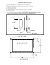
    1. Locate indicator in a convenient place on the vehicle. 2. Place the template in position and center punch in 4 places. 3. Drill holes as shown. 5. Cut out square hole. 6. Connect wiring to charger using butt connector supplied. 7. Install as shown. 8. Insert 4 #6-32 screws and tighten, (caution d...