- DL manuals
- Larson Davis
- Measuring Instruments
- 831
- User Manual
Larson Davis 831 User Manual
Summary of 831
Page 1
Model 831 sound level meter manual.
Page 2: Model 831 Manual
I831.01 rev o manual larson davis model 831 manual.
Page 3
Copyright copyright 2016, by pcb piezotronics, inc. This manual is copyrighted, with all rights reserved. The manual may not be copied in whole or in part for any use without prior written consent of pcb piezotronics, inc. Disclaimer the following paragraph does not apply in any state or country whe...
Page 4: Chapter 1
I831.01 rev o manual table of contents chapter 1 831 features 1-1 hardware features ................................................................................................ 1-1 basic measurements ............................................................................................. 1-...
Page 5: Chapter 6
View spectrum normalized ................................................................................5-30 any level display ............................................................................................... 5-41 chapter 6 run control 6-1 run control setup ..............................
Page 6: Chapter 12
I831.01 rev o manual locate record number ..................................................................................... 11-16 link to measurement history display .............................................................. 11-17 markers ........................................................
Page 7: Chapter 16
Chapter 16 sound recording 16-1 sound recording types ....................................................................................... 16-1 sound recording setup ....................................................................................... 16-2 manual sound recording ..................
Page 8: Chapter 21
I831.01 rev o manual chapter 21 lock/unlock the model 831 21-1 control panel - lock ........................................................................................... 21-1 fully locked ....................................................................................................... 21...
Page 9: Chapter 26
Chapter 26 upgrade firmware and options 26-1 slm utility-g3 ................................................................................................... 26-1 upgrading model 831 firmware ......................................................................... 26-2 upgrading options ............
Page 10: Hardware Features
Model 831 manual 831 features 1-1 c h a p t e r 1 831 features welcome to the larson davis model 831 . This versatile instrument, with graphic display, performs the functions of several instruments; it puts the combined features of a precision sound level meter and a real-time frequency analyzer in ...
Page 11: Basic Measurements
1-2 basic measurements model 831 manual • usb 2.0 full speed host connector for mass storage, cellular and dial-up modems and future devices • usb 2.0 full speed peripheral connector for control and data download by a pc • aux control connector for usb remote power, weather transducers and the 831-i...
Page 12: Available Options
Model 831 manual available options 1-3 • data files and data explorer • automatic data backup to prevent data loss on power failure • overall measurement • community noise measurement • voice annotation • gps data available options the model 831 is delivered with all firmware options available at th...
Page 13: No Charge Options
1-4 standard accessories model 831 manual no charge options the following options are available at no additional charge: • weather data: wind speed and direction, temperature, humidity (831-wthr) • analog modem or rs-232 communication (831-mdm) standard accessories some of these options may not be p...
Page 14: Optional Accessories
Model 831 manual optional accessories 1-5 • ws001 3 1/2” windscreen • 4 rechargeable aa nimh batteries other • lanyard optional accessories microphones • 1/2” free-field pre-polarized microphone, 50 mv/pa • 1/2” random incidence pre-polarized microphone, 50 mv/pa • 1/4” free-field pre-polarized micr...
Page 15
1-6 optional accessories model 831 manual • eps030-831 weather-proof enclosure for remote noise monitoring; includes battery • eps031 pole mount weather proof fiberglass enclosure for ac power and mounting to tro019- xx and trp020-xx series tripods; includes enclosure, internal brackets and 9-ah bac...
Page 16
Model 831 manual optional accessories 1-7 •bat012 100ah battery •bat013 2x21ah batteries weather data acquisition • 831-int 831 interface unit for use with 426a12 outdoor microphone preamplifier and weather sensors the sen028, sen029, and sen030 are no longer supported. • sen028 wind monitor; speed ...
Page 17
1-8 optional accessories model 831 manual cables direct input cable or adaptor • microphone extension cable: excxxx (shielded), where xxx is the length in feet (xxx = 010, 020, 050, 100 and 200 available) • cbl138 usb cable • cbl139 ac/dc output cable cables for environmental monitoring • cbl152 cab...
Page 18
Model 831 manual optional accessories 1-9 tripods • trp001 instrument/camera tripod with adp032 1/2 in. Microphone clip and used with eps2108-2 • trp002 microphone stand with boom • trp003 support tripod, heavy duty, can be used with eps029, eps030 and eps2106-2 • adp034 mounting adapter to attach e...
Page 19
1-10 optional accessories model 831 manual software • dna (data navigation and analysis) software provides setup and remote operation of the model 831, providing real-time data displays on a pc. Powerful graphics routines are provided to create custom data displays ranging from simple time histories...
Page 20: Unpacking and Inspection
Model 831 manual first use 2-1 c h a p t e r 2 first use this chapter outlines the steps to unpack the model 831 and prepare it for first use. The following topics are covered: • unpacking and inspection • connecting the microphone and preamplifier • installing 4 aa batteries • using usb power • pow...
Page 21
2-2 connecting the microphone and preamplifier model 831 manual engraved on the outside of the microphone as shown in figure 2-1 "microphone" . The preamplifier model and serial numbers are engraved on the outside surface of the preamplifier. You may be asked to provide this information during any f...
Page 22: Connecting The Preamplifier
Model 831 manual connecting the preamplifier 2-3 connecting the preamplifier caution: do not attempt to unscrew the collar/ring at the top of the model 831 body. The bottom end of the preamplifier has a 5 pin connector that fits snugly into the top of the model 831. Insert the preamplifier into the ...
Page 23: Powering The Model 831
2-4 disconnecting the preamplifier model 831 manual disconnecting the preamplifier on the front surface of the model 831, just below the preamplifier connector, is a small button. Press and hold this button while pulling the microphone / preamplifier assembly out of the model 831. Figure 2-4 push bu...
Page 24: Battery Power
Model 831 manual powering the model 831 2-5 battery power the model 831 is compatible with aa nickel metal hydride (nimh), alkaline or 1.5 volt lithium batteries. Energizer, duracell and other nationally recognized brands are the preferred suppliers of alkaline batteries. These will provide the user...
Page 25
2-6 powering the model 831 model 831 manual icon directly reflect the remaining estimated run time as displayed by the instrument. Low battery as the battery nears end-of-life (1% of capacity), the empty battery symbol will begin to flash. The unit will shut down in a short time because the battery ...
Page 26
Model 831 manual powering the model 831 2-7 insert 4 fresh aa batteries as shown in figure 2-8. Ensure correct alignment of the batteries + and - terminals as indicated by diagrams on the bottom of the battery compartment. Figure 2-8 insert batteries after the batteries are installed, insert the two...
Page 27: External Power Supply
2-8 powering the model 831 model 831 manual charge status led the charge status is indicated by an led beneath the power key as follows: • led continuously lit: charging • led not lit: not charging • led flashing at 1/sec: trickle charging. This is typically done early in the charging cycle when the...
Page 28: Power-Up Operation
Model 831 manual powering the model 831 2-9 low voltage shutdown the model 831 has a special feature to preserve the service life of an external sla (sealed lead-acid) battery by preventing it from being discharged excessively. When the battery voltage drops below the external shutoff voltage (defau...
Page 29
2-10 powering the model 831 model 831 manual insufficient external voltage if the external power source is operating the instrument, i.E. There is no usb or internal battery power available, and is less than about 10.8 volts, the display shown in figure 2- 10 appears with the grey box inside the bat...
Page 30: Power Control Page
Model 831 manual powering the model 831 2-11 power control page the estimated battery run time is only shown after running on batteries for more than one minute, which permits the battery voltage to stabilize. If the model 831 is on, pressing the 0 (on/off) key displays the power control screen. Fig...
Page 31: Hardware Power Switch
2-12 powering the model 831 model 831 manual hardware power switch do not use the hardware power switch to turn the model 831 off. This may cause data to be lost and permanent damage may occur. Press the 0 key for several seconds to turn off the meter. The hardware power switch on the bottom of the ...
Page 32: 831 Components
Model 831 manual overview 3-1 c h a p t e r 3 overview this chapter provides an overview of the components, displays, and functions of the 831 sound level meter. 831 components figure 3-1 the model 831 the standard model 831 shown in figure 3-1 includes the following: • 1/2 in. Diameter condenser mi...
Page 33: Hardware Power Switch
3-2 831 components model 831 manual • ac/dc output, control, usb, and external power connectors (shown in figure 3-2) • true “hand held” instrument with “sure grip” pads figure 3-2 shows the bottom view of the model 831. Figure 3-2 model 831 bottom view do not use the hardware power switch to turn t...
Page 34: Display
Model 831 manual 831 components 3-3 • i/o connector for peripherals and external power: typically used with external devices. For more information, see “i/o connector specification” on page a-9: •cbl143 and cbl151 cables: these cables permit the model 831 to be powered from external 12 v batteries •...
Page 35: Measurement
3-4 831 components model 831 manual comfortable viewing in most ambient light situations. Controls are provided for contrast and backlight adjustments. When the model 831 is first switched on, the live tab appears. When a measurement is in progress, a display similar to figure 3-3 is shown. Figure 3...
Page 36: Keypad
Model 831 manual 831 components 3-5 keypad the 831 meter has a 13 button keypad. This section describes the buttons on the keypad. Figure 3-4 shows the 831 keys. Figure 3-4 model 831 keys softkeys the three push button keys just beneath the display, on the body of the model 831, are called softkeys ...
Page 37
3-6 831 components model 831 manual figure 3-5 softkeys the function of each softkey is indicated by an icon or label on the bottom of the display. Softkeys are so named because the function of each key can change depending upon the screen, the context, or how it is programmed, as indicated by the l...
Page 38
Model 831 manual summary of displays and icons 3-7 summary of displays and icons tabs data is presented in tabbed format. Move between tabs by using the right and left softkeys. Page tabs are divided into pages that logically group the data together (i.E., 1/3 octave data on the live tab). Tabs may ...
Page 39
3-8 summary of displays and icons model 831 manual the external power connection icon appears when the model 831 is powered from an external power supply or via the usb port. Measurement name this is the file name to be used for the data file. Stability indicator presented in the form of an analog d...
Page 40
Model 831 manual summary of displays and icons 3-9 when using a microphone having a sensitivity of 50 mv/pa, the input overload will occur approximately as shown in table 3-4. Under range icon when the signal from the preamplifier drops to the point where the noise level of the instrument and the pr...
Page 41
3-10 summary of displays and icons model 831 manual when using a microphone having a sensitivity of 50 mv/pa, the input overload will occur approximately as shown in table 3-5. Oba under range icon when the signal from the preamplifier drops to the point where the noise level of the instrument and t...
Page 42
Model 831 manual summary of displays and icons 3-11 run pending icon the run pending icon appears when the 9 (run/ pause) key is pressed and the model 831 is waiting for filters and detector initialization to complete. The model 831 will automatically start the run after the wait or warm- up state i...
Page 43: Navigating and Selecting
3-12 navigating and selecting model 831 manual changing views in the data views, the labels of the left and right softkeys are left and right arrow symbols, respectively. These indicate that the left and right softkeys are used to scroll the selection of the tab being displayed in the corresponding ...
Page 44: Tab and Setting Displays
Model 831 manual tab and setting displays 3-13 pressing the 9 (run/ pause) key when the unit is in stop mode continues the previous run. The 7 key ends a run. Pressing the key a second time stores the data in a file. This key is only active on a data view screen. Tab and setting displays the 831 fea...
Page 45: Data Display Tabs
3-14 tab and setting displays model 831 manual control panel and return to the data display tabs, press the center softkey labeled close. Power control page the power control page is opened by pressing the 0 (on / off) key while on data view tabs. To exit from the power control page, press the cente...
Page 46: Measurement Settings Tabs
Model 831 manual tab and setting displays 3-15 data presented in the overall view would represent the measurement since t1 while the current view would represent the measurement since t2. With measurement history enabled, a series of separate measurements are made based on either manual key presses ...
Page 47
3-16 tab and setting displays model 831 manual • oba (optional): used to setup the real-time octave band frequency analysis • dosimeter 1 (optional): used to setup the parameters for the measurement of sound exposure and noise dose • dosimeter 2 (optional): used to setup the parameters for the measu...
Page 48
Model 831 manual tab and setting displays 3-17 control panel (tools) properties for a detailed description of the tools screen, see “control panel - system properties” on page 18-1. The control panel displays icons to represent the different functions available for the model 831. Pressing the 3 (too...
Page 49
3-18 tab and setting displays model 831 manual • device: enter instrument identification. • time: set date and time. • power: set controls affecting power consumption. • preferences: set a variety of system parameters such as autostore and usb storage. • localization: set the regional characteristic...
Page 50
Model 831 manual tab and setting displays 3-19 the communication tabs include the following: • status: display status of analog and wireless modems, rs-232 and usb channels. • modem: setup a dial-up modem • wireless: setup a wireless modem • rs-232: setup an rs-232 interface calibrate for a detailed...
Page 51: Parameter Selection
3-20 parameter selection model 831 manual figure 3-12 shows the about tabs sequence. Figure 3-12 softkey selection of about tabs the right and left softkeys are used to scroll between the about tabs. System utilities for a detailed description of the system utilities, see chapter 23 "system utilitie...
Page 52: Parameters In A Row
Model 831 manual parameter selection 3-21 parameters in a row these may appear as a single row or, when there are numerous parameters to define, as multiple rows as shown in figure 3-13. Figure 3-13 parameters with radio buttons use the 2 and 8 keys to highlight the parameter (frequency weighting, d...
Page 53: Drop Down List
3-22 parameter selection model 831 manual drop down list parameters of this type are associated with a parameter name followed by a data field indicating the present selection for that parameter. There may be a single parameter to be defined, or multiple parameters as shown in figure 3-14. Figure 3-...
Page 54
Model 831 manual parameter selection 3-23 entering alphanumeric strings it is easier to specify alphanumeric strings in slm utility-g3 or g4 software. In some instances you will be called upon to enter alphanumeric strings, such as creating a name or entering text information. Parameters of this typ...
Page 55: Entering Numeric Data
3-24 parameter selection model 831 manual repeated presses of the 8 key will produce the following sequence of characters: • capital letters a through z • lower case letters a through z • characters ! @ # $ * ( ) - + = [ ] . • numbers 0 through 9 • space repeated presses of the 2 key will produce th...
Page 56: Settings Screen
Model 831 manual basic measurement setup 4-1 c h a p t e r 4 basic measurement setup this chapter describes the setup of the model 831 to perform basic sound level measurements. These measurements may include the following: • leq, lmax, lmin corresponding to user-selected values of frequency weighti...
Page 57: Setup Tabs
4-2 setup tabs model 831 manual settings in use message if the model 831 is not connected to a computer running g4 ld utility software, ignore this section. If the g4 is connected to the model 831 when attempting to access the settings screen, the display shown in figure 4- 1 will appear. Figure 4-1...
Page 58: General Tab
Model 831 manual setup tabs 4-3 • control • triggers • day/night the right and left softkeys are used to scroll through the available tabs, to the right and left, respectively, in the order they are listed above. Each of these is described in detail in the sections which follow. General tab figure 4...
Page 59: Slm Tab
4-4 setup tabs model 831 manual slm tab the default values for these parameters are as shown in figure 4-4. Figure 4-4 slm tab selections of frequency weighting, detector, peak weighting and integration method are made one-at-a-time. Click to highlight the desired section prior to making the selecti...
Page 60
Model 831 manual setup tabs 4-5 integration method note that the model 831 can be set to run for a preset integration time as described in "manual stop, timed stop or stop when stable" on page 6-4 two integration methods are available: linear and exponential. Exponential integration exponential inte...
Page 61
4-6 setup tabs model 831 manual the effect on the a-weighted linearity range is shown in the section “f) linear operating range” on page b-9. Octave band analyzer tab (optional) the default values for these parameters are as shown in figure 4-5. This tab will only appear when the model 831 has the o...
Page 62: Ln Tab
Model 831 manual setup tabs 4-7 oba range setting in the low range, the full scale level is reduced by 33 db on the display. The default display ranges will be as follows: • normal range: 20 to 140 db • low range: -10 to 110 db however, the graph scaling range can be modified by the user as describe...
Page 63
4-8 setup tabs model 831 manual permit the calculation of ln values for any value of n in the range 00.01 to 99.99%. Selection of ln values the default values for these parameters are as shown in figure 4-7. The model 831 displays six ln values at a time, using user- selected values of n. These are ...
Page 64: Control Tab
Model 831 manual setup tabs 4-9 control tab figure 4-8 control tab a detailed description of the run mode is presented in chapter 6 "run control” on page 6-1. The control tab is used to set the run mode for the measurement to be performed. There are six modes of measurement duration available. In th...
Page 65
4-10 setup tabs model 831 manual figure 4-9 run mode parameter selections measurement history for a detailed description of measurement history, see chapter 12 "measurement history” on page 12-1. In figure 4-9, an item entitled enable measurement history appears for each run mode. Measurement histor...
Page 66: Triggers Tab
Model 831 manual setup tabs 4-11 delta the delta level is the maximum allowed change in current average level (i.E. L aeq ) permitted during the time interval defined below. The minimum level that can be set is 0 and the maximum is 5.0 db. The default is 0.2 db. Time the time is the minimum interval...
Page 67
4-12 setup tabs model 831 manual event might look as shown in figure 4-11 "exceedance event example" . Figure 4-11 exceedance event example for exceedance counters a noise event is initiated when the sound level rises above the event trigger level. A noise event ends when the sound level drops 2 db ...
Page 68: Day/night Tab
Model 831 manual setup tabs 4-13 basic exceedance event data note that hysteresis is only utilized to define the conclusion of a noise event for basic event counting as described in this section. It is not used in conjunction with the acquisition of noise event history data. The following exceedance...
Page 69
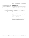
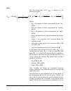
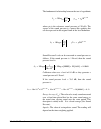
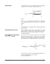
4-14 setup tabs model 831 manual l dn the default day-night level l dn is defined by the following formula: l den the default day-evening-night level l den is defined by the following formula: in the default form, the day has twelve hours, the evening has four hours and the night has eight hours, as...
Page 70: Exiting Settings Screen
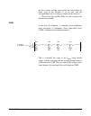
Model 831 manual exiting settings screen 4-15 and/or the night accordingly and also to choose the time for the start of the day. To accommodate these and other possible modifications, the day/night tab permits the user to modify the times for the beginning of the day, evening and night periods and t...
Page 71: Setup Manager
4-16 setup manager model 831 manual at this point the parameter changes made from the settings screen have not yet been implemented in the instrument. Select either yes or no , and press 5 to implement the changes or cancel the changes, respectively. This will return the data display screen to the d...
Page 72
Model 831 manual setup manager 4-17 press 5 to open the setup manager, shown in figure 4- 15. Figure 4-15 setup manager if no user-defined setups have been created and saved, the display will list two setups: • ld active: the setup presently active in the model 831 • ld default: the factory default ...
Page 73: Change to Ld Default Setup
4-18 setup manager model 831 manual note: setup names are limited to twelve characters. When user-defined setups have been added, the setup manager might look like figure 4-16. Figure 4-16 setup manager: user-defined setups added change to ld default setup if you wish to return all settings in the m...
Page 74
Model 831 manual setup manager 4-19 if you do not wish to save this measurement, select yes , which displays the message shown in figure 4-18. Figure 4-18 apply changes prompt select yes to return settings in the model 831 to the factory defaults. Otherwise, select no to cancel the settings change. ...
Page 75: Modifying The Active Setup
4-20 setup manager model 831 manual modifying the active setup when working with the setup manager, to modify the active setup, highlight the setup ld active and press the right software button labeled menu to bring up the display shown in figure 4-20. Figure 4-20 modify active setup menu highlight ...
Page 76: Save Modified Setup
Model 831 manual setup manager 4-21 note: if the present active setup has been derived from a user-defined setup, as described in “utilizing a user-defined setup” on page -19, applying changes will implement the same changes in the original user- defined setup file. Select yes to accept the changes,...
Page 77
4-22 setup manager model 831 manual overwrite an existing setup file if, rather than use a new name you wish to use the modified active setup file to replace an existing setup file, instead of pressing the yes box shown in figure 4-24, highlight the box labeled browse and press 5 . This will open a ...
Page 78
Model 831 manual setup manager 4-23 user-defined setup file operations a number of operations can be performed using the user- defined setup files by highlighting any one and pressing 5 to obtain the display shown in figure 4-27 user-defined file operations highlight the desired operation and press ...
Page 79: Close Setup Manager
4-24 setup manager model 831 manual delete delete permits the deletion of the selected file. A confirmation display will appear as shown in figure 4-29. Figure 4-29 delete setup file save as note that the name must contain no more than twelve characters and that a space cannot be used as a delimiter...
Page 80: Data Labels
Model 831 manual data display 5-1 c h a p t e r 5 data display in the previous chapter, the setup procedure for a basic sound level measurement was described. This chapter describes how this data would be displayed during or following a measurement sequence. The model 831 can measure many additional...
Page 81: Live Tab
5-2 live tab model 831 manual live tab the live tab may not appear as described here if the displays have been customized. For a detailed description of display customization, see the section "displays" on page 18-23 when the model 831 is turned on, the user is generally presented with the live tab....
Page 82
Model 831 manual live tab 5-3 weighting, and possibly the detector, will correspond to those selected in setup for the rms value. The 2nd numerical level display, l as in this example, corresponds to a user-selected parameter. The default value is l as . The selection of this value is described in "...
Page 83: Large Digit Sound Level
5-4 live tab model 831 manual large digit sound level the large digit display is provided to make it easier for the user to observe both the instantaneous sound level and along with the value of the user-selected spl1 trigger level. Figure 5-4 live tab, large digit in addition to displaying the curr...
Page 84
Model 831 manual live tab 5-5 1/1 octave band analyzer (optional) the 1/1 octave band analyzer display appears only when the instrument is loaded with the optional 831-ob3 firmware. Figure 5-5 live tab: 1/1 octave spectrum the 1/1 octave page shows a bar graph of sound level in 1/1 octave frequency ...
Page 85
5-6 live tab model 831 manual cursor use the 4 and 6 keys to move the cursor left and right, respectively. 1/3 octave band analyzer (optional) the 1/3 octave band analyzer display appears only when the instrument is loaded with the optional 831-ob3 firmware. Figure 5-6 live tab: 1/3 octave spectrum ...
Page 86: Triggering
Model 831 manual live tab 5-7 triggering for a detailed description of triggering, see "triggers tab" on page 4-11. Figure 5-7 live tab: triggering the triggering page displays the instantaneous sound level and instantaneous peak level with their associated trigger points. Exceedances of these trigg...
Page 87: Preamp Display
5-8 live tab model 831 manual preamp display the purpose of the preamp display is to validate proper operation of the system. It shows information regarding the preamplifier currently connected; specifically the preamplifier type, the spl and dc voltage at the input to the model 831 (for diagnostic ...
Page 88
Model 831 manual live tab 5-9 figure 5-9 426a12 preamp, e.A. On in figure 5-9 we see the display includes the serial number and the current internal temperature, humidity and dew point. The temperature, humidity and dew point metrics permit desiccant maintenance information to be gathered regularly ...
Page 89
5-10 live tab model 831 manual using icp preamplifier when using an icp power preamplifier, additional information can be displayed as shown in figure 5-10 figure 5-10 icp preamp displays here we can see how the dc voltage measured at the input of the model 831 is useful in diagnosing problems with ...
Page 90
Model 831 manual live tab 5-11 time, battery voltage and memory figure 5-11 live tab: time, battery, memory this page indicates the current date and time, the run time for the measurement, battery voltage, calculated run time and memory usage. Battery note that it takes approximately one minute to o...
Page 91: Overall Tab
5-12 overall tab model 831 manual overall tab the overall tab includes multiple pages. Use the 8 or 2 keys to navigate up or down through pages on the tabs. Note that from any of the displays described in this section, the user can also access the any level display, described in "any level display" ...
Page 92
Model 831 manual overall tab 5-13 the 2nd numerical value displayed is l apeak in this example, is a user-selected value. The selection of this value is described in “user-selected slm parameter” below. The time at the bottom of the page is the date and time the measurement was started. User-selecte...
Page 93
5-14 overall tab model 831 manual overall large digit sound level figure 5-14 overall tab: large digit display the graph scaling can be modified as described in section "adjust graph scale" on page 5-29. This page presents a data-compressed profile of the sound level for the run time of the measurem...
Page 94: Overall Slm
Model 831 manual overall tab 5-15 overall slm figure 5-15 overall tab: overall slm l as represents the live sound pressure level for the active frequency and time weightings and the l zpeak represents the live instantaneousness peak level. They are displayed here to allow the user to see these live ...
Page 95
5-16 overall tab model 831 manual 1/1 octave band analyzer (optional) the 1/1 octave band analyzer display appears only when the optional firmware 831-ob3 has been enabled and this measurement mode has been selected in the setup. Figure 5-16 overall tab: 1/1 octave spectrum note that the graph scali...
Page 96
Model 831 manual overall tab 5-17 lmax lmax is the maximum sound level of the highlighted frequency band. The maximum spectrum is determined by the max spec setting. Bin max when set to bin max , it is the maximum value which occurred during the entire measurement for that frequency band. Since indi...
Page 97: Ln Percentiles
5-18 overall tab model 831 manual note that the graph scaling can be modified as described in section "adjust graph scale" on page 5-29 and the display normalized to another spectrum, as described in section "view spectrum normalized" on page 5-30. The data displayed on this page is similar to that ...
Page 98: Nf30-101 Ln (Optional)
Model 831 manual overall tab 5-19 nf30-101 ln (optional) the nf30-101 ln display appears only when both the 1/3 octave oba bandwidth and nf30-101 firmware options have been enabled. The nf30-101 option computes the broadband ln table values from an energy sum of the 1/3 octave from 25 hz to 2 khz fi...
Page 99: Spectral Ln (Optional)
5-20 overall tab model 831 manual spectral ln (optional) the spectral ln display appears only when the optional 831-ob3 firmware has been enabled and the spectral ln mode set for 1/1 or 1/3 octave measurements, as described in "spectral ln mode" on page 4-7. Figure 5-20 overall tab: spectral ln the ...
Page 100: Exceedances
Model 831 manual overall tab 5-21 exceedances for a detailed description of noise events based on threshold exceedances, see "triggers tab" on page 4-11. Figure 5-21 overall tab: exceedances the exceedences page shows the number of exceedances that have occurred during the measurement and the total ...
Page 101: Overloads
5-22 overall tab model 831 manual overloads figure 5-22 overall tab: overloads the overloads page shows the number of times, the percent of time and the amount of time that the sound level meter and the oba have been overloaded. The community noise page is shown in figure 5-23. Figure 5-23 overall t...
Page 102: C-A And Impulsivity
Model 831 manual c-a and impulsivity 5-23 since community noise metrics are based upon full day measurements, they do not present valid data for measurements less than 24 hours duration. The community noise page displays the parameters l dn , l den, l ceq and l aeq , commonly used to evaluate commun...
Page 103: Industrial Hygiene
5-24 c-a and impulsivity model 831 manual the “c minus a” metric provides an indication of the low frequency content of noise measured by subtracting the a- weighted equivalent level from the c-weighted equivalent level. The integrated levels for l aeq are always calculated using the linear detector...
Page 104: Session Log Tab
Model 831 manual session log tab 5-25 • manually initiated recordings • marker initiated recordings • event recordings • measurement recordings session log tab figure 5-26 session log tab the session log is a record of data accumulation actions. Resetting and storing data will clear the session reco...
Page 105
5-26 session log tab model 831 manual • out of memory • preamplifier disconnect the measurement status icons are described in "measurement status" on page 3-10. The icons in the left column of the display indicate the action: run, pause, voice recording, etc. The date and time of the action is displ...
Page 106
Model 831 manual session log tab 5-27 figure 5-28 presents a list of all actions and the valid causes for each of them. Figure 5-28 session log actions and causes voice message/sound recording playback note that voice messages, which are recorded using the voice recorder page of the control panel, c...
Page 107
5-28 session log tab model 831 manual message or sound recording will appear as shown in figure 5-29. Figure 5-29 highlighted voice message, session log to play back the highlighted voice message, press 5 or select the play menu item, shown in figure 5-30. Figure 5-30 voice recording play menu.
Page 108: Adjust Graph Scale
Model 831 manual adjust graph scale 5-29 adjust graph scale the default amplitude (db) settings for the graphic display of sound pressure level versus time and frequency spectra (1/1 and 1/3 octave) are as indicated below: • level vs time graph: 20 db to 140 db • frequency spectra, normal range: 20 ...
Page 109: View Spectrum Normalized
5-30 view spectrum normalized model 831 manual view spectrum normalized note that the live spectrum will continue to change in time following the normalization, whereas the reference spectrum will remain the same. The default 1/1 and 1/3 octave spectrum displays present the amplitude versus frequenc...
Page 110
Model 831 manual view spectrum normalized 5-31 highlight view normalized and press 5 to make the selection. This will display the spectrum in the normalized view, as shown in figure 5-35. Figure 5-35 normalized live spectrum display: no reference selected since a reference spectrum has not yet been ...
Page 111
5-32 view spectrum normalized model 831 manual the items listed in this menu are as follows: • 1 • 2 • 3 • 4 • a • c • -a • -c the first four items permit the user to define four reference spectra based on the spectrum being displayed. Since the live spectrum only displays spl, there is little need ...
Page 112
Model 831 manual view spectrum normalized 5-33 normalized using the measured spectrum when the displayed spectrum has been normalized using the measured spectrum, and the sound being measured is not much different than it was previously, the display will resemble figure 5-37. Figure 5-37 normalized ...
Page 113
5-34 view spectrum normalized model 831 manual adjusting graph display because some of the frequency components in the normalized view may be small or negative, the adjust graph function described in "adjust graph scale" on page 5-29 can be used to obtain a graph having both positive and negative am...
Page 114
Model 831 manual view spectrum normalized 5-35 note that the scale in figure 5-39 was adjusted as described in "adjusting graph display" on page 5-34 in order to display the low level and negative amplitudes. Normalizing using user-defined spectrum the user can also define their own reference spectr...
Page 115
5-36 view spectrum normalized model 831 manual 6 , 8 and 2 keys to input a numerical value and press 5 to complete the process. In this example the cursor is on the 1 khz frequency band, so if the amplitude were entered to be 50 db, the result would be as shown in figure 5-42 figure 5-42 example use...
Page 116: Overall Display
Model 831 manual view spectrum normalized 5-37 overall display in general, obtaining a normalized display of 1/1 and 1/3 octave spectra appearing on the overall tab is the same as for live displays, described in "live display" on page 5-30. The major difference is that spectra appearing on the overa...
Page 117
5-38 view spectrum normalized model 831 manual figure 5-45 spectrum type menu using this menu, the user can select from the three spectrum types; leq, lmax and lmin. Highlight the desired parameter and press 5 to make a selection. If no reference spectrum has yet been defined, the displayed spectrum...
Page 118
Model 831 manual view spectrum normalized 5-39 figure 5-47 lmax - lmin spectrum if the model 831 were still running, the lmax would continue changing but the reference spectrum, based on the lmin spectrum measured previously, would remain the same..
Page 119
5-40 view spectrum normalized model 831 manual normalizing using frequency weighting when using frequency weighting for normalization, the display will be similar to that for live spectra, described in "normalizing using frequency weighting" on page 5-34, except that the use will have the option of ...
Page 120: Any Level Display
Model 831 manual any level display 5-41 normalizing using user-defined spectrum the creation and use of user-defined reference spectra for the overall display are the same as for the live display, described in the section "normalizing using user-defined spectrum" on page 5-35. Graph relative when th...
Page 121: Live Screen
5-42 any level display model 831 manual the any level display can also be accessed from the current and measurement display tabs, which are used to display measurement history data; see chapter 12 "measurement history” on page 12- 1. To obtain the any level display from either the live or overall sc...
Page 122: Overall Screen
Model 831 manual any level display 5-43 close display note that the instrument keypad is not operational when the any level display is being displayed. As a result, the run state cannot be changed until that display has been closed. To close the any level display, press the close softkey. Overall sc...
Page 123
5-44 any level display model 831 manual.
Page 124: Run Control Setup
Model 831 manual run control 6-1 c h a p t e r 6 run control the model 831 provides a number of run modes to control the time duration of a measurement. The most simple are manual stop, timed stop and stop when stable. More advanced are the continuous, single block time and daily timer modes. When c...
Page 125
6-2 run control setup model 831 manual there are six modes of measurement duration available. • manual stop • timed stop • stop when stable • continuous • single block time • daily time a brief description of each is presented in the following sections. Manual stop the stop key will stop a measureme...
Page 126
Model 831 manual run mode with measurement history 6-3 the ability to restart when power is restored following a power failure, with documentation in the session log, is a valuable feature for long- term remote noise monitoring applications if the unit stops due to a power failure, the session log i...
Page 127
6-4 run modes without measurement history model 831 manual run modes without measurement history all of the six run modes have a check box to enable the measurement history feature, as is shown in the figures appearing in the sections which follow. The setup descriptions presented in the following s...
Page 128
Model 831 manual run modes without measurement history 6-5 timed stop the time at which the measurement is to stop is entered manually into the time data field. In the timed stop mode, the minimum time of one second (00:00:01) will be saved if the time setting is left as 00:00:00 when closing or exi...
Page 129: Continuous
6-6 run modes without measurement history model 831 manual continuous figure 6-3 setup of continuous run mode when using the continuous run mode, the measurement is initiated manually by pressing the 9 key and is manually stopped by pressing the 7 key. With the enable measurement history option sele...
Page 130
Model 831 manual run modes without measurement history 6-7 daily auto-store when daily auto-store is set to “never”, as shown in figure 6-3, the continuous run mode is essentially the same as the manual run mode, with the exception that in continuous it automatically begins running, thus measuring c...
Page 131
6-8 run modes without measurement history model 831 manual you can program an automatic once per day calibration check of the system. During calibration the ldn is paused. The net result has no effect on the history data while the calibration tone is on. Highlight the cal-check field and press the 5...
Page 132
Model 831 manual run modes without measurement history 6-9 the selection and setting of appropriate parameters for the continuous, single block time and daily timer run modes is shown in figure 6-7. Figure 6-7 setup of single block timer and daily timer run modes measurements are initiated for one o...
Page 133
6-10 run modes without measurement history model 831 manual example as an example, suppose we have begun a daily timer setup as shown in figure 6-8. Figure 6-8 daily time setup example the selected blocks should not overlap. For example, if the end time 1 is set to 00:00:04, then the start time 2 sh...
Page 134
Model 831 manual run modes without measurement history 6-11 with the enable measurement history option selected in these modes, a time setting left as 00:00 (no time) will be saved as 00:01 (one minute) upon closing or leaving the control tab..
Page 135
6-12 run modes without measurement history model 831 manual.
Page 136: Configuration of The System
Model 831 manual making a measurement 7-1 c h a p t e r 7 making a measurement in this chapter we describe how to make and store an accurate sound level measurement. Before doing this, make sure that the model 831 has been setup to meet the requirements for the measurement as described in chapter 4 ...
Page 137: Start-Up Period
7-2 switching on the model 831 model 831 manual start-up period with standard memory, the start-up period will be less than two minutes. With the optional 2 gb memory, the startup period can be several minutes for the first boot-up. As the instrument is starting up, the display will show the followi...
Page 138: Model 831 Setup
Model 831 manual model 831 setup 7-3 data view and data display screen refer to live, overall and session log tabs. When the model 831 is fully started, the data display screen will appear as shown in figure 7-2. Figure 7-2 data display screen the 7 (stop/store) key will produce a steady red light t...
Page 139: Microphone Extension Cable
7-4 positioning the model 831 model 831 manual the body of the operator interfering with the measurement, the meter should be located as far as possible from the body. Thus, when actually performing the measurement, the operator should place himself at a distance behind the tripod-mounted meter, or ...
Page 140: Performing The Measurement
Model 831 manual performing the measurement 7-5 figure 7-4 placement of windscreen prior to beginning the measurement, select the live view. You can now see a live display of the instantaneously measured data. The position of the vertical scroll bar on the right side of the display indicates the pag...
Page 141: Measurement State
7-6 performing the measurement model 831 manual • 7 key led is red when performing a measurement, the state of the model 831 is indicated by the illumination of these two keys indicated in table 7-7-1. 1 the state of waiting for valid data will occur when the instrument is first switched on, and als...
Page 142: Data Display
Model 831 manual performing the measurement 7-7 data display see “overall tab” on page 5-12. The measured data are available for display from the overall view. These data are distributed over thirteen sections (with the 831-ih and 831-ob3 options). Use the 8 and 2 keys to change sections. The first ...
Page 143: Measurement Range
7-8 performing the measurement model 831 manual figure 7-6 multiple sound level parameters measurement range the measurement ranges over which the model 831 meets the standards, which depend upon the selected frequency weighting, as shown in “performance specifications” on page a-4. Measurements whi...
Page 144: Pausing The Measurement
Model 831 manual performing the measurement 7-9 while the overload is present, the icon will flash on and off. If an overload occurs while running the overload icon will latch on and will not be removed from the display. A reset will clear the icon. Under range indication when the signal from the pr...
Page 145: Back Erase
7-10 performing the measurement model 831 manual back erase the back erase function permits the user to rapidly delete from the measurement the effects of acoustical events that have occurred during the previous five or ten seconds. Back erase disabled the back erase feature is unavailable when any ...
Page 146
Model 831 manual performing the measurement 7-11 the back-5s label does not appear until the measurement duration is of least 5 seconds or more since the last stop or pause. Press the center softkey to implement the five second back erase. The center softkey then shows an undo option (unless it has ...
Page 147
7-12 performing the measurement model 831 manual > ten seconds since last stop or pause after pressing the center softkey to implement a five second back erase, if the measurement duration since the last stop or pause has been more then ten seconds, the center softkey will then be labeled back-10s ,...
Page 148: Resetting The Measurement
Model 831 manual performing the measurement 7-13 modified profile graph after a back erase operation has been performed, the sound level profile graph will be modified to indicate the erase operation as shown in figure 7-11. Figure 7-11 modified profile graph time history records the time history re...
Page 149: Stopping The Measurement
7-14 performing the measurement model 831 manual the ok response will already be highlighted, so simply press the 5 (enter) key to continue. Otherwise, highlight cancel and then the 5 to cancel both the stop and the reset operations. After selecting to stop the measurement, the save file menu, shown...
Page 150: Storing The Measurement
Model 831 manual storing the measurement 7-15 storing the measurement a measurement can only be stored when the measurement has been stopped. To store the measurement, press the 7 key one more time while stopped. The save file menu will then be displayed, as shown in figure 7-13. Figure 7-13 save fi...
Page 151: Low Level Sound Fields
7-16 storing the measurement model 831 manual highlight the file which is to be overwritten and press 5 . This will replace the file name and number which previously appeared with this one, as shown in figure 7-15. Figure 7-15 overwriting a saved file to continue with the overwrite operation, highli...
Page 152
Model 831 manual storing the measurement 7-17 lcorr = corrected sound level lmeas = measured sound level linh = inherent noise level.
Page 153: Case 1
7-18 recovery after improper shutdown model 831 manual recovery after improper shutdown note: there is a risk of file-system corruption when power to the system is unexpectedly shut off. To minimize this risk, always follow proper shut- down procedures. When the model 831 has been shutdown improperl...
Page 154
Model 831 manual recovery after improper shutdown 7-19 •if the user responds by selecting not to store the data, the sequence moves to step 2. Step 2 the user is prompted to reset the instrument • if the user responds by selecting to reset the instrument, the instrument is reset. • if there is no us...
Page 155
7-20 recovery after improper shutdown model 831 manual.
Page 156: Calibration Overview
Model 831 manual calibration 8-1 c h a p t e r 8 calibration this chapter describes both the purposes and steps for calibrating the model 831. Calibration overview sensitivity determination the primary role of sound level meter calibration is to establish a numerical relationship between the sound l...
Page 157: Control Panel - Calibrate
8-2 control panel - calibrate model 831 manual appear to warn the user when the difference between these two values exceed 3 db. Control panel - calibrate to activate the calibration function, press the 3 (tools) key and highlight the calibrate icon as shown below. Figure 8-1 control panel press the...
Page 158
Model 831 manual control panel - calibrate 8-3 figure 8-2 calibration tabs calibrate tab history tab sensitivity tab certification tab e.A. Check tab e.A. History tab calibration spectrum e.A. Check spectrum tab.
Page 159
8-4 control panel - calibrate model 831 manual calibrate tab the calibrate tab is used when performing an acoustic calibration, including the selection of the sound level calibrator to be used and the implementation of the calibration procedure. History tab the history tab lists the results, along w...
Page 160: Acoustic Calibration
Model 831 manual acoustic calibration 8-5 acoustic calibration when using a 426a12 outdoor microphone and power supply or a model 2100 outdoor preamplifier, a calibration check can be performed remotely using an electrostatic actuator (e.A.) as described in "e.A. Check" on page 8-18. This is the mos...
Page 161
8-6 acoustic calibration model 831 manual model 831 with 1/2” free-field microphone the cal200 provides a nominal pressure level of 94 db or 114 db. The exact levels are printed on the larson davis calibration sheet that came with the calibrator. When using a free-field microphone, the pressure leve...
Page 162: Parameter
Model 831 manual acoustic calibration 8-7 environmental parameter ranges for proper calibration of a class 1 sound level meter such as the model 831, the calibration procedure and the correction values apply over the ranges presented in table 8-1. Set the cal200 level switch to 114 db. Adding a cali...
Page 163: Microphone Selection
8-8 acoustic calibration model 831 manual figure 8-3 new calibrator if the desired calibrator is already in the list, select the calibrator and press 5 . The calibration information will appear above. Microphone selection select the microphone to be used from the sensitivity tab, as shown in figure ...
Page 164: Performing The Calibration
Model 831 manual acoustic calibration 8-9 larson davis microphone the left side of the type field is a text box, where manual text entries can be entered when it is selected (as shown in figure 8-4). In the type field, highlight the down arrow and press 5 . If using one of the larson davis microphon...
Page 165
8-10 acoustic calibration model 831 manual highlight the calibrate button on the model 831 and press 5 , opening the calibrating display shown in figure 8-6. Figure 8-6 calibrating the present sound level (94.56 db), the difference between the calibration level and the present sound level ( and an i...
Page 166
Model 831 manual acoustic calibration 8-11 outside range of normal sensitivity when the results of the calibration correspond to a sensitivity greater than 3 db outside the range of the nominal sensitivity for that microphone, the message shown in figure 8-8 appears. Figure 8-8 outside normal sensit...
Page 167: Calibration History
8-12 acoustic calibration model 831 manual calibration history the results of the last ten calibrations are displayed on the history tab, shown in figure 8-10. Figure 8-10 calibration history tab here we see the date and time of each calibration, along with the sensitivity in db re. 1 v/pa and the d...
Page 168: Sensitivity Tab
Model 831 manual sensitivity tab 8-13 calibration spectrum the 831-ob3 option and 1/3 octave setting are automatically enabled (whether purchased or not) for acoustic calibrations and calibration checks so that spectra can be stored in history records and data files. Press 5 to display the spectrum ...
Page 169: Noise Floor
8-14 sensitivity tab model 831 manual figure 8-12 sensitivity tab noise floor the noise floor is calculated as the energy sum of the microphone self noise, preamplifier self noise and instrument self noise. The appropriate noise floor, as well as the nominal sensitivity, is computed automatically in...
Page 170
Model 831 manual calibration without preamplifier 8-15 calibration without preamplifier there may be situations where the microphone preamplifier provided with the model 831 is not being used. For example when a hydrophone is being used, no level calibrator is available so the sensitivity must be in...
Page 171: Certification
8-16 certification model 831 manual certification figure 8-14 certification tab a certification interval of one year is recommended but this can be lengthened or disabled depending on applicable requirements. The user has the opportunity to set the calibration interval and a calibration reminder. Ce...
Page 172
Model 831 manual certification 8-17 available values of certification interval are as follows: • 1 year • 2 years • 3 years • 4 years • never the default value is never available values of certification reminder are as follows: • 15 days • 30 days • 45 days • 60 days • never the default value is nev...
Page 173: E.A. Check
8-18 e.A. Check model 831 manual e.A. Check when using a larson davis model 426a12 outdoor preamplifier and power supply or model 2100 outdoor preamplifier, this menu is used to perform a remote calibration check by switching on the electrostatic actuator (e.A.) contained within rain hat of the mode...
Page 174
Model 831 manual e.A. Check 8-19 check and press 5 to initiate a calibration. Which will produce the display shown in figure 8-19. Figure 8-19 calibrating in progress display this display will indicate the difference between the present level and the previously measured level. When the measurement i...
Page 175: E.A. History
8-20 e.A. History model 831 manual no had been selected for the save as standard e.A. Level inquiry it will be saved. Background noise if the measured level during calibration is not stable, the model 831 will assume that there is contamination due to background noise and abort the calibration. Also...
Page 176: Measurement Setup
Model 831 manual industrial hygiene 9-1 c h a p t e r 9 industrial hygiene this chapter describes the measurement features associated with the industrial hygiene optional firmware 831-ih. Measurement setup the industrial hygiene measurement features are setup from the settings screen, in the same ma...
Page 177: Predefined Setups
9-2 measurement setup model 831 manual predefined setups in most cases, measurements of this type are setup to conform to a specific standard. The model 831 permits the user to create such a setup in a single step by simply selecting the applicable standard. The standards addressed by the model 831 ...
Page 178
Model 831 manual measurement setup 9-3 all parameters will be set according to the setup selected, as shown in figure 9-3. Figure 9-3 iec setup parameters individually defined on the dosimeter tabs, there are two fields (name and exchange rate) and two sections (threshold and criterion). Name field ...
Page 179
9-4 measurement setup model 831 manual the value desired. Highlight the desired section and proceed as described below. Exchange rate to set the exchange rate, highlight the data field and press 5 to open a drop down list of values, as shown in figure 9-4 "exchange rate list" . Figure 9-4 exchange r...
Page 180: Data Display
Model 831 manual data display 9-5 data display the industrial hygiene measurement data are displayed on the overall tab of the data display view, as are the results of the basic sound level measurements as described in chapter 5 “data display” on page 5-1. Four sections will appear: sound exposure ,...
Page 181: Dosimeter 1 and 2
9-6 data display model 831 manual dosimeter 1 and 2 figure 9-6 dosimeter 1 display in this example, we can see that the measurement parameters correspond to the setup named “osha-1”. Twa(8.0) the value of twa(8.0) (time weighted average for 8 hours) is based on data measured during the run time and ...
Page 182
Model 831 manual data display 9-7 time and calculated without regard to the criterion time. Continuing with the example in the above paragraph, the projtwa for that ten minute measurement represents the value of twa which would be measured if the noise measured during the ten minute period had conti...
Page 183: Sea
9-8 data display model 831 manual sea the sea parameter is used primarily in the canadian province of quebec. Figure 9-7 sea display sea is an integration of 1 second peaks that exceeded 120 db. Both the sea value and the frequency weighting used for the measurement are displayed..
Page 184
Model 831 manual voice recording 10-1 c h a p t e r 10 voice recording control panel - voice recording voice recordings are recorded using a sample rate of 8 khz. To activate the voice recorder page, press the 3 (tools) key and highlight the voice recorder icon as shown below. Figure 10-1 control pa...
Page 185: Voice Recorder
10-2 voice recorder model 831 manual without headset with no headset plugged in, a record may be made of the sound arriving at the measurement microphone. Voice recorder figure 10-2 voice recorder page the 5 key can also be used to play the highlighted voice record. The voice recorder page will pres...
Page 186: Playback
Model 831 manual voice recorder 10-3 the microphone level can be adjusted with the three position microphone switch found on the headset (acc003). The recording message box will appear. The meter indicates the relative signal level from the recording microphone and the progress bar shows the elapsed...
Page 187
10-4 voice recorder model 831 manual use the volume control on the headset (acc003) to adjust the playback level. With a headset attached to the headset jack on the bottom of the case, you will hear the voice recording in the headset speaker. Figure 10-5 playback the meter indicates the relative amp...
Page 188: Metrics Logged
Model 831 manual time history 11-1 c h a p t e r 11 time history this chapter describes the measurement features associated with the optional data logging firmware 831- log and 831-fst. Metrics logged using the time history mode, the model 831 can automatically log a large number of metrics, or para...
Page 189: Acoustical Metrics
11-2 metrics logged model 831 manual acoustical metrics time interval values these are integrated (l eq ), maximum (l peak , l smax , l fmax , l imax ) and minimum (l smin , l fmin , l imin ) values evaluated for the time interval since the preceding sample. Separate values are determined for a, c a...
Page 190: Non-Acoustical Metrics
Model 831 manual metrics logged 11-3 measured and saved with millisecond resolution. This is described in more detail in the section "select time history metrics" on page 11-6. 1/1 and 1/3 octave spectra the optional firmware 831-ob3 is required for these metrics to be measured. When 1/1 and/or 1/3 ...
Page 191: Time History Setup
11-4 time history setup model 831 manual wind gust speed wind gust direction temperature: average, max and min levels humidity: average, max and min levels time history setup setup time history on the time history tab on the measurement setup view, as shown in.Figure 11-1 figure 11-1 time history se...
Page 192: Set Time History Period
Model 831 manual time history setup 11-5 menu, as shown in figure 11-2. Note that the default values for these parameters are as shown in figure 11-2. Figure 11-2 time history setup menu: enabled set time history period to set the time history period, use the 2 key to highlight the period data field...
Page 193: Select Time History Metrics
11-6 time history setup model 831 manual note that the values 2.5 ms, 5 ms and 10 ms will only appear when the optional firmware 831-fst has been enabled. As you scroll downwards, when the highlight reaches the bottom of the window, the list will scroll upwards to reveal additional values. Milliseco...
Page 194
Model 831 manual time history setup 11-7 time history increment > 10 ms when the time increment selected is > 10 ms, the list of available metrics will appear as shown in figure 11-4, with the first item in the options list highlighted. Figure 11-4 time history options window: time increment > 10 ms...
Page 195
11-8 time history setup model 831 manual time history increment 10 ms when the selected time increment is 10 ms, the time history options window will appear as shown in figure 11-5 . Figure 11-5 time history options window: time increment 10 ms when using such short time increments, the only paramet...
Page 196: Time History Display
Model 831 manual time history display 11-9 time history display single value metrics when the model 831 is not equipped with the optional firmware 831-ob3, or if it is equipped with this option but the measurement of 1/1 and 1/3 octave spectra has been set to off in the measurement setup, all measur...
Page 197
11-10 time history display model 831 manual data display at cursor position holding down the left or right arrow keys will move the cursor faster as the key is held down longer. Holding the key accelerates movement through the time history. The 6 and 4 keys are used to move the cursor right or left,...
Page 198
Model 831 manual time history display 11-11 at any time, the role of the left and right arrow keys, as well as the means to change it, are indicated in the lower portion of the display, as shown in figure 11-8. Figure 11-8 role of left/right arrow keys: time history display locate record number to j...
Page 199: Frequency Spectra
11-12 time history display model 831 manual appeared in the list when selected, as described in "select time history metrics” on page 11-6. By pressing the 6 and 4 keys, the value displayed can be shifted to represent a metric one later or earlier, respectively, in sequence in the user-created list ...
Page 200
Model 831 manual time history display 11-13 except for the bandwidth, these displays are identical, so we will use a 1/1octave spectrum as an example. Figure 11-10 time history display: spectra metrics, section 2 and 3 left/right arrow keys for the display shown in figure 11-10, the 4 and 6 keys hav...
Page 201: Frequency Band Time History
11-14 time history display model 831 manual figure 11-11 role of left/right arrow keys: frequency spectra display frequency band time history from the frequency spectra display, press the 2 key to obtain the frequency band time history display shown in figure 11-12 figure 11-12 frequency band time h...
Page 202
Model 831 manual time history display 11-15 in this display, the time history of the lzeq level is shown at 1.00 khz, the frequency of the cursor position used in frequency spectrum display shown in figure 11-10 when changing to this display. Use the 4 and 6 keys to change the record number (time va...
Page 203: Locate Record Number
11-16 locate record number model 831 manual locate record number to rapidly change the record number, rather than use the cursor to step through the range of records, press the menu softkey which will produce the display shown in figure 11-17. Figure 11-14 locate record number highlight locate and p...
Page 204
Model 831 manual link to measurement history display 11-17 locate a specific record to locate a specific record, highlight the record number field and press 5 to add a cursor to the record number field, as shown in figure 11-16. Figure 11-16 record number cursor enter the desired record number using...
Page 205: Markers
11-18 markers model 831 manual markers markers are used to annotate portions of the time history, especially for the purpose of identifying sound sources as they become dominant in the measurement. The model 831 offers ten separate user-definable markers. Markers setup note that the default values f...
Page 206
Model 831 manual markers 11-19 figure 11-19 markers setup 6-10 naming a marker the process of naming markers is simplified by using the 831 utility software. Highlight the field of the marker to be named and press 5 . This will produce a cursor which can be moved left and right to different digit po...
Page 207: Using Markers
11-20 markers model 831 manual using markers the time history tab of the data display view is used to display the data, as shown in figure 11-6 “time history display: first point; keypress" . After the measurement is begun, press the menu key to bring up the display shown in figure 11-21. Figure 11-...
Page 208
Model 831 manual markers 11-21 setting all markers off to set all markers to off , press the right softkey labeled none . Close marker control window press the center softkey labeled close to close the marker control window and return the display to the standard time history display. Markers on time...
Page 209
11-22 markers model 831 manual.
Page 210
Model 831 manual measurement history 12-1 c h a p t e r 12 measurement history measurement history is used to perform a sequence of measurements using the same setup, either manually or automatically, which provide the same data as is obtained from the basic measurement, described in chapter 5 "data...
Page 211: Continuous and Timer Modes
12-2 continuous and timer modes model 831 manual continuous and timer modes for these run modes, when the measurement history is enabled, a series of measurements will be performed and stored automatically, each running for a user-defined time interval. At the time the check mark is placed in the me...
Page 212: Timed Stop Mode
Model 831 manual timed stop mode 12-3 valid measurement times when other values are selected, the interval time sync will still function, but the time for which the first measurement is cut short will be different. See "other measurement times" below for further detail. The interval time sync functi...
Page 213
12-4 timed stop mode model 831 manual measurement counter when the time is set to one minute or more for the time stop mode, the measurement counter field will appear as shown in figure 12-4. Figure 12-4 measurement counter measurement counter is used to set the number of measurements to be made dur...
Page 214
Model 831 manual manual and stop when stable modes 12-5 manual and stop when stable modes for these run modes, the measurement history does not automate the measurement and storage of data as it does for the continuous, single block timer and daily timer modes. However, it does simplify the number o...
Page 215: Current Tab
12-6 display of measurement history data model 831 manual current tab when the first measurement is in progress, the data will appear on the current tab, the first section of which is shown in figure 12-5. . Figure 12-5 time history display: current tab when that measurement is complete, its data wi...
Page 216: Measurement Tab
Model 831 manual display of measurement history data 12-7 measurement tab the measurement tab can display data for any one of the previously completed measurements. These measurement records are numbered in sequence from the first to the last. The data displayed in the first section of the measureme...
Page 217: Section
12-8 display of measurement history data model 831 manual 3 records profile display with leq, l smax and l smin row 1 column 3 see figure 12-8 for detailed view 4 max, min and peak levels row 1 column 4 5 1/1 octave spectrum row 1 column 4 option 831-ob3 required 6 1/3 octave spectrum row 2 column 1...
Page 218
Model 831 manual display of measurement history data 12-9 figure 12-7 measurement history displays.
Page 219
12-10 display of measurement history data model 831 manual record profile display there is no cursor on this graph nor a numerical display of amplitude or time. The third section on the measurement tab presents a profile (level versus time) for the selected measurement record, as shown in figure 12-...
Page 220: Link to Time History
Model 831 manual storing a measurement history 12-11 non-specta displays with the exception of frequency spectra displays, the 6 and 4 keys are used to step the selected measurement record number up or down, respectively. Frequency spectra displays when a frequency spectrum is displayed, the 6 and 4...
Page 221
12-12 link to time history model 831 manual figure 12-11 time history display.
Page 222: Level Based Events
Model 831 manual event history 13-1 c h a p t e r 13 event history the optional firmware module 831-ela is required in order to measure and store the metrics associated with exceedance events. Level based events read “triggers tab” on page 4-11 prior to working with the event history module. Event h...
Page 223: Event History Setup
13-2 event history setup model 831 manual event history setup the event history is setup on the event history tab in the measurement settings screen. If this is not already enabled, there will be nothing except an unchecked event history check box. The default values for these parameters are shown i...
Page 224: Trigger Method
Model 831 manual trigger method 13-3 peak levels drop below their threshold values. However, there may be situations where the sound level drops below the threshold for a short period of time before rising above it again, in which case the user may prefer to consider this a continuation of the event...
Page 225: Level Trigger Method
13-4 trigger method model 831 manual level trigger method in the section “triggers tab” on page 4-11, it is explained how the triggers menu, shown in figure 13-2, is used to set the parameters defining exceedance events. Figure 13-2 triggers menu an exceedance event for which event history data is m...
Page 226: Dynamic Trigger Method
Model 831 manual trigger method 13-5 to select the level trigger method, highlight the trigger method field and press 5 to open the trigger method menu, shown infigure 13-3. Figure 13-3 trigger method menu highlight level and press 5 to implement the selection. Dynamic trigger method dynamic trigger...
Page 227
13-6 trigger method model 831 manual figure 13-4 fixed level trigger; lower level events missed dynamic trigger using the dynamic trigger method, you can select to track the l 90 level (background noise) and trigger a noise event when the measured level exceeds the l 90 level plus an offset, which i...
Page 228
Model 831 manual trigger method 13-7 figure 13-5 dynamic trigger: lower level events captured during low background noise periods to select the dynamic trigger method, highlight the trigger method field and press 5 to open the trigger method menu, shown in figure 13-6 figure 13-6 trigger method menu...
Page 229
13-8 trigger method model 831 manual dynamic trigger parameters after selecting the dynamic trigger method, it is necessary to return to the triggers tab, shown in figure 13-7, by pressing the left softkey figure 13-7 triggers menu: dynamic triggering the triggers tab now includes the dynamic trigge...
Page 230
Model 831 manual trigger method 13-9 options available, having the characteristics presented in table 13-1. To set the dynamic response, highlight the dynamic response data field and press 5 . Set the digit to a value between 1 and 5 and press 5 . Dynamic trigger example suppose the dynamic trigger ...
Page 231: Event Time History Setup
13-10 event time history setup model 831 manual event time history setup when event time history has been enabled, time history data will be measured as a part of each event history. Note that the default values for these parameters are as shown in figure 13-8. Highlight the event time history check...
Page 232: Spectral Mode
Model 831 manual event time history setup 13-11 milliseconds 20, 50, 100, 200, 500 seconds 1, 2, 5, 10 highlight the desired period value and press 5 to make a selection. Spectral mode a spectral time history can be measured for each event by setting spectral mode to on . The bandwidth of the spectr...
Page 233: Maximum Number of Samples
13-12 event history display model 831 manual post-trigger to set the number of post-trigger samples, highlight the post-trigger data field and press 5 . Enter the desired value and press 5 . Maximum number of samples to limit the amount of memory used by event time histories, the user can specify th...
Page 234: Trigger Status Icons
Model 831 manual event history display 13-13 trigger status icons the model 831 begins sampling data as soon as the 9 (run/pause) key is pressed. The trigger status is indicated by one of five trigger status icons as described below. Pre-trigger pre-trigger is being collected but there are fewer sam...
Page 235: Sound Recording In Progress
13-14 event history display model 831 manual continuation when the level no longer exceeds the trigger level we enter the con? State where we wait for the continuation time in preparation to end the event. We continue processing event data and transition back to the valid state if the level exceeds ...
Page 236: Levels Display
Model 831 manual event history display 13-15 levels display the second section is the levels display, which is shown in figure 13-13. Figure 13-13 event history: levels display, section 2 changing the displayed event record event history records are stored sequentially in time, beginning with record...
Page 237: 1/1 Octave Spectrum Display
13-16 event history display model 831 manual 1/1 octave spectrum display with all possibilities included, the 3rd display would be a 1/1 octave spectrum for the displayed event, as shown in figure 13-14 figure 13-14 event history: 1/1 octave display, section 3 left/right arrow keys for the display s...
Page 238: 1/3 Octave Spectrum Display
Model 831 manual event history display 13-17 figure 13-15 role of left/right arrow keys: 1/1 octave spectrum 1/3 octave spectrum display with all possibilities included, the fourth display would be a 1/3 octave spectrum for the displayed event, as shown in figure 13-16. Figure 13-16 event history: 1...
Page 239: Event Time History Display
13-18 event history display model 831 manual except for the difference in frequency resolution, the data displayed and the use of the left and right arrow keys to control the cursor position and to step through the events are the same as for the 1/1 octave display described in “1/1 octave spectrum d...
Page 240
Model 831 manual event history display 13-19 figure 13-18 role of left/right arrow keys: event time history event spectra time history display with all possibilities included, the sixth display would be a spectra time history for the displayed event, as shown in figure 13-19. Figure 13-19 event spec...
Page 241
13-20 event history display model 831 manual left/right arrow keys for the display shown in figure 13-19, the 4 and 6 arrow keys have three roles as listed below. Use 5 to step through them: • change frequency • change record • change event at any time, the role of the left and right arrow keys is i...
Page 242
Model 831 manual event history display 13-21 by-time event spectral time history with all possibilities included, the seventh display would be a by-time event spectral time history for the displayed event, as shown in figure 13-19. Figure 13-21 by-time event spectral time history display, section 7 ...
Page 243
13-22 link to time history and measurement history model 831 manual figure 13-22 role of left/right arrow keys: by-time event spectral time history link to time history and measurement history when time history and/or measurement history have also been enabled, a link is provided to make a rapid tra...
Page 244
Model 831 manual link to time history and measurement history13-23 suppose, for example, we are displaying the time history of the 1 khz frequency band associated with the 15th record of the 2nd event, as shown in figure 13-23 by-time event spectral time history to implement a link, press the menu s...
Page 245
13-24 link to time history and measurement history model 831 manual highlight the desired display and press the 5 key to switch to that display, as shown in the following figures. Figure 13-25 time history display figure 13-26 measurement history display.
Page 246: Accessing Fft Mode
Model 831 manual fft and tonality 14-1 c h a p t e r 14 fft and tonality note: fft and tonality functionality is only available on dsp rev 0.5 or higher. Dsp rev is shown on the about display described in chapter 20. The optional fft mode (831-fft) is used for signal analysis and tonality measuremen...
Page 247
14-2 accessing fft mode model 831 manual press 5 (enter) to open the fft mode tabs as shown in figure 14-2. Figure 14-2 fft pages the setup manager is described in chapter 4. In the setup manager, the instrument mode associated with each setup file is indicated in the right-hand column as shown in f...
Page 248: Configuring A Measurement
Model 831 manual configuring a measurement 14-3 configuring a measurement to access the measurement settings, press the softkey labeled menu , highlight settings , and press 5 to display the settings tabs shown in the following section. The active parameter values shown in this section represent the...
Page 249: Fft Tab
14-4 configuring a measurement model 831 manual measurement description the measurement description is used to annotate a measurement and can be up to 63 characters in length. Fft tab the fft tab is used to specify settings for fft measurements, as shown in figure 14-5. Figure 14-5 fft tab frequency...
Page 250
Model 831 manual configuring a measurement 14-5 lines the lines setting selects the number of discrete frequency bands or bins. The choices are: • 6400 • 3200 • 1600 • 800 • 400 the frequency resolution is rounded to at most 2 decimal places on the model 831. The frequency resolution and bandwidth o...
Page 251: Control Tab
14-6 configuring a measurement model 831 manual control tab figure 14-6 shows the options for the control tab. Figure 14-6 control tab options run mode the run mode setting controls how a measurement is terminated and how history records are accumulated. The three run modes are described in table 14...
Page 252
Model 831 manual configuring a measurement 14-7 time the time setting is used to determine the run time for the timed stop mode as described in table 14-2. Enable measurement history a history record is an average of fft records. The number of fft records in each history record is controlled by the ...
Page 253
14-8 configuring a measurement model 831 manual the minimum required count value is determined by the frequency span settings as illustrated in table 14-4. The minimum count prevents data being gathered faster than it can be stored into flash memory. Table 14-4 minimum count resolution = span / line...
Page 254: Tonality Tab
Model 831 manual configuring a measurement 14-9 amount of overlap also appear as variations in the duration of individual fft records for a given history record. For example, if you generate or export fft data files from slm utility-g3 or g4, you may see that start times of some measurements begin b...
Page 255
14-10 viewing and analyzing results model 831 manual for normal and smooth spectra, consider specifying a tone seek delta of 1 db. For irregular spectra, or spectra with short averaging times (as mentioned in c.2.2), specifying values of 3 db or 4 db may provide better results. If tonality is enable...
Page 256
Model 831 manual viewing and analyzing results 14-11 figure 14-9 shows fft data on the overall tab. Figure 14-9 fft overall figure 14-10 shows fft history data on the history tab. Figure 14-10 fft history indicates the level given is the maximum level at the cursor position in the average data indic...
Page 257
14-12 viewing and analyzing results model 831 manual zooming in/out the model 831 provides a graphical zoom function that displays a narrower frequency range and the spectrum on the graph is displayed at a higher frequency resolution. This is useful if you want to take a closer look at an area of in...
Page 258: Changing The Cursor Type
Model 831 manual viewing and analyzing results 14-13 changing the cursor type the model 831 provides both manual cursor control and a max-tracking cursor, both of which can be displayed with or without harmonic cursors. To change the cursor type press the menu soft-key, highlight cursor type as show...
Page 259
14-14 viewing and analyzing results model 831 manual harmonic cursors the number of harmonic cursors can be set from zero to twenty-four in increments of four using the 8 and 2 keys. Depending on the frequency of the primary cursor, all of the harmonic cursors may not be shown. For example, with a f...
Page 260
Model 831 manual viewing and analyzing results 14-15 max-tracking cursor with the cursor type set to max-tracking, the cursor will be set automatically to the frequency band that has the highest amplitude. When zoomed in, if the maximum is not in the display window, the window moves to center over t...
Page 261: Additional Information
14-16 viewing and analyzing results model 831 manual additional information when the cursor is on a line less than 3 hz, (-3 db), the displayed values are gray as shown in figure 14-16. Figure 14-16 below 3hz the scaling of the y-axis can be adjusted as described in the adjust graph scale section of...
Page 262
Model 831 manual viewing and analyzing results 14-17 the fft graphs on the fft live , overall , and history tabs can be adjusted independently of the sound pressure level graph on the live tab as shown in figure 14-6. Figure 14-17 dual range displays.
Page 263: Viewing Tonality Results
14-18 viewing and analyzing results model 831 manual viewing tonality results to view tonality data, navigate to the tonality tab in fft mode. The tonality tab is shown in figure 14-18. Figure 14-18 tonality data for more information on lpt, lpn, lta, kt, and critical bandwitdth, see the iso 1996-2 ...
Page 264
Model 831 manual viewing and analyzing results 14-19 graph, similar to other fft results. For more information, see the "changing the cursor type" section in this chapter. Tonality measurement deficiencies when the % indicator is displayed, the graph will show narrow bands of noise that do not meet ...
Page 265
14-20 viewing and analyzing results model 831 manual table 14-6 quality indicators for tonality deficiencies quality indi- cator icon deficiency remedy the measurement has not been averaged for at least one minute (see iso 1996-2 section c.2.2) run the measurement for at least one minute. The weight...
Page 266: Storing Data
Model 831 manual storing data 14-21 storing data tonality data can be stored in the same method as described for other fft data in this section. Press the 7 key to store data. As shown in figure 14-20, the suggested filename is what was configured on the general settings tab. Figure 14-20 saving fil...
Page 267
14-22 return to sound level meter mode model 831 manual return to sound level meter mode when the fft mode is active, the slm icon is available in the control panel as shown in figure 14-21. To return to the sound level meter mode, press the 3 key to open the control panel, select the slm icon and p...
Page 268: Accessing Rt-60 Mode
Model 831 manual rt-60 15-1 c h a p t e r 15 rt-60 this chapter describes the measurement features associated with the rt-60 optional firmware 831-rt. Accessing rt-60 mode there are two ways to activate rt-60 measurement mode. One way is to select the rt-60 icon on the control panel and the other is...
Page 269
15-2 accessing rt-60 mode model 831 manual press the 5 (enter) key to open the rt-60 mode tabs as shown in figure 15-2. Figure 15-2 rt-60 tabs using the setup manager to load a setup file via the setup manager, press the 3 key to open the control panel. Select the setup manager icon as shown in figu...
Page 270: Making A Measurement
Model 831 manual making a measurement 15-3 open the setup manager to display the available setups as shown in figure 15-4. Note that the instrument mode associated with each setup file is indicated in the right-hand column. Ra indicates rt-60 (room acoustics) mode. Figure 15-4 rt60 setups in setup m...
Page 271
15-4 making a measurement model 831 manual step 2 make a measurement using a starter pistol or balloon burst (operator is in room). Step 3 move microphone or source position and repeat as desired. Interrupted noise method step 1 recall rt60pink from the setup manager. Step 2 if using the internal no...
Page 272: Measurement State Sequence
Model 831 manual making a measurement 15-5 measurement state sequence this section presents the sequence of model 831 screen displays and actions taking place during an a measurement. Figure 15-5 rt-60 status screen initiate measurement initiate a measurement by pressing the 9 (run/pause) key, at wh...
Page 273
15-6 making a measurement model 831 manual t20 uses data from -5 db to -25 db and requires a signal to noise ratio of at least 35 db. T30 uses data from -5 db to -35 db and requires a signal to noise ratio of at least 45 db. Figure 15-7 background measurement display filling pre-trigger buffer when ...
Page 274
Model 831 manual making a measurement 15-7 triggered when the measurement has been triggered, the “triggered” icon shown in figure 15-11 will appear in the lower left corner of the screen. Figure 15-11 triggered display measurement complete when the measurement has completed, the display shown in fi...
Page 275
15-8 viewing and analyzing results model 831 manual viewing and analyzing results the data displays are the same regardless of the method used for the measurement. Following a measurement, the data can be viewed on the rt-60 tab as follows: • rt-60 status • rt-60 spectra • rt-60 decay curve • excita...
Page 276
Model 831 manual viewing and analyzing results 15-9 rt-60 spectra the rt-60 spectra display shows a graph of the reverberation times for each frequency of the ensemble average or an individual decay. Both t30 (black line) and t20 (grey line) data are displayed. Figure 15-14 rt-60 spectra the navigat...
Page 277
15-10 viewing and analyzing results model 831 manual figure 15-15 navigation (right) 5 (enter) 5 (enter).
Page 278
Model 831 manual viewing and analyzing results 15-11 rt-60 decay curve the rt-60 decay curve display shows the time domain ensemble or individual decay curve. In the upper right corner of the display is a t=1.98s. This value represents the time duration of the data being displayed figure 15-16 rt-60...
Page 279
15-12 viewing and analyzing results model 831 manual excitation levels the excitation levels display shows the equivalent, maximum, and background levels for all frequency bands of the ensemble average or for an individual decay. From this it can be determined which frequencies were sufficiently ene...
Page 280
Model 831 manual viewing and analyzing results 15-13 quality summary the left/right arrows keys will toggle between t20 and t30. This display provides a summary of the quality indicators for all frequencies between the configured highest and lowest filters. For 1/3 octave measurements, this display ...
Page 281
15-14 viewing and analyzing results model 831 manual quality detail the left/right arrow keys will scroll through the frequencies. This display provides details about the quality indicators for the selected frequency. If a metric is determined to be "fair" or "poor", the criteria that failed is show...
Page 282
Model 831 manual viewing and analyzing results 15-15 excluding samples from the ensemble excluding a decay will exclude all frequencies for the selected decay. When the display is showing data for an individual decay, the operator has the option of excluding the current decay from the ensemble avera...
Page 283
15-16 manually controlling the internal noise source model 831 manual to exclude a decay, press the center softkey labeled menu , highlight exclude , press 5 . An "x" will appear next to the sample number to indicate it is excluded. Figure 15-22 steps to exclude a measurement to re-include a decay t...
Page 284
Model 831 manual manually controlling the internal noise source 15-17 figure 15-23 source display summary when the measurement method is set to impulse or the link to source display control is unchecked, the source is controllable independent of the rt-60 measurement. Figure 15-24 no link to source ...
Page 285
15-18 manually controlling the internal noise source model 831 manual figure 15-25 independent controls when the measurement method is set to interrupted noise and the link to source display control is checked, adjustments made on the display are reflected in the rt-60 noise controls. In this case t...
Page 286
Model 831 manual manually controlling the internal noise source 15-19 if the trigger source is set to z or mid band, a cursor will not be shown. Figure 15-27 linked controls hints on making a good rt-60 measurement • make sure the exit time is long enough to allow egress and any residual noise to di...
Page 287: Customizing Measurements
15-20 customizing measurements model 831 manual • energize the room sufficiently. It may take multiple sound sources and measurements to characterize the decay times over the full desired spectrum. • make measurements at many different source- microphone combinations to improve the ensemble uncertai...
Page 288: General Settings
Model 831 manual customizing measurements 15-21 general settings impulse and interrupted methods figure 15-29 general settings lowest and highest filters define the frequency range over which the measurement will be made. The exit time is set to give the operator enough time to exit the room and to ...
Page 289: Rt-60 Settings
15-22 customizing measurements model 831 manual rt-60 settings figure 15-30 rt-60 settings: impulse method method can be either impulse or interrupted noise. Trigger source allows the user to select which filter output to use as the trigger source to when making a measurement and can be: the trigger...
Page 290: Rt-60 Advanced Menu
Model 831 manual customizing measurements 15-23 begin making the measurement and automatically stop when the configured decay count has been reached. Rt-60 advanced menu the advanced menu provides additional options that can be used to fine tune a measurement. Figure 15-31 rt-60 advanced settings: i...
Page 291: Source Menu
15-24 customizing measurements model 831 manual care must be taken to ensure the decays are sampled adequately and this can be evaluated using some simple math. Consider that we have a reverberation time of 420 ms for a 60 db decay. 20 db is 1/3 of 60 db, so for t20, we have 420 / 3 = 140 ms. Sampli...
Page 292
Model 831 manual customizing measurements 15-25 interrupted noise method whether using an external source or the internal source, the model 831 is designed to automate and simplify the process by making measurements based upon triggers. Figure 15-33 source settings: interrupted noise method the sign...
Page 293: Storing Data
15-26 storing data model 831 manual storing data press the 7 key to store data. Figure 15-34 file save dialog viewing stored data the stored data displays are the same regardless of the method used for the measurement. Following a measurement, the stored data can be viewed on the rt-60 tab pages as ...
Page 294: Quality Indicators
Model 831 manual quality indicators 15-27 cannot be edited, therefore individual decays cannot be included or excluded from the ensemble. Quality indicators the model 831 provides a variety of measurement “quality indicators” using criteria described in iso 3382-2:2008(e). For more information, incl...
Page 295: Accuracy Grade
15-28 accuracy grade model 831 manual cu – cu is the degree of curvature, and is a comparison of the t20 and t30. Cu is expressed as the percentage deviation from being perfectly in-line. See iso 3382- 2:2008(e), annex b.3. Sd – sd is the standard deviation of the measurement results for the t30 or ...
Page 296: Survey
Model 831 manual return to sound level meter mode 15-29 measure reverberation time three or more times for each source-microphone combination. At least twelve independent source-microphone combinations are required, see table 15 - 3 'minimum number of positions and measurements'. Return to sound lev...
Page 297
15-30 return to sound level meter mode model 831 manual changing modes using the icon on the control panel loads the setup that was previously in use for that mode. Figure 15-35 slm icon.
Page 298: Sound Recording Types
Model 831 manual sound recording 16-1 c h a p t e r 16 sound recording this chapter describes the digital sound recording features associated with the optional firmware 831-sr. This feature is not intended for recordings over extended time periods, such as “all day” recordings. We recommend the use ...
Page 299: Sound Recording Setup
16-2 sound recording setup model 831 manual sound recording setup the sound recording feature of the model 831 implements the digital recording of the sound signal output from the measurement microphone. Regardless of the sound recording type(s) to be utilized, the basic recording parameters are set...
Page 300
Model 831 manual sound recording setup 16-3 sample rate selection the sample rate data field is used to select the sample rate for the digital data recording. Highlight this field and press 5 to open the sample rate menu shown in figure 16-2 figure 16-2 sample rate menu highlight the desired sample ...
Page 301
16-4 sound recording setup model 831 manual sound recording options. When any of these features are activated while the sample rate is set to 24k or 48k, the setting conflict message shown in figure 16-3 will appear. Figure 16-3 setting conflict message the sound recorder sample rate will be automat...
Page 302: Sound Recording Range
Model 831 manual sound recording setup 16-5 page 4-7. To select the range, highlight the range field and press 5 to open the range menu shown in figure 16-4. Figure 16-4 range menu highlight the desired sample rate and press 5 to make a selection. Sound recording range a/d convertor the 16-bit a/d c...
Page 303
16-6 sound recording setup model 831 manual step 1 for each combination of instrument gain (0 or 20 db) and (low or high), enter the peak overload level values in the 3rd row. For the high range use the values determined as described in "peak overload/noise level" on page 16-5. For the low range, su...
Page 304: Manual Sound Recording
Model 831 manual manual sound recording 16-7 recording range should be made to meet the characteristics of the sounds being recorded. When measuring very loud noise levels (gun blasts, sonic booms, space shuttle lift off) use the high range. When trying to identify quiet noise sources (crickets, air...
Page 305
16-8 manual sound recording model 831 manual highlight mark sound type and press 5 to obtain the markers setup menu shown in figure 16-6. Figure 16-6 markers setup menu initiate a manual sound recording when a recording is in progress, the recording status icon, shown greyed out in figure 16-6, will...
Page 306: Marker Initiated Recording
Model 831 manual marker initiated recording 16-9 stop a manual recording pressing any of the following keys will stop the sound recording: the sound recording will also stop when the memory is full. Note that if left recording, the memory will fill and create very large files that will be time consu...
Page 307
16-10 marker initiated recording model 831 manual there are five markers with names predefined for convenience shown in this figure. Any of these names can be changed by the user. To view markers 6 -10, highlight the 6 - 10 text line and radio buttons and press 5 to obtain the display shown in figur...
Page 308: Recording Time Setup
Model 831 manual marker initiated recording 16-11 we have created a setup whereby a recording can be initiated by either the truck marker or the motorcycle marker figure 16-11 two markers set to record recording time setup sound recordings initiated by markers will record for a user- defined recordi...
Page 309: Initiating A Recording
16-12 marker initiated recording model 831 manual enter the desired value and press 5 to conclude the process. Recording time note that the maximum value of recording time which can be entered is 9,999 seconds. However, the maximum time of an actual recording may be limited by the sample rate and th...
Page 310
Model 831 manual marker initiated recording 16-13 the desired marker and press 5 to place a check in the check box to the left of the name, as shown in figure 16- 15. Figure 16-15 marker set to on press the close softkey, shown in figure 16-14, to complete the process of setting the marker to on and...
Page 311: Event Sound Recording
16-14 event sound recording model 831 manual event sound recording sound recordings can be made automatically upon exceedance of the event threshold levels (see "triggers tab" on page 4-11) without the optional 831-ela firmware enabled. However, to have data stored for these exceedance events (see c...
Page 312
Model 831 manual event sound recording 16-15 enter the desired value and press 5 to conclude the process. Note that the maximum value of pre-trigger time is 9 seconds. Additional considerations the implementation of event sound recordings involves the interaction of parameters from both the event hi...
Page 313
16-16 event sound recording model 831 manual figure 16-20 stops when level drops below threshold: valid event/recording figure 16-21 stops when level drops below threshold after continuation: valid event/recording threshold exceedance recording time pre-trigger time minimum duration snapshot time dr...
Page 314
Model 831 manual event sound recording 16-17 figure 16-22 stops when reaches snapshot time: valid event/recording figure 16-23 stops when reaches snapshot time after continuation: valid event/ recording pre-trigger time minimum duration snapsot time recording time threshold exceedance stops recordin...
Page 315: Recording Status Icon
16-18 measurement history sound recording model 831 manual pre-trigger time/minimum duration criterion due to the manner in which the data are stored, the event pre-trigger time plus the minimum event duration must be less than the criterion time shown in table 16-2, which is a function of the selec...
Page 316: Recording Status Icon
Model 831 manual combined sound recordings 16-19 snapshot time note that the maximum value of snapshot time that can be entered is 9,999 seconds. However, the maximum time of an actual recording may be limited by the sample rate and the memory size. The snapshot time is the duration of each measurem...
Page 317: Sound Recording Playback
16-20 sound recording playback model 831 manual sound recording playback when using the slm utility-g3 and g4 software, sound recordings can be played back through the computer speakers and saved as windows .Wav files. In this section we present several methods for playing back sound recordings from...
Page 318
Model 831 manual sound recording playback 16-21 manual sound recording sound recordings which have been recorded manually using the marker function will be indicated by the text “markers record” as shown in figure 16-27. Figure 16-27 manual sound record measurement sound recording sound recordings i...
Page 319
16-22 sound recording playback model 831 manual voice recording voice recording, discussed in chapter 10 "voice recording” on page 10-1, will also appear with a speaker logo in the session log. When highlighted, these can be differentiated from sound recordings by the heading “voice” instead of “sou...
Page 320: Measurement Recordings
Model 831 manual sound recording playback 16-23 the model 831 must be stopped in order to perform a playback in this manner. If the instrument is running when the playback is attempted, a screen will be displayed to permit the user to stop the instrument. Select yes and the playback will begin immed...
Page 321
16-24 sound recording playback model 831 manual.
Page 322
Model 831 manual data explorer 17-1 c h a p t e r 17 data explorer this chapter describes how to view data and files in the data explorer of the model 831 sound level meter. Control panel - data explorer to activate the data explorer page, press the 3 (tools) key. Highlight the data explorer icon as...
Page 323: Data Explorer
17-2 data explorer model 831 manual data explorer data explorer shows a directory of all saved data files. Data files saved to internal memory are listed first, followed by data files saved on the usb memory device. The files saved to the usb device are denoted by a small flash memory icon as shown ...
Page 324: Menu Softkey
Model 831 manual data explorer 17-3 • by item • by page pressing the left softkey will toggle between these two modes. By item “by item”, shown in figure 17-2, is the default scrolling mode. Using this mode, the window presenting information for the selected file moves down or up one file at a time ...
Page 325
17-4 data explorer model 831 manual view the view function opens a data view of the selected data file. Figure 17-4 data view the information displayed is similar to the data described in the section ‘overall tab” on page 5-12. The file name of the data file being displayed is found in the title bar...
Page 326
Model 831 manual data explorer 17-5 delete all internal note that the file number used for the file names will be reset to 001 when the delete all internal is performed. The delete all internal menu item will delete all files saved to the internal memory of the model 831. The prompt shown in figure ...
Page 327
17-6 data explorer model 831 manual figure 17-9. If you select yes , then the old file will be over written with the newly named file. A response of no will return the rename message box. Another method of renaming a file is to overwrite an old file. Highlight the “ ... ” button and press 5 to displ...
Page 328
Model 831 manual data explorer 17-7 move to usb the move to usb menu item transfers a selected internal memory data file to a usb memory device. While the data is transferred, the following icon is displayed: note: the move to usb feature does not copy the data file to a usb memory device--it moves ...
Page 329
17-8 data explorer model 831 manual . Figure 17-11 duplicate filename altered if the file size is larger than the available free space on the usb drive, the file is not moved and the message shown in figure 17-12 appears. Figure 17-12 insufficient space on usb drive message move all to usb the move ...
Page 330
Model 831 manual data explorer 17-9 for standard files that are named with the user selected default filename and a three digit sequential number extension (831_data.001), the first number in the extension will be changed to a letter, from "a" through "z", that offers a unique filename and will then...
Page 331
17-10 data explorer model 831 manual a move all to usb is performed. This time the files stored to the usb flash drive have a name conflict and will actually be stored as 08010700.Ld1 through 08011300.Ld1. At the third location we do the same thing and now the usb flash drive has 08010700.Ld2 throug...
Page 332
Model 831 manual system properties 18-1 c h a p t e r 18 system properties the system properties tabs are used to identify and / or control functions of the model 831 that are not related to sound measurement or calculations. Control panel - system properties to activate the system properties tabs, ...
Page 333: Device
18-2 device model 831 manual device the device tab has three fields in that the user may enter information about the instrument. This can identify the owners company name and address. Information may be easily placed in these fields using g4 ld utility. Figure 18-2 device tab highlight one of the th...
Page 334: Time
Model 831 manual time 18-3 time the time and date for the model 831 may be adjusted on the time tab. Figure 18-3 time tab setting day and year highlight the data field for the day or year and press 8 or 2 to specify the numeric value. Press 5 to select the value. Selecting the month highlight the mo...
Page 335
18-4 time model 831 manual highlight the desired month and press 5 to accept the selection and exit the field. Setting the time highlight the system time data field and press 8 or 2 to specify the desired time. Sync date/time with pc selecting the "sync date/time with pc" check box enables the model...
Page 336: Power
Model 831 manual power 18-5 power the default values for these parameters are shown in figure 18-6. Figure 18-6 power tab there are five drop down list fields and one scrollable value field on the power tab. These fields are selected and modified as discussed in the previous sections. Battery type t...
Page 337: Auto-Off Time
18-6 power model 831 manual the default value is “alkaline”. Warning: do not mix alkaline and nimh batteries. Warning: do not mix batteries from different manufacturers warning: replace all four batteries when installing fresh cells warning: the correct battery type must be specified, as described i...
Page 338: Power-Save Time
Model 831 manual power 18-7 power-save time in the power save mode, battery power is significantly reduced by shutting down the display and analog circuitry and ceasing signal processing activities. There are two power saving features controlled by the power-save time setting. Power can be shut off ...
Page 339: Backlight Time
18-8 power model 831 manual exit from power save mode press any of the following keys to exit from the power save mode: • 7 (stop/store) • 1 (reset) • 9 (run/pause): there will be a few seconds delay before the instrument starts recording data. The following actions will also cause an exit from the ...
Page 340: Backlight
Model 831 manual power 18-9 backlight using the backlight on bright setting will significantly increase power consumption and decrease battery life this field sets the intensity of the backlight. To set backlight, highlight the backlight data field and press 5 to open the backlight menu, shown in fi...
Page 341: External Shutoff Voltage
18-10 preferences model 831 manual figure 18-12 entering display contrast enter a value in the range 0 to 9 and press 5 to apply the setting. External shutoff voltage to avoid damaging the internal batteries when the voltage of an external battery drops too low, the user can set an external shutoff ...
Page 342: Microphone Correction
Model 831 manual preferences 18-11 microphone correction when using a free-field microphone, a correction can be applied to provide a random incidence response or, when using a random incidence microphone, a correction can be applied to provide a free-field response. Highlight the mic corr. Field an...
Page 343
18-12 preferences model 831 manual select the desired auto-store option and press 5 to make the selection. None the user must press the 7 key to stop the measurement. Press it again to store the data and also assign a filename. See ‘storing the measurement” on page 7-15. Prompt if the prompt prefere...
Page 344: Jack Function
Model 831 manual preferences 18-13 jack function the ac/dc out/headset jack on the bottom of the instrument can be configured to provide one of the following: • as an ac/dc output of the signal from the detector. Use with the optional ac/dc output cable (clbl139); ac signal is output via the red bnc...
Page 345: Reset Prompting
18-14 preferences model 831 manual the jack function setting becomes active as soon as it is selected. Use the 8 and 2 keys to highlight the jack function field and press 5 to obtain a listing of the choices as shown in figure 18-17. Figure 18-17 jack function preferences highlight the desired jack ...
Page 346
Model 831 manual preferences 18-15 additional data fields associated with the use of the usb host port will appear as shown in figure 18-19 usb host port parameters usb storage data might not be copied correctly if the usb drive has not been properly formatted. As a result, it is recommended that th...
Page 347
18-16 preferences model 831 manual figure 18-21 print summary menu item figure 18-22 print screen menu item highlighting either one and pressing 5 will initiate the corresponding print. When the print has been successfully completed, the message shown in figure 18-23 will appear to confirm this..
Page 348
Model 831 manual preferences 18-17 figure 18-23 print complete message print error messages if the user tries to print without connecting the printer or with printer powered off, the message shown in figure 18-24 will appear informing the user that the printer is not present. Figure 18-24 printer no...
Page 349: Gps Mode
18-18 preferences model 831 manual gps mode the usb host port must be set to on for the gps mode field to appear. Note that the daylight saving time is not supported. Highlight the gps mode field and press 5 to obtain a listing of the choices as shown in figure 18-26. Figure 18-26 gps mode on/off me...
Page 350
Model 831 manual preferences 18-19 hours figure 18-28 time zone: hours the time zone hours range from -12 to +13, in integer steps. Minutes figure 18-29 time zone: minutes the available values range from 0 to 45, in 15 minute steps..
Page 351: Localization
18-20 localization model 831 manual localization note that the default values for these parameters are as shown in figure 18-30. The localization tab, shown in is used to select formats for parameters which may vary from one country or region to another. Figure 18-30. Figure 18-30 localization tab h...
Page 352: Decimal Symbol
Model 831 manual localization 18-21 • portuguese(br) english is the default language. Highlight the language field and press 5 to obtain a listing of the language choices as shown in figure 18-31. Figure 18-31 language preferences highlight the desired language and press 5 to make a selection. Decim...
Page 353: Units
18-22 localization model 831 manual highlight the date format field and press 5 to obtain a listing of the choices as shown in figure 18-33. Figure 18-33 date format preferences highlight the desired date format and press 5 to make the selection. Units the model 831 supports both english and si unit...
Page 354: Displays
Model 831 manual displays 18-23 displays note that the default values for these parameters are as shown in figure 18-35. The displays tab, shown in figure 18-35., permits some customization of the displays figure 18-35 displays tab start the user can select to have one of the following displays appe...
Page 355
18-24 displays model 831 manual highlight the display start option and press 5 to make the selection. Selecting displays to appear when there are measurement functions not being used or data displays which are not of interest for a measurement, the instrument operation can be streamlined by hiding s...
Page 356
Model 831 manual displays 18-25 figure 18-38 live tab displays figure 18-39 overall tab displays.
Page 357
18-26 displays model 831 manual session log display figure 18-40 session log displays figure 18-41 current displays.
Page 358
Model 831 manual displays 18-27 figure 18-42 measurement displays figure 18-43 events displays.
Page 359
18-28 displays model 831 manual figure 18-44 time history displays all displays which have a check in their check box will appear on the model 831. To modify any of the displays associated with one of the tabs, highlight the field listing those displays and press 5 to obtain a display similar to fig...
Page 360: Options
Model 831 manual options 18-29 pressing the 4 key will toggle the state of the highlighted display between appear (checked) and hide (unchecked). Highlight different displays and set them as desired. When finished setting the display types for this tab, press 5 . When all desired modifications have ...
Page 361
18-30 options model 831 manual (checked). In figure 18-18-47,we see that the sound recorder option has been masked. Figure 18-47 sound recorder masked when all selections have been made, press 5 to exit the dialog mode and press close , which will produce the message shown in figure 18-48 figure 18-...
Page 362: Logic I/o
Model 831 manual logic i/o 18-31 press the 5 key to return to the system properties menu and reboot the instrument. Logic i/o the model 831 has one logic in line and one logic out line. The role of these lines is defined in the logic i/o menu, shown in figure 18-50. Figure 18-50 logic i/o menu the l...
Page 363: Logic Out
18-32 logic i/o model 831 manual logic out the logic out line transmits a signal to an external device such as the 831-int, defining one of the states listed in figure 18-52. Figure 18-52 logic out menu run state when the logic out is set to run state, then the output will be driven high when the mo...
Page 364: 831-Int
Model 831 manual non-acoustical inputs 19-1 c h a p t e r 19 non-acoustical inputs this chapter discusses the use of external transducers and devices to provide non-acoustical data to the model 831. Included are the following: • 831-int interface unit • weather (wind, temperature and humidity) • loc...
Page 365: Larson Davis Sensors
19-2 weather measurement using 831-int model 831 manual • 4-port powered usb hub • 2 digital i/o lines: 1 in, 1 out weather measurement using 831-int note that the optional firmware 831-wthr must be enabled in order to measure weather parameters with the model 831. Larson davis sensors the following...
Page 366: Units of Measure
Model 831 manual weather measurement using 831-int 19-3 the settings menu, shown in figure 19-2, is used to select which weather parameters are to be setup. Figure 19-3 weather settings menu wind setup the wind setup menu is shown in figure 19-2. Most of the parameters call for direct input of numer...
Page 367
19-4 weather measurement using 831-int model 831 manual compass the compass menu, shown in figure 19-4, provides a list of permitted formats. Figure 19-4 weather compass menu temperature setup figure 19-5 weather temperature menu humidity setup figure 19-6 weather humidity menu knots (kn) 0.1904 1.9...
Page 368: Vaisala Weather Station
Model 831 manual weather measurement using 831-int 19-5 vaisala weather station units units are not configurable using the vaisala weather station (sen-031). However, they will follow english or si units as configured in the system properties dialog described in chapter 18. Wind setup the wind setup...
Page 369
19-6 weather measurement using 831-int model 831 manual excd. Pause: if set to "yes" and wind speed exceeds excd. Level, sound exceedance are held off. Excd. Level: if excd. Pause is set to "yes" and wind speed exceeds this level, sound exceedance are held off. Hysteresis: if sound exceedance are pa...
Page 370
Model 831 manual weather measurement using 831-int 19-7 heater setup the vaisala heater setup is shown in figure 19-9. Figure 19-9 heater setup for more information on vaisala heater settings, see the vaisala heater manual. The control settings are as follows: • enabled (shown above): the heater tur...
Page 371
19-8 weather measurement using 831-int model 831 manual humidity setup note: this menu is informational only. Figure 19-10 weather humidity menu when used with a model 831, with the exception of precipitation data, the vaisala weather station is configured to report measurements once per second. The...
Page 372: Display
Model 831 manual weather measurement using 831-int 19-9 display when weather has been enabled, the measured data will appear on both the live and the overall tabs. Live display instantaneous weather data appears on the live tab shown in figure 19-11. Figure 19-11 live weather display.
Page 373: Setup
19-10 location measurement using 831-int model 831 manual average weather average weather data appears on the overall tab shown in figure 19-12. . Figure 19-12 overall weather display location measurement using 831-int the optional firmware 831-gps must be enabled in order to utilize a gps with the ...
Page 374
Model 831 manual location measurement using 831-int 19-11 figure 19-13 preferences tab for a detailed description of the gps setup procedure, see "gps mode" on page 18-18. Gps data display when the gps feature is enabled by the user, the display shown in figure 19-14 will appear on the live tab, jus...
Page 375
19-12 location measurement using 831-int model 831 manual the gps will turn on automatically at the beginning of every measurement run to acquire the current position information. The live gps display will show the data from previous acquisitions instead of clearing the data when the gps is off. The...
Page 376
Model 831 manual communication 20-1 c h a p t e r 20 communication the communication tabs are used to setup communications between the model 831 and a pc using dial-up modems, gsm cellular telephones and rs-232 devices. Control panel - communication most of the communication settings in the model 83...
Page 377
20-2 control panel - communication model 831 manual press 5 (enter) to open the communication tabs, as shown in figure 20-2. Figure 20-2 communications tabs there are four possible tabs, as follows: • status • mode • wireless • rs-232 the status tab is used to monitor the status of the usb and rs-23...
Page 378: Modem Tab
Model 831 manual modem tab 20-3 modem tab in order to setup to use an analog usb modem, the usb host port must be set to on, as described in “usb host port” on page 18-14. The modem tab, shown in figure 20-3, is used to implement communication using a multimodem usb analog modem and either telephone...
Page 379
20-4 modem tab model 831 manual modem the modem field turns on or off the modem. Use the 2 and 8 keys to highlight the modem field and pres 5 to open the modem menu, shown in figure 20-5. Figure 20-5 modem menu use the 2 or 8 key to highlight on or off and press the 5 key to make the selection. Dial...
Page 380: Setup
Model 831 manual modem tab 20-5 monitor # monitor number is used when there are multiple noise monitoring sites which can communicate with the computer. Assign these as desired. Phone number this is the telephone number that the 831 will dial when configured to dial on exceedance or alarm. Password ...
Page 381: Wireless Tab
20-6 wireless tab model 831 manual common pitfalls in analog modem communication: • ensure that the analog modem (mdmusb-a) is connected to the 831-int or a powered usb hub. It will not work if connected directly to the model 831 as it cannot supply sufficient power. • check if the modem is connecte...
Page 382: Setup
Model 831 manual wireless tab 20-7 and press 5 to open the modem menu, shown in figure 20-8. Figure 20-8 modem menu use the 2 or 8 key to highlight on or off and press 5 to make the selection. Apn each cellular provider has a unique apn (access point name) which is to be entered into this field. Apn...
Page 383: Rs-232 Tab
20-8 rs-232 tab model 831 manual step 3 insert the sim card and write down the telephone number. Step 4 connect a powered hub onto the 831. Step 5 connect the multimodem edge to the usb hub. Boot sequence for the modem runs as follows: • the 'pwr' led would turn on. • the 'tr' led would turn on. • t...
Page 384: Required Components
Model 831 manual rs-232 tab 20-9 • the computer being utilized does not have a usb port. • the length of the connecting cable exceeds sixteen feet (usb cables have a maximum usable length of 5 m or 16.5 feet while rs-232 cables can be up to 15.24 m or 50 feet long. However, both cable types can be e...
Page 385
20-10 rs-232 tab model 831 manual step 2 connect one end of the null modem connector to the serial port of the computer. Step 3 connect the other end of the null modem cable to the usb-to-rs-232 adaptor (dvx008a). Step 4 connect the dvx008a to the usb port on the model 831. The status and state of t...
Page 386
Model 831 manual rs-232 tab 20-11 figure 20-13 rs-232 menu step 7 set the desired baud rate as shown in figure 20- 14. Figure 20-14 baud rate menu.
Page 387: Sms Out
20-12 sms out model 831 manual troubleshooting tips if the connection is not using the larson davis slm utility-g3 software on the pc, it is required that the slmserver portion of the slm-utility-g3 software be installed to communicate with the model 831 since there is not currently an ascii charact...
Page 388: Network Tab
Model 831 manual network tab 20-13 network tab the password on the network tab is used to secure the model 831 remotely over a network. If the password is forgotten, the model 831 can be accessed by unlocking the meter itself in person. The network tab also displays 831-int-et and communications wat...
Page 389
20-14 network tab model 831 manual a model 831 in an 831-int with the watchdog enabled will reboot each time the watchdog count expires. To prevent this, disable the watchdog on the communication network tab. If the communications watchdog is enabled, the watchdog count will be displayed on the prea...
Page 390: Status Tab
Model 831 manual status tab 20-15 the analog modem. The event is indicated in the session log, as shown in figure 20-18. Figure 20-18 analog modem reset status tab this tab allows tracking of the status and state of attached communication devices. There are four separate channels that can be monitor...
Page 391: Analog
20-16 status tab model 831 manual analog figure 20-19 status: analog modem state note: a list of the most common state values is presented in the section “states” on page 20-19. Displays the current state that the device is in along with a time stamp signifying when the device entered that state. A ...
Page 392: Wireless
Model 831 manual status tab 20-17 wireless figure 20-20 status: wireless channel state note: a list of the most common state values is presented in the section “states” on page 20-19. Displays the current state that the device is in along with a time stamp signifying when the device entered that sta...
Page 393: Rs-232
20-18 status tab model 831 manual rs-232 figure 20-21 status:rs-232 usb figure 20-22 status: usb channel.
Page 394: States
Model 831 manual status tab 20-19 states there are many possible states that each device can be in. This section lists the most common ones. Connect wait the wireless modem has successfully registered and communicated with an application. This state will persist for 2 minutes before moving on to the...
Page 395: Troubleshooting
20-20 troubleshooting model 831 manual figure 20-23 shows the wireless channel in a sleep state as a result of a usb device also being connected to the model 831 at the same time. Figure 20-23 sleep state menu sms init the wireless modem has registered on the network sms merge when an sms message ha...
Page 396
Model 831 manual troubleshooting 20-21 the modem and the modem status tab should show the state as sms wait. Figure 20-24 status sms wait if the connection has not been made, verify that the default baud rate for the wireless modem is set to 115.2k, verify that the wireless signal strength is adequa...
Page 397
20-22 troubleshooting model 831 manual wireless modem usb baud rate setup step 1 after installation go to the control pane l > systems > device manager . Right-click the installed modem and select properties , as shown in figure 20-25. Figure 20-25 view modem properties.
Page 398
Model 831 manual troubleshooting 20-23 step 2 from the edge modem tab, note the com port displayed. Use this information in the edge setup document. Figure 20-26 com port information step 3 open your windows hyperterminal program. This will launch the connection description dialog box. In this dialo...
Page 399
20-24 troubleshooting model 831 manual step 4 in the connect using drop down menu, select the com port to which the modem is connected (this can be found from the device manager settings. Click ok . Figure 20-28 com port selection step 5 in properties specify the following settings. •bits per second...
Page 400
Model 831 manual troubleshooting 20-25 • enable send line ends with line feeds . • select echo typed characters locally (if the characters you type in the next step are duplicated, return to this step and uncheck this box. Figure 20-30 ascii setup step 7 go to the at window and type ok . If the resp...
Page 401
20-26 troubleshooting model 831 manual step 9 type at+ipr? The response should be 230400.Type at+ipr=115200 . Figure 20-31 at window step 10 this change will cause communication with the modem to cease. Return to the modem properties dialog box and set the baud rate to 115200 . Reconnect to the mode...
Page 402
Model 831 manual troubleshooting 20-27 step 2 type at+csq . This will return a value pair. Figure 20-32 verifying signal strength and error rate the first number (possible values 0-30) is the signal strength. Any number less than 10 may mean the signal is too weak for reliable communication. The sec...
Page 403
20-28 troubleshooting model 831 manual.
Page 404: Control Panel - Lock
Model 831 manual lock/unlock the model 831 21-1 c h a p t e r 21 lock/unlock the model 831 to prevent unauthorized use or tampering with measurements and data, the model 831 has a lock feature. When this is enabled, the model 831 is tamper proof to a level selected by the user. There are 4 levels of...
Page 405: Lock Modes
21-2 control panel - lock model 831 manual figure 21-2 lock page highlight the lock mode list box. Press 5 to drop down the list. Figure 21-3 lock mode list highlight the desired lock mode. Press 5 to accept the selection. Lock modes unlocked the user has complete access to the features of the instr...
Page 406: Unlock Code
Model 831 manual control panel - lock 21-3 the 7 (stop/store) key stops the run and stores the data but does not reset the measurement. See chapter 21 "locked with auto-store" on page 21-6. Lock w/manual store in this mode, the auto-store preference is disabled, see chapter 18 "preferences" on page ...
Page 407: Allow Cal When Locked
21-4 control panel - lock model 831 manual highlight yes or no and press the 5 key to complete the process. Allow cal when locked move the highlight to allow cal. When locked . Pressing the 5 key will toggle the state of the check boxes shown in figure 21-6. If the box is checked, calibration will b...
Page 408: Fully Locked
Model 831 manual fully locked 21-5 fully locked figure 21-7 fully locked if you have selected fully locked for the lock mode, upon accepting the changes, figure 21-7 represents the view you will have. At this point, the instrument is not running a measurement. It is possible to select the fully lock...
Page 409: Locked With Auto-Store
21-6 locked with auto-store model 831 manual to unlock the model 831, press the 3 (tools) key. Figure 21-9 unlock the 5 key or the right or left softkey may also be used. Enter a 4 digit code, then press 5 . The model 831 is unlocked and all functions are available to the user. Locked with auto-stor...
Page 410: Locked With Manual-Store
Model 831 manual locked with manual-store 21-7 in this mode, measurements may be started by pressing the 9 key. A measurement may not be paused or stopped. Pressing the 7 key will initiate storing the data file. Figure 21-11 auto-store-stop highlight the desired response and press 5 . If yes is sele...
Page 411
21-8 calibration when the model 831 is locked model 831 manual the 7 key will stop a measurement pressing it a second time will initiate the storage process by displaying the “save file” prompt as shown in figure 21-13. Figure 21-13 manual store when locked press yes to store into the file number in...
Page 412
Model 831 manual calibration when the model 831 is locked 21-9 calibration screen. See chapter 8 "calibration" on page 8-1 for complete details on calibrating the model 831. Figure 21-14 locked with calibration permitted.
Page 413
21-10 calibration when the model 831 is locked model 831 manual.
Page 414: Control Panel - About
Model 831 manual about 22-1 c h a p t e r 22 about the about tabs give summary information concerning the instrument, available options, and instrument identification. Control panel - about to activate the about tabs, press the 3 (tools) key and highlight the about icon as shown in figure 22-1. Figu...
Page 415: Standards
22-2 standards model 831 manual figure 22-2 about tab standards the standards tab lists the standards that the 831 meets. See figure 22-3. Figure 22-3 standards tab.
Page 416: Options
Model 831 manual options 22-3 options the options tab lists available options for the model 831. A check mark next to an option indicates that the option is enabled. See figure 22-4. Figure 22-4 options tab scroll down to see more options than shown in this graphic. Options may be added at any time,...
Page 417: User
22-4 user model 831 manual user this tab displays any identifying information the user may have entered on the system properties device tab or when using slm utility-g3 software. Figure 22-5 user tab.
Page 418
Model 831 manual system utilities 23-1 c h a p t e r 23 system utilities the system utilities displays the file system tab, which can be used to repair or recover from file system problems. Control panel - system utilities press the 2 key one time in order to see the system utilities icon on the con...
Page 419: File System
23-2 file system model 831 manual file system the file system tab is used to repair or recover from file system problems. The functions available on this tab are similar to function that would be used to manage a hard drive. See figure 23-2. Figure 23-2 file system the five functions on the file sys...
Page 420: Format
Model 831 manual file system 23-3 when the check file system button is selected, the model 831 will check the file system in the model 831, similar to check disk on a pc. If a problem is detected, an attempt will be made to repair the problem. Format selecting this function will format the internal ...
Page 421
23-4 file system model 831 manual.
Page 422: Frequency Weighting
Model 831 manual parameters measured 24-1 c h a p t e r 24 parameters measured this chapter describes the different acoustic parameters which can be measured, displayed and stored using the model 831. Basic sound level measurements frequency weighting see “slm tab” on page 4-4 each of the sound leve...
Page 423: Rms Averaging
24-2 basic sound level measurements model 831 manual rms averaging the exponential averaging time for rms sound levels is set to one of the following: • slow • fast an impulse detector is also available. Sound level metrics measured in table 24-1 "sound level metrics measured" the symbol x is used t...
Page 424
Model 831 manual sound exposure metrics measured 24-3 live tab from the live tab, the graphic shows the instantaneous spl value for all frequencies and the bar to the far right shows the summation value for the entire frequency band. The value corresponding to the cursor position is displayed numeri...
Page 425: Statistical Metrics Measured
24-4 statistical metrics measured model 831 manual the symbol v is used to represent the user selected time weighting (f, s or i) statistical metrics measured broadband statistics for setup of ln statistics, see “ln tab” on page 4-7 statistical sound level parameters are very useful for characterizi...
Page 426: Spectral Statistics
Model 831 manual statistical metrics measured 24-5 although the six percentage values are user-defined as part of the setup, these can be changed without resetting or stopping a measurement, in order to display different values of ln. Measurement history when making automatic sequential measurements...
Page 427: Exceedance Counters
24-6 exceedance counters model 831 manual exceedance counters see “triggers tab” on page 4-11 the model 831 has three exceedance event counters: two rms event counters and three peak event counters. For each exceedance there is a threshold level, event counter and duration. The thresholds l xv or l ...
Page 428: Out of Memory Stop
Model 831 manual memory utilization 25-1 c h a p t e r 25 memory utilization this chapter presents formulas to calculate the amount of memory used by the parameters which can be stored to internal or usb memory. Out of memory stop in order to ensure that all measured data can be stored, the model 83...
Page 429: Measurement History
25-2 measurement history model 831 manual measurement history the amount of memory utilized, in bytes, when storing each measurement history block is calculated as follows: • base size: 4948 • additional noise dose data: 68 • additional weather data: 128 • additional spectral ln data: 288000 • addit...
Page 430: Voice Messages
Model 831 manual voice messages 25-3 event time history data the 1/3 octave spectra are measured when the spectral mode has been selected to be either 1/3 octave or 1/1,1/3 octave. When event time history data are being saved, this will increase the amount of memory utilized as follows: •without spe...
Page 431: Bad Flash Blocks
25-4 bad flash blocks model 831 manual bad flash blocks the flash memory device used by the model 831 contains a controller that performs dynamic bad block mapping. In the event that a flash block fails after it has been written, that bad block may be detected by the model 831 firmware. If a bad blo...
Page 432: G4 Ld Utility
Model 831 manual upgrade firmware and options 26-1 c h a p t e r 26 upgrade firmware and options this chapter describes the procedure for upgrading the model 831 firmware and/or options. G4 ld utility in addition to g4 software, slm utility-g3 software can be used to install firmware and option upgr...
Page 433: Upgrading Model 831 Firmware
26-2 upgrading model 831 firmware model 831 manual upgrading model 831 firmware g4 is used to implement the firmware upgrade and perform the following steps: step 1 connect the model 831 to the pc or laptop via the usb cable cbl138, which is part of the psa029 power supply, and launch g4. Step 2 bef...
Page 434
Model 831 manual upgrading model 831 firmware 26-3 step 5 select i have downloaded my data files . Figure 26-3 slmfirmwareprogrammer step 6 click next to proceed with the upgrade, which will display the select file menu shown in figure 26-4. Figure 26-4 select file menu.
Page 435
26-4 upgrading model 831 firmware model 831 manual note that upgrades of both firmware and options can be performed simultaneously by checking the check boxes for both and defining the paths to the files accordingly. See section “upgrading options” on page 26-5 for details on upgrading options. Step...
Page 436: Upgrading Options
Model 831 manual upgrading options 26-5 when the firmware upgrade is in progress, the status of the upgrade process will be indicated dynamically on the screen which, when complete, will look as shown in figure 26-6. Figure 26-6 loading firmware screen for firmware upgrade upgrading options saving a...
Page 437
26-6 upgrading options model 831 manual upgrades of both options and firmware can be performed simultaneously by checking the check boxes for both and defining the paths to the files accordingly. Step 1 click the check box corresponding to the text “changing installed options using a .Opt file.” def...
Page 438: Standards Met By Model 831
Model 831 manual technical specifications a-1 a p p e n d i x a technical specifications the specifications contained in this chapter are subject to change without notice. Please refer to calibration and measurement results for data on a specific unit. Standards met by model 831 sound level meter st...
Page 439: Model 831 Specifications
A-2 model 831 specifications model 831 manual safety requirements for electrical equipment for measurement, control and laboratory use iec61010-1 ed. 2.0 (2001-02) model 831 specifications features class 1 precision integrating sound level meter with real-time 1/1 and 1/3 octave filters. 2 gb standa...
Page 440: Fft Specifications
Model 831 manual model 831 specifications a-3 sound level meter specifications fft specifications table a-3 fft specifications multiple language support field-upgradable firmware: keeps instrument current with the latest measurement features two-year limited warranty rms time weighting: slow, fast o...
Page 441: Performance Specifications
A-4 model 831 specifications model 831 manual performance specifications for performance specifications of the model 831 with the prm2103 preamplifier, see the larson davis prm2103 outdoor microphone preamplifier manual . Prm831 with 377b02 microphone direct input gain 0 db 20 db 0 db 20 db measurem...
Page 442
Model 831 manual model 831 specifications a-5 the octave band analysis specifications in the following tables were determined with an adp090 equivalent microphone. Nominal frequency (hz) prm 831 direct input 2 0 db gain (db) +20 db gain (db) 0 db gain (db) +20 db gain (db) no rma l oba ra nge linear...
Page 443
A-6 model 831 specifications model 831 manual table a-5 octave band analysis performance specifications low oba range, linearity ra nge 1 8.0 93 14 to 107 73 14 to 87 93 14 to 107 db v 73 14 to 87 db v 16.0 94 13 to 107 73 14 to 87 93 14 to 107 db v 77 10 to 87 db v 31.5 98 9 to 107 78 9 to 87 98 9 ...
Page 444
Model 831 manual model 831 specifications a-7 table a-6 adp074 icp adapter performance specifications gain (0 db) gain (20 db) spl max level 135 db v 116 db v peak max level 138 db v 119 db v octave band analysis (oba) max level, normal range 135 db v 116 db v oba max level, low range 102 db v 83 db...
Page 445: General Specifications
A-8 model 831 specifications model 831 manual general specifications reference level 114.0 db spl reference level range single large range for slm normal for octave band analysis option reference frequency 1000 hz reference direction 0° is perpendicular to the microphone diaphragm influence of tempe...
Page 446: I/o Connector Specification
Model 831 manual model 831 specifications a-9 i/o connector specification the 831 meter includes an i/o connector for peripherals and external power, or other external devices. For example: •cbl143 and cbl151 cables: these cables permit the model 831 to be powered from external 12 v batteries. •cbl1...
Page 447: Pin #
A-10 model 831 specifications model 831 manual 1. To enable the “logic in, logic control input” feature, when making your own cable, pin 12 (mains power status) must be driven by a resistance lower than about 20k . This may be done by connecting a 10k resistor from pin 12 to either pin 13 (+2.5v, to...
Page 448: Resolution Specifications
Model 831 manual model 831 specifications a-11 resolution specifications frequency weightings levels 0.1db dose 0.01% elapsed time 0.1 second real time clock 1 second calendar 01 jan 2005 - 31 dec 2038 table a-10 resolution specifications nominal frequency exact frequency z- weight (ideal) a weight ...
Page 449
A-12 model 831 specifications model 831 manual 125 125.00 0.0 -16.1 -0.2 ±0.5 ±0.5 160 158.50 0.0 -13.4 -0.1 ±0.2 ±0.5 200 199.50 0.0 -10.9 0.0 ±0.2 ±0.5 250 251.20 0.0 -8.6 0.0 ±0.2 ±0.5 315 316.20 0.0 -6.6 0.0 ±0.2 ±0.5 400 398.10 0.0 -4.8 0.0 ±0.2 ±0.5 500 501.20 0.0 -3.2 0.0 ±0.2 ±0.5 630 631.00...
Page 450: 831 With Prm831
Model 831 manual model 831 specifications a-13 typical z-weight frequency response for frequency responses of the model 831 with the prm2103 preamplifier, see the larson davis prm2103 outdoor microphone preamplifier manual . 831 with prm831 typical z wt frequency response 0 db gain frequency level h...
Page 451: 831 With Prm831
A-14 model 831 specifications model 831 manual figure a-1 high pass frequency response figure a-2 low pass frequency response 831 with prm831 typical z wt frequency response 0 db gain frequency level hz dbµv 1000 129.99 1259 130.00 1585 130.00 1995 130.01 2512 130.01 3162 130.02 3981 130.02 5012 130...
Page 452: Ac/dc Output
Model 831 manual model 831 specifications a-15 ac/dc output the purpose of the ac output is to drive a headset to listen to live and recorded sounds. It may be used for other purposes, but may not function as expected as a source for additional analysis equipment. The output is amplified for listeni...
Page 453: Min/max Integration Time
A-16 model 831 specifications model 831 manual min/max integration time minimum and maximum integration time for measurement of time-average levels and sound exposure levels. Dc output time weighting follows the slm detector: f, s or i dc output voltage range 0 to +3 volt (0 to 300 db) v0 = spl/100 ...
Page 454: Time of Day Drift
Model 831 manual model 831 specifications a-17 time of day drift the model 831 displays the time of day and also time-stamps various single events (i.E. Maximum level) and records. Time-of-day clock accuracy is shown in table a-14 (applies only to instruments serial number 2089 and above with firmwa...
Page 455: Power Supply
A-18 model 831 specifications model 831 manual power supply battery operating lifetime power consumption batteries 4-aa (lr6) nimh, alkaline or energizer l91 e 2 lithium cells (supplied with 2500 mah nimh cells). Warning: use of battery cells with greater than 1.5 volt specified rating can damage th...
Page 456
Model 831 manual model 831 specifications a-19 memory retention psa029 ac to dc usb power adapter specifications data memory permanently stored in non-volatile flash mem- ory every one minute. If power failure, maxi- mum data loss will be less than one minute real-time clock 10 minutes table a-18 me...
Page 457: Ce Information
A-20 ce information model 831 manual ce information declaration of conformity pcb piezotronics, inc. Declares that: model 831 sound level meter has been measured in representative configuration with: prm831 preamplifier, 377b02 microphone and the following cables: exc010 microphone extension cable, ...
Page 458: 1/1 and 1/3 Octave Filters
Model 831 manual 1/1 and 1/3 octave filters a-21 the model 831 slm complies with the european community emc directive (2004/108/ec) and also the low voltage safety directive (2006/95/ec) by meeting the following standards: • iec61326-1:2005: electrical equipment for measurement, control and laborato...
Page 459
A-22 1/1 and 1/3 octave filters model 831 manual figure a-3 passband of 1khz 1/3 octave filter ! " #$"%&&& ' !"# !$ %&$ ()#*+#), -*./ '/# 01/2/) /3& #4 & 56& )'76#/& # ##8), .9:& #;) / )' , 1?-6+.>.?-6) 83 ! 8, @/ ) 8 a1b/##+5c3 ).=0+013@'# #'/# & "* b"" ,.
Page 460: 1/1 Octave Filter Linearity
Model 831 manual 1/1 and 1/3 octave filters a-23 1/1 octave filter linearity the filter linearity range depends upon both the input gain, which is set as described in the section "20 db gain" on page 4-5, and the filter range, which is set as described in the section "oba range setting" on page 4-7....
Page 461
A-24 1/1 and 1/3 octave filters model 831 manual figure a-5 gain = 0 db, filter range = low figure a-6 gain = 20 db, filter range = normal 1/1 octave sum m ation (uuru -2 -1.5 -1 -0.5 0 0.5 1 1.5 2 8.058 18.57 42.78 98.57 227.1 523.3 1206 2778 6401 14749 frequency s u mma ti o n (uuru (d b ) 1/1 oct...
Page 462
Model 831 manual 1/1 and 1/3 octave filters a-25 figure a-7 gain = 20 db, filter range = low 1/1 octave sum m ation (uuru -2 -1.5 -1 -0.5 0 0.5 1 1.5 2 8.058 18.84 44.03 102.9 240.6 562.3 1314 3073 7182 frequency s u mma ti o n (uuru (d b ).
Page 463: 1/3 Octave Filter Linearity
A-26 1/1 and 1/3 octave filters model 831 manual 1/3 octave filter linearity the filter linearity range depends upon both the input gain, which is set as described in the section "20 db gain" on page 4-5, and the filter range, which is set as described in the section "oba range setting" on page 4-7....
Page 464
Model 831 manual 1/1 and 1/3 octave filters a-27 1/3 octave filter summation error the octave filter summation error shown in the following graphs is defined by iec61260 4.9. Figure a-8 gain = 0 db, filter range = normal figure a-9 gain = 0 db, filter range = low 1/3 octave filter sum m ation -2 -1....
Page 465
A-28 1/1 and 1/3 octave filters model 831 manual gain = 20 db, filter range = normal figure a-10 gain = 20 db, filter range = low 1/3 octave filter sum m ation -2 -1.5 -1 -0.5 0 0.5 1 1.5 2 6.31 15.25 36.87 89.13 215.4 520.8 1259 3043 7356 17783 frequency erro r ( d b ) 1/3 octave filter sum m ation...
Page 466: Frequency
Model 831 manual 1/1 and 1/3 octave filters a-29 minimum residual filter decay time for rt 60 (option 831-rt) table a-21 on page a-26 shows the residual decay time (tr) and the bandwidth-time product (bt) for each of the filters on the model 831. This data was taken by feeding the output of the inte...
Page 467: Effect of Windscreen
A-30 position of instrument and operator model 831 manual position of instrument and operator when making a measurement, it is recommended that the observer be positioned as far behind and to the right of the instrument as possible to minimize interference of the sound field at the microphone result...
Page 468
Model 831 manual position of instrument and operatora-31 table a-23 directional response of 3 1/2" windscreen frequency angle from reference direction (degrees) (hz) 0 15 30 45 60 75 90 105 120 135 150 165 180 2818.38 0.57 0.53 0.57 0.60 0.50 0.50 0.53 0.53 0.57 0.57 0.43 0.57 0.50 2985.38 0.40 0.50...
Page 469: Frequency Response
A-32 frequency response model 831 manual frequency response for frequency response information with prm2103 preamplifiers and eps2116 environmental shells, see the respective manuals for these products. Plane parallel to display screen figure a-11 model 831 with 377b02 microphone: 0 60 and 120 degre...
Page 470
Model 831 manual frequency response a-33 figure a-12 model 831 with 377b02 microphone: 15 75 and 135 degrees ld model: 831, serial #: 0099, normalized to 251.19hz @ 0° xy tested 02/03/06 15:13:24 by alex t. Note: 377b02/100916 prm831/0118 reference mic: b&k model: 4189, serial number: 2440346, teste...
Page 471
A-34 frequency response model 831 manual figure a-13 model 831 with 377b02 microphone: 30 90 and 150 degrees ld model: 831, serial #: 0099, normalized to 251.19hz @ 0° xy tested 02/03/06 15:13:24 by alex t. Note: 377b02/100916 prm831/0118 reference mic: b&k model: 4189, serial number: 2440346, teste...
Page 472
Model 831 manual frequency response a-35 figure a-14 model 831 with 377b02 microphone: 45 105 and 165 degrees ld model: 831, serial #: 0099, normalized to 251.19hz @ 0° xy tested 02/03/06 15:13:24 by alex t. Note: 377b02/100916 prm831/0118 reference mic: b&k model: 4189, serial number: 2440346, test...
Page 473
A-36 frequency response model 831 manual directional characteristics figure a-15 model 831 with 377b02: 251.19 hz ld model: 831, serial #: 0099, normalized to 251.19hz @ 0° xy tested 02/03/06 15:13:24 by ld note: 377b02/100916 prm831/0118 reference mic: b&k model: 4189, serial number: 2440346, teste...
Page 474
Model 831 manual frequency response a-37 figure a-16 model 831 with 377b02: 1000.00 hz, 1995.26 hz, 3981.07 and 7943.28 hz ld model: 831, serial #: 0099, normalized to 251.19hz @ 0° xy tested 02/03/06 15:13:24 by alex t. Note: 377b02/100916 prm831/0118 reference mic: b&k model: 4189, serial number: ...
Page 475
A-38 frequency response model 831 manual figure a-17 model 831 with 377b02 microphone: 1258.93 hz 2511.89 hz, 5011.87 hz and 10000.00 hz ld model: 831, serial #: 0099, normalized to 251.19hz @ 0° xy tested 02/03/06 15:13:24 by alex t. Note: 377b02/100916 prm831/0118 reference mic: b&k model: 4189, s...
Page 476
Model 831 manual frequency response a-39 figure a-18 model 831 with 377b02 microphone: 1584.89 hz 3162.28 hz, 6309.57 hz and 12589.25 hz ld model: 831, serial #: 0099, normalized to 251.19hz @ 0° xy tested 02/03/06 15:13:24 by alex t. Note: 377b02/100916 prm831/0118 reference mic: b&k model: 4189, s...
Page 477
A-40 frequency response model 831 manual perpendicular to plane of display screen figure a-19 model 831 with 377b02 microphone: 15 75, and 135 degrees ld model: 831, serial #: 0099, normalized to 251.19hz @ 0° xy tested 02/03/06 15:13:24 by alex t. Note: 377b02/100916 prm831/0118 reference mic: b&k ...
Page 478
Model 831 manual frequency response a-41 figure a-20 model 831 with 377b02 microphone: 30 90, and 150 degrees ld model: 831, serial #: 0099, normalized to 251.19hz @ 0° xy tested 02/03/06 15:13:24 by alex t. Note: 377b02/100916 prm831/0118 reference mic: b&k model: 4189, serial number: 2440346, test...
Page 479
A-42 frequency response model 831 manual figure a-21 model 831 with 377b02 microphone: 45 105 and 165 degrees ld model: 831, serial #: 0099, normalized to 251.19hz @ 0° xy tested 02/03/06 15:13:24 by alex t. Note: 377b02/100916 prm831/0118 reference mic: b&k model: 4189, serial number: 2440346, test...
Page 480
Model 831 manual frequency response a-43 figure a-22 model 831 with 377b02 microphone: 60 120, and 180 degrees ld model: 831, serial #: 0099, normalized to 251.19hz @ 0° xy tested 02/03/06 15:13:24 by alex t. Note: 377b02/100916 prm831/0118 reference mic: b&k model: 4189, serial number: 2440346, tes...
Page 481
A-44 frequency response model 831 manual directional characteristics figure a-23 model 831 with 377b02 microphone: 1000.00 hz 1995.25 hz, 3981.07 hz and 7943.28 hz ld model: 831, serial #: 0099, normalized to 251.19hz @ 0° xy tested 02/03/06 15:13:24 by alex t. Note: 377b02/100916 prm831/0118 refere...
Page 482
Model 831 manual frequency response a-45 figure a-24 model 831 with 377b02 microphone: 1258.91 hz 2511.89 hz, 5011.87 hz and 10000.00 hz ld model: 831, serial #: 0099, normalized to 251.19hz @ 0° xy tested 02/03/06 15:13:24 by alex t. Note: 377b02/100916 prm831/0118 reference mic: b&k model: 4189, s...
Page 483
A-46 frequency response model 831 manual figure a-25 model 831 with 377b02 microphone: 1584.89 hz 3162.28 hz, 6309.57 hz and 12589.25 hz ld model: 831, serial #: 0099, normalized to 251.19hz @ 0° xy tested 02/03/06 15:13:24 by alex t. Note: 377b02/100916 prm831/0118 reference mic: b&k model: 4189, s...
Page 484: Random Incidence
Model 831 manual frequency response a-47 random incidence figure a-26 model 831 with 377b02 microphone: random incidence ld model: 831, serial #: 0099, normalized to 251.19hz @ 0° xy tested 02/03/06 15:13:24 by alex t. Note: 377b02/100916 prm831/0118 reference mic: b&k model: 4189, serial number: 24...
Page 485: Noise Levels
A-48 frequency response model 831 manual noise levels the noise of the model 831 includes contributions from the following components: • instrument and preamplifier • microphone noise level as a function of 1/3 octave frequency bands in the following sections, the noise levels for each component, an...
Page 486
Model 831 manual frequency response a-49 figure a-28 noise of model 831 with 377b02: 0 db gain, normal range typical noise of model 831 with 377b02 microphone, 0 db gain, normal range -10 -5 0 5 10 15 20 25 30 35 40 8. 0 10. 0 12. 5 16. 0 20. 0 25. 0 31. 5 40. 0 50. 0 63. 0 80. 0 100 125 160 200 250...
Page 487
A-50 frequency response model 831 manual figure a-29 noise of model 831 with 377b02: 20 db gain, low range typical noise of model 831 with 377b02 microphone, 20 db gain, low range -10 -5 0 5 10 8. 0 10. 0 12. 5 16. 0 20. 0 25. 0 31. 5 40. 0 50. 0 63. 0 80. 0 100 125 160 200 250 315 400 500 630 800 1...
Page 488
Model 831 manual frequency response a-51 figure a-30 noise of model 831 with 377b02: 20 db gain, normal range typical noise of model 831 with 377b02 microphone, 20 db gain, normal range -10 -5 0 5 10 15 20 25 8. 0 10. 0 12. 5 16. 0 20. 0 25. 0 31. 5 40. 0 50. 0 63. 0 80. 0 100 125 160 200 250 315 40...
Page 489
A-52 frequency response model 831 manual noise level as a function of octave frequency bands in the following sections, the noise levels for each component, and the total, are presented as a function of octave frequency bands. Figure a-31 noise of model 831 with 377b02: 0 db gain, low range typical ...
Page 490
Model 831 manual frequency response a-53 figure a-32 noise of model 831 with 377b02: 0 db gain, normal range typical noise of model 831 with 377b02 microphone, 0 db gain, normal range -10 0 10 20 30 40 50 8. 0 16. 0 31. 5 63. 0 125 250 500 1000 2000 4000 8000 16000 frequency (hz) no ise ( d b s p l ...
Page 491
A-54 frequency response model 831 manual figure a-33 noise of model 831 with 377b02: 20 db gain, low range typical noise of model 831 with 377b02 microphone, 20 db gain, low range -10 -5 0 5 10 15 8. 0 16. 0 31. 5 63. 0 125 250 500 1000 2000 4000 8000 16000 frequency (hz) no ise ( d b s p l ) electr...
Page 492
Model 831 manual frequency response a-55 figure a-34 noise of model 831 with 377b02: 20 db gain, normal range typical noise of model 831 with 377b02 microphone, 20 db gain, normal range -10 -5 0 5 10 15 20 25 30 8. 0 16. 0 31. 5 63. 0 125 250 500 1000 2000 4000 8000 16000 frequency (hz) no ise ( d b...
Page 493
A-56 frequency response model 831 manual broadband noise levels the a, c and z-weighted self-generated noise levels, including 377b02 microphone are presented in table a-24. Table a-24 831 self-generated noise microphone preamplifier specifications for prm2103 preamplifier specifications, see the pr...
Page 494: Model Prm831
Model 831 manual frequency response a-57 model prm831 the larson davis prm831 is an electret microphone preamplifier for use with a larson davis model 831 sound level meter. It requires very little supply current and will drive 300 feet of cable. The preamplifier operates over wide temperature and h...
Page 495
A-58 frequency response model 831 manual output slew rate 2 v/µs (typical) electronic noise with 12 pf equivalent microphone 1.8 µv typical a-weighted (2.4 µv max) 4.3 µv typical flat 20 hz to 20 khz (5.0 µv max) power supply voltage 15 to 36 volts dc output level ~1/2 power supply voltage power sup...
Page 496
Model 831 manual frequency response a-59 • to 25 khz with 200’ (61 m) cable • to 20 khz with 328’ (100 m) cable • to 18 khz with 400’ (122 m) cable • to 15 khz with 500’ (152 m) cable • to 6.3 khz with 1000’ (305 m) cable model 831: 3 v rms signal, 10.5 db below full scale • to 80 khz with 200’ (61 ...
Page 497
A-60 frequency response model 831 manual output connector switchcraft ta5m 5-pin male compatibility use with ½" electret microphone having about 50 mv/pa sensitivity and meeting the mechanical requirements of iec 61094-4 or ¼" electret microphone using the larson davis adp043 adapter. In the interes...
Page 498
Model 831 manual frequency response a-61 figure a-36 certificate of conformance; prm831 preamplifier model: prm831 serial number: 10123 certificate of electrical conformance frequency response of this model prm831 preamplifier was tested at a level of 1 vrms with 12pf microphone capacitance and driv...
Page 499: Vibration Sensitivity
A-62 vibration sensitivity model 831 manual vibration sensitivity in the following tables, "ref" represent the noise level measured by equivalent stationary microphone. Vibration parallel to microphone diaphragm vibration perpendicular to microphone diaphragm frequency l aeq ref 31.5 35.7 35.4 63 35...
Page 500: Frequency
Model 831 manual vibration sensitivity a-63 1,000 69.2 51.7 frequency l aeq ref table a-27 axis of vibration perpendicular to the microphone diaphragm.
Page 501
A-64 vibration sensitivity model 831 manual.
Page 502
Model 831 manual measuring to iec61672-1 b-1 a p p e n d i x b measuring to iec61672-1 this appendix presents information for measuring the sound level meter functionality of the model 831 according to iec61672-1. Sections 5, 6, 7 and 9 (except 9.3) the following table references sections and tables...
Page 503
B-2 sections 5, 6, 7 and 9 (except 9.3) model 831 manual 5.1.17 "j) highest sound pressure level" on page b-10 5.1.18 the model 831 is a single channel instrument 5.1.19 "start-up period" on page 7-2 5.2.1 "calibrator" on page 8-5 5.2.3 "acoustic calibration" on page 8-5 5.2.4 "9.2.4 d frequency res...
Page 504
Model 831 manual sections 5, 6, 7 and 9 (except 9.3) b-3 5.17 "threshold and criterion" on page 9-4 5.18.1 chapter 5 "data display” on page 5-1 5.18.2 chapter 5 "data display” on page 5-1 5.18.3 chapter 5 "data display” on page 5-1 5.18.4 "general specifications" on page a-8 5.18.5 "software cd" on ...
Page 505: 9.2.1 General
B-4 sections 5, 6, 7 and 9 (except 9.3) model 831 manual 6.6.1 "o) ac power and radio frequency susceptibility" on page b-11 6.6.3 no detectable increase in any direction with application of 74 db a-weighted sound level. 6.6.10 "o) ac power and radio frequency susceptibility" on page b-11 6.7 “vibra...
Page 506: 9.2.3 Power Supply
Model 831 manual sections 5, 6, 7 and 9 (except 9.3) b-5 f "20 db gain" on page 4-5 g "general specifications" on page a-8 h "performance specifications" on page a-4 i "performance specifications" on page a-4 j computer software is not an integral part of the model 831 k additional metrics measured,...
Page 507: 9.2.6 Accessories
B-6 sections 5, 6, 7 and 9 (except 9.3) model 831 manual e "integration method" on page 4-5 f "control tab" on page 4-9 and "time" on page 18-3 g "manual stop, timed stop or stop when stable" on page 6-4 h "overview" on page 3-1 and "overall slm" on page 5-15 i "overload indication" on page 7-8 and ...
Page 508: Section 9.3
Model 831 manual sections 5, 6, 7 and 9 (except 9.3) b-7 section 9.3 a) reference sound pressure level the reference sound pressure level is 114 db re 20 µpa. B) reference level range the reference level range is normal. C) microphone reference point the microphone reference point is the center of t...
Page 509
B-8 sections 5, 6, 7 and 9 (except 9.3) model 831 manual e) frequency responses and corrections larson davis 831 with prm831 and 377b02 microphone average frequency responses and corrections required by iec 61672-1 0° free field expanded wind screen corrections with uncertainty 0° free field 0° free...
Page 510
Model 831 manual sections 5, 6, 7 and 9 (except 9.3) b-9 f) linear operating range a-weighted sound levels for the 831 at the upper and lower limits of the linear operating ranges. G) linear measurement starting level the starting point for measuring level linear errors on the reference range is 114...
Page 511
B-10 sections 5, 6, 7 and 9 (except 9.3) model 831 manual h) electrical insert signals the electrical design of the input device to insert electrical signals into the preamplifier is a series 12pf ± 5% capacitor. The larson davis adp090 is used for this purpose. The adp090 can be used for noise floo...
Page 512
Model 831 manual sections 5, 6, 7 and 9 (except 9.3) b-11 for a temperature change of 5 °c then 30 minutes are required. For a static pressure change of 5 kpa then 15 seconds are required. For a humidity change of 30% (non-condensing) then 30 minutes are required. M) field strength > 10 v/m the lars...
Page 513
B-12 sections 5, 6, 7 and 9 (except 9.3) model 831 manual.
Page 514
Model 831 manual integrated level calculations c-1 a p p e n d i x c integrated level calculations basic integrated level calculations equivalent continuous sound level the larson davis model 831 calculates equivalent continuous sound levels based on equations from iec standard 61672-1, section 3.9 ...
Page 515: Time-Weighted Averages
C-2 basic integrated level calculations model 831 manual note that the format used by the 831 to display equivalent continuous sound pressure level is l xeq , where x is the frequency weighting ( x = a, c or z ). When a frequency weighting other than a is used, the frequency weighting used shall be ...
Page 516
Model 831 manual basic integrated level calculations c-3 figure c-1 twa note that the 831 displays the time weighted average as twa[hr] where hr is the time in hours over which the average is performed. The actual equations used within the 831 are based on those for iec 61672-1 and are implemented a...
Page 517
C-4 basic integrated level calculations model 831 manual n is the total number of samples taken in the measurement. The sample rate is 32 samples per second. L cal is the calibration offset that corrects for various sensitivities of microphones sel calculations note that the 831 displays sel as l xe...
Page 518
Model 831 manual basic integrated level calculations c-5 dose and projected dose calculations dose is a measure of sound exposure and is defined in ansi s1.25 section 4.7 as: see figure c-3 “dose and pro- jected dose" where: d(q) is the percentage criterion exposure for exchange rate q t c is the cr...
Page 519
C-6 basic integrated level calculations model 831 manual l (s) is the current spl at sample s ; for measurements that include a threshold l(s) is set to × if l(s) is less than the threshold level lt k is the exchange rate constant. See the explanation for “q” on the previous page. N is the total num...
Page 520: Sound Exposure Calculations
Model 831 manual basic integrated level calculations c-7 where the log( n ) is the actual time factor, n being the total number of samples taken. Figure c-3 dose and projected dose sound exposure calculations sound exposure and sound exposure level are calculated as specified in iec 61672-1. Note th...
Page 521
C-8 basic integrated level calculations model 831 manual expressed in pascal-squared hours for measurements of noise exposure in the workplace. Note that the 831 displays sound exposure level as l xe , where x is the frequency weighting ( x=a, c or z ). Sound exposure level the a-weighted sound expo...
Page 522: Community Noise Descriptors
Model 831 manual community noise descriptors c-9 community noise descriptors l dn the day-night level l dn is defined by the following formula: where: • h d is the number of hours programmed for "daytime", • h n is the number of hours programmed for "nighttime", • lday is the equivalent level measur...
Page 523
C-10 community noise descriptors model 831 manual l den the day-evening-night level l den is defined by the following formula: where: • h d is the number of hours programmed for the "day" period, • h e is the number of hours programmed for "evening" period, • h n is the number of hours programmed fo...
Page 524
Model 831 manual community noise descriptors c-11 the day, evening or night time periods then the number of hours used in the formula is set to zero and the corresponding lday, levening or lnight will be shown as "- - -". The session log and run time are used to qualify the measurement periods. Cnel...
Page 525
C-12 community noise descriptors model 831 manual.
Page 526
Model 831 manual glossary d-1 a p p e n d i x d glossary this appendix contains technical definitions of key acoustical and vibration terms commonly used with larson davis instruments. The reader is referred to american national standards institute document s1.1-1994 (r2004) for additional definitio...
Page 527
D-2 glossary model 831 manual levels above the threshold level are included in the integral. Standard : ansi s12.19 community noise equivalent level (cnel, l den ) a rating of community noise exposure to all sources of sound that differentiates between daytime, evening and nighttime noise exposure. ...
Page 528
Model 831 manual glossary d-3 criterion sound exposure (cse) the product of the criterion duration and the mean square sound pressure associated with the criterion sound level when adjusted for the exchange rate. It is expressed in pascals-squared seconds when the exchange rate is 3 db. Where q is t...
Page 529
D-4 glossary model 831 manual during sleeping hours. The same occurs from 10 p.M. To midnight. They are energy summed and converted to an average noise exposure rating. Decibel (db) a logarithmic form of any measured physical quantity and commonly used in the measurement of sound and vibration. When...
Page 530: Table 1
Model 831 manual glossary d-5 note: the latter is frequency and level dependent, but the value “10 db” is a good rule of thumb, especially around 1 khz. Table 1 shows the actual value of a specific item, such as sound power, for which the sound level is calculated. First, the sound power value is di...
Page 531: Table 2
D-6 glossary model 831 manual the original definition of decibel was intended for power- like quantities, such as sound power. If we consider sound pressure levels instead (usually denoted p in acoustics), the equation will be the same, since the “two” in the squared units will move from within the ...
Page 532
Model 831 manual glossary d-7 department of defense level (l dod ) the average sound level calculated in accordance with department of defense exchange rate and threshold level. See average sound level dose (see noise dose) detector the part of a sound level meter that converts the actual fluctuatin...
Page 533
D-8 glossary model 831 manual in the table below. Standard : ansi s12.19 far field there are two types of far fields: the acousti c far field and the geometric far field. Acoustic far field : the distance from a source of sound is greater than an acoustic wavelength. In the far field, the effect of ...
Page 534
Model 831 manual glossary d-9 which has no symbol, and the greek letter is used for a universal descriptor. The two expressions are related through the expression =2 f. Frequency band pass filter the part of certain sound level meters that divides the frequency spectrum on the sound or vibration int...
Page 535
D-10 glossary model 831 manual evaluation of environmental sounds. See table below. B-weighting : a filter that adjusts the levels of a frequency spectrum in the same way the human ear does when exposed to higher levels of sound. This weighting is seldom used. See table below. C-weighting : a filter...
Page 536
Model 831 manual glossary d-11 l eq see “energy equivalent sound level”, “sound level”, energy average”, and “time weighted average” level (db) a descriptor of a measured physical quantity, typically used in sound and vibration measurements. It is attached to the name of the physical quantity to den...
Page 537
D-12 glossary model 831 manual signal. For high sensitivity, this device has a voltage applied across the diaphragm from an internal source. Electret: a microphone that uses the motion of a thin diaphragm caused by the sound to change the capacitance of an electrical circuit and thereby to create a ...
Page 538
Model 831 manual glossary d-13 uniformly over the microphone diaphragm a simple constant (the diaphragm area) relates the two, but if the pressure varies across the diaphragm the relationship is more complex. For example, if a negative pressure is applied on one-half the diaphragm and an equal posit...
Page 539
D-14 glossary model 831 manual near field there are two types of near fields: the acoustic near field and the geometric near field . Acoustic near field : the distance from a source of sound is less than an acoustic wavelength. In the near field, the effect of the type of sound source is significant...
Page 540
Model 831 manual glossary d-15 spectrum). White: it is a random sound that contains equal energy at each frequency. In this respect, it is similar to white light. Noise dose (d) it is the percentage of time a person is exposed to noise that is potentially damaging to hearing. Zero represents no expo...
Page 541
D-16 glossary model 831 manual single event noise exposure level (senel, l ax ) the total sound energy over a specific period. It is a special form of the sound exposure level where the time period is defined as the start and end times of a noise event such as an aircraft or automobile passby. Sound...
Page 542
Model 831 manual glossary d-17 sound exposure level (sel, l e ) the total sound energy in a specific time period. The equation for it is the sound pressure is squared and integrated over a specific period of time (t 2 -t 1 ) this is called the sound exposure and has the units pascal squared- seconds...
Page 543
D-18 glossary model 831 manual moving average : the averaging process is continually accepting new data so it is similar to an exponential moving average. The equation for it is the sound pressure is squared and multiplied by a exponential decay factor so that when the time of integration is near th...
Page 544
Model 831 manual glossary d-19 the fundamental relationship between the two is logarithmic where p 0 is the reference sound pressure of 20 µpa. The square of the sound pressure is a power-like quantity that can be expressed in the original form of the level definition sound pressure level can be con...
Page 545
D-20 glossary model 831 manual unweighted peak : the peak value of a sound with a meter that has flat frequency weighting and a peak detector. Weighted peak: the peak value of a sound with a meter that has a frequency weighting other than flat and a peak detector. Sound power(w) the sound power emit...
Page 546
Model 831 manual glossary d-21 taktmaximal-5 an integration of the five second maximum a frequency weighted, fast time weighted sound pressure levels. Where: l amax 5s(n) is the maximum a-weighted fast exponential time weighted sound pressure level for each n 5-second time period and n is the number...
Page 547
D-22 glossary model 831 manual time weighting the response speed of the detector in a sound level meter. There are several speeds used. Slow : the time constant is 1 second (1000 ms). This is the slowest and is commonly used in environmental noise measurements. Fast : the time constant is 1/8 second...
Page 548
Total customer satisfaction guaranteed 3425 walden avenue, depew ny usa 14043 phone: 716-926-8243 toll free: 888-258-3222 larsondavis.Com fax: 716-926-8215.


