Magtrol MVD100 User Manual

Manual is about: Digital measuring Amplifier

Summary of MVD100

  • Page 1

    1 magtrol 1. Introduction the mvd 100 measuring amplifier is designed to control forces, loads, pressures, etc. In connection with analog sensors, predominantly with dma transmitters. After conditioning the actual value signal, the device is digitally assisted by a processor (msp 430/ti). A total of...

  • Page 2

    2 mvd100 user’s manual 3. Input mode 3.1 input keys the control unit is equipped with 1 switch and 3 keys which provide the following functions : c1 switch to switch from measuring mode to programming mode k1 key to advance parameter display k2 key input of numerical values (set value, hysteresis, d...

  • Page 3

    3 mvd 100 user’s manual 3.4 p arameter list clocking sequence when pressing k3: s1 limit value 1 / set value (xxx %) h1 hysteresis for limit value 1 (xxx %) t1 pick-up delay of limit value 1 (xx.X sec) i1 switching point, normal (0) or inverse (1) s2 limit value 2 / set value (xxx %) h2 hysteresis f...

  • Page 4

    4 mvd100 user’s manual 4. M easuring mode set c1 to the « measuring mode» position, then press the k1 key once. When in measuring mode the display consistently shows the percentage load on the load cell. In measuring mode, the actual digital values determined are consistently compared with all 3 set...

  • Page 5

    5 mvd 100 user’s manual the check number is determined by adding the ascii characters between stx and the two characters before etb in byte mode without carry. This results in a 1-byte value xy. Two 1-byte numbers (x0, 0y) are determined on the basis of this value. X0 becomes 0x (push 4 times), and ...

  • Page 6

    6 mvd100 user’s manual 5.1.2. M easuring data collection host direction mvd100 enq (0x05) (when entering programming mode) 1 sec. Delay at max. Stx (0x02) “remote” shown in display 1 st switching point (10 2 ) 1 st switching point (10 1 ) 1 st switching point (10 0 ) “;” hysteresis 1 (10 2 ) hystere...

  • Page 7

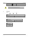
    7 mvd 100 user’s manual inversed 3 (“0” or “1”) “;” etb (0x17) a ttention : t he values for the switching points must be > 0. 6. Type code mvd 10 1 . 3 / 24v 1 2 3 1 connection 1 = plug-in card with 32-pin din strip 3 = version with 20-pin terminal strip 2 = version with 20-pin terminal strip 8 = pl...

  • Page 8

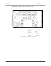
    8 mvd100 user’s manual 7. Connection to 230/115 vac supply voltage figure 7.1 jump wire connections for voltage supply.

  • Page 9

    9 mvd 100 user’s manual due to the continual development of our products, we reserve the right to modify specifications without forewarning. Magtrol inc 70 gardenville parkway buffalo, new york 14224 usa phone: +1 716 668 5555 fax: +1 716 668 8705 e-mail: magtrol@magtrol.Com magtrol sa route de mont...