Makita UC3003A Technical Information
Continuous Rating (W)
Voltage (V)
Model No.
Chain blade
No load chain speed: m/s
Electric brake
Guide bar length: mm (")
Pitch
Chain type
Gauge
Cycle (Hz)
UC3003A
UC3503A
UC4503A
UC4003A
UC3003A, UC3503A, UC4003A, UC4503A
Chain saws 300mm, 350mm, 400mm, 450mm
For European market, the above models have been developed
as upgraded chain saws of the current UC3001A series models.
The new UC3003A seies models feature contnuous rating input
of 2000W while the UC3001A series 1800W.
Additionally, the new series includes Model UC4503A,
450mm (18") chain saw which is not in the lineup of UC3001A
series.
Input
Output
Max. Output (W)
230 - 240
Models No.
Description
PRODUCT
Current (A)
T
ECHNICAL INFORMATION
C
ONCEPT AND MAIN APPLICATIONS
S
pecification
S
tandard equipment
O
ptional accessories
The standard equipment for the tool shown may differ from country to country.
* Chain blade
* Guide bar
P 1 / 8
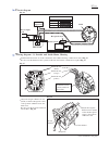
Dimensions: mm ( " )
Width ( W )
Height ( H )
Length ( L )
50 / 60
W
L
H
470 (18-1/2)
215 (8-1/2)
179 (7)
8.8
2,000
2,200
1,100
Clutch
3/8" 46 drive links
91VG
3/8" 52 drive links 3/8" 56 drive links 3/8" 62 drive links
0.050"
300
(12)
350
(14)
400
(16)
450
(18)
Yes
13.3
Yes
* Guide bar scabbard .................... 1 pc.
* Wrench ....................................... 1 pc.


