National Instruments CB-27 Installation Manual
© 1995–2002 National Instruments Corp. All rights reserved.
DAQCard™, National Instruments™, NI™, and ni.com™ are trademarks of National Instruments Corporation. Product and
company names mentioned herein are trademarks or trade names of their respective companies. For patents covering
National Instruments products, refer to the appropriate location: Help»Patents in your software, the patents.txt file
on your CD, or ni.com/patents.
October 2002
320933C-01
CB-27 C
ONNECTOR
B
LOCK
I
NSTALLATION
G
UIDE
This installation guide describes how to connect the CB-27 connector
block. With the CB-27 connector block, you can easily connect analog and
digital signals to the following National Instruments (NI) 27-pin PCMCIA
data acquisition (DAQ) devices:
•
DAQCard-AO-2DC
•
DAQCard-500
•
DAQCard-516
•
NI PCMCIA-4350
Note
Other NI PCMCIA DAQ devices may be compatible with the CB-27. Refer to the
device user manual for compatibility information.
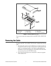
The CB-27 consists of a connector block with 28 screw terminals and a
30-position right angle connector with ejector ears. Each screw terminal
corresponds to a pin number on the 30-position connector. Refer to the
DAQ device user manual for connector pinout information.
Conventions
The following conventions are used in this guide:
»
The » symbol leads you through nested menu items and dialog box options
to a final action. The sequence File»Page Setup»Options directs you to
pull down the File menu, select the Page Setup item, and select Options
from the last dialog box.
This icon denotes a note, which alerts you to important information.
This icon denotes a caution, which advises you of precautions to take to
avoid injury, data loss, or a system crash. When this symbol is marked on
the product, refer to the Read Me First: Safety and Radio-Frequency
Interference document, shipped with the product, for precautions to take.
ni.com


