- DL manuals
- Octel
- Telephone
- XC1000
- Service Manual
Octel XC1000 Service Manual
Summary of XC1000
Page 1
Edition one xc1000 p/n 101–1345–000 service manual.
Page 2
Publication history edition name: edition one edition date: august 1994 printing date: first printing: august 1994 software version: release 4.0 copyright information copyright 1994 by octel communications corporation 1001 murphy ranch road milpitas, california 95035–7912 all rights reserved. No par...
Page 3: Preface
Iii edition one xc1000 service preface the octel communications xc1000 multiple-applications platform provides telephone answering and voice processing to the customer-premise equipment (cpe) marketplace. This manual provides procedures for installing, maintaining, and troubleshooting the xc1000. Th...
Page 4: Compliance Statements
V edition one xc1000 service compliance statements fcc part 15 statement warning: this equipment generates, uses, and can radiate radio frequency (rf) energy and, if not installed and used in accordance with the instruction manual, could cause interference to radio communications. It has been tested...
Page 5
Compliance statements xc1000 service vi edition one xc1000 service if you have any questions about your telephone line, such as how many pieces of equipment you can connect to it, the telephone company will provide this information upon request. In certain circumstances, it could be necessary for th...
Page 6: Caution!
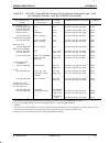
Compliance statements xc1000 service vii edition one xc1000 service fcc requirements for private-line operations to connect xc1000 to the private-line network, provide the telephone company with the quantities and usoc numbers of the required jacks, as shown in table 1. The following is required: - ...
Page 7
Compliance statements xc1000 service viii edition one xc1000 service - this equipment returns answer supervision on all did calls forwarded to the pstn, except when - a call is unanswered. - a busy tone is received. - a reorder tone is received..
Page 8
Contents.
Page 9: Contents
Ix edition one xc1000 service contents one: introduction 1.1 overview 1-1 . . . . . . . . . . . . . . . . . . . . . . . . . . . . . . . . . . . . . . . . . . . . . . . . . . . . . . . . . 1.2 description 1-1 . . . . . . . . . . . . . . . . . . . . . . . . . . . . . . . . . . . . . . . . . . . . . . ...
Page 10
X edition one xc1000 service 3.10 installing the primary smt and optional printer 3-28 . . . . . . . . 3.11 configuring the logic cards 3-30 . . . . . . . . . . . . . . . . . . . . . . . . . . . . . . . . 3.12 setting distribution-board configuration switches 3-42 . . . . 3.13 configuring optional f...
Page 11
Xi edition one xc1000 service 5.7 inspecting and cleaning 5-12 . . . . . . . . . . . . . . . . . . . . . . . . . . . . . . . . . . . . . . 5.8 storing and handling disk drives 5-15 . . . . . . . . . . . . . . . . . . . . . . . . . . 5.9 highlights 5-16 . . . . . . . . . . . . . . . . . . . . . . . ....
Page 12
Xii edition one xc1000 service nine: system utilities 9.1 overview 9-1 . . . . . . . . . . . . . . . . . . . . . . . . . . . . . . . . . . . . . . . . . . . . . . . . . . . . . . . . . 9.2 utility menu access 9-1 . . . . . . . . . . . . . . . . . . . . . . . . . . . . . . . . . . . . . . . . . . . ....
Page 13
Xiii edition one xc1000 service 11.3 multiple smdi link unit (mslu) 11-2 . . . . . . . . . . . . . . . . . . . . . . . . . . . . . . . 11.4 multiple terminal access (mta) 11-6 . . . . . . . . . . . . . . . . . . . . . . . . . . . . . 11.5 busy-out controller 11-6 . . . . . . . . . . . . . . . . . . ...
Page 14
Xiv edition one xc1000 service 13.5 run garbage collect 13-6 . . . . . . . . . . . . . . . . . . . . . . . . . . . . . . . . . . . . . . . . . 13.6 back up system-drive 0 13-7 . . . . . . . . . . . . . . . . . . . . . . . . . . . . . . . . . . . . . . . 13.7 upgrade the hardware 13-9 . . . . . . . ....
Page 15
Xv edition one xc1000 service 14.10 disable the engineering bit 14-35 . . . . . . . . . . . . . . . . . . . . . . . . . . . . . . . . 14.11 purge and convert follow-me-forward mailboxes 14-36 . . . . 14.12 fcp conversion stages 14-36 . . . . . . . . . . . . . . . . . . . . . . . . . . . . . . . . . ...
Page 16
Xvi edition one xc1000 service 16.3 drive copy utilities 16-3 . . . . . . . . . . . . . . . . . . . . . . . . . . . . . . . . . . . . . . . . . . . 16.4 drive replacement utilities 16-17 . . . . . . . . . . . . . . . . . . . . . . . . . . . . . . . . 16.5 drive install utilities 16-21 . . . . . . . ...
Page 17
Xvii edition one xc1000 service eighteen: release 4.0 online upgrade instructions 18.1 overview 18-1 . . . . . . . . . . . . . . . . . . . . . . . . . . . . . . . . . . . . . . . . . . . . . . . . . . . . . . . . 18.2 check the major steps 18-2 . . . . . . . . . . . . . . . . . . . . . . . . . . . ....
Page 18
Xviii edition one xc1000 service twenty: release 4.1 system utilities 20.1 overview 20-1 . . . . . . . . . . . . . . . . . . . . . . . . . . . . . . . . . . . . . . . . . . . . . . . . . . . . . . 20.2 online cdr utility 20-1 . . . . . . . . . . . . . . . . . . . . . . . . . . . . . . . . . . . . . ...
Page 19
1 introduction.
Page 20: Chapter 1
1-iii edition one xc1000 service chapter 1 contents 1.1 overview 1-1 . . . . . . . . . . . . . . . . . . . . . . . . . . . . . . . . . . . . . . . . . . . . . . . . . . . . . . . . . 1.2 description 1-1 . . . . . . . . . . . . . . . . . . . . . . . . . . . . . . . . . . . . . . . . . . . . . . . . ....
Page 21: Introduction
1 1-1 edition one xc1000 service introduction 1.1 overview this xc1000 service manual provides information about the octel xc1000 t multiple-applications platform for use by service personnel who install, main- tain, or troubleshoot the system. The manual is divided into eight sections: section i: i...
Page 22
Introduction 1-2 edition one xc1000 service this manual supports xc1000s using software through release 1.5. Xc1000 can be integrated with up to 16 switches and can support up to seven system manager/service terminals. Each xc1000 can provide up to 30,000 mailboxes. (xc1000s with software releases e...
Page 23
Introduction 1-3 edition one xc1000 service 1 2 3 4 5 6 7 8 9 10 11 12 13 14 15 17 18 16 power supply power supply power supply power supply +5 +5 +12 +12 tic tic tic sp are acp tic tic tic cpu monit or card message file card system file card dlc dlc dlc dlc dlc dlc system system message message spa...
Page 24
Introduction 1-4 edition one xc1000 service smdi data cpu serial buses (data and control) co multiline hunt group line card group 1 atic dlc atic dlc pcm bus ports line card group 2 line card group3 acp* monitor card rdac and remote alarms smt sccs msg file sys file msg drives sys drives (optional) ...
Page 25
Introduction 1-5 edition one xc1000 service 1.2.3 switch integrations xc1000 supports four types of integration: (1) rs-232 integrations, which use separate simplified message desk interface (smdi) data links to the main distribution board or to the asynchronous communications processor (acp), if eq...
Page 26
Introduction 1-6 edition one xc1000 service 1.2.3.4 common channel signaling/signaling system 7 (ccs/ss7) integra- tions. Ccs/ss7 integrations provide a digital transmission for domestic and international signaling applications. Digital transmission eliminates the inherent noise problems that can oc...
Page 27
Introduction 1-7 edition one xc1000 service table 1-1. Platform requirements (concluded). Parameter requirements telephone circuits (concluded) did tic (ground start) 12 e&m tic 12 t1 tic (t1 trunk) 24 e1 tic (e1 trunk) 30 ptic (primary-rate ccs trunk) 30 drive capacity standard drives data capacity...
Page 28
Introduction 1-8 edition one xc1000 service 1.4 highlights - xc1000 provides three basic voice-processing functions to subscribers: telephone answering, voice messaging, and call processing. - xc1000 is available in three configurations: single-cabinet nonredun- dant, dual-cabinet nonredundant, and ...
Page 29: Installation
I i-1 edition one xc1000 service installation the installation section is composed of the following chapters: - chapter two: site preparation - chapter three: platform installation - chapter four: startup and initialization the information in chapter two is for preliminary work that must be complete...
Page 30
2 site preparation.
Page 31: Chapter 2
2-iii edition one xc1000 service chapter 2 contents 2.1 overview 2-1 . . . . . . . . . . . . . . . . . . . . . . . . . . . . . . . . . . . . . . . . . . . . . . . . . . . . . . . . . 2.2 site-entry clearances 2-2 . . . . . . . . . . . . . . . . . . . . . . . . . . . . . . . . . . . . . . . . . 2.3 s...
Page 32
2-iv edition one xc1000 service tables table 2-1. Environmental requirements 2-4 . . . . . . . . . . . . . . . . . . . . . . . . . . . . . . . Table 2-2. Input current requirements 2-6 . . . . . . . . . . . . . . . . . . . . . . . . . . . . . . . Table 2-3. Cable and pin designations for each atic o...
Page 33
2-v edition one xc1000 service figures figure 2-1. Site-preparation task flow 2-1 . . . . . . . . . . . . . . . . . . . . . . . . . . . . . . . . . Figure 2-2. Xc1000 dimensions, crated and uncrated 2-2 . . . . . . . . . . . . . . . . . Figure 2-3. Xc1000 cabinet required clearances (two cabinets, t...
Page 34: Site Preparation
2 2-1 edition one xc1000 service site preparation 2.1 overview before installing a xc1000, the site where the xc1000 will be located must be prepared to meet specific requirements. This chapter contains instructions for preparing the site, including information about equipment location; cabling and ...
Page 35
Site preparation 2-2 edition one xc1000 service - screwdrivers, phillips, #1 and #2 - allen wrench set - cable ties, nylon 2.2 site-entry clearances xc1000 arrives at the site shipped in a crate on a pallet. Consider the following to ensure that the xc1000 can reach the proposed site: - transport th...
Page 36
Site preparation 2-3 edition one xc1000 service restrictions exist for the distance between the switch and xc1000. Consider the following factors when determining the xc1000 location: - allow sufficient clearance around the xc1000 for service personnel to obtain access. Figure 2-3 shows the allowanc...
Page 37
Site preparation 2-4 edition one xc1000 service 2.4.1 air conditioning the air-conditioning system for the room in which xc1000 will be installed should maintain the air temperature and moisture content within the parame- ters shown in table 2-1. Extremely low or high humidity can degrade system rel...
Page 38
Site preparation 2-5 edition one xc1000 service 2.4.3 grounding xc1000 uses a single-point ground for electrical safety and a ground- referenced power input for proper operation of the telephony signaling circuits. When preparing the site, prepare the frame ground wire so that it is ready for attach...
Page 39: Caution!
Site preparation 2-6 edition one xc1000 service available and a power converter is required. The customer is responsible for any equipment needed to provide –48 vdc to the xc1000 site. Table 2-2 lists input current requirements for single- and dual-cabinet xc1000s. Table 2-2. Input current requireme...
Page 40
Site preparation 2-7 edition one xc1000 service 12 11 10 9 8 7 12 11 10 9 8 7 6 5 4 3 2 1 6 5 4 3 2 1 cabinet 2 cabinet 1 power- distribution shelves main backplanes distribution board acp i/o distribution board #1 (optional) acp i/o distribution board #2 (optional) busy-out controller (optional) ma...
Page 41
Site preparation 2-8 edition one xc1000 service prepare cables to be attached to connectors in the following xc1000 locations: - power-distribution shelf - main backplane - main distribution board - acp i/o distribution board #1 (optional) - acp i/o distribution board #2 (optional) - busy-out contro...
Page 42
Site preparation 2-9 edition one xc1000 service 6 5 4 3 2 1 6 5 4 3 2 1 60 in. (152 cm) power distribution shelf main backplane distribution board acp i/o distribution board #1 (optional) acp i/o distribution board #2 (optional) busy-out controller (optional) floor reference cabinet 1 (rear view) fi...
Page 43
Site preparation 2-10 edition one xc1000 service 12 11 10 9 8 7 12 11 10 9 8 7 6 5 4 3 2 1 6 5 4 3 2 1 12 in. (30 cm) 14 in. (36 cm) 26 in. (66 cm) 12 in. (30 cm) 14 in. (36 cm) left frame reference right frame reference 5 in. (13 cm) 60 in. (152 cm) floor reference cabinet 2 cabinet 1 rear view not...
Page 44
Site preparation 2-11 edition one xc1000 service table 2-3. Cable and pin designations for each atic or did tic connector. Xc1000 port function wire color connector pin no. Xc1000 port function wire color connector pin no. A tip wh–bl 26 . . . . . . Bk–br 39 a ring bl–wh 1 . . . . . . Br–bk 14 b tip...
Page 45
Site preparation 2-12 edition one xc1000 service 2.6.2.2 e&m tic cable connections. The e&m tic uses the top row and the lower row of25-pair female connectors on the main backplane (allocated for tic port a through port f and port g through port l, respectively). Determine the cable length as follow...
Page 46
Site preparation 2-13 edition one xc1000 service table 2-5 and table 2-6 show the e&m trunk connections between the switch and the logic-bay backplane. The two rows of connectors on the backplane are referred to as group a (table 2-5) and group b (table 2-6), with the upper connectors being group a ...
Page 47
Site preparation 2-14 edition one xc1000 service table 2-6. Cable connections to the group b main-backplane connectors for e&m tics. Xc100 0 port function wire color b connector pin no. Xc1000 port function wire color b connector pin no. G t wh–bl 26 j t bk–gr 38 g r bl–wh 1 j r gr–bk 13 g t1 wh–or ...
Page 48
Site preparation 2-15 edition one xc1000 service table 2-8 correlates the t1 tic ports, the t1 tic main-backplane connectors, and the connector channels. Each cable carries the 24 channels for one t1 trunk to one tic connector on the main backplane. The cables to the tic1, tic3, and tic5 connectors ...
Page 49
Site preparation 2-16 edition one xc1000 service determine the cabling for an e1 tic as follows: 1. Use either a 75-ohm coaxial cable or a 120-ohm symmetrical-pair cable for connection with an e1 tic adapter board (part number 044–2059–000 for a 75-ohm connection and 044–2059–001 for a 120-ohm conne...
Page 50
Site preparation 2-17 edition one xc1000 service figure 2-8 shows the dimensions to e1 tic or ptic connectors on the main backplane. 12 11 10 9 8 7 12 11 10 9 8 7 6 5 4 3 2 1 6 5 4 3 2 1 26 in. (66 cm) left frame reference right frame reference 5 in. (13 cm) 60 in. (152 cm) floor reference cabinet 2...
Page 51
Site preparation 2-18 edition one xc1000 service cable clamp (#6 screw) 3 / 8 –inch spacer screw, 6–32 flat washer top internal-tooth lockwasher (2x) screw, 4–40 flat washer 1 1 / 4 –inch (2x) (2x) cable clamp (#6 screw) 3 / 8 –inch spacer flat washer top internal-tooth lockwasher (2x) flat washer 1...
Page 52
Site preparation 2-19 edition one xc1000 service 2.6.3.1 smt connections. The smt is normally connected to the xc1000 at the j50 connector on the distribution board, using a male-to-male db25 cable. The rs-232-c interface uses pins and signals listed in table 2-9. Table 2-9. Rs-232-c pins for the sm...
Page 53
Site preparation 2-20 edition one xc1000 service 26 in. (66 cm) 24 in. (61 cm) 23 in. (59 cm) 21 in. (54 cm) 9 in. (23 cm) left frame reference right frame reference 37 in. (94 cm) 41 in. (104 cm) cabinet 1 rear view data-link port connectors external-alarm connector j25 notes: - data-link port conn...
Page 54
Site preparation 2-21 edition one xc1000 service table 2-11. J25 pin assignments for the amphenol plug for remote alarms. Alarm category normally closed (nc) normally open (no) common contact (c) alarm category pin no. Wire color pin no. Wire color pin no. Wire color nsa 20 sl–yl 21 bl–vo 45 yl–sl s...
Page 55
Site preparation 2-22 edition one xc1000 service 2.6.3.5 data-module x.25 connection to xc1000. X.25 data links from the data module connect to j48 (channel 0) or j47 (channel 1) on the main distribution board. Use the x.25 cable assemblies (octel p/n 057–1174–000) supplied with the data module. Fig...
Page 56
Site preparation 2-23 edition one xc1000 service 26 in. (66 cm) 23 in. (58 cm) 16 in. (41 cm) left frame reference right frame reference 32 in. (81 cm) cabinet 1 rear view note: acp i/o distribution board connectors on 1-inch (2.5-cm) centers. 23 in. (58 cm) 19 in. (48 cm) integration data-link port...
Page 57
Site preparation 2-24 edition one xc1000 service table 2-13. The acp mta connector assignments on acp i/o distribution board 2. Mta terminal link no. Connector no. 1 j111 2 j112 3 j113 4 j114 5 j115 6 j116 7 j117 2.6.5 busy-out controller cables for the busy-out-controller relay closures are connect...
Page 58
Site preparation 2-25 edition one xc1000 service table 2-14. Busy-out controller connector (j1) pin assignments (concluded). J1 connector make-busy wire pair j1 connector channel wire no. Wire color wire no. Wire color relay contact 14 40 bk–br 15 br–bk relay contact 15 41 bk–sl 16 sl–bk relay conta...
Page 59
Site preparation 2-26 edition one xc1000 service 2.7 floor-mount installation the xc1000 cabinets are secured to a floor mount. The floor mount can be bolted onto a concrete floor or onto a raised floor. Figure 2-14 shows the floor-mount dimensions. Outline of xc1000 doors and side-panels front main...
Page 60
3 platform installation.
Page 61: Chapter 3
3-iii edition one xc1000 service chapter 3 contents 3.1 overview 3-1 . . . . . . . . . . . . . . . . . . . . . . . . . . . . . . . . . . . . . . . . . . . . . . . . . . . . . . . . . 3.2 ensuring equipment and personnel safety 3-1 . . . . . . . . . . . . . . . . 3.2.1 electrical safety 3-2 . . . . ....
Page 62
3-iv edition one xc1000 service 3.10 installing the primary smt and optional printer 3-28 . . . . . . . . 3.10.1 smt installation 3-28 . . . . . . . . . . . . . . . . . . . . . . . . . . . . . . . . . . . . . . . . . . . 3.10.2 printer installation 3-29 . . . . . . . . . . . . . . . . . . . . . . . ...
Page 63
3-v edition one xc1000 service tables table 3-1. Parts for the dual-cabinet installation kit 3-8 . . . . . . . . . . . . . . . . . . . Table 3-2. Integration-data-link connections on the acp i/o distribution boards 3-27 . . . . . . . . . . . . . . . . . . . . . . . . . . . . . . . Table 3-3. The mta...
Page 64
3-vi edition one xc1000 service figure 3-8. Atic or did tic telephone-line connections 3-19 . . . . . . . . . . . . . Figure 3-9. E&m tic telephone-line connections 3-20 . . . . . . . . . . . . . . . . . . . . . Figure 3-10. T1 tic telephone-line connections 3-21 . . . . . . . . . . . . . . . . . . ...
Page 65: Platform Installation
3 3-1 edition one xc1000 service platform installation 3.1 overview installing the xc1000 involves ensuring equipment and personnel safety; obtaining all required tools; unpacking and inspecting the equipment; positioning the cabinet; attaching the accessories; installing the auxiliary shelf; connec...
Page 66: Caution!
Platform installation 3-2 edition one xc1000 service 3.2.1 electrical safety before connecting the –48 vdc primary-power leads to the xc1000, take the following precautions: - make sure that the –48 vdc branch circuit breaker is off or fuses are removed, as applicable. - always connect the ground le...
Page 67: Caution!
Platform installation 3-3 edition one xc1000 service do not turn on the power to the xc1000 until the installa- tion is complete and has been checked. To do otherwise could damage equipment components. Caution! - although tics and digital line cards (dlcs) are hot-pluggable and can be removed and re...
Page 68
Platform installation 3-4 edition one xc1000 service 3.2.3 environmental safety the xc1000 must operate within safe environmental parameters. Environ- mental requirements are described in section 2.4. The xc1000 depends on the positive air pressure created by the air flow within the cabinet to maint...
Page 69
Platform installation 3-5 edition one xc1000 service 3.4 inspecting and unpacking the xc1000 after the crated xc1000 has been delivered, inspect the cabinet crate and the other containers for signs of damage before unpacking the equipment. Also inspect the equipment during the unpacking process. Any...
Page 70: Warning!
Platform installation 3-6 edition one xc1000 service 4. Open each shipping container and verify the contents against the packing slips. Notify octel communications and the carrier of any discrepancies. Return all damaged parts to octel using the procedures found in appendix b. 3.4.2 uncrating the xc...
Page 71: Warning!
Platform installation 3-7 edition one xc1000 service 3. Remove the remaining three sides and the top of the crate. 4. Using a 9 / 16 -inch socket wrench, remove the ramp from the inside of the front well. Set the ramp aside. 5. Remove the four 9 / 16 -inch bolts that secure the xc1000 cabinet to the...
Page 72
Platform installation 3-8 edition one xc1000 service 3.5.1 dual-cabinet connection if installing a single-cabinet xc1000, proceed to the next section. The first stage of installing a dual-cabinet xc1000 is to connect the cabinets. A dual-cabinet installation kit is required. The kit is shipped with ...
Page 73
Platform installation 3-9 edition one xc1000 service 3. Remove the burgundy-colored slide panel that covers the circuit breakers on the power-distribution shelf by pulling it away from the frame. 4. Open the front and rear doors, remove any packing materials, and remove the grounding straps by pulli...
Page 74
Platform installation 3-10 edition one xc1000 service power-conduit fitting nut power-conduit end fitting conduit frame-alignment plug frame tubing conduit fitting primary cabinet (cabinet 1) power-terminal block for cabinet 2 main backplane main backplane pins main distribution board to connector j...
Page 75
Platform installation 3-11 edition one xc1000 service power- distribution assembly inspection cover panel power-supply cables front mounting screws, 2 places figure 3-5. The power-distribution assembly. 5. From the rear of cabinet 1, pull the power-distribution assembly out of the power-distribution...
Page 76: Caution!
Platform installation 3-12 edition one xc1000 service 3.5.1.3 connecting the intercabinet signal cables. Refer to figure 3-5 and per- form the following steps to connect the power and signal cables between cabinet 1 (primary cabinet) and cabinet 2 (expansion cabinet): 1. On cabinet 1, remove the cov...
Page 77: Caution!
Platform installation 3-13 edition one xc1000 service 14. Secure the p51 signaling cable to the cabinet frames with cable ties, so that it does not hang loosely. 15. Connect the p53 signaling cable (p/n 057–1181–000) to j53 on the cabinet 1 distribution board. 16. Connect the other end of the p53 ca...
Page 78: Caution!
Platform installation 3-14 edition one xc1000 service 8. Attach the power cable labeled negative to the terminal block marked –. Secure the power cable with one of the screws removed in step 6. 9. Secure the cover on the cabinet 2 power-distribution shelf using the hardware removed in step 2. Do not...
Page 79
Platform installation 3-15 edition one xc1000 service ÎÎÎÎÎÎÎÎÎÎÎÎÎÎÎÎÎÎÎÎÎÎ ÎÎÎÎÎÎÎÎÎÎÎÎÎÎÎÎÎÎÎÎÎÎ ÎÎÎÎÎÎÎÎÎÎÎÎÎÎÎÎÎÎÎÎÎÎ ÎÎÎÎÎÎÎÎÎÎÎÎÎÎÎÎÎÎÎÎÎÎ ÎÎÎÎÎÎÎÎÎÎÎÎÎÎÎÎÎÎÎÎÎÎ ÎÎÎÎÎÎÎÎÎÎÎÎÎÎÎÎÎÎÎÎÎÎ ÎÎÎÎÎÎÎÎÎÎÎÎÎÎÎÎÎÎÎÎÎÎ ÎÎÎÎÎÎÎÎÎÎÎÎÎÎÎÎÎÎÎÎÎÎ ÎÎÎÎÎÎÎÎÎÎÎÎÎÎÎÎÎÎÎÎÎÎ ÎÎÎÎÎÎÎÎÎÎÎÎÎÎÎÎÎÎÎÎÎÎ cap screw should...
Page 80
Platform installation 3-16 edition one xc1000 service 11. Reattach the floor-mount angle brackets to the cabinet. Do not tighten these bolts completely; leave them just short of binding. The holes in the floor, insulator, and angles should now be aligned. Adjust as necessary. 12. Place a shoulder wa...
Page 81: Warning!
Platform installation 3-17 edition one xc1000 service to section 2.6 for details about cable preinstallation. Make –48 vdc and return connections to the cabinet with #2-awg wire. Use one connection for both single- and dual-cabinet versions. Perform the following steps to connect power to the xc1000...
Page 82: Caution!
Platform installation 3-18 edition one xc1000 service for proper operation of telephone signaling circuits and equipment, the –48 vdc return must be strapped to the central office main-ground bus (earth-ground reference). This strap is usually installed close to the power source or distribution pane...
Page 83
Platform installation 3-19 edition one xc1000 service cabinet 2 main backplane tic6 tic5 tic4 tic3 tic2 tic1 tic6 tic5 tic4 tic3 tic2 tic1 cabinet 1 main backplane tic12 tic11 tic10 tic9 tic8 tic7 tic12 tic11 tic10 tic9 tic8 tic7 12a 12l 11a 11l 10a 10l 9a 9l 8a 8l 7a 7l 6a 6l 5a 5l 4a 4l 3a 3l 2a 2...
Page 84
Platform installation 3-20 edition one xc1000 service cabinet 2 main backplane tic6 tic5 tic4 tic3 tic2 tic1 tic6 tic5 tic4 tic3 tic2 tic1 cabinet 1 main backplane tic12 tic11 tic10 tic9 tic8 tic7 tic12 tic11 tic10 tic9 tic8 tic7 12a 12f 11a 11f 10a 10f 9a 9f 8a 8f 7a 7f 6a 6f 5a 5f 4a 4f 3a 3f 2a 2...
Page 85
Platform installation 3-21 edition one xc1000 service tic12 tic11 tic10 tic9 tic8 tic7 11a 11l 12a 12l 9a 9l 10a 10l 7a 7l 8a 8l tic6 tic5 tic4 tic3 tic2 tic1 tic6 tic5 tic4 tic3 tic2 tic1 5a 5l 6a 6l 3a 3l 4a 4l 1a 1l 2a 2l tic12 tic11 tic10 tic9 tic8 tic7 cabinet 2 main backplane cabinet 1 main ba...
Page 86
Platform installation 3-22 edition one xc1000 service tic6 tic5 tic4 tic3 tic2 tic1 tic6 tic5 tic4 tic3 tic2 tic1 cabinet 1 main backplane e1 or ptic interface figure 3-11. E1 tic or ptic telephone-line connections to the e1 tic or ptic adapter boards. Perform the following steps to connect the tele...
Page 87
Platform installation 3-23 edition one xc1000 service cable clamp (#6 screw) screw, 6–32 by 3 / 8 –inch spacer flat washer top internal-tooth lockwasher (2x) flat washer screw, 4–40 by 1 1 / 4 –inch (2x) (2x) cable clamp (#6 screw) spacer flat washer top internal-tooth lockwasher (2x) flat washer (2...
Page 88
Platform installation 3-24 edition one xc1000 service c. If a shielded ground is required, attach a grounding wire to w5. D. Bundle the wires connected to terminals w1, w2, w3, w4, and, if used, w5, and secure them in the cable clamp. Attach the clamp to the board with a number 8 screw. 4. Connect t...
Page 89
Platform installation 3-25 edition one xc1000 service the cables should have been marked when they were measured and terminated during the site-preparation stage (refer to section 2.6.4). Some of these connections might not be required for some xc1000 configurations; refer to the system-configuratio...
Page 90
Platform installation 3-26 edition one xc1000 service terminals 1–7 acp distribution 12 11 10 4 3 2 1 0 acp distribution 15 14 13 9 8 7 6 5 acp i/o distribution board #1 integration-data-link connections links 1-5, 11,12, and 13 integration-data-link connections links 6-10, 14, 15, and 16 acp i/o di...
Page 91
Platform installation 3-27 edition one xc1000 service table 3-2. Integration-data-link connections on the acp i/o distribution boards. Integration data-link no. Acp i/o distribution board connector no. Functions 1 1 j103 transmit data (txd), receive data (rxd), data-carrier detect (dcd), request to ...
Page 92
Platform installation 3-28 edition one xc1000 service 3.9.2 busy-out-controller cable connections if the xc1000 has the busy-out-controller feature, it is located in the lower, back left corner of cabinet 1. The cable for the busy-out controller connects to j1 on the rear of the busy-out controller,...
Page 93
Platform installation 3-29 edition one xc1000 service 3. Connect one end of the the keyboard cable to the receptacle on the back of the keyboard. Connect the other end to the receptacle labeled keybd on the back of the terminal. 4. Connect and secure the rs-232-c db25 cable labeled datacomm to the d...
Page 94: Caution!
Platform installation 3-30 edition one xc1000 service 7. For the dl1200, perform the following: a. Loosen the large screw at the right rear corner of the printer. Slide the cover toward the rear of the printer. B. Locate the paper-release lever at the top left side of the printer. Pull the lever for...
Page 95
Platform installation 3-31 edition one xc1000 service line-card line-card line-card cabinet 1 cabinet 2 1 2 3 4 5 6 7 8 9 10 11 12 13 14 15 16 17 18 19 20 21 22 23 24 25 26 27 28 29 30 31 32 33 34 35 36 system file card message file card monitor card central processor unused acp tic1 dlc tic2 (or un...
Page 96
Platform installation 3-32 edition one xc1000 service figure 3-17 shows the logic-bay slots where atics or did tics are located. Make sure that the logic cards are in the correct slots and are inserted properly. Table 3-4 shows the wiring from the backplane connectors to the atic and did tic ports. ...
Page 97
Platform installation 3-33 edition one xc1000 service 3.11.2 e&m tic configuration e&m tics convert incoming analog voice to digital signals. Each e&m tic is connected to one dlc. There are two e&m tics and two dlcs in a line-card group. Figure 3-18 shows the e&m tic and dlc slot locations. Two sets...
Page 98
Platform installation 3-34 edition one xc1000 service table 3-6. E&m tic, revision a, signaling-switch settings. E&m tic switch settings signaling type ux07 ux08 type 1 2 3 4 5 6 7 8 1 2 3 4 i off on off on off on off on off on on off i on off on off on off on off on off off off ii off on off on off...
Page 99
Platform installation 3-35 edition one xc1000 service t1 tic u5t u5u u2u j1 j2 1 2 5 6 7 8 3 4 extractor lever 1 2 3 1 2 3 on off figure 3-20. T1 tic showing line-configuration switches. 1. Make sure that the rom chips are firmly seated in the sockets at u5u (high byte) and u5t (low byte). Pin 1 of ...
Page 100
Platform installation 3-36 edition one xc1000 service 3.11.4 e1 tic configuration e1 tics support an e1 interface that provides a digital transmission facility of 2.048 mb/s. An e1 tic provides the interface to support 32 dlc channels; therefore, three dlcs are required for each line-card group cont...
Page 101
Platform installation 3-37 edition one xc1000 service j3 u2v alarm leds diagnostic test jacks u3d u7b j2 u8f figure 3-22. Location of switches and jumpers on the e1 tic. Table 3-8. E1 tic termination-connection configuration. Switch designation switch settings designation 1 2 3 4 120-ohm coaxial con...
Page 102
Platform installation 3-38 edition one xc1000 service 4. At j3, install a jumper across pins 1 and 2 (off) to disable pulse- code-modulation (pcm) loopback. Install the jumper across pins 2 and 3 (on) to enable pcm loopback. For normal operation, the jumper must be across pins 1 and 2. If there is n...
Page 103
Platform installation 3-39 edition one xc1000 service table 3-9. Dip-switch settings for ptics. Switch designation switch settings designation 1 2 3 4 e1 mode at 120 ohms u32l off off off off u30d on off on on u11s on off off on u12s on off off on u9x on off off off u6x off off off off e1 mode at 75...
Page 104
Platform installation 3-40 edition one xc1000 service j3 u6x align leds diagnostic test jacks alarm leds u9x u11s u12s u32l u30d p101a p101b p2 figure 3-23. Locations of switches and jumpers on the ptic. Before installing the f10 system and message file cards, verify that the memory-configuration sw...
Page 105
Platform installation 3-41 edition one xc1000 service s1 figure 3-25. C10 cpu memory-configuration switch settings for 8 mb. The c10 cpu can be upgraded to 16 mb of memory by replacing the eight 1-mb single in-line memory modules (simms) with four higher capacity 4-mb simms. (refer to installation i...
Page 106
Platform installation 3-42 edition one xc1000 service 3.11.8 monitor card configuration the monitor card contains the four switches shown in figure 3-28 and identified in table 3-11. These switches enable or disable the oos, sa, and nsa remote alarms. 3.12 setting distribution-board configuration sw...
Page 107
Platform installation 3-43 edition one xc1000 service table 3-11. Monitor card audible-alarm- configuration-switch settings. Switch number switch setting switch function 1 on enables oos alarm off disables oos alarms 2 on enables sa alarms off disables sa alarms 3 on enables nsa alarms off disables ...
Page 108
Platform installation 3-44 edition one xc1000 service table 3-12. S2 alarm configuration switches. Single cabinet dual cabinet switch cabinet purpose switch cabinet purpose 1 1 +5 vdc redundant 1 1 +5 vdc redundant 2 1 +12 vdc redundant 2 1 +12 vdc redundant 3 1 –48 vdc telecom present 3 1 –48 vdc t...
Page 109
Platform installation 3-45 edition one xc1000 service table 3-14. Busy-out-controller configuration-switch settings. Switch description setting a setting description comments 1 relay 0 sense on seek –48 vdc from the scan point set switch 1 on when switch 2 is set off ignore –48 vdc from the scan poi...
Page 110
Platform installation 3-46 edition one xc1000 service rdac, it is not recommended for or supported on pc-based applications. These applications include octel call detail records (octel pc/cdr) or aspenanalyst . The rdac contains a built-in power supply and four sockets for connecting the terminal an...
Page 111
Platform installation 3-47 edition one xc1000 service 3.15 highlights - safety is a primary consideration when installing and operating the xc1000. - when unpacking the xc1000 equipment, carefully check the packing slip. Any damage to the equipment must be reported to octel and the shipper. - the xc...
Page 112
4 startup and initialization.
Page 113: Chapter 4
4-iii edition one xc1000 service chapter 4 contents 4.1 overview 4-1 . . . . . . . . . . . . . . . . . . . . . . . . . . . . . . . . . . . . . . . . . . . . . . . . . . . . . . . . . 4.2 initializing the smt 4-1 . . . . . . . . . . . . . . . . . . . . . . . . . . . . . . . . . . . . . . . . . . . . ...
Page 114
4-iv edition one xc1000 service 4.4.3 assigning system manager information 4-32 . . . . . . . . . . . . . . . . . . . . . 4.4.3.1 primary system manager 4-32 . . . . . . . . . . . . . . . . . . . . . . . . . . . 4.4.3.2 secondary system manager 4-33 . . . . . . . . . . . . . . . . . . . . . . . . 4....
Page 115
4-v edition one xc1000 service tables table 4-1. Dl1200 printer-setup functions 4-7 . . . . . . . . . . . . . . . . . . . . . . . . . . . Table 4-2. Examples of ml320 menu settings 4-9 . . . . . . . . . . . . . . . . . . . . . . . . . Table 4-3. Hp 700/43 setup-mode function-key descriptions 4-12 . ...
Page 116
4-vi edition one xc1000 service figure 4-14. Ipl1 and ipl2 display 4-20 . . . . . . . . . . . . . . . . . . . . . . . . . . . . . . . . . . . . (a) nonredundant xc1000 4-20 . . . . . . . . . . . . . . . . . . . . . . . . . . . . . . . . . (b) redundant xc1000 4-20 . . . . . . . . . . . . . . . . . ....
Page 117: Startup and Initialization
4 4-1 edition one xc1000 service startup and initialization 4.1 overview after the xc1000 has been installed, external cables connected, and internal switches and connections verified, the xc1000 can be started up and initialized. Several preliminary steps must be performed before the xc1000 is oper...
Page 118
Startup and initialization 4-2 edition one xc1000 service 4.2.1 turning on the smt perform the following steps to turn on the terminal: 1. Make sure that the terminal is installed correctly and connected to j50 on the xc1000 distribution board. 2. Press the power button to turn the terminal on. List...
Page 119: Caution!
Startup and initialization 4-3 edition one xc1000 service - backspace key. The backspace key erases the character to the left while moving the cursor to the left. Use this key to edit existing data. The cursor-left key operates in the same fashion. - break key. Use the break key to cancel a data ent...
Page 120
Startup and initialization 4-4 edition one xc1000 service - delete key. Use the shift and del keys to erase all characters within the current data-entry field. - enter or return key. Use the enter key or the return key for a number of functions: - pressing enter establishes a command when pressed af...
Page 121
Startup and initialization 4-5 edition one xc1000 service - to set up continuous printing, use the print-echo function. To use the print-echo function, use the following keys: - for the vt102, hold down the ctrl key and press the print key to start or stop the print echo. - for the vt220, hold down ...
Page 122
Startup and initialization 4-6 edition one xc1000 service ***** offline setup mode ***** – the red cursor indicates the option to be selected. – the selected option is underlined. – “save&end” function must be selected to exit setup mode. – following list shows how buttons function in setup mode: bu...
Page 123
Startup and initialization 4-7 edition one xc1000 service *** setup parameters *** > func. Item option menu 1 emulate dpl24c+ menu 1 font cour 10 menu 1 quality letter menu 1 pitch 10 cpi menu 1 line sp 6 lpi menu 1 char–w normal menu 1 char–h normal menu 1 attrib none menu 1 page lg 11.0 in menu 1 ...
Page 124
Startup and initialization 4-8 edition one xc1000 service the system manager report 3, short form subscriber statistics, is too wide to be printed on 8 1 / 2 -inch-wide paper. Either wide computer paper or printing in condensed print mode is required. Use the procedure in section 4.2.3.1 to change t...
Page 125
Startup and initialization 4-9 edition one xc1000 service 4.2.4 establishing okidata ml320 printer parameters no dip switches or other hardware changes need to be made to the ml320. The printer is completely software-configured, using the printer’s setup mode. Perform the following steps to set up t...
Page 126
Startup and initialization 4-10 edition one xc1000 service table 4-2. Examples of ml320 menu settings (concluded). Vertical control line spacing 6 lpi form tear-off off skip over perforation no auto lf no auto cr no auto feed xt invalid page length 11” cut sheet page length 11” symbol sets character...
Page 127
Startup and initialization 4-11 edition one xc1000 service 9. Make sure that the printer is off-line and test the printer as follows: a. Turn off the printer. B. Press the tof/quiet button while turning on the power. The ml320 prints a sample of the default print style. C. To end the self-test, turn...
Page 128
Startup and initialization 4-12 edition one xc1000 service 2. From the setup-mode screen, press the f1 key to display the user setup menu, as shown in figure 4-7. When the menu appears, the cursor is in the first field. Refer to table 4-3 for a description of the function keys displayed at the botto...
Page 129
Startup and initialization 4-13 edition one xc1000 service 3. Confirm that the parameters displayed on the menu are the same as the parameters shown in figure 4-7. If the values on the screen differ, change them to the values shown in figure 4-7 by pressing the spacebar or f2 until the correct value...
Page 130
Startup and initialization 4-14 edition one xc1000 service baud rate data length parity stop bits communication recv pace xmit pace cts dsr cd monitor line 9600 (or 1200) 8 bits none 1 full duplex xon/xoff xon/xoff ignore ignore ignore off a f k b g c h d i e j l q m r n s o t p baud rate data lengt...
Page 131
Startup and initialization 4-15 edition one xc1000 service 12. Establish the keyboard parameters, as shown in figure 4-10. If the parameters on the screen are not the same as those in figure 4-10, use the procedures shown in step 4 to move to the incorrect field and press the space bar or f2 until t...
Page 132
Startup and initialization 4-16 edition one xc1000 service 3. Press the space bar to change the displayed value. Refer to figure 4-11 for terminal parameters, unless the switch or location considerations require other, specific settings. Move to the various fields within each menu as follows: - pres...
Page 133
Startup and initialization 4-17 edition one xc1000 service table 4-4. Entries for the vt102 terminal setup. Entry value definition modem p 8n 8 data bits per character, no parity t 1200 or 9600 transmit speed (baud rate) r 1200 or 9600 receive speed (baud rate) fdx a . . . Full duplex, no eia modem ...
Page 134
Startup and initialization 4-18 edition one xc1000 service table 4-5. Entries for the vt220 terminal setup. Parameter value control data bits 7 communications transmit/receive speed (baud rate) 9600 or 1200 transmit/receive pace (handshake) xon/xoff data bits 8 parity none number of stop bits 1 prin...
Page 135
Startup and initialization 4-19 edition one xc1000 service *** smt [baud rate] *** 4 second wait for mta connections to boot.... *** sending mta port #0 a “go to broadcast mode” msg (0x10, 0x01 prom resident test demon, production version cpu card self–test status: cpu test passed . . . . . . . . . ...
Page 136
Startup and initialization 4-20 edition one xc1000 service initial program load phase 1 begins found message file card at (bank:slot) 0:1 found system file card at (bank:slot) 0:6 scrubbing all ”known” dram memory (00000000–01000000) call ipl2 bootloader syncing . . . Ipl2 root version so1200.0 syst...
Page 137
Startup and initialization 4-21 edition one xc1000 service to abort the loading routine, turn off the xc1000 by switching the main circuit breaker to off. To stop the test results from scrolling up the screen, press ^s. To resume the scrolling, press ^q. 4.3.3 checking the file-card status after the...
Page 138
Startup and initialization 4-22 edition one xc1000 service the system file card uses the data in these tables to locate the drives during initialization. The install table on system drive 0 contains information about both system drives. The system file card writes the drive’s serial number to the in...
Page 139
Startup and initialization 4-23 edition one xc1000 service 2. Count the 1’s from the right. Each 1 represents a drive. In this case, there are two system drives running, because the codes were displayed in the primary file card status. If the least-significant 1 is a zero, then system drive 0 is not...
Page 140: Caution!
Startup and initialization 4-24 edition one xc1000 service the boot command entered after this prompt instructs the file card to load the operating program from disk to cpu memory. The following are valid entries used to boot the xc1000: a directs the xc1000 to reboot automatically after any type of...
Page 141
Startup and initialization 4-25 edition one xc1000 service 4.3.5.2 card configuration. The cpu sends a broadcast message to all cards connected to the control bus, directing them to identify themselves. The screen shows the card configuration after the file cards, acp, and the digital line cards (dl...
Page 142
Startup and initialization 4-26 edition one xc1000 service the entry for a redundant xc1000 that booted from side b would appear as follows: –f–m–ma –l–l–l–l–l–l– – – – – – –l–l–l–l–l–l the first abbreviation shown (figure 4-16 example for a redundant xc1000) is f, followed by a dash, then an m, a d...
Page 143
Startup and initialization 4-27 edition one xc1000 service the file system attempts to build the dial-by-name table during this part of the boot process. The file system searches for mailboxes but, since there are none, displays menu 0 later in the process. Figure 4-17 shows the display confirming t...
Page 144: Caution!
Startup and initialization 4-28 edition one xc1000 service 4.4 completing the first-time setup in menu 0 menu 0 appears only once, when xc1000 is initialized. Most of the entries in menu 0 can be changed in menu 1; however, two fields cannot be changed or updated,unless xc1000 is reinitialized: be c...
Page 145
Startup and initialization 4-29 edition one xc1000 service copyrights e 1984-1991, octel communications corporation menu 0 – first-time setup company information... Name: address: phone (include area code): : : figure 4-19. First screen of menu 0 – first-time setup. 3. Enter the company telephone nu...
Page 146: Caution!
Startup and initialization 4-30 edition one xc1000 service enter information specific to the xc1000 platform. Vpmod means voice- processing module, but when vpmod is used on a xc1000 screen, it refers to the xc1000. Perform the following steps to complete menu 0.1: 1. Locate the xc1000’s 5-digit ser...
Page 147
Startup and initialization 4-31 edition one xc1000 service 7. Enter the code for the type of telephone system in the type of telephone system vpmod is connected to: field. The four valid codes are as follows: 1 – north american 2 – australian 3 – new zealand 4 – united kingdom the code selected cann...
Page 148
Startup and initialization 4-32 edition one xc1000 service 12. Enter n in the message waiting special (certain pbx’s only): field. (the default value is n.) this field, which is applicable only for integration to at&t’s system 85, is not currently supported on xc1000. 13. In the acp used for integra...
Page 149: Caution!
Startup and initialization 4-33 edition one xc1000 service 2. Enter the number of the mailbox reserved for the primary system manager in the mailbox number: field. The number of digits must be the same as established in the second screen of menu 0 (menu 0.1). 3. In the initial mailbox password: fiel...
Page 150
Startup and initialization 4-34 edition one xc1000 service 2. The initial default for the mailbox number: field is 411 for a 3-digit mailbox. For mailboxes with more digits, xc1000 adds 4stothe beginning of the mailbox number until the correct number of digits has been reached. Leave the default set...
Page 151: Caution!
Startup and initialization 4-35 edition one xc1000 service - accurate status-code logging - outcalling - networking once menu 0 is complete, it cannot be accessed again. Make sure that information entered into the menu 0 fields is correct when it is entered. Caution! Before the main menu can be acce...
Page 152
Startup and initialization 4-36 edition one xc1000 service six submenus are required for the 144 ports available on xc1000. The first submenu, menu 4.1, is shown in figure 4-24. Menu 4 – port assignments pt extension/ phone no. I o t m n p ln tp d pt gp pt extension/ phone no. I o t m n p ln tp d pt...
Page 153
Startup and initialization 4-37 edition one xc1000 service 11. Did, dtmf, immediate start 12. Did, dtmf, wink start 15. In-band, e&m, dtmf, immediate start, 4 wires 16. In-band, e&m, dtmf, wink start, 4 wires 35. Smdi, atic loop start 49. Generic atic, ground start, dial tone disconnect 52. Smdi, at...
Page 154
Startup and initialization 4-38 edition one xc1000 service 3. After entering the correct line type, press the print send key. The cursor moves to the next field that needs a new entry, which can be the first entry under the d column or the next entry in the lntp column. An entry in the d column is r...
Page 155
Startup and initialization 4-39 edition one xc1000 service - an extension number of a business telephone system - a direct-dial number in a switch - a logical terminal number (ltn) that is used with some integrations perform the following steps to enter port information in menu 4: 1. Enter the telep...
Page 156
Startup and initialization 4-40 edition one xc1000 service designating a port for pager outcalling does not prevent that port from performing other functions. The system manager can select one or multiple ports to support pager outcalling. If a pager port has not been designated, the pager outcall w...
Page 157
Startup and initialization 4-41 edition one xc1000 service at the main menu, enter the number of the menu needed to complete a specific task and press the enter key. When establishing xc1000 operating parameters and subscriber profiles for the first time, enter the menus in the order shown on the ma...
Page 158
Startup and initialization 4-42 edition one xc1000 service menu 1 – system parameters – installation information – : company name : company address: company phone number (include area code): vpmod phone number (include area code): extension: number of rings for local and long distance calls (used fo...
Page 159
Startup and initialization 4-43 edition one xc1000 service 4. In the number of rings for on-pbx calls (used for ecp): field, enter a number that is one less than the number of ring cycles allowed on the centrex before forwarding calls to xc1000. The maximum number is 20; the minimum is 2. If xc1000 ...
Page 160: Caution!
Startup and initialization 4-44 edition one xc1000 service 4.8.1 setting transfer, outcall, and pager sequences to establish dialing sequences for transferring calls, outcalls, and outcalls to pagers, perform the following steps: 1. Select 1 from the primary menu 6 screen, and the submenu (also know...
Page 161
Startup and initialization 4-45 edition one xc1000 service 4. To enable xc1000 to transfer a call, enter the transfer-to-telephone sequence in the dialing sequence to transfer a call: field. Enter an f (flash), transfer-code feature (if required), and n for the number to be dialed (the transfer targ...
Page 162: Caution!
Startup and initialization 4-46 edition one xc1000 service sending amis analog messages to international destina- tions increases a company’s telephone bill. Make sure that the entries in the dialing sequence for international calls: field use cost-effective means for placing calls to international ...
Page 163
Startup and initialization 4-47 edition one xc1000 service table 4-8. Pager-dialing sequence codes. Code name description a answer detect xc1000 waits to detect a ring cycle from the paging terminal. To establish the ring cycle, xc1000 must receive a minimum of three full ringback tones. Because mos...
Page 164
Startup and initialization 4-48 edition one xc1000 service table 4-8. Pager-dialing sequence codes (concluded). Code name description d disconnect xc1000 disconnects the port. Every pager dialing sequence should end with the d code. If the d code is not in the pager dialing sequence, xc1000 plays ou...
Page 165
Startup and initialization 4-49 edition one xc1000 service 1. Depending on the integration in the maximum time before first digit received:field, enter the maximum time allowed, in milliseconds, before the first digit is received from the switch on forwarded calls. If xc1000 does not receive a digit...
Page 166
Startup and initialization 4-50 edition one xc1000 service table 4-9. Xc1000 cpu serial channels and physical connectors. Cpu channel physical connector number function 1 j44 integration/smt 2 j43 integration/smt 3 j46 integration/smt 4 j50 service/primary smt – rdac remote diagnostic access up to t...
Page 167
Startup and initialization 4-51 edition one xc1000 service system-management options on channels 1, 2, and 3 are still available when the rdac is in use. However, when channel 4 is in use, the rdac is disabled; conversely, when the remote diagnostic assistance center (rdac) is in use, channel 4 is d...
Page 168
Startup and initialization 4-52 edition one xc1000 service an entry in this field replaces the previous method of selecting a ter- minal using option t from the install options utility menu and ^dr at the enter boot command: prompt. 5. Press the send key to save the changes. If all the parameters ha...
Page 169
Startup and initialization 4-53 edition one xc1000 service menu 6 – dialing and serial channel parameters – configure mta terminal channel – mta terminal number: 1 baud rate: 4 – 9600 baud terminal type: 1 – wyse 50 or hp 700/43 number of data bits: 1 – 8 data bits data carrier detect? (y/n): n numb...
Page 170
Startup and initialization 4-54 edition one xc1000 service 5. In the terminal type: field, enter one of the following terminal types: 1 – wyse 50 or hp 700/43 2 – at&t 4425/5425 3 – dec vt102/220 6. In the number of data bits: field, enter one of the following: 0 – seven data bits. 1 – eight data bi...
Page 171
Startup and initialization 4-55 edition one xc1000 service menu 6 – dialing and serial channel parameters – integration link management – 1 – add integration link 2 – change integration link configuration 3 – review integration links on system 4 – delete integration link 5 – reset integration link 6...
Page 172
Startup and initialization 4-56 edition one xc1000 service select 1 for all switch types except the dms-100/sl-100 with 1x67 i/o card, revision bc or bd, which uses xon/xoff. 10. In the carrier detect: field, enter one of the following: 0 – carrier detect used 1 – carrier detect not used 11. In the ...
Page 173: Caution!
Startup and initialization 4-57 edition one xc1000 service 4.8.5.5 integration-link resets. To reset an integration link, perform the following steps: 1. From menu 6.5, select option 5 to reset the integration link. Menu 6.5.5 appears, with only the enter integration link number: field displayed. 2....
Page 174
Startup and initialization 4-58 edition one xc1000 service 4.9.2 testing system operation the operation of the xc1000 must be tested before it is ready for subscribers. Perform the following steps to test how the system functions: this test must be performed on all ports installed. First, create a m...
Page 175
Startup and initialization 4-59 edition one xc1000 service 4.9.3 verifying the boot routine during this test, xc1000 power is cycled off and back on again. Let xc1000 boot automatically and view the boot on the smt screen. Perform the following steps to verify the boot routine: 1. Turn xc1000 off at...
Page 176: Maintenance
Ii ii-1 edition one xc1000 service maintenance the maintenance section is composed of the following chapters: - chapter five: routine maintenance - chapter six: troubleshooting - chapter seven: status log - chapter eight: component replacement - chapter nine: system utilities the routine-maintenance...
Page 177
5 routine maintenance.
Page 178: Chapter 5
5-iii edition one xc1000 service chapter 5 contents 5.1 overview 5-1 . . . . . . . . . . . . . . . . . . . . . . . . . . . . . . . . . . . . . . . . . . . . . . . . . . . . . . . . . 5.2 reviewing the current alarm status menu and the status log 5-1 . . . . . . . . . . . . . . . . . . . . . . . . . ...
Page 179: Routine Maintenance
5 5-1 edition one xc1000 service routine maintenance 5.1 overview the xc1000 requires some routine maintenance to ensure that it functions. Octel recommends that routine maintenance, which consists of inspection, cleaning, and monitoring, be performed regularly, as shown in table 5-1. This maintenan...
Page 180
Routine maintenance 5-2 edition one xc1000 service menu 13 – system maintenance enter option: 1 – shut down with dump 2 – review status log 3 – scroll status log 4 – display software levels 5 – turn message waiting indicators back on 6 – reset rs232 integration link 7 – display software features ins...
Page 181: Caution!
Routine maintenance 5-3 edition one xc1000 service to prevent losing current software-alarm data, do not press c to clear the alarms before printing the screen or s to disable the software alarms. Caution! 4. Press p to print the alarm menu (menu 13.8). 5. When printing is complete, this prompt appe...
Page 182
Routine maintenance 5-4 edition one xc1000 service 11. Press the ctrl and c keys simultaneously to log off. When finished with the maintenance terminal, always log off. The screen clears and the cursor moves to the upper left (home) position. This action denies access to the xc1000 software by unaut...
Page 183
Routine maintenance 5-5 edition one xc1000 service - threshold represents the point at which an alarm condition is activated, where applicable. All software and hardware alarm thresholds are fixed. Refer to sections 5.2.2.1 and 5.2.2.2 for threshold levels for each alarm. - last clear indicates the ...
Page 184
Routine maintenance 5-6 edition one xc1000 service - partial power failure is activated because of a partial +5-vdc loss or +12-vdc loss. The alarm status screen indicates primary (upper) or secondary (lower) power supplies for each voltage in each cabinet. - service-affecting (sa) alarms - total –4...
Page 185: Caution!
Routine maintenance 5-7 edition one xc1000 service if accessing the status log through a modem, the terminal port stays accessed as long as the status log is displayed, which could allow unauthorized entry. Therefore, after viewing the status log, make sure to return the smt screen to a blank screen...
Page 186: Caution!
Routine maintenance 5-8 edition one xc1000 service 6. Enter menu 13 and select option 2 to display the status log; then select option 8 to display the alarm status menu (figure 5-2). Print out and clear both the current alarm status menu and the status log. Write on the printout sheets that the prin...
Page 187
Routine maintenance 5-9 edition one xc1000 service the source is drive 0, the alternate source is drive 1, and the destination is drive 2. Verify that the serial numbers displayed are correct. The drive serial numbers are printed on the front of the drive module. The destina- tion drive is not a rep...
Page 188
Routine maintenance 5-10 edition one xc1000 service 1. If the xc1000 is equipped for standby redundancy and if menu 13, option 12 – cpu switchover – normal is set to n, enter 12 at the enter option: prompt to change the setting. The following prompt appears: enter “1”– never, “2”– always, “3”– norma...
Page 189: Warning!
Routine maintenance 5-11 edition one xc1000 service 5.6 measuring power and ground the power and ground should be measured monthly. To check the power and ground, perform the following steps: 1. Open the rear doors of the xc1000. 2. Locate the +5-vdc and +12 vdc-test points on the main distribution ...
Page 190
Routine maintenance 5-12 edition one xc1000 service or red, lead of the voltmeter is connected to the + terminal and the negative, or black, lead is connected to the – terminal on the xc1000, the voltmeter must read a positive 43 to 56 vdc, not a negative voltage. Also, when the negative, or black, ...
Page 191: Caution!
Routine maintenance 5-13 edition one xc1000 service do not use detergents or solvents to clean the exterior of the xc1000. These chemicals could damage the painted surfaces. Caution! 2. Clean the exterior of the cabinet with a clean cloth dampened with a mild solution of soap and warm water. Do not ...
Page 192: Danger!
Routine maintenance 5-14 edition one xc1000 service c. Facing the open wide door, remove each filter by pulling the filter up. After the spring compresses, pull the filter out of the slot in the door, bottom edge first. D. Repeat step 4c for all filters on the wide cabinet door. 5. Discard the old f...
Page 193: Caution!
Routine maintenance 5-15 edition one xc1000 service 5.8 storing and handling disk drives hard-disk drives can be damaged if improperly stored or handled. Shock or vibration, electrostatic discharge (esd), and effects from humidity can damage the disk drive. Dropping a drive from a height of as littl...
Page 194
Routine maintenance 5-16 edition one xc1000 service 5.9 highlights - the xc1000 requires some routine maintenance to ensure that it functions correctly. Perform the following: - current alarm status and status log viewed daily and printed weekly by system manager - system backup and redundant switch...
Page 195
6 troubleshooting.
Page 196: Chapter 6
6-iii edition one xc1000 service chapter 6 contents 6.1 overview 6-1 . . . . . . . . . . . . . . . . . . . . . . . . . . . . . . . . . . . . . . . . . . . . . . . . . . . . . . . . . 6.2 startup fault isolation 6-1 . . . . . . . . . . . . . . . . . . . . . . . . . . . . . . . . . . . . . . . 6.2.1 p...
Page 197
6-iv edition one xc1000 service 6.3.2 service-affecting (sa) alarms 6-26 . . . . . . . . . . . . . . . . . . . . . . . . . . . . . . . 6.3.2.1 disk space critically low 6-27 . . . . . . . . . . . . . . . . . . . . . . . . . . 6.3.2.2 rs-232-c link failure 6-27 . . . . . . . . . . . . . . . . . . . ....
Page 198
6-v edition one xc1000 service tables table 6-1. Primary or secondary file-card status format 6-11 . . . . . . . . . . . . Table 6-2. File card status codes for offset 00 6-12 . . . . . . . . . . . . . . . . . . . . . . Table 6-3. Binary-to-hexadecimal conversion, with the drives shown in their bina...
Page 199
6-vi edition one xc1000 service figure 6-7. Memory-configuration switch settings on the 16-mb c20 cpu 6-8 . . . . . . . . . . . . . . . . . . . . . . . . . . . . . . . . . . . . . . . . . . . Figure 6-8. Example of ipl1 and ipl2 6-10 . . . . . . . . . . . . . . . . . . . . . . . . . . . . . . . . . ...
Page 200: Troubleshooting
6 6-1 edition one xc1000 service troubleshooting 6.1 overview a problem with the xc1000 can be diagnosed in a variety of ways. The most common methods are as follows: startup fault isolation. Use the procedures in this chapter to troubleshoot problems that occur during startup. Problems that might o...
Page 201: Caution!
Troubleshooting 6-2 edition one xc1000 service unless the xc1000 contains hot-pluggable cards, turn off the xc1000 before removing cards, disconnecting cables, or removing subassemblies. Failure to turn off the xc1000 can result in lost messages, damaged data, or hardware failures. Check menu 13.11 ...
Page 202
Troubleshooting 6-3 edition one xc1000 service cabinet 1 rear view power-distribution shelf return (+) ground –48 vdc (–) chassis figure 6-1. Positive and negative power terminals on the power-distribution shelf. 2. Verify that the temperature sensor and the temperature-sensor wires are firmly attac...
Page 203
Troubleshooting 6-4 edition one xc1000 service 3. Follow the sensor wires that are routed down the side of the main backplane to the p24 connector on the distribution board, as shown in figure 6-3. Temperature- sensor board temperature- sensor board signal and power to distribution board p24 connect...
Page 204
Troubleshooting 6-5 edition one xc1000 service for cabinet 2 only tp8, return tp3, +12 vdc j43 j44 j45 j46 j47 j48 j49 j50 tp2, +5 vdc tp1, return tp7, +5 vdc tp6, +12 vdc j26 to monitor card j27 to monitor card p24 connector for cabinet 1 switch s1 switch s2 figure 6-4. Monitor-card-cable connector...
Page 205
Troubleshooting 6-6 edition one xc1000 service 4. If the red inop leds on each drive are lit, the drives are receiving power but are not being accessed by the file card. Check the circuit breakers on the nonhot-pluggable +12-vdc power supplies. The circuit breakers are located on the back of the pow...
Page 206
Troubleshooting 6-7 edition one xc1000 service c. If the power button on the terminal is on but the display is blank, press any key. If the screen-saver feature has blanked the screen, this action will restore the display. D. Turn the power off and on again. If the terminal does not beep, make sure ...
Page 207
Troubleshooting 6-8 edition one xc1000 service 9. Remove the cpu card and verify that the memory-configuration switches (s1) located near the top of the card are set correctly for the cpu installed. The switch settings are as follows: the cpu, p/n 244-2004-001, contains 8 mb of ram. Figure 6-5 shows...
Page 208
Troubleshooting 6-9 edition one xc1000 service 13. If a display does not appear with the dlcs unplugged, replace the cpu and reboot the xc1000. 14. If no display appears, return the original cpu to the xc1000 and call the octel communications technical assistance center for assistance. 6.2.2 cpu tes...
Page 209
Troubleshooting 6-10 edition one xc1000 service system also copies the drive’s bad-sector table to the system drive’s bad-sector table. The file system reports the status of this copy operation in offset 00 of the file-card status. After the cpu successfully passes the diagnostic tests, ipl1 execute...
Page 210: Caution!
Troubleshooting 6-11 edition one xc1000 service the primary file-card status indicates the operational status of the system file card and drives. The system file-card status is represented in 10 hexa- decimal bytes. The position of each byte, or offset, is determined by counting from the left, start...
Page 211
Troubleshooting 6-12 edition one xc1000 service table 6-2. File card status codes for offset 00. Status code contents 00 all installed drives are present and running. 03 not all installed drives are running. 20 neither drive 0 nor drive 1 could load ipl. 22 serial numbers on drives are not correct. ...
Page 212
Troubleshooting 6-13 edition one xc1000 service for no drives installed and running to 0111 1111 for all drives installed and running. Table 6-3. Binary-to-hexadecimal conversion, with the drives shown in their binary equivalents. Hexadecimal bytes binary codes for drives 6 – 0 hexadecimal bytes bin...
Page 213: Caution!
Troubleshooting 6-14 edition one xc1000 service primary file card status: 00 03 00 03 00 00 00 00 00 01 secondary file card status: 00 7f 00 7f 00 00 00 00 00 01 6.2.4.2 status code 03. When status code 03 is displayed at offset 00 in the file-card status line, at least one drive is not running. Do ...
Page 214
Troubleshooting 6-15 edition one xc1000 service 2. Refer to offsets 03 and 04, which indicate those drives installed and reported by the software. The byte shown in offsets 03 and 04 must match the byte shown in offsets 01 and 02. If the bytes in offsets 03 and 04 are not the same as the bytes in of...
Page 215
Troubleshooting 6-16 edition one xc1000 service 12. If xc1000 was booted with system-drive zero not running, perform the following steps: a. Shut down the system using menu 13.1. B. Turn off power to the xc1000. C. Allow the drives to stop spinning (about 30 seconds), move system-drive zero to syste...
Page 216
Troubleshooting 6-17 edition one xc1000 service l. When the install operation is complete, exit to the enter boot command: prompt. M. Boot the system using the b command. N. Boot the system using the a command, and return the xc1000 to service. 6.2.4.6 drive serial-number correction. When a drive ha...
Page 217
Troubleshooting 6-18 edition one xc1000 service table 6-4. Serial number locations in install table. Drive type drive number offset location system drives s0 00 – 03 y s1 08 – 0b message drives m0 00 – 03 g m1 08 – 0b m2 10 – 13 m3 18 – 1b m4 20 – 23 m5 28 – 2b m6 30 – 33 for example, figure 6-9 sho...
Page 218
Troubleshooting 6-19 edition one xc1000 service load sst: ok card configuration: fmm––a–l–l–l–l–l–l–––––––––––––––––– data bus dma: ok line configuration: 72 line: 1a 1b 1c 1d 1e 1f 1g 1h 1i 1j 1k 1l 2a 2b 2c 2d 2e 2f 2g 2h 2i 2j 2k 2l hard: 08 08 08 08 08 08 08 08 08 08 08 08 10 10 10 10 10 10 10 1...
Page 219
Troubleshooting 6-20 edition one xc1000 service if the card-configuration test displays a dash (–) for a slot that physically contains a file card or dlc, the cpu cannot find the card. Complete the following procedures to correct the problem: 1. Turn off the xc1000 and open the front doors. Attach t...
Page 220
Troubleshooting 6-21 edition one xc1000 service the line: row shows the alphanumeric designations for system ports, which are numbered in sequence from 1a to 6l. The hard: row shows the location of all ports that the cpu found, in hexadecimal bytes. The high-order (left) nibble is the channel number...
Page 221
Troubleshooting 6-22 edition one xc1000 service 6.3 alarm indications xc1000 keeps a log of all system alarms that occur. The xc1000 alarm conditions are activated by software or hardware malfunctions. The system-level led, located above the logic bay, illuminates if any alarm condition is received....
Page 222
Troubleshooting 6-23 edition one xc1000 service file l9 l8 l7 l6 l5 l4 l3 l2 pwr dda sda ddr sdr dat dcc dso dry dpf dwv ter a b act sby file l9 l8 l7 l6 l5 l4 l3 l2 pwr dda sda ddr sdr dat dcc dso dry mon l9 l8 l7 l6 l5 l4 l3 l2 pwr cab1 cab2 rt yt 5v 12v 48v lf df hw sw dc cwd sa oos nsa rd rec xm...
Page 223
Troubleshooting 6-24 edition one xc1000 service all oos alarms, except for a system manager shutdown, require immediate resolution. The oos alarms and the resulting monitor card led indications are listed in table 6-6. Table 6-6. Monitor card oos indications. Monitor card leds alarm condition oos an...
Page 224
Troubleshooting 6-25 edition one xc1000 service a card or drive overheating total fan failure in either the logic bay or drive bay if the xc1000 has faulty temperature-sensor boards, the xc1000 will not boot. Refer to section 6.2.1 for information about troubleshooting faulty temperature- sensor boa...
Page 225
Troubleshooting 6-26 edition one xc1000 service 6.3.1.5 power-supply failure. The monitor card generates oos and sa alarms if total loss of +5-vdc or +12-vdc power occurs. When the +5-vdc power fails, the sa and 5v leds light and the oos relay is activated. When the +12-vdc power fails, the sa and 1...
Page 226
Troubleshooting 6-27 edition one xc1000 service table 6-7. Monitor card sa indications. Monitor card leds alarm condition generated by sa and lf total logic-bay-fan failure hardware sa and df total disk-bay-fan failure hardware sa and 48v total –48-vdc loss (telecom) hardware sa and dc* 10% disk spa...
Page 227
Troubleshooting 6-28 edition one xc1000 service 6.3.2.3 status-log space critically low. If the alarm-status menu shows that the status-log space is less than 10%, perform the following: 1. Use menu 13.2 to print out the status log and clear it. 2. Return to menu 13.8, review current alarm status sc...
Page 228
Troubleshooting 6-29 edition one xc1000 service 6.3.2.8 power-supply failure. This alarm is activated because of total loss from both power supplies of +5-vdc or +12-vdc power in redundant xc1000s, or total loss of +5-vdc or +12-vdc power in nonredundant xc1000s. For total +5-vdc loss, the sa and 5v...
Page 229
Troubleshooting 6-30 edition one xc1000 service table 6-8. Monitor-card nsa indications. Monitor card leds alarm condition generated by nsa and 5v or 12v partial +5 or +12-vdc loss hardware nsa and lf* partial logic-bay-fan failure hardware nsa and df* partial disk-bay-fan failure hardware nsa and 4...
Page 230
Troubleshooting 6-31 edition one xc1000 service 1. Make sure that the environmental temperature (air conditioning) is normal. 2. Check all covers and blank panels, making sure that they are in place. 3. Ensure that all fans are running. 4. If the system environment is correct and the fans are all ru...
Page 231
Troubleshooting 6-32 edition one xc1000 service 2. Check menu 13.11, card management, and verify that all cards are active. 3. Open the front doors of the xc1000. 4. Look at the leds on the front edges of the logic cards. Replace any card with an illuminated l2 led. An l2 led indicates a problem wit...
Page 232
Troubleshooting 6-33 edition one xc1000 service 6.4.1 remote alarm relays the monitor card provides dry-contact relays that allow customer-supplied external audible and visual alarms to be connected to the xc1000. These external alarms are connected to xc1000 through j25 on the distribution board wi...
Page 233
Troubleshooting 6-34 edition one xc1000 service voltage ratings for remote-alarm relays comply with ul and csa standards and are as follows: 0.5 ampere at 60 vdc or 42.4 vac 2.0 amperes at 30 vdc if the monitor card generates multiple alarms at the same time, the external buzzer indicates only the m...
Page 234
Troubleshooting 6-35 edition one xc1000 service cfi call-failure indicator inc incoming call val valid number inv invalid number cpi call-progress indicator ns number not stored ab call aborted nt answer tone not detected at answer tone detected for normal operation, push the pstn button on the rdac...
Page 235
Troubleshooting 6-36 edition one xc1000 service 3. When access to the xc1000 has been established, press the enter key. The following prompt appears on the screen of the rdac terminal: welcome to octel’s voice processing system. Please enter 1 for system access, or 2 for alarm status. 4. Enter 2 to ...
Page 236
Troubleshooting 6-37 edition one xc1000 service table 6-11. Alarm conditions reported in bytes 6–17. Byte number alarm condition alarm severity 6 critical status-log entry nsa, sa 7 low disk space nsa, sa 8 low cdr or status-log space nsa, sa 9 rs-232-c link failure sa 10 logic-card failure sa 11 di...
Page 237
7 status log.
Page 238: Chapter 7
7-iii edition one xc1000 service chapter 7 contents 7.1 overview 7-1 . . . . . . . . . . . . . . . . . . . . . . . . . . . . . . . . . . . . . . . . . . . . . . . . . . . . . . . . . 7.2 understanding status-log terms and parts 7-2 . . . . . . . . . . . . . . . 7.2.1 the header 7-3 . . . . . . . . ....
Page 239
7-iv edition one xc1000 service 7.3.22 status-code f9 7-34 . . . . . . . . . . . . . . . . . . . . . . . . . . . . . . . . . . . . . . . . . . . . . 7.3.22.1 subcode 00 65 at offset 08 7-34 . . . . . . . . . . . . . . . . . . . . . . . . 7.3.22.2 subcode 01 08 at offset 08 7-43 . . . . . . . . . . ....
Page 240
7-v edition one xc1000 service tables table 7-1. Task/source codes 7-4 . . . . . . . . . . . . . . . . . . . . . . . . . . . . . . . . . . . . . . . . Table 7-2. Bank and slot assignments 7-53 . . . . . . . . . . . . . . . . . . . . . . . . . . . . . . . Table 7-3. Port identification 7-53 . . . . ....
Page 241
7-vi edition one xc1000 service table 7-21. Offset 46 values for status-code f9 7-38 . . . . . . . . . . . . . . . . . . . . . . Table 7-22. Status-code f9, value 06 in offset 46 7-39 . . . . . . . . . . . . . . . . . . . . Table 7-23. Status-code f9, value 07 in offset 46 7-39 . . . . . . . . . . ....
Page 242
7-vii edition one xc1000 service figures figure 7-1. Offset identification for status-code entries 7-2 . . . . . . . . . . . . . . . . Figure 7-2. Example of a status-log entry showing the header and body elements 7-3 . . . . . . . . . . . . . . . . . . . . . . . . . . . . . . . . . . . . . . . . Fi...
Page 243
7-viii edition one xc1000 service figure 7-20. Example of status-code 75 7-20 . . . . . . . . . . . . . . . . . . . . . . . . . . . . . . . Figure 7-21. Example of destination-card address for status-code 75 7-21 . . . . . . . . . . . . . . . . . . . . . . . . . . . . . . . . . . . . . . . . . . . F...
Page 244: Status Log
7 7-1 edition one xc1000 service status log 7.1 overview xc1000 software detects and monitors a variety of system-status informa- tion, such as software alarms, data-bus errors, and hard disk errors. The status log includes this information. The status log is a first-in first-out, 2-kb ring buffer. ...
Page 245
Status log 7-2 edition one xc1000 service 7.2 understanding status-log terms and parts when the status log is accessed using menu 13.2 or 13.3, the first information displayed is system–level information, including the system name (established in menu 1.1), system serial number (established in menu ...
Page 246
Status log 7-3 edition one xc1000 service with each offset consisting of 2 digits, as shown in figure 7-1. The left digit is the line number; the right digit is the byte location or column. For example, an entry at offset 04 is on line 0 and at byte location 4. 7.2.1 the header a status-log entry be...
Page 247
Status log 7-4 edition one xc1000 service should resolve most of the problems associated with these entries. The situation could ultimately require assistance from the octel communica- tions technical assistance center. Notify support representative. These entries are serious enough to usually requi...
Page 248
Status log 7-5 edition one xc1000 service 7.2.2 the body in addition to the header, all status-log entries contain a body. The body of the entry provides more detailed information about the logged condition. For example, cb messages or an iorb peripheral address embedded within the body can help to ...
Page 249
Status log 7-6 edition one xc1000 service line-card line-card line-card cabinet 1 cabinet 2 1 2 3 4 5 6 7 8 9 10 11 12 13 14 15 16 17 18 19 20 21 22 23 24 25 26 27 28 29 30 31 32 33 34 35 36 system file card message file card monitor card central processor unused acp (optional) tic dlc tic (or unuse...
Page 250
Status log 7-7 edition one xc1000 service 7.2.4 control-bus messages the cpu uses the control bus to manage all logic cards except tics. Dlcs provide the interface between the cpu and the tics. The cpu tells the cards what to do, based on the port to which a caller is connected and the action of the...
Page 251
Status log 7-8 edition one xc1000 service table 7-4 is located at the end of the chapter on a foldout page, following table 7-2 and table 7-3. The table is required through- out the chapter when interpreting the status codes in section 7.3. Leave table 7-4 folded out for easy reference when using se...
Page 252
Status log 7-9 edition one xc1000 service 7.3 reading common status-log entries the status codes that are most frequently logged are described in this section. Corrective action for resolving the conditions that generate the entries is also provided. These status codes are listed by category, in hex...
Page 253
Status log 7-10 edition one xc1000 service table 7-6. Offset 11 values for status-code 00. Description 00 cp reset, unable to update reason code 01 input power failure 02 int3 (failure to execute interrupt routine) 03 memory-parity error nonmaskable interrupt (nmi) 04 system manager shutdown 05 unde...
Page 254
Status log 7-11 edition one xc1000 service 13 jul 92 02:32:09pm *** r/dac port no carrier after ring >>> information only 00000 56c09502 03000000 00000908 561c0100 00010 01010000 00000000 0000141c 00000000 00020 00000000 00000000 0000d4fc 46000000 00030 thru 00040 contain 00 00040 00400001 003c0000 ...
Page 255
Status log 7-12 edition one xc1000 service 01 jun 92 01:11:06pm *** error log cleared by system manager >>> information only 00000 14c09500 05000000 000006b7 2c360100 00010 619a1f00 figure 7-9. Example of status-code 05. 01 jun 92 01:11:32pm *** software alarms cleared by system manager >>> informat...
Page 256
Status log 7-13 edition one xc1000 service interpret these status codes as follows: 1. Refer to table 7-4, the bank:slot address column, or figure 7-4, for the possible bank:slot values for offset 07. 2. If any of status-codes 50 through 58 keep reporting the same card in offset 07, replace the card...
Page 257
Status log 7-14 edition one xc1000 service in the example shown in figure 7-12, 3 is the slot number. The affected card is the monitor card in a nonredundant xc1000 (figure 7-4 (a)) or message-file-card a in a redundant xc1000 (figure 7-4 (b)). Standby redundancy is discussed in section 7.3.8 and se...
Page 258
Status log 7-15 edition one xc1000 service 7.3.9 status-code 64 status-code 64 indicates file card or cpu discrepancies. Perform the following to correct the problem: 1. If a single status-code 64 is logged, refer to the iorb peripheral address to determine whether the destination was the cpu or a f...
Page 259
Status log 7-16 edition one xc1000 service 7.3.10 status-code 65 status-code 65, line-card protocol error—restart system or session/task, appears in the status log when there is a problem with a port or trunk. Figure 7-16 shows an example of a status-code 65 entry. The offsets associated with status...
Page 260
Status log 7-17 edition one xc1000 service if the status-code entry indicates a failure to go on hook (message-type 03), the trunk might have a tip grounded on the line. To isolate the trouble, perform the following steps: 1. Test the affected trunk and exchange the circuit with a known good circuit...
Page 261
Status log 7-18 edition one xc1000 service the offsets associated with status-codes 70 and 72 are as follows: offsets 18 and 19. The iorb peripheral address identifies the card with which the cpu was communicating at the time of the error. Check offsets 18 and 19, transpose the bytes, and refer to f...
Page 262
Status log 7-19 edition one xc1000 service correct status-code 70 or 72 by performing the following steps: 1. If multiple 70 and 72 status-code entries indicate different drives in the same file system, replace the indicated file card. Refer to section 8.3.1 for the procedure to replace a file card....
Page 263
Status log 7-20 edition one xc1000 service 10. After adding the sector to the bad-sector table, run the long drive test again. If the drive does not pass the long drive test, repeat steps 7 through 9 until the drive passes the test. If the sector added to the bad-sector table is on a system drive, c...
Page 264
Status log 7-21 edition one xc1000 service the pertinent offsets for status-code 75 are as follows: offsets 18 and 19. These offsets display the iorb peripheral address, which identifies the card with which cpu was communicating at the time of the error. Check offsets 18 and 19, transpose the bytes,...
Page 265
Status log 7-22 edition one xc1000 service 5. If the problem follows the dlc, replace the dlc. 6. If the problem does not follow the dlc, replace the indicated tic. 7. If isolated status-code 75 entries appear or multiple status-code 75 entries continue to appear after these actions are taken, ports...
Page 266
Status log 7-23 edition one xc1000 service 7.3.14 status-code 86 status-code 86 occurs during a line-task read or response timeout. The entry contains cb messages. Figure 7-23 is an example of a status-code 86. 08 jul 92 01:30:01pm *** possible bad line card >>> notify support representative 000000 ...
Page 267
Status log 7-24 edition one xc1000 service offset 36. Offset 36 indicates the message type or command that the cpu was trying to execute through that port. Use table 7-5 to identify the cpu message type. Offset 46. Offset 46 indicates the response to the command from the cpu. Use table 7-5 to identi...
Page 268
Status log 7-25 edition one xc1000 service 10 oct 91 03:24:03pm *** damaged user record >>> notify support representative 00000 66c04a02 98000000 000003dc 5f360100 00010 27000000 01000001 27000000 00000028 00020 00280000 2c000200 c0d40100 00000000 00030 0100ffff 049e0500 28000000 00000000 00040 4a01...
Page 269
Status log 7-26 edition one xc1000 service table 7-11. Validity-check error codes. Mailbox record 0001 invalid user-record length 0002 unassigned user record 0003 wrong user-record number 0004 bad prompt level 0005 bad class of service 0006 bad mailbox length 0007 bad name length 0008 bad extension ...
Page 270
Status log 7-27 edition one xc1000 service status-code c7 is logged each midnight and includes the accumulated number of out-of-frame (oof) conditions, bipolar violations (bpv), and excessive erred seconds (ees) that have occurred during the previous 24-hour period. An entry is logged for each t1 ti...
Page 271
Status log 7-28 edition one xc1000 service the numbers of oofs, bpvs, and eess that occurred are stored at counters located at offsets 11, 13, and 15, respectively, are 2 bytes long and are in transposed format. To calculate the number of counters that have occurred, transpose, then convert the hexa...
Page 272
Status log 7-29 edition one xc1000 service the following additional offsets pertain to status-code cd: offsets 14 and 15. Use the iorb peripheral address to determine with which card the cpu was communicating at the time of the error. Transpose the bytes and use table 7-2 or figure 7-4 to identify t...
Page 273
Status log 7-30 edition one xc1000 service 6. After adding the sector number to the bad-sector table, if the bad sector was on a message drive, continue to step 8. If the bad sector was on a system drive, continue to step 7. 7. If the bad sector was located on a system drive, verify the drive for in...
Page 274
Status log 7-31 edition one xc1000 service 25 aug 92 10:41:33am *** disk drive ceased running >>> notify support representative 00000 64c09e02 ce000000 000020a7 ed440100 00010 53000000 01000001 53000000 0000000a 00020 f6030000 3400ffff 00e00100 00000000 00030 9e014400 00000000 00000000 00000000 0004...
Page 275
Status log 7-32 edition one xc1000 service 4. If the drive indicated by the ce entries is a message drive, reseat the drive and continue to step 5. If the drive is a system drive, repair (and, if necessary, replace) the drive using section 8.4. 5. Turn on the system power at the main circuit breaker...
Page 276
Status log 7-33 edition one xc1000 service source head destination message type cylinder (transposed) drive number cb out: 00 00 52 01 ff ff 00 00 00 00 00 00 00 00 00 00 cb in: 00 00 53 01 e0 00 00 dd cc cc hh ss ns 00 00 00 number of records tested drive number sector number of sectors* * note the...
Page 277: Caution!
Status log 7-34 edition one xc1000 service to correct a status-code f2, perform the following steps: 1. Record the drive number displayed in offset 26. 2. Transpose and record the bytes in offsets 27 and 28 to determine the cylinder number. 3. Record the head number from offset 29. 4. Record the sec...
Page 278
Status log 7-35 edition one xc1000 service 14 feb 93 02:27:11pm *** integration error >>> investigate system environment 00000 82c09102 f9000000 65002743 45470100 00010 30010000 00000000 30010000 ffff0000 00020 00000000 0000ffff 30750000 00000000 00030 91000500 91003331 062fff00 00000000 00040 a6008...
Page 279
Status log 7-36 edition one xc1000 service table 7-17. Status-code f9 subcodes at offsets 08 and 09 (concluded). Subcode value description 32 unexpected message 6a link number in user record does not exist 90 invalid link number passed to sp 91 invalid serial port number passed to sp 92 acp board fa...
Page 280
Status log 7-37 edition one xc1000 service table 7-18. Offsets 32 and 42 integration-message types for status-code f9. 01 asynchronous port configuration 02 set ltn 03 dial digits 04 transfer call 05 set message waiting 06 clear message waiting 07 reconnect to call on hold 08 seize line 09 start dat...
Page 281
Status log 7-38 edition one xc1000 service table 7-20. Offset 32 values associated with a call id. 80 ring-no-answer on incoming call 81 busy on incoming call 82 all-calls-forward on incoming call description value when a value of 83, direct incoming call, appears in offset 32, offsets 36 through 3a...
Page 282
Status log 7-39 edition one xc1000 service table 7-22. Status-code f9, value 06 in offset 46. Timeout for port request pid/r extension number with ringing timeout for call picked message pid/r extension number with ringing peg counters pick failed ltn of the xc1000 executing the pick timeout from re...
Page 283
Status log 7-40 edition one xc1000 service table 7-23. Status-code f9, value 07 in offset 46. (concluded) offset 47 value description action a entries in additional offsets b value description action a offset 48 offset 49 offset 4a offset 4b 45 652 processor detected that 188 processor sent unmatche...
Page 284
Status log 7-41 edition one xc1000 service table 7-24. Status code f9, value 08 in offset 46. Offset 47 value description action a entries in additional offsets b value description action a offset 48 offset 49 offset 4a offset 4b 00 dmid firmware revision number; dmid logs this when the dmid power i...
Page 285
Status log 7-42 edition one xc1000 service table 7-24. Status-code f9, value 08 in offset 46 (concluded). Offset 47 value description action a entries in additional offsets b value description action a offset 48 offset 49 offset 4a offset 4b 2e off hook response from scanner expired. Caller might ge...
Page 286
Status log 7-43 edition one xc1000 service offsets 48 through 4d. Only when an integration device is installed (when a value 01 through 08 appears in offset 46) do offsets 48 through 4d apply. These offsets indicate the extension number of a failed request. The example shown in figure 7-31 indicates...
Page 287
Status log 7-44 edition one xc1000 service offset 32. The message type 10 (refer to table 7-18) in offset 32 indicates that a cpu command has notified the pid/r that the dlc has picked the call and that the call should be taken off the pid/r. Offset 33. The high-order nibble of offset 33 contains th...
Page 288
Status log 7-45 edition one xc1000 service offsets 14 and 15. For subcode 0069 at offsets 08 and 09, offsets 14 and 15 contain the iorb peripheral address of the card with which the cpu was communicating at the time of the error. Transpose the bytes in offsets 14 and 15, and refer to table 7-2 or fi...
Page 289
Status log 7-46 edition one xc1000 service table 7-25. Status-code fa subcodes at offsets 08 and 09. Subcode description 11 failure on ocl_init call 12 virtual circuit already open on ocl_open call 13 failure on ocl_open call 14 failure on ocl_read call 15 failure on ocl_write call 16 problem with i...
Page 290
Status log 7-47 edition one xc1000 service 7.3.24 status-code fb status-code fb, logged by the overflow-evaluation task, occurs when the x.25 port is polled at reboot for functionality and no connection is found or because communication initiated from an external processor, such as the 500d data mod...
Page 291
Status log 7-48 edition one xc1000 service 7.3.25 current status-log list table 7-28 describes the status-code entries that can be found in the status log. The status codes are shown in hexadecimal order. Table 7-28. Status-code entries in the status log. Status code description 00 a system restarte...
Page 292
Status log 7-49 edition one xc1000 service table 7-28. Status-code entries in the status log (continued). Status code description 3b data-bus error—unsolicited software timer interrupt 3c data-bus error—device timeout 3d dma error—unsolicited device interrupt 3e dma error—unsolicited software timer ...
Page 293
Status log 7-50 edition one xc1000 service table 7-28. Status-code entries in the status log (continued). Status code description 7c file system out of synchronization 7d batch network transmit error 7e batch network receive error 7f batch network file system i/o error 80 batch network internal erro...
Page 294
Status log 7-51 edition one xc1000 service table 7-28. Status-code entries in the status log (continued). Status code description ba error in the queueing module of the notification library bb error in the lock module of the notification library bc error in the lock module of the notification librar...
Page 295
Status log 7-52 edition one xc1000 service table 7-28. Status-code entries in the status log (concluded). Status code description ea dlc data-bus error eb message library failure ec ivr message directory error f0 a invalid response to drive test message f1 a soft error status returned f2 a hard erro...
Page 296
Status log 7-53 edition one xc1000 service table 7-2. Bank and slot assignments. Physical slot bank slot physical slot bank slot cabinet 1 cabinet 2 slot 1 0 6 slot 19 4 6 slot 2 0 1 slot 20 4 1 slot 3 0 2 slot 21 4 2 slot 4 0 3 slot 22 4 3 slot 5 0 4 slot 23 4 4 slot 6 0 5 slot 24 4 5 slot 7 1 6 sl...
Page 297
Status log 7-54 edition one xc1000 service.
Page 298
Status log 7-55 edition one xc1000 service table 7-4. Port, task/source, and channel identifier. Task/source port destination dlc sl t task/source port bank:slot address line/tic channel slot (decimal) nonredundant 00 1a 1:0 0 8 01 1b 1:0 1 8 02 1c 1:0 2 8 03 1d 1:0 3 8 04 1e 1:0 4 8 05 1f 1:0 5 8 0...
Page 299
Status log 7-56 edition one xc1000 service table 7-4. Port, task/source, and channel identifier (concluded). Task/source port destination dlc sl t task/source port bank:slot address line/tic channel slot (decimal) nonredundant (continued) 56 8c 2:5 2 28 57 8d 2:5 3 28 58 8e 2:5 4 28 59 8f 2:5 5 28 5...
Page 300
Status log 7-57 edition one xc1000 service table 7-5. Commonly used control-bus (cb) message types. Code description file-card message type 10 abandon new message 11 abandon new message response 12 close name/announcement 13 close name/announcement response 14 close new message 15 close new message ...
Page 301
Status log 7-58 edition one xc1000 service table 7-5. Commonly used control-bus (cb) message types (concluded). Code description dlc and tic message types (continued) 0d special on-hook 11 dlc tic diagnostics 17 dlc send tic clear alarm 41 dlc answer call response 42 dlc answer detect response 43 dl...
Page 302
8 repair and replacement.
Page 303: Chapter 8
8-iii edition one xc1000 service chapter 8 contents 8.1 overview 8-1 . . . . . . . . . . . . . . . . . . . . . . . . . . . . . . . . . . . . . . . . . . . . . . . . . . . . . . . . . 8.2 xc1000 shutdown 8-1 . . . . . . . . . . . . . . . . . . . . . . . . . . . . . . . . . . . . . . . . . . . . . . ....
Page 304
8-iv edition one xc1000 service 8.4.11 replacing message drives 8-35 . . . . . . . . . . . . . . . . . . . . . . . . . . . . . . . . . 8.4.11.1 copying to the replacement drive 8-36 . . . . . . . . . . . . . . 8.4.11.2 installing the replacement message drive 0 8-38 . . . . . 8.4.11.3 installing rep...
Page 305
8-v edition one xc1000 service tables table 8-1. Disk-controller boards in drive-repair kits 8-17 . . . . . . . . . . . . . . . Table 8-2. Drive assembly and related repair kit 8-17 . . . . . . . . . . . . . . . . . . . . Table 8-3. Jumper positions for the disk-controller board 8-21 . . . . . . . ....
Page 306
8-vi edition one xc1000 service figure 8-15. Replacing system-drive zero 8-30 . . . . . . . . . . . . . . . . . . . . . . . . . . . . . . Figure 8-16. Replacing system-drive one 8-33 . . . . . . . . . . . . . . . . . . . . . . . . . . . . . . Figure 8-17. Replacing message drives 8-36 . . . . . . . ...
Page 307
8-vii edition one xc1000 service figure 8-33. Location of acp i/o distribution boards 8-59 . . . . . . . . . . . . . . . . . . Figure 8-34. Connectors on the acp i/o distribution boards 8-60 . . . . . . . . . . Figure 8-35. Temperature-sensor board locations 8-62 . . . . . . . . . . . . . . . . . . ...
Page 308: Repair and Replacement
8 8-1 edition one xc1000 service repair and replacement 8.1 overview repair and replacement procedures for the xc1000 include procedures for a number of major areas within the xc1000. These procedures, described in this chapter, include the following: xc1000 shutdown logic-card replacements drive an...
Page 309
Repair and replacement 8-2 edition one xc1000 service 8.3 logic-card replacements logic cards are not repaired in the field. If a problem is found, the logic card is replaced and shipped back to the factory. However, eproms can be replaced on logic cards as required for software upgrades. The follow...
Page 310
Repair and replacement 8-3 edition one xc1000 service lift upper card- extractor lever pull lower card- extractor lever figure 8-1. Removing a logic card. Use gentle, even pressure to slide the card into the appropriate slot. Do not force the card into the card cage. If resistance is encountered, ch...
Page 311
Repair and replacement 8-4 edition one xc1000 service 7. Before installing a logic card, inspect all connectors for damage. Check the card connectors for damaged plastic in and around the connectors, broken ejectors, or bent sheet metal. Check the backplane connectors to make sure there are no bent ...
Page 312: Caution!
Repair and replacement 8-5 edition one xc1000 service 13. If a file card was replaced, run validity checks and garbage collect. Refer to sections 8.4.6 and 8.4.7 for the procedures to run these tests. Reformat options 0, 10, and 11 are required for validity checks. Reformat option 4 is used for garb...
Page 313
Repair and replacement 8-6 edition one xc1000 service to complement the hot-plug card functionality, the busy-out controller can be used with hot-plug dlcs and analog tics. The busy-out controller makes a port busy and callers are transferred to the next open port when the tic or dlc is removed. Cal...
Page 314: Caution!
Repair and replacement 8-7 edition one xc1000 service 5. The following messages and prompts appear: waiting for lines to clear... All lines are cleared. Card slot xx disabled. All lines are cleared. 6. The following prompt appears only when replacing cards in an analog card group: please “busy out” ...
Page 315
Repair and replacement 8-8 edition one xc1000 service 12. Slide the new card into its slot with the extractors fully open. Use the card extractors to apply pressure on the outer edges of the card to make sure that the card is properly engaged in the backplane. Reinsert the other cards in the line-ca...
Page 316: Caution!
Repair and replacement 8-9 edition one xc1000 service 1. Open the doors on the front of the cabinet. 2. Put on the antistatic wrist strap. The wrist strap is located in the lower –48 vdc power-control slot, toward the front of the cabinet. If an analog line-card group has only one atic and dlc inste...
Page 317: Caution!
Repair and replacement 8-10 edition one xc1000 service notches must match figure 8-4. Proper eprom alignment. Perform the following steps to install an eprom on a logic card: 1. Follow the procedure in section 8.2 to take the xc1000 out of service. 2. If replacing an eprom on a dlc or tic that is no...
Page 318
Repair and replacement 8-11 edition one xc1000 service 7. Return the logic card to its original position and continue with the upgrade procedure. 8. If the xc1000 runs without any problems, disable the old eprom by bending the pins on the under side. Discard the eprom. 8.4 drive repairs and replacem...
Page 319
Repair and replacement 8-12 edition one xc1000 service 8.4.2 disassembling drive modules make sure that the following tools and material required to work on the drive-module subassembly are available: ferrite disk-controller board (part number 003–1052–000) or thin-film disk-controller board (part n...
Page 320
Repair and replacement 8-13 edition one xc1000 service cabinet front view disk drive module-extractor lever figure 8-5. Removing a disk-drive module. Section 8.4.
Page 321
Repair and replacement 8-14 edition one xc1000 service front module cover top module cover disk drive shock mounts data-bus connector control-bus connector 6 places rear module cover power cable screws, i/o adapter board bottom module cover figure 8-6. Disk-drive-module assembly. 8. Loosen the modul...
Page 322
Repair and replacement 8-15 edition one xc1000 service 9. Before lifting off the top module cover, disconnect the power, data bus, and control bus cables from the i/o adapter card on the bottom module cover (figure 8-6). Leave the cables attached to the drive. Check the condition of the cables. If t...
Page 323: Caution!
Repair and replacement 8-16 edition one xc1000 service 8.4.4 replacing disk-controller boards replace the disk-controller board if the drive is experiencing one or more of the following symptoms: menu 12 reports the drive not running. Status code 70, 72, cd, or ce entries are logged. When performing...
Page 324
Repair and replacement 8-17 edition one xc1000 service 2. If the hda number is 1013115, use disk-controller board octel p/n 003–1095–000 as the replacement board. The disk-controller board is labeled with maxtor part number 1018362, not the octel part number. If the hda number is 1014294, use disk-c...
Page 325
Repair and replacement 8-18 edition one xc1000 service front figure 8-8. Labels on 760-mb disk-drive assembly, part number 012–1022–001. 8.4.4.2 replacing the board. The board can be replaced in about 1/2 hour. Perform the following steps to replace the disk-controller board, using figure 8-9 and fi...
Page 326
Repair and replacement 8-19 edition one xc1000 service screws, disk-drive cover disk-controller board shock mounts, 4 places disk-drive assembly module extractor 8 places i/o adapter board extractor- release screw bottom module cover 4 places screws, figure 8-9. Disk-drive assembly and cover, remove...
Page 327
Repair and replacement 8-20 edition one xc1000 service (a) with frame. Faceplate frame bracket mounting post with e-clip and ground lug screws lug nut screws two cables board front disk-controller board drive frame (rotated away from hda) mounting post with ground lug cable mounting post connector b...
Page 328
Repair and replacement 8-21 edition one xc1000 service 11. Refer to section 8.4.4.3 to verify the correct jumper settings. Use figure 8-11 and table 8-3 as guides. Data-cable connector dc-power connector control- cable connector jp6 jp25 jp26 jp27 jp28 jp29 jp30 jp31 jp41 jp42 jp1 ds7 ds6 ds5 ds4 ds...
Page 329
Repair and replacement 8-22 edition one xc1000 service 12. Gently flex the frame and begin rotating the frame-and-faceplate assembly away from the head/disk assembly (hda) and controller board, using the mounting post with the ground lug as a pivot point. 13. To enable the faceplate to be completely...
Page 330
Repair and replacement 8-23 edition one xc1000 service 8.4.4.3 addressing and terminating a drive. The address selector is the same for all system and message drives. The address selector is two columns of pins located on the disk-controller board on top of the disk-drive assembly. Perform the follo...
Page 331: Caution!
Repair and replacement 8-24 edition one xc1000 service 8.4.6 running validity checks validity checks are required when replacing system or message drives. Validity checks comprise options 0, 10, and 11 on the reformat menu. Complete the following steps to run validity checks on the drive to be repla...
Page 332
Repair and replacement 8-25 edition one xc1000 service 6. Type 0 to select validity check user records. Type y to confirm the selection. The smt displays all user-record numbers and the name of the user assigned to the mailbox. When the xc1000 completes the validity check, the total of all user reco...
Page 333
Repair and replacement 8-26 edition one xc1000 service table 8-4. Validity-check error codes. Mailbox record 0001 invalid user-record length 0002 unassigned user record 0003 wrong user-record number 0004 bad prompt level 0005 bad class of service 0006 bad mailbox length 0007 bad name length 0008 bad...
Page 334
Repair and replacement 8-27 edition one xc1000 service during the first pass of garbage collect, the xc1000 checks each user record in the system for the location of messages belonging to each mailbox. After finding a message and checking its validity, the system flags the message as valid. If the u...
Page 335
Repair and replacement 8-28 edition one xc1000 service begin second pass # sc errors = 2 # i/o errors = 1 # messages (destinations) = 2320 # casual networking ears = 0 # of users with error = 0 # of nodes with error = 0 # of bad message(s) found in the ivr message directory = 0 # of casual networkin...
Page 336: Caution!
Repair and replacement 8-29 edition one xc1000 service before running a drive test on a drive containing messages, make sure to run garbage collect on that drive. The second pass of garbage collect updates the record-allocation table.Unless the record-allocation table is updated by running garbage c...
Page 337
Repair and replacement 8-30 edition one xc1000 service enable service option. Shut down system (menu 13.1). Create backup of system-drive one. Remove backup and set aside. Insert replacement drive zero in slot 2. Copy system from system- drive one to replacement drive. Replace defective drive zero w...
Page 338
Repair and replacement 8-31 edition one xc1000 service 7. When the copy operation is complete, press ^c twice to return to the enter boot command: prompt. 8. Turn off power to the xc1000. Wait about 30 seconds for the drives to stop spinning, then remove the backup drive from drive-slot two. 8.4.9.2...
Page 339
Repair and replacement 8-32 edition one xc1000 service 8.4.9.4 testing the new drive. Complete the following steps to test the new system-drive zero: 1. When the enter boot command: prompt appears, type a to boot the system. 2. Log into the main menu and check menu 12 to verify that the drive is run...
Page 340
Repair and replacement 8-33 edition one xc1000 service shut down system. Create backup of system drive 0. Deinstall system drive one. Install replacement drive in system drive slot 1. Initialize new system-drive one. Install new system-drive one. Run validity checks. Boot with b, then a. Check menu ...
Page 341
Repair and replacement 8-34 edition one xc1000 service 8.4.10.2 removing the original drive one. Complete the following steps to remove the original system-drive one from the xc1000: 1. Turn on power to the xc1000. At the enter boot command: prompt, type ^di to enter the install options: menu. (sect...
Page 342
Repair and replacement 8-35 edition one xc1000 service 8.4.10.4 testing the new drive. Complete the following steps to test the new system-drive one: 1. Type b at the enter boot command: prompt to refresh memory, then type a when the boot prompt reappears, to boot the system. 2. Check menu 12 to ver...
Page 343
Repair and replacement 8-36 edition one xc1000 service enter b, then a to boot. Run validity checks and garbage collect. Enable service option. Shut down system (menu 13.1.1). Turn off system power. Place old drive in system-drive-slot 2, replacement drive in system-drive-slot 3. Copy messages from ...
Page 344
Repair and replacement 8-37 edition one xc1000 service 8. Once the drive is initialized, press ^c twice to return to the enter boot command: prompt. 9. Turn on power to the xc1000. When the enter boot command: prompt appears, press ^dc to enter the copy options: menu. 10. Enter e to select the messa...
Page 345
Repair and replacement 8-38 edition one xc1000 service 8.4.11.2 installing the replacement message drive 0. Perform the following steps to install message-drive 0 (m0): 1. Remove the message drives from system-drive-slots two and three. 2. Insert the replacement drive into the drive slot where the d...
Page 346
Repair and replacement 8-39 edition one xc1000 service enter b, then a to boot. Enable service option. Shut down system (menu 13.1.1). Turn off system power. Place new drive in appropriate msg drive slot. Turn on system power. Enter install options (^di). Choose option d - initialize drive. Initiali...
Page 347
Repair and replacement 8-40 edition one xc1000 service 10. When the select drive to install (1, m0-m7): prompt appears again, type ^c to return to the install options: menu. 11. Enter x to exit from the install options: menu. 8.4.12.2 testing the new drive. Complete the following steps to test the n...
Page 348: Danger!
Repair and replacement 8-41 edition one xc1000 service 8.5.1 replacing the power-distribution assembly the power-distribution shelf is located above the logic bay in cabinet 1. Facing the rear of the cabinet, the power-input cables and output cable harness enter and exit the right side of the power-...
Page 349
Repair and replacement 8-42 edition one xc1000 service 5. Using a 9/16-inch socket and socket extensions, disconnect the input-power wiring that terminates on the ground lugs and terminal block, as shown in figure 8-20. Pull the three wires out of the shelf, so they will pass through the open channe...
Page 350
Repair and replacement 8-43 edition one xc1000 service power-distribution assembly inspection cover input-power- wiring clearance channel power-supply cables power- distribution shelf mounting screw, 2 places figure 8-21. Removing the power-distribution assembly. 11. Connect the input-power wiring a...
Page 351
Repair and replacement 8-44 edition one xc1000 service distribution board for cabinet 2 only tp6, return tp3, +12 vdc j43 j44 j45 j46 j47 j48 j49 j50 tp2, +5 vdc tp1, return tp7, +5 vdc tp8, +12 vdc for cabinet 1 figure 8-22. Distribution board, showing the location of +5-vdc and +12-vdc test points...
Page 352
Repair and replacement 8-45 edition one xc1000 service positive negative output-power cable connectors power-control cable connectors grn blk (+) blue (–) to input-power wiring harness power-control cable connectors output-power cable connectors positive negative grn blk (+) blue (–) to input-power ...
Page 353
Repair and replacement 8-46 edition one xc1000 service output-power cable connections output-power cable connections power supply input-power cable power supply input-power cable (c) location of +5-vdc and +12-vdc power supplies shown from the cabinet rear. Figure 8-23. Non-hot-pluggable power-suppl...
Page 354
Repair and replacement 8-47 edition one xc1000 service +5-vdc power supplies +12-vdc power supplies screw on a power supply without hot-plug capability screw on power supply with hot-plug capability figure 8-24. Location of spring screws on power supplies with and without hot-plug capability. 13. Tu...
Page 355: Caution!
Repair and replacement 8-48 edition one xc1000 service 8.5.3 replacing hot-plug power supplies leave at least one +5-vdc hot-plug power supply and one +12-vdc hot-plug power supply operating in the xc1000. The xc1000 requires at least one +5-vdc power supply and one +12-vdc power supply for a single...
Page 356
Repair and replacement 8-49 edition one xc1000 service press with fingernail to release figure 8-25. –48 vdc power-control assembly from cabinet rear. Perform the following steps to replace the power-control assembly: 1. Use the procedure in section 8.2 to take the xc1000 out of service. 2. Turn off...
Page 357
Repair and replacement 8-50 edition one xc1000 service –48 vdc power- board –48 vdc power-control cable connections assembly base spring screw control led figure 8-26. –48 vdc power-control assembly. 5. Open the front doors of the cabinet. Use a flat-head screwdriver to loosen the captive spring scr...
Page 358: Caution!
Repair and replacement 8-51 edition one xc1000 service 8.6 fan replacement three intake fans are mounted horizontally at the front of the xc1000 cabinet. Three exhaust fans are mounted vertically at the rear of the xc1000 cabinet. A dual-cabinet xc1000 has the same number of fans in both cabinets. T...
Page 359
Repair and replacement 8-52 edition one xc1000 service note: fans are mounted in similar manner on the rear of the xc1000. Figure 8-27. Fan-assembly replacement, shown from cabinet front. Inner flange outer flange external-tooth lockwasher, 4 places allen screws, 4 places flat washer, 4 places 3 / 4...
Page 360
Repair and replacement 8-53 edition one xc1000 service 5. If the old fan is p/n 012–2012–001, remove the hex-socket screws (allen screws) that fasten the fan assembly to the xc1000 chassis (figure 8-28). Remove the fan assembly. 6. Discard the fan assembly. 8.6.2 installing the new fan assembly perf...
Page 361: Warning!
Repair and replacement 8-54 edition one xc1000 service to prevent personal injury or damage to the fan from equipment or hardware falling into the fan when it is operating, do not connect the fan-wire connector to the power connector until the grill has been installed and secured. Warning! 1. Connec...
Page 362
Repair and replacement 8-55 edition one xc1000 service 3. Insert the four screws with the flat washers into the four outer loops in the grill and into the outer flange of the fan assembly. Make sure that only the four outer loops touch the fan assembly. 4. Place one of the nut-retainer brackets behi...
Page 363
Repair and replacement 8-56 edition one xc1000 service 1. Use the procedure in section 8.2 to take the xc1000 out of service. 2. Turn off power to the xc1000 by switching the main-power circuit breaker to the off position (0). 3. Open the doors at the rear of cabinet 1 and locate the distribution bo...
Page 364
Repair and replacement 8-57 edition one xc1000 service dip switches s2 s1 figure 8-30. Location of dip switches on the cabinet 1 distribution board. Cable clamps mounting screws, 17 places figure 8-31. Cable clamps above the cabinet 1 distribution board. 14. Reconnect all cables by jack or pin numbe...
Page 365
Repair and replacement 8-58 edition one xc1000 service 1. Use the procedure in section 8.2 to take the xc1000 out of service. 2. Turn off power to the xc1000 by switching the main-power circuit breaker to the off position (0). 3. Open the doors on the rear of the cabinet. 4. Label the cables, then d...
Page 366
Repair and replacement 8-59 edition one xc1000 service 13. Close the rear doors on the cabinet. 14. Restore the xc1000 to service. 15. Return the original board to octel communications. Refer to appendix b for procedures to return parts to octel. 8.7.3 replacing an acp i/o distribution board to repl...
Page 367
Repair and replacement 8-60 edition one xc1000 service acp distribution 12 11 10 4 3 2 1 0 acp distribution 15 14 13 9 8 7 6 5 acp i/o distribution board #1 j110 j109 j108 j107 j106 j105 j104 j103 j111 j112 j113 j114 j115 j116 j117 j118 j119 j110 j109 j108 j107 j106 j105 j104 j103 j111 j112 j113 j11...
Page 368: Warning!
Repair and replacement 8-61 edition one xc1000 service 10. If replacing acp i/o distribution board #1, reconnect the p101 cable connector to the j101 connector on board #1. If replacing acp i/o distribution board #2, reconnect the p102 cable connector to the j102 connector on board #2. 11. Close the...
Page 369
Repair and replacement 8-62 edition one xc1000 service temperature- sensor board temperature- sensor board signal and power to distribution board p24 connector drive-fan panel figure 8-35. Temperature-sensor board locations. 8.7.5 replacing disk-drive-bus-terminator boards to replace a malfunctionin...
Page 370: Caution!
Repair and replacement 8-63 edition one xc1000 service temperature- sensor board j1 connector temperature- sensor mounting tie wraps p1 cable card-cage top phillips screws (2) figure 8-36. Temperature-sensor mounting on top of the card cage. 3. From the rear of the cabinet, label and then disconnect...
Page 371
Repair and replacement 8-64 edition one xc1000 service distribution board fan-drive panel phillips screws, 18 places j54 figure 8-37. Drive-fan panel and distribution board. Disk-drive backplane drive-bus- terminator boards captive screw captive screw orange (positive) +12-vdc power supply connectio...
Page 372
Repair and replacement 8-65 edition one xc1000 service 8. Align the pins in the backplane with the connector on the new terminator board. 9. Tighten the captive screw to secure the terminator board to the backplane. 10. Replace the drive-fan panel assembly. 11. Secure the drive-fan panel assembly to...
Page 373: Caution!
Repair and replacement 8-66 edition one xc1000 service disk-drive backplane (drives removed) disk drive slots figure 8-39. Disk-drive backplane (front view). 9. Remove the 18 phillips screws and washers that secure the drive-fan panel assembly to the frame and remove the assembly. 10. From the rear ...
Page 374: Caution!
Repair and replacement 8-67 edition one xc1000 service 15. Remove the four screws that secure the +12-vdc power-supply wiring (figure 8-38) to the bus bars and backplane. Save them in a safe place. 16. Remove the data cables from the rear of the backplane. 17. From the front of the cabinet, remove t...
Page 375
Repair and replacement 8-68 edition one xc1000 service main-backplane phillips screws, 8 places extender (tie plate) figure 8-40. Dual-cabinet xc1000 showing tie plate (rear view). 3. Remove the 3/16-inch hex-head screws from the five cable clamps that secure the cables to the cabinet, as shown in f...
Page 376
Repair and replacement 8-69 edition one xc1000 service cable clamps figure 8-41. Cable clamps on main backplane. 7. Remove the backplane cover. 8. Position the replacement backplane cover. 9. Replace the 14 phillips screws and washers (four down each side and three across the top and bottom) that se...
Page 377: Caution!
Repair and replacement 8-70 edition one xc1000 service figure 8-42. Replacing the main-backplane cover. Make sure to secure the cable clamps correctly to the cabinet. Failure to secure and tighten the cable clamps around the cable shields can result in unacceptable radiated emissions, causing noncom...
Page 378
Repair and replacement 8-71 edition one xc1000 service 8.8 side-cover replacement the side covers on the xc1000 seldom need to be replaced; however, if they become damaged in any way, replacement covers are available from octel communications. Replace the left and right side covers by performing the...
Page 379
Repair and replacement 8-72 edition one xc1000 service 8.10 highlights the step-by-step procedures in this chapter are easy-to-use and include numerous illustrations for reference. The xc1000 does not need to be shut down when the following procedures are used: replacing or adding hot-plug line card...
Page 380
9 system utilities.
Page 381: Chapter 9
9-iii edition one xc1000 service chapter 9 contents 9.1 overview 9-1 . . . . . . . . . . . . . . . . . . . . . . . . . . . . . . . . . . . . . . . . . . . . . . . . . . . . . . . . . 9.2 utility menu access 9-1 . . . . . . . . . . . . . . . . . . . . . . . . . . . . . . . . . . . . . . . . . . . . 9...
Page 382
9-iv edition one xc1000 service 9.5.3 copy-option c – copy system data tables 9-22 . . . . . . . . . . . 9.5.4 copy option d – system [all of the above] 9-23 . . . . . . . . . . 9.5.5 copy-option e – messages 9-24 . . . . . . . . . . . . . . . . . . . . . . . . . . . . . . 9.5.6 copy-option f – add ...
Page 383
9-v edition one xc1000 service tables table 9-1. Utility menus and access commands 9-3 . . . . . . . . . . . . . . . . . . . . . . Table 9-2. Record file numbers 9-8 . . . . . . . . . . . . . . . . . . . . . . . . . . . . . . . . . . . . . . . Figures figure 9-1. Menu 13 on the smt 9-2 . . . . . . ....
Page 384: System Utilities
9 9-1 edition one xc1000 service system utilities 9.1 overview the xc1000 provides software-utility menus that are used to install, maintain, and troubleshoot the system. The system utilities are accessed from and displayed on the system manager terminal (smt). The system utilities consist of five m...
Page 385
System utilities 9-2 edition one xc1000 service pilot number that is associated with the telephone-answering port activated in step b. 3. Access menu 13 from the smt and select option 1 – shut down with dump. Figure 9-1 shows menu 13. Using option 1, shut down the xc1000, and allow all lines to clea...
Page 386
System utilities 9-3 edition one xc1000 service table 9-1. Utility menus and access commands. Menu access command a install options ^di copy options ^dc drive tests ^dt drive read-only b ^do terminal type selection ^dr a press the ctrl and d keys simultaneously, release the keys, then enter the seco...
Page 387
System utilities 9-4 edition one xc1000 service install options: a - install drive b - de-install drive c - initialize system d - initialize drive i - disk utility j - add sector to bad sector table k - recover disk record l - recover install table n - increase number of user records p - display cb ...
Page 388: Caution!
System utilities 9-5 edition one xc1000 service 9.4.2 install-option b – de-install drive perform the following steps to remove a drive from the system database: using the deinstall option will result in the loss of messages. Do not use this option unless specifically instructed to do so by octel co...
Page 389
System utilities 9-6 edition one xc1000 service 1. Select install-option c to clear the database and rebuild the system tables. The following prompt appears on the screen: warning: all user records will be lost! Continue (y or n)? 2. Enter y to continue the initialization. The following prompt appea...
Page 390: Caution!
System utilities 9-7 edition one xc1000 service 3. Enter s or m to specify whether the drive is a system or a message drive. The following prompt appears: initialize drive xx selected continue (y or n)? 4. Enter y to initialize the drive selected. The following messages appear: initializing... Initi...
Page 391
System utilities 9-8 edition one xc1000 service boot table directory file-allocation table record-allocation table (free-sector table) install table the system tables can be read and displayed when using the system utilities. Other data and message records are contained in files on the drives. To re...
Page 392
System utilities 9-9 edition one xc1000 service 2. Answer each prompt as it appears on the screen. After the operation is completed, press any key to continue or press ^c to return to the utility options: menu. 3. Select utility-option d to view the record-buffer information. Refer to section 9.4.5....
Page 393: Caution!
System utilities 9-10 edition one xc1000 service 2. In the select option: field, enter one of the options from the disk table read options: menu to read and change one of the database tables. The following prompt appears after selecting one of the menu options: enter copy number (0-1): 3. Enter 0 or...
Page 394: Caution!
System utilities 9-11 edition one xc1000 service 9.4.5.4 utility-option d – display record buffer. Perform the following steps to display the contents of the cpu buffer: 1. Before displaying a record buffer, read the record or table into the buffer using option a or b in the disk utility options: me...
Page 395
System utilities 9-12 edition one xc1000 service 2. The following prompts are displayed: enter write drive number (0-3, m0-m7): enter file number (hex): enter record number (hex): enter number of records (hex): write disk drive x, file x record x (y records) complete press any key to continue answer...
Page 396: Caution!
System utilities 9-13 edition one xc1000 service if the sector where the user record is located is damaged, the operation fails. If this occurs, perform the following: 1. Determine the bad sectors by running a long drive test. Refer to section 9.6.1 for information about drive tests. 2. Add the bad ...
Page 397: Caution!
System utilities 9-14 edition one xc1000 service verify that the sector is bad. Once a sector is added to the bad-sector table, it cannot be deleted from the table. Caution! 1. Before adding a bad sector to the bad-sector table, verify that the sector is bad by performing a drive test on the drive w...
Page 398: Caution!
System utilities 9-15 edition one xc1000 service 5. Enter the record number in hexadecimal. Depending on the type of record to be recovered or the outcome of the recovery operation, additional, different prompts or messages are displayed. Follow the prompts and answer each one carefully. The record ...
Page 399
System utilities 9-16 edition one xc1000 service 9.4.9 install-option n – increase number of user records select install-option n when xc1000 is initialized for the first time or when configuring xc1000 for an increased number of mailboxes. This utility causes the system-file card to add an area in ...
Page 400
System utilities 9-17 edition one xc1000 service the following is an example of control-bus messages that can be displayed: cb packet trace buffer (oldest first): card 0 o: 00 00 28 00 0c 00 00 00 28 00 00 00 00 94 53 80 card 0 i: 00 00 29 00 00 28 14 e0 d0 fd 00 00 00 a6 28 00 card 0 o: 00 00 5a 02...
Page 401
System utilities 9-18 edition one xc1000 service 4. Select y to execute the expansion. The following prompt appears: expanding... Expansion successfully complete press any key to continue 5. Press any key to return to the install options:menu. 9.4.12 install-option t – select terminal type select in...
Page 402
System utilities 9-19 edition one xc1000 service copy options: a – software b – phrases c – system data tables [user records, sst, sgl, cos, amt] d – system [all of the above] e – messages f – add bad sector to bad sector table g – clear bad write table h – reset the cdr pointers i – disk utility j ...
Page 403: Caution!
System utilities 9-20 edition one xc1000 service perform the following steps to copy software: 1. Select option a from the copy options: menu. The following prompt appears: enter source drive location: 2. Enter the number of the source drive. If system-drive one is cor- rupted and the software must ...
Page 404
System utilities 9-21 edition one xc1000 service if the file card does not detect an error, the ipl displays the following message: copy complete press any key to continue 6. Press any key to return to the copy options: menu. If the copy operation detects bad sectors, cb messages appear. Refer to se...
Page 405: Caution!
System utilities 9-22 edition one xc1000 service if the copy operation detects bad sectors, cb messages are displayed. Refer to section 9.4.6 for instructions about adding the bad sectors to the bad-sector table. If phrases are copied from a multiple-language drive to a single-language drive, all of...
Page 406: Caution!
System utilities 9-23 edition one xc1000 service 3. The following prompt asks whether the destination drive will replace one of the two system drives: will destination drive be a replacement (y/n)?: if y is entered, another prompt appears. 4. Enter the system drive to be replaced. The following prom...
Page 407
System utilities 9-24 edition one xc1000 service read check source... Copying... Read check destination... Copy complete press any key to continue 4. Press any key to return to the copy options: menu. If the copy operation detects bad sectors, cb messages are displayed. Refer to section 9.4.6 for in...
Page 408: Caution!
System utilities 9-25 edition one xc1000 service 9.5.7 copy-option g – clear bad write table use copy option g to clear the bad-write table. The bad-write table is built if the file card encounters a bad record while attempting to write a data record. The file card places the record number in the ba...
Page 409: Caution!
System utilities 9-26 edition one xc1000 service 3. Select y to reset the cdr pointers. The system resets the cdr pointer and the following prompts appear: cdr pointers have been reset press any key to continue 4. Press any key to return to the copy options: menu. 9.5.9 copy-option i – disk utility ...
Page 410
System utilities 9-27 edition one xc1000 service 5. If more than one drive is being replaced, enter the number of the drive in the select drive to replace (0–3 or m0–m7): and repeat steps 3 and 4. If no more drives are to be replaced, press the enter key. 6. Press ^c to return to the copy options: m...
Page 411: Caution!
System utilities 9-28 edition one xc1000 service the verification operation checks data records on a drive before a copy is performed or after an unsuccessful copy. The service engineer might be able to repair the bad records and perform a successful copy. The verification operation is executed on t...
Page 412
System utilities 9-29 edition one xc1000 service 4. Enter the number or numbers of the drives on which to run drive tests. Enter the numbers in the format x,x,x or x-x-x, where x is the drive number. Any drive can be tested. When the selected tests are completed successfully, the ipl returns to the ...
Page 413: Caution!
System utilities 9-30 edition one xc1000 service 9.6.3 terminal-type selection three terminal types can be configured for the xc1000 system: the wyse 50 or hp 700/43, the dec vt102 or 220, and the at&t teletype 4425/5425. Select the wyse/hp if a wyse 50 or hp 700/43 is installed. (the hp 700/43 is s...
Page 414
System utilities 9-31 edition one xc1000 service if you don’t know what you’re doing press break now 0 validity check user records 3 convert mailboxes to acp integration 4 garbage collect 6 convert mailbox length 7 convert type 52 mailbox to type 0 8 turn off message waiting indicator for ’special’ ...
Page 415
System utilities 9-32 edition one xc1000 service centrex link definition menu link id unique prefix assignment 1 2 3 4 5 6 7 8 [ ] [ ] [ ] [ ] [ ] [ ] [ ] [ ] [ ] [ ] [ ] [ ] [ ] [ ] [ ] [ ] [ ] [ ] [ ] [ ] [ ] [ ] [ ] [ ] [ ] [ ] [ ] [ ] [ ] [ ] [ ] [ ] [ ] [ ] [ ] [ ] [ ] [ ] [ ] [ ] [ ] [ ] [ ] [...
Page 416: Caution!
System utilities 9-33 edition one xc1000 service do not run garbage collect with the master drive installed. If garbage collect is run with the master drive in system- drive-slot 0 (s0), all messages will be lost. Caution! Perform the following steps to run garbage collect: 1. Coordinate with the sy...
Page 417
System utilities 9-34 edition one xc1000 service 8. From the main menu, type the current date as the menu selection, in the format mmdd. Press the enterkey. 9. At the > prompt, turn on continuous-mode printing by pressing the copy pr key on the hp terminal or the ctrl, shift, and printkeys, simultan...
Page 418
System utilities 9-35 edition one xc1000 service # sc errors = 0 # i/o errors = 0 # messages (destinations) = 13 # of users with error = 0 # of nodes with error = 0 port msgs blks bos tot bos act 31 13 30 451310 409468 total 13 30 451310 409468 garbage collection successful press any key to continue...
Page 419
System utilities 9-36 edition one xc1000 service 10. Make sure that the printer is printing the screens. The > prompt appears when the utility is finished. 11. At the > prompt, type reformat, and press the enter key. 12. When the reformat menu reappears (figure 9-9), type 6 and press the enter key t...
Page 420
System utilities 9-37 edition one xc1000 service 16. Using the printout made when reformat option 11 was run (steps 8 and 9), enter the prefix that will be added to each range of mailboxes. Press the enter key to skip any unnecessary fields. 17. After the last field has been filled or skipped, the p...
Page 421
System utilities 9-38 edition one xc1000 service 1. At the > prompt, type reformat, and press the enter key. 2. When the reformat menu appears (figure 9-9), type 11and press the enter key to selectcheck amt vs. User records. 3. When the enter “y” to confirm the amt/ur cross check prompt appears, typ...
Page 422
System utilities 9-39 edition one xc1000 service recover a disk record and an install table increase the number of mailboxes view the control-bus-packet trace table increase the number of languages supported, select or change the terminal type enable mta the copy options are used as follows: copy so...
Page 423: III
Iii iii-1 edition one xc1000 service auxiliary information the auxiliary information section includes the following chapters: chapter ten: component description chapter eleven: optional features chapter ten provides descriptions of the primary hardware components in xc1000. The chapter includes desc...
Page 424
10 component descriptions.
Page 425: Chapter 10
10-iii edition one xc1000 service chapter 10 contents 10.1 overview 10-1 . . . . . . . . . . . . . . . . . . . . . . . . . . . . . . . . . . . . . . . . . . . . . . . . . . . . . . . . 10.1.1 logic cards 10-2 . . . . . . . . . . . . . . . . . . . . . . . . . . . . . . . . . . . . . . . . . . . . . ....
Page 426
10-iv edition one xc1000 service 10.7 drives and drive backplanes 10-30 . . . . . . . . . . . . . . . . . . . . . . . . . . . . . . . 10.7.1 drive modules 10-30 . . . . . . . . . . . . . . . . . . . . . . . . . . . . . . . . . . . . . . . . . . . . 10.7.2 disk-drive backplanes 10-31 . . . . . . . . ...
Page 427
10-v edition one xc1000 service tables table 10-1. Cpu status and alarm leds 10-7 . . . . . . . . . . . . . . . . . . . . . . . . . . . . . . Table 10-2. Monitor card audible-alarm-configuration-switch settings 10-9 . . . . . . . . . . . . . . . . . . . . . . . . . . . . . . . . . . . . . . . . . . ...
Page 428
10-vi edition one xc1000 service figure 10-8. F10 file card memory-configuration switch settings on s1 10-13 . . . . . . . . . . . . . . . . . . . . . . . . . . . . . . . . . . . . . . . . . . . . . . . . . . . Figure 10-9. F20 file card memory-configuration dip-switch settings on s1 10-13 . . . . ....
Page 429: Component Descriptions
10 10-1 edition one xc1000 service component descriptions 10.1 overview the xc1000 multiple-applications platform was designed specifically for the customer-premise equipment (cpe) market. Each xc1000 platform provides 48 to 72 ports on a single platform or up to 144 ports on a dual-cabinet platform...
Page 430
Component descriptions 10-2 edition one xc1000 service 6 5 4 3 2 1 6 5 4 3 2 1 6 5 4 3 2 1 6 5 4 3 2 1 cabinet 2 cabinet 1 power- distribution shelves main backplanes distribution board acp i/o distribution board #1 (optional) acp i/o distribution board #2 (optional) busy-out controller (optional) d...
Page 431
Component descriptions 10-3 edition one xc1000 service line-card line-card line-card cabinet 1 cabinet 2 1 2 3 4 5 6 7 8 9 10 11 12 13 14 15 16 17 18 19 20 21 22 23 24 25 26 27 28 29 30 31 32 33 34 35 36 system file card message file card monitor card central processor unused acp (optional) tic dlc ...
Page 432
Component descriptions 10-4 edition one xc1000 service 10.1.2 disk drives the disk drives are incorporated into drive modules, which can be accessed from the front of the xc1000. The drive modules, located below the logic bay, comprise system and message drives. 10.1.3 power system the power system ...
Page 433
Component descriptions 10-5 edition one xc1000 service the cpu communicates with one card at a time. The cpu can send simple commands, such as resetting a card, setting up data transfer between itself and another card, or transferring data among cards. The cpu can also send broad- cast control-bus m...
Page 434
Component descriptions 10-6 edition one xc1000 service file l9 l8 l7 l6 l5 l4 l3 l2 pwr dda sda ddr sdr dat dcc dso dry dpf dwv ter a b act sby cp l9 l8 l7 l6 l5 l4 l3 l2 pwr pfl ter a b act sby c20 cpu card f20 file card figure 10-4. Status leds on the front edges of redundant common-control cards ...
Page 435: Caution!
Component descriptions 10-7 edition one xc1000 service table 10-1. Cpu status and alarm leds. Led label led color function all xc1000s l9–l6 green internal diagnostics (used only during boot process) l5 green cpu running l4–l3 green not currently used l2 red fault (card out of service) pwr green cpu...
Page 436
Component descriptions 10-8 edition one xc1000 service s1 figure 10-6. C10 cpu memory-configuration dip-switch settings for 16 mb on s1. 10.2.1.2 c20 cpu. The c20 cpu p/n 244–2053–013 replaces the c20 cpu p/n 244–2053–010 and is an enhanced version of the c10 cpu p/n 244–2004–001 (8 mb) or the c10 c...
Page 437
Component descriptions 10-9 edition one xc1000 service the monitor card generates external alarms based on the type and severity of the alarm conditions detected. The monitor card also generates alarms for some software conditions reported by the cpu. The monitor card reports the following software ...
Page 438
Component descriptions 10-10 edition one xc1000 service table 10-3 describes each of the leds on the front edge of the v3 monitor card. Table 10-3. Monitor card alarm and status leds. Led label led color function led pairs; cabinet 1 on left, cabinet 2 on right rt red in-cabinet temperature above 70...
Page 439: Caution!
Component descriptions 10-11 edition one xc1000 service the led patterns, or the combinations of leds that are lit, indicate the complete status of a problem or an operation. For example, when the oos and sw leds are lit, it indicates that the shutdown was intentional. Refer to section 6.3 for infor...
Page 440
Component descriptions 10-12 edition one xc1000 service provide system access to voice and data records stored on the drives. Each file card has 8 mb of ram. The file cards communicate with the system-drive and message-drive modules through the main backplane and disk backplanes. The system-file car...
Page 441
Component descriptions 10-13 edition one xc1000 service 10.2.3.1 f10 file card. The f10 file card, p/n 244-2005-012, revision c2 or higher, includes 8 mb of ram. It replaces the 4-mb file card, p/n 244-2005-000. The correct eproms must be present on the card for it to function correctly. A low-byte ...
Page 442
Component descriptions 10-14 edition one xc1000 service 10.3 line-card groups the line-card-groups comprise the digital line cards (dlcs) and the telephone interface cards (tics). Tics can be either analog or digital. If the xc1000 has the hot-plug capability, service personnel can replace existing ...
Page 443
Component descriptions 10-15 edition one xc1000 service and control information over a pcm bus. The pcm bus connects only the dlcs and tics in a line-card group, with each line-card group using a separate pcm bus. The pcm buses are not connected to other cards in the system. Digitized voice signals ...
Page 444
Component descriptions 10-16 edition one xc1000 service dsp cell is configured to receive digitized voice samples from two specific channels on the tic. The dsp cells compress the digitized voice samples, then the dlc transfers the compressed data over the system data bus to the file card. When the ...
Page 445: Caution!
Component descriptions 10-17 edition one xc1000 service table 10-6. Status and port leds on the front edges of analog tics. Led label led color function rec sig yellow receive signal. Switch is signaling the xc1000 port (ringing). Refers to left column of ports. Xmt sig green transmit signal. Xc1000...
Page 446
Component descriptions 10-18 edition one xc1000 service atic rec xmt sig sig port a b c d e f g h i j k l l2 pwr figure 10-11. Leds on an atic. Octel communications does not support the removal of fuses from octel cards. Removing fuses from octel cards invalidates the warranty. Table 10-7 provides t...
Page 447: Caution!
Component descriptions 10-19 edition one xc1000 service 10.3.2.2 did tics. Each did tic provides 12 channels (ports) between xc1000 and the switch. Did tics function with either dual-tone multifrequency (dtmf) or rotary telephones, using either immediate- or wink-start signaling. Different did line ...
Page 448
Component descriptions 10-20 edition one xc1000 service the data-transfer rate for t1 tics to t1 trunks is 1.544 mbps. The t1 tic currently supports d4 frame formats and ab or abcd signaling formats. The dlcs associated with the t1 tic determine the t1 framing and signaling formats when the xc1000 s...
Page 449
Component descriptions 10-21 edition one xc1000 service time slot 0: synchronization time slots 1 through 15 and 17 through 31: voice time slot 16: signaling an e1 interface provides a digital-transmission facility of 2,048 mbps. The e1 tic currently supports the international telegraph and telephon...
Page 450
Component descriptions 10-22 edition one xc1000 service diagnostic jacks. The three jacks below the alarm leds are used for diagnosing the following: the p12 jack bridges and monitors the line between the xc1000 and the switch. The p13 jack disconnects the e1 tic and tests the cabling between the e1...
Page 451
Component descriptions 10-23 edition one xc1000 service 10.3.2.6 primary-rate-interface tic (ptic). A ptic provides the interface to support 32 dlc channels. Because each dlc has only 12 channels, three dlcs are required for the ptic in each line-card group. One dlc channel is reserved for synchroni...
Page 452: Warning!
Component descriptions 10-24 edition one xc1000 service refer to section 6.3 for procedures if a red alarm is seen on the ptic front edge. The cable connections and wiring between the switch-terminating equipment and xc1000 must be checked. If the problem remains, call the octel communications techn...
Page 453
Component descriptions 10-25 edition one xc1000 service l9 l8 l7 l6 l5 l4 l3 l2 pwr ptic alarm diagnostic test jacks normal operation leds leds ptic align alarms y r a b figure 10-14. Leds and diagnostic jacks on a ptic. One 49,000-microfarad capacitor is wired in parallel with the –48 vdc power-sup...
Page 454
Component descriptions 10-26 edition one xc1000 service two +5-vdc power supplies for the tics, dlcs, and control cards are located next to each logic bay, above the –48-vdc power-control assembly. Redundant xc1000s use two +5-vdc power supplies; nonredundant xc1000s use one +5-vdc power supply. Two...
Page 455
Component descriptions 10-27 edition one xc1000 service the cpu, monitor card, file cards, dlcs, and tics plug into the main backplane. The main backplane supplies power and input and output (i/o) signal distribution to each card. The main backplane is also the system serial-bus connection. The main...
Page 456: Caution!
Component descriptions 10-28 edition one xc1000 service the switch trunk cables are connected to the main backplane through 25-pair male amphenol connectors. Loop- or ground-start telephone lines that connect to atics should be connected to the top row of amphenol connectors on the main backplane. T...
Page 457
Component descriptions 10-29 edition one xc1000 service j43 j44 j45 j46 j47 j48 j49 j50 s2 s1 or smt connectors data-comm ports (x..25) sccs interface primary smt cabinet 2 test points cabinet 1 test points disk-bay alarms logic-bay fan alarms dip switches j26, j27 to monitor card j28, j29 to cpu j3...
Page 458
Component descriptions 10-30 edition one xc1000 service table 10-9. Alarm-configuration switch settings at s2 on the distribution board. S2 switch settings switch single cabinet dual cabinet description 1 off off +5-vdc redundant power supply for cabinet 1 2 off off +12-vdc redundant power supply fo...
Page 459
Component descriptions 10-31 edition one xc1000 service power, data-bus, and control-bus cables for each disk drive are contained in the drive module and connect to the system through a plug on the back of the module. Each drive module plugs into the system at the disk back- plane. The drive modules...
Page 460
Component descriptions 10-32 edition one xc1000 service used for maintenance or upgrades system-drive shelf message-drive shelves +12-vdc power supplies figure 10-17. Layout of drive modules. 10.8 system manager terminal (smt) xc1000 software supplies a system interface for database management and s...
Page 461
Component descriptions 10-33 edition one xc1000 service table 10-10. Rs-232-c pins for the smt. Pin abbreviation name 1 gnd ground 2 td transmit data 3 rd receive data 7 sg signal ground the smt can be locally (within 50 feet) or remotely connected to the xc1000. If the smt is installed more than 50...
Page 462
Component descriptions 10-34 edition one xc1000 service smdi data cpu serial buses (data and control) switch multiline hunt group line card group 1 atic dlc atic dlc pcm bus ports line card group 2 line card group3 acp monitor card rdac and remote alarms smt sccs msg file sys file msg drives sys dri...
Page 463
Component descriptions 10-35 edition one xc1000 service 7. The dlc compresses the digitized voice samples using digital signal processing (dsp) cells. The dsp cells assemble the digitized voice samples into data records. 8. The cpu sets up a data-bus transfer between the dlc and the message-file car...
Page 464
Component descriptions 10-36 edition one xc1000 service the main distribution board provides connectors for external access to the xc1000. The xc1000 currently uses two system drives. Up to seven message drives can be installed. Disk backplanes allow the file cards to communicate with the system and...
Page 465
11 optional features.
Page 466: Chapter 11
11-iii edition one xc1000 service chapter 11 contents 11.1 overview 11-1 . . . . . . . . . . . . . . . . . . . . . . . . . . . . . . . . . . . . . . . . . . . . . . . . . . . . . . . . 11.2 asynchronous communications processor (acp) 11-1 . . . . . . . . . 11.3 multiple smdi link unit (mslu) 11-2 . ...
Page 467
11-iv edition one xc1000 service tables table 11-1. Connections on the acp i/o distribution boards 11-2 . . . . . . . . . Table 11-2. Mslu maintenance commands 11-4 . . . . . . . . . . . . . . . . . . . . . . . . . . . Table 11-3. Standby redundancy card-slot-location codes 11-15 . . . . . . . . . ....
Page 468: Optional Features
11 11-1 edition one xc1000 service optional features 11.1 overview several optional features are available with xc1000, including the following: asynchronous communications processor (acp) multiple smdi link unit (mslu) multiple terminal access (mta) busy-out controller standby redundancy these feat...
Page 469
Optional features 11-2 edition one xc1000 service table 11-1. Connections on the acp i/o distribution boards. Connector acp port no. Function connector acp port no. Acp function acp i/o distribution board #1 acp i/o distribution board #2 j101 ... Connection to acp card, row ab j101 ... Do not use j1...
Page 470
Optional features 11-3 edition one xc1000 service j102 connector row cd row ab to acp to acp grounding clamp back-panel cable cover acp i/o distribution board 1 j101 connector acp i/o distribution board 2 acp acp row cd row ab figure 11-1. Connections between acp i/o distribution boards and the acp ...
Page 471
Optional features 11-4 edition one xc1000 service co 1 co 2 co 7 mslu hunt group #2 hunt group #1 hunt group #7 smdi link #1 smdi link #2 smdi link #7 tic tic tic md md md release 1.0 minimum software rs-232 port sierra figure 11-2. Xc1000 connected to multiple cos. Refer toinstallation instruction ...
Page 472: Caution!
Optional features 11-5 edition one xc1000 service 11.3.2 mslu operation the ascii smdi data sent from the smdi link is in an even-parity format. Information that does not conform to the even-parity format is discarded, and a status message is logged in an mslu file, error.Log. A status message is al...
Page 473
Optional features 11-6 edition one xc1000 service 11.4 multiple terminal access (mta) an optional version of mta was designed before the acp. The optional acp supersedes this version of mta. Mta allows up to seven terminals to access maintenance and administration menus simultaneously from a single ...
Page 474
Optional features 11-7 edition one xc1000 service 4 3 2 1 8 7 6 5 sierra j50 p/n 057–1 174–000 1200-baud modems remote terminals* 1200-baud octel service terminal mta pc local 9600-baud terminals* local smt service modem port box p/n 057–1236–000 p/n 057–1236–000 p/n 057–1236–000 p/n 057–1236–000 p/...
Page 475
Optional features 11-8 edition one xc1000 service 11.5.1 connectivity the relay contacts in the busy-out controller are wired to the switch’s make-busy wire pair, so the contacts appear open during the normal or nonbusy state of the xc1000 tic/dlc pairs. When the busy-out controller receives an oos ...
Page 476
Optional features 11-9 edition one xc1000 service 1 13 2 14 3 15 4 16 5 17 6 18 7 19 8 20 9 21 10 22 11 23 12 24 0 err on processor ch bsy rdy ch bsy rdy busy out controller led test increment channel change channel channel window figure 11-4. Front panel of the busy-out controller. 11.5.2.1 led ind...
Page 477
Optional features 11-10 edition one xc1000 service when both the green rdy led and the yellow bsy led are lit for a channel, an error has occurred for that channel. The red err led is also lit during this condition. When neither the green rdy led nor the yellow bsy led is lit, the relay contacts hav...
Page 478
Optional features 11-11 edition one xc1000 service during the xc1000 reboot, the active cpu displays switchover-status information on the xc1000 smt, similar to the screen shown in figure 11-5. The status information includes the cause of the shutdown, identifi- cation of the active card set, any bo...
Page 479
Optional features 11-12 edition one xc1000 service 11.6.1 shutdown conditions the following list contains shutdown conditions associated with the standby redundancy feature: normal system shutdown. This condition occurs when the system manager performs a software-controlled shutdown (menu 13.1). Abn...
Page 480
Optional features 11-13 edition one xc1000 service 11.6.3 led indicators the standby-redundancy feature provides a new set of led indicators on the front edges of the standby-redundant cpu and file cards. Other leds are documented in section 10.2. 11.6.3.1 cpu leds. The cpu leds are located on the f...
Page 481
Optional features 11-14 edition one xc1000 service the b led is lit to show that the cpu is part of redundant card set b. The act led is lit when the cpu is active. The sby led is lit when the cpu is in standby mode. 11.6.3.2 file-card leds. The file-card leds are located on the front edge of the fi...
Page 482
Optional features 11-15 edition one xc1000 service the dpf led is lit when a drive-module power failure was detected. The terled is lit when a terminator error exists. The enhanced- small-device-interface (esdi) terminators are in the wrong position and need to be changed to an alternate position. T...
Page 483
Optional features 11-16 edition one xc1000 service the mslu (superseded by acp) provides integrated telephone answering for extensions on up to seven switches. Mta (superseded by acp/mta) allows up to seven terminals to access the system-manager menus simultaneously from a single xc1000. The busy-ou...
Page 484: Upgrades
Iv iv-1 edition one xc1000 service upgrades the upgrades section comprises the following chapter: chapter twelve: release 1.55 upgrade instructions chapter thirteen: release 2.X upgrade instructions chapter fourteen: release 3.02 fcp conversion instructions chapter fifteen: release 3.02 online upgra...
Page 485
12 release 1.55 upgrade instructions.
Page 486: Chapter 12
12-iii edition one xc1000 service chapter 12 contents 12.1 overview 12-1 . . . . . . . . . . . . . . . . . . . . . . . . . . . . . . . . . . . . . . . . . . . . . . . . . . . . . . . . 12.2 verify that all required equipment is available 12-1 . . . . . . . . 12.3 enable the service option 12-3 . . ....
Page 487
12-iv edition one xc1000 service table table 12-1. Xc1000 cpu serial channels and physical connectors 12-18 . . Figures figure 12-1. Flowchart of xc1000 upgrade 12-1 . . . . . . . . . . . . . . . . . . . . . . . . . . . Figure 12-2. Reformat menu 12-4 . . . . . . . . . . . . . . . . . . . . . . . . ...
Page 488
12 12-1 edition one xc1000 service release 1.55 upgrade instructions 12.1 overview the major steps when upgrading from any xc1000 release to 1.5x or custom releases b.11, n.30, or w.40, are as follows: 1. Verify that all required equipment is available. 2. Enable the service option. 3. Run validity ...
Page 489
Release 1.55 upgrade instructions 12-2 edition one xc1000 service master-drive module backup-drive module hardware at specific revision levels for release 1.55 to verify whether existing hardware is compatible with the new software, refer to appendix e, eprom configuration and software matrix. Check...
Page 490
Release 1.55 upgrade instructions 12-3 edition one xc1000 service when upgrading a xc1000 with the multiple-terminal-access (mta) feature installed, perform all smt functions from a terminal connected to port 1 on the mta port box, if port 1 is connected locally. If port 1 is connected to a modem, d...
Page 491
Release 1.55 upgrade instructions 12-4 edition one xc1000 service 5. Type reformat, press the enter key, and the reformat menu appears, as shown in figure 12-2. If you don’t know what you’re doing press break now 0 validity check user records 3 convert mailboxes to acp integration 4 garbage collect ...
Page 492: Caution!
Release 1.55 upgrade instructions 12-5 edition one xc1000 service 16. When the prompt check done—press any key to continue appears, press any key; then verify that no errors were reported for any mailbox (from the printouts). If there are any discrepancies, before continuing with the software upgrad...
Page 493
Release 1.55 upgrade instructions 12-6 edition one xc1000 service 10. When the prompt enter “y” to confirm garbage collection: appears, type y and press the enter key. 11. Run garbage collect on all message drives by pressing the enter key when the enter drive # to garbage collect (0–15) or any key ...
Page 494
Release 1.55 upgrade instructions 12-7 edition one xc1000 service 14. When the garbage collection successful prompt appears, turn off continuous-printing mode by pressing the copy pr key on the hp700/43 terminal or the ctrl, shift, and printkeys on the wyse 50 terminal. 15. Press ^c, twice, to retur...
Page 495
Release 1.55 upgrade instructions 12-8 edition one xc1000 service copy options: a – software b – phrases c – system data tables [user records, sst, sgl, cos, btil] d – system [all of the above] e – messages f – add sector to bad sector table g – clear bad write table h – reset the cdr pointers i – d...
Page 496: Caution!
Release 1.55 upgrade instructions 12-9 edition one xc1000 service 1. Attach a static-grounding wrist strap. Make sure to wear the wrist strap while handling logic cards. The logic cards are sensitive to static electricity. When installing a logic card, make sure that even pressure is applied to the ...
Page 497: Caution!
Release 1.55 upgrade instructions 12-10 edition one xc1000 service four 4-mb dynamic-memory simms, octel p/n 035–1050–000. Simm extraction tool, p/n 169–1020–000 part-number label barcode label perform the following steps to remove the current simms and install the new simms. 1. Attach a static-grou...
Page 498: Caution!
Release 1.55 upgrade instructions 12-11 edition one xc1000 service do not exert too much pressure when removing and installing the simm; the simm or simm sockets could be damaged. Caution! 4. Using the simm extraction tool provided in the kit, insert the round embossment on the end of the tool head ...
Page 499: Caution!
Release 1.55 upgrade instructions 12-12 edition one xc1000 service do not exert too much pressure when removing and installing a simm; the simms or simm sockets could be damaged. Caution! 11. Insert the silver edge of the simm into the socket, at a 45-degree angle with the cpu, until the silver edge...
Page 500
Release 1.55 upgrade instructions 12-13 edition one xc1000 service 13. Verify that dip-switch 2 ons1 is set to the closed/on position. 14. Verify that dip-switch 3 on s1 is set to the open/off position. Dip-switch 4 on s1 is not used. 15. The new, final 3 digits of the cpu p/n and new revision numbe...
Page 501: Caution!
Release 1.55 upgrade instructions 12-14 edition one xc1000 service 9. When the copy options: menu appears (figure 12-5), type u and press enter to select the upgrade system drive option, which copies the software from the master drive to system-drive 0. 10. Answer the prompts as they appear. Figure ...
Page 502: Caution!
Release 1.55 upgrade instructions 12-15 edition one xc1000 service 17. Power off the xc1000 and allow the drives to spin all the way down until the actuator clicks. 18. Remove the master drive. 19. Return system-drive 0 to system-drive-slot 0. 20. Return system-drive 1 to system-drive-slot 1. 21. Cl...
Page 503
Release 1.55 upgrade instructions 12-16 edition one xc1000 service 12.9 convert system-distribution lists to mailboxes this procedure is only required for xc1000s being upgraded from software levels below 1.5x. If upgrading from 1.5x to 1.55, skip to section 12.10. Convert system-distribution lists ...
Page 504
Release 1.55 upgrade instructions 12-17 edition one xc1000 service converting system distribution list 26 to mailbox number 9026 . . . Converting system distribution list 70 to mailbox number 9070 . . . Converting system distribution list 80 to mailbox number 9080 . . . 8 system distribution lists c...
Page 505
Release 1.55 upgrade instructions 12-18 edition one xc1000 service menu 6 – dialing and serial channel parameters 1 – transfer, outcall, and pager dialing sequences 2 – in–band integration dialing sequences 3 – define cpu serial channel 4 – mta (multiple terminal access) parameters 5 – integration l...
Page 506: Caution!
Release 1.55 upgrade instructions 12-19 edition one xc1000 service if a new serial channel is defined, the xc1000 must be rebooted for the channel to be activated. Caution! Menu 6 – dialing and serial channel parameters – define cpu serial channel – channel active type console stored type console 1 ...
Page 507: Caution!
Release 1.55 upgrade instructions 12-20 edition one xc1000 service 1. Select option 3from menu 6 and press the enter key. 2. Menu 6.3 (figure 12-14) appears on the screen. The channel number that appears in the channel column corresponds to the connector on the main distribution board that is used f...
Page 508
Release 1.55 upgrade instructions 12-21 edition one xc1000 service when xc1000 has more than one system manager terminal, menus 11, 13, 14, 15, and 16 cannot be used simultaneously by multiple terminals. The first terminal to use one of these menus has control until exiting that menu. Menus 7 throug...
Page 509
Release 1.55 upgrade instructions 12-22 edition one xc1000 service menu 6 – dialing and serial channel parameters – configure mta terminal channel – mta terminal number: 1 baud rate: 4 – 9600 baud terminal type: 1 – wyse 50 or hp 700/43 number of data bits: 1 – 8 data bits data carrier detect? (y/n)...
Page 510
Release 1.55 upgrade instructions 12-23 edition one xc1000 service 7. In the number of data bits: field, enter one of the following: 0 – seven data bits 1 – eight data bits 8. In the number of stop bits: field, enter one of the following: 0 – one stop bit 1 – two stop bits 9. In the parity (odd/even...
Page 511
Release 1.55 upgrade instructions 12-24 edition one xc1000 service menu 6 – dialing and serial channel parameters – integration link management – 1 – add integration link 2 – change integration link configuration 3 – review integration links 4 – delete integration link 5 – reset integration link 6 –...
Page 512: Caution!
Release 1.55 upgrade instructions 12-25 edition one xc1000 service 11. In the extension to check smdi message waiting:field, enter an invalid extension to check link status for smdi integration. For all switches except the dms-100, enter a 7-digit number, for example, 9999999. Entering an invalid ex...
Page 513
Release 1.55 upgrade instructions 12-26 edition one xc1000 service 12.10.3.2 change an integration link. Changing an integration link is similar to adding a link, as detailed in section 12.10.3.1. To change an integration link, select option 2 from menu 6.5. The same fields appear in menu 6.5.2 as i...
Page 514
Release 1.55 upgrade instructions 12-27 edition one xc1000 service 12.11 enable the special message-waiting feature for smdi integrations message waiting is now performed by the scanner task instead of the line task. This change frees the line task to process calls more efficiently. To enable the sp...
Page 515
Release 1.55 upgrade instructions 12-28 edition one xc1000 service system-drive 0 backed up hardware upgraded software upgraded new software and phrases copied to system drives existing system distribution lists converted to type 6 mailboxes serial channel parameters configured xc1000 returned to se...
Page 516
13 release 2.X upgrade instructions.
Page 517: Chapter 13
13-iii edition one xc1000 service chapter 13 contents 13.1 overview 13-1 . . . . . . . . . . . . . . . . . . . . . . . . . . . . . . . . . . . . . . . . . . . . . . . . . . . . . . . . 13.2 verify that all required equipment is available 13-1 . . . . . . . . 13.3 enable the service option 13-3 . . ....
Page 518
13-iv edition one xc1000 service 13.14.3 manage integration links in menu 6.5 13-24 . . . . . . . . . . . . . . . . . . 13.14.3.1 add an integration link 13-24 . . . . . . . . . . . . . . . . . . . . . . 13.14.3.2 change an integration link 13-26 . . . . . . . . . . . . . . . . . . 13.14.3.3 review ...
Page 519
13-v edition one xc1000 service table table 13-1. Xc1000 cpu serial channels and physical connectors. 13-19 . . Figures figure 13-1. Flowchart of xc1000 upgrade 13-2 . . . . . . . . . . . . . . . . . . . . . . . . . . . Figure 13-2. Reformat menu 13-5 . . . . . . . . . . . . . . . . . . . . . . . . ...
Page 520
13-vi edition one xc1000 service figure 13-22. Garbage collect, second pass 13-32 . . . . . . . . . . . . . . . . . . . . . . . . . . . Figure 13-23. Copy options: menu 13-33 . . . . . . . . . . . . . . . . . . . . . . . . . . . . . . . . . . Figure 13-24. Example of a completed screen for copying t...
Page 521
13 13-1 edition one xc1000 service release 2.X upgrade instructions 13.1 overview the major steps when upgrading to release 2.X or custom releases b.13, n.30, or w.40 are as follows: 4. Verify that all required equipment is available. 5. Enable the service option. 6. Run validity checks. 7. Run garb...
Page 522
Release 2.X upgrade instructions 13-2 edition one xc1000 service convert node records to user records. Enable the service option. Verify that all required equipment is available. Run validity checks. Back up system-drive 0. Run online validity checks and garbage collect. Upgrade the hardware. Conver...
Page 523
Release 2.X upgrade instructions 13-3 edition one xc1000 service one of the following v3 monitor cards and associated eproms: v3 monitor card, p/n 044–2030–000, with an eprom, p/n 039–1267–002, rev 9003 or higher, at location u7n v3 monitor card, p/n 044–2030–001 v3-1 monitor card, p/n 044–2030–002 ...
Page 524
Release 2.X upgrade instructions 13-4 edition one xc1000 service changes, if no additional letter keys must be pressed. If an additional letter key must be pressed, press and hold down the ctrl key and the first letter key, then type the second letter key. For example, ^dc indicates pressing the ctr...
Page 525
Release 2.X upgrade instructions 13-5 edition one xc1000 service if you don’t know what you’re doing press break now 0 validity check user records 3 convert mailboxes to acp integration 4 garbage collect 6 convert mailbox length 7 convert type 52 mailbox to type 0 8 turn off message waiting indicato...
Page 526: Caution!
Release 2.X upgrade instructions 13-6 edition one xc1000 service 13.5 run garbage collect do not run garbage collect with the master drive installed. If garbage collect is run with the master drive in system drive-slot 0 (s0), all messages will be lost. Caution! Follow these steps to run garbage col...
Page 527
Release 2.X upgrade instructions 13-7 edition one xc1000 service enter drive # to garbage collect (0–15) or any key for all drives: begin garbage collect (all ports are clear) . . . Begin first pass # sc errors = 0 # i/o errors = 0 # messages (destinations) = 13 # of users with error = 0 # of nodes ...
Page 528
Release 2.X upgrade instructions 13-8 edition one xc1000 service 3. Place the backup drive in system drive-slot s2. 4. Turn on the power to xc1000. 5. When the enter boot command: prompt appears, type ^di to enter theinstall options: menu. 6. Selection option d – initialize drive to initialize the b...
Page 529: Caution!
Release 2.X upgrade instructions 13-9 edition one xc1000 service enter source drive location: 0 enter alternate source drive location: 1 enter destination drive number (0–3): 2 copy entire system from drive 0, sn: mxxxxxxx to drive 2, sn: myyyyyyy continue (y or n)? Will destination drive be a repla...
Page 530
Release 2.X upgrade instructions 13-10 edition one xc1000 service top of card front edge of card, leds rp10b (shown with resistor pack) rp10a rp20a rp19b (shown with resistor pack) u19f rp20b (shown with resistor pack) rp19a figure 13-7. Resistor-pack locations on the c20 cpu card. C. Insert the res...
Page 531
Release 2.X upgrade instructions 13-11 edition one xc1000 service 13.9 upgrade new software and phrases to system drives perform the following steps to copy software and phrases from the master drive to system-drives 0 and 1: 1. Clearly label system-drives 0 and 1. 2. Remove system-drive 1 and place...
Page 532: Caution!
Release 2.X upgrade instructions 13-12 edition one xc1000 service if ivr phrases are present and have been customized, copy only the system phrases using suboptionsb.B – system phrases only. If this option is not selected, ivr phrases could be damaged. If the ivr phrases have not been customized, th...
Page 533
Release 2.X upgrade instructions 13-13 edition one xc1000 service 27. Type a and press the enter key to copy all phrases. 28. Answer the prompts as they appear. Verify that the serial numbers displayed for the source and destination drives are correct before typing y to continue. 29. Type a and pres...
Page 534
Release 2.X upgrade instructions 13-14 edition one xc1000 service 1. At the main menu, enter the date, in the format mmdd, and press the enter key. 2. At the > prompt, turn on continuous-mode printing by pressing the copy pr key on the hp terminal or the ctrl, shift, and printkeys, simultaneously, o...
Page 535
Release 2.X upgrade instructions 13-15 edition one xc1000 service converting system distribution list 26 to mailbox number 9026 . . . Converting system distribution list 70 to mailbox number 9070 . . . Converting system distribution list 80 to mailbox number 9080 . . . 8 system distribution lists co...
Page 536
Release 2.X upgrade instructions 13-16 edition one xc1000 service 13.13.1 run validity checks perform the following steps to run validity checks on the user records: 1. At the >prompt, type reformat and press enter. The reformat menu appears (figure 13-11). If you don’t know what you’re doing press ...
Page 537
Release 2.X upgrade instructions 13-17 edition one xc1000 service 10. When the reformat menu appears (figure 13-11), type 11and press the enter key to select thecheck amt vs. User records option. 11. When the prompt enter “y” to confirm the amt/ur cross check appears, type y and press the enter key....
Page 538
Release 2.X upgrade instructions 13-18 edition one xc1000 service 5. Upon completion of the second pass, a screen similar to the one in figure 13-13 appears. If sc or i/o errors are reported during the second pass, call the octel communications technical assistance center. # scramble code errors = 0...
Page 539
Release 2.X upgrade instructions 13-19 edition one xc1000 service menu 6 – dialing and serial channel parameters 1 – transfer, outcall, and pager dialing sequences 2 – in–band integration dialing sequences 3 – define cpu serial channel 4 – mta (multiple terminal access) parameters 5 – integration li...
Page 540: Caution!
Release 2.X upgrade instructions 13-20 edition one xc1000 service menu 6 – dialing and serial channel parameters – define cpu serial channel – channel active type console stored type console 1 smt smt 2 3 4 service y service y channel number to be defined: 1 channel type: 1 – system terminal cpu bau...
Page 541
Release 2.X upgrade instructions 13-21 edition one xc1000 service 1. Select option 3from menu 6 and press the enter key. 2. Menu 6.3 (figure 12-14) appears on the screen. The channel number that appears in the channel column corresponds to the connector on the main distribution board that is used fo...
Page 542
Release 2.X upgrade instructions 13-22 edition one xc1000 service 13.14.1.3 configure a cpu channel for direct integration. Direct integration is used when the cpu channel is configured on the rs-232 link, without acp. To configure a cpu channel for direct integration from menu 6.3 (figure 12-14), p...
Page 543
Release 2.X upgrade instructions 13-23 edition one xc1000 service to establish the configuration for the cpu channel selected, access menu 6.3 and enter 4 in the channel number to be defined: field. In the channel type: field, enter a 2 for a pc-based mta or a 4 for an acp-based mta.If channel type ...
Page 544
Release 2.X upgrade instructions 13-24 edition one xc1000 service 10. In the data carrier detect? (y/n): field, enter y or n. 11. In the broadcast to this channel for dump/ipl? (y/n): field, enter y or n. 12. In the fields listed under menu access allowed this terminal,enter a y in the fields that t...
Page 545
Release 2.X upgrade instructions 13-25 edition one xc1000 service the link name: field and the type of switch to which the system is integrated:fields appear after entering a link number. 3. In the link name: field, assign a name to the link, for example, co555. 4. In the type of switch to which the...
Page 546
Release 2.X upgrade instructions 13-26 edition one xc1000 service 12. For the max. Msg. Waiting operations per second: field, enter a number from 1 to 4 if the baud rate is 1200, or from 1 to 5 if the baud rate is 9600. Figure 12-17 shows an example of a completed screen for menu 6.5.1. Add as many ...
Page 547
Release 2.X upgrade instructions 13-27 edition one xc1000 service 1. From menu 6.5, select option 5. Menu 6.5.5 appears with only the enter integration link number: field displayed. 2. Enter the link number. The link number and link name column heads appear, with the designated link number and name ...
Page 548
Release 2.X upgrade instructions 13-28 edition one xc1000 service 2. In the special rs232 message waiting: field in menu 4.2, type y and press the enter key. 3. Press the enter key again to return to the main menu. 13.16 return the xc1000 to service 1. If the number of digits was changed in menu 1.1...
Page 549
Release 2.X upgrade instructions 13-29 edition one xc1000 service 13.17.2 run online validity checks because the xc1000 has been already been upgraded to a release 2.X version, the validity checks and garbage collect can be performed while the xc1000 is on line. A long delay can occur when options 0...
Page 550
Release 2.X upgrade instructions 13-30 edition one xc1000 service 6. When the reformat menu appears, type 0 and press the enter key to select thevalidity check user records option. 7. When the prompt enter “y” to confirm user record validity check appears, type y and press the enter key. 8. When the...
Page 551
Release 2.X upgrade instructions 13-31 edition one xc1000 service 6. From the main menu, type the current date, in the format mmdd, as the menu selection. Press the enterkey. 7. When the reformat menu appears (figure 13-20), type 4 and press the enter key to select the garbage collect option. 8. Whe...
Page 552
Release 2.X upgrade instructions 13-32 edition one xc1000 service # scramble code errors = 0 # i/o errors = 0 # messages (destinations) = 0 # amis ears = 0 # users with bad messages = 0 # users with bad grouplists = 0 # nodes with bad messages = 0 # bad ivr directory messages = 0 # bad amis director...
Page 553
Release 2.X upgrade instructions 13-33 edition one xc1000 service 4. Turn on the power to the xc1000. 5. When the enter boot command: prompt appears, type ^di to access theinstall options: menu. 6. Select option d – initialize drive to initialize the backup drive (in slot 2) as a system drive. 7. Wh...
Page 554
Release 2.X upgrade instructions 13-34 edition one xc1000 service 10. After the copy operation is completed, press any key to return to the copy options: menu (figure 12-5). Type x to exit the menu. 11. When the enter boot command: prompt reappears, turn off power to the xc1000. 12. Remove the backu...
Page 555: Caution!
Release 2.X upgrade instructions 13-35 edition one xc1000 service 11. Verify that the serial numbers displayed on the screen for the source and destination drives are correct, then type y to continue. 12. When the press any key to continue prompt appears, press any key to return to the copy options:...
Page 556: Caution!
Release 2.X upgrade instructions 13-36 edition one xc1000 service 29. When the copy options: menu appears, type b and press the enter key to select the phrasesoption, which copies the phrases from system-drive 0 to system-drive 1. Use suboptions b.A.A when copying phrases from system-drive 0 to syst...
Page 557
Release 2.X upgrade instructions 13-37 edition one xc1000 service 6. When the prompt check done—press any key to continue appears, press any key, then verify that no errors were reported for any mailboxes (from the printouts made in section 13.17.2). If any damaged user records are found, contact th...
Page 558
Release 2.X upgrade instructions 13-38 edition one xc1000 service 7. When the garbage collect complete message appears, turn off continuous-printing mode by pressing the copy pr key on the hp terminal or the ctrl, shift, and printkeys on the wyse 50 terminal. 8. Press any key to return to the > prom...
Page 559
14 release 3.02 fcp conversion instructions.
Page 560: Chapter 14
14-iii edition one xc1000 service chapter 14 contents 14.1 overview 14-1 . . . . . . . . . . . . . . . . . . . . . . . . . . . . . . . . . . . . . . . . . . . . . . . . . . . . . . . . 14.2 check the major steps 14-2 . . . . . . . . . . . . . . . . . . . . . . . . . . . . . . . . . . . . . . . 14.3 ...
Page 561: Figures
14-iv edition one xc1000 service figures figure 14-1 reformat menu for release 1.5x 14-12 . . . . . . . . . . . . . . . . . . . . . . . Figure 14-2 reformat menu for release 2.X 14-12 . . . . . . . . . . . . . . . . . . . . . . . . . Figure 14-3 loading fcp conversion tool 1.01a diskette from disket...
Page 562
14-v edition one xc1000 service figure 14-18 instruction screen for verifying that ports were disabled and validity checks and garbage collect were run 14-27 . . . . . . . . . . . . . . . . . . . . . . . . . . . . . . Figure 14-19 instruction screen for reminding user to press the f12 key to continu...
Page 563: Caution!
14 14-1 edition one xc1000 service release 3.02 fcp conversion instructions 14.1 overview this procedure differs significantly from previous upgrade procedures. Review this entire document carefully before beginning an online upgrade. Caution! A file-card-primitives (fcp) conversion from release 1.5...
Page 564: Caution!
Release 3.02 fcp conversion instructions 14-2 edition one xc1000 service an emi shielding kit should already be installed on the xc1000. If not, install an emi shielding kit, p/n 178–1083–000, before perform- ing an fcp conversion. The kit includes installation instructions. The utility menus use th...
Page 565: Caution!
Release 3.02 fcp conversion instructions 14-3 edition one xc1000 service 1. Make sure that the correct equipment is available (section 14.3). 2. Enable the engineering bit and disable all ports (section 14.4). 3. Calculate user-record availability (section 14.5). 4. Print relevant menus and run vali...
Page 566: Caution!
Release 3.02 fcp conversion instructions 14-4 edition one xc1000 service an 80386 or 80486 pc (preferably portable) with at least a 33-mhz processor, two serial com ports, 8 mb of ram, and 20 mb of free space on the hard drive (refer to section 14.7.2 step 1). A pc that meets these requirements is a...
Page 567
Release 3.02 fcp conversion instructions 14-5 edition one xc1000 service to determine the amount of existing cpu memory, at a convenient time, reboot the xc1000 to the enter boot command: prompt. Just above the prompt, a scrubbing all “known” dram memory... Prompt will be displayed, followed by a he...
Page 568: Caution!
Release 3.02 fcp conversion instructions 14-6 edition one xc1000 service if f20 file cards are installed, they must have the following eproms installed: low byte, p/n 039–1400–001, revision 9311 high byte, p/n 039–1401–001, revision 9311 two sets of the following eproms must be on hand for the fcp c...
Page 569
Release 3.02 fcp conversion instructions 14-7 edition one xc1000 service phrase diskette(s); for example: american-english, 1.5x to 3.01 (only), 9033xxxx.Spu, p/n 316 – 0013 – 000 american-english, 2.X to 3.02 (only), 9033xxxx.Spu, p/n 316 – 0013 – 001 canadian-french, 1.5x, 2.X to 3.02, 9733xxxx.Sp...
Page 570: Caution!
Release 3.02 fcp conversion instructions 14-8 edition one xc1000 service 10. Installation-parameter options appear on the screen. Select the skip the custom install options and proceed with installation option, then press the enter key. A status message is displayed while the installation program in...
Page 571: Caution!
Release 3.02 fcp conversion instructions 14-9 edition one xc1000 service 2. Wait for confirmation from the octel national response center (for national accounts) or the octel technical assistance center (tac) that the engineering bit has been enabled. 3. With the xc1000 on line and at the smt main m...
Page 572
Release 3.02 fcp conversion instructions 14-10 edition one xc1000 service 8. Add the number of assigned user records. At the smt main menu, type the date in mmdd format and press the returnkey. At the > prompt, type reformat and press the return key. Select option 0 to display the number of assigned...
Page 573: Caution!
Release 3.02 fcp conversion instructions 14-11 edition one xc1000 service 14.6 print relevant menus and run validity checks and garbage collect having printouts of relevant menus and performing the necessary validity checks and garbage collect is critical if problems occur during the fcp conversion....
Page 574
Release 3.02 fcp conversion instructions 14-12 edition one xc1000 service if you don’t know what you’re doing, press break now. 0 – validity check user records 3 – convert mailboxes to acp integration 4 – garbage collect 6 – convert mailbox length 7 – convert type 52 mailbox to type 0 8 – turn off m...
Page 575
Release 3.02 fcp conversion instructions 14-13 edition one xc1000 service c. At the > prompt, type reformat and press the return key. Depending on the software release, either figure 14-1 or figure 14-2 appears again. 5. Type 11 and press the return key to select 11 – check amt addresses vs. Interna...
Page 576: Caution!
Release 3.02 fcp conversion instructions 14-14 edition one xc1000 service 4. If power-management or battery-conservation software is installed on the pc, disable the software for the fcp conversion by modifying c:\autoexec.Bat on the pc. For assistance, refer to the software manual. Do not run an fc...
Page 577
Release 3.02 fcp conversion instructions 14-15 edition one xc1000 service 9. File names displayed as mirror files are copied to the pc hard drive. When the please insert the add–in/emulation disk in drive a: prompt appears, remove the mirror program diskette from the diskette drive. 10. Insert the m...
Page 578
Release 3.02 fcp conversion instructions 14-16 edition one xc1000 service 25. Press the down-arrow key to select the direct connection option, then press the enter key. The printer selection screen appears. 26. Use the down-arrow key to select the none option, then press the enter key. The setup scr...
Page 579
Release 3.02 fcp conversion instructions 14-17 edition one xc1000 service 14.7.3 loading software and phrases from diskettes onto pc hard drive an fcp conversion uses 3 1 / 2 -inch octel-proprietary software and phrase diskettes to upgrade from one release level to another. Software diskettes contai...
Page 580
Release 3.02 fcp conversion instructions 14-18 edition one xc1000 service 3. Using the down-arrow key, select option 2. Add and press the enter key. (pressing the esc key returns the screen to the main menu.) the screen shown in figure 14-6 appears. Copy upg from diskettes or a directory on pc hard ...
Page 581
Release 3.02 fcp conversion instructions 14-19 edition one xc1000 service 6. The default y is highlighted. Press the enter key to accept the default and continue, or type n and press the enter key to return to the main menu (figure 14-4). If the default is selected, files from the diskette are copie...
Page 582
Release 3.02 fcp conversion instructions 14-20 edition one xc1000 service main menu v1.01a ============================== 1. Upg utility 2. Perform/continue conversion 3. Smt emulation 4. Disaster recovery 5. View log file 6. Exit upg utility ========================= 1. Display 2. Add 3. Delete pre...
Page 583
Release 3.02 fcp conversion instructions 14-21 edition one xc1000 service 1. Make sure that the xc1000 smt is displaying the main menu. Open the doors of the xc1000. 2. Disconnect the smt cable, p/n 057–1174–000, from the back of the terminal. Plug the adapter end into a db25/db9 adapter, p/n 003–10...
Page 584
Release 3.02 fcp conversion instructions 14-22 edition one xc1000 service a. If the pc screen displays the c:\> prompt, type fcpconv and press the enter key to display the fcp conversion main menu (figure 14-4). B. From the fcp conversion main menu, with the pc already physically connected to the xc...
Page 585
Release 3.02 fcp conversion instructions 14-23 edition one xc1000 service 5. Press the enter key and the configure system screen appears. Figure 14-14 is an example of a configure system screen. Use space bar to select terminal type configure system ============================================= smt ...
Page 586
Release 3.02 fcp conversion instructions 14-24 edition one xc1000 service if aspen/maxum/branch/xp: 1. Connect com1 to physical port 3 (logical channel 4). 2. Connect com2 to physical port 1 (logical channel 2). If xc1000/xc1000: 1. Connect com1 to port j50 (logical channel 4). 2. Connect com2 to po...
Page 587
Release 3.02 fcp conversion instructions 14-25 edition one xc1000 service enter key. When the screen displays the “... Stopped at stage #: 10 continue the conversion (y/n): y” prompt, press the enter key to continue. C. Continue the conversion from step 6 in section 14.9. If the xc1000 was not at th...
Page 588: Caution!
Release 3.02 fcp conversion instructions 14-26 edition one xc1000 service to resolve the error, perform the following steps: a. At the error message screen, press the esc key to quit the fcp conversion and return to the c:\fcp> prompt. Call the octel national response center (for national accounts) ...
Page 589
Release 3.02 fcp conversion instructions 14-27 edition one xc1000 service !!! Instruction !!! If you have not done so already, you must: 1. Take the vpm out of service. (disable ports in menu 4) 2. Run validity checks and garbage collect. (reformat menu options 0,10,11,4) have you done these steps a...
Page 590
Release 3.02 fcp conversion instructions 14-28 edition one xc1000 service !!! Instruction !!! 1. Verify phrases on system drive 0 (^dc option v.B). 2. Backup drives. After you finish the drive backup, press to continue the conversion. Press to start smt emulation. Figure 14-20. Instruction screen fo...
Page 591: Caution!
Release 3.02 fcp conversion instructions 14-29 edition one xc1000 service f. At the enter language number (1–5) to verify or ‘a’ to verify all languages: prompt, type a for all, then press the enter key. G. At the verify all languages ... Continue (y or n)? Prompt, type y and press the enter key. H....
Page 592
Release 3.02 fcp conversion instructions 14-30 edition one xc1000 service i. At the will destination drive be a replacement (y/n)? Prompt, type n and press the enter key. J. The backup copying will then begin. When complete, press ^c to return to the copyoptions: menu (figure 14-21). K. Type x and p...
Page 593: Caution!
Release 3.02 fcp conversion instructions 14-31 edition one xc1000 service make sure that the power to the xc1000 is off before removing the file cards to replace the eproms. The file cards could be permanently damaged if pulled out while the power to the xc1000 is on. Caution! 22. Turn off the power...
Page 594
Release 3.02 fcp conversion instructions 14-32 edition one xc1000 service the upgrade system to filecard primitives screen is displayed as the system phrases are upgraded. Voice-processing module reboot screens again scroll. If the xc1000 has network nodes, a node record conversion takes place to co...
Page 595: Caution!
Release 3.02 fcp conversion instructions 14-33 edition one xc1000 service menu 20 – service operations – drive verify utilities – enter choice: 1 – software verify 2 – phrase verify 3 – drive verify figure 14-25. Menu 20.1, drive verify utilities. 30. Type 3 to select 3 – drive verify at the enter c...
Page 596
Release 3.02 fcp conversion instructions 14-34 edition one xc1000 service if you don’t know what you’re doing, press break now. 0 – validity check user records 3 – convert mailboxes to acp integration 5 – move company records and attendant schedules to user records 6 – convert mailbox length 7 – con...
Page 597
Release 3.02 fcp conversion instructions 14-35 edition one xc1000 service the fcp conversion script again runs automatically. A message conversion garbage collect occurs. If the screen blanks, press the shift key. Phrases are downloaded and updated with new versions. Status lines are displayed at th...
Page 598
Release 3.02 fcp conversion instructions 14-36 edition one xc1000 service 14.11 purge and convert follow-me-forward mailboxes if the xc1000 is a standalone non-networked voice-processing module, skip this section. If the xc1000 is part of a network, perform the purge and convert follow- me-forward m...
Page 599
Release 3.02 fcp conversion instructions 14-37 edition one xc1000 service upgrade can be performed. The fcp conversion program prompts the service technician to disable menu 4 and to run validity checks and garbage collect. Stage 11. The fcp conversion program shuts down the voice proces- sor and ac...
Page 600
Release 3.02 fcp conversion instructions 14-38 edition one xc1000 service stage 40. The fcp conversion program reboots the voice processor. Stage 42. The fcp conversion program downloads additional voice- processor software files. Do not interrupt the voice processor while it is transferring these f...
Page 601
Release 3.02 fcp conversion instructions 14-39 edition one xc1000 service cb messages logged during message conversion indicate that a bad track might have been encountered. Use the procedure in section 11 to add the bad track to the bad-track table. Stage 90. The fcp conversion program downloads th...
Page 602
Release 3.02 fcp conversion instructions 14-40 edition one xc1000 service 7. The enter scramble code (hex): prompt appears. If repairing a message, enter the scramble code. If repairing a phrase, enter 0000 as the scramble code. The voice processor displays the drive, cylinder, sector, and head numb...
Page 603
15 release 3.02 online upgrade instructions.
Page 604: Chapter 15
15-iii edition one xc1000 service chapter 15 contents 15.1 overview 15-1 . . . . . . . . . . . . . . . . . . . . . . . . . . . . . . . . . . . . . . . . . . . . . . . . . . . . . . . . 15.2 check the major steps 15-1 . . . . . . . . . . . . . . . . . . . . . . . . . . . . . . . . . . . . . . . 15.3 ...
Page 605
15-iv edition one xc1000 service 15.16.5 read upgrade information 15-21 . . . . . . . . . . . . . . . . . . . . . . . . . . . . . . . 15.16.6 copy or delete upg 15-21 . . . . . . . . . . . . . . . . . . . . . . . . . . . . . . . . . . . . . . 15.16.7 verify upgrade files 15-22 . . . . . . . . . . . ...
Page 606
15-v edition one xc1000 service figures figure 15-1. Representation of pc–to–xc1000 connection 15-6 . . . . . . . . . . . . Figure 15-2. Pc online upgrade installation screen 15-7 . . . . . . . . . . . . . . . . . . Figure 15-3. Verification screen 15-7 . . . . . . . . . . . . . . . . . . . . . . . ...
Page 607: Caution!
15 15-1 edition one xc1000 service release 3.02 online upgrade instructions 15.1 overview this procedure differs significantly from previous upgrade procedures. Take time to review this entire document carefully before beginning an online upgrade. Caution! An online upgrade from release 3.0 to relea...
Page 608: Caution!
Release 3.02 online upgrade instructions 15-2 edition one xc1000 service 20. Ensure that the correct equipment is available (section 15.3). 21. Enable the engineering bit (section 15.4). 22. Determine the correct system manager terminal (smt) port baud rate of the xc1000 (section 15.5). 23. Verify t...
Page 609
Release 3.02 online upgrade instructions 15-3 edition one xc1000 service an xc1000 currently running on release 3.0 software with supported languages. The only language currently supported is american english, phrase level .33.51 (rel. 3.0). A pc, preferably an 80386 or 80486 portable with a 33-mhz ...
Page 610
Release 3.02 online upgrade instructions 15-4 edition one xc1000 service t1 tics, p/n 044–2002–000, with eproms: low byte, p/n 039–1289–000, revision 9000 or higher high byte, p/n 039–1290–000, revision 9000 or higher acp–10 card, p/n 044–2039–xxx, * with the following eproms: low byte, p/n 039–1372...
Page 611
Release 3.02 online upgrade instructions 15-5 edition one xc1000 service if the smt baud rate is unknown, perform the following steps: 1. From the smt main menu prompt, type 6, then press the return key to access menu 6 – dialing parameters. 2. Type 3, then press the return key to access menu 3 – de...
Page 612
Release 3.02 online upgrade instructions 15-6 edition one xc1000 service 3. Plug the cable and adapter into the pc com1 port. 4. Leave the other end of the cable, p/n 057–1174–000, plugged into the designated smt port, normally the j50 on the back of the xc1000. Figure 15-29 is a representation of t...
Page 613: Caution!
Release 3.02 online upgrade instructions 15-7 edition one xc1000 service do not run an online upgrade on a laptop pc battery. The pc must be plugged into an electrical wall outlet. Other- wise, the conversion might fail. Caution! 4. If a laptop pc is being used for the upgrade, make sure that the la...
Page 614
Release 3.02 online upgrade instructions 15-8 edition one xc1000 service 10. Press the enter key. The upgrade files are displayed on the screen as they are copied onto the pc hard drive. Figure 15-32 is an example of this screen. 11. When the upgrade tool installation is complete, remove the diskett...
Page 615
Release 3.02 online upgrade instructions 15-9 edition one xc1000 service escape f2 help f1 online upgrade main menu -------------------------------- begin automatic upgrade utilities menu setup menu online upgrade 1.00 copyright (c) 1993 octel communications corporation floppy disk: a: hard drive: c...
Page 616
Release 3.02 online upgrade instructions 15-10 edition one xc1000 service 1. Use the up-arrow key to select the utilities menu option, then press the enter key. The utilities menu appears, as shown in figure 15-35. Escape f2 help f1 online upgrade main menu -------------------------------- begin aut...
Page 617
Release 3.02 online upgrade instructions 15-11 edition one xc1000 service escape f2 help f1 online upgrade main menu -------------------------------- begin automatic upgrade utilities menu setup menu online upgrade 1.00 copyright (c) 1993 octel communications corporation utilities menu -------------...
Page 618
Release 3.02 online upgrade instructions 15-12 edition one xc1000 service escape f2 insert disk labeled upg# ms300xxx.Ssu disk #2 in drive (a:) and press to continue or press to abort operation._ status messages copying upg# ms300xxx.Asu from drive (a:) to drive (c:) creating directory: c:\pcupg\ms3...
Page 619: Caution!
Release 3.02 online upgrade instructions 15-13 edition one xc1000 service 7. Remove the final floppy diskette and press the enter key. The copy/delete upg menu screen (figure 15-36) appears again. 8. Press the f2 key twice, and theonline upgrade main menu (figure 15-33) appears again. 9. Repeat step...
Page 620
Release 3.02 online upgrade instructions 15-14 edition one xc1000 service escape f2 help f1 online upgrade main menu -------------------------------- begin automatic upgrade utilities menu setup menu online upgrade 1.00 copyright (c) 1993 octel communications corporation upg directories ------------...
Page 621
Release 3.02 online upgrade instructions 15-15 edition one xc1000 service 5. At the upgrade upg# ms300xxx.Ssu from drive (c:) ? (y/n) n prompt, type y and then press the enter key, or press enter to accept the default n and discontinue the upgrade. Status messages scroll again until a detailed statu...
Page 622
Release 3.02 online upgrade instructions 15-16 edition one xc1000 service verifying file: c:\pcupg\ms300xxx.Ssu\prau.Tbl verifying file: c:\pcupg\ms300xxx.Ssu\irau.Tbl upg# ms300xxx.Ssu file verification complete upgrade sequence built, 6 items ***** beginning upgrade of version 3.02***** online upg...
Page 623
Release 3.02 online upgrade instructions 15-17 edition one xc1000 service 10. If a software upgrade was the only required upgrade, skip to step 11. If an additional software upgrade or phrase upgrades are required, repeat steps 1 through 9 . 11. When all upgrades are complete, press the f2 key. The ...
Page 624: Caution!
Release 3.02 online upgrade instructions 15-18 edition one xc1000 service 5. At the enter area (a or b): prompt, type the letter designating the area not currently used as the system boot area. Then press the enter key. 6. Press ^c to return to the smt main menu. 7. At the smt main menu prompt, type...
Page 625
Release 3.02 online upgrade instructions 15-19 edition one xc1000 service 3. At the smt main menu prompt, type 20, then press the enter key to select menu 20 – service operations. 4. Select the drive copy utilities option by typing the associated menu number, then press the enter key. 5. Select the ...
Page 626
Release 3.02 online upgrade instructions 15-20 edition one xc1000 service assuming proper physical connectivity and setup, however, by selecting the “begin automatic upgrade” option, a list of upg directories previously loaded to the pc hard drive (via the “utilities menu”) will be displayed. The up...
Page 627
Release 3.02 online upgrade instructions 15-21 edition one xc1000 service floppy disk: enter letter of the floppy drive used to load upg files from diskettes, a: or b: hard drive: enter letter of the hard drive used to store upg files, c: or d: directory: enter the default directory path where the u...
Page 628
Release 3.02 online upgrade instructions 15-22 edition one xc1000 service upon selecting this option, press while the highlighted bar in on each option for additional help information. 15.16.7 verify upgrade files this option allows the user to verify upg directories (created from software or phrase...
Page 629
Release 3.02 online upgrade instructions 15-23 edition one xc1000 service press to clear the log file. The software will prompt the user with “clear the pc download status log? (y/n) y” press and the log will be cleared and the screen will return to the “utilities menu.” the log file will begin agai...
Page 630
Release 3.02 online upgrade instructions 15-24 edition one xc1000 service the user will know that the file copy is complete when the “press to continue” statement appears. 15.16.14 delete upg from hard drive this option allows the user to delete upg directories (created from software or phrase diske...
Page 631
16 release 3.0 system utilities.
Page 632: Chapter 16
16-iii edition one xc1000 service chapter 16 contents 16.1 overview 16-1 . . . . . . . . . . . . . . . . . . . . . . . . . . . . . . . . . . . . . . . . . . . . . . . . . . . . . . . . 16.2 software differences 16-3 . . . . . . . . . . . . . . . . . . . . . . . . . . . . . . . . . . . . . . . . 16.3...
Page 633
16-iv edition one xc1000 service 16.5 drive install utilities 16-21 . . . . . . . . . . . . . . . . . . . . . . . . . . . . . . . . . . . . . . . 16.5.1 install drive 16-22 . . . . . . . . . . . . . . . . . . . . . . . . . . . . . . . . . . . . . . . . . . . . . . 16.5.2 de-install drive 16-23 . . ....
Page 634
16-v edition one xc1000 service tables table 16-1. Datafile types and subtypes 16-35 . . . . . . . . . . . . . . . . . . . . . . . . . . . . Table 16-2. Record-number conversions for releases preceding release 3.0 16-35 . . . . . . . . . . . . . . . . . . . . . . . . . . . . . . . . . . . Figures fi...
Page 635
16-vi edition one xc1000 service figure 16-13. Representation of using the make area a or b redundant utility 16-13 . . . . . . . . . . . . . . . . . . . . . . . . . . . . . . . . . . . . . . . Figure 16-14. Example of prompts and responses for the make area a or b redundant utility 16-14 . . . . . ...
Page 636
16-vii edition one xc1000 service figure 16-29. Example of the enable/disable drive read only mode screen 16-32 . . . . . . . . . . . . . . . . . . . . . . . . . . . . . . . . . . . . . . . . . . . . Figure 16-30. Drive verify utilities menu 16-33 . . . . . . . . . . . . . . . . . . . . . . . . . . ...
Page 637: Release 3.0 System Utilities
16 16-1 edition one xc1000 service release 3.0 system utilities 16.1 overview the utility menus require use of the ctrl key. When instructed, press the ctrl key (^) and at the same time type the indicated letter key. The screen changes if no additional letter keys must be pressed. If an additional l...
Page 638: Caution!
Release 3.0 system utilities 16-2 edition one xc1000 service miscellaneous utilities initialize drive clear bad write table reset cdr pointers initialize system datafile utilities expand datafile size decrease datafile size display status log to exit any prompt or menu choice, type ^c. To exit menu ...
Page 639: Caution!
Release 3.0 system utilities 16-3 edition one xc1000 service 16.2 software differences the new service-operations utilities accommodate the following software changes: system drives have two separate areas (area a and area b) for storing different versions of software. The contents of areas a and b ...
Page 640
Release 3.0 system utilities 16-4 edition one xc1000 service use the initialize drive utility to set the selected drive to the correct drive type (that is system- or message-drive type). Only drives that are not software-installed can be initialized. This utility is available only in the offline mod...
Page 641: Caution!
Release 3.0 system utilities 16-5 edition one xc1000 service when performing a software upgrade, use the create backup drive utility only to make a backup copy of the existing system drive. If system data is copied from a master drive to the existing system drives, the system database will be destro...
Page 642: Caution!
Release 3.0 system utilities 16-6 edition one xc1000 service backup drive enter position of source drive[s0–s3]: s0 drive serial no: o100012 is this the correct drive? (y/n): y enter position of destination drive[s0–s3]: s1 drive serial no: m002042 is this the correct drive? (y/n): y create backup o...
Page 643
Release 3.0 system utilities 16-7 edition one xc1000 service 3. At the enter position of source drive [s0–s3]: prompt, enter the number of the drive to be copied. 4. At the is this the correct drive? (y/n): prompt, enter y if the serial number shown for the drive is correct. The xc1000 displays the ...
Page 644: Caution!
Release 3.0 system utilities 16-8 edition one xc1000 service 1. From the smt main menu, shut down the xc1000 using menu 13.1, because the copy system data tables utility can only be used in offline mode. 2. From the enter boot command: prompt, type ^du to access menu 20. 3. From menu 20, type the co...
Page 645: Caution!
Release 3.0 system utilities 16-9 edition one xc1000 service 16.3.5 copy messages use the copy messages utility to copy messages from a source message drive to a destination message drive. To copy messages, perform the following steps: 1. From menu 20, type the corresponding menu-item number at the ...
Page 646
Release 3.0 system utilities 16-10 edition one xc1000 service – redundancy utilities – 1 – make software areas a and b redundant 2 – make phrase areas a and b redundant 3 – make system drives redundant enter choice: figure 16-7. Redundancy utilities menu. 16.3.6.1 make software areas a and b redunda...
Page 647
Release 3.0 system utilities 16-11 edition one xc1000 service figure 16-9 is an example of a completed screen for this utility. Make software areas redundant system boot area: a drive next boot area: a software versions: area a area b 3.00f 3.00s1 enter source area (a or b): a installed drive 0 ... ...
Page 648
Release 3.0 system utilities 16-12 edition one xc1000 service if the drives are already redundant, a message appears on the screen. Press any key to continue. 3. When the make phrase area [destination] a redundant copy of area [source]? (y/n): prompt appears, enter y to confirm the copy or n to canc...
Page 649: Caution!
Release 3.0 system utilities 16-13 edition one xc1000 service make system drives redundant 1 – make area a or b redundant 2 – make both areas redundant enter choice: figure 16-12. Example of make system drives redundant menu. 16.3.6.4 make area a or b redundant. Use the make area a or b redundant ut...
Page 650
Release 3.0 system utilities 16-14 edition one xc1000 service 5. When the make system drive [number] area [destination] a redundant copy of drive [number] area [source]? (y/n): prompt appears, enter y to confirm the copy or n to cancel the copy. If the phrases are already redundant, the phrases alre...
Page 651: Caution!
Release 3.0 system utilities 16-15 edition one xc1000 service area a area b system disk 0 area a area b system disk 1 software and phrases software and phrases software and phrases software and phrases copy copy figure 16-15. Representation of using the make both areas redundant utility. To make bot...
Page 652
Release 3.0 system utilities 16-16 edition one xc1000 service enter position of source drive[s0–s3]: s0 drive serial no: c561350 is this the correct drive? (y/n): y make system drive 1 a redundant copy of drive 0? (y/n): y copying datafiles .... C o p y i n g . . . . Make system drives redundant com...
Page 653
Release 3.0 system utilities 16-17 edition one xc1000 service 16.4 drive replacement utilities use the drive replacement utilities to perform drive-replacement proce- dures. Type the corresponding menu-item number at the enter choice: prompt to select drive replacement utilities from menu 20. The dr...
Page 654
Release 3.0 system utilities 16-18 edition one xc1000 service 4. From menu 20, type the corresponding menu-item number at the enter choice: prompt to access the drive replacement utilities menu. 5. From the drive replacement utilities menu (figure 16-18), type the corresponding menu-item number at t...
Page 655
Release 3.0 system utilities 16-19 edition one xc1000 service 7. Return the original drive to octel communications. Refer to appendix b for the return material authorization (rma) procedure. 8. Return the xc1000 to service. 16.4.2 replace message drives use this utility to copy messages from a malfu...
Page 656: Caution!
Release 3.0 system utilities 16-20 edition one xc1000 service 11. At the copy from message drive [number] to message drive [number] (y/n): prompt, type y to proceed with the copy or n to cancel the copy. If y is entered, the voice processor begins to copy the messages to the replacement drive. 12. T...
Page 657
Release 3.0 system utilities 16-21 edition one xc1000 service 2. At the enter drive to be installed [s0–s3, m0–m6]: prompt, enter the number of the drive to be installed. 3. At the is this the correct drive? (y/n): prompt, enter y if the serial number of the drive is correct. 4. At the install repla...
Page 658: Caution!
Release 3.0 system utilities 16-22 edition one xc1000 service menu 20 – service operations (vp name) – drive install utilities – 1 – install drive 2 – de–install drive 3 – initialize system enter choice: figure 16-20. Drive install utilities menu. 16.5.1 install drive use the install drive utility t...
Page 659: Caution!
Release 3.0 system utilities 16-23 edition one xc1000 service reads the boot table of the drive being installed. If the file card cannot install the drive successfully, control-bus messages are displayed. Cb in reports 01 in offset 03 writes the serial number of the selected drive to the new table o...
Page 660: Caution!
Release 3.0 system utilities 16-24 edition one xc1000 service to deinstall a drive, perform the following steps: 1. From the drive install utilities menu (figure 16-20), type the corre- sponding menu-item number at the enter choice: prompt to access the de-install drive utility. Although drives s0 t...
Page 661
Release 3.0 system utilities 16-25 edition one xc1000 service to initialize a xc1000, perform the following steps: 1. From the drive install utilities menu (figure 16-20), type the corre- sponding menu-item number at the enter choice: prompt to access the initialize system utility. 2. At the do you ...
Page 662: Caution!
Release 3.0 system utilities 16-26 edition one xc1000 service menu 20 – service options – miscellaneous utilities – 1 – initialize drive 2 – garbage collect 3 – set system boot area 4 – add bad sector to bad sector table 5 – clear bad write table 6 – enable/disable drive read only mode 7 – reset cdr...
Page 663: Caution!
Release 3.0 system utilities 16-27 edition one xc1000 service the second pass, if chosen, purges damaged messages, updates the free-space table, and lists the affected user records. Perform the following steps to run garbage collect: 1. From menu 20, type the corresponding menu-item number at the en...
Page 664
Release 3.0 system utilities 16-28 edition one xc1000 service a screen similar to figure 16-26 appears, which is the second part of the first pass. The sum of the entries for scramble code errors and i/o errors equals the total number of damaged messages, names, or greetings flagged during the first...
Page 665
Release 3.0 system utilities 16-29 edition one xc1000 service each system drive contains two software and two phrase areas, a and b. Software areas a and b are normally redundant. Only one area is active at a time. During an upgrade, new software and phrases are automatically loaded into the nonacti...
Page 666: Caution!
Release 3.0 system utilities 16-30 edition one xc1000 service perform the following steps to add a sector to the bad-sector table: 1. Select the add sector to bad sector table option from the miscella- nous utilities menu (figure 16-24). 2. When the enter drive number [s0–s3, m0–m6]: prompt appears,...
Page 667: Caution!
Release 3.0 system utilities 16-31 edition one xc1000 service use this utility only when all copies of the data record have been entered in the bad-write table. When this occurs, the xc1000 could fail to boot, as indicated by a status-code 20 entry in the file-card status. Perform the following step...
Page 668: Caution!
Release 3.0 system utilities 16-32 edition one xc1000 service figure 16-29 is an example of the enable/disable drive read-only mode screen. 15 jan 93 12:12:00 pm enable/disable drive read only mode system drives : 0 1 installed running read-only message drives : 0 1 installed running read-only : y y...
Page 669: Caution!
Release 3.0 system utilities 16-33 edition one xc1000 service 7. When the cdr pointers have been cleared, press any key to return to the miscellaneous utilities menu. 8. Type ^c to return to menu 20. 16.6.8 initialize system the initialize system utility accessed from the miscellaneous utilities men...
Page 670
Release 3.0 system utilities 16-34 edition one xc1000 service 4. If only one of the drives is to be verified, at the enter position of drive to be verified [s0–s3]: prompt, enter the drive (s0 or s1) to be verified. 5. At the is this the correct drive? (y/n): prompt, enter y if the drive serial numb...
Page 671
Release 3.0 system utilities 16-35 edition one xc1000 service table 16-1. Datafile types and subtypes. Datafile types datafile subtypes 00 – software 0 – filecard 1 – ipl 2 – system 3 – miscellaneous 01 – phrase 0 – phrase table 1 – prompt table 2 – in-ram phrase table 02 – system 0 – sst 1 – cos 2 ...
Page 672
Release 3.0 system utilities 16-36 edition one xc1000 service 2. At the enter position of source drive [s0–s3, m0–m6]: prompt, enter the number of the drive from which to read the record. The types of datafile records are displayed on the screen, as shown in figure 16-32. Enter position of source dr...
Page 673: Caution!
Release 3.0 system utilities 16-37 edition one xc1000 service beyond the range for the datafile, the xc1000 displays a message indicating the situation. Otherwise, the xc1000 displays the record, as shown in figure 16-34. Press the space bar to pause the datafile while scrolling. Type ^c to stop the...
Page 674
Release 3.0 system utilities 16-38 edition one xc1000 service 3. From the enter boot command: prompt, type ^du to access menu 20. 4. From the datafile utilities menu (figure 16-31), type the number corresponding to the expand datafile size utility. The expand datafile size menu appears, as shown in ...
Page 675: Caution!
Release 3.0 system utilities 16-39 edition one xc1000 service orig size: xx new size: xx available: xxxx enter new size: 100 expand datafile size 1 – cdr blocks 2 – user records select datafile subtype: apply all filesize changes? (y/n): y running makespace garbage collect checking phrases on drive ...
Page 676
Release 3.0 system utilities 16-40 edition one xc1000 service decrease datafile size 1 – cdr blocks select datafile subtype: 1 figure 16-37. Decrease datafile size menu. 5. At the enter new size: prompt, enter the new size of the file. The decrease datafile size menu reappears. 6. At the select data...
Page 677
Release 3.0 system utilities 16-41 edition one xc1000 service 3. At the select datafile type: prompt, enter the number of the type from which to obtain the physical address. The subtypes of the chosen type are displayed (figure 16-33). 4. At the select datafile subtype: prompt, enter the number of t...
Page 678
Release 3.0 system utilities 16-42 edition one xc1000 service get logical address enter drive number[s0–s3, m0–m6]: s1 enter cylinder number(hex): 48 enter head number(hex): 0 enter sector number(hex): 0 logical address is:– software datafile subtype 00 area a record 0000 press any key to continue. ...
Page 679
Release 3.0 system utilities 16-43 edition one xc1000 service 5. Press ^c and the press any key to continue prompt appears. 6. Press any key to return to the message utilities menu. Figure 16-42 is an example of a completed screen for the display message blocks utility. Enter message id(hex): c243 e...
Page 680
Release 3.0 system utilities 16-44 edition one xc1000 service 16.9.3 message id to physical address use the message id to physical address utility to display the physical address of a message, based on the message id. The utility requires that the message id and scramble code be entered, after which...
Page 681
Release 3.0 system utilities 16-45 edition one xc1000 service 16.11 display status log use the display status log utility to display the status log. This utility functions the same as when option 2 is selected from menu 13. The display status log utility displays the software releases and scrolls st...
Page 682
Release 3.0 system utilities 16-46 edition one xc1000 service 1. From menu 20 (figure 16-1), type the corresponding menu-item number at the enter choice: prompt to access the toggle extended print utility. 2. If extended print is on, the extended print is on change to off (y/n): prompt appears. Ente...
Page 683
17 release 4.X fcp conversion instructions r p/n 281–0023–002 (1 of 3).
Page 684: Chapter 17
17-iii release 4.X xc1000 service chapter 17 contents 17.1 overview 17-1 . . . . . . . . . . . . . . . . . . . . . . . . . . . . . . . . . . . . . . . . . . . . . . . . . . . . . . 17.2 check the major steps 17-3 . . . . . . . . . . . . . . . . . . . . . . . . . . . . . . . . . . . . . 17.3 make sur...
Page 685: Figures
17-iv release 4.X xc1000 service figures figure 17-1. Reformat menu for release 1.55 17-9 . . . . . . . . . . . . . . . . . . . . . . . . . Figure 17-2. Reformat menu for release 2.X 17-9 . . . . . . . . . . . . . . . . . . . . . . . . . . Figure 17-3. Screen during loading of fcp conversion tool fr...
Page 686
17-v release 4.X xc1000 service figure 17-19. Instruction screen for pressing f12 to continue fcp conversion 17-25 . . . . . . . . . . . . . . . . . . . . . . . . . . . . . . . . . . . . . . . . . Figure 17-20. Instruction screen for verifying phrases and backing up drives 17-26 . . . . . . . . . . ...
Page 687: Caution!
17 17-1 release 4.X xc1000 service release 4.X fcp conversion instructions 17.1 overview this procedure differs significantly from previous upgrade procedures. Review this entire chapter carefully before beginning an upgrade. Caution! A file-card-primitives (fcp) conversion from release 1.55 or 2.X ...
Page 688: Caution!
Release 4.X fcp conversion instructions 17-2 release 4.X xc1000 service an emi shielding kit, p/n 178–1083–000, should already be installed on the xc1000. If it is not, install it before performing an fcp conversion. The kit includes installation instructions. The fcp conversion will fail if system-...
Page 689: Caution!
Release 4.X fcp conversion instructions 17-3 release 4.X xc1000 service 17.2 check the major steps the following major steps are required to perform an fcp conversion from release 1.55 or 2.X to release 4.X. Do not skip around in this procedure! Perform all steps in sequence or the fcp conversion co...
Page 690: Caution!
Release 4.X fcp conversion instructions 17-4 release 4.X xc1000 service the following pc and xc1000 hardware and firmware are required to perform the fcp conversion: an 80386 or 80486 pc (preferably portable) with at least a 33-mhz processor, two serial com ports, 8 mb of ram, and 20 mb of free spac...
Page 691
Release 4.X fcp conversion instructions 17-5 release 4.X xc1000 service if f10 file cards are installed, the following eproms (2 sets for a single-cabinet xc1000 or 4 sets for a dual-cabinet redundant xc1000) must be on hand for installation during the fcp conversion: low byte, p/n 039-1274-003, rev...
Page 692: Caution!
Release 4.X fcp conversion instructions 17-6 release 4.X xc1000 service phrase diskette(s), as necessary, for example: american-english, 1.55 to release 4.X (only), 9033xxxx.Spu, p/n 316 – 0013 – xxx american-english, 2.X to release 4.X (only), 9033xxxx.Spu, p/n 316 – 0013 – xxx specific part number...
Page 693
Release 4.X fcp conversion instructions 17-7 release 4.X xc1000 service to calculate whether enough user records are available, use the following example: 1. Retrieve values at offsets 11 and 12 from record 0. At the smt main menu prompt, type the date in mmdd format, and press return. At the > prom...
Page 694
Release 4.X fcp conversion instructions 17-8 release 4.X xc1000 service if the user-record allocation is already at its maximum and the xc1000 does not meet the extra-user-record requirement for an fcp conversion, delete user records (or mailboxes) until the requirement can be met. Determine which m...
Page 695
Release 4.X fcp conversion instructions 17-9 release 4.X xc1000 service menu 12 menus 13.2, 13.4, 13.7, 13.8, and 13.10 menus 15.1.2, and 15.2 with all submenus 4. Turn the printer off. 17.6.2 running validity checks and garbage collect run validity checks and garbage collect as follows: 1. At the s...
Page 696: Caution!
Release 4.X fcp conversion instructions 17-10 release 4.X xc1000 service if errors are displayed while the following validity checks and garbage collect are being performed, correct them before continuing the fcp conversion. Otherwise, the fcp conversion will fail. Caution! 3. Type 0 and press retur...
Page 697: Caution!
Release 4.X fcp conversion instructions 17-11 release 4.X xc1000 service 17.7 load mirror software, fcp conversion tool, and software and phrase diskettes on the pc hard drive prepare to load software onto the pc hard drive as follows: 1. Make sure that the pc is plugged into an electrical wall outl...
Page 698
Release 4.X fcp conversion instructions 17-12 release 4.X xc1000 service 6. A mirror installation screen appears briefly that describes the installation. At press ↵ to begin installation or esc to return to dos., press enter. Another mirror installation screen appears. 7. The screen displays the mir...
Page 699
Release 4.X fcp conversion instructions 17-13 release 4.X xc1000 service use the up-arrow key to select the appropriate video-adapter type and press enter. 22. Use the down-arrow key to jump to the screen type: field. Press enter to display the screen-type options (monochrome and color). Select the ...
Page 700
Release 4.X fcp conversion instructions 17-14 release 4.X xc1000 service about to load upg diskettes source drive: a: target drive: c: press ctrl–c if this information is not correct press any key to continue . . . Figure 17-48. Screen during loading of fcp conversion tool from diskette to pc hard d...
Page 701
Release 4.X fcp conversion instructions 17-15 release 4.X xc1000 service main menu v1.Xxx ============================== 1. Upg utility 2. Perform/continue conversion 3. Smt emulation 4. Disaster recovery 5. View log file 6. Exit figure 17-49. Fcp conversion main menu. 3. Press enter to select optio...
Page 702
Release 4.X fcp conversion instructions 17-16 release 4.X xc1000 service 5. The default a: is highlighted. Press enter to accept the default (or type b: if appropriate and press enter). A screen similar to the one shown in figure 17-52 appears. Insert diskette # 1 into drive a: press when ready. Fig...
Page 703
Release 4.X fcp conversion instructions 17-17 release 4.X xc1000 service upg copying has been completed. Press to return. Figure 17-54. Screen confirming that the upg diskette loading is complete. 9. Press the esc key. The main menu (figure 17-49) reappears. 10. Remove the last software diskette fro...
Page 704
Release 4.X fcp conversion instructions 17-18 release 4.X xc1000 service display upg information ====================================================================== upg number: ms4xxxxx.Ssu system type: sierra/xc1000 target software release: 4.X supported software release(s) 1.5? 1.5?? 2.0? 2.0??...
Page 705
Release 4.X fcp conversion instructions 17-19 release 4.X xc1000 service to pc com 2 j43 j44 j45 a a back of xc1000 j46 j47 j48 j49 j50 null modem, j43 cable plugs into pc com 2 port. J50 cable plugs into pc com 1 port. Db25/db9 adapters* p/n 003–1091–000 p/n 003–1115–000 smt cable p/n 057–1174–000 ...
Page 706
Release 4.X fcp conversion instructions 17-20 release 4.X xc1000 service c. From the fcp conversion main menu, select option 3. Smt emulation. D. In the com port: field, press the space bar to toggle the selection to com 2. E. Press end to connect the pc to the xc1000. The xc1000 displays either the...
Page 707
Release 4.X fcp conversion instructions 17-21 release 4.X xc1000 service 8. If additional software names exist in the select upgscreen (from previous fcp conversions), use the arrow keys as necessary to select the appropriate software upg name. If you are unsure which upg name to select, check the u...
Page 708
Release 4.X fcp conversion instructions 17-22 release 4.X xc1000 service if aspen/maxum/branch/xp: 1. Connect com1 to physical port 3 (logical channel 4). 2. Connect com2 to physical port 1 (logical channel 2). If sierra/xc1000: 1. Connect com1 to port j50 (logical channel 4). 2. Connect com2 to por...
Page 709
Release 4.X fcp conversion instructions 17-23 release 4.X xc1000 service if the smt password was entered incorrectly, do the following: a. At c:\fcp>, type fcpconv and press enter. B. At the fcp conversion main menu (figure 17-49), select option 2. Perform/continue conversion and press enter. When t...
Page 710: Caution!
Release 4.X fcp conversion instructions 17-24 release 4.X xc1000 service resolve the error as follows: a. At the error message screen, press esc to quit the fcp conversion and return to the c:\fcp> prompt. Before you attempt to resolve any software-incompatibility problems, call the octel tac to ass...
Page 711
Release 4.X fcp conversion instructions 17-25 release 4.X xc1000 service !!! Instruction !!! If you have not done so already, you must: 1. Take the vpm out of service. (disable ports in menu 4) 2. Run validity checks and garbage collect. (reformat menu options 0,10,11,4) have you done these steps al...
Page 712: Caution!
Release 4.X fcp conversion instructions 17-26 release 4.X xc1000 service !!! Instruction !!! 1. Verify phrases on system drive 0 and 1 (^dc option v.B). 2. Backup drives. After you finish the drive backup, press to continue the conversion. Press to start smt emulation. Figure 17-65. Instruction scre...
Page 713
Release 4.X fcp conversion instructions 17-27 release 4.X xc1000 service c. At enter drive to verify (0–3):, type 0 (zero) and press enter. D. At enter drive to verify against (0–3):, type 1 and press enter. E. Type a to select option a – verify all phrases (system and ivr), then press enter. F. At ...
Page 714: Caution!
Release 4.X fcp conversion instructions 17-28 release 4.X xc1000 service m. Remove the backup drive from drive-slot 2 and set it aside. Label it clearly as the backup drive. N. Turn on xc1000 power and boot to the enter boot command: prompt. 22. Press f12 to continue the fcp conversion. As the fcp c...
Page 715: Caution!
Release 4.X fcp conversion instructions 17-29 release 4.X xc1000 service make sure that the notched end of the eprom matches the notched end of the eprom socket on the card. Make sure that all pins are aligned with the socket pins and that no pins are bent. Set the old eproms in a safe place until t...
Page 716: Caution!
Release 4.X fcp conversion instructions 17-30 release 4.X xc1000 service you need to verify the vpm: 1. Verify drives for integrity (menu 20.1.3). 2. Check user records vs.Amt (menu 20.3 reformat.10). 3. Check amt vs.Irn (menu 20.3 reformat.11). Press now. !!! Instruction !!! Figure 17-68. Instructi...
Page 717: Caution!
Release 4.X fcp conversion instructions 17-31 release 4.X xc1000 service menu 20 – service operations – drive verify utilities – enter choice: 1 – software verify 2 – phrase verify 3 – drive verify figure 17-70. Menu 20.1, drive verify utilities. If any errors result from the drive verification(s), ...
Page 718: Caution!
Release 4.X fcp conversion instructions 17-32 release 4.X xc1000 service 35. Type 5 – smt debug utilities and press enter. The > prompt appears in the upper left corner of the screen. 36. At the > prompt, type reformat and press enter. The pc beeps a few times, and the reformat menu shown in figure ...
Page 719: Caution!
Release 4.X fcp conversion instructions 17-33 release 4.X xc1000 service continue the conversion (y/n): y figure 17-73. Screen for final stage of the fcp conversion. Once the message conversion begins, the backup drive can no longer be used to recover the xc1000. If any errors occur, call the octel ...
Page 720
Release 4.X fcp conversion instructions 17-34 release 4.X xc1000 service 41. Press enter. The xc1000 automatically reboots. 42. At the blank screen, press enter again. The please enter system manager password: prompt appears. 43. Enter the system-manager password and press enter. The smt main menu a...
Page 721
Release 4.X fcp conversion instructions 17-35 release 4.X xc1000 service if any stage in the conversion fails, attempt to continue by selecting the perform/continue conversion option from the fcp conversion main menu. A message containing the number of the stage that failed and a prompt asking wheth...
Page 722
Release 4.X fcp conversion instructions 17-36 release 4.X xc1000 service g. Press f12 to return to the fcp conversion main menu. H. Disconnect the cable from the smt port (j50) and plug it back into the j43 port as shown in figure 17-57. I. Plug the other cable that was disconnected (in step a) back...
Page 723
Release 4.X fcp conversion instructions 17-37 release 4.X xc1000 service at continue the conversion (y/n):, type y. Do not respond to the smt menu prompts that are displayed; the conversion continues automatically. If an smt error occurs, contact the octel tac for assistance. The xc1000 runs garbage...
Page 724
Release 4.X fcp conversion instructions 17-38 release 4.X xc1000 service 7. The enter scramble code (hex): prompt appears. If repairing a message, enter the scramble code. If repairing a phrase, enter 0000 as the scramble code. The xc1000 displays the drive, cylinder, head, and record number where t...
Page 725
18 release 4.X online upgrade instructions r p/n 281–0023–002 (2 of 3).
Page 726: Chapter 18
18-iii release 4.X xc1000 service chapter 18 contents 18.1 overview 18-1 . . . . . . . . . . . . . . . . . . . . . . . . . . . . . . . . . . . . . . . . . . . . . . . . . . . . . . 18.2 check the major steps 18-2 . . . . . . . . . . . . . . . . . . . . . . . . . . . . . . . . . . . . . 18.3 make sur...
Page 727
18-iv release 4.X xc1000 service 18.16 make software and phrase areas redundant 18-25 . . . . . . . . . 18.17 text of online upgrade help information 18-26 . . . . . . . . . . . . . 18.17.1 begin automatic upgrade 18-26 . . . . . . . . . . . . . . . . . . . . . . . . . . . . . 18.17.2 utilities menu...
Page 728: Figures
18-v release 4.X xc1000 service figures figure 18-1. Representation of a direct connection between the pc and the xc1000 18-6 . . . . . . . . . . . . . . . . . . . . . . . . . . . . . . . . . . . . . Figure 18-2. Representation of a remote connection between the pc and the xc1000 18-8 . . . . . . . ...
Page 729
18-vi release 4.X xc1000 service figure 18-19. Upg directories menu 18-19 . . . . . . . . . . . . . . . . . . . . . . . . . . . . . . . . . . Figure 18-20. Modem setup menu 18-20 . . . . . . . . . . . . . . . . . . . . . . . . . . . . . . . . . . . . Figure 18-21. Status messages box with confirmati...
Page 730
18 18-1 release 4.X xc1000 service release 4.X online upgrade instructions 18.1 overview an online upgrade from release 3.0x or newer software to the latest release 4.X software differs significantly from upgrades for prior software releases. Review this entire chapter carefully before beginning an ...
Page 731: Caution!
Release 4.X online upgrade instructions 18-2 release 4.X xc1000 service a service technician must be available at the remote site to connect and configure the remote capability. The service technician performing the upgrade must monitor the upgrade while it is in progress. If transmission or error-c...
Page 732
Release 4.X online upgrade instructions 18-3 release 4.X xc1000 service 18.3 make sure that the correct equipment is available the equipment and software that are required to perform an online upgrade to release 4.X are described in sections 18.3.1 and 18.3.2. Do not begin an online upgrade unless t...
Page 733
Release 4.X online upgrade instructions 18-4 release 4.X xc1000 service - two f10 file cards, p/n 044–2005–xxx,* with the following eproms: low byte, p/n 039-1274-003, revision 9306 or higher high byte, p/n 039-1275-003, revision 9306 or higher. Or two f20 file cards, p/n 044–2054–xxx,* with the fol...
Page 734
Release 4.X online upgrade instructions 18-5 release 4.X xc1000 service 18.4 enable the engineering bit call the octel technical assistance center (tac) to have the engineering bit turned on. Be prepared to provide the pilot number of the hunt group assigned to the xc1000. Wait for confirmation that...
Page 735
Release 4.X online upgrade instructions 18-6 release 4.X xc1000 service 18.7 connect the pc and the xc1000 the pc can be connected directly or remotely through modems to the xc1000. Choose the appropriate connection method and do the steps in section 18.7.1 or 18.7.2. 18.7.1 connecting the pc direct...
Page 736
Release 4.X online upgrade instructions 18-7 release 4.X xc1000 service 18.7.2 connecting the pc remotely to the xc1000 connect one of the modems to the xc1000 as follows: 1. With the xc1000 on line, disconnect the smt cable, p/n 057–1174–000, from the smt. Refer to figure 18-2. Set aside the smt. 2...
Page 737: Caution!
Release 4.X online upgrade instructions 18-8 release 4.X xc1000 service pc com port is usually located on the back or side of the pc back of xc1000 smt cable p/n 057–1174–000 (to j50 on distribution board) null modem connector modem modem modem cable* p/n 278–1083–000 * if the port on the pc is a 9-...
Page 738
Release 4.X online upgrade instructions 18-9 release 4.X xc1000 service 6. At the dos c:\> prompt, type a: (or b:, if appropriate) and press enter. 7. If the online upgrade tool is not in the floppy diskette drive when you do step 6, the not ready reading drive a: ...Abort, retry, fail? Message appe...
Page 739
Release 4.X online upgrade instructions 18-10 release 4.X xc1000 service escape help online upgrade 1.21a copyright (c) 1994 octel communications corporation pc setup menu –––––––––––––––––––––––––––––––––––––––––––– floppy disk: a: hard drive: c: directory: \pcupg\upg\_____________ display type: c ...
Page 740
Release 4.X online upgrade instructions 18-11 release 4.X xc1000 service 2. Press f2 to return to dos, and enter y at the confirmation screen. 3. At c:\pcupg>, type pcupgrd and press enter to run the upgrade procedure from the hard drive instead of from the diskette. 4. Remove the diskette from driv...
Page 741
Release 4.X online upgrade instructions 18-12 release 4.X xc1000 service 2. Use the down-arrowkey to select the copy or delete upg option and press enter. The copy/delete upg menu shown in figure 18-8 appears. Escape help online upgrade main menu -------------------------------- begin automatic upgr...
Page 742
Release 4.X online upgrade instructions 18-13 release 4.X xc1000 service 4. When the insert the source disk #1 in drive ( a:) prompt appears, insert the first disk into drive a and press enter to begin copying files, or press f2 to abort. A verification message similar to the one shown in figure 18-...
Page 743
Release 4.X online upgrade instructions 18-14 release 4.X xc1000 service 6. Insert disk #2 in the floppy diskette drive, and press enter. Continue copying diskettes as instructed. After all diskettes have been copied, the status messages screen displays the file copy complete, press to continue. Mes...
Page 744
Release 4.X online upgrade instructions 18-15 release 4.X xc1000 service 18.11.1 upgrade phrases phrase upgrades are necessary only when phrases have changed between software levels. If phrases have changed between software levels within a particular language (or multiple languages), perform a separ...
Page 745
Release 4.X online upgrade instructions 18-16 release 4.X xc1000 service the upgrade log file tracks all accumulated menu operations performed by a user, including major events recorded during an online upgrade. If it is erased, a new log file is created. If it is not erased, the existing log file c...
Page 746
Release 4.X online upgrade instructions 18-17 release 4.X xc1000 service 7. At upgrade upg “9033xxxx.Spu” from drive (c:) ? (y/n) n, type y to continue, or press enter to discontinue the upgrade. Status messages scroll again until a detailed status messages box is displayed. Figure 18-16 is an examp...
Page 747
Release 4.X online upgrade instructions 18-18 release 4.X xc1000 service verifying file: c:\pcupg\9033xxxx.Spu\prau.Tbl verifying file: c:\pcupg\9033xxxx.Spu\irau.Tbl upg# 9033xxxx.Spu file verification complete upgrade sequence built, 6 items ***** beginning upgrade of version release 4.X***** onli...
Page 748
Release 4.X online upgrade instructions 18-19 release 4.X xc1000 service 18.11.2 upgrade software after upgrading phrases, upgrade software as follows: 1. At the online upgrade main menu, use the up-arrow key as necessary to select the begin automatic upgrade option, and press enter. The names of pr...
Page 749
Release 4.X online upgrade instructions 18-20 release 4.X xc1000 service escape help modem setup menu -------------------------------- dial string: _____________________ modem configuration: ____________ online upgrade 1.21a copyright (c) 1994 octel communications corporation figure 18-20. Modem set...
Page 750
Release 4.X online upgrade instructions 18-21 release 4.X xc1000 service upgrade version: ms4xxxxx.Ssu pc disk space required: 3926418 software version: release 4.X message space required: 00:00:00 starting software versions: 3.0x or 4.0x language type : american english phrase level : prompt level ...
Page 751
Release 4.X online upgrade instructions 18-22 release 4.X xc1000 service verifying file: c:\pcupg\ms4xxxxx.Ssu\prau.Tbl verifying file: c:\pcupg\ms4xxxxx.Ssu\irau.Tbl upg# ms4xxxxx.Ssu file verification complete upgrade sequence built, 6 items ***** beginning upgrade of version release 4.X***** onli...
Page 752: Caution!
Release 4.X online upgrade instructions 18-23 release 4.X xc1000 service 18.12 reconnect the smt and verify the upgrade verify that the upgrade was successful as follows: 1. Reconnect the smt to the xc1000 as it was before the upgrade (section 18.7). 2. At the smt main menu prompt, type 20 and press...
Page 753: Caution!
Release 4.X online upgrade instructions 18-24 release 4.X xc1000 service 5. When the verification is complete, press any key to return to the drive verify utilities menu. 6. Type ^c twice to return to menu 20. If the verification detects bad records, the track containing the bad record is displayed ...
Page 754
Release 4.X online upgrade instructions 18-25 release 4.X xc1000 service 18.15 disable the engineering bit call the octel tac to have the engineering bit turned off. 18.16 make software and phrase areas redundant release 3.0 introduced multiple software areas to the xc1000 to allow an upgrade to be ...
Page 755
Release 4.X online upgrade instructions 18-26 release 4.X xc1000 service 18.17 text of online upgrade help information sections 18.17.1 through 18.17.15 contain the text of the online help option. Press f1from any menu or option to display this information while using the online upgrade tool. In thi...
Page 756
Release 4.X online upgrade instructions 18-27 release 4.X xc1000 service 18.17.2 utilities menu by selecting this option, the user is displayed the “utilities menu” with the following options: select upg directory read upgrade information copy or delete upg verify upgrade files begin upgrade from ha...
Page 757
Release 4.X online upgrade instructions 18-28 release 4.X xc1000 service the software then prompts the user with an option to display the informa- tion as mapped to the physically attached vpm, or independent of the vpm. Upon answering this prompt, the more detailed upgrade information is displayed ...
Page 758
Release 4.X online upgrade instructions 18-29 release 4.X xc1000 service 18.17.9 display upgrade log file the log file tracks all accumulated menu operations performed by a user, as well as major events recorded during an online upgrade. This option is primarily used to review the log file when an e...
Page 759
Release 4.X online upgrade instructions 18-30 release 4.X xc1000 service upon first selecting this option, the user is prompted to select a upg directory (or, if the “select upg directory” option was selected prior, the software will assume the same previously selected upg directory). The software t...
Page 760
19 release 4.0 system utilities p/n 281–0023–002 (part 3 of 3) r.
Page 761: Chapter 19
19-iii release 4.0 xc1000 service chapter 19 contents 19.1 overview 19-1 . . . . . . . . . . . . . . . . . . . . . . . . . . . . . . . . . . . . . . . . . . . . . . . . . . . . . . . . 19.2 port testing utilities 19-1 . . . . . . . . . . . . . . . . . . . . . . . . . . . . . . . . . . . . . . . . . ...
Page 762
19-iv release 4.0 xc1000 service figures figure 19-1. Menu 20 when the service option is enabled 19-1 . . . . . . . . . . . . Figure 19-2. Menu 20 when the service option is disabled 19-2 . . . . . . . . . . . . Figure 19-3. Port testing utilities menu 19-2 . . . . . . . . . . . . . . . . . . . . . ...
Page 763: Release 4.0 System Utilities
19 19-1 release 4.0 xc1000 service release 4.0 system utilities 19.1 overview in software release 4.0, a port-testing utility was added to the service- operations utilities accessed through menu 20 – service operations on the system manager terminal (smt). The port-testing utility does not require t...
Page 764
Release 4.0 system utilities 19-2 release 4.0 xc1000 service 1 – port testing utilities enter choice: menu 20 – service operations – main menu – [vp name] figure 19-2. Menu 20 when the service option is disabled. 13. From menu 20, select the port testing utilities option (option 1 or 10, as appropri...
Page 765
Release 4.0 system utilities 19-3 release 4.0 xc1000 service – port testing administration – [vp name] port testing schedule 1: port testing schedule 2: maximum time allowable for testing: 30 (min) phone number: dialing sequence: sa/nsa alarm of failure: 1 – nsa type of test: 1 – dial tone detect po...
Page 766
Release 4.0 system utilities 19-4 release 4.0 xc1000 service port testing schedule 2. Enter the time that the second scheduled test should start. Use the format hh:mma or hh:mmp. The default for this field is a blank. Scheduled tests cannot overlap each other. The xc1000 refers to the time entered i...
Page 767
Release 4.0 system utilities 19-5 release 4.0 xc1000 service 27 may 94 10:17:06am *** possible bad port(s) found during port testing – nsa >>> investigate system environment 00000 1cc00302 51010000 010006c9 7b530100 00010 0100ec07 00005243 50001700 figure 19-5. Example of status code 151. Figure 19-...
Page 768
Release 4.0 system utilities 19-6 release 4.0 xc1000 service 9 – ports on line card 7. Only ports on line card 7 are tested. A – ports on line card 8. Only ports on line card 8 are tested. B – ports on line card 9. Only ports on line card 9 are tested. C – ports on line card 10. Only ports on line c...
Page 769
Release 4.0 system utilities 19-7 release 4.0 xc1000 service if a schedule was established in either of the port testing schedule x: fields, the port test will run at the next scheduled start time. If no schedule was established, tests will run only when manually started. Refer to section 19.2.4 for...
Page 770
Release 4.0 system utilities 19-8 release 4.0 xc1000 service if the port status is being displayed when a scheduled test begins, the screen automatically changes to the test-status-display mode (described in section 19.2.2.2). When the test is complete, the screen returns to the port-utilization dis...
Page 771
Release 4.0 system utilities 19-9 release 4.0 xc1000 service waiting. The xc1000 is performing port tests but has not yet tested the specified port. Loop back pass. The xc1000 was able to take the port off hook, obtain dial tone, and dial the telephone number entered in the phone number: field on th...
Page 772
Release 4.0 system utilities 19-10 release 4.0 xc1000 service start time. The date and time that the test began. End time. The date and time that the test ended. Type of test. The option that was entered in the type of test: field on the port testing administration screen (figure 19-4). Range option...
Page 773
Release 4.0 system utilities 19-11 release 4.0 xc1000 service the telephone line is connected properly. The pbx/co is providing dial tone to the port. The tics and line cards are functioning properly. Dial tone pass. The specified port successfully passed the dial- tone-detect test. No action is req...
Page 774
Release 4.0 system utilities 19-12 release 4.0 xc1000 service loop back pass. The specified port successfully passed the loop-back test. No action is required. Did. The specified port is a direct-inward-dial (did) port. Did ports are not tested. The ln tp (line type) column of menu 4 identifies did ...
Page 775
Release 4.0 system utilities 19-13 release 4.0 xc1000 service when a test is complete, the xc1000 automatically returns to the port testing utilities menu (figure 19-3). During testing, press the n key to move to the next page to view the status of additional ports. To return to the previous page, p...
Page 776
20 release 4.1 system utilities p/n 281–0033–000
Page 777: Chapter 20
20-iii release 4.1 xc1000 service chapter 20 contents 20.1 overview 20-1 . . . . . . . . . . . . . . . . . . . . . . . . . . . . . . . . . . . . . . . . . . . . . . . . . . . . . . 20.2 online cdr utility 20-1 . . . . . . . . . . . . . . . . . . . . . . . . . . . . . . . . . . . . . . . . . . . 20.2...
Page 778: Release 4.1 System Utilities
20 20-1 release 4.1 xc1000 service release 4.1 system utilities 20.1 overview software release 4.1 adds an optional online cdr utility. Online cdr is a tool that you can use to review octel call detail records (cdr t) events directly from the system manager terminal (smt) without having to download ...
Page 779
Release 4.1 system utilities 20-2 release 4.1 xc1000 service 20.2.1.1 describing the message count event (msgcnt). The cdr message count (msgcnt) logs an event when the subscriber enters the mailbox and another event when the subscriber exits the mailbox. Each event lists the number of messages, by ...
Page 780
Release 4.1 system utilities 20-3 release 4.1 xc1000 service the online cdr utility menu offers the following options: - displaying cdr event codes (section 20.2.3) - displaying cdr data by using the online cdr utility search parame- ters (section 20.2.4) - enabling and disabling cdr buffer alarms (...
Page 781
Release 4.1 system utilities 20-4 release 4.1 xc1000 service enter the code numbers in the menu 20.2.2 event(s): field and use them to set up the event selection criteria for the online cdr event search. Refer to section 20.2.4 for the procedure. Refer to the octel call detail records manual, addend...
Page 782
Release 4.1 system utilities 20-5 release 4.1 xc1000 service ÁÁÁÁÁÁÁÁÁÁÁÁÁÁÁÁ ÁÁÁÁÁÁÁÁÁÁÁÁÁÁÁÁ ÁÁÁÁÁÁÁÁÁÁÁÁÁÁÁÁ result ÁÁÁÁÁÁÁÁÁÁÁÁÁ ÁÁÁÁÁÁÁÁÁÁÁÁÁ ÁÁÁÁÁÁÁÁÁÁÁÁÁ action ÁÁÁÁ ÁÁÁÁ ÁÁÁÁ step ÁÁÁÁ Á ÁÁ Á Á ÁÁ Á Á ÁÁ Á Á ÁÁ Á Á ÁÁ Á Á ÁÁ Á Á ÁÁ Á Á ÁÁ Á Á ÁÁ Á Á ÁÁ Á Á ÁÁ Á Á ÁÁ Á Á ÁÁ Á Á ÁÁ Á Á ÁÁ Á Á ...
Page 783
Release 4.1 system utilities 20-6 release 4.1 xc1000 service - online cdr utility – start date : 01/01/84 end date : 12/31/95 start time : 12:00a end time : 11:59p mailbox(s) : , , , , , , , , port(s) : , , , , , , , , , msg. Id(s) : , , , , , , , , event(s) : , , , , , , , , , figure 20-3. Menu 20....
Page 784
Release 4.1 system utilities 20-7 release 4.1 xc1000 service table 20-1. Field descriptions for menu 20.2.2, online cdr utility (concluded). Field default value possible values comments port(s): . . . Up to 10 enabled port numbers or blank the xc1000 displays events related to the port numbers enter...
Page 785: Caution!
Release 4.1 system utilities 20-8 release 4.1 xc1000 service - online cdr - toggle output mode during display by pressing s or p. Display output (s/p): p ..................................... *** waiting for next cdr block to be written (real-time mode) *** ***** 23 mar 95 11:49:53am pwt: (password ...
Page 786
Release 4.1 system utilities 20-9 release 4.1 xc1000 service follow these steps to toggle the cdr buffer alarm status: ÁÁÁ Á Á Á step ÁÁÁÁÁÁÁÁÁÁÁÁ Á ÁÁÁÁÁÁÁÁÁÁ Á action ÁÁÁÁÁÁÁÁÁÁÁÁÁÁÁ Á ÁÁÁÁÁÁÁÁÁÁÁÁÁ Á result ÁÁÁ Á Á Á ÁÁÁ 1. ÁÁÁÁÁÁÁÁÁÁÁÁ Á ÁÁÁÁÁÁÁÁÁÁ Á ÁÁÁÁÁÁÁÁÁÁÁÁ log on to the smt. ÁÁÁÁÁÁÁÁÁÁÁÁÁ...
Page 787
Appendixes.
Page 788: Site Preparation Checklist
A a-1 edition one xc1000 service site preparation checklist use the following checklist as a guide in preparing for xc1000 installation. Make sure that the items on this list are completed before the scheduled installation date. Before beginning any electrical or power work, consult an octel communi...
Page 789
Site preparation checklist appendix a a-2 edition one xc1000 service peripheral devices (smt, printer, mslu processors, mta terminals, rdac data set, etc..): sufficient dedicated 115-vac power outlets (standard wall outlets) for peripheral devices. Grounding type: isolated, single-point, ground plan...
Page 790
B b-1 edition one xc1000 service warranties and returning parts b.1 warranties the warranty provided for xc1000 multiple-application platforms can differ from the following standard warranty, subject to the terms and conditions of the sale as specified in the purchase agreement. In all cases, consul...
Page 791
Warranties and returning parts appendix b b-2 edition one xc1000 service - acceptance period. Some customers have contracts that include a system “acceptance period.” the warranty period for these accounts begins immediately following acceptance. For instance, if a customer has a 30-day acceptance p...
Page 792
Warranties and returning parts appendix b b-3 edition one xc1000 service all maintenance other than the previously defined major maintenance is considered minor. During the warranty period, the response time for minor maintenance work will not exceed 24 hours or next business day (whichever is great...
Page 793
Warranties and returning parts appendix b b-4 edition one xc1000 service 2. Have the following information available: - serial number of the system for which the replacement is required. - serial number, revision number, and description of the defective part. - complete description of the failure. -...
Page 794
C c-1 edition one xc1000 service problem reporting and resolution c.1 overview the steps to be followed to resolve both major and minor problems associated with octel products are discussed in terms of major mainte- nance and minor maintenance. Major maintenance results from the inability to accompl...
Page 795
Problem reporting and resolution appendix c c-2 edition one xc1000 service remote diagnostics administrative center (rdac) or through the data module’s internal modem. The local field engineer or technician manages the account throughout the escalation. The response time between problem reporting an...
Page 796
Problem reporting and resolution appendix c c-3 edition one xc1000 service local supporting engineer arrives on site problem solved occ national technical assistance center becomes involved occ product technical support becomes involved work with all parties until problem resolved problem solved pro...
Page 797
Problem reporting and resolution appendix c c-4 edition one xc1000 service 2. Level 2 escalations require that the appropriate octel field technical support manager, field operations manager (east or west), and sales executive be notified when the problem is not resolved within 2 hours. The appropri...
Page 798
Problem reporting and resolution appendix c c-5 edition one xc1000 service - customer-participation plan: within 24 hours, upon request. - time and materials: best effort (usually the next business day). - minor maintenance. For all plans, the response time is within 24 hours. C.3 problem resolution...
Page 799: Status-Code Cd Reason Codes
D d-1 edition one xc1000 service status-code cd reason codes status code cd is reported in the status log (chapter seven). Offsets 44 and 45 of status code cd contain the reason code, which is the reason that the status code was logged. Transpose these offsets to translate the reason code. The reaso...
Page 800
Status code cd reason codes appendix d d-2 edition one xc1000 service table d-2. Status-code cd reason codes. File-system errors 1000 assert failed 1001 error type not found in error table 1101 sram validity error 1102 sram i/o status read error 1103 sram i/o status write error 1104 sram i/o status ...
Page 801
Status code cd reason codes appendix d d-3 edition one xc1000 service table d-2. Status-code cd reason codes (continued). General system-hardware errors (continued) a00a exception: invalid tss a00b exception: segment not present a00c exception: stack exception a00d exception: general protection a00e...
Page 802
Status code cd reason codes appendix d d-4 edition one xc1000 service table d-2. Status-code cd reason codes (continued). Esdi disk-related errors e001* disk was not present e002* request drb not in initial state upon entry e003* aborted seek command e004* before seek command the esdi controller rec...
Page 803
Status code cd reason codes appendix d d-5 edition one xc1000 service table d-2. Status-code cd reason codes (concluded). Drive status files and drb errors e27d* attempt to read drb pointer past end of llbuffer e27e drb pointer has been corrupted e27f drb being serviced has been reused e280 bad even...
Page 804: Eprom Compatibility
E e-1 edition one xc1000 service eprom compatibility as software revisions are made, eprom changes can also occur. Before performing a software upgrade on a xc1000, use table e-1 to determine the required eproms and hardware necessary for the upgrade. Sometimes software upgrades require new hardware...
Page 805
Eprom compatibility appendix e e-2 edition one xc1000 service table e-1. Xc1000 compatibility among the production-released logic card, the software release, and the eprom. Logic card and part numbers software release and xc1000 type a eprom location eprom part number and revision checksum c10 cpu, ...
Page 806
Eprom compatibility appendix e e-3 edition one xc1000 service table e-1. Xc1000 compatibility among the production-released logic card, the software release, and the eprom (concluded). Logic card and part numbers software release and xc1000 type a eprom location eprom part number and revision checks...
Page 807
F f-1 release 4.X, update a xc1000 service hayes ultra 96 modem configuration f.1 important considerations octel communications corporation provides information about peripheral equipment as a service to its customers. Octel supports remote access for online upgrades but does not endorse specific mo...
Page 808
Hayes ultra 96 modem configuration appendix f f-2 release 4.X, update a xc1000 service 5. If the rd and td leds do not light as the commands are typed on the keyboard, make sure that the cabling between the modem and the voice processor is correct. If the modem still does not respond, verify that th...
Page 809
Hayes ultra 96 modem configuration appendix f f-3 release 4.X, update a xc1000 service c. Type 3 and press return to select the define cpu serial channel menu. D. Type 1 and press return to configure cpu channel 1, physical channel 2. E. Type 1 to configure the channel type as a system terminal. F. ...
Page 810
Hayes ultra 96 modem configuration appendix f f-4 release 4.X, update a xc1000 service f.3 configuring the pc modem the pc modem is connected to a pc that can emulate a remote terminal. The modem connected to a remote pc can usually be left at the factory default settings or it can be set to the use...
Page 811: Glossary
Gloss-1 edition one xc1000 service glossary a aa (automated attendant). A feature of the voice processor that prompts callers to enter an extension number for the pbx or centrex. After the caller enters the extension number, the automated attendant transfers the call. Ab signaling format. (1) the ab...
Page 812
Glossary gloss-2 edition one xc1000 service ansi (american national standards institute). A nongovernment organization that sets, develops, and publishes standards for the data-processing industry in the united states. See also ccitt. Antistatic bag. A container provided by octel communications that...
Page 813
Glossary gloss-3 edition one xc1000 service automatic transfer. A voice-processing feature that routes a caller to an attendant, given certain conditions. For example, a caller has placed a call from a rotary- dial telephone and cannot respond to prompts from the xc1000. The transfer can be supervis...
Page 814
Glossary gloss-4 edition one xc1000 service byte. Group of eight bits of binary information in the octal (base-eight) numbering system. A byte is usually shown as two hexadecimal characters. A byte consists of two nibbles. C cache. A high-speed memory buffer generally used for storing intermediate r...
Page 815
Glossary gloss-5 edition one xc1000 service centrex. The software and hardware located in the central office (co) to provide pbx service to a customer, eliminating the need for pbx equipment on the customer site. Certified service engineers. Service engineers who have successfully completed the octe...
Page 816
Glossary gloss-6 edition one xc1000 service control–c keys. Keys pressed as the preferred method of returning to a previous menu. Copy. (1) to reproduce data in a new location or other destination, leaving the source data unchanged. The physical form of the result can differ from that of the source,...
Page 817
Glossary gloss-7 edition one xc1000 service data set. Alternative term for a modem. See also modem. Data-terminating equipment. See dte. Db25 connector. A connector with either 25 pins (male) or 25 slots (female). Most commonly used with an eia-232d interface connection. Dce (data circuit-terminatin...
Page 818
Glossary gloss-8 edition one xc1000 service direct inward dial. See did. Direct memory access. See dma. Directory. (1) table that contains the names of and pointers to files on a mass-storage device. (2) system-maintained structure. Directory mailbox. A mailbox used when callers do not know the exte...
Page 819
Glossary gloss-9 edition one xc1000 service ecp mailboxes. Mailbox types 31, 32, and 33, each of which includes a caller’s menu. Eia-232d. Electronic industries association (eia) standard that defines the physical and electrical specifications of the 25-pin connector used in data communications. Thi...
Page 820
Glossary gloss-10 edition one xc1000 service file. (1) a logical collection of data that occupies one or more blocks on a mass-storage device, such as a disk. (2) logical unit of data that can be referenced by a logical name, recognized by the voice processor. (3) group of similar or related records...
Page 821
Glossary gloss-11 edition one xc1000 service head/disk assembly. See hda. Help messages. Each field on the menus has an associated help message, where the field and ranges of values to be entered are defined. Help prompts. Phrases appearing at the bottom of the smt screen that tell subscribers and c...
Page 822
Glossary gloss-12 edition one xc1000 service initialize. To set counters, switches, or addresses to starting values at prescribed points in the execution of a program, particularly in preparation for reexecution of a code sequence. To format a volume in a particular file-structured format in prepara...
Page 823
Glossary gloss-13 edition one xc1000 service iso (international standards organization). An international agency that is responsible for developing standards for information exchange. This agency has a function similar to that of ansi in the united states.* iun (internal user number). A 16-bit data ...
Page 824
Glossary gloss-14 edition one xc1000 service mailbox number. The 3- to 10-digit number that identifies a voice-messaging mailbox. Internal subscribers are assigned a mailbox number that is usually the same as their extension or telephone numbers. The number of digits is determined in menu 0. Mailbox...
Page 825
Glossary gloss-15 edition one xc1000 service mta (multiple terminal access). A feature in xc1000 that uses a port box to connect administrator terminals to the voice processor. Mta allows up to six administrator terminals to access maintenance and administration menus simultaneously from a single vo...
Page 826
Glossary gloss-16 edition one xc1000 service offset. Refers to the position of a hexadecimal byte based on the number of bytes counted from byte zero. Offset location. Hexadecimal address in a line of code within a 16-byte line, numbered 0 through f. Pertinent to the voice processor’s status log. On...
Page 827
Glossary gloss-17 edition one xc1000 service pdn (public or private data network). A network available for the transmission of data, usually using packet switching under the ccitt x.25 packet-switching protocol. Personal greeting. A customized greeting recorded by a subscriber. When a caller reaches...
Page 828
Glossary gloss-18 edition one xc1000 service port monitoring. Certain mailboxes designated to answer incoming calls on specific voice processor ports. All calls to that port are sent to the designated mailbox, bypassing the standard sign-on greeting. Pots (plain old telephone service). Nothing fancy...
Page 829
Glossary gloss-19 edition one xc1000 service remote connection. A communication link using modems that is used for data communication. Because modems are used, the distance between the end devices can be more than 50 feet. See also direct connection. Remote, diagnostic, administrative center. See rd...
Page 830
Glossary gloss-20 edition one xc1000 service scrolling. The movement of data on a video display. A new line appears at the bottom of the screen as an old one disappears at the top. Advancing or returning a specified number of lines in a displayed file or menu. Scsi (small computer systems interface)...
Page 831
Glossary gloss-21 edition one xc1000 service smt (system manager terminal). The terminal (wyse 50, hp 700/43, or other) used to access the voice processor main menu and other system menus. The terminal allows the system manager and service personnel to set up and change operation- al parameters, mon...
Page 832
Glossary gloss-22 edition one xc1000 service system-access number. (1) also known as the pilot number, the number that a subscriber calls to enter the voice processor. This number can be a pbx or centrex number that identifies a hunt or distribution group. It can also be a separate, outside telephon...
Page 833
Glossary gloss-23 edition one xc1000 service telephone-answering mode. Mode of operation in which the voice processor performs a telephone-answering function that (1) answers telephones forwarded to the voice processor; (2) plays a personal greeting from the mailbox subscriber (a greeting generated ...
Page 834
Glossary gloss-24 edition one xc1000 service type v signaling. Type v signaling is a two-wire, symmetrical e&m protocol having type i signaling-related problems. The advantage of using type v is that the symmetry makes it easier to wire and to diagnose; the disadvantage is that both co and xc1000 si...
Page 835
Glossary gloss-25 edition one xc1000 service voice-messaging mailbox. Delivery location within the voice processor where pointers to voice messages are stored. A voice mailbox can be accessed and a message sent to a person or a group of people. This differs from an answering machine, because the one...
Page 836: Index
Index-1 edition one xc1000 service index symbols and numerals # mailboxes with errors message, 8-27 # pager-dialing sequence code, 4-47 * pager-dialing sequence code, 4-47 ^a boot command, 4-24 ^b boot command, 4-24 ^ (carat) conventions in this manual, 4-2 ^c, ending smt session, 4-41 ^dc menu-acce...
Page 837
Index index-2 edition one xc1000 service acp i/o distribution boards cable connections, 3-25 through 3-27, 11-2, 11-3 cabling requirements, 2-22 through 2-24 illustrated, 2-7, 2-9, 2-23, 10-2, 11-3 integration-data-link connections, 2-22, 2-23, 3-27 mta-data-link connections, 2-23, 2-24, 3-27 port a...
Page 838
Index index-3 edition one xc1000 service alarms leds, 10-21, 10-23, 10-24 alarm-status menu see also troubleshooting hardware alarms, 5-5, 5-6 interpreting, 5-4 through 5-6 non-service-affecting (nsa) alarms, 5-4 through 5-6 out-of-service (oos) alarms, 5-4 through 5-6 printing, 5-1 through 5-4 revi...
Page 839
Index index-4 edition one xc1000 service backing up the system drive (continued) release 3.0 utility, 16-4 through 16-6 release 3.02 fcp conversion, 14-29, 14-30 replacing system drives, 8-30 through 8-33 updates (release 2.X), 13-32 through 13-34 backplanes disk-drive backplanes, 1-3, 8-11, 10-31 m...
Page 840
Index index-5 edition one xc1000 service break key ending smt session, 4-41 hp 700/43 or wyse 50 keyboard, 4-3 broadcast to this channel for dump/ipl? (y/n): field, 4-54, 12-23, 13-24 bsy led, 11-9, 11-10 buffers cdr buffer alarms, 5-5, 6-28 through 6-30 decreasing size, 16-39, 16-40 resetting point...
Page 841
Index index-6 edition one xc1000 service call flow, 1-4, 10-33 through 10-35 call processing, 1-1, 1-2 see also enhanced call processing (ecp) caps lock key, 4-3 carat (^) conventions in this manual, 4-2 carbon copy plus troubleshooting, 11-5 card configuration: field, 4-25, 6-19 card-extractor leve...
Page 842
Index index-7 edition one xc1000 service cc watchdog error on the busy-out controller, 11-10 cdr buffer see also record buffer alarms, 5-5, 6-28 through 6-30 decreasing size, 16-39, 16-40 resetting pointers, 9-25, 9-26, 16-32, 16-33 cdr space critical alarm, 5-5, 6-26, 6-28 cdr space low alarm, 5-5,...
Page 843
Index index-8 edition one xc1000 service company address: field, 4-41 company name: field, 4-41 company phone number (include area code): field, 4-41 company records, moving to user records, 13-15 compute check-sum (utility-option s), 9-13 concrete-floor installation, 3-14 through 3-16 condensed-pri...
Page 844
Index index-9 edition one xc1000 service copy options: menu, 9-18 through 9-28 see also drive copy utilities (release 3.0) access, 9-1 through 9-3, 9-18, 9-19 add sector to bad sector table (copy-option f), 9-24 backing up the system drive, 9-23, 9-24 clear bad write table (copy-option g), 9-25 copy...
Page 845
Index index-10 edition one xc1000 service cpu buffer see record buffer cpu watchdog (cwd) timeout alarm, 5-6, 6-22, 6-25 crates dimensions, 2-2 equipment-handling safety, 3-3 inspecting contents, 3-5, 3-6 shock-watch indicator, 3-5 tilt-watch indicator, 3-5 unpacking, 3-6, 3-7 create backup drive ut...
Page 846
Index index-11 edition one xc1000 service decimal, binary, and hexadecimal conversions, 4-22 decrease datafile size menu, 16-39, 16-40 decrease datafile size utility (release 3.0), 16-39, 16-40 decreasing cdr buffer size, 16-39, 16-40 dec vt102 terminal see also system manager terminal (smt) communi...
Page 847
Index index-12 edition one xc1000 service ^di menu-access command, 9-3, 16-1 dip switches acp card, 3-44 audible-alarm configuration switches, 3-42, 3-43 busy-out controller, 3-44, 3-45 cpu memory-configuration, 3-41, 6-8, 10-7, 10-8 e&m tics, 3-33, 3-34 e1 tics, 3-37 file card, 3-40, 10-13 main dis...
Page 848
Index index-13 edition one xc1000 service disk drives, disk utility options: menu (continued) display record buffer (option d), 9-11 read disk record (option a), 9-8, 9-9 read disk table (option b), 9-9, 9-10 record file numbers, 9-8 write disk record (option e), 9-11, 9-12 write disk table (option ...
Page 849
Index index-14 edition one xc1000 service disk drives (continued) shock or vibration, 5-15 standby redundancy, 11-10 through 11-16 card-slot-location codes, 11-15 described, 11-10 through 11-12 leds, 11-13 through 11-15 shutdown conditions, 11-12 smt switchover selection, 11-12 smt switchover-status...
Page 850
Index index-15 edition one xc1000 service display message blocks utility (release 3.0), 16-42, 16-43 display phrase blocks utility (release 3.0), 16-43 display record buffer (utility-option d), 9-11 display record utility (release 3.0), 16-36, 16-37 display status log utility (release 3.0), 16-45 di...
Page 851
Index index-16 edition one xc1000 service e e&m tics see also telephone interface cards (tics) adding cards, 8-8, 8-9 cable connections, 3-19, 3-20 cabling requirements, 2-12 through 2-14 configuration, 3-33, 3-34 described, 10-19 dip-switch settings, 3-33, 3-34 eprom replacement, 8-9 through 8-11 f...
Page 852
Index index-17 edition one xc1000 service entry in status log alarm, 5-5, 6-29, 6-30 environmental requirements, 2-3 through 2-5 see also grounding; temperature air-conditioning, 2-4 electrostatic-discharge (esd) reduction, 2-4, 3-2 grounding, 2-5, 2-9 table, 1-7, 2-4 environmental safety, 3-4 eprom...
Page 853
Index index-18 edition one xc1000 service f9 status code (continued) subcode 0008 at offsets 08 and 09, 7-43, 7-44 subcode 0065 at offset 08, 7-36 through 7-43 subcode 0065 at offsets 08 and 09, 7-34 subcode 0069 at offsets 08 and 09, 7-44, 7-45 table of subcodes at offsets 08 and 09, 7-35, 7-36 f10...
Page 854
Index index-19 edition one xc1000 service file-allocation table, 9-9, 9-10 file-card-primitives (fcp) conversion see fcp conversion (release 3.02) file cards see also disk drives; status log boot-process display, 4-25, 4-26 configuration, 3-38, 3-40 decimal, binary, and hexadecimal conversions, 4-22...
Page 855
Index index-20 edition one xc1000 service fujitsu dl1200 printer see also printers; printing installation, 3-29, 3-30 printer control panel, 4-5 setup parameters, 4-5 through 4-7 condensed-print mode, 4-8 printer-setup functions, 4-7 printout of parameters, 4-7 printout of printer-setup mode, 4-5, 4...
Page 856
Index index-21 edition one xc1000 service help (release 3.02 online upgrade), 15-19 through 15-24 begin automatic upgrade option, 15-19, 15-20 copy or delete upg option, 15-21 through 15-24 change default directory option, 15-24 copy upg to diskettes option, 15-23, 15-24 delete upg from hard drive o...
Page 857
Index index-22 edition one xc1000 service initializing the system manager terminal (smt), 4-1 through 4-18 communication parameters, 4-11 through 4-18 critical parameters, 4-11 dec vt102 and vt220, 4-16 through 4-18 hp 700/43, 4-11 through 4-15 wyse 50, 4-15, 4-16 fujitsu dl1200 printer parameters, ...
Page 858
Index index-23 edition one xc1000 service install options: menu, 9-3 through 9-18 access, 9-1 through 9-3 add sector to bad sector table (install-option j), 9-13, 9-14 de-install drive (install-option b), 9-5 disk utility (install-option i), 9-7 through 9-13 change record buffer (utility-option c), ...
Page 859
Index index-24 edition one xc1000 service jumpers (continued) e1 tics, 3-37 ptics, 3-39, 3-40 t1 ptics, 3-38 k keyboard menu (hp 700/43), 4-14, 4-15 keyboard (smt), 4-2 through 4-5 conventions in this manual, 4-2 dec vt102 and vt220 keyboard usage, 4-4, 4-5 hp 700/43 parameters, 4-14, 4-15 usage, 4-...
Page 860
Index index-25 edition one xc1000 service link number column menu 6.5.4, 4-56, 12-26, 13-26 menu 6.5.5, 4-57, 12-26, 13-27 link number: field, 4-54, 12-23, 13-24 ln tp column (menu 4), 4-36 through 4-38 load application: failed message, 6-21 load-application test, 6-21 load upg to hard drive option ...
Page 861
Index index-26 edition one xc1000 service main distribution board (continued) replacing cabinet 1 board, 8-55 through 8-57 cabinet 2 board, 8-57 through 8-59 sccs interface connection, 2-21, 2-22 smt connections, 2-19 main menu (fcp conversion), 14-17, 14-22 main menu (smt), 4-40, 4-41 maintenance, ...
Page 862
Index index-27 edition one xc1000 service menu 0, fields (continued) type of pbx or centrex vpmod is on:, 4-31, 4-32 type of telephone system vpmod is connected to:, 4-28, 4-30, 4-31 vpmod serial number:, 4-30 vpmod’s phone number (include area code):, 4-30 illustrated, 4-29, 4-32, 4-34 menu 0.0 (fi...
Page 863
Index index-28 edition one xc1000 service menu 6.2, 4-48, 4-49 described, 4-48, 4-49 fields dialing sequence to activate message waiting:, 4-49 dialing sequence to deactivate message waiting:, 4-49 digit sequence for direct calls:, 4-49 digit sequence for forward:, 4-49 maximum time before first dig...
Page 864
Index index-29 edition one xc1000 service menu 6.5.4 deleting integration links, 4-56, 12-26, 13-26 enter integration link to delete: field, 4-56, 12-26, 13-26 link name column, 4-56, 12-26, 13-26 link number column, 4-56, 12-26, 13-26 menu 6.5.5 enter integration link number: field, 4-57, 12-26, 13...
Page 865
Index index-30 edition one xc1000 service message utilities (release 3.0), 16-42 through 16-44 display message blocks, 16-42, 16-43 display phrase blocks, 16-43 message id to physical address, 16-44 overview, 16-42 message waiting allowing, 4-39 enabling for smdi integrations, 12-27, 13-27, 13-28 me...
Page 866
Index index-31 edition one xc1000 service multiple-terminal access (mta) channels, 4-52 through 4-54, 12-21 through 12-23, 13-22 through 13-24 configuration example, 11-7 connectors acp i/o distribution board 2 connector assignments, 2-24, 3-27 cabling requirements, 2-23, 2-24 described, 1-6 describ...
Page 867
Index index-32 edition one xc1000 service octelanalyst and release 3.02 fcp conversion, 14-2 offset, 7-2 okidata microline 320 (ml320) printer see also printers; printing example menu settings, 4-9, 4-10 installation, 3-29, 3-30 parameters, 4-9 through 4-11 testing the printer, 4-11, 4-57 on led, 11...
Page 868
Index index-33 edition one xc1000 service parity menu 6.4.1, 4-54, 12-23, 13-23 menu 6.5, 4-55, 12-24, 13-25 smt/xc1000 communications, 4-11 parity (odd/even): field menu 6.4.1, 4-54, 12-23, 13-23 menu 6.5, 4-55, 12-24, 13-25 partial fan failure alarm, 6-29, 6-31 partial power failure alarm, 6-29, 6...
Page 869
Index index-34 edition one xc1000 service pin assignments (continued) did tic connectors, 2-11 remote alarms amphenol or db25 plug (j25), 2-20, 2-21, 6-33 rs-232 data-link connections (db25 connector), 2-19 smt rs-232-c pins, 2-19, 10-33 t1 tic connectors, 2-14 pointers, cdr, resetting, 9-25, 9-26, ...
Page 870
Index index-35 edition one xc1000 service primary-file-card status caution for booting, 4-24 codes, 6-11 format, 4-21 through 4-23 illustrated, 4-20 status-code offsets, 6-10 through 6-15 primary file card status: 73 error (fcp conversion), 14-31 primary file card status: field, 4-22 primary-rate-in...
Page 871
Index index-36 edition one xc1000 service rdac see remote diagnostic administrative center (rdac) rd led, 10-10 rdy led, 11-9, 11-10 read datafile record utility (release 3.0), 16-35, 16-36 read disk record (utility-option a), 9-8, 9-9 read disk table (utility-option b), 9-9, 9-10 read-only drive op...
Page 872
Index index-37 edition one xc1000 service reformat-options menu (continued) check user records vs. Amt (reformat-option 10), 9-37 convert icmb from cos to mb (reformat-option 13), 9-38 convert mailboxes to acp integration (reformat-option 3), 9-31, 9-32 convert mailbox length (reformat-option 6), 9-...
Page 873
Index index-38 edition one xc1000 service release 2.X upgrade (continued) validity checks before upgrading, 13-3 through 13-5 on-line, 13-15 through 13-17 updates, 13-29, 13-30, 13-36, 13-37 release 3.0 system utilities, 16-1 through 16-46 datafile utilities, 16-34 through 16-42 datafile types and s...
Page 874
Index index-39 edition one xc1000 service release 3.02 fcp conversion, performing the conversion (continued) verifying phrases, 14-28, 14-29 verifying ports disabled, validity checks and garbage collect, 14-26, 14-27 verifying system configuration, 14-23 printing relevant menus, 14-11 purging and co...
Page 875
Index index-40 edition one xc1000 service repair and replacement, backplanes (continued) disk-drive-bus-terminator board, 8-62 through 8-65 disk-drive-shelf backplane, 8-65 through 8-67 main-backplane cover, 8-67 through 8-70 overview, 8-55 temperature-sensor board, 8-61, 8-62 disk drives, 8-11 thro...
Page 876
Index index-41 edition one xc1000 service s sa alarms see alarms; service-affecting (sa) alarms safety issues, 3-1 through 3-4 drilling into concrete, 3-14 electrical safety, 3-2, 3-3 environmental safety, 3-4 equipment-handling safety, 3-2, 3-3 moving the xc1000, 3-7 seismic protection, 3-14 sa led...
Page 877
Index index-42 edition one xc1000 service shutdown alarm for smt, 5-6, 6-23, 6-24, 6-25 shutting down the xc1000, 8-1 side-cover replacement, 8-71 signal cables, intercabinet, 3-10, 3-12, 3-13 signaling-switch settings for e&m tic, 3-33, 3-34 simms upgrade kit, 12-9, 12-10 simms, upgrading c10 cpu m...
Page 878
Index index-43 edition one xc1000 service special rs232 message waiting: field, 12-27, 13-28 special status indicators, 9-2, 9-3 spectrum-type pagers, 4-46 sst (system-status table), 4-24, 6-19, 9-22 stages of fcp conversion, 14-36 through 14-39 standby redundancy, 11-10 through 11-15 card-slot-loca...
Page 879
Index index-44 edition one xc1000 service status log, 7-1 through 7-58 see also troubleshooting alarms, 5-5, 6-26, 6-28 through 6-30 bank and slot assignment, 7-5, 7-8, 7-53 body, 7-2 through 7-5 control-bus (cb) messages, 7-7, 7-8, 7-57, 7-58 destination-card address, 7-5 displaying, 16-45 frequenc...
Page 880
Index index-45 edition one xc1000 service sw led, 10-10, 10-11 system [all of the above] (copy-option d), 9-23, 9-24 system boot area: field, 15-5 system data tables, copying, 9-22, 9-23, 16-7, 16-8 system distribution lists, converting to mailboxes, 9-38, 12-16, 12-17, 13-13 through 13-15 system dr...
Page 881
Index index-46 edition one xc1000 service system manager terminal (smt), initialization (continued) terminal types, 4-1 turning on the smt, 4-2 installation, 3-28, 3-29 main menu, 4-40, 4-41 multiple-terminal access (mta) connectors, 1-6 release 1.55 upgrade configuration, 12-19 through 12-21 releas...
Page 882
Index index-47 edition one xc1000 service system utilities (continued) drive install utilities (release 3.0), 16-21 through 16-25 de-install drive, 16-23, 16-24 initialize system, 16-24, 16-25 install drive, 16-22, 16-23 overview, 16-21, 16-22 drive replacement utilities (release 3.0), 16-17 through...
Page 883
Index index-48 edition one xc1000 service system utilities, release 3.0 utilities, (continued) miscellaneous utilities, 16-25 through 16-33 offline mode, 16-1, 16-2 online mode, 16-2 overview, 16-1, 16-2 smt debug utility, 16-44 software differences, 16-3 toggle extended print utility, 16-45, 16-46 ...
Page 884
Index index-49 edition one xc1000 service telephone interface cards (tics) (continued) logic-bay-slot assignments, 3-30 through 3-34, 3-36, 10-3 number of digits in forwarded call, 4-38 port assignments, 4-35, 4-36 port requirements, 1-6 replacing cards after shutdown, 8-2 through 8-5 hot-plug, 8-5 ...
Page 885
Index index-50 edition one xc1000 service test mailbox, 4-58, 5-10 thresholds of alarms, 5-5 tics see telephone interface cards (tics) tilt-watch indicator, 3-5 time date/time stamp for messages, 4-30 setting, 4-34, 4-35 time of day to refresh message waiting indicators (if applicable): field, 4-31 ...
Page 886
Index index-51 edition one xc1000 service turn off message waiting indicator for ‘special’ mailbox waiting (reformat-option 8), 9-37 type of pbx or centrex vpmod is on: field menu 0, 4-31, 4-32 menu 1.1, 4-42 type of switch to which the system is integrated: field, 4-55, 12-23, 12-24, 13-25 type of ...
Page 887
Index index-52 edition one xc1000 service validity check user records (reformat-option 0), 9-31 val (rdac call status), 6-35 verify drive for integrity (copy-option v), 9-27, 9-28 verifying xc1000 operation see also testing printing screens, 4-59 smt operation, 6-7 testing system operation, 4-58 tes...
Page 888
Index index-53 edition one xc1000 service xc1000 multiple-applications platform, installation (continued) overview, 3-1 power and ground connections, 3-16 through 3-18 preparing the cabinets, 3-8, 3-9 printer installation, 3-29, 3-30 remote diagnostics (rdac) terminal, 3-45, 3-46 safety issues, 3-1 ...
Page 889
Index index-54 edition one xc1000 service xc1000 multiple-applications platform (continued) release 3.02 online upgrade, 15-1 through 15-24 automatic upgrade, 15-13 through 15-17 connecting pc and xc1000, 15-5, 15-6 disabling engineering bit, 15-18 enabling engineering bit, 15-4 loading software and...


