Ravenheat CS 80 Instructions For Use Installation And Servicing

Manual is about: HIGH EFFICIENCY CONDENSING COMBINATION BOILER

Summary of CS 80

  • Page 1

    Technical and illustrative data are not binding and can be modifi ed without prior notice. The descriptions and illustrations in the present booklet are for guidance purposes only. Ravenheat manufacturing ltd chartists way, morley, leeds, u.K. Ls27 9et tel.: 0113 252 7007 - fax: 0113 238 0229 websit...

  • Page 2

    6 it is the law that all gas appliances are installed by a competent person, in accordance with the gas safety installation and to the current gas safety (installation and use) regulations b.S.5440:2-(2000). All registered installers carry a gas safe register id card and have a registration number. ...

  • Page 3

    7 1.4 appliance status indicators your boiler is equipped with a large lcd display that indicates the appliance operating status (fi g. 1). After a long period switched off (no power supply), the fi rst switch on the internal backup circuit will charge in order to maintain time maintain time and upd...

  • Page 4

    8 1.6 boiler value it is possible to show the boiler value. Press p button to show the boiler value. Use the arrow up and the arrow down use the arrow up and the arrow down buttons, (item 3 and buttons, (item 3 and 4 fi g. 1) to show the following info: pbar: water pressure sfan: speed fan tflow: fl...

  • Page 5

    1.8 programming the heating times ( time clock vers time clock version only) the appliance incorporates a digital clock programmed with a default heating pattern (see table 1); however this can be modifi ed to suit individual needs. To change the programmed times: 1. Press and hold the p button for ...

  • Page 6

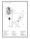
    10 key 1 - condensate trap 2 - gas valve 3 - gas inlet 4 - drain point 5 - ch fl ow 6 - diverter valve motor 7 - dhw outlet 8 - dhw sensor 9 - dhw flow detector 10 - dhw inlet 11 - safety pressure relief valve 12-water pressure transducer 13 - ch return 14 - control board 15 - circulation pump 16 - ...

  • Page 7

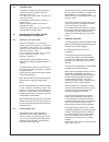
    11 key 1 - flue exhaust manifold 2 - condensate drain 3 - ch return 4 - ch return sensor 5 - heat exchanger 6 - ch fl ow 7 - overheat cut off thermostat 8 - ch fl ow sensor 9 - manual air vent 10 - burner 11 - spark electrode 12 - sensor electrode 13 - fan 14 - flue temperature temperature sensor 15...

  • Page 8

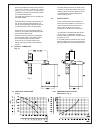
    As the heating sensor reaches temperature the fan speed modulates to maintain the temperature set on the display panel. When starting, the fan will always start at the set-point speed. The boiler is fi tted with an anti-cycling device on the control board. This delays the boiler from re-fi ring with...

  • Page 9

    13 when a hot water tap is turned on the diverter when a hot water tap is turned on the diverter valve motor moves to exclude the central valve motor moves to exclude the central heating circuit, the boiler automatically heating circuit, the boiler automatically modulates to maintain the domestic ho...