- DL manuals
- Suzuki
- Automobile
- Grand Vitara 1998
- Service Manual
Suzuki Grand Vitara 1998 Service Manual
Summary of Grand Vitara 1998
Page 1
Suzuki ──────────── sq 416-420-625 ──────────── m.Y 1998 - 2005 service manual volume 1 - chassis sections - electrical - body sections.
Page 2: Related Manual
Yh4 grand vol.1 related manual manual name manual no. Applicability sq416 / sq420 / sq625 unit repair manual 99501-65d01-xxx transmission, transfer and differentials (front and rear) of sq series. Sq416 / sq420 / sq625 wiring diagram manual 99512-65d10-015 applicable model mentioned in foreword of t...
Page 3
Yh4 grand vol.1 0a 0b 1a 1b 3 3a 3b1 3c 3c1 3d 3e 3f 4a2 4b 5 6 7a 5a 5b 5c 5e1 6a1 6a2 6a4 6b 6c 6e1 6e2 6f1 6f2 6g 6g1 6h 6k 7a1 7b1 7c1 7d 7e 7f 8 8b 8c 8d 8g 9 10 10a 8a 10b 6-1 engine general information and diagnosis (g16 / j20) general information and diagnosis (h25) engine mechanical (g16) e...
Page 4: Section 0A
Yh4 grand vitara 0a general information 0a-1 section 0a general information contents how to use this manual 0a- 2 . . . . . . . . . . . . . . . . . . . . . . . . . . . . . . . . . . . . . . . . . . . . . . . . . . . . . . . . . . . . . . . Precautions 0a- 3 . . . . . . . . . . . . . . . . . . . . . ...
Page 5: How To Use This Manual
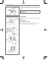
Yh4 grand vitara 6) install oil pump. Refer to “oil pump”. 7) install flywheel (for m/t vehicle) or drive plate (for a/t vehicle). Using special tool, lock flywheel or drive plate, and tighten flywheel or drive plate bolts to specified torque. Special tool (a): 09924-17810 tightening torque (c): 78 ...
Page 6: Precautions
Yh4 grand vitara 1. Air bag wire harness 2. Passenger air bag (inflator) module 3. Sdm 4. Dlc 5. Contact coil 6. Driver air bag (inflator) module 7. Seat belt pretensioner (if equipped) general information 0a-3 precautions precaution for vehicles equipped with a supplemental restraint (air bag) syst...
Page 7
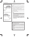
Yh4 grand vitara always carry air bag (inflator) module with trim cover (air bag opening) away from body. Always place air bag (inflator) module on workbench with trim cover (air bag opening) up, away from loose objects. 1. Slit on workbench 2. Workbench vise 3. Lower mounting bracket 0a-4 general i...
Page 8
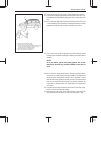
Yh4 grand vitara 1. Exhaust hole 1 1 ng general information 0a-5 warning: sdm during service procedures, be very careful when handling a sensing and diagnostic module (sdm). Never strike or jar the sdm. Never power up the air bag system when the sdm is not rigidly attached to the vehicle. All sdm an...
Page 9
Yh4 grand vitara 0a-6 general information caution: even when the accident was light enough not to cause air bags to activate, be sure to inspect system parts and other related parts according to instructions under “repair and inspection required after an accident” in section 10b. When servicing part...
Page 10
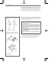
Yh4 grand vitara general information 0a-7 general precautions the warning and caution below describe some general precautions that you should observe when servicing a vehicle. These general precautions apply to many of the service procedures described in this manual, and they will not necessarily be...
Page 11
Yh4 grand vitara “a” 0a-8 general information when removing the battery, be sure to disconnect the nega- tive cable first and then the positive cable. When reconnect- ing the battery, connect the positive cable first and then the negative cable, and replace the terminal cover. When removing parts th...
Page 12
Yh4 grand vitara general information 0a-9 when disconnecting vacuum hoses, attach a tag describing the correct installation positions so that the hoses can be re- installed correctly. After servicing fuel, oil, coolant, vacuum, exhaust or brake systems, check all lines related to the system for leak...
Page 13
Yh4 grand vitara 1. Coupler 2. Probe 1. Coupler 2. Probe 3. Where male terminal fits 0a-10 general information precautions for electrical circuit service when disconnecting and connecting coupler, make sure to turn ignition switch off, or electronic parts may get dam- aged. Be careful not to touch t...
Page 14
Yh4 grand vitara general information 0a-11 when checking connection of terminals, check its male half for bend and female half for excessive opening and both for locking (looseness), corrosion, dust, etc. Before measuring voltage at each terminal, check to make sure that battery voltage is 11v or hi...
Page 15
Yh4 grand vitara 0a-12 general information 1. Check for loose connection sensor ecm check contact tension by inserting and removing just for once 1. Looseness of crimping 2. Open 3. Thin wire (single strand of wire) electrical circuit inspection procedure while there are various electrical circuit i...
Page 16
Yh4 grand vitara general information 0a-13 2v voltage drop continuity check 1) measure resistance between connector terminals at both ends of the circuit being checked (between a-1 and c-1 in the figure). If no continuity is indicated (infinity or over limit), that means that the circuit is open bet...
Page 17
Yh4 grand vitara 0a-14 general information to other parts other parts to other parts short circuit check (wire harness to ground) 1) disconnect negative cable from battery. 2) disconnect connectors at both ends of the circuit to be checked. Note: if the circuit to be checked is connected to other pa...
Page 18
Yh4 grand vitara 1. Check contact tension by inserting and removing just once. 2. Check each terminal for bend and proper alignment. General information 0a-15 intermittent and poor connection most intermittent are caused by faulty electrical connections or wir- ing, although a sticking relay or sole...
Page 19
Yh4 grand vitara 0a-16 general information poor terminal-to-wire connection. Check each wire harness in problem circuits for poor connection by shaking it by hand lightly. If any abnormal condition is found, repair or replace. Wire insulation which is rubbed through, causing an intermittent short as...
Page 20: Identification Information
Yh4 grand vitara g16 engine j20 engine h25 engine m / t (type1) 4-speed a / t m / t (type2) general information 0a-17 identification information body number the vehicle body number is on the left side of instrument panel and punched on the chassis inside the tire housing on the right front side. It ...
Page 21
Yh4 grand vitara note: air bag caution / warning labels are attached on the vehicle equipped with air bag system only. Engine cooling fan label radiator cap label air bag label emission control label (australia only) air bag label on sun visor transfer label 0a-18 general information warning, cautio...
Page 22: Vehicle Lifting Points
Yh4 grand vitara when using frame contact hoist: 1. Front lifting point 2. Rear lifting point 3. Front general information 0a-19 vehicle lifting points warning when using frame contact hoist, apply hoist as shown (right and left at the same position). Lift up the vehicle till 4 tires are a little of...
Page 23
Yh4 grand vitara 1. Front differential housing 2. Rear axle housing when using floor jack: front rear 1. Safety stands 0a-20 general information in raising front or rear vehicle end off the floor by jacking, be sure to put the jack against the center portion of the front suspension frame or rear axl...
Page 24
Yh4 grand vitara general information 0a-21 a abs : anti-lock brake system atdc : after top dead center api : american petroleum institute atf : automatic transmission fluid alr : automatic locking retractor ac : alternating current a / t : automatic transmission a / c : air conditioning abdc : after...
Page 25
Yh4 grand vitara l lh : left hand lspv : load sensing proportioning valve m maf sensor : mass air flow sensor (air flow sensor, afs, air flow meter, afm) map sensor : manifold absolute pressure sensor (pressure sensor, ps) max : maximum mfi : multiport fuel injection (multipoint fuel injection) min ...
Page 26: Metric Information
Yh4 grand vitara metric bolts–identification class numbers or marks correspond to bolt strength–increasing numbers represent increasing strength. Nut strength identification general information 0a-23 metric information metric fasteners most of the fasteners used for this vehicle are metric fasteners...
Page 27
Yh4 grand vitara 0a-24 general information self-lock nut standard tightening torque each fastener should be tightened to the torque specified in each section of this manual. If no description or specifi- cation is provided, refer to the following tightening torque chart for the applicable torque for...
Page 28: Section 0B
Yh4 grand vitara 0b maintenance and lubrication 0b-1 section 0b maintenance and lubrication warning: for vehicles equipped with supplemental restraint (air bag) system: service on and around the air bag system components or wiring must be performed only by an autho- rized suzuki dealer. Refer to “ai...
Page 29: Maintenance Schedule
Yh4 grand vitara 0b-2 maintenance and lubrication maintenance schedule maintenance schedule under normal driving conditions interval: this interval should be judged by this table includes services as scheduled up to 90,000 km (54,000 miles) mileage. Beyond 90,000 km (54,000 miles), carry out the sam...
Page 30
Yh4 grand vitara maintenance and lubrication 0b-3 interval: this interval should be judged by this table includes services as scheduled up to 90,000 km (54,000 miles) mileage. Beyond 90,000 km (54,000 miles), carry out the same services at the same intervals respectively. This interval should be jud...
Page 31
Yh4 grand vitara 0b-4 maintenance and lubrication maintenance recommended under severe driving conditions if the vehicle is usually used under the conditions corresponding to any severe condition code given below, it is recommended that applicable maintenance operation be performed at the particular...
Page 32: Maintenance Service
Yh4 grand vitara 1. Crankshaft pulley 2. Water pump pulley 3. 100 n, 10 kg or 22 lb g16 h25 maintenance and lubrication 0b-5 maintenance service engine item 1-1 drive belt inspection and replacement warning: all inspection and replacement are to be performed with engine not running. Water pump and g...
Page 33
Yh4 grand vitara j20 j20 1. 100 n, 10 kg or 22 lb 2. Fan pulley 3. Crankshaft pulley 4. Adjusting and pivot bolt 0b-6 maintenance and lubrication water pump, generator, power steering and / or a / c compressor (if equipped) drive belt (j20 engine) inspection 1) disconnect negative cable at battery. ...
Page 34
Yh4 grand vitara g16 with p / s g16 with p / s and a / c h25 with p / s h25 with p / s and a / c 1. Crankshaft pulley 2. P / s pump pulley 3. A / c compressor pulley (if equipped) 4. Tension pulley 5. Tension pulley bolts maintenance and lubrication 0b-7 power steering pump and / or a / c compressor...
Page 35
Yh4 grand vitara 0b-8 maintenance and lubrication item 1-2 camshaft timing belt replacement (g16 engine only) replace timing belt referring to section 6a1. Item 1-3 valve lash inspection (g16 engine only) 1) remove cylinder head cover. 2) inspect intake and exhaust valve lash and adjust as necessary...
Page 36
Yh4 grand vitara 2 1. Oil filter 2. Oil filter wrench maintenance and lubrication 0b-9 3) loosen oil filter by using oil filter wrench (special tool). Special tool (a): 09915-47310 (h25 engine) 09915-47330 (g16 and j20 engines) note: before fitting new oil filter, be sure to oil its o-ring. Use engi...
Page 37
Yh4 grand vitara 1. Full level mark (hole) 2. Low level mark (hole) 0b-10 maintenance and lubrication note: engine oil capacity is specified. However, note that the amount of oil required when actually changing oil may somewhat differ from the data in the table depending on various conditions (tempe...
Page 38
Yh4 grand vitara maintenance and lubrication 0b-11 1. Reservoir 2. Full level mark 3. Low level mark 4. Arrow mark 5. Reservoir cap 5 4 6) add coolant to reservoir so that its level aligns with full mark. Then, reinstall cap aligning arrow marks on reservoir and cap. Note: when installing reservoir ...
Page 39
Yh4 grand vitara 0b-12 maintenance and lubrication ignition system item 2-1 spark plugs replacement replace spark plugs with new ones referring to section 6f1 or 6f2. Fuel system item 3-1 air cleaner filter inspection 1) remove air cleaner case clamps. 2) take cleaner filter out of air cleaner case....
Page 40
Yh4 grand vitara maintenance and lubrication 0b-13 item 3-3 fuel filter replacement warning: this work must be performed in a well ventilated area and away from any open flames (such as gas hot water heaters). Fuel filter is located at the front part of fuel tank, inside the right- hand side of chas...
Page 41
Yh4 grand vitara [a] [b] [a]: type 1 [b]: type 2 0b-14 maintenance and lubrication emission control system item 4-1 crankcase ventilation hoses and connections inspection (vehicle not equipped with oxygen sensor) refer to the following item 4-2, pcv valve inspection. Item 4-2 pcv (positive crankcase...
Page 42
Yh4 grand vitara 1 1. Clutch pedal free travel maintenance and lubrication 0b-15 chassis and body item 6-1 clutch pedal inspection check clutch pedal for height and free travel referring to section 7c1. Adjust or correct if necessary. Fluid inspection 1) check around master cylinder and reservoir fo...
Page 43
Yh4 grand vitara “a”: parking brake lever stroke: 5 – 7 notches (with 20 kg or 44 lbs of pull pressure) “a” 0b-16 maintenance and lubrication item 6-3 brake hoses and pipes inspection check brake hoses and pipes for proper hookup, leaks, cracks, chafing and other damage. Replace any of these parts a...
Page 44
Yh4 grand vitara 1. Wear indicator maintenance and lubrication 0b-17 item 6-6 tire inspection and rotation 1) check tires for uneven or excessive wear, or damage. If defective, replace. Refer to section 3 for details. 2) check inflating pressure of each tire and adjust pressure to specification as n...
Page 45
Yh4 grand vitara 0b-18 maintenance and lubrication item 6-8 suspension system inspection check suspension bolts and nuts for tightness and retighten them as necessary. Repair or replace defective parts, if any. Note: for details of check points, refer to tables of tightening torque specification in ...
Page 46
Yh4 grand vitara maintenance and lubrication 0b-19 11) check coil spring, upper rod, lower rod and lateral rod for de- formation and damage. 12) check upper rod, lower rod and lateral rod bushings and bump stopper for wear, damage and deterioration. 13) check other suspension parts for damage, loose...
Page 47
Yh4 grand vitara 1. Drain plug (apply sealant) 2. Reverse idle gear shaft bolt (do not loosen it) 3. Filler / level plug (apply sealant) 1. Drain plug 2. Filler / level plug type 1 type 2 1. Level gauge 2. Full hot mark 3. Low hot mark 4. Full cold mark 5. Low cold mark 0b-20 maintenance and lubrica...
Page 48
Yh4 grand vitara 1. Drain plug transfer front differential rear differential 1 2 1 2 maintenance and lubrication 0b-21 change 1) inspect transmission case for evidence of fluid leakage. Repair leaky point, if any. 2) make sure that vehicle is placed level for fluid level check. 3) change fluid. For ...
Page 49
Yh4 grand vitara the figure shows right-hand steering vehicle the figure shows right-hand steering vehicle 0b-22 maintenance and lubrication item 6-14 steering system inspection 1) check steering wheel for play and rattle, holding vehicle in straight forward condition on the ground. Steering wheel p...
Page 50
Yh4 grand vitara 1. “upper” or “lower” mark maintenance and lubrication 0b-23 3) visually check pump drive belt for cracks and wear. 4) check belt for tension, referring to item 1-1. If necessary, have belt adjusted or replaced. Item 6-16 all hinges, latches and locks inspection doors check that eac...
Page 51
Yh4 grand vitara 0b-24 maintenance and lubrication final inspection seats check that seat slides smoothly and locks securely at any position. Also check that reclining mechanism of front seat back allows it to be locked at any angle. Seat belt inspect belt system including webbing, buckles, latch pl...
Page 52
Yh4 grand vitara maintenance and lubrication 0b-25 steering check to ensure that steering wheel is free from in- stability, or abnormally heavy feeling. Check that the vehicle does not wander or pull to one side. Engine check that engine responds readily at all speeds. Check that engine is free from...
Page 53: Section 1A
Yh4 grand vitara 1a heater and ventilation 1a-1 section 1a heater and ventilation warning: for vehicles equipped with supplement restraint (air bag) system service on and around the air bag system components or wiring must be performed only by an autho- rized suzuki dealer. Refer to “air bag system ...
Page 54: General Description
Yh4 grand vitara 1. Side ventilator outlet 2. Side defroster outlet 3. Center ventilator outlet 4. Heater unit 5. Defroster duct 6. Ventilator duct 7. Heater control lever assembly 8. Heater mode control switch 9. Blower unit 10. Rear duct 1a-2 heater and ventilation general description the heater, ...
Page 55: Diagnosis
Yh4 grand vitara heater and ventilation 1a-3 body ventilation the body ventilation system of this vehicle has a fresh air intake located at the cowl top panel. When fresh air intake control lever is at fresh air position, ventilating air is drawn into the interior from the cowl center garnish and dr...
Page 56
Yh4 grand vitara 1a-4 heater and ventilation for lh vehicle for rh vehicle 1. From ignition switch 1 2. From ignition switch 2 3. From blower fuse 4. Head light relay 5. To a / c controller 6. Blower motor relay 7. Blower motor switch 8. Blower resistor 9. Blower motor 10. To ecm 11. To illumination...
Page 57: On-Vehicle Service
Yh4 grand vitara heater and ventilation 1a-5 1. Blower unit 2. Blower motor resistor 3. Blower motor relay 4. Blower fan 5. Blower motor 3. Cover on-vehicle service blower unit removal 1) disconnect negative (–) cable at battery. 2) disable air bag system, if equipped. Refer to disabling air bag sys...
Page 58
Yh4 grand vitara 1a-6 heater and ventilation 6) remove cooling unit (if equipped). Refer to item cooling unit (evaporator) removal in section 1b. 7) disconnect fresh air control cable from blower motor case. 8) remove blower motor unit (1) by removing its fastening nuts (2). 9) disconnect blower mot...
Page 59
Yh4 grand vitara heater and ventilation 1a-7 1. Fastening nuts 1. Air flow blower motor removal 1) disconnect negative (–) cable at battery. 2) disable air bag system, if equipped. Refer to disabling air bag system in section 10b. 3) remove ecm with bracket from blower motor unit. 4) disconnect harn...
Page 60
Yh4 grand vitara 1a-8 heater and ventilation blower motor relay removal 1) disconnect negative (–) cable at battery. 2) disable air bag system, if equipped. Refer to disabling air bag system in section 10b. 3) open glove box, then remove screw. 4) remove glove box. 5) disconnect relay coupler. 6) re...
Page 61
Yh4 grand vitara heater and ventilation 1a-9 1. Lo 2. M1 3. M2 4. Hi blower motor resistor removal 1) disconnect negative (–) cable (2) at battery (1). 2) disable air bag system, if equipped. Refer to disabling air bag system in section 10b. 3) open glove box (1), then remove screw (2). 4) remove gl...
Page 62
Yh4 grand vitara 1a-10 heater and ventilation 2. Screws 1 2 heater mode control switch removal 1) disconnect negative (–) cable at battery. 2) if equipped with air bag system, disable air bag system. Refer to disabling air bag system in section 10b. 3) remove meter cluster hood (1) by removing its m...
Page 63
Yh4 grand vitara heater and ventilation 1a-11 1 1. Mode control switch coupler 7) disconnect heater blower motor switch connector (1). 8) remove mode control switch with heater control lever assem- bly from the removed hole in mentioned step (5). 9) pull off heater control lever knob. 10) remove hea...
Page 64
Yh4 grand vitara 1a-12 heater and ventilation 1. Temperature control lever 2. Fresh air control lever 1. Fresh air control cable 1. Heater unit 2. Control cable 1 2 installation 1) install in reverse order of removal procedure. 2) adjust cables as follows. (1) move control lever fully in arrow direc...
Page 65
Yh4 grand vitara heater and ventilation 1a-13 1. Lever for left hand steering vehicle for right hand steering vehicle 4) disconnect heater mode control actuator coupler (1). 5) disconnect heater mode control actuator rod (2) from heater unit. 6) remove heater mode control actuator from heater unit b...
Page 66
Yh4 grand vitara 1. Blower motor switch connector 1 1a-14 heater and ventilation heater control lever assembly removal 1) disconnect negative (–) cable at battery. 2) if equipped with air bag system, disable air bag system. Refer to disabling air bag system in section 10b. 3) remove mode control swi...
Page 67
Yh4 grand vitara heater and ventilation 1a-15 1. Heater unit 2. Blower unit 3. Fresh air control cable 4. Temperature control cable 5. Heater control lever assembly heater control cables removal 1) remove heater control lever assembly. Refer to heater control lever assembly in this sec- tion. 2) rem...
Page 68
Yh4 grand vitara 1a-16 heater and ventilation 1. Heater unit 2. Heater core 3. Damper 4. Heater mode control actuator 5. Heater mode control switch 6. Heater control lever assembly heater unit.
Page 69
Yh4 grand vitara heater and ventilation 1a-17 1. Dash panel (engine room) 2. Nuts removal warning: failure to follow the following procedure and warning may cause air bag deployment, personal injury, damage to parts, or air bag being unable to deploy. Never rest a steering column assembly on steerin...
Page 70
Yh4 grand vitara 1a-18 heater and ventilation 11) remove heater core pipe clamps (1) and grommet (2). 12) pull out heater core (1) from unit (2). Installation 1) install heater unit by reversing removal procedure, noting the following items. When installing each part, be careful not to catch any cab...
Page 71
Yh4 grand vitara heater and ventilation 1a-19 1. Heater unit 2. Rear duct 3. Sdm rear duct removal 1) disconnect negative (–) cable at battery. 2) remove front seat. 3) remove console box. 4) take off carpet till rear duct is totally exposed. 5) remove rear duct. Installation reverse removal sequenc...
Page 72: Section 1B
Yh4 grand vitara 1b air conditioning (optional) 1b-1 general description 1b- 3 . . . . . . . . . . . . . . Identification of refrigerating system 1b- 3 . . . . Refrigerant flow of air conditioning system 1b- 4 . . . . . . . . . . . . . . . . . . . . . . . . . . . . Major components and location 1b- ...
Page 73
Yh4 grand vitara 1b-2 air conditioning (optional) condenser dryer (receiver / dryer) 1b-36 . . . . . . Air filter element 1b-37 . . . . . . . . . . . . . . . . . . . . . Cooling unit (evaporator) 1b-39 . . . . . . . . . . . . . . Expansion valve 1b-42 . . . . . . . . . . . . . . . . . . . . . A / c ...
Page 74: General Description
Yh4 grand vitara 1. Compressor label 2. Service valve seiko seiki denso air conditioning (optional) 1b-3 general description the air conditioning system of this model differs by the country of origin (the production plant.). One is japan (iwata) produced, other one is canada (cami) produced. For the...
Page 75
Yh4 grand vitara 1. Compressor 2. Magnet clutch 3. Condenser assembly 4. Receiver / dryer 5. Dual pressure switch 6. Expansion valve 7. Evaporator : liquid : vapor : superheated vapor 1b-4 air conditioning (optional) refrigerant flow of air conditioning system.
Page 76
Yh4 grand vitara 1. Cooling unit 2. Compressor 3. Condenser assembly 4. Receiver / dryer 5. Discharge hose 6. Suction hose 7. Condenser outlet pipe 8. Liquid pipe 9. Expansion valve 10. Ventilation air 11. Foot air 12. Defroster air 13. Demister air 14. Fresh air 15. Recirculation air 16. Heater uni...
Page 77: Diagnosis
Yh4 grand vitara 1b-6 air conditioning (optional) diagnosis general condition possible cause correction cool air won’t come out (a / c system won’t operative) no refrigerant fuse blown a / c switch faulty blower motor switch faulty a / c thermistor faulty dual pressure switch faulty wiring or ground...
Page 78
Yh4 grand vitara air conditioning (optional) 1b-7 condition possible cause correction cool air does not come out or insufficient cooling (a / c system normal operative) compressor faulty air in a / c system air leaking from cooling unit or air duct heater and ventilation system faulty blower motor f...
Page 79
Yh4 grand vitara 1b-8 air conditioning (optional) diagnosis of abnormal noise there are various types of noise, ranging from those produced in the engine compartment to those from the pas- senger compartment, also from rumbling noises to whistling noises. Abnormal noise from compressor condition pos...
Page 80
Yh4 grand vitara air conditioning (optional) 1b-9 abnormal noise from crankshaft pulley condition possible cause correction a large rattling noise is heard at idle or sudden acceleration. Loosen pulley mounting bolt. Worn or broken bearings. Retighten bolt. Replace bearings. Abnormal noise from tens...
Page 81
Yh4 grand vitara 3. Bubbles 1b-10 air conditioning (optional) quickly checking of refrigerant charge (if equipped with sight glass) charge of refrigerant the following procedure can be used for quickly checking whether the a / c system has a proper charge of refrigerant or not. Run engine at fast id...
Page 82
Yh4 grand vitara air conditioning (optional) 1b-11 compression system diagnosis compressor troubles are mainly following three types: gas leakage, noise and insufficient pressure. Compressor gas leakages in most cases develop from the shaft seal. When detecting gas leakage, always use a leak tester....
Page 83
Yh4 grand vitara for cami production vehicle for iwata production vehicle 1b-12 air conditioning (optional) performance diagnosis 1) confirm that vehicle and environmental conditions are as fol- lows. D vehicle is not exposed to direct sun. D ambient temperature is within 15 _ c – 35 _ c (59 _ f – 9...
Page 84
Yh4 grand vitara air conditioning (optional) 1b-13 9) check for each pressure of low side and high side if it is within shaded range of graph. If each gauge reading is out of specified pressure, correct de- fective part referring to following test diagnosis table. Example: gauges should read as foll...
Page 85
Yh4 grand vitara 1b-14 air conditioning (optional) high pressure cauge low pressure gauge thermometer a t center duct insufficient cooling of condenser performance diagnosis table testing results possible cause remedy pressure high (“a” area of high side graph) d refrigerant overcharged d expansion ...
Page 86
Yh4 grand vitara air conditioning (optional) 1b-15 ambient temperature within 30 – 35 _ c (85 – 95 _ f) condition manifold gauge mpa (kg / cm 2 ) (psi) detail cause correction lo hi 0.23 – 0.35 (2.3 – 3.5) (33 – 50) 1.4 – 1.75 (14 – 17.5) (200 – 249) normal condition. —— —— negative pressure 0.5 – 0...
Page 87
Yh4 grand vitara 1. Blower motor main relay 2. Blower motor 3. Blower motor resistor 4. Blower motor switch 5. A / c controller 6. Ecm 7. Heater mode control switch 8. Evaporator temperature sensor 9. Refrigerant pressure switch 10. Compressor relay 11. Compressor 12. Condenser cooling fan relay 13....
Page 88
Yh4 grand vitara air conditioning (optional) 1b-17 1. Blower motor main relay 2. Blower motor 3. Blower motor resistor 4. Blower motor switch 5. A / c controller 6. Ecm 7. Heater mode control switch 8. Evaporator temperature sensor 9. Refrigerant pressure switch for rh vehicle 10. Compressor relay 1...
Page 89
Yh4 grand vitara fig. A fig. B fig. C c51-3-6 for g16 and j20 engines c51-3-25 for h25 engine 1b-18 air conditioning (optional) inspection of a/c controller and its circuits caution: a / c controller and ecm cannot be checked by itself. It is strictly prohibited to connect voltmeter or ohmmeter to a...
Page 90
Yh4 grand vitara system circuit a. To heater fuse b. To rear defogger fuse c. To ignition / meter fuse d. To a / c fuse e. Only lh vehicle 1. Blower motor relay 2. Blower motor 3. Blower motor switch 4. A / c switch 5. Deflloster position switch 6. Deflloster / foot position switch 7. Dual pressure ...
Page 91
Yh4 grand vitara 1b-20 air conditioning (optional) a/c controller voltage values table terminal wire circuit measurement ground normal value condition ac1-1 b / w controller main power supply ground to engine (fig. B) 10 – 14 volts ignition switch on with engine stopped ac1-2 b / y controller main g...
Page 92
Yh4 grand vitara air conditioning (optional) 1b-21 terminal wire circuit measurement ground normal value condition ac2-1 l / y sensor ground ground to body (fig. A) – 0.4 – 0 volt engine running 1.5 volts (3150 ) evaporator thermistor temperature at approx. 15 _ c (59 _ f) with engine running ac2-2 ...
Page 93
Yh4 grand vitara j20 engine h25 engine g16 engine 1. Generator belt 2. Compressor drive belt 3. Compressor pulley 4. Crankshaft pulley 1b-22 air conditioning (optional) drive belt inspection for g16 and h25 engines refer to section 3b1 for details. For j20 engine refer to section 6h for details..
Page 94
Yh4 grand vitara charge 440 50 g, 14.2 1.9 oz of refrigerant in gas form air conditioning (optional) 1b-23 refrigerant recovery, evacuation and charging warning: d your eyes should not be exposed to refrigerant (liquid). Any liquid refrigerant-134a escaping by accident shows a temperature as low as ...
Page 95
Yh4 grand vitara for cami production vehicle for iwata production vehicle 1b-24 air conditioning (optional) recovery note: when discharging refrigerant out of a / c system, always re- cover it by using refrigerant recovery and recycling equip- ment (1). Discharging it into atmosphere would cause ad-...
Page 96
Yh4 grand vitara for cami production vehicle for iwata production vehicle air conditioning (optional) 1b-25 evacuating evacuating procedure caution: do not evacuate before recovering refrigerant in system. Note: whenever opened (exposed to atmospheric air), air condition- ing system must be evacuate...
Page 97
Yh4 grand vitara for cami production vehicle for iwata production vehicle 1b-26 air conditioning (optional) charging caution: d always charge through low pressure-side of a / c system at after the initial charging is per- formed from the high-pressure side with the engine stopped. D never charge to ...
Page 98
Yh4 grand vitara 1. “hiss” air conditioning (optional) 1b-27 7) when refrigerant container (3) is emptied, use following proce- dure to replace it with a new refrigerant container (3). A. Close low pressure valve. B. Replace empty container (3) with a refrigerant container which has been charged wit...
Page 99
Yh4 grand vitara for cami production vehicle for iwata production vehicle 1b-28 air conditioning (optional) 8) after the system has been charged with specified amount of re- frigerant or when low pressure gauge (1) and high pressure gauge (2) have indicated about 2 and 15 kg / cm 2 respectively, clo...
Page 100
Yh4 grand vitara 1. Electric leak detector air conditioning (optional) 1b-29 removing manifold gauge set when a / c system has been charged with a specified amount of re- frigerant, remove manifold gauge set as follows: 1) close low pressure-side valve of manifold gauge set, (the high pressure-side ...
Page 101: On-Vehicle Service
Yh4 grand vitara 1. Suction hose 2. Discharge hose 3. Liquid pipe 4. Condenser outlet pipe 5. Expansion valve 6. Dual pressure switch 7. Suction pipe : apply compressor oil (refrigerant oil) to o-ring. 1b-30 air conditioning (optional) on-vehicle service warning: should refrigerant hfc-134a (r-134a)...
Page 102
Yh4 grand vitara air conditioning (optional) 1b-31 d tighten flared nuts to specified torque. Tightening torque (flared nut used for) 8 mm pipe: 13 n . M (1.3 kg-m, 9.5 lb-ft) 14.5 mm pipe: 23 n . M (2.3 kg-m, 16.6 lb-ft) 16 mm pipe: 33 n . M (3.3 kg-m, 23.8 lb-ft) d route drain hose so that drained...
Page 103
Yh4 grand vitara 1. New compressor 2. Removed compressor 3. Excess oil (a – b) 1b-32 air conditioning (optional) replenishing compressor oil when replacing air conditioning parts with new ones, it is necessary to replenish oil by the amount supposedly remaining in each part. When changing gas only w...
Page 104
Yh4 grand vitara 2. Bolt for cami production vehicle for iwata production vehicle air conditioning (optional) 1b-33 a/c condenser assembly inspection check a) condenser fins for blockage b) condenser fittings for leakage c) condenser fins for damage clogged condenser fins should be washed with water...
Page 105
Yh4 grand vitara 3 1b-34 air conditioning (optional) 5) disconnect coupler from dual pressure switch (1). 6) disconnect condenser outlet pipe (3). 7) disconnect condenser cooling fan motor coupler (2). 8) remove condenser with fan. Note: be careful not to damage fins of condenser and radiator. 9) re...
Page 106
Yh4 grand vitara 1. Air flow air conditioning (optional) 1b-35 condenser cooling fan assembly inspection remove condenser assembly (refer to “a / c condenser as- sembly removal” in this section). Check continuity between terminal to terminal as shown. If check results are continuity, proceed to next...
Page 107
Yh4 grand vitara 1 2 2. Condenser dryer section 1b-36 air conditioning (optional) condenser dryer (receiver/dryer) removal 1) remove a / c condenser assembly (1) from vehicle (refer to “a / c condenser assembly removal” in this section.). 2) remove the condenser dryer cap from condenser. 3) remove t...
Page 108
Yh4 grand vitara 1 for cami production vehicle for iwata production vehicle 1 air conditioning (optional) 1b-37 air filter element removal 1) disconnect negative (–) cable at battery. 2) for vehicle with air bag system, disable air bag system. Refer to “disabling air bag system” in section 10b. 3) p...
Page 109
Yh4 grand vitara 1 1. Ears 1. Air flow 1b-38 air conditioning (optional) clean blow off dust by compressed air from air outlet side of the filter ele- ment. Installation reverse removal procedure for installation noting the followings: install filter into cooling unit directing arrow mark on its end...
Page 110
Yh4 grand vitara air conditioning (optional) 1b-39 cooling unit (evaporator) removal 1) disconnect negative (–) cable at battery. 2) disable air bag system. Refer to “disabling air bag system” in section 10b. 3) recover refrigerant by using recovery and recycling equipment. Be sure to follow the ins...
Page 111
Yh4 grand vitara 1 1b-40 air conditioning (optional) 3) remove upper case (1) and remove evaporator (2) from lower case (3). 4) remove following components from evaporator. Expansion valve (5) thermistor (evaporator temperature sensor) (4) disassembly (for iwata production vehicle) 1) remove filter ...
Page 112
Yh4 grand vitara air conditioning (optional) 1b-41 inspection 1) check evaporator fins for blockage. If found clogged, use com- pressed air to clean the fins. Caution: do not use water for cleaning of evaporator. Be careful not to damage evaporator fins. If evaporator fin is bent, straighten it by u...
Page 113
Yh4 grand vitara 3. Pipe clamp 1b-42 air conditioning (optional) expansion valve inspection refer to “troubleshooting procedure using manifold gauge set” in this section. Removal 1) recover refrigerant by using recovery and recycling equipment. Be sure to follow the instruction manual for the equipm...
Page 114
Yh4 grand vitara 1. Evaporator thermistor temperature resistance ( ) air conditioning (optional) 1b-43 a/c evaporator thermistor (evaporator temperature sensor) a thermistor is a temperature sensor to sense the temperature of air discharged from evaporator. The electrical characteristic is shown in ...
Page 115
Yh4 grand vitara 1b-44 air conditioning (optional) refrigerant pipes and hoses inspection 1) use a leak tester to check hoses and pipes for any gas leakage. 2) check each hose or pipe clamp for tightness. Retighten or replace loose clamp as required, if any. Removal 1) recover refrigerant by using r...
Page 116
Yh4 grand vitara 1 1. Mode control switch coupler 2. A / c switch 3. Indicator lamp air conditioning (optional) 1b-45 a/c switch removal 1) disconnect negative (–) cable at battery. 2) if equipped with air bag system, disable air bag system. Refer to “disabling air bag system” in section 10b. 3) rem...
Page 117
Yh4 grand vitara 1b-46 air conditioning (optional) a/c controller removal 1) disconnect negative (–) cable at battery. 2) disable air bag system, if equipped. Refer to “disabling air bag system” in section 10b. 3) open glove box, then remove screw. 4) remove glove box. 5) disconnect a / c controller...
Page 118
Yh4 grand vitara pressure a b c d switch on (continuity) off (no continuity) air conditioning (optional) 1b-47 dual pressure switch inspection 1) check dual pressure switch (1) on liquid pipe for continuity at normal temperature (approx. 25 _ c (77 _ f)) when a / c system has a proper charge of refr...
Page 119
Yh4 grand vitara 3. Compressor and condenser cooling fan fuse 1b-48 air conditioning (optional) a/c compressor relay and a/c condenser cooling fan relay inspection 1) disconnect negative (–) cable at battery. 2) remove condenser cooling fan motor relay (2) and / or compres- sor relay (1) from vehicl...
Page 120
Yh4 grand vitara for cami production vehicle for iwata production vehicle 2. High pressure side (delivery side hose) 3. Lower pressure side (suction side pipe) air conditioning (optional) 1b-49 compressor assembly caution: none of refrigerant, compressor oil and component parts is interchangeable be...
Page 121
Yh4 grand vitara 1b-50 air conditioning (optional) removal 1) run engine at idle with a / c on for 10 minutes. 2) disconnect negative (–) cable at battery. 3) recover refrigerant from refrigeration system using recovery and recycling equipment. Note: the amount of compressor oil at removed must be m...
Page 122
Yh4 grand vitara air conditioning (optional) 1b-51 g16 engine j20 engine h25 engine 3. Compressor pulley 4. Crankshaft pulley installation for iwata production vehicle 1) pour new compressor oil. The amount must be the same with the amount measured in removal. Note: compressor assembly supplied from...
Page 123
Yh4 grand vitara 1b-52 air conditioning (optional) g16 engine j20 engine 3. Compressor pulley 4. Crankshaft pulley for cami production vehicle 1) pour new compressor oil. The amount must be the same with the amount measured in removal. Note: compressor assembly supplied from factory is filled up wit...
Page 124
Yh4 grand vitara air conditioning (optional) 1b-53 1. Clutch plate bolt 2. Clutch plate 3. Circlip 4. Clutch pulley 5. Shim 6. Clutch coil 7. Compressor 5 6 7 magnet clutch assembly (for denso) inspection d inspect clutch plate and clutch pulley for signs of oil. D check clutch pulley for noise and ...
Page 125
Yh4 grand vitara 1b-54 air conditioning (optional) 2 4) remove shims from shaft. 5) using special tool (c), remove circlip. Special tool (c): 09900-06107 6) remove clutch coil lead wire clamp screw, and remove clutch coil read wire ground terminal. 7) remove clutch pulley with puller (1) from compre...
Page 126
Yh4 grand vitara air conditioning (optional) 1b-55 1. Armature plate 4) clutch pulley (1). (1) set clutch pulley squarely over clutch pulley installation boss. (2) place special tool (d) onto clutch pulley bearing. Ensure that edge rests only on inner race of bearing. (3) install snap ring. Special ...
Page 127
Yh4 grand vitara 1b-56 air conditioning (optional) 1. Clutch plate bolt 2. Clutch plate 3. Circlip 4. Clutch pulley 5. Washer 6. Shim 7. Oil felt ring 8. Clutch coil 9. Lip type seal 10. Compressor front head 11. Compressor body component 12. O-ring 13. Compressor thermal switch 3. Washer (if equipp...
Page 128
Yh4 grand vitara air conditioning (optional) 1b-57 3) using special tool (b), remove clutch plate (1). Special tool (b): 09991-06030 4) disconnect clutch coil lead wire from compressor thermal switch led wire. 5) remove felt ring (if equipped) and shims from shaft. 6) using special tool (c), remove ...
Page 129
Yh4 grand vitara 3. Washer (if equipped) 1b-58 air conditioning (optional) 4) install clutch pulley (1). (1) set clutch pulley squarely over clutch pulley installation boss. (2) place special tool (d) onto clutch pulley bearing. Ensure that edge rests only on inner race of bearing. (3) install snap ...
Page 130
Yh4 grand vitara air conditioning (optional) 1b-59 push 3. Cylinder 4. Case 5. O-ring 2. Bearing puller lip type seal (for seiko seiki) removal 1) remove magnet clutch assembly, referring to “magnet clutch assembly” in this section. 2) remove compressor front head (1) mounting bolt (10 pcs.). 3) rem...
Page 131
Yh4 grand vitara 1b-60 air conditioning (optional) 1. Front head 2) coat special tool (f) surface with oil and place it on the shaft. Special tool (f): 09991-06040 3) install o-ring (2) to case. 4) apply compressor (refringent) oil to lip seal and o-ring. 5) install compressor front head (1). 6) tig...
Page 132: Required Service Material
Yh4 grand vitara air conditioning (optional) 1b-61 09900-06107 snap ring pliers (opening type) 09991-06010 magnet clutch pulley installer 09991-06020 armature plate spanner 09991-06030 armature plate remover 09991-06040 lip type seal protector 09991-06050 lip type seal installer required service mat...
Page 133: Section 3
Yh4 grand vitara 3 steering, suspension, wheels and tires 3-1 general diagnosis 3-1 . . . . . . . . . . . . . . . . . Diagnosis table 3-1 . . . . . . . . . . . . . . . . . . . . . . Tire diagnosis 3-6 . . . . . . . . . . . . . . . . . . . . . . Irregular and / or premature wear 3-6 . . . . . . . Wea...
Page 134
Yh4 grand vitara 3-2 steering, suspension, wheels and tires condition possible cause correction abnormal or excessive tire wear sagging or broken springs. Tire out of balance. Disturbed front end alignment. Faulty shock absorber. Hard driving. Overloaded vehicle. Tires not rotating. Worn or loose ro...
Page 135
Yh4 grand vitara steering, suspension, wheels and tires 3-3 condition possible cause correction too much play in steering wheel bearings worn. Loose steering gear case bolts. Rack and pinion not properly adjusted. (if equipped with manual steering gear case) worn steering shaft joints. Worn tie rod ...
Page 136
Yh4 grand vitara 3-4 steering, suspension, wheels and tires condition possible cause correction wander or poor steering stability mismatched or uneven tires. Loose ball joints and tie rod ends. Faulty shock absorbers / struts or mounting. Loose stabilizer bar. Broken or sagging springs. Rack and pin...
Page 137
Yh4 grand vitara steering, suspension, wheels and tires 3-5 condition possible cause correction body leans or sways in corners loose stabilizer bar. Faulty shock absorbers, struts or mounting. Broken or sagging springs. Overloaded. Tighten stabilizer bar bolts or replace bushes. Replace shock absorb...
Page 138: Tire Diagnosis
Yh4 grand vitara [a] [b] hard cornering under-inflation lack of rotation incorrect wheel alignment tire construction non-uniformity wheel heavy acceleration [a] [b] 3-6 steering, suspension, wheels and tires tire diagnosis irregular and/or premature wear irregular and premature wear has many possibl...
Page 139
Yh4 grand vitara inflate tires to recommended pressure road test vehicle on level uncrowned road in both directions switch front tires side to side and road test again leads in same direction lead corrected if roughness results, replace tires lead reverses direction put tires back in original positi...
Page 140: Vibration Diagnosis
Yh4 grand vitara 3-8 steering, suspension, wheels and tires radial tire lead “lead” is the deviation of the vehicle from a straight path on a level road with no pressure on the steering wheel. Lead is usually caused by: 1) incorrect alignment. 2) uneven brake adjustment. 3) tire construction. The wa...
Page 141
Yh4 grand vitara steering, suspension, wheels and tires 3-9 caused by smooth road suspension movement (loaded runout) tire out of round tire stiffness variation rim bent or out of round.
Page 142: Section 3A
Yh4 grand vitara 3a alignment service data (without load) toe-in (toe-in gauge measurement) “b” – “a”: 0 2 mm (0 0.08 in.) camber angle “c”: 0’ 1 caster: 2 40’ 1 *1. Forward *2. Body center [a] : top view [b] : front view 1. Center line of wheel front end alignment 3a-1 section 3a front end alignmen...
Page 143
Yh4 grand vitara 3a-2 front end alignment camber camber is the tilting of the front wheels from the vertical, as viewed from the front of the vehicle. When the wheels tilt outward at the top, the camber is positive. When the wheels tilt inward at the top, the camber is negative. The amount of tilt i...
Page 144
Yh4 grand vitara 1. Turning radius gauge 1 front end alignment 3a-3 steering angle when tie rod end was replaced, check toe and then also steering angle with turning radius gauges. If steering angle is not correct, check if right and left tie-rods are equal in length (“a” in left figure). Steering a...
Page 145: Section 3B1
Yh4 grand vitara 3b1 power steering (p / s) system 3b1-1 general description 3b1- 2 . . . . . . . . . . . . . . Power steering system 3b1- 2 . . . . . . . . . . . . . . . . . Steering gear box 3b1- 3 . . . . . . . . . . . . . . . . . . . . . . Power steering (p / s) pump 3b1- 4 . . . . . . . . . . ....
Page 146: General Description
Yh4 grand vitara 1. Power steering gear box 2. Power steering pump 3. P / s fluid reservoir 1. Power steering pump 2. Valve section 3. P / s fluid reservoir 4. Rack 5. Pinion 6. Cylinder 3b1-2 power steering (p / s) system general description power steering system the power steering (p / s) system i...
Page 147
Yh4 grand vitara 1. Pin 2. Stub shaft (rotor) 3. Torsion bar 4. Sleeve 5. Bearing 6. Pinion 7. Gear box 8. Rack 9. Ferrule 10. Valve case power steering (p / s) system 3b1-3 steering gear box the steering gear box consists of two sections: one including a cyl- inder and the other a valve. Main compo...
Page 148
Yh4 grand vitara 1. Suction connector 2. O-ring 3. Pressure switch 4. Flow control valve (relief valve) 5. Spring 6. Plug 7. Pump cover 8. Cam ring 9. Vane 10. Rotor 11. Snap ring 12. Side plate 13. Pulley (pump shaft) 14. Oil seal 15. Pump body 16. Flow control valve assembly 3b1-4 power steering (...
Page 149: Diagnosis
Yh4 grand vitara power steering (p / s) system 3b1-5 diagnosis general diagnosis table condition possible cause correction steering wheel feels heavy (at low speed) d fluid deteriorated, low viscosity, different type of fluid mixed d pipes or hoses deformed, air entering through joint d insufficient...
Page 150
Yh4 grand vitara 3b1-6 power steering (p / s) system condition possible cause correction vehicle pulls to one side during straight driving mismatched or uneven tire low or uneven tire inflation pressure brake dragging in one wheel front end alignment out of order rear end alignment out of order malf...
Page 151
Yh4 grand vitara power steering (p / s) system 3b1-7 steering wheel steering wheel play check check steering wheel for looseness or rattle by trying to move it in its shaft direction and lateral direction. If found defective, repair or replace. Check steering wheel for play, holding car in straight ...
Page 152
Yh4 grand vitara [d] [c] [a] 1. P / s pump pulley 2. A / c compressor pulley (if equipped) 3. Crankshaft pulley 4. Tension pulley 5. Tension pulley bolts [a]: g16 type engine with a / c [b]: g16 type engine without a / c [c]: h25 type engine with a / c [d]: h25 type engine without a / c [b] 3b1-8 po...
Page 153
Yh4 grand vitara power steering (p / s) system 3b1-9 idle up system idle up system check 1) warm up engine to normal operating temperature. 2) turn a / c switch off, if equipped. 3) turn steering wheel fully and check idle speed. Engine idle speed drops a little momentarily when steering wheel is tu...
Page 154
Yh4 grand vitara 1. P / s fluid reservoir 2. Attachment 3. Gasket 4. Union bolt 5. High pressure side 6. Low pressure side 1. P / s fluid reservoir 2. Gauge valve (open) 3. P / s pump 4. P / s gear box 5. High pressure side 6. Low pressure side 3b1-10 power steering (p / s) system hydraulic pressure...
Page 155
Yh4 grand vitara 1. P / s fluid reservoir 2. Gauge valve (shut) 3. Oil pressure gauge 4. P / s pump 5. P / s gear box 1. P / s fluid reservoir 2. Gauge valve (open) 3. Oil pressure gauge 4. P / s pump 5. P / s gear box power steering (p / s) system 3b1-11 5) check relief pressure increase engine spe...
Page 156
Yh4 grand vitara 3b1-12 power steering (p / s) system tie-rod end boot check check boot for crack and damage and if any, replace it with a new one. Air bleeding procedure 1) hoist the front end of vehicle and apply safety stands. 2) fill p / s fluid reservoir with fluid up to specified level. Note: ...
Page 157: On-Vehicle Service
Yh4 grand vitara 1. Tie-rod end 2. Knuckle 3. Nut 1. Tie-rod 2. Mark 3. Lock nut 4. Tie-rod end 1. Tie-rod end ball joint 1. Tie-rod 2. Mark 3. Lock nut 4. Tie rod end 5. Knuckle 6. Nut 6, (a) power steering (p / s) system 3b1-13 on-vehicle service tie-rod end removal 1) hoist vehicle and remove whe...
Page 158
Yh4 grand vitara 1. High pressure pipe 2. Union bolt 3. Low pressure hose 4. Steering lower shaft bolt 3b1-14 power steering (p / s) system 3) after installing wheels, lower vehicle and tighten wheel nuts to specified torque. Tightening torque (a): 100 n . M (10.0 kg-m, 72.5 lb-ft) 4) check that pro...
Page 159
Yh4 grand vitara 1. Steering gear box mounting bolts 1. Mark 2. Gear case 3. Pinion shaft power steering (p / s) system 3b1-15 7) remove steering gear box mounting bolts and then remove steering gear box from vehicle. Steering gear box found to be in defective condition should be replaced with a new...
Page 160
Yh4 grand vitara 3b1-16 power steering (p / s) system 1. Clip 2. Wire make marking here rack boot and tie-rod (except canvas top lh model) removal caution: never disassemble tie-rod except for canvas top lh model. Performing this prohibited service will affect original per- formance. 1) remove steer...
Page 161
Yh4 grand vitara power steering (p / s) system 3b1-17 1. Tie-rod 2. Steering rack 3. Boot 4. Mark 1. Tie-rod lock washer 2. Tie-rod 3. Steering rack 4. Aluminium plate 5. Vise 1. Tie-rod 2. Mark 3. Lock nut 4. Tie-rod end 5. Knuckle 6. Nut 2) install tie-rod end lock nut and tie-rod end to tie-rod. ...
Page 162
Yh4 grand vitara 3b1-18 power steering (p / s) system “a” 1 1 1. Mark 1. Tie-rod lock washer (a) installation 1) install new tie-rod lock washer and tie-rod to rack. 2) tighten tie-rod ball nut to specified torque. Tightening torque (a): 85 n . M (8.5 kg-m, 61.5 lb-ft) 3) bend lock washer 2 place at...
Page 163
Yh4 grand vitara power steering (p / s) system 3b1-19 tightening torque (a): 60 n . M (6.0 kg-m, 43.5 lb-ft) (b): 25 n . M (2.5 kg-m, 18.5 lb-ft) (c): 55 n . M (5.5 kg-m, 40.0 lb-ft) (d): 11 n . M (1.1 kg-m, 8.0 lb-ft) (e): 35 n . M (3.5 kg-m, 25.5 lb-ft) ( f ):40 n . M (4.0 kg-m, 29.0 lb-ft) (g): 4...
Page 164
Yh4 grand vitara 3b1-20 power steering (p / s) system 1. P/s fluid reservoir 2. Suction hose 1. P / s pulley 2. Mounting bolt 9. Vane 10. Rotor 11. Snap ring 12. Side plate 13. Pulley (pump shaft) 14. Oil seal 15. Pump body 16. Flow control valve assembly 1. Suction connector 2. O-ring 3. Pressure s...
Page 165
Yh4 grand vitara power steering (p / s) system 3b1-21 1. Thickness gauge inspection pump body, cover, side plate and shaft check sliding surfaces of each part for wear and damage. If any defect is found, replace pump assembly. Cam ring check vane sliding surface of cam ring for wear and damage. If a...
Page 166
Yh4 grand vitara 3b1-22 power steering (p / s) system 1. Flow control spring 1. Oil seal 2. Shaft (pulley) 1. O-ring 1. Side plate 2. Bolt hole 1. Rotor 2. Snap ring 3. Dot check free length of relief valve spring. Free length: standard 22.0 mm (0.866 in.) limit 19.0 mm (0.748 in.) replace if any de...
Page 167
Yh4 grand vitara power steering (p / s) system 3b1-23 1. Cam ring 2. Side plate 1. Rotor 2. Vane 1. O-ring 1. Dowel pin 2. Cover plate 7) apply power steering fluid to sliding surface of cam ring. 8) install cam ring to pump body. The tapered end of cam ring should face the side plate. 9) apply powe...
Page 168
Yh4 grand vitara 3b1-24 power steering (p / s) system 1. Pump cover 1. Pressure switch 1. Suction connector 2. O-ring 1. Suction connector 15) gradually tighten new pump cover bolts to specified torque. Note: after installing pump cover, check to make sure that shaft can be turned by hand. Tightenin...
Page 169
Yh4 grand vitara power steering (p / s) system 3b1-25 installation reverse removal procedure, and then noting the following instruc- tions. For tightening torques, refer to structural diagram on previous page. Adjust power steering pump drive belt by referring to “belt ten- sion adjustment” under “p...
Page 170: Required Service Material
Yh4 grand vitara 3b1-26 power steering (p / s) system 09915-77420 oil pressure gauge attachment and hose set 09915-77410 oil pressure gauge 09943-55010 boot clamp plier tightening torque specification fastening parts tightening torque fastening arts n . M kg-m lb-ft gear box mounting bolts 55 5.5 40...
Page 171: Section 3C
Yh4 grand vitara 3c steering wheel and column 3c-1 section 3c steering wheel and column (not equipped with air bag) note: all steering wheel and column fasteners are important parts in that they could affect the performance of vital parts and systems, and / or could result in major repair expense. T...
Page 172: Diagnosis
Yh4 grand vitara 1. Steering wheel pad 2. Steering wheel pad screw 3. Steering wheel nut 4. Steering wheel 5. Combination switch 6. Steering column upper cover 7. Steering column lower cover 8. Steering column assembly 9. Steering lock assembly 10. Steering column hole cover 11. Steering shaft joint...
Page 173: On-Vehicle Service
Yh4 grand vitara 1. Steering wheel 2. Steering wheel pad 3. Screw 1. Steering shaft nut 1. Steering wheel 1. Lugs 2. Grooves 3. Alignment marks steering wheel and column 3c-3 on-vehicle service steering wheel removal 1) disconnect negative battery cable at battery terminal. 2) remove steering wheel ...
Page 174
Yh4 grand vitara 1. Combination switch 1. Steering column hole cover : if equipped 2. Screw 1. Combination switch 2. Screw 1. Steering column cover screw 2. Steering column lower cover * 3. Steering column upper cover 3c-4 steering wheel and column combination switch removal 1) disconnect negative b...
Page 175
Yh4 grand vitara 1. Steering column hole cover 2. If equipped 1. Steering column cover screw 2. Steering column lower cover 3. Steering column upper cover : tapping screw : standard screw * * * steering wheel and column 3c-5 3) install steering column upper and lower cover. 4) tighten steering colum...
Page 176
Yh4 grand vitara 1. Steering column assembly 2. Steering shaft joint 3. Marks 1. Steering column assembly 2. Steering shaft joint 3. Steering lower shaft assembly 4. Bolt (column side) 5. Bolt (lower shaft assembly side) 1. Steering column hole cover : if equipped * 3c-6 steering wheel and column 2)...
Page 177
Yh4 grand vitara 1. Steering column 2. Steering column mounting bolt 3. Steering column lower seal 1. Shift (key) interlock cable 2. Screw 1. Capsule 2. Steering column bracket 3. Plate 1. Steering column assembly “a” steering wheel and column 3c-7 7) remove steering column mounting bolts (6 pieces)...
Page 178
Yh4 grand vitara 1. Steering column 2. Mounting bolt 3. Steering column lower seal 4. Dash panel 1. Steering column lower seal in engine room in cabin 3c-8 steering wheel and column 4) check steering column lower seal for breakage or deformation. If found defective, replace. 5) check steering shaft ...
Page 179
Yh4 grand vitara 1. Steering shaft joint 2. Steering shaft (column side) 3. Marks 1. Steering shaft joint 2. Bolt (column side) 3. Bolt (lower shaft assembly side) 1. Steering column hole cover : if equipped * steering wheel and column 3c-9 4) install steering shaft joint to steering shaft by matchi...
Page 180
Yh4 grand vitara 1. Steering column 2. Steering lock 1. Center punch (with sharp point) 2. Steering lock mounting bolt 1. Steering column 2. Steering shaft 3c-10 steering wheel and column steering lock assembly (ignition switch) removal 1) remove steering column. Refer to “steering column” in this s...
Page 181
Yh4 grand vitara 1. Steering column assembly 2. Steering shaft joint 3. Marks 1. Steering column assembly 2. Steering shaft joint 3. Steering lower shaft assembly 4. Bolt (column side) 5. Bolt (lower shaft assembly side) 1. Steering lower shaft assembly 2. Steering lower shaft assembly lower joint b...
Page 182
Yh4 grand vitara 1. Steering shaft joint 2. Bolt (steering column assembly side) 3. Bolt (lower steering shaft assembly side) 1. Steering column assembly 2. Steering shaft joint 3. Marks 1. Steering lower shaft assembly 2. Steering lower shaft assembly lower joint bolt 3. Steering shaft joint 1. Ste...
Page 183
Yh4 grand vitara steering wheel and column 3c-13 1. Capsule 2. Steering column bracket 3. Plate 1. Steering column assembly 1. Steering column lower seal “a” checking steering column for accident damage note: vehicles involved in accidents resulting in body damage, where steering column has been imp...
Page 184: Special Tool
Yh4 grand vitara 1. Lower position 2. Upper position 3c-14 steering wheel and column 09944-36011 steering wheel remover adjustable steering column release lever inspection check to make sure that the following: steering column moves smoothly when adjustable steering col- umn release lever is at lowe...
Page 185: Section 3C1
Yh4 grand vitara 3c1 air bag steering wheel and column 3c1-1 general description 3c1- 2 . . . . . . . . . . . . . Diagnosis 3c1- 3 . . . . . . . . . . . . . . . . . . . . . . . . . . Inspection and repair required after accident 3c1- 3 . . . . . . . . . . . . . . . . . . . . . . . . . . On-vehicle s...
Page 186: General Description
Yh4 grand vitara 14 15 1. Driver air bag (inflator) module 2. Steering wheel 3. Steering wheel nut 4. Contact coil and combination switch assembly 5. Steering column upper cover 6. Steering column lower cover 7. Steering column assembly 8. Steering lock assembly 9. Steering column hole cover 10. Ste...
Page 187: Diagnosis
Yh4 grand vitara air bag steering wheel and column 3c1-3 diagnosis for diagnosis of the steering wheel and steering column, refer to section 3. For diagnosis of the air bag system, refer to section 10b. Inspection and repair required after accident after an accident, whether the air bag has been dep...
Page 188
Yh4 grand vitara 1 1 1 1. Mounting bolt 1. Driver air bag (inflator) module connector 2. Horn connector 3. Driver air bag (inflator) module 4. Steering wheel 3c1-4 air bag steering wheel and column drive air bag (inflator) module warning: when handling an air bag (inflator) module, be sure to read “...
Page 189
Yh4 grand vitara 6, (a) 1. Trim cover (pad surface) 2. Inflator case 3. Wire harness 1. Driver air bag (inflator) module connector 2. Horn connector 3. Driver air bag (inflator) module 4. Steering wheel 5. Mounting bolt (left side) 6. Mounting bolt (right side) air bag steering wheel and column 3c1-...
Page 190
Yh4 grand vitara (a) 1 1. Make alignment marks 1. Steering wheel turn slowly till coil stops turn contact coil back about 2 and a half turns 1. Align marks 3c1-6 air bag steering wheel and column steering wheel caution: removal of the steering wheel allows the contact coil to turn freely but do not ...
Page 191
Yh4 grand vitara 1 1. Lugs 2. Grooves 3. Alignment marks 2. Steering column upper cover 3. Steering column lower cover 1. Steering column cover screw (a) 1. Steering column hole cover air bag steering wheel and column 3c1-7 installation 1) check that vehicle’s front tires are at straight-ahead posit...
Page 192
Yh4 grand vitara 1 1. Contact coil and combination switch assembly 2. Screw 1. Contact coil and combination switch assembly 1. Seal (if equipped, remove lock pin after installing contact coil and combination switch assembly.) 2. Lock pin (if equipped, remove lock pin after installing contact coil an...
Page 193
Yh4 grand vitara 1 1. Steering column hole cover 1. Steering column cover screw 2. Steering column upper cover 3. Steering column lower cover : standard screw : tapping screw * * * air bag steering wheel and column 3c1-9 3) connect all connectors that have been removed in removal. 4) install steerin...
Page 194
Yh4 grand vitara 1. Steering column assembly 2. Steering shaft joint 3. Marks 1. Steering column assembly 2. Steering shaft joint 3. Steering lower shaft assembly 4. Bolt (column side) 5. Bolt (lower shaft assembly side) 1. Steering column hole cover 1 3c1-10 air bag steering wheel and column remova...
Page 195
Yh4 grand vitara air bag steering wheel and column 3c1-11 1. Steering column 2. Steering column mounting bolt 3. Steering column lower seal 1. Shift (key) interlock cable 2. Screw 1. Capsule 2. Steering column bracket 3. Plate 1. Steering column assembly “a” 8) remove steering column mounting bolts ...
Page 196
Yh4 grand vitara 1. Steering column 2. Mounting bolt 3. Steering column lower seal 4. Dash panel 1. Steering column lower seal in engine room in cabin 1. Shift (key) interlock cable 2. Screw 3c1-12 air bag steering wheel and column 4) check steering column lower seal for breakage or deformation. If ...
Page 197
Yh4 grand vitara 1. Steering shaft joint 2. Steering shaft (column side) 3. Marks 1. Steering shaft joint 2. Bolt (column side) 3. Bolt (lower shaft assembly side) 1. Steering column hole cover 1 air bag steering wheel and column 3c1-13 4) install steering shaft joint to steering shaft by matching i...
Page 198
Yh4 grand vitara 3c1-14 air bag steering wheel and column 1. Steering column 2. Steering lock 1 2 1. Center punch (with sharp point) 2. Steering lock mounting bolt 1. Steering column 2. Steering shaft steering lock assembly (ignition switch) removal 1) remove steering column. Refer to “steering colu...
Page 199
Yh4 grand vitara air bag steering wheel and column 3c1-15 1. Steering column assembly 2. Steering shaft joint 1. Steering column assembly 2. Steering shaft joint 3. Steering lower shaft assembly 4. Bolt (column side) 5. Bolt (lower shaft assembly side) 1. Steering lower shaft assembly 2. Steering lo...
Page 200
Yh4 grand vitara 2 1 1. Steering shaft joint 2. Bolt (steering column assembly side) 3. Bolt (steering lower shaft assembly side) 1. Steering shaft joint 2. Steering lower shaft assembly 1. Steering lower shaft assembly 2. Steering lower shaft assembly lower joint 3. Steering lower shaft assembly lo...
Page 201
Yh4 grand vitara air bag steering wheel and column 3c1-17 1. Capsule 2. Steering column bracket 3. Plate 1. Steering column assembly 1. Steering column lower seal “a” checking steering column for accident damage note: vehicles involved in accidents resulting in body damage, where steering column has...
Page 202: Special Tool
Yh4 grand vitara 1. Lower position 2. Upper position 3c1-18 air bag steering wheel and column 09944-36011 steering wheel remover adjustable steering column release lever inspection check to make sure that the following: steering column moves smoothly when adjustable steering col- umn release lever i...
Page 203: Section 3D
Yh4 grand vitara 3d front suspension 3d-1 general description 3d- 2 . . . . . . . . . . . . . . Diagnosis 3d- 3 . . . . . . . . . . . . . . . . . . . . . . . . . . . Diagnosis table 3d- 3 . . . . . . . . . . . . . . . . . . . . . . Stabilizer bar and bushing check 3d- 3 . . . . . . Strut damper and ...
Page 204: General Description
Yh4 grand vitara 1. Body 2. Strut assembly 3. Steering knuckle 4. Suspension control arm (lower arm) 5. Ball stud 6. Wheel bearing 7. Axle shaft drive flange 8. Wheel 2wd 4wd 3d-2 front suspension general description the front suspension is the strut type independent suspension. The upper end of a s...
Page 205: Diagnosis
Yh4 grand vitara front suspension 3d-3 diagnosis diagnosis table refer to section 3. Stabilizer bar and bushing check bar inspect for damage or deformation. If defective, replace. Bushing inspect for damage, wear or deterioration. If defective, replace. Strut damper and/or coil spring check 1) inspe...
Page 206
Yh4 grand vitara 3d-4 front suspension suspension control arm joint check 1) check for smoothness of rotation. 2) inspect ball stud for damage. 3) inspect dust cover for damage. Replace any parts found defective in steps 1) – 3). Suspension control arm bushing check inspect for damage, wear or deter...
Page 207: On-Vehicle Service
Yh4 grand vitara front suspension 3d-5 1. Suspension control arm 2. Stabilizer bar 3. Stabilizer ball joint 4. Ball joint bushings 5. Ball joint washers 6. Ball joint nuts 7. Bracket bolts 1. Painted 2. Mount bush bracket 3. Mount bush on-vehicle service stabilizer bar/bushings removal 1) hoist vehi...
Page 208
Yh4 grand vitara 3d-6 front suspension 1. Strut tower bar 1. E-ring 1. Front wheel speed sensor harness clamp bolt 1. Strut bracket bolts 2. Lower arm 3. Jack 1. Strut support nuts strut damper removal 1) remove strut tower bar (if equipped). 2) hoist vehicle, allowing front suspension to hang free....
Page 209
Yh4 grand vitara front suspension 3d-7 1. E-ring 2. Bracket end surface installation 1) install strut by reversing removal steps 1) – 8). Insert bolts in such a direction as shown. 2) torque all fasteners to specifications. Tightening torque (a): 55 n . M (5.5 kg-m, 40.0 lb-ft) (b): 95 n . M (9.5 kg...
Page 210
Yh4 grand vitara 3d-8 front suspension 1. Circlip 2. Washer 1. Wire 1. Front wheel speed sensor 2. Harness clamp bolt coil spring removal 1) hoist vehicle, allowing front suspension to hang free. 2) remove wheels. 3) remove axle shaft drive flange (for 4wd vehicle). 4) remove front drive shaft circl...
Page 211
Yh4 grand vitara front suspension 3d-9 1. Coil spring 8) remove stabilizer bar, refer to steps 2) to 5) of item stabiliz- er bar / bushings removal in this section. 9) disconnect tie rod end from knuckle by using puller. 10) support lower arm, using jack as shown. 11) remove strut bracket bolts. 12)...
Page 212
Yh4 grand vitara 3d-10 front suspension “a” 1. Circlip 2. Large diameter 1. Axle shaft drive flange 2. Bolt 1. Spring seat bottom installation reverse removal procedure to install coil spring. Note: upper and lower diameters of coil spring are different. Bring larger diameter end at bottom and set i...
Page 213
Yh4 grand vitara front suspension 3d-11 1. Front wheel speed sensor 2. Bolt 1. Spring rubber seat 2. Bump stopper 2, (b) 1 check that no foreign material is attached to sensor and rotor. Install wheel speed sensor and its harness clamp. Tightening torque (a): 10 n . M (1.0 kg-m, 7.5 lb-ft) (b): 23 n...
Page 214
Yh4 grand vitara 3d-12 front suspension 1. Lock washer 2. Screws 1. Axle shaft drive flange wheel hub (included wheel bearing) removal 1) hoist vehicle and remove wheel. 2) remove axle shaft drive flange (4wd vehicle) or hub cap (2wd vehicle). 3) if equipped with abs, remove wheel speed sensor from ...
Page 215
Yh4 grand vitara 1. Sensor rotor 2. Wheel hub 3. Vise 4. Flat end rod 1. Bearing lock washer 2. Screw 3. Bearing lock nut 4. Wheel bearing washer 5. Wheel hub component 6. Bolt 1. Oil hydraulic press 2. Hub bolt front suspension 3d-13 note: if wheel hub can not be removed by hand, use special tools ...
Page 216
Yh4 grand vitara 1. Wheel hub 2. Wheel spindle 3. Bearing inner race 1. Lock washer 1. Sensor rotor 2. Wheel hub 3. Hydraulic press ok ng 3d-14 front suspension 2) install new sensor rotor by using special tool (if equipped with abs). Note: use care not to insert wheel hub diagonally. Special tool (...
Page 217
Yh4 grand vitara 2, (b) 1 1. Circlip 2. Large diameter 1. Front wheel speed sensor 2. Bolt front suspension 3d-15 7) for 4wd vehicle, apply lithium grease to front drive shaft wash- er and front wheel spindle outer. “a”: grease 99000-25010 8) for 4wd vehicle, when installing circlip to drive shaft, ...
Page 218
Yh4 grand vitara 1. Axle shaft drive flange 2. Bolt 3. Hub cap 4. Wheel hub for 4wd vehicle for 2wd vehicle 3d-16 front suspension 11) apply sealant and install axle shaft drive flange or hub cap. For 4wd vehicle apply sealant mating surface of axle shaft drive flange, then install axle shaft drive ...
Page 219
Yh4 grand vitara 1. Drive shaft circlip 2. Spindle thrust washer 3. Drive shaft 4. Wheel spindle 1. Tie-rod end 2. Knuckle 1. Strut 2. Knuckle 1. Dust cover 2. Wheel spindle 3. Knuckle 4. Inner oil seal / knuckle cap front suspension 3d-17 knuckle/wheel spindle removal 1) remove wheel hub. Refer to ...
Page 220
Yh4 grand vitara “a” “b” 1. Wheel spindle 2. Drive shaft bearing 1. Wheel spindle 2. Drive shaft bearing 3. Front drive shaft thrust washer 4. Inner oil seal 5. Knuckle cap 6. Drive shaft oil seal type a type b 1. Drive shaft bearing 2. Wheel spindle 3d-18 front suspension 11) for 4wd vehicle remove...
Page 221
Yh4 grand vitara front suspension 3d-19 1. Knuckle 2. Knuckle cap 3. Wheel spindle 1. Oil seal 2. Drive shaft 3. Drive shaft thrust washer type a type b tighten wheel spindle nut to specified torque. Tightening torque (a): 50 n . M (5.0 kg-m, 36.5 lb-ft) for 4wd vehicle press-fitting inner oil seal....
Page 222
Yh4 grand vitara (a) 1. Axle shaft drive flange 2. Bolt 1. Hub cap 2. Wheel hub 3d-20 front suspension tighten control arm ball stud nut when tightening ball stud nut, use new nut and tighten it to speci- fied torque. Tightening torque (a): 60 n . M (6.0 kg-m, 43.5 lb-ft) for 2wd vehicle apply water...
Page 223
Yh4 grand vitara front suspension 3d-21 (1) (2) (a) 1. Hydraulic press 1. Hydraulic press cut off flange bush outer diameter suspension control arm/bushings removal 1) remove coil spring. Refer to coil spring in this section. 2) remove control arm bolts and nuts. Then remove control arm. 3) cut flan...
Page 224
Yh4 grand vitara 3d-22 front suspension 1. Hydraulic press 2. Front bushing a: bushing flange contacts housing edge 1. Hydraulic press 2. Rear bushing a: bushing flange contacts housing edge installation 1) front bushing press-fit front bushing until its flange contacts housing edge of control arm, ...
Page 225
Yh4 grand vitara front suspension 3d-23 tightening torque specifications.
Page 226: Required Service Materials
Yh4 grand vitara 3d-24 front suspension required service materials materials recommended suzuki product use no. Lithium grease suzuki super grease (a) (99000-25010) bearing inner oil seal / drive shaft oil seal recess of wheel spindles spindle outer washer spindle part of drive shaft spindle bush (i...
Page 227: Special Tools
Yh4 grand vitara front suspension 3d-25 09923-74510 bearing remover 09930-30102 sliding shaft 09924-74510 bearing installer handle 09941-66010 bump stopper wrench 09942-15510 sliding hammer 09943-35512 brake drum remover 09944-68210 bearing & oil seal installer 09944-66010 wheel hub / knuckle oil se...
Page 228: Section 3E
Yh4 grand vitara 3e rear suspension 3e-1 general description 3e- 2 . . . . . . . . . . . . . . Diagnosis 3e- 3 . . . . . . . . . . . . . . . . . . . . . . . . . . . Diagnosis table 3e- 3 . . . . . . . . . . . . . . . . . . . . . . Shock absorber check 3e- 3 . . . . . . . . . . . . . . . . Lower / up...
Page 229: General Description
Yh4 grand vitara 1. Rear axle housing 2. Coil spring 3. Axle shaft 4. Shock absorber 5. Upper rod 6. Lower rod 7. Oil level plug 8. Wheel bearing retainer 9. Rear wheel bearing 10. Brake back plate 11. Oil drain plug 12. Lateral rod note: when installing differential gear oil drain plug, clean the t...
Page 230: Diagnosis
Yh4 grand vitara “a”: drill hole with approximately 3 mm (0.12 in.) diameter. Rear suspension 3e-3 diagnosis diagnosis table refer to section 3. Shock absorber check inspect for deformation or damage. Inspect bushings for wear or damage. Inspect for evidence of oil leakage. Replace any defective par...
Page 231
Yh4 grand vitara 3e-4 rear suspension rear suspension fasteners check each bolt and nut fastening suspension parts for tightness. Tighten loose one, if any, to specified torque, referring to “tight- ening torque specifications” of this section. Bearing retainer and axle shaft inner oil seal check wh...
Page 232: On-Vehicle Service
Yh4 grand vitara 1. Rear axle housing 2. Floor jack 1. Lock nut (if equipped) 2. Absorber nut 3. Upper support 4. Rubber bush 5. Lower support 6. Shock absorber 7. Bolt upper side lower side 1. Lock nut (if equipped) 2. Absorber nut 3. Body outside rear suspension 3e-5 on-vehicle service shock absor...
Page 233
Yh4 grand vitara 1. Parking brake cable hanger 2. Cross member 3. Clamp 4. Chassis frame 1. Rear axle housing 2. Floor jack 1. Shock absorber 2. Lower bolt 1. Clamp 2. Upper rod 3e-6 rear suspension coil spring removal 1) hoist vehicle and remove rear wheel. 2) support rear axle housing by using flo...
Page 234
Yh4 grand vitara 1. Rear axle housing 2. Spring seat 3. Coil spring 4. Stepped part 1. Body center 2. Body outside 1. Body center 2. Body outside 1. Parking brake cable hanger 2. Cross member 3. Clamp 4. Chassis frame rear suspension 3e-7 installation 1) install coil spring on spring seat of axle ho...
Page 235
Yh4 grand vitara 1. Axle housing 2. Floor jack 1. Lower rod 2. Rear mount nut 1. Lower rod 2. Front mount bolt 1. Lower rod 2. Front bolt 3. Rear bolt 4. Vehicle body 5. Axle housing 6. Body center 7. Body out side [a]: body side [b]: axle side 3e-8 rear suspension lower rod removal 1) hoist vehicle...
Page 236
Yh4 grand vitara 1. Clamp 2. Upper rod 1. Upper rod front bolt 2. Nut 3. Upper rod 4. Wheel speed sensor harness bracket (toward outside of body) 1. Upper rod 2. Bolt 5. Upper rod rear bolt 6. Washer 7. Body center 8. Front side rear suspension 3e-9 upper rod removal 1) hoist vehicle and remove rear...
Page 237
Yh4 grand vitara (a) (a) 1. Bolt 2. Washer 3. Lateral rod 1. Nut 1 3e-10 rear suspension lateral rod removal 1) hoist vehicle. 2) remove lateral rod mounting bolts. 3) remove lateral rod. Installation 1) install lateral rod to rear axle, and vehicle body. 2) lower hoist. 3) tighten lateral rod mount...
Page 238
Yh4 grand vitara 1. Bearing retainer 2. Parking brake shoe lever 3. Clearance 1. Wheel speed sensor 1 l rear suspension 3e-11 4) remove wheel speed sensor from rear axle housing (if equipped with abs). Caution: do not pull wire harness or twist more than necessary when removing rear wheel speed sens...
Page 239
Yh4 grand vitara 1. Axle shaft 2. Wheel bearing 3. Press 1. Stud bolt 2. Hydraulic press 1. Rear wheel bearing retainer ring 2. Grind with a grinder 3. Rear axle 3e-12 rear suspension 9) break with a chisel the thin ground sensor rotor, and it can be removed (if equipped with abs). 10) in order to r...
Page 240
Yh4 grand vitara [b] 1 2 [a] 1. Bearing retainer 2. Oil seal 3. Wheel side 4. Differential side 1. Stud bolt 2. Nut 3. Washer 4. Flange of axle shaft 1. Axle shaft 2. Bearing retainer [a]: vehicle without abs [b]: vehicle with abs 1. Bearing 2. Retainer ring rear suspension 3e-13 installation instal...
Page 241
Yh4 grand vitara 1. Sensor rotor 1. Axle housing 1. Bearing retainer (b) 3e-14 rear suspension 5) for vehicle with abs, press-fit new sensor rotor as shown. Note: use care not to cause any damage to outside of retainer ring. 6) apply grease to axle shaft inner oil seal lip as shown. “a”: grease 9900...
Page 242
Yh4 grand vitara rear suspension 3e-15 1. Inner oil seal 2. Axle housing 1. Hammer 2. Screwdriver 3. Oil seal protector 4. Oil seal 5. Body center rear axle shaft inner oil seal removal 1) remove rear axle shaft. For details, refer to steps 1) to 7) of rear axle shaft removal in this section. 2) fix...
Page 243
Yh4 grand vitara 1. Brake pipe flare nut 2. Brake pipe 3. Brake back plate 1. Bearing retainer 2. Parking brake shoe lever 3. Clearance 1. Nut 1. Wheel speed sensor 2. Wheel speed sensor coupler 3. Wheel speed sensor harness clamp 4. Wheel speed sensor harness 3e-16 rear suspension rear axle housing...
Page 244
Yh4 grand vitara 1. Flexible hose 2. E-ring 3. Brake pipe 4. Cross member 1. Lspv stay 1. Hose 2. Axle housing 1. Propeller shaft 2. Differential carrier rear suspension 3e-17 7) using special tools (b) & (c) indicated below, draw out axle shafts. For vehicle equipped with abs, remove wheel speed se...
Page 245
Yh4 grand vitara 3e-18 rear suspension 1. Axle housing 2. Jack 1. Differential carrier assembly 2. Differential carrier nut 1. Lower rod 2. Lower rod rear mount nut 3. Shock absorber 1. Lower mount bolt 13) for jobs hereafter, support rear axle housing by using floor jack under axle housing. 14) rem...
Page 246
Yh4 grand vitara 1. Lower rod 2. Body center 1. Rear axle housing 2. Spring seat 3. Coil spring 4. Stepped part 1. Axle housing “a” 1. Body center 1 2 1 rear suspension 3e-19 installation install removed parts in reverse order of removal, noting the follow- ing. 1) place rear axle housing on floor j...
Page 247
Yh4 grand vitara 1. Axle housing “a” (c) 1. Axle housing 3e-20 rear suspension 7) for vehicle with abs, connect wheel speed sensor coupler and install harness. 8) install propeller shaft and torque nuts to specification. Tightening torque (b): 50 n . M (5.0 kg-m, 36.5 lb-ft) 9) remove floor jack fro...
Page 248
Yh4 grand vitara 3. Container 1. Plug cap 2. Vinyl tube 1. Bearing retainer (e) (f) (g) rear suspension 3e-21 16) apply sealant to mating surface of bearing retainer with brake back plate. Note: make sure to remove old sealant before applying it anew. “b”: sealant 99000-31110 17) install rear axle s...
Page 249
Yh4 grand vitara 3e-22 rear suspension 23) install wheel and tighten wheel nuts to specified torque. Tightening torque (h): 100 n . M (10.0 kg-m, 72.5 lb-ft) 24) upon completion of all jobs, depress brake pedal with about 30 kg (66 lbs) load three to ten times so as to obtain proper drum- to-shoe cl...
Page 250: Required Service Materials
Yh4 grand vitara rear suspension 3e-23 tightening torque specifications fastening parts tightening torque fastening arts n . M kg-m lb-ft shock absorber lock nut 29 2.9 21.0 shock absorber nut 29 2.9 21.0 shock absorber lower nut 85 8.5 61.5 lower rod bolt and nut upper rod bolt and nut 90 9.0 65.0 ...
Page 251: Special Tools
Yh4 grand vitara 3e-24 rear suspension 09924-74510 bush remover handle 09926-88310 oil seal installer 09942-15510 sliding hammer 09943-35512 brake drum remover 09913-75510 oil seal installer special tools.
Page 252: Section 3F
Yh4 grand vitara 3f wheels and tires 3f-1 general description 3f- 1 . . . . . . . . . . . . . . Tires 3f- 1 . . . . . . . . . . . . . . . . . . . . . . . . . . . . . . . . Wheels 3f- 1 . . . . . . . . . . . . . . . . . . . . . . . . . . . . . Replacement tires 3f- 1 . . . . . . . . . . . . . . . . ....
Page 253
Yh4 grand vitara 3f-2 wheels and tires the metric term for tire inflation pressure is the kilopascal (kpa). Tire pressures will usually be printed in both kpa and psi on the tire placard. Metric tire gauges are available from tool suppliers. The chart, left table, converts commonly used inflation pr...
Page 254: Diagnosis
Yh4 grand vitara [a]: before correction [b]: corrective weights 1. Heavy spot wheel tramp 2. Balance weights addition point 3. C / l of spindle [c]: before correction [d]: corrective weights 1. Heavy spot wheel shimmy 2. Balance weights addition point 3. C / l of spindle wheels and tires 3f-3 diagno...
Page 255
Yh4 grand vitara 1. Paint 3f-4 wheels and tires higher than recommended pressure can cause: 1. Hard ride 2. Tire bruising or carcass damage 3. Rapid tread wear at center of tire unequal pressure on same axle can cause: 1. Uneven braking 2. Steering lead 3. Reduced handling 4. Swerve on acceleration ...
Page 256
Yh4 grand vitara 1. Front wheels and tires 3f-5 tire placard the tire placard is located on the driver’s side door lock pillar and should be referred to for tire information. The placard lists the maxi- mum load, tire size and cold tire pressure where applicable. Tire rotation to equalize wear, rota...
Page 257: On-Vehicle Service
Yh4 grand vitara 3f-6 wheels and tires on-vehicle service wheel removal 1) loosen wheel nuts by approximately 180 (half a rotation). 2) hoist vehicle. 3) remove wheel. Note: never use heat to loosen tight wheel because application of heat to wheel can shorten life of wheel and damage wheel bearings....
Page 258
Yh4 grand vitara wheels and tires 3f-7 tire mounting and demounting use tire changing machine to mount or demount tires. Follow equip- ment manufacturer’s instructions. Do not use hand tools or tire irons alone to change tires as they may damage tire beads or wheel rim. Rim bead seats should be clea...
Page 259: Tightening Torque
Yh4 grand vitara 3f-8 wheels and tires tightening torque specifications tightening torque for wheel nut (a): 100 n . M (10.0 kg-m, 72.5 lb-ft).
Page 260: Section 4A2
Yh4 grand vitara 4a2 1. Drive shaft oil seal 2. Double off set joint (doj) 3. Joint circlip 4. Doj boot 5. Ball joint boot 6. Ball joint assembly (rh side) 7. Drive shaft assembly (lh side) 8. Left drive shaft 9. Drive shaft bearing circlip 10. Drive shaft bearing front drive shaft / shaft bearing, ...
Page 261: Diagnosis
Yh4 grand vitara 4a2-2 front drive shaft / shaft bearing, oil seal diagnosis diagnosis table condition possible cause correction when starting: abnormal noise loose wheel nuts. Loose drive shaft flange bolts. Broken or otherwise damaged wheel bearing. Tighten wheel nuts. Tighten drive shaft flange b...
Page 262: On-Vehicle Service
Yh4 grand vitara 1. Oil filler / level plug 2. Front drain plug 1. Circlip 2. Washer 1. Drive shaft flange bolts and nuts 1. Oil seal front drive shaft / shaft bearing, oil seal 4a2-3 on-vehicle service drive shaft removal (left side) 1) hoist vehicle and remove wheel. 2) remove axle shaft drive fla...
Page 263
Yh4 grand vitara 1. Oil filler / level plug 2. Front drain plug 1. Circlip 2. Washer 1. Differential side joint 2. Tire lever 3. Front differential assembly 1. Oil seal 2 1 4a2-4 front drive shaft / shaft bearing, oil seal removal (right side) 1) hoist vehicle and remove wheel. 2) drain differential...
Page 264
Yh4 grand vitara 1. Boot 2. Snap ring 1. Circlip 2 snap ring plier 3. Cage front drive shaft / shaft bearing, oil seal 4a2-5 disassembly 1) remove boot band of differential side joint. 2) slide boot toward the center of shaft and remove snap ring from outer race, then take shaft out of outer race. 3...
Page 265
Yh4 grand vitara 1. Boot 2. Boot band 1. Circlip 1. Cage wheel side “a” fill grease 85g (3.0 oz) 4a2-6 front drive shaft / shaft bearing, oil seal assembly caution: to prevent any problem caused by washing solution, do not wash joint boots. Degreasing of those parts with cloth is allowed. For m / t ...
Page 266
Yh4 grand vitara “a”: fill grease 90 – 95 g (3.2 – 3.4 oz) 1. Circlip [lh] [rh] differential side front drive shaft / shaft bearing, oil seal 4a2-7 7) apply grease to entire surface of cage. Use joint grease in tube included in spare part or joint grease (99000-25120). 8) insert cage into outer race...
Page 267
Yh4 grand vitara 1. Drive shaft oil seal 1. Drive shaft flange bolt and nut 2. Front spindle thrust washer 3. Axle shaft drive flange “a” 1. Drive shaft joint 2. Oil seal 3. Pipe 4. Thrust washer 4 4a2-8 front drive shaft / shaft bearing, oil seal installation install drive shaft assembly by reversi...
Page 268
Yh4 grand vitara 1. Left drive shaft 2. Tire lever 1. Shaft bearing 1. Axle oil seal 2. Circlip 3. Axle bearing front drive shaft / shaft bearing, oil seal 4a2-9 shaft bearing/oil seal removal 1) remove drive shaft assembly. Refer to item drive shaft removal (left and right) in this section. For rig...
Page 269
Yh4 grand vitara “a” 1. Shaft bearing 1. Shaft oil seal 2. Right side 3. Left side 4a2-10 front drive shaft / shaft bearing, oil seal installation 1) clean drive shaft oil seal and then apply lithium grease. “a”: grease 99000-25010 check oil seal for breakage or deterioration. Replace it as necessar...
Page 270: Required Service Materials
Yh4 grand vitara front drive shaft / shaft bearing, oil seal 4a2-11 09913-75520 bearing installer 09924-74510 installer attachment 09930-30102 sliding shaft 09941-64510 bearing remover 09951-16090 oil seal installer tightening torque specifications fastening parts tightening torque fastening arts n ...
Page 271: Section 4B
Yh4 grand vitara 4b 1. Front propeller shaft (if equipped) 2. Rear propeller shaft propeller shafts 4b-1 section 4b propeller shafts note: all propeller shaft fasteners are an important attaching part in that it could affect the performance of vital parts and systems, and / or could result in major ...
Page 272: Diagnosis
Yh4 grand vitara 4b-2 propeller shafts diagnosis diagnosis table condition possible cause correction abnormal noise loose universal joint bolt. Spider bearing worn out or stuck. Wear spider. Tighten universal joint bolt. Replace. Replace propeller shaft. Vibration deformed propeller shaft. Replace. ...
Page 273: On-Vehicle Service
Yh4 grand vitara 1. Match mark propeller shafts 4b-3 on-vehicle service propeller shaft removal 1) hoist vehicle. 2) drain transfer oil only when servicing front propeller shaft. 3) before removing propeller shaft, give match marks on joint flange and propeller shaft as shown. 4) remove propeller sh...
Page 274
Yh4 grand vitara 1. Vise 1. Spider 2. Bearing “a” 4b-4 propeller shafts 5) push out bearing race on flange yoke side as described in 1) and 2), and then, holding bearing race in a vise, tap flange yoke and take out race. (refer to the figure.) remove bearing race on the opposite side in the same way...
Page 275
Yh4 grand vitara 1. Copper hammer 2. Bearing race 3. Yoke 4. Spider center support equipped vehicle propeller shafts 4b-5 1) insert bearing race into yoke, tapping it with a hammer, until it is flush with yoke face. When doing this, insert spider into bearing race to prevent rollers in bearing race ...
Page 276: Required Service Material
Yh4 grand vitara 4b-6 propeller shafts 09900-06108 snap ring pliers (closing type) 09926-48010 universal joint disassembling tool set tightening torque specification fastener tightening torque fastener n . M kg-m lb-ft propeller shaft nut / center support bolt 50 5.0 36.5 required service material m...
Page 277: Section 5
Yh4 grand vitara 5 brakes 5-1 general description 5- 2 . . . . . . . . . . . . . . Diagnosis 5- 3 . . . . . . . . . . . . . . . . . . . . . . . . . . . Road testing brakes 5- 3 . . . . . . . . . . . . . . . . . . Brake fluid leaks 5- 3 . . . . . . . . . . . . . . . . . . . . Substandard or contamina...
Page 278: General Description
Yh4 grand vitara [for vehicle without abs] [for vehicle with abs] 1. Master cylinder 2-1. 4-way joint 2-2. 2-way joint 3. Lspv (load sensing proportioning valve) 4. Rear axle housing 5. Abs actuator (h.U.) f.R.:front side 5-2 brakes general description when the foot brake pedal is depressed, hydraul...
Page 279: Diagnosis
Yh4 grand vitara brakes 5-3 substandard or contaminated brake fluid improper brake fluid, mineral oil or water in the fluid may cause the brake fluid to boil or the rubber compo- nents in the hydraulic system to deteriorate. If primary piston cups are swollen, then rubber parts have deteriorated. Th...
Page 280
Yh4 grand vitara 5-4 brakes diagnosis table condition possible cause correction not enough brak- ing force brake oil leakage from brake lines. Brake disc or pads stained with oil. Overheated brakes. Poor contact of shoes on brake drum. Brake shoes linings stained with oil or wet with water. Badly wo...
Page 281
Yh4 grand vitara brakes 5-5 condition possible cause correction excessive pedal travel (pedal stroke too large) partial brake system failure. Insufficient fluid in master cylinder reservoirs. Air in system. (pedal soft / spongy) rear brake system not adjusted. (malfunctioning auto adjusting mechanis...
Page 282
Yh4 grand vitara 5-6 brakes condition possible cause correction brake warning light turns on after engine start parking brake applied. Insufficient amount of brake fluid. Brake fluid leaking from brake line. Brake warning light circuit faulty. Malfunctioning ebd system, if equipped with abs. Release...
Page 283: Check and Adjustment
Yh4 grand vitara 1. 4-way joint / 2-way joint 2. Master cylinder 3. Lspv 4. Right brake caliper 5. Left brake caliper 6. Right wheel cylinder 7. Left wheel cylinder 8. Abs actuator f : air bleeding point [a]: without abs [b]: with abs 1. Plug cap 2. Vinyl tube (see-through tube) 3. Container [a] [b]...
Page 284
Yh4 grand vitara 5-8 brakes 4) when fluid pressure in the cylinder is almost depleted, retigh- ten bleeder plug. 5) repeat this operation until there are no more air bubbles in hy- draulic line. 6) when bubbles stop, depress and hold brake pedal and tighten bleeder plug. For tightening torque specif...
Page 285
Yh4 grand vitara 1. Stop light switch brakes 5-9 brake pedal free height check remove foot rest and displace carpet and dash silencer(s) so as to measure brake pedal free height between pedal face and asphalt sheet installed on dash panel. Brake pedal free height “a” from asphalt sheet: 208 – 218 mm...
Page 286
Yh4 grand vitara 5-10 brakes brake pedal play check pedal play should be within specification. If out of specification, check brake light switch for proper installation position and adjust if necessary. Also check pedal shaft bolt and master cylinder pin installation for looseness and replace if def...
Page 287
Yh4 grand vitara 1. Pad rim 2. Lining 3. Disc 1. Rubber plug 2. Brake shoe 3. Brake shoe rim brakes 5-11 brake disc check refer to front disc brake pad of section 5b for inspection point and procedure. Brake pad check inspect pad linings periodically according to maintenance schedule whenever wheels...
Page 288
Yh4 grand vitara 1. Parking brake lever 2. Brake cable 3. Self locking nut 5-12 brakes parking brake check and adjustment check hold center of parking brake lever grip and pull it up with 20 kg (40 lbs) force. With parking brake lever pulled up as shown, count ratchet notches. There should be 5 to 7...
Page 289
Yh4 grand vitara 1. Air bleeder plug 2. Weight 3. Attachment 2 “l” brakes 5-13 flushing brake hydraulic system it is recommended that entire hydraulic system be thoroughly flushed with clean brake fluid whenever new parts are installed in hydraulic system. Periodical change of brake fluid is also re...
Page 290
Yh4 grand vitara 3. Lspv stay 1. Master cylinder 2. Disconnect brake pipe 1. Lspv lever 2. Lspv spring 3, “a” 2 1 2 (a) “a” “b” 5-14 brakes 3) depress brake pedal gradually till fluid pressure of front brake becomes as specified below and check corresponding pressure of rear brake then. It should be...
Page 291
Yh4 grand vitara good no good brakes 5-15 6) upon completion of fluid pressure test, bleed brake system and perform brake test. Booster operation check there are two ways to perform this inspection, with and without a tester. Ordinarily, it is possible to roughly determine its condition without usin...
Page 292
Yh4 grand vitara 5-16 brakes check operation 1) with engine stopped, depress brake pedal several times with the same load and make sure that pedal travel doesn’t change. 2) start engine while depressing brake pedal. If pedal travel in- creases a little, operation is satisfactory. But no change in pe...
Page 293: Required Service Material
Yh4 grand vitara brakes 5-17 tightening torque specifications fastening parts tightening torque fastening arts n . M kg-m lb-ft brake pipe 2-way (or 4-way) joint bolt 23 2.3 17.0 brake pipe flare nut 16 1.6 11.5 front caliper m8 8.0 0.8 6.0 brake bleeder plug front cali er m10 8.5 0.85 6.5 brake ble...
Page 294: Special Tools
Yh4 grand vitara 5-18 brakes 09950-78220 flare nut wrench (10 mm) 09900-20205 micrometer (0 – 25 mm) 09956-02310 fluid pressure gauge 09956-02210 brake circuit plug 09952-36310 / 09952-46510 pressure gauge attachment special tools.
Page 295: Section 5A
Yh4 grand vitara 5a brakes pipe / hose / master cylinder 5a-1 section 5a brakes pipe/hose/master cylinder warning: for vehicles equipped with supplemental restraint (air bag) system service on and around the air bag system components or wiring must be performed only by an autho- rized suzuki dealer....
Page 296: General Description
Yh4 grand vitara [a]: with abs [b]: without abs 1. Piston stopper circlip 2. Piston stopper 3. Cylinder cup 4. Plate 5. Primary piston 6. Piston cup 7. Primary piston return spring 8. Primary spring retainer 9. Secondary piston pressure cup 10. Secondary piston 11. Return spring secondary seat 12. S...
Page 297
Yh4 grand vitara 1. Lspv 2. Lspv lever 3. Spring 4. Lspv stay 5. Brake flare nut [a]: type a [b]: type b 1. Plunger 2. Lip seal 3. Lspv lever 4. Sensor spring 5. From master cylinder primary chamber (rear wheel brake) 6. From master cylinder secondary chamber (front wheel brake) 7. To rear wheel bra...
Page 298: Diagnosis
Yh4 grand vitara 5a-4 brakes pipe / hose / master cylinder diagnosis refer to section 5 (brakes) check and adjustment refer to section 5 (brakes) on-vehicle service front brake hose/pipe removal 1) raise and suitably support vehicle. Remove tire and wheel. This operation is not necessary when removi...
Page 299
Yh4 grand vitara brakes pipe / hose / master cylinder 5a-5 [a]: vehicle with abs for right hand steering vehicle [b]: vehicle with abs for left hand steering vehicle 1. E-ring 2. Flexible hose 3. Hose washer 4. Hose bolt 5. Brake caliper 6. 2 way joint note: insert e-ring till its end surface is flu...
Page 300
Yh4 grand vitara 5a-6 brakes pipe / hose / master cylinder note: insert e-ring till its end surface is flush with or lower than bracket end surface. Tightening torque (a): 10 n . M (1.0 kg-m, 7.5 lb-ft) (b): 23 n . M (2.3 kg-m, 17.0 lb-ft) [c]: vehicle without abs for right hand steering vehicle [d]...
Page 301
Yh4 grand vitara brakes pipe / hose / master cylinder 5a-7 1. Rear axle 2. Shock absorber 3. Clamp 1. Brake pipe (to rear) 2. Brake pipe (to lspv, for vehicle without abs) 3. 4-way (2-way) joint 4. Chassis frame rear brake hose/pipe removal 1) raise and suitably support vehicle. Remove tire and whee...
Page 302
Yh4 grand vitara 5a-8 brakes pipe / hose / master cylinder 1. Reservoir 2. Master cylinder 1. Reservoir 2. Connector pin 3. Grommets master cylinder reservoir removal 1) disconnect reservoir lead wire at coupler. 2) clean outside of reservoir. 3) take out fluid with syringe or such. 4) remove reserv...
Page 303
Yh4 grand vitara 1. Reservoir 2. Pin 1. Reservoir 2. Cap brakes pipe / hose / master cylinder 5a-9 installation note: see note at the beginning of this section. 1) when using new grommets, lubricate them with the same fluid as the one to fill reservoir with. Then press-fit grommets to mas- ter cylin...
Page 304
Yh4 grand vitara 4 3 1. Piston stopper circlip 2. Piston stopper 3. Cylinder cup and plate 4. Primary piston 5. Piston cup 6. Secondary piston pressure cup 7. Primary piston assy 8. Secondary piston 9. Secondary piston assy 10. Secondary piston stopper bolt 11. Master cylinder body 12. O-ring [a] [b...
Page 305
Yh4 grand vitara brakes pipe / hose / master cylinder 5a-11 1. Pin 2. Master cylinder 3. Reservoir 4. Circlip 1. Stopper bolt 2. Compressed air disassembly 1) remove reservoir pin and reservoir. 2) remove circlip. 3) for vehicle with abs pull out primary piston assembly straight so as not to cause a...
Page 306
Yh4 grand vitara 5a-12 brakes pipe / hose / master cylinder vehicle not equipped with abs vehicle equipped with abs 1. Rod 2. Circlip inspection inspect all disassembled parts for wear or damage, and replace parts if necessary. Note: wash disassembled parts with brake fluid. Do not reuse piston cups...
Page 307
Yh4 grand vitara 1. Pin 2. Reservoir 3. Master cylinder brakes pipe / hose / master cylinder 5a-13 5) apply thin coat of brake fluid to all around new grommets (2pcs.) and install them to cylinder body, then install reservoir. 6) set a new pin in reservoir hole and drive it in. At this time, make en...
Page 308
Yh4 grand vitara 5 1 6 4 2 6 3 6 1. Brake master cylinder ass’y 2. Brake booster ass’y 3. Gasket 4. Push rod clevis 5. Nut 6. Clevis pin 7. Clip 8. Nut 9. Brake vacuum hose 1. Steering column 2. Push rod clevis 3. Brake pedal arm 4. Clevis pin 5. Clip 6. Nut 1. Abs hydraulic unit 2. Brake pipes 5a-1...
Page 309
Yh4 grand vitara brakes pipe / hose / master cylinder 5a-15 1. Booster piston rod 2. Master cylinder piston 1. Master cylinder 2. Piston 3. Pin head 1. Booster body 2. Piston rod 1. Booster piston rod 2. Master cylinder piston clearance between booster piston rod and master cylinder piston adjustmen...
Page 310
Yh4 grand vitara 5a-16 brakes pipe / hose / master cylinder 1. Clevis 2. Nut 1. Steering column 4. Clevis pin 2. Push rod clevis 5. Clip 3. Brake pedal arm 6. Nut booster push rod clevis adjustment install push rod clevis so that measurement “a” is obtained and torque nut to specification. Tightenin...
Page 311
Yh4 grand vitara 1. Lspv 2. Brake pipe 1. Lspv assembly 2. Lspv spring 3. Lspv stay 4. Bolt 5. Stepper bole brakes pipe / hose / master cylinder 5a-17 lspv (load sensing proportioning valve) assembly (if equipped) removal 1) clean around reservoir cap and take out fluid with syringe or such. 2) hois...
Page 312
Yh4 grand vitara 5a-18 brakes pipe / hose / master cylinder 1. Lspv spring bolt 2. Lspv bolt 3. Brake pipe flare nut 4. Air bleeding plug 1. Lspv lever 2. Stopper bolt (if equipped) 3. Coil spring “a”: don’t turn (a) 2) torque each bolt and nut to specification as indicated respec- tively in figure....
Page 313: Required Service Material
Yh4 grand vitara brakes pipe / hose / master cylinder 5a-19 09922-85811 connector pin remover 09950-96010 booster piston rod gauge 09952-16010 booster piston rod adjuster tightening torque specifications fastening parts tightening torque fastening arts n . M kg-m lb-ft brake flexible hose bolt (brak...
Page 314: Section 5B
Yh4 grand vitara 5b front brake 5b-1 section 5b front brake note: all brake fasteners are important attaching parts in that they could affect the performance of vital parts and systems, and / or could result in major repair expense. They must be replaced with one of same part number or with an equiv...
Page 315: General Description
Yh4 grand vitara [a]: tokico produced [b]: sumitomo electric produced 1. Caliper pin bolt 2. Boot 3. Disc brake caliper (disc brake cylinder) 4. Piston seal 5. Disc brake piston 6. Cylinder boot 7. Disc brake inner pad 8. Disc brake outer pad 9. Brake caliper carrier 10. Pad spring 11. Bleeder plug ...
Page 316: Diagnosis
Yh4 grand vitara 1. Caliper 2. Caliper pin bolts 3. Disc 1. Caliper 2. Wire hook 3. Pad front brake 5b-3 diagnosis refer to section 5 (brakes). Check and adjustment refer to section 5 (brakes). On-vehicle service front disc brake pad removal 1) hoist vehicle and remove wheel. 2) remove caliper pin b...
Page 317
Yh4 grand vitara 5b-4 front brake 1. Wheel nut 2. Washer (or spacer) “a”: apply grease brake disc before this inspection, brake pads must be removed. Check disc surface for scratches in wearing parts. Scratches on disc surface noticed at the time of specified inspection or replace- ment are normal a...
Page 318
Yh4 grand vitara 1. Clips 2. Pads 3. Disc 4. Caliper carrier 5. Sensor 6. Shim 1. Caliper pin bolts electric brake caliper front brake 5b-5 installation note: see note at the beginning of this section. 1) install pad clips and pads. Note: install pad with sensor to body center side of caliper. 2) in...
Page 319
Yh4 grand vitara 1. Caliper 2. Flexible hose 3. Hose mounting bolt 4. Wire hook 5. Container 1. Cloth 5b-6 front brake front disc brake caliper removal 1) hoist vehicle and remove wheel. 2) remove brake flexible hose mounting bolt from caliper. As this will allow fluid to flow out of hose, have a co...
Page 320
Yh4 grand vitara front brake 5b-7 2) remove piston seal using a thin blade like a thickness gauge, etc. Caution: be careful not to damage inside (bore side) of cylinder. Inspection cylinder boot check boots for breakage, crack and damage. If defective, replace. Piston seal excessive or uneven wear o...
Page 321
Yh4 grand vitara 1. Boot 2. Piston 5b-8 front brake piston and boot 1) before inserting piston into cylinder, install boot onto piston as shown. 2) fit boot as it is in above figure into boot groove in cylinder with fingers. Check to make sure that boot is fitted into boot groove in cylinder complet...
Page 322
Yh4 grand vitara 1. Caliper pin bolts 1. Flexible hose bolt front brake 5b-9 caliper before installing caliper (cylinder body) to carrier, check to ensure that guide pin (pin bolt) inserted in each caliper carrier hole can be moved smoothly in thrust direction. Note: where temperature gets as low as...
Page 323
Yh4 grand vitara 1. 8 mm bolt 5b-10 front brake front brake disc removal 1) hoist vehicle and remove wheel. 2) remove caliper assembly by loosening carrier bolts (2 pcs.). Caution: during removal, be careful not to damage brake flexible hose and not to depress brake pedal. 3) remove disc by using 8 ...
Page 324: Required Service Material
Yh4 grand vitara front brake 5b-11 tightening torque specifications fastening parts tightening torque fastening arts n . M kg-m lb-ft brake caliper bleeder plug (for sumitomo electric brake caliper) 8.0 0.80 6.0 brake caliper bleeder plug (for tokico brake caliper) 8.5 0.85 6.5 caliper pin bolt (for...
Page 325: Section 5C
Yh4 grand vitara 5c parking and rear brake 5c-1 section 5c parking and rear brake warning: for vehicles equipped with supplemental restraint (air bag) system service on and around the air bag system components or wiring must be performed only by an autho- rized suzuki dealer. Refer to “air bag syste...
Page 326: General Description
Yh4 grand vitara 1. Brake back plate 2. Brake shoe 3. Shoe return upper spring 4. Adjuster 5. Shoe return lower spring 6. Adjuster lever 7. Adjuster spring 8. Shoe hold down spring 9. Shoe hold down pin 10. Wheel cylinder 11. Link 12. Brake strut (a) tightening torque (a): 7.5 n . M (0.75 kg-m, 5.5 ...
Page 327: Diagnosis
Yh4 grand vitara 2. Brake cable 3. Locking nut 1. Parking brake cable 2. Equalizer 3. Pin 4. Parking brake lever bolt 5. Parking brake lever assembly 1. Parking brake lever parking and rear brake 5c-3 diagnosis refer to section 5 (brakes). Check and adjustment refer to section 5 (brakes). On-vehicle...
Page 328
Yh4 grand vitara 1. Parking brake cable 2. Equalizer 3. Pin 4. Parking brake lever bolt 5. Parking brake lever assembly 5c-4 parking and rear brake installation 1) install in reverse order of removal procedure. Check equalizer inclined angle. Angle “a”: within 15 degrees tightening torque (a): 23 n ...
Page 329
Yh4 grand vitara a-1. Color ring a-2. Cable a-3. Grommet a-4. Bolt a-5. Clamp (if equipped) a-6. Cross-member a-7. Chassis frame a-8. Hanger a-9. Rear axle a-10. G-sensor (if equipped) b-1. Parking brake switch b-2. Parking brake lever b-3. Parking brake lever bolt b-4. Floor b-5. Locking nut b-6. S...
Page 330
Yh4 grand vitara 1. Brake back plate 2. Cable cap 3. Brake cable 1. Parking brake shoe lever 2. Spring 3. Nipple end 5c-6 parking and rear brake installation install parts in reverse order of removal procedure, noting the fol- lowing. 1) install brake cable cap to brake back plate securely as shown ...
Page 331
Yh4 grand vitara 1. Parking brake lever cover 2. Brake cable locking nut 1. Brake drum 2. 8 mm bolts parking and rear brake 5c-7 brake drum removal 1) hoist vehicle and pull up parking brake lever. 2) remove wheel. 3) release parking brake lever. 4) remove rear center console box screws and with rea...
Page 332
Yh4 grand vitara 1. Pawl lever 2. Adjuster 3. Brake shoes 5c-8 parking and rear brake cracked, scored, or grooved drum a cracked, drum is unsafe for further service and must be replaced. Do not attempt to weld a cracked drum. Smooth up any slight scores. Heavy or extensive scoring will cause excessi...
Page 333
Yh4 grand vitara 6. Shoe hold down springs 7. Strut spring 8. Lower shoe return spring 1. Upper shoe return spring 2. Adjuster 3. Pawl lever 4. Adjuster spring 5. Shoe hold down pins 1. Brake back plate 2. Cable cap 3. Brake cable parking and rear brake 5c-9 2) install brake drum after making sure t...
Page 334
Yh4 grand vitara 5c-10 parking and rear brake 1. Retainer 2. Parking brake shoe lever 3. Brake shoe 6) remove parking brake shoe lever from brake shoe. Inspection parking shoe lever inspect brake shoe lever for free movement against brake shoe web. If defective, correct or replace. Strut, adjuster c...
Page 335
Yh4 grand vitara 6. Shoe hold down springs 7. Strut spring 8. Lower shoe return spring 1. Upper shoe return spring 2. Adjuster 3. Pawl lever 4. Adjuster spring 5. Shoe hold down pins 1. Lower return spring 2. Lower strut parking and rear brake 5c-11 installation 1) assemble parts as shown in reverse...
Page 336
Yh4 grand vitara 1. Wheel cylinder 1. Brake back plate 2. Brake pipe flare nut 3. Brake pipe 4. Wheel cylinder bolts 1. Bleeder plug cap 5c-12 parking and rear brake wheel cylinder removal 1) perform steps 1) to 5) of brake drum removal. 2) perform steps 2) to 4) of brake shoe removal. 3) loosen bra...
Page 337
Yh4 grand vitara 2 1. Wheel cylinder 2. Gasket 1. Brake back plate 2. Brake pipe flare nut 3. Brake pipe 4. Wheel cylinder bolts parking and rear brake 5c-13 4) install bleeder plug cap taken off from pipe back to bleeder plug. 5) for procedure hereafter, refer to steps 1) to 5) of brake shoe instal...
Page 338
Yh4 grand vitara 5c-14 parking and rear brake 1 2 3 1. Brake back plate 2. Cable cap 3. Brake cable 1. Wheel bearing retainer nut 1. Rear axle shaft 2. Wheel bearing 3. Brake back plate (a) brake back plate removal 1) perform steps 1) to 5) of brake drum removal. 2) perform steps 2) to 4) of brake s...
Page 339
Yh4 grand vitara parking and rear brake 5c-15 1. Rear axle shaft 2. Wheel bearing 3. Brake back plate 1. Rear axle shaft 1. Rear axle housing “a” installation 1) apply sealant to mating surface of bearing retainer with brake back plate. “a”: sealant 99000-31110 note: make sure to remove old sealant ...
Page 340
Yh4 grand vitara 5c-16 parking and rear brake 1. Brake back plate 2. Cable cap 3. Parking brake cable 6) install wheel cylinder, and tighten wheel cylinder bolts and brake pipe flare nut (or nuts) to specified torque. (refer to steps 1) to 4) of wheel cylinder installation of this section.) 7) insta...
Page 341: Required Service Materials
Yh4 grand vitara parking and rear brake 5c-17 09943-35512 brake drum remover (front wheel hub remover) 09942-15510 sliding hammer tightening torque specifications fastening parts tightening torque fastening arts n . M kg-m lb-ft wheel cylinder bleeder plug 7.5 0.75 5.5 parking brake lever bolt 23 2....
Page 342: Section 5E1
Yh4 grand vitara 5e1 antilock brake system (abs) (optional) 5e1-1 general description 5e1- 2 . . . . . . . . . . . . . . Brake hose / pipe routing 5e1- 3 . . . . . . . . . . . . . . System schematic 5e1- 4 . . . . . . . . . . . . . . . . . . . . Abs component parts location 5e1- 5 . . . . . . . . Ab...
Page 343: General Description
Yh4 grand vitara diagnostic trouble code (dtc) table 5e1-14 . . . System circuit 5e1-15 . . . . . . . . . . . . . . . . . . . . . . . Table – a “abs” warning lamp circuit check – lamp does not come “on” at ignition switch on 5e1-16 . . . . . . . . . . . . . . . . . . Table – b “abs” warning lamp cir...
Page 344
Yh4 grand vitara 1. Front disk brake 2. Rear drum brake 3. Abs hydraulic unit / control module assembly with abs pump motor relay and fail-safe relay 4. Brake master cylinder / reservoir lh steering vehicle rh steering vehicle antilock brake system (abs) (optional) 5e1-3 brake hose/pipe routing.
Page 345
Yh4 grand vitara 1. Wheel speed sensor (right-front) 2. Stop lamp switch 3. Abs control module 4. Wheel speed sensor (right-rear) 5. Diagnosis connector 6. Data link connector 7. Wheel speed sensor (left-rear) 8. “abs” warning lamp 9. Abs pump motor relay 10. Abs fail-safe relay (solenoid valve rela...
Page 346
Yh4 grand vitara 1. Wheel speed sensor (right-front) 2. Stop lamp switch 3. Data link connector 4. “abs” warning lamp 5. Wheel speed sensor (right-rear) 6. Wheel speed sensor (left-rear) 7. Ground 8. Diagnosis connector (black connector) 9. Wheel speed sensor (left-front) 10. Abs hydraulic unit/cont...
Page 347
Yh4 grand vitara 1. Diagnosis connector (6 pins connector) 2. Ground terminal 3. Diag. Switch terminal 4. Service wire 5e1-6 antilock brake system (abs) (optional) abs hydraulic unit/control module assembly abs control module is a component of abs hydrauli unit / control module assembly and has the ...
Page 348: Diagnosis
Yh4 grand vitara antilock brake system (abs) (optional) 5e1-7 diagnosis to ensure that the trouble diagnosis is done accurately and smooth- ly, observe “precautions in diagnosing troubles” and follow “abs diagnostic flow table”. Precaution in diagnosing troubles if the vehicle was operated in any of...
Page 349
Yh4 grand vitara 5e1-8 antilock brake system (abs) (optional) abs diagnostic flow table refer to the following pages for the details of each step. Step action yes no 1 perform customer complaint analysis, problem symptom confirmation and diagnostic trouble code check record and clearance. Is there a...
Page 350
Yh4 grand vitara antilock brake system (abs) (optional) 5e1-9 1-1. Customer complaint analysis record details of the problem (failure, complaint) and how it occurred as described by the customer. For this purpose, use of such a questionnaire form as shown below will facilitate collecting information...
Page 351
Yh4 grand vitara 5e1-10 antilock brake system (abs) (optional) 1-2. Problem symptom confirmation check if what the customer claimed in customer questionnaire is actually found in the vehicle and if that symptom is found, whether it is identified as a failure. (this step should be shared with the cus...
Page 352
Yh4 grand vitara example: when right-front wheel speed sensor circuit opens (dtc 21) 1. Diagnosis connector (6 pins connector) 2. Ground terminal 3. Diag. Switch terminal 4. Service wire voltmeter indicator (or “abs” warning lamp) high (on) low (off) time (sec.) 1. Ebd warning lamp (brake warning la...
Page 353
Yh4 grand vitara 5e1-12 antilock brake system (abs) (optional) note: “abs” warning lamp indicates only following dtc’s, dtc 12 which means that no malfunction dtc is stored and his- tory dtc which indicates history trouble area. When there is a current trouble, “abs” warning lamp remains on and ther...
Page 354
Yh4 grand vitara antilock brake system (abs) (optional) 5e1-13 1. Data link connector (dlc) 1. Diagnosis connector (6 pins connector) 2. Ground terminal 3. Diag. Switch terminal 4. Service wire dtc check (using suzuki scan tool) 1) after setting cartridge for abs to suzuki scan tool, connect su- zuk...
Page 355
Yh4 grand vitara 5e1-14 antilock brake system (abs) (optional) diagnostic trouble code (dtc) table dtc (indicated dtc (displayed voltmeter indication (indicated by abs i (dis layed on suzuki voltmeter indication (or “abs” warning l fl hi tt ) diagnostic area warning lamp) suzuki scan tool) lamp flas...
Page 356
Yh4 grand vitara antilock brake system (abs) (optional) 5e1-15 1. Battery 2. Main fuses 3. Ignition switch 4. Circuit fuses 5. Abs hydraulic unit / control module 5-1. Terminal arrangement for abs hydraulic unit / control module assembly 5-2. Abs fail-safe relay (solenoid valve relay) 5-3. Abs pump ...
Page 357
Yh4 grand vitara 5e1-16 antilock brake system (abs) (optional) - 1. Main fuse - 2. Ignition switch - 3. Circuit fuse for ig - 4. “abs” warning lamp - 5. Abs hydraulic unit / control module assembly 5-1. Fail-safe relay 5-2. To solenoid valves and pump motor relay (abs hydraulic unit) - 6. Diagnosis ...
Page 358
Yh4 grand vitara antilock brake system (abs) (optional) 5e1-17 1. Abs hydraulic unit / control module connector table – b “abs” warning lamp circuit check – lamp comes “on” steady refer to table – a for system circuit diagram and circuit description. Inspection step action yes no 1 perform diagnosti...
Page 359
Yh4 grand vitara 5e1-18 antilock brake system (abs) (optional) - 1. “abs” warning lamp - 2. Abs hydraulic unit / control module assembly - 3. Diagnosis connector 3-1. Diag. Switch terminal 3-2. Diag. Ground terminal table – c “abs” warning lamp circuit check – the lamp flashes continuously while ign...
Page 360
Yh4 grand vitara antilock brake system (abs) (optional) 5e1-19 - 1. “abs” warning lamp - 2. Abs hydraulic unit / control module assembly - 3. Diagnosis connector 3-1. Diag. Switch terminal 3-2. Diag. Ground terminal - 4. Abs hydraulic unit/ control module connector of harness 1. Abs hydraulic unit /...
Page 361
Yh4 grand vitara 5e1-20 antilock brake system (abs) (optional) table – e ebd warning lamp (brake warning lamp) check-lamp comes “on” steady circuit description ebd warning lamp (brake warning lamp) is controlled by parking brake switch, brake fluid level switch and abs control module / hydraulic uni...
Page 362
Yh4 grand vitara antilock brake system (abs) (optional) 5e1-21 1. Ignition switch 2. G sensor 3. Abs hydraulic unit control module assembly 4. Abs hydraulic unit/ control module connector of harness o / g dtc 15 (dtc c1015) – g sensor circuit (for 4wd model only) description while a vehicle is at st...
Page 363
Yh4 grand vitara 5e1-22 antilock brake system (abs) (optional) 1. Abs hydraulic unit / control module connector inspection step action yes no 1 is g sensor installed floor securely? Go to step 2. Tighten sensor or bracket screw securely. If not, using new screw. 2 1) ignition switch off. 2) remove g...
Page 364
Yh4 grand vitara antilock brake system (abs) (optional) 5e1-23 1. Ignition switch 2. Abs hydraulic unit / control module assembly 3. Left-front wheel speed sensor 4. Right-front wheel speed sensor 5. Left-rear wheel speed sensor 6. Right-rear wheel speed sensor 7. Abs hydraulic unit / control connec...
Page 365
Yh4 grand vitara 5e1-24 antilock brake system (abs) (optional) inspection step action yes no 1 1) disconnect the applicable sensor connector with ignition switch off. 2) measure resistance between sensor terminals. Resistance of wheel speed sensor: 1.2 – 1.6 k (at 20 _ c, 68 _ f) 3) measure resistan...
Page 366
Yh4 grand vitara antilock brake system (abs) (optional) 5e1-25 1. Abs hydraulic unit / control module connector fig. 1 fig. 2 fig. 3 fig. 4 fig. 5.
Page 367
Yh4 grand vitara 5e1-26 antilock brake system (abs) (optional) 1. Abs hydraulic unit/ control module assembly 2. Abs hydraulic unit/ control module connector of harness 1. Abs hydraulic unit / control module connector dtc 41 (dtc c1041/c1042) – right-front solenoid circuit dtc 45 (dtc c1045/c1046) –...
Page 368
Yh4 grand vitara antilock brake system (abs) (optional) 5e1-27 1. Abs hydraulic unit/ control module assembly 2. Abs hydraulic unit/ control module connector 1. Abs hydraulic unit / control module connector dtc 57 (dtc c1057) – solenoid and pump motor power source circuit description the abs control...
Page 369
Yh4 grand vitara 5e1-28 antilock brake system (abs) (optional) - 1. Abs hydraulic unit / control module assembly 1-1. Abs pump motor relay 1-2. Abs pump motor 1-3. Abs fail safe relay - 2. Abs hydraulic unit/ control module connector of harness 1. Abs hydraulic unit / control module connector dtc 61...
Page 370
Yh4 grand vitara antilock brake system (abs) (optional) 5e1-29 1. Ignition switch 2. Abs hydraulic unit/ control module assembly 3. Abs hydraulic unit/ control module connector of harness 2 1. Abs hydraulic unit / control module connector dtc 63 (dtc c1063) – abs fail-safe relay circuit description ...
Page 371
Yh4 grand vitara 5e1-30 antilock brake system (abs) (optional) dtc 71 (dtc c1071) – abs control module description this dtc will be set when an internal fault is detected in the abs control module. Inspection step action yes no 1 1) ignition switch off. 2) disconnect connectors from abs control modu...
Page 372: On-Vehicle Service
Yh4 grand vitara antilock brake system (abs) (optional) 5e1-31 1. Diagnosis connector (6 pins connector) 2. Diag. Switch terminal 3. Ground 4. Service wire brake pedal ignition sw. Motor solenoid rear 3.0 sec. 3.0 on-vehicle service precaution when connector are connected to abs hydraulic unit / con...
Page 373
Yh4 grand vitara 5e1-32 antilock brake system (abs) (optional) 1. Abs hydraulic unit /control module assembly 2. Brake pipe 1. Abs hydraulic unit / control module connector 1. Brake pipe 2. Abs hydraulic unit / control module assembly 3. Bracket abs hydraulic unit/control module assembly caution: ne...
Page 374
Yh4 grand vitara antilock brake system (abs) (optional) 5e1-33 1. Abs hydraulic unit / control module assembly 2. Nut 1. To left-front 2. To right-front 3. To rear 4. From master cylinder 4) remove three nuts and take out abs hydraulic unit / control module assembly from bracket. Caution: do not giv...
Page 375
Yh4 grand vitara 5e1-34 antilock brake system (abs) (optional) 1. Left front wheel speed sensor 2. Left front strut 3. Sensor rotor 1. Wheel speed sensor connector 1. Peak-to-peak voltage front wheel speed sensor output voltage inspection 1) turn ignition switch off. 2) hoist vehicle a little. 3) di...
Page 376
Yh4 grand vitara antilock brake system (abs) (optional) 5e1-35 forward 1. Front wheel speed sensor connector 2. Headlight assembly 1. Front wheel speed sensor 2. Bolt removal 1) disconnect negative cable at battery. 2) hoist vehicle and remove wheel. 3) disconnect front wheel speed sensor connector....
Page 377
Yh4 grand vitara 5e1-36 antilock brake system (abs) (optional) 1. Front wheel speed sensor 2. Bolt installation 1) check that no foreign material is attached to sensor and rotor. 2) install it by reversing removal procedure. Caution: do not pull wire harness or twist more than necessary when install...
Page 378
Yh4 grand vitara antilock brake system (abs) (optional) 5e1-37 1. Rear wheel speed sensor 2. Sensor rotor 3. Rear axle housing 1. Rear wheel speed sensor harness 2. Connector 1. Sensor bolt 2. Clamps rear wheel speed sensor output voltage inspection check in the same procedure as that used of front ...
Page 379
Yh4 grand vitara 5e1-38 antilock brake system (abs) (optional) 1. Clamps 2. Sensor bolt sensor inspection d check sensor (pole piece) for damage or bent. D check sensor for resistance. Resistance between terminals : 1.2 – 1.6 k at 20 _ c, 68 _ f resistance between terminal and sensor body: 1 m or mo...
Page 380
Yh4 grand vitara antilock brake system (abs) (optional) 5e1-39 1. Rear axle 2. Retainer ring 3. Sensor rotor 4. Vinyl envelope “a” grind with grinder “a” 1. Sensor rotor 4 3 1 2 2 1 3 rear sensor rotor removal 1) remove rear axle shaft. Refer to rear axle shaft re- moval in section 3e. 2) in order t...
Page 381
Yh4 grand vitara 5e1-40 antilock brake system (abs) (optional) 1. Parking brake lever ass’y 2. G sensor 3. Bolt “1” 4. Bolt “2” [a] horizontal [b] upright with arrow upward [c] upright with arrow downward a: forward g sensor (for 4wd model only) removal 1) turn ignition switch off and disconnect bat...
Page 382
Yh4 grand vitara antilock brake system (abs) (optional) 5e1-41 (d) transfer 4wd switch for removal, inspection and installation of this switch, refer to switches in section 7a. Tightening torque specifications fastening parts tightening torque fastening arts n . M kg-m lb-ft brake pipe flare nut: (a...
Page 383: Special Tools
Yh4 grand vitara 5e1-42 antilock brake system (abs) (optional) 09950-78220 flare nut wrench (10 mm) 09931-76011 suzuki scan tool (tech 1a) kit 1. Storage case 2. Operator’s manual 3. Tech 1a 4. Dlc cable 5. Test lead / probe 6. Power source cable 7. Dlc cable adapter 8. Self-test adapter mass storag...
Page 384: Section 7A
Yh4 grand vitara 7a manual transmission (type 1) 7a-1 type 1 general description 7a- 1 . . . . . . . . . . . . . . Diagnosis 7a- 2 . . . . . . . . . . . . . . . . . . . . . . . . . . . On-vehicle service 7a- 3 . . . . . . . . . . . . . . . . Gear oil 7a- 3 . . . . . . . . . . . . . . . . . . . . . ....
Page 385: Diagnosis
Yh4 grand vitara 7a-2 manual transmission (type 1) diagnosis condition possible cause correction gear slipping out of mesh worn shift fork shaft worn shift fork or synchronizer sleeve weak or damaged locating spring worn bearings on input shaft or main shaft worn chamfered tooth on sleeve or gear mi...
Page 386: On-Vehicle Service
Yh4 grand vitara viscosity chart sae 1. Reverse idle gear shaft bolt (do not loosen it) manual transmission (type 1) 7a-3 on-vehicle service gear oil inspection and change 1) before changing or inspecting oil, be sure to stop engine and lift vehicle horizontally. 2) with vehicle lifted up, check oil...
Page 387
Yh4 grand vitara 1. Bolt 2. Console box bracket 3. Boot cover 1. Boot no. 3 2. Boot cover 3. Boot no. 2 4. Control lever 5. Lever case 6. Control case cover 7. Boot no. 1 1. Transmission control lever locating bolt 2. Transfer control lever locating bolt 7a-4 manual transmission (type 1) shift contr...
Page 388
Yh4 grand vitara 1. Boot no. 1 2. Boot clamp 3. Boot cover 4. Boot no. 2 1. Transfer boot no. 1 2. Boot clamp 1. Console box bracket 2. Boot cover 3. Boot no. 3 manual transmission (type 1) 7a-5 5) install transmission boot no. 1 from inside of cabin and clamp it with a new clamp securely. 6) instal...
Page 389
Yh4 grand vitara 7a-6 manual transmission (type 1) 3, (a) 1. Coupler 2. Clamp 3. 4wd switch 4. Boot no. 2 1. Back up light switch 2. 4wd switch 1. Back up light switch coupler 2. Front propeller shaft switches transfer 4wd switch 1) remove console box and lift transmission control lever boots no. 2 ...
Page 390
Yh4 grand vitara 1. Back up light switch 2. Exhaust center pipe 1. Ohmmeter 2. Back up light switch or 4wd switch 1, (a) [type 1] [type 2] manual transmission (type 1) 7a-7 3) replace switch, connect and clamp as they were. Tightening torque (a): 20 n . M (2.0 kg-m, 14.5 lb-ft) (type 1) (a): 45 n . ...
Page 391
Yh4 grand vitara 1. Engine rear mounting member 2. Mounting bracket 3. Engine rear mounting front side rear side 7a-8 manual transmission (type 1) engine rear mounting when replacement of mounting parts are necessary, torque bolts and nut as specified below. Tightening torque (a): 50 n . M (5.0 kg-m...
Page 392
Yh4 grand vitara 1. Transmission 2. Breather clamp 3. Breather hose 4. Wiring harness clamp 5. Intake manifold manual transmission (type 1) 7a-9 dismounting of trans. Unit in cabin remove transmission shift control lever (refer to page 7a-4) and transfer shift control lever knob. In engine room 1) d...
Page 393
Yh4 grand vitara 1. Match mark 1. Flange bolt 2. Front propeller shaft 1. Transmission jack 2. Engine rear mounting member 7a-10 manual transmission (type 1) on lift 1) drain oil from transmission and transfer. 2) give match marks on joint flange and propeller shaft as shown in figure. (front and re...
Page 394
Yh4 grand vitara 1. Transmission assembly 2. Transfer assembly 3. Wiring harness 4. Breather hose 5. Gear shift lever case 6. Bolt 7. Bolt manual transmission (type 1) 7a-11 10) remove wiring harness and breather hose. 11) separate gear shift lever case and transfer assembly (or exten- sion case: 2w...
Page 395
Yh4 grand vitara 1. Match mark 7a-12 manual transmission (type 1) remounting of trans. Unit for remounting, reverse dismounting procedure. Use specified torques as given below. Tightening torque (a): 85 n . M (8.5 kg-m, 61.5 lb-ft) (b): 50 n . M (5.0 kg-m, 36.5 lb-ft) for tightening torque of transm...
Page 396
Yh4 grand vitara manual transmission (type 1) 7a-13 1 1. Extension case 2. Select return spring bolt 3. Select return spring (short) 4. Select return spring (long) 5. Guide pin 6. Speed sensor assembly 6 2,“a”,(a) 3,“a” 5,“a” 5,“a” 4,“a” 2,“a”,(a) 1. Oil seal 2. Extension case “b” “a” 1 1 2 2 extens...
Page 397: Unit Repair
Yh4 grand vitara 7a-14 manual transmission (type 1) 09951-16060 oil seal installer unit repair refer to the same section of unit repair manual mentioned in foreword of this manual. Tightening torque specifications fastening portion tightening torque fastening ortion n . M kg-m lb-ft oil filler / lev...
Page 398: Section 7A1
Yh4 grand vitara 7a1 manual transmission (type 2) 7a1-1 type 2 general description 7a1-1 . . . . . . . . . . . . . . Diagnosis 7a1-2 . . . . . . . . . . . . . . . . . . . . . . . . . . . On-vehicle service 7a1-3 . . . . . . . . . . . . . . . . Gear oil 7a1-3 . . . . . . . . . . . . . . . . . . . . ....
Page 399: Diagnosis
Yh4 grand vitara 7a1-2 manual transmission (type 2) diagnosis condition possible cause correction gear slipping out of mesh worn shift fork shaft worn shift fork or synchronizer sleeve weak or damaged locating spring worn bearings on input shaft or main shaft worn chamfered tooth on sleeve or gear m...
Page 400: On-Vehicle Service
Yh4 grand vitara viscosity chart sae temperature 1. Drain plug 2. Oil level / filler plug manual transmission (type 2) 7a1-3 on-vehicle service gear oil inspection and change 1) before changing or inspecting oil, be sure to stop engine and lift vehicle horizontally. 2) with vehicle lifted up, check ...
Page 401: Unit Repair
Yh4 grand vitara 7a1-4 manual transmission (type 2) shift control levers refer to section 7a in this manual. Switches refer to section 7a in this manual. Engine rear mounting refer to section 7a in this manual. Dismounting/remounting of trans. Unit refer to the same item in section 7a “manual transm...
Page 402: Required Service Materials
Yh4 grand vitara manual transmission (type 2) 7a1-5 tightening torque specifications fastening portion tightening torque fastening ortion n·m kg-m lb-ft transfer oil filler / level and drain plugs 23 2.3 17.0 transmission oil filler / level and drain plugs 38 3.8 27.5 control lever boot cover bolts ...
Page 403: Section 7B1
Yh4 grand vitara 7b1 automatic transmission (4 a / t) 7b1-1 general description 7b1- 3 . . . . . . . . . . . . . . Clutch / brake functions 7b1- 5 . . . . . . . . . Table of component operation 7b1- 6 . . . Electronic shift control system 7b1- 7 . . . . . . . . . . . . . . . . . . . . . . . . . . . ...
Page 404
Yh4 grand vitara 7b1-2 automatic transmission (4 a / t) dtc p0753 shift solenoid-a (#1) electrical 7b1-50 . . . . . . . . . . . . . . . . . . . . . . . . . Dtc p0758 shift solenoid-b (#2) electrical 7b1-50 . . . . . . . . . . . . . . . . . . . . . . . . . Dtc p1875 4wd low switch circuit malfunction...
Page 405: General Description
Yh4 grand vitara automatic transmission (4 a / t) 7b1-3 1. Torque converter 2. Overdrive input shaft 3. Oil pump 4. Overdrive brake 5. Overdrive clutch 6. Forward clutch input shaft 7. Forward clutch 8. Direct clutch 9. One-way clutch 10. Second coast brake 11. Second brake 12. Reverse brake 13. Fro...
Page 406
Yh4 grand vitara 7b1-4 automatic transmission (4 a / t) item specifications torque conver- ter type stall torque ratio 3-element, 1-step, 2-phase type (with tcc (lock-up) mechanism) 2.4 (g16 engine) 2.0 (j20 engine) 1.9 (h25 engine) oil pump type drive system trochoid type oil pump engine driven typ...
Page 407
Yh4 grand vitara automatic transmission (4 a / t) 7b1-5 1. Overdrive clutch 2. Overdrive brake 3. Forward clutch 4. Direct clutch 5. Second coast brake 6. Second brake 7. Reverse brake 8. One-way clutch no.2 9. One-way clutch no.1 10. Overdrive one-way clutch 11. Overdrive input shaft 12. Forward cl...
Page 408
Yh4 grand vitara 7b1-6 automatic transmission (4 a / t) element shift position table of component operation solenoid solenoid o / d forward direct clutch o / d second second reverse brake o/d one-way one-way valve no. 1–a valve no. 1–b o / d clutch forward clutch inner piston outer piston o / d brak...
Page 409
Yh4 grand vitara engine vehicle speed sensor throttle position sensor ect sensor cruise control module (if equipped) torque converter planetary gear final gear reduction unit oil pump shift and tcc solenoid valves clutch and brake control valve “o / d off” lamp “power” lamp mil transmission range sw...
Page 410
Yh4 grand vitara 7b1-8 automatic transmission (4 a / t) g16 / j20 engines 1. Pcm (ecm) 2. Vss 3. Cmp sensor 4. Tp sensor 5. Ect sensor 6. A / t input speed sensor 7. A / t output speed sensor 8. Transmission range switch 9. Shift solenoid-a 10. Shift solenoid-b 11. Tcc solenoid 12. Data link connect...
Page 411
Yh4 grand vitara automatic transmission (4 a / t) 7b1-9 h25 engine 1. Pcm (ecm) 2. Vss 3. Cmp sensor 4. Tp sensor 5. Ect sensor 6. Brake pedal switch 7. A / t input speed sensor 8. A / t output speed sensor 9. Transmission range switch 10. Shift solenoid-a 11. Shift solenoid-b 12. Tcc solenoid 13. D...
Page 412
Yh4 grand vitara 7b1-10 automatic transmission (4 a / t) shift the select lever with its button pushed in. Shift the select lever without pushing its button. Range gear solenoids fail safe function this function is provided by the safe mechanism that assures safe driveability even when the shift sol...
Page 413
Yh4 grand vitara gear shift diagram tcc lock-up diagram vehicle speed upshift downshift throttle valve opening vehicle speed throttle valve opening tcc on tcc off 4th gear 3rd gear (km / h) (km / h) automatic transmission (4 a / t) 7b1-11 automatic gear shift diagram automatic shift schedule as a re...
Page 414
Yh4 grand vitara gear shift diagram tcc lock-up diagram vehicle speed upshift downshift throttle valve opening vehicle speed throttle valve opening tcc on tcc off 4th gear 3rd gear (km / h) (km / h) 7b1-12 automatic transmission (4 a / t) normal mode for g16 engine unit: km / h (mile/h) shift thrott...
Page 415
Yh4 grand vitara gear shift diagram tcc lock-up diagram throttle valve opening vehicle speed upshift downshift throttle valve opening vehicle speed 3rd gear 4th gear tcc on tcc off (km / h) (km / h) automatic transmission (4 a / t) 7b1-13 power mode for j20 engine unit: km / h (mile/h) shift throttl...
Page 416
Yh4 grand vitara gear shift diagram tcc lock-up diagram upshift downshift throttle valve opening vehicle speed throttle valve opening 3rd gear 4th gear tcc on tcc off vehicle speed (km / h) (km / h) 7b1-14 automatic transmission (4 a / t) normal mode for j20 engine unit: km / h (mile/h) shift thrott...
Page 417
Yh4 grand vitara gear shift diagram tcc lock-up diagram throttle valve opening vehicle speed upshift downshift throttle valve opening vehicle speed tcc on tcc off 3rd gear 4th gear (km / h) (km / h) automatic transmission (4 a / t) 7b1-15 power mode for h25 engine unit: km / h (mile/h) shift throttl...
Page 418
Yh4 grand vitara 7b1-16 automatic transmission (4 a / t) gear shift diagram tcc lock-up diagram throttle valve opening vehicle speed throttle valve opening vehicle speed upshift downshift tcc on tcc off 3rd gear 4th gear (km / h) (km / h) normal mode for h25 engine unit: km / h (mile/h) shift thrott...
Page 419
Yh4 grand vitara 1. Monitor connector automatic transmission (4 a / t) 7b1-17 automatic transmission diagnosis this vehicle is equipped with an electronic transmission control system, which control the automatic shift up and shift down timing, tcc operation, etc. Suitably to vehicle driving conditio...
Page 420
Yh4 grand vitara 1. Malfunction indicator lamp (mil) 2. Scan tool 3. Dlc 7b1-18 automatic transmission (4 a / t) [for vehicle without monitor connector] on-board diagnostic system for automatic transmission control system, pcm (ecm) has follow- ing functions. Refer to section 6 / 6-1 for details. Wh...
Page 421
Yh4 grand vitara 1. Malfunction indicator lamp (mil) 2. Scan tool 3. Dlc 4. Monitor connector 5. Diagnosis switch terminal 6. Ground terminal mil off time (sec.) automatic transmission (4 a / t) 7b1-19 [for vehicle with monitor connector] on-board diagnostic system for automatic transmission control...
Page 422
Yh4 grand vitara 7b1-20 automatic transmission (4 a / t) precaution in diagnosing trouble don’t disconnect couplers from pcm (ecm), battery cable from battery, pcm ground wire harness from engine or main fuse before checking the diagnosis information (dtc, freeze frame data, etc.) stored in pcm memo...
Page 423
Yh4 grand vitara automatic transmission (4 a / t) 7b1-21 automatic transmission diagnostic flow table refer to the following pages for the details of each step. Step action yes no 1 customer complaint analysis 1) perform customer complaint analysis referring to the next page. Was customer complaint ...
Page 424
Yh4 grand vitara 7b1-22 automatic transmission (4 a / t) 1. Customer complaint analysis record details of the problem (failure, complaint) and how it occurred as described by the customer. For this purpose, use of such a inspection form will facilitate collecting information to the point required fo...
Page 425
Yh4 grand vitara automatic transmission (4 a / t) 7b1-23 user name: model: vin: date of issue: date of reg: date of problem: mileage: problem symptoms j engine does not start j vehicle does not move (forward, rearward) j no lock-up (tcc clutch operation) j shift point too high or too low j excessive...
Page 426
Yh4 grand vitara 7b1-24 automatic transmission (4 a / t) malfunction indicator lamp (mil) check refer to the same item in section 6 / 6-1 for checking procedure. “o/d off” lamp check 1) check that o / d cut switch button is at off position (pushed). 2) turn ignition switch on. 3) check that “o / d o...
Page 427
Yh4 grand vitara automatic transmission (4 a / t) 7b1-25 diagnostic trouble code (dtc) table (a/t related code) (cont’d) dtc no. Mil using scan tool not using scan tool detected item detecting condition vehicle without monitor connector vehicle with monitor connector *1 p0756 not applicable shift so...
Page 428
Yh4 grand vitara 7b1-26 automatic transmission (4 a / t) operation visual inspection visually check following parts and systems. Inspection item referring section a / t fluid – – – – – level, leakage, color a / t fluid hoses – – – – – disconnection, looseness, deterioration throttle (accelerator) ca...
Page 429
Yh4 grand vitara automatic transmission (4 a / t) 7b1-27 a/t basic check this inspection is important for troubleshooting when pcm (ecm) has detected no dtc and no abnormality has been noted in visual inspection. Follow flow table carefully. Step action yes no 1 was “a / t diag. Flow table” performe...
Page 430
Yh4 grand vitara 7b1-28 automatic transmission (4 a / t) t ransmission fluid running condition running condition gear shift trouble diagnosis table 1 condition possible cause correction tcc does not operate brake pedal (stop lamp) switch or its circuit faulty (h25 engine only) 4wd low switch or its ...
Page 431
Yh4 grand vitara automatic transmission (4 a / t) 7b1-29 gear shift t ransmission fluid running condition condition possible cause correction poor 3–4 shift, ex- 3–4 shift valve sticking replace. Cessive slippage shift solenoid valve-b sticking replace. Excessive shock on regulator valve sticking re...
Page 432
Yh4 grand vitara 7b1-30 automatic transmission (4 a / t) running condition gear shift abnormal noise condition possible cause correction poor 1st speed run- ning or excessive slippage in “d” or “2” fluid pressure leakage from forward clutch due to wear or breakage of o/d case seal ring replace. Over...
Page 433
Yh4 grand vitara automatic transmission (4 a / t) 7b1-31 brake pedal released depressed voltage 0 v battery voltage diagnostic flow table a-1 (no tcc lock-up occurs) system description pcm turns tcc solenoid off under any of the following conditions. D brake pedal switch: on d 4wd low switch: on d c...
Page 434
Yh4 grand vitara 7b1-32 automatic transmission (4 a / t) transfer gear position “4l” or “n” “4h” or “2h” voltage 0 v battery voltage step action yes no 6 “4wd low” switch signal inspection: (1) with ignition switch on, check voltage between c51-1-26 (g16 / j20 engines) or c51-1-5 (h25 engine) termin...
Page 435
Yh4 grand vitara automatic transmission (4 a / t) 7b1-33 o / d cut switch off on voltage battery voltage 0 v diagnostic flow table a-2 (no gear shift to o/d) system description pcm does not shift to o / d gear under any of the following conditions. D o / d cut switch: on d 4wd low switch: on d cruis...
Page 436
Yh4 grand vitara 7b1-34 automatic transmission (4 a / t) transfer gear position “4l” or “n” “4h” or “2h” voltage 0 v battery voltage step action yes no 5 4wd low switch signal inspection: (1) with ignition switch on, check voltage between c51-1-26 (g16 / j20 engines) or c51-1-5 (h25 engine) terminal...
Page 437
Yh4 grand vitara g16 / j20 engines h25 engine 1. Pcm 2. J / b 3. O / d cut switch 4. P / n change switch 5. J / c 1. Pcm 2. Fuse 3. O / d cut switch 4. P / n change switch 5. J / c 6. J / c automatic transmission (4 a / t) 7b1-35 diagnostic flow table b-1 “o/d off” light circuit check (“o / d off” l...
Page 438
Yh4 grand vitara 7b1-36 automatic transmission (4 a / t) switch on position switch off position switch on position switch off position diagnostic flow table b-2 “o/d off” light circuit check (“o / d off” light comes on steadily) wiring diagram – refer to table b-1 in this section. Troubleshooting st...
Page 439
Yh4 grand vitara g16 / j20 engines h25 engine 1. Pcm 2. J / b 3. O / d cut switch 4. P / n change switch 5. J / c 1. Pcm 2. Fuse 3. O / d cut switch 4. P / n change switch 5. J / c 6. J / c automatic transmission (4 a / t) 7b1-37 diagnostic flow table b-3 “power” light circuit check (“power” light d...
Page 440
Yh4 grand vitara 7b1-38 automatic transmission (4 a / t) “5” “4” diagnostic flow table b-4 “power” light circuit check (“power” light comes on steadily) wiring diagram – refer to table b-3 in this section. Troubleshooting step action yes no 1 check power / normal change switch position. Is switch bu...
Page 441
Yh4 grand vitara automatic transmission (4 a / t) 7b1-39 g16 / j20 engines h25 engine 1. Pcm 2. J / b 3. Transmission range sensor (switch) 1. Pcm 2. Fuse 3. J / c 4. Transmission range sensor (switch) dtc p0705 (dtc no.72) transmission range sensor (switch) circuit malfunction wiring diagram.
Page 442
Yh4 grand vitara 7b1-40 automatic transmission (4 a / t) dtc detecting condition and trouble area dtc detecting condition trouble area transmission range switch signal (p, r, n, d, 2 or l) is not inputted for 25 sec. At 60 km/h (38 mph) or higher vehicle speed. Or multiple signals are inputted simul...
Page 443
Yh4 grand vitara automatic transmission (4 a / t) 7b1-41 c51-1 -18 c51-1 -17 c51-1 -16 c51-1 -15 c51-1 -28 c51-1 -27 g16/ j20 h25 c51-1-4 c51-1-3 c51-1-13 c51-1-12 c51-1-20 c51-1-19 terminal select lever position troubleshooting (dtc p0705) step action yes no 1 was “a / t diag. Flow table” performed...
Page 444
Yh4 grand vitara g16/j20 engines h25 engine g16/j20 engines h25 engine 1. Pcm 2. A / t input speed sensor 11 10 bl / y bl / g 16 8 bl / y bl / g 7b1-42 automatic transmission (4 a / t) dtc p0715 (dtc no.76) input/turbine speed sensor circuit malfunction wiring diagram dtc detecting condition and tro...
Page 445
Yh4 grand vitara oscilloscope waveforms 2v/div. Waveforms at specified idle speed in “p” range 5ms / div. Automatic transmission (4 a / t) 7b1-43 troubleshooting (dtc p0715) step action yes no 1 was “a / t diag. Flow table” performed? Go to step 2. Go to “a / t diag. Flow table”. 2 input speed senso...
Page 446
Yh4 grand vitara g16/j20 engines h25 engine g16/j20 engines h25 engine 1. Pcm 2. A / t output speed sensor 23 22 w or 10 9 w or 7b1-44 automatic transmission (4 a / t) dtc p0720 (dtc no.75) output speed sensor circuit malfunction wiring diagram dtc detecting condition and trouble area dtc detecting ...
Page 447
Yh4 grand vitara oscilloscope waveforms 2 v/div. 5 ms / div. Waveforms at about 25 mph, 40 km / h automatic transmission (4 a / t) 7b1-45 troubleshooting (dtc p0720) step action yes no 1 was “a / t diag. Flow table” performed? Go to step 2. Go to “a / t diag. Flow table”. 2 output speed sensor circu...
Page 448
Yh4 grand vitara 7b1-46 automatic transmission (4 a / t) dtc p0741 tcc (lock-up) solenoid valve performance or stuck off dtc detecting condition and trouble area dtc detecting condition trouble area while running in 2nd or 4th gear, d range, tcc control of pcm does not agree with actual operation of...
Page 449
Yh4 grand vitara g16/j20 engines h25 engine g16/j20 engines h25 engine 1. Pcm 2. Shift solenoid-a 3. Shift solenoid-b 4. Tcc solenoid automatic transmission (4 a / t) 7b1-47 dtc p0743 (dtc no.65/66) tcc (lock-up) solenoid electrical wiring diagram dtc detecting condition and trouble area dtc detecti...
Page 450
Yh4 grand vitara 7b1-48 automatic transmission (4 a / t) troubleshooting step action yes no 1 was “a / t diag. Flow table” performed? Go to step 2. Go to “a / t diag. Flow table”. 2 is the vehicle equipped with monitor connector? Go to step 3. Go to step 4. 3 is dtc no.65? G to step 4. Go to step 6....
Page 451
Yh4 grand vitara automatic transmission (4 a / t) 7b1-49 dtc p0751 shift solenoid valve-a (#1) performance or stuck off dtc p0756 shift solenoid valve-b (#2) performance or stuck off dtc detecting condition and trouble area dtc detecting condition trouble area while running in d range, gear change c...
Page 452
Yh4 grand vitara g16/j20 engines h25 engine h25 engine g16/j20 engines 1. Pcm 2. Shift solenoid-a 3. Shift solenoid-b 4. Tcc solenoid 7b1-50 automatic transmission (4 a / t) dtc p0753 (dtc no.61/62) shift solenoid-a (#1) electrical dtc p0758 (dtc no.63/64) shift solenoid-b (#2) electrical wiring dia...
Page 453
Yh4 grand vitara automatic transmission (4 a / t) 7b1-51 dtc confirmation procedure warning: d when performing a road test, select a place where there is no traffic or possibility of a traffic accident and be very careful during testing to avoid occurrence of an accident. D road test should be carri...
Page 454
Yh4 grand vitara g16 / j20 engines h25 engine 1. Pcm 2. 4wd low switch 3. J / c 7b1-52 automatic transmission (4 a / t) dtc p1875 4wd low switch circuit malfunction (if equipped) wiring diagram dtc detecting condition and trouble area dtc detecting condition trouble area while driving at higher than...
Page 455
Yh4 grand vitara 1 1. 4wd low switch automatic transmission (4 a / t) 7b1-53 troubleshooting (dtc p1875) step action yes no 1 was “a / t diag. Flow table” performed? Go to step 2. Go to “a / t diag. Flow table”. 2 4wd low switch and its circuit check: when using suzuki scan tool: 1) connect suzuki s...
Page 456
Yh4 grand vitara 1. Fluid pressure check hole 2. Oil pan 1. Oil pan 2. Exhaust pipe 7b1-54 automatic transmission (4 a / t) line pressure test purpose of this test is to check operating conditions of each part by measuring fluid pressure in fluid pressure line. Line pressure test requires following ...
Page 457
Yh4 grand vitara automatic transmission (4 a / t) 7b1-55 check result possible cause line pressure higher than standard level in each range malfunctioning regulator valve malfunctioning throttle valve maladjusted a / t throttle cable line pressure lower than standard level in each range defective o/...
Page 458
Yh4 grand vitara 7b1-56 automatic transmission (4 a / t) 8) stall speed should be within the following specification. Stall speed: 2,100 – 2,400 r / min. For g16 engine 2,300 – 2,600 r / min. For j20 engine 2,300 – 2,600 r / min. For h25 engine check result possible cause lower than standard level f...
Page 459
Yh4 grand vitara 1 1. Shift solenoids connector automatic transmission (4 a / t) 7b1-57 manual road test this test check the gear being used in “l”, “2” or “d” range when driven with unoperated gear shift control system. Test drive vehicle on a level road. Note: before this test, check diagnostic tr...
Page 460
Yh4 grand vitara 7b1-58 automatic transmission (4 a / t) engine brake test warning: before test, make sure that there is no vehicle behind so as to prevent rear-end collision. 1) while driving vehicle in 3rd gear of “d” range, shift select lever down to “2” range and check if engine brake operates. ...
Page 461: On-Vehicle Service
Yh4 grand vitara 1. Dipstick (g16 / j20) 2. Dipstick (h25) automatic transmission (4 a / t) 7b1-59 on-vehicle service maintenance service fluid level level check at normal operating temperature 1) stop vehicle and place it level. 2) apply parking brake and place chocks against wheels. 3) with select...
Page 462
Yh4 grand vitara 1. Dipstick (g16 / j20) 2. Dipstick (h25) 1. Drain plug 2. Propeller shaft 1. Dipstick (g16 / j20) 2. Dipstick (h25) 7b1-60 automatic transmission (4 a / t) level check at room temperature the fluid level check at room temperature performed after repair or fluid change before test d...
Page 463
Yh4 grand vitara 1. Radiator 2. Inlet hose (outlet from oil cooler) 3. Outlet hose (inlet to coil cooler) 4. Converter housing 5. Outlet hose 6. Inlet hose 1. A / t throttle cable 2. Adjusting nut 3. Lock nut 1. A / t throttle cable 2. Adjusting nut 3. Lock nut g16 / j20 h25 1. A / t throttle cable ...
Page 464
Yh4 grand vitara 1. Manual selector assembly (select lever assembly) 2. Manual lever assembly 3. Select cable bracket 4. Select indicator 5. Slide cover 6. Select lever knob 7. Spring 8. Knob button 9. Shift lock solenoid rod 10. Shift lock solenoid 11. Cover 12. Illumination lamp 13. Interlock cam ...
Page 465
Yh4 grand vitara automatic transmission (4 a / t) 7b1-63 1. Select lever assembly 2. Bolt 3. Select cable 4. Cable bracket 5. Bolt 6. Blank 7. Washer 8. Clip 9. Nut 10. Manual select lever 11. Lock washer 12. Nut 13. Select cable joint 14. Bush 15. Washer 16. E-ring 17. Transmission range switch ass...
Page 466
Yh4 grand vitara 7b1-64 automatic transmission (4 a / t) 1. A / t vehicle (output) speed sensor “n” reference line center line on manual valve shaft g16 / j20 1. Service wire 2. Pcm connectors disconnected switch position transmission range switch (sensor) inspection & adjustment 1) shift select lev...
Page 467
Yh4 grand vitara automatic transmission (4 a / t) 7b1-65 1. Drain plug 2. Propeller shaft 1. Oiler (with transmission fluid) 2. Solenoid valve 3. Battery a: hole (should be dry) b: exhausting fluid terminal arrangement of pcm coupler (viewed from harness side) with battery voltage without battery vo...
Page 468
Yh4 grand vitara 7b1-66 automatic transmission (4 a / t) 1 4 2 3 installation reverse removal procedure to install solenoid valves and noting the following points. For details of solenoid valve installation, refer to “unit repair” section. Use new gasket and o-ring. Install oil tubes in such order a...
Page 469
Yh4 grand vitara automatic transmission (4 a / t) 7b1-67 1. Oil cooler pipes 2. Union gaskets 3. Pipe bolt oil cooler pipes removal 1) lift up vehicle. 2) make sure to wash dirt off from around pipe joints. 3) with engine is cool, loosen oil cooler pipe union bolts with oil out- let union locked and...
Page 470
Yh4 grand vitara 7b1-68 automatic transmission (4 a / t) 1. Select lever 2. Shift lock solenoid 3. Brake light switch 4. Brake pedal 5. Cable 6. Ignition switch 1. Select lever 2. Interlock cam 3. Shift lock solenoid rod 4. Shift lock solenoid type-1 brake interlock system shift lock solenoid contro...
Page 471
Yh4 grand vitara type-2 1. Select lever 2. Detent pin 3. Detent plate 4. Lock plate 5. Shift lock solenoid 1. Cover 2. Screw 3. Select lever 4. Button automatic transmission (4 a / t) 7b1-69 shift lock (solenoid) manual release shift lock can be manually released by following procedure. 1) remove ac...
Page 472
Yh4 grand vitara 7b1-70 automatic transmission (4 a / t) 1. Cover 2. Screw 3. Shift lock solenoid rod (or manual release plate) 4. Select lever 5. Button not turn between “acc” and “lock” positions. Type-1 type-2 with shift lock solenoid rod (or manual release plate) moved in arrow direction and ign...
Page 473
Yh4 grand vitara automatic transmission (4 a / t) 7b1-71 ignition switch side 1. Ignition switch assembly 2. Clamp screw 3. Interlock cable select lever side type-1 1. Inner end of interlock cable 2. Interlock cam (or key release cam) 3. Stud bolt 4. Cam boss 5. Claw select lever side type-2 key int...
Page 474
Yh4 grand vitara 1. Ignition switch assembly 2. Clamp screw 3. Outer end 1. Interlock cable 2. Steering column 3. Steering column holder type-1 1. Interlock cam 2. Lever plate 3. Interlock cable 4. Pin with 4 mm (0.15 in.) dia. 7b1-72 automatic transmission (4 a / t) installation 1) shift select lev...
Page 475
Yh4 grand vitara 1. Inner end of interlock cable 2. Key release cam 1. Key release cam 2. Cable outer (a) type-2 type-2 automatic transmission (4 a / t) 7b1-73 type-2 5) with key release cam set as shown at the left figure, connect inner end of interlock cable to key release cam. (select lever side....
Page 476
Yh4 grand vitara 7b1-74 automatic transmission (4 a / t) 1. Boot no.2 2. Boot cover 1. Boot clamp 2. Boot no.1 3. Gear shift control lever 1. Boot no.2 2. Transfer shift control lever 3. Transfer shift lever case 4. Transfer shift control case cover 5. Boot no.1 1. A / t throttle cable 2. Adjusting ...
Page 477
Yh4 grand vitara automatic transmission (4 a / t) 7b1-75 1. Drain plug 2. Filler and level plug 1. Drain plug 2. Front propeller shaft 1. Match marks 1. Right side transmission stiffener (if equipped) g16 / j20 on lift 1) drain transfer oil for 4wd vehicle or a / t fluid for 2wd vehicle. Note: if 4w...
Page 478
Yh4 grand vitara 7b1-76 automatic transmission (4 a / t) 12) remove engine to transmission nuts. 13) disconnect connectors from vss, output speed sensor, input speed sensor, tr switch, shift & tcc solenoid valves and oth- er electrical parts, and release their wire harness from clamps. 14) apply tra...
Page 479
Yh4 grand vitara automatic transmission (4 a / t) 7b1-77 “a”, (d) 1. Drive plate 2. Torque converter 3. Case right stiffener (if equipped) 4. Automatic transmission tightening torque (a): 50 n·m 5.0 kg-m 36.5 lb-ft (b): 65 n·m 6.5 kg-m 47.0 lb-ft (c): 85 n·m 8.5 kg-m 61.5 lb-ft (d): 78 n·m 7.8 kg-m ...
Page 480: Unit Repair
Yh4 grand vitara 7b1-78 automatic transmission (4 a / t) on-vehicle ser vice mounting external unit repair refer to the same section of unit repair manual mentioned in foreword of this manual. Tightening torque specifications fastening portion tightening torque fastening portion n·m kg-m lb-ft autom...
Page 481: Required Service Materials
Yh4 grand vitara automatic transmission (4 a / t) 7b1-79 09925-37810 oil pressure gauge 09927-56010 gear stopper (only for g16 / j20) 09931-76030 16 / 14 pin dlc (obd-ii adapter) cable 09931-76011 suzuki scan tool (tech 1a) kit 1. Storage case 2. Operator’s manual 3. Tech 1a 4. Dlc cable 5. Test lea...
Page 482: Section 7C1
Yh4 grand vitara 7c1 clutch 7c1-1 general description 7c1 - 2 . . . . . . . . . . . . . Diagnosis 7c1 - 3 . . . . . . . . . . . . . . . . . . . . . . . . . . On-vehicle service 7c1 - 4 . . . . . . . . . . . . . . . Clutch pedal height 7c1 - 4 . . . . . . . . . . . . . . . . . . Clutch pedal free tra...
Page 483: General Description
Yh4 grand vitara 1. Crankshaft 2. Flywheel 3. Clutch disc 4. Pressure plate 5. Clutch cover 6. Diaphragm spring 7. Release bearing 8. Input shaft bearing 9. Input shaft 10. Operating cylinder 11. Clutch housing 12. Release fork 7c1-2 clutch the clutch is a diaphragm-spring clutch of a dry single dis...
Page 484: Diagnosis
Yh4 grand vitara clutch 7c1-3 diagnosis condition possible cause correction slipping improper clutch pedal free travel. Worn or oily clutch disc facing. Warped disc, pressure plate or flywheel surface. Weakened diaphragm spring. Master cylinder piston or seal cup not returning. Bleed air or replace ...
Page 485: On-Vehicle Service
Yh4 grand vitara 1. Clutch pedal 2. Clevis lock nut 3. Push rod 1. Clutch master cylinder 2. Clutch pipe 3. Clutch hose 4. Clutch operating cylinder 1. Pipe 2. Hose 3. Spanner 4. Flare nut wrench 2, (a) 7c1-4 clutch on-vehicle service clutch pedal height adjust clutch pedal height by loosening clevi...
Page 486
Yh4 grand vitara 1. Pipe 2. Hose 3. Flare nut 1. Pipe 2. Hose 3. Flare nut 4. E-ring 1. Master cylinder assembly 2. Clutch pipe 3. Attaching nut 4. Attaching bolt 5. Clevis pin 6. Clip 7. Flare nut clutch 7c1-5 inspection check pipe and hose for dent, kink, crack, dirt and dust. Replace if check res...
Page 487
Yh4 grand vitara 1. Master cylinder 1. Attaching bolt 2. Attaching nut 3. Clevis pin “a” 7c1-6 clutch installation 1) to bleed air from master cylinder itself, tilt it as shown in figure and add fluid into it. Note: after bleeding air from master cylinder, plug pipe hole in it to prevent fluid from ...
Page 488
Yh4 grand vitara 3 4 1. Reservoir cap 2. Cylinder 3. Piston assembly 4. Push rod 5. Piston stopper 6. Circlip 7. Boot 8. Lock nut 9. Clevis 1. Circlip 2. Push rod 3. Piston 4. Cylinder 1. Circlip 2. Push rod 3. Piston stopper clutch 7c1-7 disassembly and assembly clutch master cylinder disassembly 1...
Page 489
Yh4 grand vitara “a” 1. Reservoir cap 2. Cylinder 3. Piston assembly 4. Push rod 5. Piston stopper 6. Circlip 7. Boot 8. Lock nut 9. Clevis 1. Clutch operating cylinder 2. Hose 3. E-ring 7c1-8 clutch 4) tighten lock nut to specified torque. Tightening torque (a): 10 n . M (1.0 kg-m, 7.5 lb-ft) 5) fo...
Page 490
Yh4 grand vitara clutch 7c1-9 5) fill reservoir with specified brake fluid and check for fluid leak- age. 6) bleed air from system and check clutch pedal free travel. Refer to brake section for air bleeding procedure..
Page 491: Unit Repair
Yh4 grand vitara 7c1-10 clutch (b) 1 1 2 (a) 1. Input shaft bearing 2. Flywheel 3. Clutch disc 4. Clutch cover 5. Bolt 6. Release bearing 7. Clutch release fork 8. Boot 9. Clip 10. Clutch release fork support 1. Bolt 2. Clutch cover 1. Input shaft bearing unit repair clutch cover, clutch disc and fl...
Page 492
Yh4 grand vitara clutch 7c1-11 inspection input shaft bearing and release bearing check bearing for smooth rotation and replace it if abnormality is found. Clutch disc measure depth of rivet head depression, i.E. Distance between rivet head and facing surface. If depression is found to have reached ...
Page 493
Yh4 grand vitara 7c1-12 clutch (c) 1 “a”, (a) 1 2 1. Flywheel 2. Bolt 1. Clutch cover installation note: before assembling, make sure that flywheel surface and pres- sure plate surface have been cleaned and dried thoroughly. 1) install flywheel to crankshaft and tighten bolts to which sealant is app...
Page 494
Yh4 grand vitara clutch 7c1-13 1. Release fork 2. Clip 3. Input shaft “b” “b” “a” 3 2 1 1 2 4) install clip to release fork and apply grease. “a”: grease 99000-25010 then install release fork and release bearing as shown in figure. 5) slightly apply grease to input shaft and install clutch disc. The...
Page 495: Required Service Materials
Yh4 grand vitara 7c1-14 clutch 09917-58010 (g16 engine) 09923-73210 (j20 and h25 engines) bearing remover 09923-36330 (g16 engine) 09923-36320 (j20 and h25 engines) clutch center guide 09924-17810 flywheel holder 09925-98210 input shaft bearing installer tightening torque specifications fastening po...
Page 496: Section 7D
Yh4 grand vitara 7d transfer 7d-1 the aluminum transfer case directly connected to the back of the transmission contains the input gear, countershaft & gear, output rear shaft, output low gear and output front shaft (for front drive) connected by way of the hyvo-chain. The transfer has such a select...
Page 497: Diagnosis
Yh4 grand vitara 7d-2 transfer diagnosis diagnosis table before attempting to repair the transfer or related components for any reason other than mechanical failure, the condition and probable causes should be identified. Transfer failures are revealed by shifting difficulties such as excessive shif...
Page 498: On-Vehicle Service
Yh4 grand vitara 1. Match mark 1. Transfer rear case 2. Oil seal “a” “b” transfer 7d-3 on-vehicle service gear oil refer to “on-vehicle service” of section 7a or 7a1. Transfer oil seals rear case oil seal 1) lift up vehicle horizontally. 2) give match marks on joint flange and propeller shaft as sho...
Page 499
Yh4 grand vitara 1. Speed sensor assembly 2. Transfer 7d-4 transfer speedometer driven gear removal 1) lift up vehicle horizontally or rear up. 2) disconnect speed sensor coupler at transfer case. 3) remove bolt and take off speed sensor from transfer. Installation 1) make sure that o-ring and speed...
Page 500
Yh4 grand vitara 1. Wood block 2. Dash panel t: 45 mm / 1.8 in. H: 200 mm / 8 in. W: 100 – 150 mm / 4 – 6 in. 1. Transmission jack 2. Engine rear mounting member 3. Gear shift lever case 4. Bolt transfer 7d-5 transfer assembly dismounting and remounting of transfer and transmission together as a uni...
Page 501
Yh4 grand vitara 1. Bolt 2. Transfer assembly 1. Bolt 2. Engine rear mounting 3. Transfer assembly 1. Bolt 2. Transfer assembly 3. Transmission jack 7d-6 transfer in cabin remove gear shift lever case and then remove transfer center case bolt. On lift 1) remove transfer mounting (engine rear mountin...
Page 502: Unit Repair
Yh4 grand vitara transfer 7d-7 09940-53111 bearing installer unit repair refer to the same section of unit repair manual mentioned in foreword of this manual. Tightening torque specifications fastening portion tightening torque fastening ortion n . M kg-m lb-ft oil filler / level and drain plugs 23 ...
Page 503: Section 7E
Yh4 grand vitara 7e differential (front) 7e-1 the differential assembly using a hypoid bevel pinion and gear is installed to the front axle. 4wd control system controls drive force to be trans- mitted to front axles or not. The reduction ratio varies depending on transmission or engine type. The dif...
Page 504
Yh4 grand vitara 1. 4wd switch 2. Transfer 3. Blank 4. Blank 5. Ecm or pcm 6. Glove box 7. Air pump assembly 8. Actuator 9. Axle lock clutch 10. Free axle hub 11. 4wd indicator lamp 7e-2 differential (front) 4wd control system when the 4wd switch is turned on by shifting the transfer shift lever, ec...
Page 505
Yh4 grand vitara 1. 4wd switch 2. Air pump assembly 3. Pump motor 4. Release valve 5. Pressure switch 6. Transfer 7. Front differential 8. Air hose and pipe 9. 4wd indicator lamp 10. To ignition switch 11. Ecm or pcm operation (refer to “components and functions”) power supply (from ecm or pcm) diff...
Page 506
Yh4 grand vitara 7e-4 differential (front) components and functions component function 4wd switch when the transfer shift lever is shifted to 4l or 4h position, this switch turns on and causes the 4wd control system to turn on, unless it is shifted to n or 2h within 1 second. Ecm or pcm when the 4wd...
Page 507: Diagnosis
Yh4 grand vitara differential (front) 7e-5 diagnosis diagnosis table differential assembly condition possible cause correction gear noise deteriorated or water mixed lubricant inadequate or insufficient lubricant maladjusted backlash between bevel pinion and gear improper tooth contact in the mesh b...
Page 508
Yh4 grand vitara 7e-6 differential (front) step action yes no 1 turn on ignition switch (but engine at stop) and check malfunction indicator lamp. Does lamp light up? Go to step 2. A trouble has occurred at some place. Repair it referring to malfunction indicator lamp (“check engine” lamp) check in ...
Page 509
Yh4 grand vitara differential (front) 7e-7 1 1. Ecm (pcm); viewed from harness side 4wd control circuit inspection voltage check [g16 and j20 engine models] check for input or output voltage (voltage between each circuit and body ground) of ecm (pcm) with ecm (pcm) connector con- nected and ignition...
Page 510
Yh4 grand vitara 7e-8 differential (front) 1. Ecm (pcm); viewed from harness side voltage check [h25 engine model] ter- minal circuit wire color normal voltage condition c51 1 10 – 14 v transfer shift lever: 2h or n c51-1 -7 4wd indicator lamp or / b 0 – 1 v 4 seconds after transfer shift lever shif...
Page 511: On-Vehicle Service
Yh4 grand vitara differential (front) 7e-9 viscosity chart sae temperature on-vehicle service maintenance service note: when having driven through water, check immediately if wa- ter has entered (if so, oil is cloudy). Water mixed oil must be changed at once. Whenever vehicle is hoisted for any othe...
Page 512
Yh4 grand vitara 7e-10 differential (front) 1. Plugged hose 2. Adjusting screw 3. Pipe (to air pump assembly) 4. Hose (to differential carrier) 5. Differential housing 4 5 inspection 4wd control system 1) install special tool to air hose connecting between air pump as- sembly and differential (actua...
Page 513
Yh4 grand vitara differential (front) 7e-11 1. Differential housing 2. Adjusting screw 3. To air compressor actuator 1) disconnect air hose from pump assembly and install special tool to air hose as shown in figure. Loosen adjusting screw of special tool. Special tool (a): 09918-18110 2) connect com...
Page 514
Yh4 grand vitara 7e-12 differential (front) 1. Pump assembly air pump assembly removal / installation 1) disconnect air hoses and coupler from air pump assembly. 2) remove pump assembly by removing bolts. 3) reverse removal procedure for installation. Tightening torque (a): 13 n . M (1.3 kg-m, 9.5 l...
Page 515
Yh4 grand vitara differential (front) 7e-13 1. Mounting bracket bolt 2. Mounting bracket r 3. Differential housing 4. Mounting front bolt 1. Differential housing 2. Mounting front bolt 3. Mounting bracket l 4. Mounting bracket bolt 1. Mounting bracket 1. Mounting bracket l 2. Bush 3. Mounting bracke...
Page 516
Yh4 grand vitara 7e-14 differential (front) 1. Mounting bracket r 2. Mounting bracket l 1. Bolt and nut 2. Differential carrier 3. Cross member 4. Bolt 5. Differential rear mounting assembly 7) position each bush to bracket as shown. Length “a”: 3.0 mm (0.12 in.) 8) use following torque for reinstal...
Page 517
Yh4 grand vitara differential (front) 7e-15 a: match marks 1. Mounting bracket bolt 2. Flange bolt and nut 1. Bolts 1. Mounting bracket bolt 2. Mounting bracket r 3. Differential housing dismounting 1) lift up vehicle and drain oil. 2) disconnect air hose and breather hose from differential housing....
Page 518
Yh4 grand vitara 7e-16 differential (front) (a) (a) (a) 1. Drive shaft joint r 2. Differential housing 3. Transmission jack 4. Screw driver 8) using 2 large screwdrivers as levers, pull out right side drive shaft joint from differential and dismount housing assembly from vehicle. Caution: during abo...
Page 519: Unit Repair
Yh4 grand vitara differential (front) 7e-17 09951-16080 bearing installer 09951-26010 bush remover plate 09918-18110 air pressure regulator 09367-04002 3-way joint unit repair refer to the same section of unit repair manual mentioned in foreword of this manual. Tightening torque specifications faste...
Page 520: Section 7F
Yh4 grand vitara 7f differential (rear) 7f-1 the differential assembly is decisive in that the drive power is concentrated there. Therefore, use of genu- ine parts and specified torque is compulsory. Further, because of sliding tooth meshing with high pressure between bevel pinion and gear, it is ma...
Page 521: Diagnosis
Yh4 grand vitara 7f-2 differential (rear) diagnosis condition possible cause correction gear noise deteriorated or water mixed lubricant inadequate or insufficient lubricant maladjusted backlash between bevel pinion and gear improper tooth contact in the mesh between bevel pinion and gear loose beve...
Page 522: On-Vehicle Service
Yh4 grand vitara 1. Breather hose 2. Oil filler / level plug 3. Rear drain plug (apply sealant) viscosity chart sae differential (rear) 7f-3 on-vehicle service maintenance service note: when having driven through water, check immediately if wa- ter has entered (if so, oil is cloudy). Water mixed oil...
Page 523
Yh4 grand vitara 1. Match mark 1. Differential to rear axle nut 7f-4 differential (rear) dismounting 1) lift up vehicle and drain oil from rear differential housing. 2) remove rear brake drums and pull out right and left rear axle shafts. (refer to rear axle shaft removal of section 3e.) 3) before r...
Page 524: Unit Repair
Yh4 grand vitara 1. Differential to rear axle nut (a) (a) differential (rear) 7f-5 remounting 1) clean mating surfaces of rear axle and differential assembly and apply sealant (suzuki bond 1215) to axle side evenly. “a”: sealant 99000-31110 2) install differential assembly to axle and fix it with nu...
Page 525: Required Service Materials
Yh4 grand vitara 7f-6 differential (rear) tightening torque specifications fastening portion tightening torque fastening ortion n . M kg-m lb-ft differential oil filler / level plug 50 5.0 36.5 differential oil drain plug 28 2.8 20.5 propeller shaft flange bolts 50 5.0 36.5 differential carrier nuts...
Page 526: Section 8
Yh4 grand vitara 8 body electrical system 8-1 section 8 body electrical system warning: for vehicles equipped with supplemental restraint (air bag) system service on and around the air bag system components or wiring must be performed only by an autho- rized suzuki dealer. Refer to “air bag system c...
Page 527: General Description
Yh4 grand vitara 8-2 body electrical system general description the body electrical components of this vehicle are designed to operate on 12 volts power supplied by the battery. The electrical system utilizes negative ground polarity. Cautions in servicing when performing works related to electric s...
Page 528
Yh4 grand vitara body electrical system 8-3 when installing the wiring harness, fix it with clamps so that no slack is left. When installing vehicle parts, be careful so that the wiring har- ness is not interfered with or caught by any other part. To avoid damage to the harness, protect its part whi...
Page 529
Yh4 grand vitara 8-4 body electrical system d when performing a work that produces a heat exceeding 80 _ c in the vicinity of the electrical parts, remove the heat sensitive electrical part(s) beforehand. D use care not to expose connectors and electrical parts to water which will be a cause of a tr...
Page 530
Yh4 grand vitara symbol g : green g / y : green / yellow g (base color) g (base color) y (stripe color) g / y body electrical system 8-5 wire color symbols the wire color is abbreviated to the first (or first two) alphabet(s) of each color. There are two kinds of colored wire used in this vehicle. O...
Page 531
Yh4 grand vitara 8-6 body electrical system power supply diagram refer to section 8a..
Page 532: Section 8B
Yh4 grand vitara 8b lighting system 8b-1 section 8b lighting system warning: for vehicles equipped with supplemental restraint (air bag) system: service on and around the air bag system components or wiring must be performed only by an autho- rized suzuki dealer. Refer to “air bag system components ...
Page 533: General Description
Yh4 grand vitara 6 5 1. Headlight assembly 2. Halogen bulb 3. Socket cover 4. Turn signal light bulb 5. Position light bulb 6. Turn signal light bulb socket 7. Position light bulb socket 8b-2 lighting system general description cautions in servicing refer to section 8. Symbols and marks refer to sec...
Page 534
Yh4 grand vitara 1. Headlight leveling switch 2. Headlight leveling unit (actuator) 3. Headlight 4. Headlight leveling unit shaft switch position headlight beam down angle 0 ——— 1 0.624 _ 2 1.243 _ 3 1.867 _ 4 2.479 _ lighting system 8b-3 headlight with leveling system (if equipped).
Page 535: Diagnosis
Yh4 grand vitara 8b-4 lighting system diagnosis note: fuse name (“ ”) in the table below is shown on the fuse box cover (hard top model) or the junction box (canvas top model). Headlights trouble possible cause correction only one light does not light bulb blown headlight l or r fuse blown socket, w...
Page 536
Yh4 grand vitara lighting system 8b-5 clearance, tail and licence plate lights trouble possible cause correction all lights do not light “tail” fuse blown lighting switch faulty wiring or grounding faulty replace fuse to check for short replace switch repair some lights do not light up bulb(s) blown...
Page 537: On-Vehicle Service
Yh4 grand vitara terminal wire color switch position terminal switch position wire color head off hi pass small 8b-6 lighting system on-vehicle service headlights headlight switch (in combination switch) inspection 1) disconnect negative cable at battery. 2) disconnect combination switch lead wire c...
Page 538
Yh4 grand vitara lh steering vehicle shown x-x:horizontal center line of headlight bulbs a-a:vertical center line of left headlight bulb b-b:vertical center line of right headlight bulb 1. Screen 2. For right / left adjustment 3. For up / down adjustment (for vehicle without leveling system) 4. For ...
Page 539
Yh4 grand vitara 8b-8 lighting system headlights with leveling system (if equipped) leveling switch inspection to check the switch operation, substitute it with a new one. If proper operation is obtained, it means the switch is defective. Replace it with a new one. Leveling actuator inspection all h...
Page 540
Yh4 grand vitara 1. Meter cluster 2. Hazard switch terminal wire color switch position lh steering vehicle shown lighting system 8b-9 turn signal and hazard warning lights turn signal switch (in combination switch) inspection 1) disconnect negative cable at battery. 2) disconnect combination switch ...
Page 541
Yh4 grand vitara 8b-10 lighting system 1. Hazard relay 2. Junction box 3. Fuse box type a type b 3 3 2 hazard relay inspection connect battery and tester as shown. Unless a continued click sound is heard, replace relay..
Page 542
Yh4 grand vitara lighting system 8b-11 rear fog light (if equipped) rear fog light switch inspection check for continuity between terminals at each switch position shown below. Hold the switch button (on or off) pushed in during checking switch. Note: rear fog light lights up only when headlights (l...
Page 543: Section 8C
Yh4 grand vitara 8c instrumentation / driver information 8c-1 general description 8c- 2 . . . . . . . . . . . . . . Cautions in servicing 8c- 2 . . . . . . . . . . . . . . . . . Symbols and marks 8c- 2 . . . . . . . . . . . . . . . . . . . Wiring color symbols 8c- 2 . . . . . . . . . . . . . . . . ....
Page 544: General Description
Yh4 grand vitara 1. Tachometer 2. Speedometer 3. Fuel level meter 4. Water temperature meter 5. Turn signal pilot light (lh) 6. 4wd indicator (if equipped) 7. Abs warning light (if equipped) 8. Immobilizer warning light (if equipped) 9. Check engine light 10. Turn signal pilot light (rh) 11. Air bag...
Page 545
Yh4 grand vitara 1. To door switch (driver side) b / bl 2. To transmission range switch g / bl (a / t vehicle only, if equipped) l 3. To transmission range switch g / o (a / t vehicle only, if equipped) 2 4. To transmission range switch y / g (a / t vehicle only, if equipped) d 5. To transmission ra...
Page 546: Diagnosis
Yh4 grand vitara 8c-4 instrumentation / driver information diagnosis note: fuse name (“ ”) in the table below is shown on the fuse box cover (hard top model) or the junction box (canvas top model). Speedometer and vss trouble possible cause correction speedometer shows no operation “ig / meter” fuse...
Page 547
Yh4 grand vitara instrumentation / driver information 8c-5 brake and parking brake warning light trouble possible cause correction brake warning light does not light up bulb in combination meter blown “ig / meter” fuse blown (hard top model) “ig” fuse blown (canvas top model) printed plate in combin...
Page 548: On-Vehicle Service
Yh4 grand vitara 8c-6 instrumentation / driver information key position terminal wire color hard top model canvas top model on-vehicle service ignition (main) switch inspection 1) disconnect negative cable at battery. 2) disable air bag system. Refer to disabling air bag system in section 10b of thi...
Page 549
Yh4 grand vitara instrumentation / driver information 8c-7 1. Steering column hole cover combination meter removal 1) disconnect negative cable at battery. 2) if the vehicle is equipped with air bag system, disable air bag system. Refer to disabling air bag system in section 10b of this manual. 3) r...
Page 550
Yh4 grand vitara 8c-8 instrumentation / driver information speedometer and vss vehicle speed sensor (vss) removal 1) hoist vehicle. 2) disconnect coupler from vss (1). 3) remove vss. Installation reverse removal procedure for installation. Tightening torque (a): 5.5 n . M (0.55 kg-m, 4.0 lb-ft).
Page 551
Yh4 grand vitara instrumentation / driver information 8c-9 1. Exhaust pipe fuel meter/fuel gauge unit fuel meter inspection 1) remove rear bumper facing. 2) detach grommet (3) from vehicle. 3) disconnect coupler (2) of fuel pump and gauge. 4) turning switch on, and check that fuel meter indicates e....
Page 552
Yh4 grand vitara 8c-10 instrumentation / driver information g16 j20 h25 1. Ect sensor 1 engine coolant temp. (ect) meter and sensor engine coolant temperature (ect) meter inspection 1) disconnect y/w lead wire going to ect sensor. 2) turn ignition switch on, and check that ect meter indicates cool. ...
Page 553
Yh4 grand vitara g16 j20 h25 1. Oil pressure switch instrumentation / driver information 8c-11 inspection 1) warm up ect sensor (1) observing resistance between sensor terminal (2) and sensor unit (1). Resistance should be de- creased with increase of its temperature. 2) check resistance between sen...
Page 554
Yh4 grand vitara 8c-12 instrumentation / driver information brake and parking brake warning light brake fluid level switch inspection check switch (1) for continuity. If check result is not as specified, replace switch (reservoir). Off position (float up) no continuity on position (float down) conti...
Page 555
Yh4 grand vitara instrumentation / driver information 8c-13 on off buckle out buckle in a door switch inspection remove door switch (1) from body and check switch for continuity. If found defective, replace switch. Off position (door closed) no continuity on position (door open) continuity seat belt...
Page 556: Section 8D
Yh4 grand vitara 8d windows, mirrors, security and locks 8d-1 general description 8d- 2 . . . . . . . . . . . . . . Cautions in servicing 8d- 2 . . . . . . . . . . . . . . . . . Symbols and marks 8d- 2 . . . . . . . . . . . . . . . . . . . Wiring color symbols 8d- 2 . . . . . . . . . . . . . . . . ....
Page 557: General Description
Yh4 grand vitara front wiper assembly washer assembly front wiper switch 8d-2 windows, mirrors, security and locks general description cautions in servicing refer to section 8. Symbols and marks refer to section 8. Wiring color symbols refer to section 8. Abbreviations refer to section 8. Joint conn...
Page 558
Yh4 grand vitara rear wiper switch rear wiper intermittent relay rear wiper assembly windows, mirrors, security and locks 8d-3 rear wiper and washer (if equipped).
Page 559
Yh4 grand vitara 8d-4 windows, mirrors, security and locks lh steering vehicle rh steering vehicle type 1 type 2 power door lock controller (canvas top model) power door lock switch back door actuator (except canvas top model) rear door actuator front door actuator fuse box power door lock and keyle...
Page 560: Diagnosis
Yh4 grand vitara windows, mirrors, security and locks 8d-5 diagnosis note: fuse name (“ ”) in the table below is shown on the fuse box cover (hard top model) or the junction box (canvas top model). Windshield wiper and washer front wiper and washer rear wiper and washer (if equipped) trouble possibl...
Page 561
Yh4 grand vitara 8d-6 windows, mirrors, security and locks power door lock system (if keyless entry is not equipped) trouble possible cause correction all power doors are not locked / unlocked by both driver side door key switch and power door lock switch “door lock” fuse blown (hard top model) “d /...
Page 562
Yh4 grand vitara windows, mirrors, security and locks 8d-7 power door lock and keyless entry system (if keyless entry is equipped) trouble possible cause correction all power doors are not locked / unlocked by both driver side door key switch and power door lock switch. But all power doors are locke...
Page 563
Yh4 grand vitara 8d-8 windows, mirrors, security and locks power door mirror control system trouble possible cause correction all power mirrors do not operate “cigar” fuse blown (hard top model) “cig” fuse blown (canvas top model) power door mirror switch faulty wiring or grounding faulty replace fu...
Page 564: On-Vehicle Service
Yh4 grand vitara washer on int lo hi type a type b type c windows, mirrors, security and locks 8d-9 wiper sw terminal wiper sw terminal on-vehicle service windshield wiper and washer front wiper and washer inspection front wiper and washer switch (in combination switch) 1) disconnect negative cable ...
Page 565
Yh4 grand vitara type b type a type c 1. Washer tank 8d-10 windows, mirrors, security and locks 2) testing automatic stop action. A) connect 12 v battery (+) terminal to terminal “a” of wiper mo- tor (1) and (–) terminal to black lead wire (2) (type a, b) or terminal “e” (type c), and let the motor ...
Page 566
Yh4 grand vitara windows, mirrors, security and locks 8d-11 slow fast 10 – 14 v 0 v 1.6 1 sec. 10 – 14 v 0 v 10.7 5 sec. Intermittent wiper relay circuit 1) disconnect negative cable at battery. 2) disconnect combination switch lead wire coupler. 3) turn the front wiper switch to int position. 4) tu...
Page 567
Yh4 grand vitara washer on on off 10 – 14v 0v approx. 2.5 sec. Approx. 0.5 sec. 8d-12 windows, mirrors, security and locks washer linked operation 1) disconnect negative cable at battery. 2) disconnect combination switch lead wire coupler. 3) make sure that front wiper switch is at off position. 4) ...
Page 568
Yh4 grand vitara terminal switch terminal switch on int washer on br int windows, mirrors, security and locks 8d-13 rear wiper and washer (if equipped) inspection rear wiper and washer switch (in combination switch) 1) disconnect negative cable at battery. 2) disconnect combination switch lead wire ...
Page 569
Yh4 grand vitara 8d-14 windows, mirrors, security and locks 2) testing automatic stop action a) first, connect battery (+) terminal to terminal “d” and battery (–) terminal to black lead wire (2) and let the motor (1) turn. B) then disconnect terminal “d” from battery and let the motor stop. C) next...
Page 570
Yh4 grand vitara windows, mirrors, security and locks 8d-15 2) disconnect positive terminal from terminal “7” checking voltage between terminal “6” and “5” of relay. If measured voltage changes from battery voltage to about 0 v 2.7 to 4.6 seconds after disconnecting positive terminal from ter- minal...
Page 571
Yh4 grand vitara 1. Heat wire 2. Tin foil 3. Tester probe 1. Voltmeter at center good broken wire broken wire 8d-16 windows, mirrors, security and locks rear window defogger (if equipped) inspection defogger switch check for continuity between terminals at each switch position as shown below. If che...
Page 572
Yh4 grand vitara 1. Masking tape 2. Wood spatula 3. Broken wire 4. Repair agent several volts 0 volt windows, mirrors, security and locks 8d-17 2) locating damage in wire a. Touch voltmeter positive (+) lead to heat wire positive termi- nal end. B. Touch voltmeter negative (–) lead with a foil strip...
Page 573
Yh4 grand vitara type 1 type 2 lh steering vehicle terminal switch terminal switch 8d-18 windows, mirrors, security and locks power window control system inspection power window main switch check switch for continuity between terminals as shown below. Type 1 window driver side passenger side window ...
Page 574
Yh4 grand vitara terminal switch terminal switch position type 2 rh steering vehicle windows, mirrors, security and locks 8d-19 type 2 rh steering vehicle window lock switch (1) driver side window switch (2) passenger side window switch (3) rear rh window switch (4) rear lh window switch (5) switch ...
Page 575
Yh4 grand vitara terminal switch type 1 type 2 1. Door lock switch 2. Door lock switch coupler terminal switch 8d-20 windows, mirrors, security and locks power door lock system (if keyless entry is not equipped) inspection power door lock switch check for continuity between terminals at each switch ...
Page 576
Yh4 grand vitara terminal key windows, mirrors, security and locks 8d-21 6) connect negative cable at battery. 7) check that the voltage and resistance between following termi- nals are specifications. Terminals condition specification e02-7 and ground anytime 10 – 14 v e02-14 and ground anytime con...
Page 577
Yh4 grand vitara operation terminal front door rear door back door (except canvas top model) lock unlock lock unlock lock unlock 8d-22 windows, mirrors, security and locks power door lock actuator 1) disconnect power door lock actuator coupler. 2) connect 12 v battery positive and negative terminals...
Page 578
Yh4 grand vitara windows, mirrors, security and locks 8d-23 power door lock and keyless entry system (if keyless entry is equipped) system inspection step action yes no 1 check power door lock operation referring to its inspection in this section. Is this operation ok? Go to step 2. Go to step 3. 2 ...
Page 579
Yh4 grand vitara 8d-24 windows, mirrors, security and locks step action yes no 10 check that hazard warning lights flash with hazard switch on. Is check result ok? Go to step 11. Refer to “turn signal and hazard warning lights” in diagnosis and repair. And go to step 4. 11 check door knob switch and...
Page 580
Yh4 grand vitara windows, mirrors, security and locks 8d-25 power door lock actuator circuit inspection 1) disconnect negative cable at battery. 2) disconnect coupler of power door lock and keyless entry con- troller. 3) use a 12 v battery to connect its (+) terminal to terminal e02-1, and its (–) t...
Page 581
Yh4 grand vitara 8d-26 windows, mirrors, security and locks ignition switch and door switch circuit inspection 1) disconnect negative cable at battery. 2) disconnect coupler of power door lock and keyless entry con- troller, and connect negative cable at battery. 3) check that the voltage and resist...
Page 582
Yh4 grand vitara windows, mirrors, security and locks 8d-27 power door lock switch inspection refer to power door lock switch inspection of power door lock system (if keyless entry is not equipped) in this section. Key cylinder switch (driver side) inspection refer to key cylinder switch (driver sid...
Page 583
Yh4 grand vitara 8d-28 windows, mirrors, security and locks transmitter replacement of the battery if the transmitter becomes unreliable, replace the battery. As the battery power is consumed, the operation distance will be shorter. 1) put the edge of a coin or a flat blade screw driver in the slot ...
Page 584
Yh4 grand vitara windows, mirrors, security and locks 8d-29 code registration procedure 1) confirm that ig switch is off position and all doors are closed. 2) open driver side door and then turn the ig switch to on position within 10 seconds. 3) turn the ig switch to off position within 10 seconds a...
Page 585
Yh4 grand vitara terminal operation if mirror heater is not equipped if mirror heater is equipped 8d-30 windows, mirrors, security and locks power door mirror control system inspection mirror switch 1) remove mirror switch from instrument panel. 2) check for continuity between terminals at each swit...
Page 586
Yh4 grand vitara windows, mirrors, security and locks 8d-31 door mirror heater (if equipped) inspection mirror heater switch 1) remove mirror heater switch from instrument panel. 2) check for continuity between terminals at each switch position as shown below. If check result is not as specified, re...
Page 587
Yh4 grand vitara 8d-32 windows, mirrors, security and locks 3. To open 4. To close 3. Left turn 4. Right turn terminal switch terminal switch power sliding roof (if equipped) inspection sliding roof switch check switch for continuity between terminals as shown below. Slide switch (1) c d f c d f ope...
Page 588
Yh4 grand vitara hard top model canvas top model load2 load1 1. Heater wire 2. Thermostat windows, mirrors, security and locks 8d-33 front seat heater (if equipped) seat heater switch (driver and passenger side) inspection 1) confirm that ignition switch is off position. 2) pull out seat heater swit...
Page 589: Section 8G
Yh4 grand vitara 8g immobilizer control system (if equipped) 8g-1 general description 8g- 2 . . . . . . . . . . . . . . Ignition key 8g- 3 . . . . . . . . . . . . . . . . . . . . . . . . . . Coil antenna 8g- 3 . . . . . . . . . . . . . . . . . . . . . . . . . Immobilizer control module 8g- 4 . . . ....
Page 590: General Description
Yh4 grand vitara 1. Coil antenna 2. Ignition key 3. Immobilizer control module 4. Data link connector (dlc) 5. Immobilizer diagnostic coupler ignition key transponder code immobilizer control module ecm/ pcm 8g-2 immobilizer control system (if equipped) general description the immobilizer control sy...
Page 591
Yh4 grand vitara immobilizer control system (if equipped) 8g-3 1 a1 a2 a3 a4 a5 a6 a9 a10 a7 a8 1. Coil antenna 2. Immobilizer control module 3. Ecm/pcm 4. Immobilizer diagnostic coupler 4-1. Diagnostic output terminal 4-2. Ground terminal 5. Malfunction indicator lamp 6. Main relay 7. Ignition swit...
Page 592
Yh4 grand vitara 1. Immobilizer control module 8g-4 immobilizer control system (if equipped) immobilizer control module immobilizer control module is installed to the underside of the instrument panel at the driver’s seat side. As main functions, immobilizer control module checks matching not only b...
Page 593
Yh4 grand vitara 0.5 time (sec.) ignition switch on high immobilizer control system is normal immobilizer control system is abnormal low 0.5 0.5 0.5 0.5 high low 0.5 time (sec.) ignition switch on high immobilizer control system is normal immobilizer control system is abnormal low 0.5 0.5 0.5 0.5 hi...
Page 594: Diagnosis
Yh4 grand vitara 8g-6 immobilizer control system (if equipped) 1. Immobilizer diagnostic coupler diagnosis ecm / pcm and immobilizer control module have on-board diag- nostic system (a system self-diagnosis function) as described pre- viously. Investigate where the trouble is by referring to “diagno...
Page 595
Yh4 grand vitara immobilizer control system (if equipped) 8g-7 [intermittent troubles] there are cases where output of diagnostic output terminal and / or malfunction indicator lamp indicate a diagnostic trouble code representing a trouble which occurred only temporarily and has gone. In such case, ...
Page 596
Yh4 grand vitara 8g-8 immobilizer control system (if equipped) [notes on system circuit inspection] refer to “precautions for electrical circuit service” and “intermit- tents and poor connection” in section 0a. [precaution after replacing ecm / pcm or immobilizer control mod- ule] when ecm / pcm was...
Page 597
Yh4 grand vitara immobilizer control system (if equipped) 8g-9 fig. 1 for step 1 fig. 2 for step 1 fig. 3 for step 2 1. Monitor coupler 2. Service wire a: diagnosis switch terminal b: ground terminal fig. 4 for step 3 “check engine” light 0.5 on off time (sec.) diagnostic flow table step action yes ...
Page 598
Yh4 grand vitara 8g-10 immobilizer control system (if equipped) diagnostic flow table step action yes no 1 1) check immobilizer indicator lamp while ignition switch is on (but without starting engine). See fig. 1. Dose immobilizer indicator lamp flash? Go to step 3. If immobilizer indicator lamp rem...
Page 599
Yh4 grand vitara immobilizer control system (if equipped) 8g-11 1. Immobilizer diagnostic coupler example : coil antenna failure (code no.13) voltmeter indicator normal (no code) voltmeter indicator time (sec.) time (sec.) code no. 13 code no. 13 code no. 13 high low high low 1. Monitor coupler 2. S...
Page 600
Yh4 grand vitara 8g-12 immobilizer control system (if equipped) example: when serial data link wire is defective (code no.83) on off malfunction indicator lamp code no.83 code no.83 code no.83 time (sec.) 1. Data link connector (dlc) 3) after completing the check, turn ignition switch off and discon...
Page 601
Yh4 grand vitara immobilizer control system (if equipped) 8g-13 diagnostic trouble code table immobilizer control module side diagnostic trouble code diagnostic area diagnosis no. Voltmeter indication diagnostic area diagnosis – normal (no code) this code appears when none of the other codes are ide...
Page 602
Yh4 grand vitara 8g-14 immobilizer control system (if equipped) in cabin - 1. Main fuse - 2. Main relay - 3. Immobilizer control module - 4. Immobilizer diagnostic coupler 4-1. Ground terminal 4-2. Diagnostic output terminal - 5. To ecm / pcm table a dtc is not output from diagnostic output terminal...
Page 603
Yh4 grand vitara immobilizer control system (if equipped) 8g-15 1. Main fuse 2. Main relay 3. Ecm/pcm 4. Immobilizer indicator lamp (vehicle not equipped with monitor coupler) for g16 / j20 engine for h25 engine g16 / j20 engine h25 engine table b immobilizer indicator lamp check (immobilizer indica...
Page 604
Yh4 grand vitara 8g-16 immobilizer control system (if equipped) 1. Main fuse 2. Main relay 3. Ecm / pcm 4. Immobilizer indicator lamp (vehicle not equipped with monitor coupler) for g16 / j20 engine for h25 engine g16 / j20 engine h25 engine table c immobilizer indicator lamp check (immobilizer indi...
Page 605
Yh4 grand vitara immobilizer control system (if equipped) 8g-17 dtc11 transponder code not matched description: immobilizer control module checks if transponder code transmitted from ignition key and that registered in immo- bilizer control module match when ignition switch is on. If they do not, th...
Page 606
Yh4 grand vitara 8g-18 immobilizer control system (if equipped) 1 2 3 4 1. Main fuse 2. Main relay 3. Immobilizer control module 4. Coil antenna 5. To ecm / pcm 5 (a) (f) (k) (i) dtc13 no transponder code transmitted or coil antenna opened/shorted description: immobilizer control module energizes th...
Page 607
Yh4 grand vitara immobilizer control system (if equipped) 8g-19 dtc13 no transponder code transmitted or coil antenna opened/shorted (continued) step action yes no 8 poor a1 or a2 connection. 1) if connections are ok, connect immobilizer control module coupler and substitute a known- good coil anten...
Page 608
Yh4 grand vitara 8g-20 immobilizer control system (if equipped) dtc21 ecm/immobilizer control module code not matched (immobilizer control module side) dtc81 ecm/immobilizer control module code not matched (p1623) (ecm/pcm side) dtc84 ecm/immobilizer control module code not registered (p1620) descri...
Page 609
Yh4 grand vitara immobilizer control system (if equipped) 8g-21 1 2 3 1. Main fuse 2. Ignition switch 3. Immobilizer control module (g) a4 dtc22 ignition switch circuit open/short description: immobilizer control module monitors ignition signal when the ignition switch is on. This dtc is set when no...
Page 610
Yh4 grand vitara 8g-22 immobilizer control system (if equipped) a8 1 2 to sdm (if equipped with airbag) to data link connector (dlc) 1. Immobilizer control module 2. Ecm / pcm (j) (i) (i) (i) dtc23 no ecm/immobilizer control module code transmitted from ecm/pcm or dlc circuit opened/shorted dtc83 no...
Page 611
Yh4 grand vitara immobilizer control system (if equipped) 8g-23 dtc82 (p1622) fault in ecm/pcm description: this dtc is set when an internal fault is detected in ecm / pcm. Inspection: step action yes no 1 1) ignition switch off. 2) disconnect connectors from ecm / pcm. 3) check for proper connectio...
Page 612
Yh4 grand vitara 8g-24 immobilizer control system (if equipped) 1 2 3 1 2 1. Immobilizer control module 2. Immobilizer control module coupler 3. Body ground inspection of ecm/pcm, immobilizer control module and its circuit ecm / pcm, immobilizer control module and its circuit can be checked at ecm /...
Page 613
Yh4 grand vitara immobilizer control system (if equipped) 8g-25 1 2 1. Immobilizer control module coupler disconnected 2. Ohmmeter resistance check 1) disconnect immobilizer control module couplers from immobi- lizer control module with ignition switch off. Caution: never touch terminals of immobili...
Page 614: On-Vehicle Service
Yh4 grand vitara 8g-26 immobilizer control system (if equipped) on-vehicle service precautions in handling immobilizer control system do not turn on ignition switch with ignition key for immobilizer control system put together with another one or placed quite close to another one. Or the system may ...
Page 615
Yh4 grand vitara immobilizer control system (if equipped) 8g-27 1 1. Immobilizer control module 1. Steering column lower cover 1. Coil antenna immobilizer control module removal 1) disconnect negative (–) cable at battery. 2) remove steering column hole cover. 3) disconnect coupler at immobilizer co...
Page 616
Yh4 grand vitara 8g-28 immobilizer control system (if equipped) 1 1. Ignition key with built-in transponder 1. Data link connector (dlc) how to register ignition key register the ignition key with a built-in transponder in immobilizer control module by using the following procedure. 1) prepare suzuk...
Page 617: Procedure After Immobilizer
Yh4 grand vitara immobilizer control system (if equipped) 8g-29 7) if any other transponder code for ignition key with a built-in transponder needs to be registered, repeat above steps 3), 5) and 6). Note: up to 4 transponder codes for ignition key with a built-in transponder can be registered. It i...
Page 618: Procedure After Ecm/pcm
Yh4 grand vitara 8g-30 immobilizer control system (if equipped) 09931-76030 16 / 14 pin dlc cable 09931-76011 suzuki scan tool (tech 1a kit) 1. Storage case 2. Operator’s manual 3. Tech 1a 4. Dlc cable (14 / 26 pin, 09931-76040) 5. Test lead/probe 6. Power source cable 7. Dlc cable adapter 8. Self-t...
Page 619: Section 9
Yh4 grand vitara 9 body service 9-1 glass, windows and mirrors 9- 2 . . . . . Front door glass 9- 2 . . . . . . . . . . . . . . . . . . . . . Front door window regulator 9- 5 . . . . . . . . . . Windshield 9- 6 . . . . . . . . . . . . . . . . . . . . . . . . . . Rear door glass 9-12 . . . . . . . . ...
Page 620: Glass, Windows and Mirror
Yh4 grand vitara 6. Door trim 7. Door hinge 8. Door open stop 9. Door sealing cover 10. Window regulator handle (if equipped) 1. Door glass 2. Weatherstrip 3. Opening weatherstrip 4. Window regulator 5. Glass run 9-2 body service glass, windows and mirror front door glass.
Page 621
Yh4 grand vitara 1. Screws 1. Door outside weatherstrip 2. Screw 1. Door inside pull handle bracket body service 9-3 removal 1) remove inside handle bezel. 2) remove door mirror bezel (if equipped). 3) remove inside lock knob and door inside pull handle case fitting screw. 3-1) remove window regulat...
Page 622
Yh4 grand vitara 1. Screws 1. Bolts 1. Door sealing cover 2. Adhesive 1, (a) 9-4 body service installation reverse removal procedure to install door glass noting following points: tighten glass attaching screws to specified torque. Tighten front screw first, then rear screw. Tightening torque (a): 2...
Page 623
Yh4 grand vitara 1. Window regulator lubrication point 1. Regulator mounting bolts 2. Regulator motor mounting nuts 3. Hole body service 9-5 front door window regulator removal 1) remove door glass, referring to steps 1) to 9) of front door glass removal in this section. 2) disconnect power window m...
Page 624
Yh4 grand vitara 1. Windshield glass 2. Fastener no. 1 3. Windshield molding 4. Stopper 5. Fastener no. 2 9-6 body service windshield the front windshield is installed by using a special type of adhesive (that is, one component urethane adhesive used with primer). For the windshield replacement, it ...
Page 625
Yh4 grand vitara 1. Eyeleteer 1. Piano string 2. Windshield 3. Windshield knife body service 9-7 removal 1) clean both inside and outside of glass and around it. 2) remove wiper arms and garnish. 3) using tape, cover body surface around glass to prevent any damage. 4) remove rear view mirror, sunvis...
Page 626
Yh4 grand vitara 1. Knife 2. Adhesive 3. Body 1. Adhesive 2. Primer coated surface 9-8 body service 11) using knife, smoothen adhesive remaining on body side so that it is 1 to 2 mm thick all around. Note: before using knife, clean it with alcohol or the like to re- move oil from it. 12) when reusin...
Page 627
Yh4 grand vitara 1. Fastener “a”: approx. 5mm (0.197 in.) 1. Mark mating marks 2. Glass 3. Body 4. Molding 1. Do not apply primer 2. Primer 3. Apply primer 4. Old adhesive 1. Molding 2. Glass body service 9-9 installation 1) using cleaning solvent, clean windshield edge where wind- shield glass is t...
Page 628
Yh4 grand vitara 1. Molding 2. Fastener 1. Molding 2. Adhesive 3. Glass “a”: primer for molding 1. Rubber sucker grip 9-10 body service 7) using new brush, apply sufficient amount of primer for glass along glass surface to be adhered to body. Note: be sure to refer to maker’s instruction for proper ...
Page 629
Yh4 grand vitara body service 9-11 11) check for water leakage by pouring water over windshield through hose. If leakage is found, dry windshield and fill leaky point with adhesive. If water still leaks even after that, remove glass and start installation procedure all over again. Caution: upon comp...
Page 630
Yh4 grand vitara 1. Door trim 2. Inside handle bezel 7. Door hinge 8. Door open stop 9. Door sealing cover 10. Door center sash 11. Partition glass 12. Window regulator handle (if equipped) 1. Door glass 2. Weatherstrip (outside) 3. Glass run 4. Window regulator 5. Partition weather strip 6. Door tr...
Page 631
Yh4 grand vitara 1. Glass 2. Screw 1. Glass run 2. Center sash 3. Partition glass 1. Screw 2. Partition glass 3. Center sash 1. Door outer weatherstrip 2. Screw 1. Door sealing cover 2. Adhesive 1 body service 9-13 5) remove outer weatherstrip. Caution: using a tape-wrapped putty knife (or tape-wrap...
Page 632
Yh4 grand vitara 9-14 body service 1. Door window regulator attaching nuts 2. Hole 1. Window regulator lubrication points 1. Door sealing cover 2. Adhesive rear door window regulator removal 1) remove door glass, refer to steps 1) to 10) of rear door glass removal in this section. 2) disconnect powe...
Page 633
Yh4 grand vitara body service 9-15 1. Fastener 2. Glass 3. Molding 4. Adhesive 5. Primer quarter window removal and installation refer to “windshield” section as removal and installation proce- dures and cautions are basically the same. However, note the fol- lowing. Note: before applying primer to ...
Page 634
Yh4 grand vitara 9-16 body service 1. Molding 2. Glass 3. Fastener 1. Molding 2. Glass 3. Primer 4. Adhesive 5. Fastener 1. Door sealing cover back door glass removal and installation refer to “windshield” section as removal and installation proce- dures and cautions are basically the same. However,...
Page 635: Body Structure
Yh4 grand vitara body service 9-17 1. Stopper pin 1. Rags 2. Wooden piece 1. Upper hinge mounting bolts 2. Lower hinge mounting bolt 3. Door 4. Body 1. Front door hinge 2. Upper hinge nut (rear door) 3. Rear door hinge body structure front door assembly removal 1) remove front fender. Refer to “fron...
Page 636
Yh4 grand vitara 9-18 body service rear door assembly removal / installation follow procedures for front door removal / installation in this sec- tion..
Page 637
Yh4 grand vitara body service 9-19 1. Back door panel assy 2. Back door window glass 3. Back door hinge 4. Back door / rear gate balancer unit 1. Back door hinge 2. Back door 3. Body back door/rear gate assembly removal 1) remove back door trim, and door / rear gate sealing cover, refer to steps 1) ...
Page 638
Yh4 grand vitara 9-20 body service 1. Sealing cover 2. Adhesive installation reverse removal procedure to install back door / rear gate noting following points. Secure wiring harness. Secure back door / rear gate sealing cover. Note: use adhesive to seal sealing cover to back door / rear gate. Adjus...
Page 639
Yh4 grand vitara body service 9-21 1. Hood lock 2. Hood lock bolts 3. Match marks 1. Hood cushion hood removal 1) remove window washer hose from hood. 2) remove four mounting bolts to detach hood. Adjustment fore-and-aft and right-and-left adjustment. Loosen four mounting bolts for adjustment. Hood ...
Page 640
Yh4 grand vitara 1. Side body 2. Fender 3. Pad 1. Side body 2. Pad 3. Knife 9-22 body service 1. Front fender 2. Front fender lining 3. Fender attaching bolts 4. Fender lining attaching screws front fender removal 1) remove front bumper. 2) remove fender splush guard (h25 engine). 3) remove front fe...
Page 641
Yh4 grand vitara body service 9-23 1. Front bumper 2. Screws 3. Front bumper member 4. Side marker front bumper note: fasteners are important attaching parts in that they could affect the performance of vital components and systems, and / or could result in major repair expense. They must be replace...
Page 642
Yh4 grand vitara 9-24 body service 1. Rear bumper 2. Rear bumper screws 3. Rear bumper member rear bumper.
Page 643
Yh4 grand vitara body service 9-25 a. Front bumper b. 1st mounting c. Suspension frame d. Front strut e. Suspension arm f. 2nd mounting g. ø20 zig hole h. Zig hole i. 3rd mounting j. Lower rod k. Upper rod l. Lateral rod m. Rear shock absorber n. 4th mounting o. Fuel tank p. Fuel tank q. Lower rod a...
Page 644
Yh4 grand vitara hole to hole distance “a – g” : 276 mm (10.87 in.) “a – k” : 1000 mm (39.37 in.) “b – b’” : 1302 mm (51.26 in.) “b – g” : 730 mm (28.74 in.) “c – c’” : 668 mm (26.30 in.) “c – e” : 414 mm (16.30 in.) “c – g” : 406 mm (15.98 in.) “c – j” : 1029 mm (40.51 in.) “c – k” : 1000 mm (39.37...
Page 645
Yh4 grand vitara “h – h’” : 1521 mm (59.88 in.) “h – o” : 901 mm (35.47 in.) “i – i’” : 1547 mm (60.91 in.) “j – n” : 806 mm (31.73 in.) “j – j’” : 1511 mm (59.49 in.) “j – o” : 649 mm (25.55 in.) “k – k’” : 1126 mm (44.33 in.) “k – o” : 1350 mm (53.15 in.) “l – l’” : 1491 mm (58.70 in.) “l – o” : 1...
Page 646
Yh4 grand vitara a. Hole in f door upper hinge at rear b. Hole in f door lower hinge at rear c. Trim installation clip hole d. ø7 jig hole e. Scuff installation hole (rearmost end) f. Hole n r door upper hinge in upper part g. Hole in r door lower hinge in lower part h. Assistant grip installation h...
Page 647
Yh4 grand vitara “a – b’” : 448 mm (17.64 in.) “a – f’” : 1054 mm (41.50 in.) “a – h” : 926 mm (36.43 in.) “a – g” : 1050 mm (41.34 in.) “b – b’” : 888 mm (34.96 in.) “b – d” : 400 mm (15.75 in.) “b’ – f” : 1314 mm (51.73 in.) “b – e” : 837 mm (32.95 in.) “b – f” : 892 mm (35.12 in.) “b’ – c” : 650 ...
Page 648
Yh4 grand vitara hole to hole distance a – c : 981 mm (38.62 in.) b – b’ : 1390 mm (54.72 in.) b – c’ : 1404 mm (55.28 in.) c – c’ : 1008 mm (39.69 in.) e – e’ : 1110 mm (43.70 in.) e – i : 1036 mm (40.79 in.) f – i : 688 mm (27.09 in.) g – g’ : 1145 mm (45.08 in.) g – h : 1017 mm (40.04 in.) g – j ...
Page 649
Yh4 grand vitara hole to hole distance a – d : 1154 mm (45.43 in.) a – f : 1150 mm (45.28 in.) b – f : 1165 mm (45.87 in.) c – e : 1142 mm (44.96 in.) c – g : 1246 mm (49.06 in.) d – e : 1146 mm (45.12 in.) a. Hole in door upper hinge at rear b. Hole in door lower hinge at rear c. Trim installation ...
Page 650
Yh4 grand vitara hole to hole distance a – a’ : 1112 mm (43.78 in.) a – f’ : 1134 mm (44.65 in.) a – g’ : 796 mm (31.34 in.) a’ – f : 1156 mm (45.51 in.) a’ – g : 824 mm (32.44 in.) b – d : 1229 mm (48.39 in.) c – d : 1324 mm (52.13 in.) e – e’ : 1544 mm (60.79 in.) f – f’ : 1029 mm (40.51 in.) a (a...
Page 651
Yh4 grand vitara 1. (a) 1. (a) 1 1 1 tightening torque (a): 23 n . M (2.3 kg-m, 17.0 lb-ft) 1. Bolt body service 9-33 instrumentation and driver information instrument panel warning: see warning at the beginning of this section. Removal 1) disconnect negative cable at battery. 2) disable air bag sys...
Page 652: Seat
Yh4 grand vitara 1. Seat cushion 2. Seat back 3. Reclining assy (rh side) 4. Reclining assy (lh side) 5. Seat adjuster (rh outside) 6. Seat adjuster (rh inside) 7. Seat adjuster (lh outside) 8. Seat adjuster (lh inside) tightening torque (a): 35 n . M (3.5 kg-m, 25.5 lb-ft) (b): 23 n . M (2.3 kg-m, ...
Page 653
Yh4 grand vitara 1. Seat cushion 2. Seat back 3. Seat auto lock release handle 4. Seat hinge male 5. Hinge male cover body service 9-35 rear seat removal 1) remove four mounting bolt to remove seat cushion. 2) remove four mounting bolts to remove seat back. 3) disassemble and repair seat as necessar...
Page 654: Paint and Coatings
Yh4 grand vitara 9-36 body service sealer is applied to the specific joints of a vehicle dur- ing production. The sealer is intended to prevent dust from entering the vehicle and serves also as an anti- corrosion barrier. The sealer is applied to the door and hood hem areas and between panels. Corre...
Page 655
Yh4 grand vitara when the welding or heating operation causes the original galvanization or other anticorrosive materials to be burnt, the interior and under-body panel sur- faces must be cleaned. Removal of residues of the burning should be carried out carefully when the relevant place has boxtype ...
Page 656
Yh4 grand vitara 1. Side body inner panel 2. Rear wheel housing outer rear panel 3. Rear wheel housing panel 4. Rear floor panel 5. Tail lower member 6. Center floor panel 7. Front floor panel 8. Center floor member 9. Side sill inner panel 10. Side outer panel “a”: apply sealant “b”: brush treatmen...
Page 657
Yh4 grand vitara 1. Cowl top panel 2. Dash panel 3. Cowl front panel 4. Front floor panel 5. Front pillar inner lower panel “a”: apply sealant “b”: brush treatment body service 9-39.
Page 658
Yh4 grand vitara 9-40 body service 1. Side body inner panel 2. Side body outer panel 3. Back pillar outer panel 4. Front pillar inner panel 5. Roof panel 6. Front pillar upper reinforcement 7. Rear wheel housing panel 8. Fuel inlet box “a”: apply sealant “b”: brush treatment.
Page 659
Yh4 grand vitara body service 9-41 1. Side body outer panel “a”: apply sealant “b”: brush treatment.
Page 660
Yh4 grand vitara 9-42 body service sealant width “w”: more than 5 mm between a and b “a”: apply sealant “b”: brush treatment “c”: wipe sealant away 1. Sealant application area 2. Outside of body 2, “a” vehicle produced in iwata.
Page 661
Yh4 grand vitara “a”: apply sealant “b”: brush treatment “c”: wipe sealant away “d”: role sealant between d and e sealant width “w”: more than 5 mm between c and d 1. Sealant application area vehicle produced in iwata body service 9-43.
Page 662
Yh4 grand vitara “a”: apply sealant sealant width “w”: more than 5 mm between c and d vehicle produced in iwata 9-44 body service.
Page 663
Yh4 grand vitara sealant width “w”: more than 5 mm between a and b “a”: apply sealant 1. Sealant application area 2. Outside of body be free from protrude of sealant outside from this line vehicle produced in cami body service 9-45.
Page 664
Yh4 grand vitara 9-46 body service sealant width “w”: more than 5 mm between a and b, between c and d “a”: apply sealant 1. Sealant application area vehicle produced in cami.
Page 665
Yh4 grand vitara 1. Side body inner panel 2. Rear wheel housing panel 3. Rear floor panel 4. Center floor panel 5. Front floor panel 6. Center floor member 7. Side sill inner panel “a”: apply sealant “b”: brush treatment body service 9-47 2 door model.
Page 666
Yh4 grand vitara 9-48 body service 1. Cowl top panel 2. Dash panel 3. Cowl front panel 4. Front floor panel 5. Front pillar inner lower panel “a”: apply sealant “b”: brush treatment.
Page 667
Yh4 grand vitara body service 9-49 1. Side body inner panel 2. Side body outer panel 3. Front pillar inner panel 4. Front pillar upper reinforcement 5. Rear wheel housing panel 6. Fuel inlet box 7. Center pillar reinforcement 8. Center pillar joint outer panel 9. Center pillar joint inner panel 10. ...
Page 668
Yh4 grand vitara 9-50 body service sealant width “w”: more than 5 mm be free from protrude of sealant outside from this line. “a”: apply sealant.
Page 669
Yh4 grand vitara “a”: 200 mm (7.87 in.) “b”: 100 mm (3.94 in.) “a”: apply rust proof wax (hot wax 50 m m or more) “b”: apply rust proof wax (high viscosity wax 50 m m or more) 1. Side body outer 2. Side sill inner 3. Frame 4. Main floor 5. Rear fender 6. Rear wheel housing 7. Center floor body servi...
Page 670
Yh4 grand vitara “a”: 30 mm (1.18 in.) “b”: 100 mm (3.94 in.) “a”: apply undercoating (pvc, 400 m or more) “b”: additional applying of under coating “b”: (for 5 door vehicle without splush guard) “c”: apply pvc chip resistant material (200 m or more) 1. Side body outer 2. Side sill inner 3. Main flo...
Page 671
Yh4 grand vitara “a”: 30 mm (1.18 in.) “b”: 100 mm (3.94 in.) “a”: apply undercoating (pvc, 400 m or more) “b”: additional applying of under coating “b”: (for 5 door vehicle without splush guard) “c”: apply pvc chip resistant material (200 m or more) 1. Side body outer 2. Side sill inner 3. Main flo...
Page 672
Yh4 grand vitara 9-54 body service “a”: 240 mm (9.45 in.) “b”: 20 mm (0.79 in.) “c”: 40 mm (1.57 in.) “d”: 134 mm (5.28 in.) “e”: 177 mm (6.97 in.) “a”: black paint “a” “e” vehicle produced in cami.
Page 673
Yh4 grand vitara body service 9-55 b – b c – c 2 door model.
Page 674
Yh4 grand vitara 9-56 body service b a d c “a”: 30 mm (1.18 in.) “b”: 100 mm (3.93 in.) “a”: apply undercoating (pvc, 400 m m or more) “b”: additional applying of under coating “b”: (for 5 door vehicle without splush guard) “c”: apply pvc chip resistant material (200 m m or more) 1. Side body outer ...
Page 675
Yh4 grand vitara body service 9-57 “a”: 240 mm (9.45 in.) “b”: 20 mm (0.79 in.) “c”: 40 mm (1.57 in.) “d”: 134 mm (5.28 in.) “e”: 177 mm (6.97 in.) “a”: black paint view : a view : b view : c view : d.
Page 676
Yh4 grand vitara 9-58 body service plastic parts finishing paintable plastic parts are abs plastic parts. Painting rigid or hard abs plastic needs no primer coating. General acrylic lacquers can be painted properly over hard abs plastic in terms of adherence. 1) use cleaning solvent for paint finish...
Page 677: Security and Locks
Yh4 grand vitara body service 9-59 1. Door latch 2. Outside handle 3. Inside handle bezel 4. Latch striker 1. Door opening control rod pin retainer 2. Door opening control rod 3. Door lock control rod 3 security and locks front door lock assembly removal 1) raise window all the way up. 2) remove doo...
Page 678
Yh4 grand vitara 9-60 body service 1. Door latch 2. Door latch striker 3. Shaft 1. Door latch striker 2. Body 3. Door 4. Front side 5. Shim installation to install front door lock, reverse removal procedure, noting follow- ing. Door latch striker. Move door latch striker up or down so its center ali...
Page 679
Yh4 grand vitara body service 9-61 1. Outside handle 2. Inside handle bezel 3. Latch assembly 4. Latch striker 1. Door opening rod pin 2. Door opening control rod rear door lock assembly removal 1) remove door trim and door sealing cover, refer to steps 1) to 4) of rear door glass removal in this se...
Page 680
Yh4 grand vitara 1. Shim 1. Rubber cushion 1 9-62 body service back door/rear gate lock assembly removal 1) remove inside handle bezel (if equipped). 2) remove inside lock knob. 3) remove door trim. With inside handle bezel tilted as shown in figure, turn door trim 90 _ counterclockwise to remove it...
Page 681
Yh4 grand vitara body service 9-63 key coding key usage and identification key is used for ignition and door lock cylinder. Keys are cut on both edges to make them reversible. Key identification is obtained from five character key code stamped on key code tag. Using this key code, key code cutting c...
Page 682: Sunroof/convertible Top
Yh4 grand vitara 1. Sliding roof glass 2. Bolt 1. Sun shade 1. Bolt (torx t25) 9-64 body service sunroof/convertible top sliding roof (if equipped) sliding roof glass removal 1) open sunshade fully and tilt up sliding roof. 2) disconnect battery negative cable at battery. 3) remove sliding roof glas...
Page 683
Yh4 grand vitara body service 9-65 section a – a adjustment 1) loosen sunroof glass fixing screws (at 4 locations) and move sunroof glass up and down 2 to 3 times. In this way, sunroof glass can be positioned in both vertical and horizontal directions by elasticity of sliding roof weather strip. 2) ...
Page 684
Yh4 grand vitara 1. Spot light 2. Head lining 3. Sunvisor assemblies 4. Room light 5. Trim 6. Assist grips 1. Sliding roof motor 2. Mounting screw 1. Motor assy 2. Hole (body) 3. Hole (cam) 9-66 body service sliding roof motor/relay removal 1) remove head lining, refer to head lining removal in this...
Page 685
Yh4 grand vitara body service 9-67 1. Drain hoses 1. Sliding roof motor 2. Coupler 1. Sliding roof assembly fixing nuts 2. Sliding roof assembly sliding roof assembly removal 1) remove roof lining. Refer to head lining removal in this section. 2) remove sliding roof glass. Refer to sliding roof glas...
Page 686
Yh4 grand vitara 9-68 body service 1. Sunroof frame 2. Sunshade 3. Deflector 4. Rear drip 5. Guide 6. Drip shoe 7. Cable 8. Drip rail 9. Drip link 1. Rear drip 2. Screw 3. Clip (lh only) 1. Drip rail 2. Drip link 3. Screw disassembly before disassembling, be sure that sliding roof is “close” state. ...
Page 687
Yh4 grand vitara body service 9-69 1. Drip shoe 2. Frame 3. Guide 1. Dent 2. Protrusion of lifter 3. Resin part 4. Motor assembly 5. Hole 6. Hole (cam) 7. Rear drip “a”: apply sealant 6) remove sliding roof deflector. 7) pull out drip shoe, guide and cable assy as a set. Assembly reverse disassembly...
Page 688
Yh4 grand vitara 9-70 body service 1. Pin on body side 2. Sliding roof 1. Drain hose installation for installation, reverse removal procedure, noting following points. Align positioning holes in sliding roof assembly at right and left and pins on body side for installation. Connect drain hoses to sl...
Page 689
Yh4 grand vitara body service 9-71 1. Topbow center frame 2. Bracket cover 1. Topbow front frame canvas top and topbow frames removal 1) open canvas to referring to owner’s manual. 2) remove fording top and rear canvas top. 3) remove topbow bracket cover. 4) remove topbow center frame. 5) remove top...
Page 690: Exterior And Interior Trim
Yh4 grand vitara 9-72 body service 1. Front floor carpet 2. Luggage floor carpet 3. Dash panel insulation 1. Dash side trim 2. Front side sill scuffs 3. Center pillar inner lower trim 4. Rear side sill scuff 5. Fastener 6. Side sill scuff 7. Rear quarter lower trim exterior and interior trim floor c...
Page 691
Yh4 grand vitara body service 9-73 5 4 6 4. Assistant grip 5. Rear room light 6. Inner trim 1. Roof harness 2. Rear washer hose 3. Adhesive tape front 1. Room light 2. Sunshade assembly 3. Spot light iwata cami head lining removal 1) remove spot light and sliding roof switch (if equipped). 2) remove...
Page 692
Yh4 grand vitara 9-74 body service 1. Door opening trim 2. Head lining set set 4. Assistant grip 5. Rear room light 6. Inner trim 1. Room light 2. Sunshade assembly 3. Spot light iwata cami 5) install door opening trim. 6) install spot light, sunshade assembly, speaker cover, room light and inner tr...
Page 693
Yh4 grand vitara body service 9-75 1. Canvas top 2. Rear topbow 3. Side body garnish 4. Luggage mat end garnish 5. Assistant grip 6. Sunshade assembly 7. Sunshade hook 8. Front topbow lock 9. Canvas top snap 10. Front seat belt 11. Front pillar trim 12. Rear side inner lower trim 13. Rear side inner...
Page 694
Yh4 grand vitara 9-76 body service 1. Roof trim 2. Room light 3. Room light lens 4. Clip 5. Screw 6. Room light harness 7. Marking tape 1. Seat belt installation 1) set room light and clip to roof trim. 2) set room light harness to roof trim with marking tape. 3) reverse removal sequence to install ...
Page 695
Yh4 grand vitara body service 9-77 1. Front door molding 2. Rear door molding 3. Front fender molding side moldings (if equipped) installation 1) bonding surfaces should be cleaned thoroughly. 2) install molding by aligning it to clip holes and pulling it to the rear so that fender or door will not ...
Page 696
Yh4 grand vitara 9-78 body service 1. Fender splash guard 2. Front door splash guard 3. Rear door splash guard 4. Rear splash guard 5. Side sill splash guard 6. Rear door guard holder splash guard (if equipped).
Page 697
Yh4 grand vitara body service 9-79 1. Roof rail assembly 2. Front cap 3. Rear cap 4. Base seal 5. Nut 1. Roof molding 2. Roof panel 3. Clip 4. Molding stud roof rail (if equipped) removal 1) remove roof rail front and rear caps as shown in figure. 2) remove nuts. 3) remove roof rail assembly. Instal...
Page 698
Yh4 grand vitara 9-80 body service 1. Bolt 2. Member luggage under box warning: do not remove member in the center of luggage under box. If member had to be removed temporarily for repair or for some oth- er reason, be sure to reinstall it by using specified new bolts until head of bolt is broken of...
Page 699: Section 10
Yh4 grand vitara 10 restraint system 10-1 section 10 restraint system warning: for vehicles equipped with supplemental restraint (air bag) system service on and around the air bag system components or wiring must be performed only by an autho- rized suzuki dealer. Refer to “air bag system components...
Page 700: General Description
Yh4 grand vitara 10-2 restraint system driver side seat belt: seat belt with elr front passenger side seat and rear left and right seat belts: seat belt with a-elr rear center seat belt (if equipped): seat belt without elr and a-elr supplemental restraint system: driver and front passenger side air ...
Page 701: Section 10A
Yh4 grand vitara 10a seat belt 10a-1 section 10a seat belt warning: for vehicles equipped with supplemental restraint (air bag) system service on and around the air bag system components or wiring must be performed only by an autho- rized suzuki dealer. Refer to “air bag system components and wiring...
Page 702: On-Vehicle Service
Yh4 grand vitara 10a-2 seat belt on-vehicle service service precautions warning: if replacing seat belt is necessary, replace buckle and elr (or webbing) together as a set. This is for the reason of ensuring locking of tongue plate with buckle. If these parts are replaced individually, such a lockin...
Page 703
Yh4 grand vitara 1. Upper anchor 2. Lower anchor 3. Retractor assembly 4. Buckle seat belt 10a-3 front seat belt warning: be sure to read “service precautions” before starting to work and observe every precaution during work. Removal refer to the figure below to remove front seat belts..
Page 704
Yh4 grand vitara 1. Buckle tongue 2. Buckle catch 10a-4 seat belt inspection seat belts and attaching parts can affect the vital components and systems of a vehicle. Therefore, they should be inspected carefully and replaced with genuine parts only. Seat belt d the seat belt webbing or strap should ...
Page 705
Yh4 grand vitara seat belt 10a-5 (a) (a) (a) (a) (b) 1. Upper anchor 2. Lower anchor 3. Retractor assembly 4. Buckle installation install in reverse order of removal, noting the following. Seat belt anchor bolts should have an unified fine thread (7 / 16-20 unf). Under no circumstances should any di...
Page 706
Yh4 grand vitara 10a-6 seat belt 1. Upper anchor 2. Lower anchor 3. Retractor assembly 4. Buckle : if equipped * * rear seat belt warning: be sure to read “service precautions” before starting to work and observe every precaution during work. Removal refer to the figure below to remove rear seat bel...
Page 707: Section 10B
Yh4 grand vitara 10b air bag system 10b-1 general description 10b- 3 . . . . . . . . . . . . . System components and wiring location view and connectors 10b- 4 . . . . . . . System wiring diagram 10b- 5 . . . . . . . . . . . . . . Diagnosis 10b- 6 . . . . . . . . . . . . . . . . . . . . . . . . . . ...
Page 708
Yh4 grand vitara 10b-2 air bag system code 46 - passenger pretensioner initiator circuit resistance low 10b-46 . . . . . . . Code 43 - driver pretensioner initiator circuit short to ground 10b-48 . . . . . . . . . . . . . Code 47 - passenger pretensioner initiator circuit short to ground 10b-48 . . ...
Page 709: General Description
Yh4 grand vitara 1 2 3 3 1. Driver side air bag 2. Passenger side air bag 3. Seat belt pretensioner (if equipped) 1- 1. Sdm 1-1. Sensor 1-2. Voltage converter 1-3. Safing sensor 1-4. Micro-controller 1-5. Energy reserve circuit 1-6. Ignition driver circuit 1- 2. Power source 3. Driver air bag 4. Pas...
Page 710
Yh4 grand vitara 10b-4 air bag system 1. Air bag harness 2. “air bag” fuse box 3. “air bag” monitor coupler 4. Dlc 5. Contact coil assembly 6. Driver air bag (inflator) module 7. Passenger air bag (inflator) module 8. Sdm 9. Seat belt pretensioner (retractor assembly) (if equipped) 10. Pretensioner ...
Page 711
Yh4 grand vitara wire harness color b : black b/w : black/white bl : blue bl/b : blue/black bl/r : blue/red br : brown g : green gr : gray g/r : green/red lg : lightgreen p : pink v : violet y : yellow y / g : yellow/green y/r : yellow/red w : white w/b : white/black 1. From main fuse 2. Ignition sw...
Page 712: Diagnosis
Yh4 grand vitara (a) (a) (a) 10b-6 air bag system diagnosis warning: to avoid deployment when troubleshooting the air bag system, do not use electrical test equipment such as a battery powered or ac powered voltmeter, ohmmeter, etc., or any type of electrical equipment other than that specified in t...
Page 713
Yh4 grand vitara air bag system 10b-7 special tool (air bag driver/passenger load tool) (b): 09932-75010 this tool is used only when called for in this section. It is used as a diagnostic aid and safety device to prevent inadvertent air bag (in- flator) module deployment and seat belt pretensioner a...
Page 714
Yh4 grand vitara (a) 10b-8 air bag system intermittent and poor connections most intermittent are caused by faulty electrical connections or wir- ing. When a check for proper connection is requested in a diagnos- tic flow table, perform careful check of suspect circuits for: poor mating of connector...
Page 715
Yh4 grand vitara air bag system 10b-9 wire insulation which is rubbed through, causing an intermittent short as the bare area touches other wiring or parts of the vehicle. Wiring broken inside the insulation. This condition could cause a continuity check to show a good circuit, but if only 1 or 2 st...
Page 716
Yh4 grand vitara 10b-10 air bag system air bag diagnostic system check warning: to avoid deployment when troubleshooting the air bag system, do not use electrical test equipment such as a battery powered or ac powered voltmeter, ohmmeter, etc., or any type of electrical equipment other than that spe...
Page 717
Yh4 grand vitara air bag system 10b-11 air bag diagnostic system check flow table step action yes no 1 1) make sure that battery voltage is about 11v or higher. 2) note “air bag” warning lamp as ignition switch is tuned on. 3) does “air bag” warning lamp flash 6 times when ignition switch is tuned o...
Page 718
Yh4 grand vitara 10b-12 air bag system 1. Data link connector (dlc) 2. Dlc cable adapter 3. Dlc cable - 1. “air bag” warning lamp - 2. “air bag” fuse box - 3. “air bag” monitor coupler 3-1. Diagnostic switch terminal - 4. Air bag harness (covered yellow tube) example: when driver air bag initiator c...
Page 719
Yh4 grand vitara 1. Data link connector 2. Dlc cable adapter 3. Dlc cable 1sec. 1sec. About 10 seconds open short - 1. “air bag” warning lamp - 2. “air bag” fuse box - 3. “air bag” monitor coupler 3-1. Diagnostic switch terminal - 4. Air bag harness (covered yellow tube) 1 air bag system 10b-13 diag...
Page 720
Yh4 grand vitara 10b-14 air bag system diagnostic trouble code table (page 1 of 2) example: when driver air bag initiator circuit resistance high (code no.21) is set turn on turn off 0.3 0.3 1.0 3.0 3.0 malfunction indicator lamp (“air bag” warning lamp) code no. 21 code no. 21 code no. 21 time (sec...
Page 721
Yh4 grand vitara air bag system 10b-15 diagnostic trouble code table (page 2 of 2) diagnostic trouble code diagnosis no. Mode diagnosis 41 resistance high 42 driver pretensioner resistance low 43 circuit (if equipped) short to ground 44 short to power circuit 45 resistance high diagnose trouble di t...
Page 722
Yh4 grand vitara 7. Sdm 7-1. “air bag” warning lamp driver circuit 4. “air bag” warning lamp in combination meter 5. “air bag” fuse in “air bag” fuse box 6. Connection detection pin 1. From main fuse 2. Ignition switch 3. “ig.Coil meter” fuse in j/b : air bag harness 10b-16 air bag system table a – ...
Page 723
Yh4 grand vitara (a) “a5” (a) air bag system 10b-17 table a – “air bag” warning lamp comes “on” steady (page 2 of 2) fig. For step 2 fig. For step 3 special tool (a): 09932-76010 note: upon completion of inspection and repair work, perform following items. 1) reconnect all air bag system components,...
Page 724
Yh4 grand vitara 7. Sdm 7-1. “air bag” warning lamp driver circuit 4. “air bag” warning lamp in combination meter 5. “air bag” fuse in “air bag” fuse box 6. Connection detection pin 1. From main fuse 2. Ignition switch 3. “ig.Coil meter” fuse in j/b : air bag harness 10b-18 air bag system table b – ...
Page 725
Yh4 grand vitara (a) “a5” 1. Combination meter connector (16p) 2. “y / g” wire terminal 1. Connection detection pin air bag system 10b-19 table b – “air bag” warning lamp does not come “on” (page 2 of 2) step action yes no 4 1) remove combination meter, referring to section 8c. 2) check proper conne...
Page 726
Yh4 grand vitara 1. From main fuse 2. Ignition switch 3. “ig.Coil meter” fuse in j/b 4. “air bag” warning lamp in combination meter 7. Connection detection pin 8. Sdm 8-1. “air bag” warning lamp driver circuit - 5. “air bag” fuse in “air bag” fuse box - 6. “air bag” monitor coupler 6-1. Diagnosis sw...
Page 727
Yh4 grand vitara (a) air bag system 10b-21 table c – “air bag” warning lamp flashes (page 2 of 2) fig. For step 2 special tool (a): 09932-76010 note: upon completion of inspection and repair work, perform following items. 1) reconnect all air bag system components, ensure all components are properly...
Page 728
Yh4 grand vitara 1. From main fuse 2. Ignition switch 3. “ig.Coil meter” fuse in j/b 4. “air bag” warning lamp in combination lamp 5. “air bag” fuse in “air bag” fuse box 6. Dlc 7. To, icm (if equipped) 8. Connection detection pin 9. Sdm 9-1. “air bag” warning lamp driver circuit : air bag harness 1...
Page 729
Yh4 grand vitara 1. Dlc 2. Scan tool 1. “w/b” wire terminal air bag system 10b-23 table d – sdm cannot communicate through the serial data circuit (page 2 of 2) step action yes no 2 1) check if communication is possible by trying communication with other controller (ecm (or pcm), icm or abs controll...
Page 730
Yh4 grand vitara 1. Sdm 2. Passenger air bag (inflator) module : shorting bar : air bag harness 10b-24 air bag system code 15 – passenger air bag initiator circuit resistance high (page 1 of 2) caution: when measurements are requested in this chart use specified digital multimeter with correct termi...
Page 731
Yh4 grand vitara steering wheel 1. Paper air bag system 10b-25 code 15 – passenger air bag initiator circuit resistance high (page 2 of 2) note: before executing items in this table, be sure to perform “air bag diagnostic check flow table”. Step action yes no 1 1) with ignition switch off, disconnec...
Page 732
Yh4 grand vitara 1. Sdm 2. Passenger air bag (inflator) module : shorting bar : air bag harness 10b-26 air bag system code 16 – passenger air bag initiator circuit resistance low (page 1 of 2) caution: when measurements are requested in this chart use specified digital multimeter with correct termin...
Page 733
Yh4 grand vitara steering wheel 1. Paper air bag system 10b-27 code 16 – passenger air bag initiator circuit resistance low (page 2 of 2) note: before executing items in this table, be sure to perform “air bag diagnostic check flow table”. Step action yes no 1 1) with ignition switch off, disconnect...
Page 734
Yh4 grand vitara 1. Sdm 2. Passenger air bag (inflator) module : shorting bar : air bag harness 10b-28 air bag system code 18 – passenger air bag initiator circuit short to ground (page 1 of 2) caution: when measurements are requested in this chart use specified digital multimeter with correct termi...
Page 735
Yh4 grand vitara (a) steering wheel air bag system 10b-29 code 18 – passenger air bag initiator circuit short to ground (page 2 of 2) note: before executing items in this table, be sure to perform “air bag diagnostic check flow table”. Step action yes no 1 1) with ignition switch off, disconnect pas...
Page 736
Yh4 grand vitara 1. From ignition switch 2. “air bag” fuse in “air bag” fuse box 3. Sdm 4. Passenger air bag (inflator) module : shorting bar : air bag harness 10b-30 air bag system code 19 – passenger air bag initiator circuit short to power circuit (page 1 of 2) caution: when measurements are requ...
Page 737
Yh4 grand vitara (a) steering wheel air bag system 10b-31 code 19 – passenger air bag initiator circuit short to power circuit (page 2 of 2) note: before executing items in this table, be sure to perform “air bag diagnostic check flow table”. Step action yes no 1 1) with ignition switch off, disconn...
Page 738
Yh4 grand vitara : shorting bar : air bag harness 1. Sdm 2. Contact coil assembly 3. Driver air bag (inflator) module 10b-32 air bag system code 21 – driver air bag initiator circuit resistance high (page 1 of 2) caution: when measurements are requested in this chart use specified digital multimeter...
Page 739
Yh4 grand vitara air bag system 10b-33 base of column 1. Paper steering wheel code 21 – driver air bag initiator circuit resistance high (page 2 of 2) step action yes no 3 1) with ignition switch off, disconnect special tool (b) then reconnect contact coil connector located near the base of the stee...
Page 740
Yh4 grand vitara : shorting bar : air bag harness 1. Sdm 2. Contact coil assembly 3. Driver air bag (inflator) module 10b-34 air bag system code 22 – driver air bag initiator circuit resistance low (page 1 of 2) caution: when measurements are requested in this chart use specified digital multimeter ...
Page 741
Yh4 grand vitara air bag system 10b-35 base of column 1. Paper steering wheel code 22 – driver air bag initiator circuit resistance low (page 2 of 2) step action yes no 3 1) with ignition switch off, disconnect special tool (b) then reconnect contact coil connector located near the base of the steer...
Page 742
Yh4 grand vitara : shorting bar : air bag harness 1. Sdm 2. Contact coil assembly 3. Driver air bag (inflator) module 10b-36 air bag system code 24 –driver air bag initiator circuit short to ground (page 1 of 2) caution: when measurements are requested in this chart use specified digital multimeter ...
Page 743
Yh4 grand vitara air bag system 10b-37 (a) base of column steering wheel code 24 –driver air bag initiator circuit short to ground (page 2 of 2) step action yes no 3 1) with ignition switch off, disconnect special tool (b) then reconnect contact coil connec- tor located near the base of the steering...
Page 744
Yh4 grand vitara : shorting bar : air bag harness 1. From ignition switch 2. “air bag” fuse in “air bag” fuse box 3. Sdm 4. Contact coil assembly 5. Driver air bag (inflator) module 10b-38 air bag system code 25 – driver air bag initiator circuit short to power circuit (page 1 of 2) caution: when me...
Page 745
Yh4 grand vitara air bag system 10b-39 (a) steering wheel base of column code 25 – driver air bag initiator circuit short to power circuit (page 2 of 2) step action yes no 3 1) with ignition switch off, disconnect special tool (b) then reconnect contact coil connector located near the base of the st...
Page 746
Yh4 grand vitara : air bag harness 1. From main fuse 2. Ignition switch 3. “air bag” fuse in “air bag” fuse box 4. Sdm 10b-40 air bag system code 31 – power source voltage high (page 1 of 2) caution: when measurements are requested in this chart use specified digital multimeter with correct terminal...
Page 747
Yh4 grand vitara (a) air bag system 10b-41 code 31 – power source voltage high (page 2 of 2) note: before executing items in this table, be sure to perform “air bag diagnostic check flow table”. Step action yes no 1 1) with ignition switch off, disconnect sdm. 2) check proper connection to sdm at “a...
Page 748
Yh4 grand vitara 1. From main fuse 2. Ignition switch 3. “air bag” fuse in “air bag” fuse box 4. Sdm : air bag harness 10b-42 air bag system code 32 – power source voltage low (page 1 of 2) caution: when measurements are requested in this chart use specified digital multimeter with correct terminal ...
Page 749
Yh4 grand vitara (a) air bag system 10b-43 code 32 – power source voltage low (page 2 of 2) note: before executing items in this table, be sure to perform “air bag diagnostic check flow table”. Step action yes no 1 1) measure voltage on battery. 2) is voltage 11 v or more? Go to step 2. Check chargi...
Page 750
Yh4 grand vitara 1. Sdm 2. Passenger seat belt pretensioner 3. Driver seat belt pretensioner : shorting bar : air bag harness 10b-44 air bag system code 41 – driver pretensioner initiator circuit resistance high code 45 – passenger pretensioner initiator circuit resistance high (page 1 of 2) caution...
Page 751
Yh4 grand vitara (a) for dtc 45 “a11” “a12” (a) for dtc 41 steering wheel 1. Pretensioner harness example: for driver side air bag system 10b-45 code 41 – driver pretensioner initiator circuit resistance high code 45 – passenger pretensioner initiator circuit resistance high (page 2 of 2) note: befo...
Page 752
Yh4 grand vitara 1. Sdm 2. Passenger seat belt pretensioner 3. Driver seat belt pretensioner : shorting bar : air bag harness 10b-46 air bag system code 42 – driver pretensioner initiator circuit resistance low code 46 – passenger pretensioner initiator circuit resistance low (page 1 of 2) caution: ...
Page 753
Yh4 grand vitara (a) for dtc 46 “a11” “a12” (a) for dtc 42 2. Pretensioner harness steering wheel example: for driver side air bag system 10b-47 code 42 – driver pretensioner initiator circuit resistance low code 46 – passenger pretensioner initiator circuit resistance low (page 2 of 2) note: before...
Page 754
Yh4 grand vitara 1. Sdm 2. Passenger seat belt pretensioner 3. Driver seat belt pretensioner : shorting bar : air bag harness 10b-48 air bag system code 43 – driver pretensioner initiator circuit short to ground code 47 – passenger pretensioner initiator circuit short to ground (page 1 of 2) caution...
Page 755
Yh4 grand vitara (a) “a11” (a) 1. Pretensioner harness for dtc 43 for dtc 47 steering wheel example: for driver side air bag system 10b-49 code 43 – driver pretensioner initiator circuit short to ground code 47 – passenger pretensioner initiator circuit short to ground (page 2 of 2) note: before exe...
Page 756
Yh4 grand vitara 1. From ignition switch 2. “air bag” fuse in “air bag” fuse box 3. Sdm 4. Passenger seat belt pretensioner 5. Driver seat belt pretensioner : shorting bar : air bag harness 10b-50 air bag system code 44 – driver pretensioner initiator circuit short to power circuit code 48 – passeng...
Page 757
Yh4 grand vitara (a) (a) 1. Pretensioner harness for dtc 44 for dtc 48 steering wheel example: for driver side air bag system 10b-51 code 44 – driver pretensioner initiator circuit short to power circuit code 48 – passenger pretensioner initiator circuit short to power circuit (page 2 of 2) note: be...
Page 758
Yh4 grand vitara 10b-52 air bag system code 51 – frontal crash detected (system activation command is out- putted) dtc will set when: the sdm detects a frontal crash of sufficient force to warrant activation of the air bag system. (sdm outputs a de- ployment/activation command.) note: before executi...
Page 759
Yh4 grand vitara 1. From main fuse 2. Ignition switch 3. “ig.Coil meter” fuse in j/b 7. Connection detection pin 8. Sdm 8-1. “air bag” warning lamp driver circuit 4. “air bag” warning lamp in combination meter 5. “air bag” fuse in “air bag” fuse box 6. “air bag” monitor coupler : air bag harness air...
Page 760
Yh4 grand vitara 10b-54 air bag system code 61 – “air bag” warning lamp circuit failure (page 2 of 2) note: before executing items in this table, be sure to perform “air bag diagnostic system check flow table”. Step action yes no 1 1) this dtc is set when there is a trouble in “air bag” warning lamp...
Page 761: On-Vehicle Service
Yh4 grand vitara air bag system 10b-55 on-vehicle service service precautions service and diagnosis warning/caution labels are attached on each part of air bag system components (sdm, air bag (inflator) mod- ules and seat belt pretensioners). Be sure to follow the instructions. Warning: if the air b...
Page 762
Yh4 grand vitara 1. Air bag harness 2. “air bag” monitor coupler 3. Yellow connector of contact coil and combination switch assembly 4. Yellow connector of passenger air bag (inflator) module 5. Steering support member 1. Air bag harness 2. “air bag” monitor coupler 3. Yellow connector of contact co...
Page 763
Yh4 grand vitara 1. Yellow connector of passenger air bag (inflator) module 2. Steering support member 3. Air bag harness air bag system 10b-57 3) connect yellow connector of passenger air bag (inflator) mod- ule, and be sure to lock connector with lock lever. I i) connect connector. Ii) lock connec...
Page 764
Yh4 grand vitara always carry air bag (inflator) module with trim cover (air bag opening) away from body. 10b-58 air bag system live (undeployed) air bag (inflator) modules special care is necessary when handling and storing a live (unde- ployed) air bag (inflator) modules. The rapid gas generation ...
Page 765
Yh4 grand vitara always place air bag (inflator) module on workbench with trim cover (air bag opening) up, away from loose objects. 1. Slit on workbench 2. Workbench vise 3. Lower mounting bracket 2- 1. Webbing 2- 2. Retractor assembly 2-1. Seat belt pretensioner 2-2. Seat belt pretensioner harness ...
Page 766
Yh4 grand vitara 1. Exhaust hole 1 1 ng 10b-60 air bag system never attempt to disassemble the seat belt pretensioners (retrac- tor assembly). If any abnormality is found, be sure to replace it with new one as an assembly. When an abnormality is noted as existing in the live (inactivated) seat belt ...
Page 767
Yh4 grand vitara air bag system 10b-61 deployed air bag (inflator) modules warning: the air bag (inflator) module immediately after deploy- ment is very hot. Wait for at least 30 minutes to cool it off before proceeding the work. Do not apply water, oil, etc. To deployed air bag (inflator) module. A...
Page 768
Yh4 grand vitara 10b-62 air bag system 1. Air bag wire harness 2. Ground 3. Sdm case ground air bag wire harness and connectors air bag wire harness can be identified easily as it is covered with a yellow protection tube. Be very careful when handling it. When an open in air bag wire harness, damage...
Page 769
Yh4 grand vitara air bag system 10b-63 repairs and inspections required after an accident caution: all air bag system components, including the electrical harness (component mounting points), must be inspected after an accident. If any components are damaged or bent, they must be replaced even if ai...
Page 770
Yh4 grand vitara 10b-64 air bag system accident with or without deployment – com- ponent inspections certain air bag and restraint system components must be in- spected after any crash, whether the air bag deployed or not. Those components are: steering column and shaft joints – check for length, da...
Page 771
Yh4 grand vitara 1. Sdm 2. Sdm connector 3. Sdm plate 4. Sdm cover 1. Air bag wire harness 2. Ground 3. Sdm case ground air bag system 10b-65 passenger air bag (inflator) module – check for dents, cracks, damage or fitness. – check trim cover for cracks or deformities. – check harness and connector ...
Page 772
Yh4 grand vitara 2-2 2- 1. Webbing 2- 2. Retractor assembly 2-1. Seat belt pretensioner 2-2. Seat belt pretensioner harness 10b-66 air bag system seat belt pretensioner – check for dents, cracks, damage or fitness. – check harness and connector for damage or tightness. If any faulty condition is fou...
Page 773
Yh4 grand vitara 1. Sdm 2. Sdm bolt 3. Sdm cover 4. Sdm connector 1. Front center console box 2. Center garnish panel 3. Ashtray 4. Radio hole cover 5. Clock assembly air bag system 10b-67 sdm warning: during service procedures, be very careful when handling a sensing and diagnostic module (sdm). Be...
Page 774
Yh4 grand vitara 1. Sdm 2. Sdm bolt 3. Sdm cover 4. Sdm connector 5. Arrow 1. Front center console box 2. Center garnish panel 3. Ashtray 4. Radio hole cover 5. Clock assembly 10b-68 air bag system installation 1) check that none of following faulty conditions exists. Bend, scratch, deformity in veh...
Page 775
Yh4 grand vitara 1. Passenger air bag (inflator) module 2. Instrument panel 3. Glove box 1. Glove box 2. Push 3. Pull air bag system 10b-69 passenger air bag (inflator) module warning: never attempt to disassemble or repair the passenger air bag (inflator) module. If any abnormality is found, be sur...
Page 776
Yh4 grand vitara 1. Passenger air bag (inflator) module 2. Instrument panel 3. Glove box 10b-70 air bag system inspection warning: never measure resistance of passenger air bag (inflator) module or disassemble it. Otherwise personal injury may result. Caution: if air bag (inflator) module was droppe...
Page 777
Yh4 grand vitara air bag system 10b-71 air bag (inflator) modules disposal warning: failure to follow proper air bag (inflator) module disposal procedures can result in air bag deployment which may cause personal injury. Undeployed air bag (inflator) module must not be disposed of through normal ref...
Page 778
Yh4 grand vitara 1. Shorted 1. Slit on workbench 2. Workbench vise 3. Lower mounting bracket always carry air bag (inflator) module with trim cover (air bag opening) away from body. Always place air bag (inflator) module on workbench with trim cover (air bag opening) up, away from loose objects. 10b...
Page 779
Yh4 grand vitara air bag system 10b-73 1. Driver air bag (inflator) module 2. Trim cover must face up 3. 185 cm (6 ft) of clearance 1. Trim cover must face up 2. 185 cm (6 ft) of clearance 3. Mounting attachment 4. Bag opening side 5. M8 bolt and nut 6. Hold-down bolt and nut (b) 6) [in case of driv...
Page 780
Yh4 grand vitara 4 3 1 2 2 4 3 1 for driver air bag (inflator) module for passenger air bag (inflator) module 1. Stretch deployment harness to full length 10 m (33 ft). 2. Connect connectors. 3. Power source (12v vehicle battery). 4. Short the two deployment harness leads. 10b-74 air bag system 7) s...
Page 781
Yh4 grand vitara air bag system 10b-75 1. Connect one banana plug to positive terminal of power source (12v vehicle battery) and then the other to negative terminal to immediately deploy. 2. Short to two deployment harness leads. Warning: after deployment, the metal surfaces of the air bag (in- flat...
Page 782
Yh4 grand vitara 1 2 1. Deployed driver air bag (inflator) module 2. Gloves for driver air bag (inflator) module 10b-76 air bag system 17) put on a pair of shop gloves to protect your hands from possible irritation and heat when handling the deployed air bag (inflator) module. Note: as a precaution,...
Page 783
Yh4 grand vitara air bag system 10b-77 1. Slit on workbench 2. Workbench vise 3. Lower mounting bracket always carry air bag (inflator) module with trim cover (air bag opening) away from body. Always place air bag (inflator) module on workbench with trim cover (air bag opening) up, away from loose o...
Page 784
Yh4 grand vitara 10b-78 air bag system deployment inside vehicle use this procedure when scrapping the entire vehicle including the driver and passenger air bag (inflator) modules. Caution: when vehicle itself will be used again, deploy the air bag outside vehicle according to “deployment outside ve...
Page 785
Yh4 grand vitara 1. Shorted for driver air bag (inflator) module 1. Short deployment harness leads air bag system 10b-79 4) confirm that each air bag (inflator) module is securely mounted. 5) check that there is no open/short or damage in special tool (de- ployment harness). If any faulty condition ...
Page 786
Yh4 grand vitara driver side for left hand steering vehicle driver side for right hand steering vehicle 1. Stretch deployment harness to its full length 10 m (33 ft). 2. Drop cloth, blanket or similar item 2 10b-80 air bag system 8) route deployment harness out the vehicle. 9) verify that the inside...
Page 787
Yh4 grand vitara 1. Stretch it to full length 10m (33 ft). 2. Power source (12v vehicle battery) 3. Connect one banana plug to positive terminal of power source (12v vehicle battery) and then the other to negative terminal to immediately deploy. 4. Short harness leads after deployment. 5. Drop cloth...
Page 788
Yh4 grand vitara always carry air bag (inflator) module with trim cover (air bag opening) away from body. Always place air bag (inflator) module on workbench with trim cover (air bag opening) up, away from loose objects. 1. Slit on workbench 2. Workbench vise 3. Lower mounting bracket 10b-82 air bag...
Page 789
Yh4 grand vitara air bag system 10b-83 seat belt pretensioners disposal warning: failure to follow proper seat belt pretensioner (retractor assembly) disposal procedures can result in pretensioner activation which may cause personal injury. Inactivated seat belt pretensioner must not be disposed of ...
Page 790
Yh4 grand vitara 1. Shorted 1. Exhaust hole 1 1 ng 10b-84 air bag system 1) turn ignition switch to “lock”, remove key and put on safety glasses. 2) check that there is no open, short or damage in special tool (de- ployment harness). If any faulty is found, do not use it and be sure to use new deplo...
Page 791
Yh4 grand vitara 1. Seat belt pretensioner (retractor assembly) 2. Webbing 3. 185 cm (6 ft) of clearance 4. Exhaust hole 1. Stretch deployment harness to full length 10 m (33 ft). 2. Connect connectors. 3. Power source (12v vehicle battery) 4. Short the two deployment harness leads. 5. Seat belt pre...
Page 792
Yh4 grand vitara 1. Connect one banana plug to positive terminal of power source (12v vehicle battery) and then the other to negative terminal to immediately activate. 2. Short to two deployment harness leads. 10b-86 air bag system 14) notify all people in the immediate area that you intend to acti-...
Page 793
Yh4 grand vitara air bag system 10b-87 1. Activated seat belt pretensioner 2. Gloves 3. Pretensioner harness 18) in the unlikely event that the seat belt pretensioner did not acti- vate after following these procedures, proceed immediately with steps 23) through 26). If the the seat belt pretensione...
Page 794
Yh4 grand vitara 1. Exhaust hole 1 1 ng 10b-88 air bag system note: the remaining steps are to be followed in the unlikely event that the seat belt pretensioner did not activate after following these procedures. 23) ensure that the deployment harness has been disconnected from the power source and t...
Page 795
Yh4 grand vitara 1. Air bag harness 2. Seat belt pretensioner harness for driver side air bag system 10b-89 activation inside vehicle use this procedure when scrapping the entire vehicle including the seat belt pretensioners. Caution: when vehicle itself will be used again, activate pretensioner out...
Page 796
Yh4 grand vitara 1. Shorted driver side for left hand steering vehicle driver side for right hand steering vehicle 1. Stretch deployment harness to its full length 10 m (33 ft). 2. Drop cloth, blanket or similar item. 10b-90 air bag system 5) check that there is no open/short or damage in special to...
Page 797
Yh4 grand vitara 1. Stretch it to full length 10m (33 ft). 2. Power source (12v vehicle battery) 3. Connect one banana plug to positive terminal of power source (12v vehicle battery) and then the other to negative terminal to immediately activate. 4. Short harness leads after activation. 5. Drop clo...
Page 798
Yh4 grand vitara 1. Exhaust hole 1 1 ng 10b-92 air bag system 17) put on a pair of shop gloves to protect your hands from possible irritation and heat when handling the activated seat belt preten- sioner. Note: as a precaution, gloves and safety glasses are recom- mended to prevent any possible irri...
Page 799: Deployed Air Bag (Inflator)
Yh4 grand vitara air bag system 10b-93 24) temporarily store the seat belt pretensioner. At that time, be sure not to face its exhaust hole provided side down. It must face up. Refer to “service precautions” in this section for de- tails. 25) contact your local distributor for further assistance. De...
Page 800: Activated Seat Belt
Yh4 grand vitara 10b-94 air bag system activated seat belt pretensioners disposal warning: failure to follow proper seat belt pretensioner (retractor as- sembly) disposal procedures can result in pretensioner ac- tivation which may cause personal injury. Inactivated seat belt pretensioner must not b...
Page 801: Special Tools
Yh4 grand vitara air bag system 10b-95 09931-76011 suzuki scan tool (tech 1a) kit 1. Storage case 2. Operator’s manual 3. Tech 1a 4. Dlc cable 5. Test lead/probe 6. Power source cable 7. Dlc cable adapter 8. Self-test adapter mass storage cartridge for air bag system 09931-76030 16/14 pin dlc cable ...


