Instruction manual m o d e l 8 0 1 50 mhz pulse this document contains information pro- prietary to wavetek. The information in this document is nottobe used for duplicated in any manner without the prior approval in writing of wavetek. San diego 9 0 4 5 balboa ave., san diego, calif. 92123 p. 0. Bo...
Section 1 general description 1.1 the model 801 double pulse controlled by delay control. Double pulse at all outputs except sync. The model 801 is a 50 mhz general purpose laboratory pulse generator. The instrument gives you full control in primary pulse triggering and shaping plus simultaneous ttl...
Fixed (ecl, ecl, ttl) pulses pulse levels for loading as shown: ecl -0.9v delay pulse occurrence can be delayed from less than 10 ns to 100 ms with respect to the sync pulse. Maximum duty cycle is 70% for periods to 200 ns, decreasing to 30% for 20 ns periods. Delay jitter is less than 0.1% plus 50 ...
O p e r a t i o n 3.1 controls and connectors the generator controls and connections are shown in figure 3-1 and keyed to the following descriptions. 0 mode switch - selects one of the following eight modes. Cont - continuous pulses at all output connectors. Trig - dc level at all outputs until a su...
Sync pulse normal pulse at out complement pulse at n o r m a l double pulse at out 50% duty time when triggering is internal delay leading edge transition time width width upper level trailing edge transition time lower - l e v e l lower - l e v e l upper - - no t e : underline indicates a front pan...
0 2 0 3 ___ 0 4 - - 0 0 6 0 7 -- 0 8 gate dbl - as for gate except two pulses occur for each pulse period. Time to second pulse is set by 0 5 . Trigger switch - selects one of three trigger methods: manual, an external trigger signal’s rising edge or an external trigger signal’s falling edge. The ex...
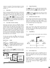
Respect to its sync pulse. These pulse parameters are shown in figure 3-2. Specific setups for each mode are given in paragraph 3.3. 3.2.1 white marks when first becoming familiar with the 801, the white mark settings are handy. The white mark settings for the front panel switches will always give a...
The output norm/comp switch could also be used to reverse the upper and lower levels as the trigger edge does, but some error could be introduced by the x-y multiplier. Control operation 3.2.9 rise time measurements when measuring rise time in a linear device under test, the error induced by the ris...
3.3.5 pulses with width controlled externally connect the trigger source to trig input and set the con- trols as follows. Control operation mode ext width trigger set as desired. (observe trig indicator to ensure triggering occurs.) edge controls and output controls set as desired. 3.3.6 triggered b...


