- DL manuals
- Xerox
- Copier
- DocuColor 2006 s
- Service Manual
Xerox DocuColor 2006 s Service Manual
Summary of DocuColor 2006 s
Page 1
March 2001 701p35949 phaser 790/docucolor 2006 service manual t he d ocument c ompany xerox caution certain components in the phaser 790/docucolor 2006 are susceptible to damage from electrostatic discharge. Observe all esd procedures to avoid component damage..
Page 2
Warning this equipment generates, uses and can radiate radio frequency energy, and if not installed and used in accordance with the instruc- tions documentation, may cause interference to radio communica- tions. It has been tested and found to comply with the limits for a class a computing device pu...
Page 3
10/00 i phaser 790/docucolor 2006 introduction initial issue introduction about this manual ........................................................................................................... Iii organization ......................................................................................
Page 4
10/00 ii phaser 790/docucolor 2006 initial issue introduction.
Page 5
10/00 iii phaser 790/docucolor 2006 introduction initial issue about this manual this service manual is part of the multinational documentation system for the phaser 790 printer and dc 2006 copier./printer the service documentation is used in order to diagnose machine malfunctions, adjust components...
Page 6
10/00 iv phaser 790/docucolor 2006 initial issue introduction warnings, cautions, and notes warnings, cautions, and notes will be found throughout the service documentation. The words warning or caution may be listed on an illustration when the specific component associated with the potential hazard...
Page 7
10/00 v phaser 790/docucolor 2006 introduction initial issue danger label indicates where electrical currents exist when the machine is closed and operat- ing. Use caution when reaching in the machine. These symbols indicate components that may be damaged by electrostatic discharge (esd). Electrosta...
Page 8
10/00 vi phaser 790/docucolor 2006 initial issue introduction voltage measurement and specifications measurements of dc voltage must be made with reference to the specified dc common, unless some other point is referenced in a diagnostic procedure. All measurements of ac volt- age should be made wit...
Page 9
10/00 1-1 phaser 790/docucolor 2006 service call procedures initial issue 1 service call procedures service call procedures.................................................................................................. 1-3 initial actions procedure ...................................................
Page 10
10/00 1-2 phaser 790/docucolor 2006 initial issue service call procedures.
Page 11
10/00 1-3 phaser 790/docucolor 2006 service call procedures, initial actions procedure service call procedures initial issue service call procedures service strategy the service strategy for the phaser 790 printer and the dc 2006 copier/printer is to run to fail- ure. The repair analysis procedures ...
Page 12
10/00 1-4 phaser 790/docucolor 2006 call flow procedure initial issue service call procedures call flow procedure this procedure should be performed at every service call. Procedure the copier/printer is capable of making a copy/print to the output tray. Y n the copier/printer is capable of making a...
Page 13
10/00 1-5 phaser 790/docucolor 2006 cleaning procedures, final actions service call procedures initial issue cleaning procedures purpose the purpose is to provide cleaning procedures to be performed at every call. Procedure caution do not use any solvents unless directed to do so by the service manu...
Page 14
10/00 1-6 phaser 790/docucolor 2006 cleaning procedures, final actions initial issue service call procedures.
Page 15
10/00 2-1 phaser 790/docucolor 2006 status indicator raps initial issue 2 status indicator raps fault message cross-reference fault message/rap cross-reference ............................................................................ 2-3 standby power 001-701 ac power rap ...........................
Page 16
10/00 2-2 phaser 790/docucolor 2006 initial issue status indicator raps 009-359 btr 2 bias rap ............................................................................................... 2-152 009-360 developer fan rap ................................................................................
Page 17
10/00 2-3 phaser 790/docucolor 2006 fault message/rap cross-reference status indicator raps initial issue fault message/rap cross-reference note: for all adf jam messages displayed on the scanner display, go to the 005-700 rap. For all scanner error messages displayed on the scanner display, which d...
Page 18
10/00 2-4 phaser 790/docucolor 2006 fault message/rap cross-reference initial issue status indicator raps.
Page 19
10/00 2-5 phaser 790/docucolor 2006 001-701 status indicator raps initial issue 001-701 ac power rap initial actions • ensure ac power is available at the wall receptacle. • ensure the power cord is good. Replace the power cord if it is defective (pl 11.1). Procedure switch off the power. Remove the...
Page 20
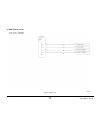
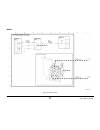
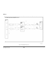
10/00 2-6 phaser 790/docucolor 2006 001-701 initial issue status indicator raps figure 1 001-701 circuit diagram.
Page 21
10/00 2-7 phaser 790/docucolor 2006 001-702 status indicator raps initial issue 001-702 +5 vdc power rap initial actions • ensure ac power is available at the wall receptacle. • ensure the power cord is good. Replace the power cord if it is defective (pl 11.1). Procedure switch off the power. Remove...
Page 22
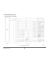
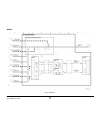
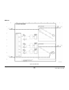
10/00 2-8 phaser 790/docucolor 2006 001-702 initial issue status indicator raps figure 1 001-702 circuit diagram.
Page 23
10/00 2-9 phaser 790/docucolor 2006 001-703 status indicator raps initial issue 001-703 +24 vdc interlocked power rap initial actions ensure the left front cover, the registration/bypass tray drawer, and the main fuser assem- bly are closed and in the correct position. Ensure that the actuator for t...
Page 24
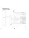
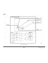
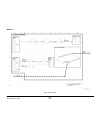
10/00 2-10 phaser 790/docucolor 2006 001-703 initial issue status indicator raps figure 1 001-703 circuit diagram.
Page 25
10/00 2-11 phaser 790/docucolor 2006 001-704 status indicator raps initial issue 001-704 front cover open rap initial actions ensure the right front cover is closed and that the actuator for the interlock is not damaged. Procedure access the digital input (di) test from the control panel. Enter code...
Page 26
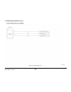
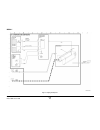
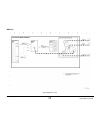
10/00 2-12 phaser 790/docucolor 2006 001-704 initial issue status indicator raps figure 1 001-704 circuit diagram.
Page 27
10/00 2-13 phaser 790/docucolor 2006 001-705 status indicator raps initial issue 001-705 ros +5 vdc switched voltage rap initial actions check the following: • ensure the right front cover is closed. • ensure the top cover is correctly positioned and is actuating the top cover interlock. Procedure s...
Page 28
10/00 2-14 phaser 790/docucolor 2006 001-705 initial issue status indicator raps figure 1 001-705 circuit diagram.
Page 29
10/00 2-15 phaser 790/docucolor 2006 001-706 status indicator raps initial issue 001-706 area 1 open rap initial actions perform the following: • check the actuator for the bypass tray interlock. Ensure it is not broken or damaged. • ensure the bypass tray is closed and is in the operating position....
Page 30
10/00 2-16 phaser 790/docucolor 2006 001-706 initial issue status indicator raps figure 1 001-706 circuit diagram.
Page 31
10/00 2-17 phaser 790/docucolor 2006 001-707 status indicator raps initial issue 001-707 area 2 open rap initial actions perform the following: • check the actuator for the turn chute interlock. Ensure it is not broken or damaged. • ensure the turn chute is closed. Procedure access the digital input...
Page 32
10/00 2-18 phaser 790/docucolor 2006 001-707 initial issue status indicator raps figure 1 001-707 circuit diagram.
Page 33
10/00 2-19 phaser 790/docucolor 2006 001-708 status indicator raps initial issue 001-708 area 3 open rap initial actions perform the following: • ensure the right cover is fully closed. • check the actuators for both feeder right cover switches. Ensure they are not broken or damaged. Procedure acces...
Page 34
10/00 2-20 phaser 790/docucolor 2006 001-708 initial issue status indicator raps figure 1 001-708 circuit diagram.
Page 35
10/00 2-21 phaser 790/docucolor 2006 001-709 status indicator raps initial issue 001-709 area 4 open rap initial actions perform the following: • check the actuator for the exit chute interlock. Ensure it is not broken or damaged. • ensure the exit chute is closed. Procedure access the digital input...
Page 36
10/00 2-22 phaser 790/docucolor 2006 001-709 initial issue status indicator raps figure 1 001-709 circuit diagram.
Page 37
10/00 2-23 phaser 790/docucolor 2006 001-710 status indicator raps initial issue 001-710 area 5 open rap the control logic detected that the fuser drawer in not fully closed. Initial actions perform the following: • ensure that the fuser assembly is fully closed. • ensure that the fuser assembly is ...
Page 38
10/00 2-24 phaser 790/docucolor 2006 001-710 initial issue status indicator raps figure 1 001-710 circuit diagram.
Page 39
10/00 2-25 phaser 790/docucolor 2006 001-711 status indicator raps initial issue 001-711 area 6 open rap the control logic has detected that area 6 is open. Initial actions perform the following: • ensure that the inverter chute (pl 15.5) is fully closed. • ensure that the actuator for the cab inter...
Page 40
10/00 2-26 phaser 790/docucolor 2006 001-711 initial issue status indicator raps figure 1 001-711 circuit diagram.
Page 41
10/00 2-27 phaser 790/docucolor 2006 001-712 status indicator raps initial issue 001-712 iit dc power rap initial actions ensure ac power is available at the wall outlet. Ensure that the ac power cord is securely connected to the system. Procedure remove the rear cover (rep 6.4) from the iit. Check ...
Page 42
10/00 2-28 phaser 790/docucolor 2006 001-712 initial issue status indicator raps figure 1 001-712 circuit diagram.
Page 43
10/00 2-29 phaser 790/docucolor 2006 002-310, 002-701 status indicator raps initial issue 002-310 iit control panel failure rap the iit control panel has failed. Procedure check the cable between the icm main pwb and the control panel for any pinched wires. Check the connectors for any loose or dama...
Page 44
10/00 2-30 phaser 790/docucolor 2006 002-701 initial issue status indicator raps figure 1 002-701 circuit diagram.
Page 45
10/00 2-31 phaser 790/docucolor 2006 002-702 status indicator raps initial issue 002-702 iot control panel button/led rap initial actions reseat the connectors on the cable between the ess pwb and the control panel (p/j34 and p/j 317. Check for any loose or damaged pins in the harness connectors. Pr...
Page 46
10/00 2-32 phaser 790/docucolor 2006 002-702 initial issue status indicator raps.
Page 47
10/00 2-33 phaser 790/docucolor 2006 003-310 status indicator raps initial issue 003-310 feeder communications failure rap the control logic detected a communication failure with the feeder pwb. Initial actions • ensure that connector p/j 212 is properly seated on the feeder pwb. • remove the ess pw...
Page 48
10/00 2-34 phaser 790/docucolor 2006 003-310 initial issue status indicator raps figure 1 003-310 rap circuit diagram.
Page 49
10/00 2-35 phaser 790/docucolor 2006 003-311 status indicator raps initial issue 003-311 duplex communications failure rap the control logic detected a communication failure with the duplex controller pwb. Initial actions • ensure that connector p/j 142 is properly seated on the duplex controller pw...
Page 50
10/00 2-36 phaser 790/docucolor 2006 003-311 initial issue status indicator raps figure 1 003-311 rap circuit diagram.
Page 51
10/00 2-37 phaser 790/docucolor 2006 003-312 status indicator raps initial issue 003-312 sorter communications failure rap the sorter control logic did not successfully receive the start signal from the mcu pwb. Procedure go to flag 1 and check the wires for an open or short circuit. The wires are g...
Page 52
10/00 2-38 phaser 790/docucolor 2006 003-312 initial issue status indicator raps figure 1 003-311 rap circuit diagram.
Page 53
10/00 2-39 phaser 790/docucolor 2006 003-333 status indicator raps initial issue 003-333 foreign interface rap this fault code indicates that a communications failure was detected between the ess pwb and the foreign interface. Procedure switch the iot power off, then on. Fault code 003-333 is still ...
Page 54
10/00 2-40 phaser 790/docucolor 2006 003-333 initial issue status indicator raps figure 1 003-333 rap circuit diagram.
Page 55
10/00 2-41 phaser 790/docucolor 2006 003-334 status indicator raps initial issue 003-334 foreign interface compatibility rap this fault code indicates that a compatibility problem was detected between the ess pwb and the foreign interface (an incorrect foreign interface device may be installed). Pro...
Page 56
10/00 2-42 phaser 790/docucolor 2006 003-334 initial issue status indicator raps figure 1 003-334 rap circuit diagram.
Page 57
10/00 2-43 phaser 790/docucolor 2006 003-356 status indicator raps initial issue 003-356 iot nvm ram error rap the system detected an iot nv ram error at power on. Procedure switch the power off then switch the power on. The fault code occurs. Y n if the problem seems to be intermittent, reseat all ...
Page 58
10/00 2-44 phaser 790/docucolor 2006 003-356 initial issue status indicator raps figure 1 003-356 rap circuit diagram.
Page 59
10/00 2-45 phaser 790/docucolor 2006 003-400, 003-701 status indicator raps initial issue 003-400 iot firmware error rap the system detected an iot firmware error. Procedure switch the power off then switch the power on. The fault code occurs. Y n if the problem seems to be intermittent, reseat all ...
Page 60
10/00 2-46 phaser 790/docucolor 2006 003-701 initial issue status indicator raps figure 1 003-701 rap circuit diagram.
Page 61
10/00 2-47 phaser 790/docucolor 2006 004-320 status indicator raps initial issue 004-320 paper handling motor rap the control logic detected that the paper handling motor is not functioning. Initial actions check the connectors on the drive motor pwb. Ensure that they are correctly seated. Procedure...
Page 62
10/00 2-48 phaser 790/docucolor 2006 004-320 initial issue status indicator raps figure 1 004-320 rap circuit diagram.
Page 63
10/00 2-49 phaser 790/docucolor 2006 004-322 status indicator raps initial issue 004-322 fuser motor rap the control logic detected that the fuser motor is not functioning. Initial actions check the connectors on the drive motor pwb and the fuser motor. Ensure that they are cor- rectly seated. Proce...
Page 64
10/00 2-50 phaser 790/docucolor 2006 004-322 initial issue status indicator raps figure 1 004-322 rap circuit diagram.
Page 65
10/00 2-51 phaser 790/docucolor 2006 005-210 status indicator raps initial issue 005-210 nudger home rap the signal, nudger home (l), is not detected within 1 second after adf drive motor is ener- gized. Procedure switch off the power. Remove the adf rear cover. Observe the nudger roll as the power ...
Page 66
10/00 2-52 phaser 790/docucolor 2006 005-210 initial issue status indicator raps figure 1 005-210 rap circuit diagram nudger roll.
Page 67
10/00 2-53 phaser 790/docucolor 2006 005-211 status indicator raps initial issue 005-211 adf power rap adf motor power error procedure remove the adf rear cover. There is +24 vdc from pin 11 to pin 12 on j811. Y n go to flag 1. Check for an open circuit. If the wires are ok, go to the 001-712 rap. C...
Page 68
10/00 2-54 phaser 790/docucolor 2006 005-211 initial issue status indicator raps figure 1 005-211 rap circuit diagram.
Page 69
10/00 2-55 phaser 790/docucolor 2006 005-220/221 status indicator raps initial issue 005-220/221 adf communications rap adf communication error procedure there is +5 vdc from pin 9 to pin 10 on j811. Y n go to flag 4. Check for an open circuit. If the wires are ok, replace the icm main pwb (pl 16.2)...
Page 70
10/00 2-56 phaser 790/docucolor 2006 005-220/221 initial issue status indicator raps figure 1 005-220/221 rap circuit diagram.
Page 71
10/00 2-57 phaser 790/docucolor 2006 005-700 status indicator raps initial issue 005-700 adf fault entry rap procedure use the following table to troubleshoot adf problems that do not generate a fault code. Table 1 problem description troubleshooting adf not recognized. Copies made from platen glass...
Page 72
10/00 2-58 phaser 790/docucolor 2006 005-701 initial issue status indicator raps 005-701 adf entrance jam rap procedure the green led of the document set indicator is always lit. Y n remove the adf rear cover. There is +5 vdc from j 814 pin 5 to frame ground. Y n disconnect p/j 712. There is +5 vdc ...
Page 73
10/00 2-59 phaser 790/docucolor 2006 005-701 status indicator raps initial issue figure 1 005-701 rap circuit diagram.
Page 74
10/00 2-60 phaser 790/docucolor 2006 005-702 initial issue status indicator raps 005-702 adf exit jam rap procedure remove the adf rear cover. Enter copy mode. Place a sheet of paper into the entrance tray. Press the start button. The adf exit motor energizes. Y n switch off the power. Disconnect th...
Page 75
10/00 2-61 phaser 790/docucolor 2006 005-702 status indicator raps initial issue figure 1 005-702 rap circuit diagram exit sensor exit motor.
Page 76
10/00 2-62 phaser 790/docucolor 2006 005-703 initial issue status indicator raps 005-703 adf no feed rap procedure open, then close the upper chute cover. The adf drive motor cycles. Y n go to flag 3. Check for an open circuit. If the wire is ok, replace the adf control pwb (pl 17.2). If the problem...
Page 77
10/00 2-63 phaser 790/docucolor 2006 005-703 status indicator raps initial issue figure 1 005-703 rap circuit diagram.
Page 78
10/00 2-64 phaser 790/docucolor 2006 005-704 initial issue status indicator raps 005-704 unfinished copy job rap procedure go to flag 1 and flag 2. Check the wires for an open circuit. If the wires are ok, replace the icm main pwb (pl 16.2)..
Page 79
10/00 2-65 phaser 790/docucolor 2006 005-704 status indicator raps initial issue figure 1 005-704 rap circuit diagram.
Page 80
10/00 2-66 phaser 790/docucolor 2006 005-704 initial issue status indicator raps.
Page 81
10/00 2-67 phaser 790/docucolor 2006 006-310 status indicator raps initial issue 006-310 iit registration rap the control logic has not detected the signal iit registration sensor sensed (h) +5 vdc at the correct time. Initial actions check the carriage motor drive components, including the belt (pl...
Page 82
10/00 2-68 phaser 790/docucolor 2006 006-310 initial issue status indicator raps figure 1 006-310 rap circuit diagram.
Page 83
10/00 2-69 phaser 790/docucolor 2006 006-311 status indicator raps initial issue 006-311 exposure lamp rap the ccd does not detect any light from the lamp. Initial actions ensure that mirrors 1, 2, and 3 (pl 16.5) are in place and not damaged or blocked with debris. Procedure access iit diagnostics ...
Page 84
10/00 2-70 phaser 790/docucolor 2006 006-312 initial issue status indicator raps 006-312 fpc ccd rap the fpc ccd does not provide the correct output when originals are scanned. Procedure note: the ccd is not field replaceable. If this fault code occurs, replace the following parts in the order shown...
Page 85
10/00 2-71 phaser 790/docucolor 2006 006-313 status indicator raps initial issue 006-313 iit cooling fans rap the front or rear cooling fan (or both fans) failed to operate correctly. A fan fail error has been declared. Procedure remove the right cover rep 6.2. Access the iit self diagnostics from t...
Page 86
10/00 2-72 phaser 790/docucolor 2006 006-313 initial issue status indicator raps figure 1 006-313 rap circuit diagram.
Page 87
10/00 2-73 phaser 790/docucolor 2006 006-372 status indicator raps initial issue 006-372 start of scan error rap during or after warm-up, the start of scan (sos) signal is longer than specified. Procedure switch off the power. Remove the iot top cover assembly (rep 14.4). Remove the control- ler cha...
Page 88
10/00 2-74 phaser 790/docucolor 2006 006-372 initial issue status indicator raps figure 1 006-372 rap circuit diagram.
Page 89
10/00 2-75 phaser 790/docucolor 2006 006-701 status indicator raps initial issue 006-701 angle sensor rap the angle sensor circuit has failed to operate correctly. Initial actions procedure remove the rear cover rep 6.4. Disconnect connector j 130 from the icm main pwb. +5 vdc is measured between j1...
Page 90
10/00 2-76 phaser 790/docucolor 2006 006-701 initial issue status indicator raps figure 1 006-701 rap circuit diagram.
Page 91
10/00 2-77 phaser 790/docucolor 2006 006-702 status indicator raps initial issue 006-702 platen switch rap the platen switch circuit has failed to operate correctly. Initial actions visually check to ensure that the magnet that actuates the platen switch is securely in place. Procedure remove the re...
Page 92
10/00 2-78 phaser 790/docucolor 2006 006-702 initial issue status indicator raps figure 1 006-702 rap circuit diagram.
Page 93
10/00 2-79 phaser 790/docucolor 2006 006-703, 006-704 status indicator raps initial issue 006-703 scanner error rap procedure switch the power off, then on. If the fault remains, replace the ips pwb (pl 16.2). If this does not resolve the problem, replace the icm main pwb (pl 16.2). 006-704 system e...
Page 94
10/00 2-80 phaser 790/docucolor 2006 006-906/907/908/909 initial issue status indicator raps 006-906/907/908/909 rap 006-906: control logic detected an aoc1 error at job start or initialization. 006-907: control logic detected an agc error. 006-908: control logic detected an oe pixel judgement error...
Page 95
10/00 2-81 phaser 790/docucolor 2006 007-324 status indicator raps initial issue 007-324 environment sensor rap the control logic has detected an open circuit in the environment sensor. Initial actions • ensure that the environment sensor is free of dust and dirt. Procedure switch off the power. Dis...
Page 96
10/00 2-82 phaser 790/docucolor 2006 007-324 initial issue status indicator raps figure 1 007-324 rap circuit diagram.
Page 97
10/00 2-83 phaser 790/docucolor 2006 007-340 status indicator raps initial issue 007-340 feeder motor fail rap the control logic has detected the signal, feeder motor fail (h) +5 vdc. Procedure enter [do-b8]. The feeder motor is operating. Y n there is +24 vdc from j 213 pin 1 on the feeder pwb to p...
Page 98
10/00 2-84 phaser 790/docucolor 2006 007-340 initial issue status indicator raps figure 1 007-340 rap circuit diagram.
Page 99
10/00 2-85 phaser 790/docucolor 2006 007-341 status indicator raps initial issue 007-341 inverter motor fail rap the control logic has detected an inverter motor fail (h) +5 vdc signal. Initial actions ensure that the upper and the lower inverter assemblies are properly closed. Procedure enter diagn...
Page 100
10/00 2-86 phaser 790/docucolor 2006 007-341 initial issue status indicator raps figure 1 007-341 rap circuit diagram.
Page 101
10/00 2-87 phaser 790/docucolor 2006 007-700 status indicator raps initial issue 007-700 tray 1 open rap the control logic detected the absence of the analog signal size switch sensed voltage for tray 1. Initial actions ensure that paper tray 1 is closed. Procedure the paper tray is properly seated ...
Page 102
10/00 2-88 phaser 790/docucolor 2006 007-700 initial issue status indicator raps figure 1 007-700 rap circuit diagram.
Page 103
10/00 2-89 phaser 790/docucolor 2006 007-701 status indicator raps initial issue 007-701 tray 2 open rap the control logic detected the absence of the analog signal size switch sensed voltage for tray 2. Initial actions ensure that paper tray 2 is closed. Procedure the paper tray is properly seated ...
Page 104
10/00 2-90 phaser 790/docucolor 2006 007-701 initial issue status indicator raps figure 1 007-701 rap circuit diagram.
Page 105
10/00 2-91 phaser 790/docucolor 2006 007-702 status indicator raps initial issue 007-702 tray 3 open rap the control logic detected the absence of the analog signal size switch sensed voltage for tray 3. Initial actions ensure that paper tray 3 is closed. Procedure the paper tray is properly seated ...
Page 106
10/00 2-92 phaser 790/docucolor 2006 007-702 initial issue status indicator raps figure 1 007-702 rap circuit diagram.
Page 107
10/00 2-93 phaser 790/docucolor 2006 007-703 status indicator raps initial issue 007-703 tray 1 empty rap the tray 1 no paper sensed signal is detected by the control logic. Initial actions • check that the tray 1 lift plate functions without binding. • ensure the tray 1 is filled with 250 sheets of...
Page 108
10/00 2-94 phaser 790/docucolor 2006 007-703 initial issue status indicator raps figure 1 007-703 rap circuit diagram.
Page 109
10/00 2-95 phaser 790/docucolor 2006 007-704 status indicator raps initial issue 007-704 tray 2 empty rap the control logic detected the signal, no paper sensed (h) +5vdc. Initial actions • put paper into tray 2 and ensure that the paper is loaded properly. Procedure remove paper from tray 2. Check ...
Page 110
10/00 2-96 phaser 790/docucolor 2006 007-704 initial issue status indicator raps figure 1 007-704 rap circuit diagram.
Page 111
10/00 2-97 phaser 790/docucolor 2006 007-705 status indicator raps initial issue 007-705 tray 3 empty rap the control logic detected the signal, no paper sensor sensed (h) +5vdc. Initial actions • put paper into tray 3 and ensure that the paper is loaded properly. Procedure remove paper tray 3. Chec...
Page 112
10/00 2-98 phaser 790/docucolor 2006 007-705 initial issue status indicator raps figure 1 007-705 rap circuit diagram.
Page 113
10/00 2-99 phaser 790/docucolor 2006 007-706 status indicator raps initial issue 007-706 bypass tray empty rap the control logic has detected a tray empty sensor sensed (h) +5 vdc. Initial actions • load paper into the bypass tray. • check the bypass tray and ensure that the tray empty actuator is p...
Page 114
10/00 2-100 phaser 790/docucolor 2006 007-706 initial issue status indicator raps figure 1 007-706 rap circuit diagram.
Page 115
10/00 2-101 phaser 790/docucolor 2006 007-707 status indicator raps initial issue 007-707 paper length mismatch rap initial actions ensure that the paper tray is properly loaded with paper and the side guides are in the proper position. Procedure determine which paper tray is being used when the pro...
Page 116
10/00 2-102 phaser 790/docucolor 2006 007-708 initial issue status indicator raps 007-708 bypass tray lift rap initial actions ensure that paper is placed in the bypass tray. Procedure enter the diagnostic mode. Enter [do-23]. The lift plate goes up. Y n check the following: • check the lift mechani...
Page 117
10/00 2-103 phaser 790/docucolor 2006 007-708 status indicator raps initial issue figure 1 007-708 rap circuit diagram.
Page 118
10/00 2-104 phaser 790/docucolor 2006 007-709 initial issue status indicator raps 007-709 tray 2 lift up rap the control logic has detected that tray 2 is not in position to feed paper. Initial actions check that the tray lift mechanism, within paper tray 2, functions correctly. Procedure switch off...
Page 119
10/00 2-105 phaser 790/docucolor 2006 007-709 status indicator raps initial issue figure 1 007-709 rap circuit diagram (1 of 2).
Page 120
10/00 2-106 phaser 790/docucolor 2006 007-709 initial issue status indicator raps figure 2 007-709 rap circuit diagram (2 of 2).
Page 121
10/00 2-107 phaser 790/docucolor 2006 007-710 status indicator raps initial issue 007-710 tray 3 lift up rap the control logic has detected that tray 3 is not in position to feed paper. Initial actions check that the tray lift mechanism, within paper tray 3, functions correctly. Procedure switch off...
Page 122
10/00 2-108 phaser 790/docucolor 2006 007-710 initial issue status indicator raps figure 1 007-710 rap circuit diagram (1 of 2).
Page 123
10/00 2-109 phaser 790/docucolor 2006 007-710 status indicator raps initial issue figure 2 007-710 rap circuit diagram (2 of 2).
Page 124
10/00 2-110 phaser 790/docucolor 2006 007-711 initial issue status indicator raps 007-711 tray 1 paper size not detected rap the control logic detected that the wrong size paper is feeding from tray 1. Initial actions ensure that the paper in tray 1 is properly installed and that the tray side and e...
Page 125
10/00 2-111 phaser 790/docucolor 2006 007-711 status indicator raps initial issue figure 1 007-711 rap circuit diagram.
Page 126
10/00 2-112 phaser 790/docucolor 2006 007-712 initial issue status indicator raps 007-712 tray 2 paper size not detected rap the control logic detected that the wrong size paper is feeding from tray 2. Initial actions ensure that the paper in tray 2 is properly installed and that the tray side and e...
Page 127
10/00 2-113 phaser 790/docucolor 2006 007-712 status indicator raps initial issue figure 1 007-712 rap circuit diagram.
Page 128
10/00 2-114 phaser 790/docucolor 2006 007-713 initial issue status indicator raps 007-713 tray 3 paper size not detected rap the control logic detected that the wrong size paper is feeding from tray 3. Initial actions ensure that the paper in tray 3 is properly installed and that the tray side and e...
Page 129
10/00 2-115 phaser 790/docucolor 2006 007-713 status indicator raps initial issue figure 1 007-713 rap circuit diagram.
Page 130
10/00 2-116 phaser 790/docucolor 2006 007-713 initial issue status indicator raps.
Page 131
10/00 2-117 phaser 790/docucolor 2006 008-700 status indicator raps initial issue 008-700 area 1 jam rap the registration sensor or the ohp sensor in the bypass tray assembly transport, has detected a registration sensed (l) +5 vdc or an ohp sensed (l) +5 vdc, at the incorrect time. Initial actions ...
Page 132
10/00 2-118 phaser 790/docucolor 2006 008-700 initial issue status indicator raps figure 1 008-700 rap circuit diagram (1 of 2).
Page 133
10/00 2-119 phaser 790/docucolor 2006 008-700 status indicator raps initial issue figure 2 008-700 rap circuit diagram (2 of 2).
Page 134
10/00 2-120 phaser 790/docucolor 2006 008-701 initial issue status indicator raps 008-701 area 2 jam rap the control logic has detected the signal, duplex entrance sensor (l) +5 vdc or the control logic did not detect the signal, registration sensed (l) +5 vdc within the set time limit. Initial acti...
Page 135
10/00 2-121 phaser 790/docucolor 2006 008-701 status indicator raps initial issue figure 1 008-701 rap circuit diagram (1 of 2).
Page 136
10/00 2-122 phaser 790/docucolor 2006 008-701 initial issue status indicator raps figure 2 008-701 rap circuit diagram (2 of 2).
Page 137
10/00 2-123 phaser 790/docucolor 2006 008-702 status indicator raps initial issue 008-702 area 3 jam rap the control logic has detected the signal feed out sensed (l) +5 vdc at an incorrect time. This signal can originate from the tray 2 feed out sensor or the tray 3 feed out sensor. Initial actions...
Page 138
10/00 2-124 phaser 790/docucolor 2006 008-702 initial issue status indicator raps figure 1 008-702 rap circuit diagram.
Page 139
10/00 2-125 phaser 790/docucolor 2006 008-703 status indicator raps initial issue 008-703 area 4 jam rap the control logic has detected the signal paper at top exit sensor (l) +5 vdc at the incorrect time. Initial actions • open the top left cover and remove any paper from area 4. • ensure that the ...
Page 140
10/00 2-126 phaser 790/docucolor 2006 008-703 initial issue status indicator raps figure 1 008-703 rap circuit diagram.
Page 141
10/00 2-127 phaser 790/docucolor 2006 008-704 status indicator raps initial issue 008-704 area 6 jam rap the control logic had detected the signal, inverter sensor sensed (l) +5 vdc at an incorrect time. Initial actions • clear the jam from the lower inverter assembly. • check that the lower inverte...
Page 142
10/00 2-128 phaser 790/docucolor 2006 008-704 initial issue status indicator raps figure 1 008-704 rap circuit diagram (1 of 2).
Page 143
10/00 2-129 phaser 790/docucolor 2006 008-704 status indicator raps initial issue figure 2 008-704 rap circuit diagram (2 of 2).
Page 144
10/00 2-130 phaser 790/docucolor 2006 008-705 initial issue status indicator raps 008-705 top tray full rap the control logic has sensed the signal, top tray full (l) +5 vdc. Initial actions • remove any paper from the top tray. • unlock the full stack sensor actuator, so that the actuator will oper...
Page 145
10/00 2-131 phaser 790/docucolor 2006 008-705 status indicator raps initial issue figure 1 008-705 rap circuit diagram.
Page 146
10/00 2-132 phaser 790/docucolor 2006 008-706 initial issue status indicator raps 008-706 ohp sensor rap the control logic has sensed the signal, ohp sensed (l) +5 vdc at an incorrect time. Initial actions pull out the bypass tray/ paper transport assembly and remove the ohp transparency from the re...
Page 147
10/00 2-133 phaser 790/docucolor 2006 008-706 status indicator raps initial issue figure 1 008-706 rap circuit diagram.
Page 148
10/00 2-134 phaser 790/docucolor 2006 008-707 initial issue status indicator raps 008-707 duplex tray open rap the control logic did not detect a duplex tray set (l) +5 vdc signal. Initial actions push in the duplex tray assembly. Procedure go to flag 1. Check the wires for an open. Check the pins i...
Page 149
10/00 2-135 phaser 790/docucolor 2006 008-707 status indicator raps initial issue figure 1 008-707 rap circuit diagram.
Page 150
10/00 2-136 phaser 790/docucolor 2006 008-707 initial issue status indicator raps.
Page 151
10/00 2-137 phaser 790/docucolor 2006 009-321 status indicator raps initial issue 009-321 tr0 sensor rap the tr0 sensor did not detect the ibt belt in the home position within the specified time. Procedure access the digital output test (gp 2). Enter code 54. Press the item/enter button. The pro- ce...
Page 152
10/00 2-138 phaser 790/docucolor 2006 009-321 initial issue status indicator raps figure 1 009-321 rap circuit diagram.
Page 153
10/00 2-139 phaser 790/docucolor 2006 009-323 status indicator raps initial issue 009-323 process motor rap control logic detected the signal, process motor fail (h) +5vdc. Procedure access the digital output test (gp 2). Enter code 54. Press the item/enter button. The pro- cess motor energizes. Y n...
Page 154
10/00 2-140 phaser 790/docucolor 2006 009-323 initial issue status indicator raps figure 1 009-323 rap circuit diagram.
Page 155
10/00 2-141 phaser 790/docucolor 2006 009-326 status indicator raps initial issue 009-326 rotary motor rap one of the following situations occurred: • the rotary sensor did not detect the rotary frame assy. In the home position within 6 seconds from the signal, rotary motor on. • during a print job,...
Page 156
10/00 2-142 phaser 790/docucolor 2006 009-326 initial issue status indicator raps figure 1 009-326 rap circuit diagram.
Page 157
10/00 2-143 phaser 790/docucolor 2006 009-340 status indicator raps initial issue 009-340 adc cleaning failure rap output of adc sensor is below limit immediately after cleaning. Procedure access the digital output test (gp 2). Enter code 67. Press the item/enter button. There is an audible click fr...
Page 158
10/00 2-144 phaser 790/docucolor 2006 009-340 initial issue status indicator raps figure 1 009-340 rap circuit diagram.
Page 159
10/00 2-145 phaser 790/docucolor 2006 009-341 status indicator raps initial issue 009-341 adc sensor background rap control logic has determined that the adc sensor output while measuring non-imaged area is higher than specification. Procedure warning high voltage! Exercise care when making the volt...
Page 160
10/00 2-146 phaser 790/docucolor 2006 009-341 initial issue status indicator raps figure 1 009-341 rap circuit diagram.
Page 161
10/00 2-147 phaser 790/docucolor 2006 009-342 status indicator raps initial issue 009-342 patch error rap adc sensor output measuring cin 50% patch area is lower than spec. After adjustment procedure access the digital output test (gp 2). Enter code 53. Press the item/enter button. Enter code 56. Pr...
Page 162
10/00 2-148 phaser 790/docucolor 2006 009-342 initial issue status indicator raps figure 1 009-342 rap circuit diagram.
Page 163
10/00 2-149 phaser 790/docucolor 2006 009-343, 009-344 status indicator raps initial issue 009-343 pcdc error rap pcdc cal count below 100 procedure switch off the power, then switch on the power. If the fault is still present, replace the mcu pwb (pl 11.2). 009-344 image density error rap image den...
Page 164
10/00 2-150 phaser 790/docucolor 2006 009-358 initial issue status indicator raps 009-358 btr 2 home position rap the btr 2 cam sensor does not detect the cam in the home position within the specified time procedure the btr 2 cam clutch is always energized y n access the digital output test (gp 2). ...
Page 165
10/00 2-151 phaser 790/docucolor 2006 009-358 status indicator raps initial issue figure 1 009-358 rap circuit diagram.
Page 166
10/00 2-152 phaser 790/docucolor 2006 009-359 initial issue status indicator raps 009-359 btr 2 bias rap the output current monitor value for btr 2 bias is outside of the allowable range. Procedure there is +24 vdc from j 42 pin 10 to j 42 pin 13 on the high voltage power supply. Y n go to flag 1 an...
Page 167
10/00 2-153 phaser 790/docucolor 2006 009-359 status indicator raps initial issue figure 1 009-359 rap circuit diagram.
Page 168
10/00 2-154 phaser 790/docucolor 2006 009-360 initial issue status indicator raps 009-360 developer fan rap control logic detects the signal, fan alarm (l) +5 vdc. Procedure access the digital output test (gp 2). Enter code 61. Press the item/enter button. The developer fan energizes. Y n there is +...
Page 169
10/00 2-155 phaser 790/docucolor 2006 009-360 status indicator raps initial issue figure 1 009-360 rap circuit diagram.
Page 170
10/00 2-156 phaser 790/docucolor 2006 009-700 initial issue status indicator raps 009-700 toner cartridge detached rap control logic does not detect the presence of one or more dry ink cartridges. Initial actions if the fault is reported for a single cartridge, check the outboard end of the cartridg...
Page 171
10/00 2-157 phaser 790/docucolor 2006 009-700 status indicator raps initial issue figure 1 009-700 rap circuit diagram front.
Page 172
10/00 2-158 phaser 790/docucolor 2006 009-701 initial issue status indicator raps 009-701 toner cartridge empty rap adc sensor detects a drop in toner concentration (tc) that is not restored by dispense oper- ation. Initial actions if a single color is declaring the fault, replace the dry ink cartri...
Page 173
10/00 2-159 phaser 790/docucolor 2006 009-701 status indicator raps initial issue figure 1 009-701 rap circuit diagram.
Page 174
10/00 2-160 phaser 790/docucolor 2006 009-702 initial issue status indicator raps 009-702 waste container full rap control logic detects that the waste container is full. Initial actions check the waste container. Replace if required. If the message is displayed with an empty or partially full waste...
Page 175
10/00 2-161 phaser 790/docucolor 2006 009-702 status indicator raps initial issue figure 1 009-702 rap circuit diagram.
Page 176
10/00 2-162 phaser 790/docucolor 2006 009-703 initial issue status indicator raps 009-703 waste container detached rap control logic does not detect the presence of the waste container. Initial actions check that the waste container is present and is installed correctly. Procedure access the digital...
Page 177
10/00 2-163 phaser 790/docucolor 2006 009-703 status indicator raps initial issue figure 1 009-703 rap circuit diagram.
Page 178
10/00 2-164 phaser 790/docucolor 2006 009-704 initial issue status indicator raps 009-704 belt cleaner rap initial actions open the fuser assembly. Check for wear or damage to the cleaner cam followers (pl 8.6). Ensure that the belt cleaner assembly is installed correctly and freely moves up and dow...
Page 179
10/00 2-165 phaser 790/docucolor 2006 009-704 status indicator raps initial issue figure 1 009-704 rap circuit diagram.
Page 180
10/00 2-166 phaser 790/docucolor 2006 009-704 initial issue status indicator raps.
Page 181
10/00 2-167 phaser 790/docucolor 2006 010-317 status indicator raps initial issue 010-317 temperature sensor circuit error rap a disconnection / open circuit has been detected in the temperature sensor circuit. Initial actions inspect the fuser area for debris and other signs of wear, breakage or da...
Page 182
10/00 2-168 phaser 790/docucolor 2006 010-353/356/357 initial issue status indicator raps 010-353/356/357 fuser low/under temperature condition rap • 010-353 - a fuser low temperature error has been declared. One of the following condi- tions exist: – an abnormally low fuser temperature has been det...
Page 183
10/00 2-169 phaser 790/docucolor 2006 010-353/356/357 status indicator raps initial issue figure 1 010-353 rap circuit diagram.
Page 184
10/00 2-170 phaser 790/docucolor 2006 010-354 initial issue status indicator raps 010-354 fuser temperature not detected rap the fuser temperature cannot be correctly sensed by the temperature sensor. A fuser tem- perature error was declared. Initial actions inspect the fuser area for debris and oth...
Page 185
10/00 2-171 phaser 790/docucolor 2006 010-354 status indicator raps initial issue figure 1 010-354 rap circuit diagram.
Page 186
10/00 2-172 phaser 790/docucolor 2006 010-355 initial issue status indicator raps 010-355 fuser overheat error rap the sensed fuser temperature has exceeded the maximum allowable temperature. A fuser overheat error was declared. Initial actions inspect the fuser area (especially around the temperatu...
Page 187
10/00 2-173 phaser 790/docucolor 2006 010-355 status indicator raps initial issue figure 1 010-355 rap circuit diagram.
Page 188
10/00 2-174 phaser 790/docucolor 2006 010-358 initial issue status indicator raps 010-358 fuser fan error rap the fuser fan has failed to operate correctly. A fuser fan rotation error has been declared. Initial actions ensure that there are no obstructions or physical conditions that might inhibit n...
Page 189
10/00 2-175 phaser 790/docucolor 2006 010-358 status indicator raps initial issue figure 1 010-358 rap circuit diagram.
Page 190
10/00 2-176 phaser 790/docucolor 2006 010-359 initial issue status indicator raps 010-359 exit chute fan failure rap the exit chute fan has failed to operate correctly. An exit chute fan rotation error has been declared. Initial actions ensure that there are no obstructions or physical conditions th...
Page 191
10/00 2-177 phaser 790/docucolor 2006 010-359 status indicator raps initial issue figure 1 010-359 rap circuit diagram.
Page 192
10/00 2-178 phaser 790/docucolor 2006 010-700 initial issue status indicator raps 010-700 area 5 jam rap one of the following conditions exists or was detected: • the fuser exit sensor does not detect paper within a specified period of time after the reg clutch is energized. • the trail edge of a sh...
Page 193
10/00 2-179 phaser 790/docucolor 2006 010-700 status indicator raps initial issue.
Page 194
10/00 2-180 phaser 790/docucolor 2006 010-701 initial issue status indicator raps 010-701 faulty temperature sensor rap the temperature sensor has failed to read the fuser temperature correctly. A temperature sensor error has been declared. Initial actions inspect the fuser area for debris and other...
Page 195
10/00 2-181 phaser 790/docucolor 2006 010-701 status indicator raps initial issue figure 1 010-701 rap circuit diagram.
Page 196
10/00 2-182 phaser 790/docucolor 2006 010-702 initial issue status indicator raps 010-702 faulty entrance sensor rap the fuser entrance sensor did not detect paper within a specified period of time after a sheet was available at the sensor. An entrance sensor error was declared. Initial actions chec...
Page 197
10/00 2-183 phaser 790/docucolor 2006 010-702 status indicator raps initial issue figure 1 010-702 rap circuit diagram.
Page 198
10/00 2-184 phaser 790/docucolor 2006 010-703 initial issue status indicator raps 010-703 faulty fuser exit sensor rap one of the following conditions exists or was detected: • the fuser exit sensor did not detect paper within a specified period of time after the regi clutch was energized. • the fus...
Page 199
10/00 2-185 phaser 790/docucolor 2006 010-703 status indicator raps initial issue figure 1 010-703 rap circuit diagram.
Page 200
10/00 2-186 phaser 790/docucolor 2006 010-704 initial issue status indicator raps 010-704 faulty fuser chute fan rap use this procedure to troubleshoot an intermittent or faulty fuser chute fan. No fault code or error message is associated with the failure of this component. Initial actions ensure t...
Page 201
10/00 2-187 phaser 790/docucolor 2006 010-704 status indicator raps initial issue figure 1 010-704 rap circuit diagram.
Page 202
10/00 2-188 phaser 790/docucolor 2006 010-705 initial issue status indicator raps 010-705 faulty exchange solenoid rap the exchange solenoid failed to operate correctly causing an error message or a fault code to be displayed. Initial actions note: the resistance value of the exchange solenoid shoul...
Page 203
10/00 2-189 phaser 790/docucolor 2006 010-705 status indicator raps initial issue figure 1 010-705 rap circuit diagram.
Page 204
10/00 2-190 phaser 790/docucolor 2006 010-705 initial issue status indicator raps.
Page 205
10/00 2-191 phaser 790/docucolor 2006 011-700 status indicator raps initial issue 011-700 sorter not in correct position rap sorter control pwb logic has detected that the sorter is not docked correctly. Initial actions • ensure that the sorter is completely and correctly docked by pushing the sorte...
Page 206
10/00 2-192 phaser 790/docucolor 2006 011-700 initial issue status indicator raps figure 1 011-700 rap circuit diagram.
Page 207
10/00 2-193 phaser 790/docucolor 2006 011-701 status indicator raps initial issue 011-701 sorter bin jam rap sorter control pwb logic did not detect paper at the sorter path sensor within 600 ms (the same amount of time allowed for the bins to move one level) after the last sheet has left the sorter...
Page 208
10/00 2-194 phaser 790/docucolor 2006 011-701 initial issue status indicator raps there is +5 vdc between p 10-3 and gnd. Y n go to flag 7. Check for an open circuit. The wire is good. Y n repair the wire. Go to flag 8. Check for an open circuit. The wires are good. Y n repair the wires. Replace the...
Page 209
10/00 2-195 phaser 790/docucolor 2006 011-701 status indicator raps initial issue figure 1 011-701 rap circuit diagram.
Page 210
10/00 2-196 phaser 790/docucolor 2006 011-702 initial issue status indicator raps 011-702 sorter cover open rap sorter control pwb logic has detected that the sorter top cover is open. Initial actions switch off the copier/printer then switch on the copier/printer to try and clear the “close sorter ...
Page 211
10/00 2-197 phaser 790/docucolor 2006 011-702 status indicator raps initial issue figure 1 011-702 rap circuit diagram.
Page 212
10/00 2-198 phaser 790/docucolor 2006 011-703 initial issue status indicator raps 011-703 sorter transport jam rap sorter control pwb logic did not detect paper at the sorter path sensor within a specified time after the fuser exit sensor detected paper. Initial actions • check for an obstruction in...
Page 213
10/00 2-199 phaser 790/docucolor 2006 011-703 status indicator raps initial issue figure 1 011-703 rap circuit diagram.
Page 214
10/00 2-200 phaser 790/docucolor 2006 011-704 initial issue status indicator raps 011-704 sorter noise rap there is noise emanating from the sorter at power up. Procedure there is +5 vdc between j 8-10 of the sorter control pwb and gnd. Y n there is +5 vdc between j35-4 of the low voltage power supp...
Page 215
10/00 2-201 phaser 790/docucolor 2006 011-704 status indicator raps initial issue figure 1 011-704 rap circuit diagram.
Page 216
10/00 2-202 phaser 790/docucolor 2006 011-705 initial issue status indicator raps 011-705 full sensor rap the sorter control pwb incorrectly detected that the stack tray is full. Procedure remove any paper from the stack tray. Access the digital input (di) test from the control panel. Enter code [d0...
Page 217
10/00 2-203 phaser 790/docucolor 2006 011-705 status indicator raps initial issue figure 1 011-705 rap circuit diagram.
Page 218
10/00 2-204 phaser 790/docucolor 2006 011-706 initial issue status indicator raps 011-706 cannot select sorter rap control logic did not detect the sorter. Procedure go to flag 1. Check the wires for an open circuit. The wires are good. Y n repair the wires. Replace the sorter control pwb (pl 19.1)....
Page 219
10/00 2-205 phaser 790/docucolor 2006 011-706 status indicator raps initial issue figure 1 011-706 rap circuit diagram.
Page 220
10/00 2-206 phaser 790/docucolor 2006 011-706 initial issue status indicator raps.
Page 221
10/00 2-207 phaser 790/docucolor 2006 016-310, 016-312 status indicator raps initial issue 016-310 font rom checksum error rap control logic detected a font rom checksum error procedure switch off the power then switch on the power. If the problem still exists, replace the ess pwb (pl 12.1). 016-312...
Page 222
10/00 2-208 phaser 790/docucolor 2006 016-313, 016-315 initial issue status indicator raps 016-313 asic access error rap control logic detected a asic access error procedure switch off the power then switch on the power. If the problem still exists, replace the ess pwb (pl 12.1). 016-315 ess ram (ba...
Page 223
10/00 2-209 phaser 790/docucolor 2006 016-316, 016-317 status indicator raps initial issue 016-316 ess ram (bank 2) rap control logic detected an ess ram read/write check error from bank 2 procedure switch off the power. Reseat the memory module in slot 2. Switch on the power. If the fault remains, ...
Page 224
10/00 2-210 phaser 790/docucolor 2006 016-323/324/325, 016-330/331/332/333/334/335/336 initial issue status indicator raps 016-323/324/325 ess nvm ram failure rap 016-323: the control logic detected an ess nvram1 (billing) failure. 016-324: the control logic detected an ess nvram2 (billing) failure....
Page 225
10/00 2-211 phaser 790/docucolor 2006 016-370 status indicator raps initial issue 016-370 iot to ess communication failure rap the control logic detected an iot to ess communication failure. Procedure perform the following: • switch off the power. Remove the right cover in order to access the ess pw...
Page 226
10/00 2-212 phaser 790/docucolor 2006 016-370 initial issue status indicator raps.
Page 227
10/00 2-213 phaser 790/docucolor 2006 033-210, 033-211/212 status indicator raps initial issue 033-210 printer detection rap connection with the printer failed. Procedure switch off the power, then switch on the power. If the fault is still present, replace the icm main pwb (pl 16.2). 033-211/212 io...
Page 228
10/00 2-214 phaser 790/docucolor 2006 033-221/222/223/224/225/226/226/227/228, 033-330/ initial issue status indicator raps 033-221/222/223/224/225/226/226/227/228 iot/iit communication rap 033-221: the control logic detects a 1394 pwb communication time-out. 033-222: the control logic detects a 139...
Page 229
10/00 2-215 phaser 790/docucolor 2006 033-340/341/342/343/344/345, 033-360/361/370/371 status indicator raps initial issue 033-340/341/342/343/344/345/350 asic error rap 033-340: an asic_a read/write error was detected. 033-341: an asic_b read/write error was detected. 033-342: an asic_c read/write ...
Page 230
10/00 2-216 phaser 790/docucolor 2006 033-380/390, 033-921/922/930/934/935/936/937 initial issue status indicator raps 033-380/390 1394 failure rap 033-380: a 1394 pwb initilization error was detected. 033-380: a 1394 pwb hardware failure was detected. Procedure switch the power off, then on. If the...
Page 231
10/00 2-217 phaser 790/docucolor 2006 033-940/941/943/944/945 status indicator raps initial issue 033-940/941/943/944/945 scsi error rap 033-940: the control logic detects a scsi parity error. 033-941: the control logic detects that an about message has been received. 033-943: the control logic dete...
Page 232
10/00 2-218 phaser 790/docucolor 2006 033-940/941/943/944/945 initial issue status indicator raps.
Page 233
10/00 3-1 phaser 790/docucolor 2006 image quality initial issue 3 image quality iq1 iot image quality entry rap .................................................................................. 3-3 iq2 iit image quality entry rap ........................................................................
Page 234
10/00 3-2 phaser 790/docucolor 2006 initial issue image quality.
Page 235
10/00 3-3 phaser 790/docucolor 2006 iq1 image quality initial issue iq1 iot image quality entry rap the purpose of this rap is to serve as the entrance vehicle into the image quality raps sec- tion. All image quality raps must be accessed through this rap. The rap will have you evaluate the copies m...
Page 236
10/00 3-4 phaser 790/docucolor 2006 iq1 initial issue image quality regular (repeating) bands, streaks, spots or smears a defect that repeats at an interval from14 to 264 mm, is most noticeable in low density (20-30%) halftone areas of the copy, and runs perpendicular to process direction. Lines and...
Page 237
10/00 3-5 phaser 790/docucolor 2006 iq2 image quality initial issue iq2 iit image quality entry rap this rap is for troubleshooting iit (scanner/adf) problems only. Before proceeding, verify that the defect is present in copy mode only. If the defect is present in print mode, go to the iq1 rap. Init...
Page 238
10/00 3-6 phaser 790/docucolor 2006 iq3 initial issue image quality iq3 low image density rap this rap troubleshoots the causes of output images showing image density lower than speci- fication initial actions • replace the paper in use with fresh, dry paper of the correct specification • determine ...
Page 239
10/00 3-7 phaser 790/docucolor 2006 iq4, iq5 image quality initial issue iq4 high density rap initial actions • check the end-of-life counters for the dry ink cartridges and the copy/print cartridge (gp 3). Replace if required. • perform visualcal. If this does not resolve the problem, continue with...
Page 240
10/00 3-8 phaser 790/docucolor 2006 iq6 initial issue image quality iq6 blank (or nearly blank) sheet rap initial actions • check the end-of-life counters for the dry ink cartridge and the copy/print cartridge (gp 3). Replace if required. Procedure warning high voltage! Exercise caution when perform...
Page 241
10/00 3-9 phaser 790/docucolor 2006 iq6 image quality initial issue figure 1 iq6 rap circuit diagram.
Page 242
10/00 3-10 phaser 790/docucolor 2006 iq7 initial issue image quality iq7 residual image (ghosting) rap initial actions • check the end-of-life counter for the copy/print cartridge (gp 3). If the unit is at or near end-of-life, replace the copy/print cartridge (pl 5.1). • if the problem occurs only w...
Page 243
10/00 3-11 phaser 790/docucolor 2006 iq7 image quality initial issue figure 1 iq7 rap circuit diagram.
Page 244
10/00 3-12 phaser 790/docucolor 2006 iq8 initial issue image quality iq8 iot background rap initial actions • check the end-of-life counter (gp 3) for the copy/print cartridge. If it is at or near end-of- life, replace it (pl 5.1). • perform visualcal (gp 16). If this does not resolve the problem, c...
Page 245
10/00 3-13 phaser 790/docucolor 2006 iq8 image quality initial issue.
Page 246
10/00 3-14 phaser 790/docucolor 2006 iq9 initial issue image quality iq9 deletions rap initial actions reload the machine with fresh, dry paper of the correct specifications. If the problem occurs when using heavyweight paper, ensure that the correct selections are being made on the print driver. If...
Page 247
10/00 3-15 phaser 790/docucolor 2006 iq9 image quality initial issue figure 1 iq9 rap circuit diagram.
Page 248
10/00 3-16 phaser 790/docucolor 2006 iq10, iq11 initial issue image quality iq10 color-to-color misregistration rap procedure the problem is misregistration in the process direction. Y n remove the copy/print cartridge. Move the tension lever to the locked position. Check that there is adequate tens...
Page 249
10/00 3-17 phaser 790/docucolor 2006 iq12, iq13 image quality initial issue iq12 iit skew rap procedure make a copy in platen mode. The defect is present. Y n the problem is skew. Y n check/adjust adf side registration (adj 5.1) and adf lead edge registration (adj 5.2). Check/adjust the adf height (...
Page 250
10/00 3-18 phaser 790/docucolor 2006 iq14, iq15 initial issue image quality iq14 process direction bands, streaks, and smears rap procedure the defect occurs every print (letter size). Y n the defect occurs every second print (letter size). Y n if the defect occurs intermittently, examine the develo...
Page 251
10/00 3-19 phaser 790/docucolor 2006 iq16 image quality initial issue iq16 repeating bands, streaks, spots, and smears rap procedure measure the distance between the repeating defects. Locate the distance on the table below. Perform the indicated repair actions table 1 repeating defects repetition s...
Page 252
10/00 3-20 phaser 790/docucolor 2006 iq17 initial issue image quality iq17 uneven density/mottle rap this rap troubleshoots the causes of output images showing image density that varies from inboard to outboard edges, or randomly throughout the print. Initial actions • replace the paper in use with ...
Page 253
10/00 3-21 phaser 790/docucolor 2006 iq18 image quality initial issue iq18 spots rap initial actions ensure that the paper in use is fresh, dry, and within specification for weight and quality. Compare the spots against the samples in the image quality defects supplement. If the defect matches the d...
Page 254
10/00 3-22 phaser 790/docucolor 2006 iq18 initial issue image quality.
Page 255
10/00 4-1 phaser 790/docucolor 2006 repairs and adjustments initial issue 4 repairs and adjustments electrical rep 1.1 lvps................................................................................................................. 4-5 rep 1.2 hvps .................................................
Page 256
10/00 4-2 phaser 790/docucolor 2006 initial issue repairs and adjustments rep 8.22 feeder drive unit/low paper sensor ............................................................. 4-73 rep 8.23 paper feeder assembly ................................................................................. 4-...
Page 257
10/00 4-3 phaser 790/docucolor 2006 repairs and adjustments initial issue adj 5.3 adf height ........................................................................................................ 4-150 adj 5.4 adf front-to-rear positioning .............................................................
Page 258
10/00 4-4 phaser 790/docucolor 2006 initial issue repairs and adjustments.
Page 259
10/00 4-5 phaser 790/docucolor 2006 rep 1.1, rep 1.2 repairs and adjustments initial issue rep 1.1 lvps parts list on pl 11.1 removal warning to avoid personal injury or shock, do not perform repair activities with the power switch on or electrical power applied to the machine. 1. Switch off the mac...
Page 260
10/00 4-6 phaser 790/docucolor 2006 rep 1.3, rep 1.4 initial issue repairs and adjustments rep 1.3 top cover interlock parts list on pl 11.1 removal warning to avoid personal injury or shock, do not perform repair activities with the power switch on or electrical power applied to the machine. 1. Swi...
Page 261
10/00 4-7 phaser 790/docucolor 2006 rep 1.5 repairs and adjustments initial issue rep 1.5 mcu pwb parts list on pl 11.2 removal warning to avoid personal injury or shock, do not perform repair activities with the power switch on or electrical power applied to the machine. Caution before replacing th...
Page 262
10/00 4-8 phaser 790/docucolor 2006 rep 1.6, rep 1.7 initial issue repairs and adjustments rep 1.6 right front cover interlock parts list on pl 11.2 removal warning to avoid personal injury or shock, do not perform repair activities with the power switch on or electrical power applied to the machine...
Page 263
10/00 4-9 phaser 790/docucolor 2006 rep 1.8 repairs and adjustments initial issue rep 1.8 environment sensor parts list on pl 11.2 removal warning to avoid personal injury or shock, do not perform repair activities with the power switch on or electrical power applied to the machine. 1. Switch off th...
Page 264
10/00 4-10 phaser 790/docucolor 2006 rep 1.9 initial issue repairs and adjustments rep 1.9 ess pwb parts list on pl 12.1 removal warning to avoid personal injury or shock, do not perform repair activities with the power switch on or electrical power applied to the machine. 2. Switch off the machine ...
Page 265
10/00 4-11 phaser 790/docucolor 2006 rep 1.10, rep 1.11 repairs and adjustments initial issue rep 1.10 ess fan parts list on pl 12.1 removal warning to avoid personal injury or shock, do not perform repair activities with the power switch on or electrical power applied to the machine. 1. Switch off ...
Page 266
10/00 4-12 phaser 790/docucolor 2006 rep 1.12 initial issue repairs and adjustments rep 1.12 communication pwb parts list on pl 11.2 removal warning to avoid personal injury or shock, do not perform repair activities with the power switch on or electrical power applied to the machine. 1. Switch off ...
Page 267
10/00 4-13 phaser 790/docucolor 2006 rep 1.13 repairs and adjustments initial issue rep 1.13 hard disk drive assembly parts list on pl 12.1 removal warning to avoid personal injury or shock, do not perform repair activities with the power switch on or electrical power applied to the machine. 1. Swit...
Page 268
10/00 4-14 phaser 790/docucolor 2006 rep 1.13 initial issue repairs and adjustments.
Page 269
10/00 4-15 phaser 790/docucolor 2006 rep 4.1 repairs and adjustments initial issue rep 4.1 paper handling drive unit parts list on pl 10.1 removal warning to avoid personal injury or shock, do not perform repair activities with the power switch on or electrical power applied to the machine. 1. Switc...
Page 270
10/00 4-16 phaser 790/docucolor 2006 rep 4.2 initial issue repairs and adjustments rep 4.2 fuser drive unit parts list on pl 10.1 removal warning to avoid personal injury or shock, do not perform repair activities with the power switch on or electrical power applied to the machine. 1. Switch off the...
Page 271
10/00 4-17 phaser 790/docucolor 2006 rep 4.3, rep 4.4 repairs and adjustments initial issue rep 4.3 fuser motor parts list on pl 10.1 removal warning to avoid personal injury or shock, do not perform repair activities with the power switch on or electrical power applied to the machine. 1. Switch off...
Page 272
10/00 4-18 phaser 790/docucolor 2006 rep 4.5 initial issue repairs and adjustments rep 4.5 drive motor pwb parts list on pl 10.1 removal warning to avoid personal injury or shock, do not perform repair activities with the power switch on or electrical power applied to the machine. 1. Switch off the ...
Page 273
10/00 4-19 phaser 790/docucolor 2006 rep 4.6 repairs and adjustments initial issue rep 4.6 process drive unit parts list on pl 10.1 removal warning to avoid personal injury or shock, do not perform repair activities with the power switch on or electrical power applied to the machine. 1. Switch off t...
Page 274
10/00 4-20 phaser 790/docucolor 2006 rep 4.7, rep 4.8 initial issue repairs and adjustments rep 4.7 rotary motor parts list on pl 10.1 removal warning to avoid personal injury or shock, do not perform repair activities with the power switch on or electrical power applied to the machine. 1. Switch of...
Page 275
10/00 4-21 phaser 790/docucolor 2006 rep 4.9, rep 4.10 repairs and adjustments initial issue rep 4.9 dispense clutch parts list on pl 10.1 removal warning to avoid personal injury or shock, do not perform repair activities with the power switch on or electrical power applied to the machine. 1. Switc...
Page 276
10/00 4-22 phaser 790/docucolor 2006 rep 4.9, rep 4.10 initial issue repairs and adjustments.
Page 277
10/00 4-23 phaser 790/docucolor 2006 rep 5.1 repairs and adjustments initial issue rep 5.1 adf assembly parts list on pl 17.1 removal warning to avoid personal injury or shock, do not perform repair activities with the power switch on or electrical power applied to the machine. 1. Switch off the mac...
Page 278
10/00 4-24 phaser 790/docucolor 2006 rep 5.2, rep 5.3 initial issue repairs and adjustments rep 5.2 adf drive motor parts list on pl 17.2 removal warning to avoid personal injury or shock, do not perform repair activities with the power switch on or electrical power applied to the machine. 1. Switch...
Page 279
10/00 4-25 phaser 790/docucolor 2006 rep 5.4 repairs and adjustments initial issue rep 5.4 feed roll parts list on pl 17.3 removal warning to avoid personal injury or shock, do not perform repair activities with the power switch on or electrical power applied to the machine. 1. Switch off the machin...
Page 280
10/00 4-26 phaser 790/docucolor 2006 rep 5.4, rep 5.5 initial issue repairs and adjustments replacement 1. Perform the procedure for removal in reverse. During replacement, pay close attention to the following step. 2. The one way clutch is attached to the gear. Install the gear so that the shaft ro...
Page 281
10/00 4-27 phaser 790/docucolor 2006 rep 5.5 repairs and adjustments initial issue 5. Remove the lower chute. (figure 2) figure 2 removing the lower chute 6. Remove the nudger roll assembly parts. (figure 3) figure 3 removing nudger roll retaining parts 1 open the feeder cover 2 loosen the screw 3 r...
Page 282
10/00 4-28 phaser 790/docucolor 2006 rep 5.5 initial issue repairs and adjustments 7. Remove the nudger roll. (figure 4) figure 4 removing the nudger roll replacement 1. Perform the procedure for removal in reverse. Pay close attention to the following step. 2. The one way clutch is attached to the ...
Page 283
10/00 4-29 phaser 790/docucolor 2006 rep 5.6 repairs and adjustments initial issue rep 5.6 registration roll parts list on pl 17.3 removal warning to avoid personal injury or shock, do not perform repair activities with the power switch on or electrical power applied to the machine. 1. Switch off th...
Page 284
10/00 4-30 phaser 790/docucolor 2006 rep 5.6 initial issue repairs and adjustments 8. Move the registration pinch roll away from the registration roll. Caution tension springs are of different strengths for the front and rear. Be careful not to mix the front and rear springs when removing them from ...
Page 285
10/00 4-31 phaser 790/docucolor 2006 rep 5.7 repairs and adjustments initial issue rep 5.7 document transport assembly parts list on pl 17.6 removal warning to avoid personal injury or shock, do not perform repair activities with the power switch on or electrical power applied to the machine. 1. Swi...
Page 286
10/00 4-32 phaser 790/docucolor 2006 rep 5.8 initial issue repairs and adjustments rep 5.8 platen belt parts list on pl 17.6 removal warning to avoid personal injury or shock, do not perform repair activities with the power switch on or electrical power applied to the machine. 1. Switch off the mach...
Page 287
10/00 4-33 phaser 790/docucolor 2006 rep 5.9 repairs and adjustments initial issue rep 5.9 adf exit motor parts list on pl 17.7 removal warning to avoid personal injury or shock, do not perform repair activities with the power switch on or electrical power applied to the machine. 1. Switch off the m...
Page 288
10/00 4-34 phaser 790/docucolor 2006 rep 5.10 initial issue repairs and adjustments rep 5.10 adf exit sensor and exit tray interlock parts list on pl 17.7 removal warning to avoid personal injury or shock, do not perform repair activities with the power switch on or electrical power applied to the m...
Page 289
10/00 4-35 phaser 790/docucolor 2006 rep 5.10 repairs and adjustments initial issue 5. Remove the exit tray interlock or adf exit sensor. (figure 3) figure 3 removing the exit tray interlock or adf exit sensor replacement 1. Perform the procedure for removal in reverse. Pay close attention to the fo...
Page 290
10/00 4-36 phaser 790/docucolor 2006 rep 5.10 initial issue repairs and adjustments.
Page 291
10/00 4-37 phaser 790/docucolor 2006 rep 6.1, rep 6.2 repairs and adjustments initial issue rep 6.1 platen glass parts list on pl 16.1 removal 1. Remove the adf (rep 5.1) or platen cover. 2. Remove the platen glass (figure 1). Figure 1 removing the platen glass replacement 1. Perform the procedure f...
Page 292
10/00 4-38 phaser 790/docucolor 2006 rep 6.3, rep 6.4 initial issue repairs and adjustments rep 6.3 left cover parts list on pl 16.6 removal 1. Remove the left cover (figure 1). Figure 1 removing the left cover replacement 1. Perform the procedure for removal in reverse. Rep 6.4 rear cover parts lis...
Page 293
10/00 4-39 phaser 790/docucolor 2006 rep 6.5, rep 6.6 repairs and adjustments initial issue rep 6.5 angle sensor parts list on pl 16.1 removal warning to avoid personal injury or shock, do not perform repair activities with the power switch on or electrical power applied to the machine. 1. Switch of...
Page 294
10/00 4-40 phaser 790/docucolor 2006 rep 6.7 initial issue repairs and adjustments rep 6.7 registration sensor parts list on pl 16.1 removal warning to avoid personal injury or shock, do not perform repair activities with the power switch on or electrical power applied to the machine. 1. Switch off ...
Page 295
10/00 4-41 phaser 790/docucolor 2006 rep 6.8, rep 6.9 repairs and adjustments initial issue rep 6.8 iit low voltage power supply (lvps) parts list on pl 16.1 removal warning to avoid personal injury or shock, do not perform repair activities with the power switch on or electrical power applied to th...
Page 296
10/00 4-42 phaser 790/docucolor 2006 rep 6.10 initial issue repairs and adjustments rep 6.10 aps sensor parts list on pl 16.1 removal warning to avoid personal injury or shock, do not perform repair activities with the power switch on or electrical power applied to the machine. 1. Switch off the mac...
Page 297
10/00 4-43 phaser 790/docucolor 2006 rep 6.11 repairs and adjustments initial issue rep 6.11 pwb box parts list on pl 16.1 removal warning to avoid personal injury or shock, do not perform repair activities with the power switch on or electrical power applied to the machine. 1. Switch off the machin...
Page 298
10/00 4-44 phaser 790/docucolor 2006 rep 6.11 initial issue repairs and adjustments 9. Disconnect the connectors from the icm main pwb (right rear) (figure 3). Figure 3 disconnecting the iit icm pwb connectors 10. Remove the screws holding the pwb box to the iit frame (figure 4). Figure 4 accessing ...
Page 299
10/00 4-45 phaser 790/docucolor 2006 rep 6.12, rep 6.13 repairs and adjustments initial issue rep 6.12 pwb box cover parts list on pl 16.2 removal warning to avoid personal injury or shock, do not perform repair activities with the power switch on or electrical power applied to the machine. 1. Switc...
Page 300
10/00 4-46 phaser 790/docucolor 2006 rep 6.14 initial issue repairs and adjustments rep 6.14 icm main pwb parts list on pl 16.2 removal warning to avoid personal injury or shock, do not perform repair activities with the power switch on or electrical power applied to the machine. 1. Switch off the m...
Page 301
10/00 4-47 phaser 790/docucolor 2006 rep 6.15, rep 6.16 repairs and adjustments initial issue rep 6.15 extension pwb parts list on pl 16.2 removal warning to avoid personal injury or shock, do not perform repair activities with the power switch on or electrical power applied to the machine. 1. Switc...
Page 302
10/00 4-48 phaser 790/docucolor 2006 rep 6.16, rep 6.17 initial issue repairs and adjustments caution the pwb components are highly susceptible to damage from electrostatic discharge (esd) and extreme care should be used when handling these components. Use of the esd field service kit is required. 3...
Page 303
10/00 4-49 phaser 790/docucolor 2006 rep 6.17, rep 6.18 repairs and adjustments initial issue replacement 1. Install the front / rear cable assembly (figure 2). Figure 2 routing the cable assembly caution verify that the cable is not twisted and that the cable assembly is not contacting any surround...
Page 304
10/00 4-50 phaser 790/docucolor 2006 rep 6.19, rep 6.20 initial issue repairs and adjustments rep 6.19 belt parts list on pl 16.4 removal warning to avoid personal injury or shock, do not perform repair activities with the power switch on or electrical power applied to the machine. 1. Switch off the...
Page 305
10/00 4-51 phaser 790/docucolor 2006 rep 6.21, rep 6.22 repairs and adjustments initial issue rep 6.21 full-rate carriage assembly parts list on pl 16.5 removal warning to avoid personal injury or shock, do not perform repair activities with the power switch on or electrical power applied to the mac...
Page 306
10/00 4-52 phaser 790/docucolor 2006 rep 6.23 initial issue repairs and adjustments rep 6.23 control panel assembly parts list on pl 16.6 removal warning to avoid personal injury or shock, do not perform repair activities with the power switch on or electrical power applied to the machine. 1. Switch...
Page 307
10/00 4-53 phaser 790/docucolor 2006 rep 7.1, rep 7.2 repairs and adjustments initial issue rep 7.1 size switch pwb parts list on pl 3.1 removal warning to avoid personal injury or shock, do not perform repair activities with the power switch on or electrical power applied to the machine. 1. Switch ...
Page 308
10/00 4-54 phaser 790/docucolor 2006 rep 7.3, rep 7.4 initial issue repairs and adjustments rep 7.3 no paper sensor assembly parts list on pl 3.1 removal warning to avoid personal injury or shock, do not perform repair activities with the power switch on or electrical power applied to the machine. 1...
Page 309
10/00 4-55 phaser 790/docucolor 2006 rep 7.5, rep 7.6 repairs and adjustments initial issue rep 7.5 low paper sensor parts list on pl 3.1 removal warning to avoid personal injury or shock, do not perform repair activities with the power switch on or electrical power applied to the machine. 1. Switch...
Page 310
10/00 4-56 phaser 790/docucolor 2006 rep 7.7 initial issue repairs and adjustments rep 7.7 tray 1 front snubber parts list on pl 2.1 removal 1. Remove the tray 1 assembly. (rep 7.6) 2. Set the bottom plate to the raised position by actuating the plate link. (figure 1) figure 1 unlocking the bottom p...
Page 311
10/00 4-57 phaser 790/docucolor 2006 rep 7.8 repairs and adjustments initial issue figure 1 unlocking the bottom plate caution the area of the oversize tray front snubber that comes in contact with the paper is easily bent. Use care when handling the front snubber. Caution the front guide mounting p...
Page 312
10/00 4-58 phaser 790/docucolor 2006 rep 7.8 initial issue repairs and adjustments.
Page 313
10/00 4-59 phaser 790/docucolor 2006 rep 8.1 repairs and adjustments initial issue rep 8.1 turn roll parts list on pl 3.3 removal warning to avoid personal injury or shock, do not perform repair activities with the power switch on or electrical power applied to the machine. 1. Switch off the machine...
Page 314
10/00 4-60 phaser 790/docucolor 2006 rep 8.1, rep 8.2 initial issue repairs and adjustments 6. Remove the turn roll. (figure 3) figure 3 removing the turn roll replacement 1. Perform the procedure for removal in reverse. Note: when installing the stopper for the paper tray, position the paper tray a...
Page 315
10/00 4-61 phaser 790/docucolor 2006 rep 8.3 repairs and adjustments initial issue rep 8.3 feed roll assembly parts list on pl 3.3 removal warning to avoid personal injury or shock, do not perform repair activities with the power switch on or electrical power applied to the machine. 1. Switch off th...
Page 316
10/00 4-62 phaser 790/docucolor 2006 rep 8.4 initial issue repairs and adjustments rep 8.4 turn clutch parts list on pl 3.3 removal warning to avoid personal injury or shock, do not perform repair activities with the power switch on or electrical power applied to the machine. 1. Switch off the machi...
Page 317
10/00 4-63 phaser 790/docucolor 2006 rep 8.5 repairs and adjustments initial issue rep 8.5 feed solenoid parts list on pl 3.1 removal warning to avoid personal injury or shock, do not perform repair activities with the power switch on or electrical power applied to the machine. 1. Switch off the mac...
Page 318
10/00 4-64 phaser 790/docucolor 2006 rep 8.6, rep 8.7 initial issue repairs and adjustments rep 8.6 bypass tray/registration assembly parts list on pl 4.1 removal warning to avoid personal injury or shock, do not perform repair activities with the power switch on or electrical power applied to the m...
Page 319
10/00 4-65 phaser 790/docucolor 2006 rep 8.8, rep 8.9 repairs and adjustments initial issue rep 8.8 tray housing parts list on pl 4.1 removal warning to avoid personal injury or shock, do not perform repair activities with the power switch on or electrical power applied to the machine. 1. Switch off...
Page 320
10/00 4-66 phaser 790/docucolor 2006 rep 8.10, rep 8.11 initial issue repairs and adjustments rep 8.10 lift plate sensor parts list on pl 4.2 removal warning to avoid personal injury or shock, do not perform repair activities with the power switch on or electrical power applied to the machine. 1. Sw...
Page 321
10/00 4-67 phaser 790/docucolor 2006 rep 8.12, rep 8.13 repairs and adjustments initial issue rep 8.12 tray empty sensor parts list on pl 4.3 removal warning to avoid personal injury or shock, do not perform repair activities with the power switch on or electrical power applied to the machine. 1. Sw...
Page 322
10/00 4-68 phaser 790/docucolor 2006 rep 8.14 initial issue repairs and adjustments rep 8.14 stack height sensor parts list on pl 4.4 removal warning to avoid personal injury or shock, do not perform repair activities with the power switch on or electrical power applied to the machine. 1. Switch off...
Page 323
10/00 4-69 phaser 790/docucolor 2006 rep 8.15, rep 8.16 repairs and adjustments initial issue rep 8.15 preregistration clutch parts list on pl 4.6 removal warning to avoid personal injury or shock, do not perform repair activities with the power switch on or electrical power applied to the machine. ...
Page 324
10/00 4-70 phaser 790/docucolor 2006 rep 8.17, rep 8.18 initial issue repairs and adjustments rep 8.17 registration clutch parts list on pl 4.7 removal warning to avoid personal injury or shock, do not perform repair activities with the power switch on or electrical power applied to the machine. 1. ...
Page 325
10/00 4-71 phaser 790/docucolor 2006 rep 8.19 repairs and adjustments initial issue rep 8.19 size switch pwb parts list on pl 13.3 removal warning to avoid personal injury or shock, do not perform repair activities with the power switch on or electrical power applied to the machine. 1. Switch off th...
Page 326
10/00 4-72 phaser 790/docucolor 2006 rep 8.20, rep 8.21 initial issue repairs and adjustments rep 8.20 feeder motor parts list on pl 13.4 removal warning to avoid personal injury or shock, do not perform repair activities with the power switch on or electrical power applied to the machine. 1. Switch...
Page 327
10/00 4-73 phaser 790/docucolor 2006 rep 8.22 repairs and adjustments initial issue rep 8.22 feeder drive unit/low paper sensor parts list on pl 13.4 removal warning to avoid personal injury or shock, do not perform repair activities with the power switch on or electrical power applied to the machin...
Page 328
10/00 4-74 phaser 790/docucolor 2006 rep 8.23 initial issue repairs and adjustments rep 8.23 paper feeder assembly parts list on pl 13.5 removal warning to avoid personal injury or shock, do not perform repair activities with the power switch on or electrical power applied to the machine. 1. Switch ...
Page 329
10/00 4-75 phaser 790/docucolor 2006 rep 8.24, rep 8.25 repairs and adjustments initial issue rep 8.24 takeaway clutch parts list on pl 13.6 removal warning to avoid personal injury or shock, do not perform repair activities with the power switch on or electrical power applied to the machine. 1. Swi...
Page 330
10/00 4-76 phaser 790/docucolor 2006 rep 8.26, rep 8.27 initial issue repairs and adjustments rep 8.26 turn clutch parts list on pl 13.6 removal warning to avoid personal injury or shock, do not perform repair activities with the power switch on or electrical power applied to the machine. 1. Switch ...
Page 331
10/00 4-77 phaser 790/docucolor 2006 rep 8.28 repairs and adjustments initial issue rep 8.28 duplex entrance sensor parts list on pl 15.3 removal warning to avoid personal injury or shock, do not perform repair activities with the power switch on or electrical power applied to the machine. 1. Switch...
Page 332
10/00 4-78 phaser 790/docucolor 2006 rep 8.29 initial issue repairs and adjustments rep 8.29 duplex exit sensor parts list on pl 15.3 removal warning to avoid personal injury or shock, do not perform repair activities with the power switch on or electrical power applied to the machine. 1. Switch off...
Page 333
10/00 4-79 phaser 790/docucolor 2006 rep 8.29 repairs and adjustments initial issue 7. Remove the exit chute. (figure 4) figure 4 removing the exit chute 8. Remove the duplex exit sensor. (figure 5) figure 5 removing the duplex exit sensor replacement 1. Perform the removal procedure in reverse. 1 d...
Page 334
10/00 4-80 phaser 790/docucolor 2006 rep 8.30, rep 8.31 initial issue repairs and adjustments rep 8.30 duplex drive clutch parts list on pl 15.4 removal warning to avoid personal injury or shock, do not perform repair activities with the power switch on or electrical power applied to the machine. 1....
Page 335
10/00 4-81 phaser 790/docucolor 2006 rep 8.32, rep 8.33 repairs and adjustments initial issue rep 8.32 rear belt parts list on pl 15.4 removal warning to avoid personal injury or shock, do not perform repair activities with the power switch on or electrical power applied to the machine. 1. Switch of...
Page 336
10/00 4-82 phaser 790/docucolor 2006 rep 8.34 initial issue repairs and adjustments rep 8.34 exit roll parts list on pl 15.2 removal warning to avoid personal injury or shock, do not perform repair activities with the power switch on or electrical power applied to the machine. 1. Switch off the mach...
Page 337
10/00 4-83 phaser 790/docucolor 2006 rep 8.35, rep 8.36 repairs and adjustments initial issue rep 8.35 inverter/lower assembly parts list on pl 15.5 removal warning to avoid personal injury or shock, do not perform repair activities with the power switch on or electrical power applied to the machine...
Page 338
10/00 4-84 phaser 790/docucolor 2006 rep 8.36 initial issue repairs and adjustments 4. Remove the inverter motor. (figure 2) figure 2 removing the inverter motor replacement caution when installing the bracket, use care not to pinch the wires between the mounting surface and the bracket, or damage c...
Page 339
10/00 4-85 phaser 790/docucolor 2006 rep 8.37 repairs and adjustments initial issue rep 8.37 inverter sensor parts list on pl 15.5 removal warning to avoid personal injury or shock, do not perform repair activities with the power switch on or electrical power applied to the machine. 1. Switch off th...
Page 340
10/00 4-86 phaser 790/docucolor 2006 rep 8.38 initial issue repairs and adjustments rep 8.38 duplex controller pwb parts list on pl 15.6 removal warning to avoid personal injury or shock, do not perform repair activities with the power switch on or electrical power applied to the machine. 1. Switch ...
Page 341
10/00 4-87 phaser 790/docucolor 2006 rep 8.39 repairs and adjustments initial issue rep 8.39 duplex nip solenoid parts list on pl 15.1 removal warning to avoid personal injury or shock, do not perform repair activities with the power switch on or electrical power applied to the machine. 1. Switch of...
Page 342
10/00 4-88 phaser 790/docucolor 2006 rep 8.40 initial issue repairs and adjustments rep 8.40 exit transport assembly parts list on pl 9.1 removal warning to avoid personal injury or shock, do not perform repair activities with the power switch on or electrical power applied to the machine. 1. Switch...
Page 343
10/00 4-89 phaser 790/docucolor 2006 rep 8.41, rep 8.42 repairs and adjustments initial issue rep 8.41 full stack sensor parts list on pl 9.2 removal warning to avoid personal injury or shock, do not perform repair activities with the power switch on or electrical power applied to the machine. 1. Sw...
Page 344
10/00 4-90 phaser 790/docucolor 2006 rep 8.43 initial issue repairs and adjustments rep 8.43 top exit sensor parts list on pl 9.2 removal warning to avoid personal injury or shock, do not perform repair activities with the power switch on or electrical power applied to the machine. 1. Switch off the...
Page 345
10/00 4-91 phaser 790/docucolor 2006 rep 9.1, rep 9.2 repairs and adjustments initial issue rep 9.1 copy/print cartridge parts list on pl 5.1 removal warning to avoid personal injury or shock, do not perform repair activities with the power switch on or electrical power applied to the machine. 1. Sw...
Page 346
10/00 4-92 phaser 790/docucolor 2006 rep 9.3 initial issue repairs and adjustments rep 9.3 ros parts list on pl 5.1 removal warning to avoid personal injury or shock, do not perform repair activities with the power switch on or electrical power applied to the machine. 1. Switch off the machine power...
Page 347
10/00 4-93 phaser 790/docucolor 2006 rep 9.3 repairs and adjustments initial issue caution be careful not to touch the window of the ros (window from which laser beam is emitted) or other working components, such as the motor shaft, when removing the ros. The ros and the locating rail are connected ...
Page 348
10/00 4-94 phaser 790/docucolor 2006 rep 9.4 initial issue repairs and adjustments rep 9.4 adc sensor parts list on pl 5.1 removal warning to avoid personal injury or shock, do not perform repair activities with the power switch on or electrical power applied to the machine. 1. Switch off the machin...
Page 349
10/00 4-95 phaser 790/docucolor 2006 rep 9.5 repairs and adjustments initial issue rep 9.5 locating rail parts list on pl 5.1 removal warning to avoid personal injury or shock, do not perform repair activities with the power switch on or electrical power applied to the machine. 1. Switch off the mac...
Page 350
10/00 4-96 phaser 790/docucolor 2006 rep 9.6, rep 9.7 initial issue repairs and adjustments rep 9.6 waste toner sensor parts list on pl 5.1 removal warning to avoid personal injury or shock, do not perform repair activities with the power switch on or electrical power applied to the machine. 1. Swit...
Page 351
10/00 4-97 phaser 790/docucolor 2006 rep 9.8, rep 9.9 repairs and adjustments initial issue rep 9.8 erase lamp parts list on pl 5.1 removal warning to avoid personal injury or shock, do not perform repair activities with the power switch on or electrical power applied to the machine. 1. Switch off t...
Page 352
10/00 4-98 phaser 790/docucolor 2006 rep 9.10 initial issue repairs and adjustments rep 9.10 developer housing parts list on pl 6.2 removal warning to avoid personal injury or shock, do not perform repair activities with the power switch on or electrical power applied to the machine. 1. Switch off t...
Page 353
10/00 4-99 phaser 790/docucolor 2006 rep 9.11 repairs and adjustments initial issue rep 9.11 rotary sensor parts list on pl 6.1 removal warning to avoid personal injury or shock, do not perform repair activities with the power switch on or electrical power applied to the machine. 1. Switch off the m...
Page 354
10/00 4-100 phaser 790/docucolor 2006 rep 9.12 initial issue repairs and adjustments rep 9.12 rotary frame parts list on pl 6.1 removal warning to avoid personal injury or shock, do not perform repair activities with the power switch on or electrical power applied to the machine. 1. Switch off the m...
Page 355
10/00 4-101 phaser 790/docucolor 2006 rep 9.12 repairs and adjustments initial issue warning the rotary frame is very heavy. Be careful not to drop or touch other components while removing the rotary frame. Caution keep the front shaft of the rotary frame from falling from the machine while performi...
Page 356
10/00 4-102 phaser 790/docucolor 2006 rep 9.13 initial issue repairs and adjustments rep 9.13 cartridge sensor parts list on pl 6.1 removal warning to avoid personal injury or shock, do not perform repair activities with the power switch on or electrical power applied to the machine. 1. Switch off t...
Page 357
10/00 4-103 phaser 790/docucolor 2006 rep 9.14, rep 9.15 repairs and adjustments initial issue rep 9.14 developer tie plate parts list on pl 1.3 removal warning to avoid personal injury or shock, do not perform repair activities with the power switch on or electrical power applied to the machine. 1....
Page 358
10/00 4-104 phaser 790/docucolor 2006 rep 9.16 initial issue repairs and adjustments rep 9.16 ibt assembly parts list on pl 7.2 removal warning to avoid personal injury or shock, do not perform repair activities with the power switch on or electrical power applied to the machine. 1. Switch off the m...
Page 359
10/00 4-105 phaser 790/docucolor 2006 rep 9.17 repairs and adjustments initial issue rep 9.17 belt cleaner parts list on pl 7.1 removal warning to avoid personal injury or shock, do not perform repair activities with the power switch on or electrical power applied to the machine. 1. Switch off the m...
Page 360
10/00 4-106 phaser 790/docucolor 2006 rep 9.17, rep 9.18 initial issue repairs and adjustments replacement 1. Reinstall the belt cleaner (figure 2). 2. Reset the belt cleaner counter (counter clear). Figure 2 replacing the belt cleaner rep 9.18 btr 2 assembly parts list on pl 7.1 removal warning to ...
Page 361
10/00 4-107 phaser 790/docucolor 2006 rep 9.19 repairs and adjustments initial issue rep 9.19 btr 2 cam assembly parts list on pl 7.1 removal warning to avoid personal injury or shock, do not perform repair activities with the power switch on or electrical power applied to the machine. 1. Switch off...
Page 362
10/00 4-108 phaser 790/docucolor 2006 rep 9.20 initial issue repairs and adjustments rep 9.20 auger parts list on pl 7.1 removal warning to avoid personal injury or shock, do not perform repair activities with the power switch on or electrical power applied to the machine. 1. Switch off the machine ...
Page 363
10/00 4-109 phaser 790/docucolor 2006 rep 9.21 repairs and adjustments initial issue rep 9.21 ibt belt parts list on pl 7.2 removal warning to avoid personal injury or shock, do not perform repair activities with the power switch on or electrical power applied to the machine. 1. Switch off the machi...
Page 364
10/00 4-110 phaser 790/docucolor 2006 rep 9.21 initial issue repairs and adjustments 9. Stand the ibt assembly with its rear side at the bottom. Figure 3 removing the ibt belt 10. Remove the ibt belt from the assembly. Figure 4 removing the ibt belt replacement caution be careful not to damage or di...
Page 365
10/00 4-111 phaser 790/docucolor 2006 rep 9.22, rep 9.23 repairs and adjustments initial issue rep 9.22 tr0 sensor parts list on pl 7.3 removal warning to avoid personal injury or shock, do not perform repair activities with the power switch on or electrical power applied to the machine. 1. Switch o...
Page 366
10/00 4-112 phaser 790/docucolor 2006 rep 9.22, rep 9.23 initial issue repairs and adjustments.
Page 367
10/00 4-113 phaser 790/docucolor 2006 rep 10.1, rep 10.2 repairs and adjustments initial issue rep 10.1 fuser assembly parts list on pl 8.1 removal warning to avoid personal injury or shock, do not perform repair activities with the power switch on or electrical power applied to the machine. 1. Swit...
Page 368
10/00 4-114 phaser 790/docucolor 2006 rep 10.3 initial issue repairs and adjustments rep 10.3 upper guide assembly parts list on pl 8.2 removal warning to avoid personal injury or shock, do not perform repair activities with the power switch on or electrical power applied to the machine. 1. Switch o...
Page 369
10/00 4-115 phaser 790/docucolor 2006 rep 10.4 repairs and adjustments initial issue rep 10.4 upper plate parts list on pl 8.2 removal warning to avoid personal injury or shock, do not perform repair activities with the power switch on or electrical power applied to the machine. 1. Switch off the ma...
Page 370
10/00 4-116 phaser 790/docucolor 2006 rep 10.5 initial issue repairs and adjustments rep 10.5 heat roll heat lamp parts list on pl 8.3 removal warning to avoid personal injury or shock, do not perform repair activities with the power switch on or electrical power applied to the machine. 1. Switch of...
Page 371
10/00 4-117 phaser 790/docucolor 2006 rep 10.6, rep 10.7 repairs and adjustments initial issue rep 10.6 pressure roll heat lamp parts list on pl 8.3 removal warning to avoid personal injury or shock, do not perform repair activities with the power switch on or electrical power applied to the machine...
Page 372
10/00 4-118 phaser 790/docucolor 2006 rep 10.8, rep 10.9 initial issue repairs and adjustments rep 10.8 front fuser exit sensor parts list on pl 8.2 removal warning to avoid personal injury or shock, do not perform repair activities with the power switch on or electrical power applied to the machine...
Page 373
10/00 4-119 phaser 790/docucolor 2006 rep 10.10 repairs and adjustments initial issue rep 10.10 heat roll parts list on pl 8.3 removal warning to avoid personal injury or shock, do not perform repair activities with the power switch on or electrical power applied to the machine. 1. Switch off the ma...
Page 374
10/00 4-120 phaser 790/docucolor 2006 rep 10.11 initial issue repairs and adjustments rep 10.11 pressure roll parts list on pl 8.3 removal warning to avoid personal injury or shock, do not perform repair activities with the power switch on or electrical power applied to the machine. 1. Switch off th...
Page 375
10/00 4-121 phaser 790/docucolor 2006 rep 10.12 repairs and adjustments initial issue rep 10.12 temperature sensor parts list on pl 8.2 removal warning to avoid personal injury or shock, do not perform repair activities with the power switch on or electrical power applied to the machine. 1. Switch o...
Page 376
10/00 4-122 phaser 790/docucolor 2006 rep 10.13 initial issue repairs and adjustments rep 10.13 exchange chute parts list on pl 8.4 removal warning to avoid personal injury or shock, do not perform repair activities with the power switch on or electrical power applied to the machine. 1. Switch off t...
Page 377
10/00 4-123 phaser 790/docucolor 2006 rep 10.14, rep 10.15 repairs and adjustments initial issue rep 10.14 exchange solenoid parts list on pl 8.5 removal warning to avoid personal injury or shock, do not perform repair activities with the power switch on or electrical power applied to the machine. 1...
Page 378
10/00 4-124 phaser 790/docucolor 2006 rep 10.15, rep 10.16 initial issue repairs and adjustments replacement 1. Position the cleaner cam solenoid correctly (figure 2). 2. Reinstall the cleaner cam solenoid in the reverse order of removal. Figure 2 positioning the cleaner cam solenoid rep 10.16 clean...
Page 379
10/00 4-125 phaser 790/docucolor 2006 rep 10.17 repairs and adjustments initial issue rep 10.17 exit roll parts list on pl 8.4 repair warning to avoid personal injury or shock, do not perform repair activities with the power switch on or electrical power applied to the machine. 1. Switch off the mac...
Page 380
10/00 4-126 phaser 790/docucolor 2006 rep 10.18 initial issue repairs and adjustments rep 10.18 fuser entrance sensor parts list on pl 8.6 removal warning to avoid personal injury or shock, do not perform repair activities with the power switch on or electrical power applied to the machine. 1. Switc...
Page 381
10/00 4-127 phaser 790/docucolor 2006 rep 10.19 repairs and adjustments initial issue rep 10.19 fuser chute fan parts list on pl 8.6 removal warning to avoid personal injury or shock, do not perform repair activities with the power switch on or electrical power applied to the machine. 1. Switch off ...
Page 382
10/00 4-128 phaser 790/docucolor 2006 rep 10.19 initial issue repairs and adjustments.
Page 383
10/00 4-129 phaser 790/docucolor 2006 rep 11.1, rep 11.2 repairs and adjustments initial issue rep 11.1 sorter parts list on pl 19.1 removal warning to avoid personal injury or shock, do not perform repair activities with the power switch on or electrical power applied to the machine. 1. Switch off ...
Page 384
10/00 4-130 phaser 790/docucolor 2006 rep 11.3 initial issue repairs and adjustments rep 11.3 sorter control pwb parts list on pl 19.1 removal warning to avoid personal injury or shock, do not perform repair activities with the power switch on or electrical power applied to the machine. 1. Switch of...
Page 385
10/00 4-131 phaser 790/docucolor 2006 rep 11.4 repairs and adjustments initial issue rep 11.4 sorter transport motor parts list on pl 19.2 removal warning to avoid personal injury or shock, do not perform repair activities with the power switch on or electrical power applied to the machine. 1. Switc...
Page 386
10/00 4-132 phaser 790/docucolor 2006 rep 11.5, rep 11.6 initial issue repairs and adjustments rep 11.5 sensor receiver parts list on pl 19.2 removal warning to avoid personal injury or shock, do not perform repair activities with the power switch on or electrical power applied to the machine. 1. Sw...
Page 387
10/00 4-133 phaser 790/docucolor 2006 rep 11.7, rep 11.8 repairs and adjustments initial issue rep 11.7 sorter path sensor parts list on pl 19.3 removal warning to avoid personal injury or shock, do not perform repair activities with the power switch on or electrical power applied to the machine. 1....
Page 388
10/00 4-134 phaser 790/docucolor 2006 rep 11.9 initial issue repairs and adjustments rep 11.9 bin drive motor parts list on pl 19.4 removal warning to avoid personal injury or shock, do not perform repair activities with the power switch on or electrical power applied to the machine. 1. Switch off t...
Page 389
10/00 4-135 phaser 790/docucolor 2006 rep 11.10, rep 11.11 repairs and adjustments initial issue rep 11.10 front / rear gear shaft parts list on pl 19.4 removal warning to avoid personal injury or shock, do not perform repair activities with the power switch on or electrical power applied to the mac...
Page 390
10/00 4-136 phaser 790/docucolor 2006 rep 11.12, rep 11.13 initial issue repairs and adjustments rep 11.12 bin cam switch parts list on pl 19.4 removal warning to avoid personal injury or shock, do not perform repair activities with the power switch on or electrical power applied to the machine. 1. ...
Page 391
10/00 4-137 phaser 790/docucolor 2006 rep 11.14, rep 11.15 repairs and adjustments initial issue rep 11.14 bin tray(s) parts list on pl 19.5 removal warning to avoid personal injury or shock, do not perform repair activities with the power switch on or electrical power applied to the machine. 1. Swi...
Page 392
10/00 4-138 phaser 790/docucolor 2006 rep 11.14, rep 11.15 initial issue repairs and adjustments.
Page 393
10/00 4-139 phaser 790/docucolor 2006 rep 14.1, rep 14.2 repairs and adjustments initial issue rep 14.1 front cover assembly parts list on pl 1.1 removal warning to avoid personal injury or shock, do not perform repair activities with the power switch on or electrical power applied to the machine. 1...
Page 394
10/00 4-140 phaser 790/docucolor 2006 rep 14.3 initial issue repairs and adjustments rep 14.3 front lower cover parts list on pl 1.1 removal warning to avoid personal injury or shock, do not perform repair activities with the power switch on or electrical power applied to the machine. 1. Switch off ...
Page 395
10/00 4-141 phaser 790/docucolor 2006 rep 14.4 repairs and adjustments initial issue rep 14.4 top cover assembly parts list on pl 1.2 removal warning to avoid personal injury or shock, do not perform repair activities with the power switch on or electrical power applied to the machine. 1. Switch off...
Page 396
10/00 4-142 phaser 790/docucolor 2006 rep 14.5 initial issue repairs and adjustments rep 14.5 inner covers parts list on pl 1.1 removal warning to avoid personal injury or shock, do not perform repair activities with the power switch on or electrical power applied to the machine. 1. Switch off the m...
Page 397
10/00 4-143 phaser 790/docucolor 2006 rep 14.5, rep 14.6 repairs and adjustments initial issue 8. Remove the right inner cover (figure 3). Figure 3 removing the right inner cover replacement 1. Reinstall the inner covers in the reverse order of removal. Rep 14.6 rear cover parts list on pl 1.2 remov...
Page 398
10/00 4-144 phaser 790/docucolor 2006 rep 14.7, rep 14.8 initial issue repairs and adjustments rep 14.7 filter parts list on pl 1.2 removal warning to avoid personal injury or shock, do not perform repair activities with the power switch on or electrical power applied to the machine. 1. Switch off t...
Page 399
10/00 4-145 phaser 790/docucolor 2006 rep 14.9, rep 14.10 repairs and adjustments initial issue rep 14.9 right cover parts list on pl 1.2 removal warning to avoid personal injury or shock, do not perform repair activities with the power switch on or electrical power applied to the machine. 1. Switch...
Page 400
10/00 4-146 phaser 790/docucolor 2006 rep 14.11 initial issue repairs and adjustments rep 14.11 right lower cover parts list on pl 1.2 removal warning to avoid personal injury or shock, do not perform repair activities with the power switch on or electrical power applied to the machine. 1. Switch of...
Page 401
10/00 4-147 phaser 790/docucolor 2006 adj 3.1, adj 3.2 repairs and adjustments initial issue adj 3.1 hard disk drive assembly purpose the purpose is to reload the software for correct machine operation after replacing the hdd. Adjustment 1. Reload the ess software system.Sys located on your epss cd ...
Page 402
10/00 4-148 phaser 790/docucolor 2006 adj 5.1 initial issue repairs and adjustments adj 5.1 adf side registration purpose the purpose is to adjust the front/rear positioning of documents fed from the adf onto the platen glass and to check the positioning of images relative to paper. Note: verify tha...
Page 403
10/00 4-149 phaser 790/docucolor 2006 adj 5.2 repairs and adjustments initial issue adj 5.2 adf lead edge registration purpose the purpose is to set the lead edge of the document so it stops correctly in relation to the registration guide. Note: verify that the printer registration adjustment (adj 8...
Page 404
10/00 4-150 phaser 790/docucolor 2006 adj 5.3 initial issue repairs and adjustments adj 5.3 adf height purpose the purpose is to adjust the height of the counterbalance and ensure reliable adf document feed. Note: this procedure gives instructions for adjusting the left-side counterbalance. However,...
Page 405
10/00 4-151 phaser 790/docucolor 2006 adj 5.3, adj 5.4 repairs and adjustments initial issue 2. Close the adf and adjust the gap between the side guide and the transport assembly frame using the adjustment screw. (figure 3) a. Move the screw in “a” direction to raise the adf, move it in the “b” dire...
Page 406
10/00 4-152 phaser 790/docucolor 2006 adj 5.4 initial issue repairs and adjustments 3. Remove the entrance tray assembly. (figure 2) figure 2 removing the entrance tray 4. Remove the transport assembly. (rep 5.7) 5. Measure the distance from the adf rear frame to the front end of the paper side guid...
Page 407
10/00 4-153 phaser 790/docucolor 2006 adj 5.4, adj 6.1 repairs and adjustments initial issue adjustment caution if the screws on both the left and right-side counterbalances are not loosened, the adf frame will warp. 1. Loosen the screws at 6 places. (figure 4) 2. Loosen the screws (2) used to mount...
Page 408
10/00 4-154 phaser 790/docucolor 2006 adj 6.2 initial issue repairs and adjustments adj 6.2 iit half-rate and full-rate carriage adjustment purpose the purpose is to maintain the appropriate parallelism in the positioning relationship for the full-rate/half-rate carriage. Adjustment warning to avoid...
Page 409
10/00 4-155 phaser 790/docucolor 2006 adj 6.2 repairs and adjustments initial issue note: use the screws removed from the stopper in figure 1 to mount the positioning tools to their respective positions in the iit. 11. Install the positioning tools (in front and rear locations) on the half-rate carr...
Page 410
10/00 4-156 phaser 790/docucolor 2006 adj 6.2 initial issue repairs and adjustments 14. Use the tools to adjust the rear side of the full-rate carriage assembly. (figure 7) figure 7 adjusting the rear side of the full-rate carriage assembly 15. Remove the positioning tools from the assembly and inst...
Page 411
10/00 4-157 phaser 790/docucolor 2006 adj 6.3 repairs and adjustments initial issue adj 6.3 iit lead edge registration purpose the purpose is to achieve the proper home position in the iit lead edge (slow scan) direction. Iit lead edge registration affects the entire accuracy regarding document size...
Page 412
10/00 4-158 phaser 790/docucolor 2006 adj 6.4 initial issue repairs and adjustments adj 6.4 iit side registration purpose the purpose is to achieve the proper home positioning for the iit side direction (primary scan- ner). Iit side registration enhances the overall precision of document-related siz...
Page 413
10/00 4-159 phaser 790/docucolor 2006 adj 6.5, adj 6.6 repairs and adjustments initial issue adj 6.5 icm main pwb adjustment purpose the purpose is to ensure that registration, magnification, and image quality are restored after replacing the icm main pwb. Adjustment 1. Perform the following adjustm...
Page 414
10/00 4-160 phaser 790/docucolor 2006 adj 6.7 initial issue repairs and adjustments adj 6.7 b* correction purpose the purpose is to read the color test pattern on the platen glass and correct the sensitivity imbalance of the ccd (blue) sensor. Adjustment 1. Place 11 x 17 inch (a3) paper in tray 1. 2...
Page 415
10/00 4-161 phaser 790/docucolor 2006 adj 8.1 repairs and adjustments initial issue adj 8.1 printer registration purpose the purpose is to adjust the side-to-side and top-to-bottom registration of the printer to a nom- inal value. This procedure should be performed before adjustment of the iit scann...
Page 416
10/00 4-162 phaser 790/docucolor 2006 adj 8.1, adj 9.1 initial issue repairs and adjustments adjustment 1. Calculate the difference between the average measured value and the nominal values as displayed in the table 1. 2. Calculate the required adjustment value, allowing 1 unit increment to equal 0....
Page 417
10/00 4-163 phaser 790/docucolor 2006 adj 9.1 repairs and adjustments initial issue figure 1 checking the developer spacing 8. If the distance measured is not within specification, perform the adjustment. Adjustment 1. Adjust the developer spacing (figure 2). Figure 2 adjusting the developer spacing...
Page 418
10/00 4-164 phaser 790/docucolor 2006 adj 10.1 initial issue repairs and adjustments adj 10.1 fuser nip purpose the purpose is to adjust the fuser nip in order to ensure correct fusing of documents. Check 1. Ensure that the machine is in the ready condition. 2. Make several internal nip test pattern...
Page 419
10/00 4-165 phaser 790/docucolor 2006 adj 11.1 repairs and adjustments initial issue adj 11.1 sorter bin cam position purpose the purpose is to allow the sorter bin cam to rise and lower the bin trays correctly. Note: the front and rear bin cams are virtually identical. However, the rear bin cam has...
Page 420
10/00 4-166 phaser 790/docucolor 2006 adj 11.1 initial issue repairs and adjustments.
Page 421
10/00 5-1 phaser 790/docucolor 2006 parts list initial issue 5 parts list overview introduction ..................................................................................................................... 5-3 subsystem information ...............................................................
Page 422
10/00 5-2 phaser 790/docucolor 2006 initial issue parts list adf pl 17.1 document exit tray, covers .............................................................................. 5-69 pl 17.2 counterbalance, drive motor, pwb................................................................... 5-70 pl ...
Page 423
10/00 5-3 phaser 790/docucolor 2006 introduction parts list initial issue introduction overview the parts list section identifies all part numbers and the corresponding location of all spared subsystem components. Organization parts lists each item number in the part number listing corresponds to an...
Page 424
10/00 5-4 phaser 790/docucolor 2006 subsystem information initial issue parts list subsystem information use of the term "assembly" the term "assembly" will be used for items in the part number listing that include other itemized parts in the part number listing. When the word "assembly is found in ...
Page 425
10/00 5-5 phaser 790/docucolor 2006 symbology parts list initial issue symbology a tag number within a circle pointing to an item number shows that the part has been changed by the tag number within the circle (figure 1). Information on the modification is in the change tag index. Figure 1 with tag ...
Page 426
10/00 5-6 phaser 790/docucolor 2006 symbology initial issue parts list a tag number within a circle with no apex shows that the entire drawing has been changed by the tag number within the circle (figure 3). Information on the modification is in the change tag index. Figure 3 entire drawing with tag...
Page 427
10/00 5-7 phaser 790/docucolor 2006 pl 1.1 parts list initial issue pl 1.1 front and left covers item part description 1 802k18401 front cover assembly (rep 14.1) 2 – front cover (p/o pl 1.1 item 1) 3 – cover support (p/o pl 1.1 item 1) 4 – hinge plate (not spared) 5 048e52291 front lower cover (rep...
Page 428
10/00 5-8 phaser 790/docucolor 2006 pl 1.2 initial issue parts list pl 1.2 rear, right and top covers item part description 1 802k25830 right cover (rep 14.9) 2 802e05370 right lower cover (rep 14.11) 3 – rear cover assembly (not spared) 4 802e05291 rear cover (rep 14.6) 5 053k91391 filter (rep 14.7...
Page 429
10/00 5-9 phaser 790/docucolor 2006 pl 1.3 parts list initial issue pl 1.3 base frame (1 of 2) item part description 1 – base frame hi assembly (not spared) 2 – base frame assembly (not spared) 3 – developer tie plate (not spared) (rep 9.14) 4 – clamp (not spared) 5 – developer outer seal (not spare...
Page 430
10/00 5-10 phaser 790/docucolor 2006 pl 1.4 initial issue parts list pl 1.4 base frame (2 of 2) item part description 1 – duplex connector bracket (not spared) 2 – base frame (not spared) 3 – saddle (not spared) 4 – cover bracket (not spared) 5 – clamp (not spared) 6 – right hand lower bracket (not ...
Page 431
10/00 5-11 phaser 790/docucolor 2006 pl 2.1 parts list initial issue pl 2.1 paper tray item part description 1 050k42472 tray 1 assembly (rep 7.6) 2 – lift plate (p/o pl 2.1 item 1) 3 – tray spring (p/o pl 2.1 item 1) 4 – front guide assembly (p/o pl 2.1 item 1) 5 – front guide (p/o pl 2.1 item 1) 6...
Page 432
10/00 5-12 phaser 790/docucolor 2006 pl 3.1 initial issue parts list pl 3.1 tray 1 paper feeder (1 of 3) item part description 1 – bracket clamp (not spared) 2 – harness (not spared) 3 – size bracket assembly (not spared) 4 – size switch bracket (not spared) 5 110k07770 size switch pwb (rep 7.1) 6 –...
Page 433
10/00 5-13 phaser 790/docucolor 2006 pl 3.2 parts list initial issue pl 3.2 tray 1 paper feeder (2 of 3) item part description 1 – upper turn chute assembly (not spared) 2 – upper turn chute (not spared) 3 – pinch roll (not spared) 4 – pinch spring (not spared) 5 – pinch spring housing (not spared) ...
Page 434
10/00 5-14 phaser 790/docucolor 2006 pl 3.3 initial issue parts list pl 3.3 tray 1 paper feeder (3 of 3) item part description 1 – feeder assembly (not spared) 2 – turn in chute (not spared) 3 – harness (not spared) 4 059k14390 turn roll (rep 8.1) 5 – turn front bearing (not spared) 6 – turn gear co...
Page 435
10/00 5-15 phaser 790/docucolor 2006 pl 4.1 parts list initial issue pl 4.1 bypass tray/ paper transport (1 of 7) item part description 1 – latch arm (not spared) 2 – paper handling bracket (not spared) 3 110e93440 bypass tray interlock 4 001k73550 main paper handling frame assembly (rep 8.9) 5 – by...
Page 436
10/00 5-16 phaser 790/docucolor 2006 pl 4.2 initial issue parts list pl 4.2 bypass tray/ paper transport (2 of 7) item part description 1 – bypass tray base assembly (not spared) 2 – bypass frame (not spared) 3 – bottom plate (not spared) 4 – pad (not spared) 5 – sleeve bearing (not spared) 6 – lift...
Page 437
10/00 5-17 phaser 790/docucolor 2006 pl 4.3 parts list initial issue pl 4.3 bypass tray/ paper transport (3 of 7) item part description 1 – feed assembly (not spared) 2 – preregistration chute (not spared) 3 – preregistration spring housing (not spared) 4 – pinch roll (not spared) 5 130e81970 tray e...
Page 438
10/00 5-18 phaser 790/docucolor 2006 pl 4.4 initial issue parts list pl 4.4 bypass tray/ paper transport (4 of 7) item part description 1 001k69743 feed frame assembly 2 – stack height sensor bracket (p/o pl 4.4 item 1) 3 130e82190 stack height sensor (rep 8.14) 4 – bearing (p/o pl 4.4 item 1) 5 – f...
Page 439
10/00 5-19 phaser 790/docucolor 2006 pl 4.5 parts list initial issue pl 4.5 bypass tray/ paper transport (5 of 7) item part description 1 – nudger support (p/o pl 4.4 item 1) 2 – bearing (p/o pl 4.4 item 1) 3 – nudger shaft (p/o pl 4.4 item 1) 4 – feed shaft (p/o pl 4.4 item 1) 5 – nudger/retard rol...
Page 440
10/00 5-20 phaser 790/docucolor 2006 pl 4.6 initial issue parts list pl 4.6 bypass tray/ paper transport (6 of 7) item part description 1 001k73550 main paper handling frame assembly 2 – registration frame (p/o pl 4.6 item 1) 3 162k53280 registration harness 4 121k23430 preregistration clutch (rep 8...
Page 441
10/00 5-21 phaser 790/docucolor 2006 pl 4.7 parts list initial issue pl 4.7 bypass tray/ paper transport (7 of 7) item part description 1 – gear w-20 (p/o pl 4.6 item 1) 2 – registration frame (p/o pl 4.6 item 1) 3 059k14400 preregistration roll (rep 8.16) 4 – gear (p/o pl 4.6 item 1) 5 121k23430 re...
Page 442
10/00 5-22 phaser 790/docucolor 2006 pl 5.1 initial issue parts list pl 5.1 xerographics item part description 1 062k09722 ros (rep 9.3) 2 – ros cover assembly (not spared) 3 – ros cover (not spared) 4 – saddle bushing (not spared) 5 113k81450 customer replaceable unit module (crum) connector 6 026k...
Page 443
10/00 5-23 phaser 790/docucolor 2006 pl 6.1 parts list initial issue pl 6.1 development (1 of 2) item part description 1 003k84303 rotary knob 2 – rotary frame (not spared) (rep 9.12 adj 9.1) 3 – rotary front bearing (not spared) 4 – rotary rear bearing (not spared) 5 600k69091 rotary latch 6 – rota...
Page 444
10/00 5-24 phaser 790/docucolor 2006 pl 6.2 initial issue parts list pl 6.2 development (2 of 2) item part description 1 – dry ink cartridge y (ref: section 6) (rep 9.9) 2 – dry ink cartridge m (ref: section 6) (rep 9.9) 3 – dry ink cartridge c (ref: section 6) (rep 9.9) 4 – dry ink cartridge k (ref...
Page 445
10/00 5-25 phaser 790/docucolor 2006 pl 7.1 parts list initial issue pl 7.1 ibt (1 of 5) item part description 1 008k91550 btr 2 cam assembly (rep 9.19) 2 – btr rear bracket assembly (not spared) 3 – rear bracket (not spared) 4 – rear bearing (not spared) 5 – clamp (not spared) 6 006k85500 auger (re...
Page 446
10/00 5-26 phaser 790/docucolor 2006 pl 7.2 initial issue parts list pl 7.2 ibt (2 of 5) item part description 1 802k25990 ibt assembly (rep 9.16) 2 064k91350 ibt belt (rep 9.21) 3 – transfer mechanism assembly (p/o pl 7.2 item 1) 4 – ibt frame (p/o pl 7.2 item 1 ) 5 – ibt idler roll (p/o pl 7.2 ite...
Page 447
10/00 5-27 phaser 790/docucolor 2006 pl 7.3 parts list initial issue pl 7.3 ibt (3 of 5) item part description 1 064k91350 ibt belt 2 – ibt frame (p/o pl 7.2 item 1) 3 – btr 1 plate wire (p/o pl 7.2 item 1) 4 – drive roll flange (p/o pl 7.2 item 1) 5 – drive roll bearing (p/o pl 7.2 item 1) 6 – tens...
Page 448
10/00 5-28 phaser 790/docucolor 2006 pl 7.4 initial issue parts list pl 7.4 ibt (4 of 5) item part description 1 008k91550 btr 2 cam assembly 2 121k22730 btr 2 cam clutch (rep 9.23) 3 – cam assembly (p/o pl 7.4 item 1) 4 – btr 2 cam sensor (p/o pl 7.4 item 1) 5 – gear shaft (p/o pl 7.4 item 1) 6 – g...
Page 449
10/00 5-29 phaser 790/docucolor 2006 pl 7.5 parts list initial issue pl 7.5 ibt (5 of 5) item part description 1 802k14462 btr 2 assembly 2 – btr 2 (p/o pl 7.5 item 1) 3 – bearing (p/o pl 7.5 item 1) 4 – btr housing (p/o pl 7.5 item 1) 5 – front arm (p/o pl 7.5 item 1) 6 – rear arm (p/o pl 7.5 item ...
Page 450
10/00 5-30 phaser 790/docucolor 2006 pl 8.1 initial issue parts list pl 8.1 fusing (1 of 7) item part description 1 – fuser assembly (not spared) (rep 10.1) 2 600k85412 main fuser 110v – 600k85422 main fuser 220v 3 050k43340 fuser tray 220v – 050k43330 fuser tray 110v 4 – jam removal label (not spar...
Page 451
10/00 5-31 phaser 790/docucolor 2006 pl 8.2 parts list initial issue pl 8.2 fusing (2 of 7) item part description 1 600k85412 main fuser assembly 110v (rep 10.2 adj 10.1) – 600k85422 main fuser assembly 220v (rep 10.2) 2 – bottom plate (p/o pl 8.2 item 1) 3 130e81970 front fuser exit sensor, rear fu...
Page 452
10/00 5-32 phaser 790/docucolor 2006 pl 8.3 initial issue parts list pl 8.3 fusing (3 of 7) item part description 1 – heater wire (p/o pl 8.2 item 1) 2 – fuser front frame (p/o pl 8.2 item 1) 3 – fuser rear frame (p/o pl 8.2 item 1) 4 059k15010 pressure roll (rep 10.11 adj 10.1) 5 013e87470 bearing ...
Page 453
10/00 5-33 phaser 790/docucolor 2006 pl 8.4 parts list initial issue pl 8.4 fusing (4 of 7) item part description 1 050k43340 fuser tray assembly 220v (adj 10.1) – 050k43330 fuser tray assembly 110v (adj 10.1) 2 – fuser tray subassmebly (p/o pl 8.4 item 1) 3 004e09760 damper 4 011e10200 fuser tray h...
Page 454
10/00 5-34 phaser 790/docucolor 2006 pl 8.5 initial issue parts list pl 8.5 fusing (5 of 7) item part description 1 – front exchange stopper (p/o pl 8.4 item 1) 2 – fuser tray subassembly (p/o pl 8.4 item 1) 3 – fuser front rail (p/o pl 8.4 item 1) 4 – fuser rear rail (p/o pl 8.4 item 1) 5 121k21821...
Page 455
10/00 5-35 phaser 790/docucolor 2006 pl 8.6 parts list initial issue pl 8.6 fusing (6 of 7) item part description 1 – fuser tray subassembly (not spared) 2 – fuser tray (not spared) 3 – fuser tray cap (not spared) 4 130e81970 fuser entrance sensor (rep 10.18) 5 – harness (not spared) 6 – sensor brac...
Page 456
10/00 5-36 phaser 790/docucolor 2006 pl 8.7 initial issue parts list pl 8.7 fusing (7 of 7) item part description 1 – ground contact spring (not spared) 2 – fuser tray (not spared) 3 015k49580 input bracket assembly 4 – front bracket (p/o pl 8.7 item 3) 5 – clamp (p/o pl 8.7 item 3) 6 – gear (p/o pl...
Page 457
10/00 5-37 phaser 790/docucolor 2006 pl 9.1 parts list initial issue pl 9.1 paper exit (1 of 2) item part description 1 – exit transport assembly (not spared) (rep 8.40) 2 054k17770 exit transport cover 3 050k27592 lower exit tray.
Page 458
10/00 5-38 phaser 790/docucolor 2006 pl 9.2 initial issue parts list pl 9.2 paper exit (2 of 2) item part description 1 – exit transport assembly (not spared) 2 – exit chute (not spared) 3 – catch magnet (not spared) 4 – pinch roll (not spared) 5 – lower exit roll (p/o pl 9.2 item 18) 6 – upper exit...
Page 459
10/00 5-39 phaser 790/docucolor 2006 pl 10.1 parts list initial issue pl 10.1 drives item part description 1 007k85070 paper handling drive unit (rep 4.1) 2 007k85080 fuser drive unit (rep 4.2) 3 – drive motor assembly (not spared) 4 127k25400 fuser motor (rep 4.3) 5 127k25410 paper handling motor (...
Page 460
10/00 5-40 phaser 790/docucolor 2006 pl 11.1 initial issue parts list pl 11.1 electrical (1 of 2) item part description 1 105k15680 low voltage power supply (lvps) 110v (rep 1.1) – 105k18600 low voltage power supply (lvps) 220v (rep 1.1) 2 105k15690 high voltage power supply (hvps) (rep 1.2) 3 110k0...
Page 461
10/00 5-41 phaser 790/docucolor 2006 pl 11.2 parts list initial issue pl 11.2 electrical (2 of 2) item part description 1 160k75041 mcu pwb (rep 1.5) 2 160k61500 communication pwb (rep 1.12) 3 110k98810 right front cover interlock (rep 1.6) 4 110e94380 left front cover interlock (rep 1.7) 5 130k6053...
Page 462
10/00 5-42 phaser 790/docucolor 2006 pl 12.1 initial issue parts list pl 12.1 ess item part description 1 – controller chassis (not spared) (rep 1.11) 2 127e81670 ess fan (rep 1.10) 3 162k42090 panel harness 4 160k74642 ess rev 8 pwb (rep 1.9) 5 144e00440 memory (256mb) – 144e00430 memory (128mb) – ...
Page 463
10/00 5-43 phaser 790/docucolor 2006 pl 13.1 parts list initial issue pl 13.1 optional feeder assembly (1 of 9) item part description 1 – optional feeder assembly (not spared) 2 – optional feeder chassis assembly (not spared) 3 050k42600 paper tray assembly (rep 7.6).
Page 464
10/00 5-44 phaser 790/docucolor 2006 pl 13.2 initial issue parts list pl 13.2 optional feeder assembly (2 of 9) item part description 1 802e05130 feeder front cover 2 802e15720 feeder rear cover 3 – feeder rear harness cover (not spared) 4 – shaft (not spared) 5 802e05191 feeder left cover 6 802e155...
Page 465
10/00 5-45 phaser 790/docucolor 2006 pl 13.3 parts list initial issue pl 13.3 optional feeder assembly (3 of 9) item part description 1 059k18770 paper feeder assembly 2 – size switch assembly (not spared) 3 – bracket (not spared) 4 110k07040 size switch pwb (rep 8.19) 5 – feeder frame (not spared) ...
Page 466
10/00 5-46 phaser 790/docucolor 2006 pl 13.4 initial issue parts list pl 13.4 optional feeder assembly (4 of 9) item part description 1 – feeder frame (not spared) 2 – clamp (not spared) 3 127k28260 feeder motor (rep 8.20) 4 007k85422 feeder drive unit (rep 8.22) 5 – bracket (not spared) 6 – stopper...
Page 467
10/00 5-47 phaser 790/docucolor 2006 pl 13.5 parts list initial issue pl 13.5 optional feeder assembly (5 of 9) item part description 1 059k18770 paper feeder assembly (rep 8.23) 2 – sheet clamp (p/o pl 13.5 item 1) 3 – upper feeder frame (p/o pl 13.5 item 1) 4 – rear frame (p/o pl 13.5 item 1) 5 – ...
Page 468
10/00 5-48 phaser 790/docucolor 2006 pl 13.6 initial issue parts list pl 13.6 optional feeder assembly (6 of 9) item part description 1 – feed bracket (p/o pl 13.5 item 1) 2 – rear frame (p/o pl 13.5 item 1) 3 121k23790 takeaway clutch (rep 8.24) 4 – nudger lever (p/o pl 13.5 item 1) 5 – lever plate...
Page 469
10/00 5-49 phaser 790/docucolor 2006 pl 13.7 parts list initial issue pl 13.7 optional feeder assembly (7 of 9) item part description 1 – front frame (p/o pl 13.5 item 1) 2 – spring (p/o pl 13.5 item 1) 3 – lower chute (p/o pl 13.5 item 1) 4 – lower frame assembly (p/o pl 13.5 item 1) 5 – lower fram...
Page 470
10/00 5-50 phaser 790/docucolor 2006 pl 13.8 initial issue parts list pl 13.8 optional feeder assembly (8 of 9) item part description 1 050k42600 paper tray assembly 2 – tray housing (p/o pl 13.8 item 1) 3 – paper guide (p/o pl 13.8 item 1) 4 – lift shaft (p/o pl 13.8 item 1) 5 – gear (p/o pl 13.8 i...
Page 471
10/00 5-51 phaser 790/docucolor 2006 pl 13.9 parts list initial issue pl 13.9 optional feeder assembly (9 of 9) item part description 1 – paper guide (p/o pl 13.8 item 1) 2 – tray housing (p/o pl 13.8 item 1) 3 – side guide lock knob (p/o pl 13.8 item 1) 4 – max label (p/o pl 13.8 item 1) 5 – lift p...
Page 472
10/00 5-52 phaser 790/docucolor 2006 pl 14.1 initial issue parts list pl 14.1 ohp transparency tray assembly (1 of 2) item part description 1 050k42460 ohp transparency tray assembly.
Page 473
10/00 5-53 phaser 790/docucolor 2006 pl 14.2 parts list initial issue pl 14.2 ohp transparency tray assembly (2 of 2) item part description 1 050k42460 ohp transparency tray assembly 2 – tray housing (p/o pl 14.2 item 1) 3 – link spring (p/o pl 14.2 item 1) 4 – plate link (p/o pl 14.2 item 1) 5 – tr...
Page 474
10/00 5-54 phaser 790/docucolor 2006 pl 14.3 initial issue parts list pl 14.3 oversize tray item part description 1 050k42172 oversize tray assembly (rep 7.6) 2 – tray housing (p/o )pl 14.3 item 1) 3 – lift spring (p/o pl 14.3 item 1) 4 – plate link (p/o pl 14.3 item 1) 5 – oversize lift plate (p/o ...
Page 475
10/00 5-55 phaser 790/docucolor 2006 pl 15.1 parts list initial issue pl 15.1 duplex assembly (1 of 7) item part description 1 – duplex final assembly (not spared) 2 059k18960 inverter upper assembly 3 059k19050 duplex tray assembly 4 059k19120 inverter lower assembly 5 – lower chute assembly (not s...
Page 476
10/00 5-56 phaser 790/docucolor 2006 pl 15.2 initial issue parts list pl 15.2 duplex assembly (2 of 7) item part description 1 059k18960 inverter upper assembly (rep 8.33) 2 – ground contact spring (p/o pl 15.2 item 1) 3 – duplex gate (p/o pl 15.2 item 1) 4 – bearing (p/o pl 15.2 item 1) 5 – gear (p...
Page 477
10/00 5-57 phaser 790/docucolor 2006 pl 15.3 parts list initial issue pl 15.3 duplex assembly (3 of 7) item part description 1 059k19050 duplex tray assembly (rep 8.27) 2 – chute (p/o pl 15.3 item 1) 3 022k57460 entrance roll 4 022k57470 exit roll 5 162k55450 duplex tray harness 6 – entrance chute (...
Page 478
10/00 5-58 phaser 790/docucolor 2006 pl 15.4 initial issue parts list pl 15.4 duplex assembly (4 of 7) item part description 1 – chute (p/o pl 15.3 item 1) 2 022k57481 registration roll 3 – spring (p/o pl 15.3 item 1) 4 – bracket (p/o pl 15.3 item 1) 5 – shaft (p/o pl 15.3 item 1) 6 121k22260 duplex...
Page 479
10/00 5-59 phaser 790/docucolor 2006 pl 15.5 parts list initial issue pl 15.5 duplex assembly (5 of 7) item part description 1 059k19120 inverter lower assembly (rep 8.35) 2 – turn baffle (p/o pl 15.5 item 1) 3 – inverter motor assembly (p/o pl 15.5 item 1) 4 – bracket (p/o pl 15.5 item 1) 5 127k291...
Page 480
10/00 5-60 phaser 790/docucolor 2006 pl 15.6 initial issue parts list pl 15.6 duplex assembly (6 of 7) item part description 1 – gear (p/o pl 15.5 item 1) 2 – turn baffle (p/o pl 15.5 item 1) 3 – pinch roll (p/o pl 15.5 item 1) 4 110e93440 cab interlock 5 – gear (p/o pl 15.5 item 1) 6 – gear (p/o pl...
Page 481
10/00 5-61 phaser 790/docucolor 2006 pl 15.7 parts list initial issue pl 15.7 duplex assembly (7 of 7) item part description 1 – spring (p/o pl 15.5 item 1) 2 – turn baffle (p/o pl 15.5 item 1) 3 802e12211 rear inverter cover 4 – clutch cover (p/o pl 15.5 item 1) 5 – pinch roll (p/o pl 15.5 item 1) ...
Page 482
10/00 5-62 phaser 790/docucolor 2006 pl 16.1 initial issue parts list pl 16.1 platen glass and iit item part description 1 090k92740 platen glass (rep 6.1) 2 – bracket (not spared) 3 – right plate (not spared) 4 130k61001 angle sensor (rep 6.5) 5 110k94900 platen switch (rep 6.6) 6 130k61010 iit reg...
Page 483
10/00 5-63 phaser 790/docucolor 2006 pl 16.2 parts list initial issue pl 16.2 pwb box item part description 1 – pwb box cover (not spared) 2 – lower box (not spared) 3 160k67840 ips pwb (rep 6.13) 4 160k69575 icm main pwb (rep 6.14 adj 6.5) 5 160k62210 extension pwb (rep 6.15) 6 – iit icm pwb lithiu...
Page 484
10/00 5-64 phaser 790/docucolor 2006 pl 16.3 initial issue parts list pl 16.3 ccd item part description 1 160k67350 fpc cable 2 – cover (not spared) 3 – screw (not spared).
Page 485
10/00 5-65 phaser 790/docucolor 2006 pl 16.4 parts list initial issue pl 16.4 carriage motor and carriage cable item part description 1 – drive shaft (not spared) 2 – pulley (not spared) 3 – front cable (p/o pl 16.4 item 14) (rep 6.17 adj 6.2) 4 – rear cable (p/o pl 16.4 item 14) (rep 6.17 adj 6.2) ...
Page 486
10/00 5-66 phaser 790/docucolor 2006 pl 16.5 initial issue parts list pl 16.5 full rate carriage and half rate carriage item part description 1 041k94070 full rate carriage assembly (rep 6.21 adj 6.2) 2 122e91950 lamp (rep 6.20) 3 117e19831 ribbon cable 4 – no. 1 mirror (p/o pl 16.5 item 1) 5 – clip...
Page 487
10/00 5-67 phaser 790/docucolor 2006 pl 16.6 parts list initial issue pl 16.6 top cover and control panel item part description 1 802k14870 platen cover 2 – actuator (not spared) 3 – stopper (not spared) 4 – magnet (not spared) 5 048e18040 pocket cover 6 – handle (not spared) 7 003e52460 hinge 8 004...
Page 488
10/00 5-68 phaser 790/docucolor 2006 pl 16.7 initial issue parts list pl 16.7 control panel assembly item part description 1 – front cover (not spared) 2 – cover (not spared) 3 – panel cover (not spared) 4 – panel pwb (not spared) 5 – frame (not spared) 6 – control panel pwb (not spared) 7 – speaker...
Page 489
10/00 5-69 phaser 790/docucolor 2006 pl 17.1 parts list initial issue pl 17.1 document exit tray, covers item part description 1 050k41980 document exit tray assembly 2 – exit tray extension (p/o pl 17.1 item 1) 3 – exit tray (p/o pl 17.1 item 1) 4 121e90640 interlock magnet 5 050k42110 entrance tra...
Page 490
10/00 5-70 phaser 790/docucolor 2006 pl 17.2 initial issue parts list pl 17.2 counterbalance, drive motor, pwb item part description 1 036k90900 right counterbalance (rep 5.3 adj 5.1 adj 5.2 adj 5.3) 2 036k90890 left counterbalance (rep 5.3 adj 5.1 adj 5.2 adj 5.3) 3 020k93320 pulley assembly 4 020e...
Page 491
10/00 5-71 phaser 790/docucolor 2006 pl 17.3 parts list initial issue pl 17.3 registration,feed,nudger roll, nudger home sensor item part description 1 – registration pinch roll (p/o pl 17.3 item 27) 2 008e92010 front cam 3 008e92020 rear cam 4 019e93510 push rivet 5 012e93430 link 6 013e94561 beari...
Page 492
10/00 5-72 phaser 790/docucolor 2006 pl 17.4 initial issue parts list pl 17.4 feeder upper chute assembly, interlock switch item part description 1 802k14680 adf upper chute cover assembly 2 – upper cover (p/o pl 17.4 item 1) 3 – plate (p/o pl 17.4 item 1) 4 026e82620 screw 5 – plate (p/o pl 17.4 it...
Page 493
10/00 5-73 phaser 790/docucolor 2006 pl 17.5 parts list initial issue pl 17.5 feeder lower chute, registration sensor item part description 1 – lower chute (not spared) 2 – registration chute (not spared) 3 105e92310 antistatic brush 4 002e61020 lower cover 5 130e81150 adf registration sensor (adj 5...
Page 494
10/00 5-74 phaser 790/docucolor 2006 pl 17.6 initial issue parts list pl 17.6 document transport, platen belt item part description 1 – document transport assembly (not spared) (rep 5.7 adj 5.4) 2 – transport frame (not spared) 3 059k13440 pinch roll 4 – collar (not spared) 5 004e98270 damper 6 022k...
Page 495
10/00 5-75 phaser 790/docucolor 2006 pl 17.7 parts list initial issue pl 17.7 exit roll, exit motor, exit sensor item part description 1 059k91200 upper exit roll 2 013e92760 bearing 3 020e93230 pulley 4 023e15810 belt 5 127k25420 adf exit motor (rep 5.9) 6 105e94661 antistatic brush 7 026e17760 scr...
Page 496
10/00 5-76 phaser 790/docucolor 2006 pl 17.8 initial issue parts list pl 17.8 platen glass, adf harness item part description 1 090k92740 platen glass.
Page 497
10/00 5-77 phaser 790/docucolor 2006 pl 18.1 parts list initial issue pl 18.1 stand item part description 1 802k17230 stand assembly 2 – adjuster (not spared) 3 – nut (not spared) 4 – caster (not spared) 5 – screw (not spared) 6 – foot (not spared).
Page 498
10/00 5-78 phaser 790/docucolor 2006 pl 19.1 initial issue parts list pl 19.1 sorter cover, control pwb item part description 1 802k18200 front cover assembly 2 – front cover (p/o pl 19.1 item 1) 3 – label (p/o pl 19.1 item 1) 4 802e13310 rear cover 5 – serial number plate (not spared) 6 802e13320 t...
Page 499
10/00 5-79 phaser 790/docucolor 2006 pl 19.2 parts list initial issue pl 19.2 feed motor, lvps (1 of 2) item part description 1 007k86440 gear 2 – lower guide (not spared) 3 – upper brace (not spared) 4 105e05930 antistatic brush 5 – upper chute assembly (not spared) 6 054k17830 upper chute 7 – pinc...
Page 500
10/00 5-80 phaser 790/docucolor 2006 pl 19.3 initial issue parts list pl 19.3 feed motor, lvps (2 of 2) item part description 1 048e27040 bottom cover (rep 11.2) 2 038k85280 entrance guide 3 013e85600 bearing 4 023e12590 belt 5 059k04780 entrance roll 6 020e22140 pulley 7 130k86470 sorter path senso...
Page 501
10/00 5-81 phaser 790/docucolor 2006 pl 19.4 parts list initial issue pl 19.4 bin drive motor, lead cam/switch item part description 1 127e82340 bin drive motor (rep 11.9) 2 049e48940 support (not spared) 3 006k21260 rear gear shaft (rep 11.10) 4 006k21270 front gear shaft (rep 11.10) 5 – bevel gear...
Page 502
10/00 5-82 phaser 790/docucolor 2006 pl 19.5 initial issue parts list pl 19.5 tray support, bin tray item part description 1 050k42680 stack tray assembly (adj 11.1) 2 – stack tray (p/o pl 19.5 item 1) 3 – front frame (p/o pl 19.5 item 1) 4 – rear frame (p/o pl 19.5 item 1) 5 – front pad (p/o pl 19....
Page 503
10/00 5-83 phaser 790/docucolor 2006 pl 19.6 parts list initial issue pl 19.6 sorter support item part description 1 – cart assembly (not spared) 2 – cart base assembly (not spared) 3 – cart base (not spared) 4 – rear cart support (not spared) 5 – lower cart support (not spared) 6 – cart side (not s...
Page 504
10/00 5-84 phaser 790/docucolor 2006 common hardware initial issue parts list common hardware item part description a 102w27651 screw b 102w28251 screw c 102w28451 screw d 112w27651 screw e 112w27659 screw f 112w27851 screw g 112w28059 screw h 112w28251 screw j 112w28451 screw k 112w35853 screw l 11...
Page 505
10/00 5-85 phaser 790/docucolor 2006 part number index parts list initial issue part number index table 1 part number index part number part list 001e58350 pl 19.6 001k69743 pl 4.4 001k69770 pl 4.2 001k73550 pl 4.1 pl 4.6 002e61020 pl 17.5 003e39791 pl 8.4 003e52460 pl 16.6 003e53300 pl 8.2 003k8430...
Page 506
10/00 5-86 phaser 790/docucolor 2006 part number index initial issue parts list 020e16180 pl 17.2 020e22140 pl 19.3 020e33800 pl 16.4 020e90660 pl 17.2 020e93230 pl 17.7 020k93300 pl 17.2 020k93310 pl 17.3 020k93320 pl 17.2 020k94970 pl 16.4 021e97232 pl 15.1 022k30330 pl 17.7 022k30360 pl 17.7 022k...
Page 507
10/00 5-87 phaser 790/docucolor 2006 part number index parts list initial issue 054e84730 pl 17.4 054k87731 pl 17.7 059k04780 pl 19.3 059k04840 pl 3.3 059k08840 pl 13.7 059k13330 pl 17.7 059k13440 pl 17.6 059k14300 pl 13.5 059k14380 pl 4.7 059k14390 pl 3.3 059k14400 pl 4.7 059k14430 pl 8.4 059k15010...
Page 508
10/00 5-88 phaser 790/docucolor 2006 part number index initial issue parts list pl 15.7 pl 3.3 121e84500 pl 3.1 121e87040 pl 8.7 121e90450 pl 17.4 121e90640 pl 17.1 122e91950 pl 16.5 122k93100 pl 5.1 126k11290 pl 8.3 126k11300 pl 8.3 126k11330 pl 8.3 126k11340 pl 8.3 127k25400 pl 10.1 127k25410 pl 1...
Page 509
10/00 5-89 phaser 790/docucolor 2006 part number index parts list initial issue 160k74642 pl 12.1 160k75041 pl 11.2 160k81230 pl 5.1 162k42090 pl 12.1 162k53100 pl 11.1 162k53120 pl 11.2 162k53130 pl 11.1 162k53250 pl 8.5 162k53280 pl 4.6 162k53330 pl 4.2 162k54090 pl 13.4 162k54120 pl 13.4 162k5413...
Page 510
10/00 5-90 phaser 790/docucolor 2006 part number index initial issue parts list 802k17151 pl 1.1 802k17230 pl 18.1 802k25990 pl 7.1 pl 7.2 802k18200 pl 19.1 802k18401 pl 1.1 802k25820 pl 15.2 802k25830 pl 1.2 802k25970 pl 15.3 809e27480 pl 19.5 830e19490 pl 13.2 pl 3.2 830e56720 pl 15.5 892e19610 pl...
Page 511
03/01 6-1 phaser 790/docucolor 2006 general procedures and information 6 general procedures and information general procedures gp 1 diagnostic mode (iot)........................................................................................... 6-3 gp 2 component control (iot) .........................
Page 512
03/01 6-2 phaser 790/docucolor 2006 general procedures and information.
Page 513
03/01 6-3 phaser 790/docucolor 2006 gp 1 general procedures and information gp 1 diagnostic mode (iot) caution this machine is capable of executing a print job while in diagnostic mode. Be alert for sudden automatic start up while servicing the machine. Entering the diagnostic mode 1. Switch off the...
Page 514
03/01 6-4 phaser 790/docucolor 2006 gp 2 general procedures and information gp 2 component control (iot) the purpose of this procedure is to display the logic state of input signals and to energize out- put components. Procedure entering component control mode note: upon selecting a code, a time-out...
Page 515
03/01 6-5 phaser 790/docucolor 2006 gp 2 general procedures and information output codes warnings and cautions warning in the following section hazardous conditions may exist while executing some of the digital output routines. Review all warning messages ( table 2 ) before proceeding! Caution to av...
Page 516
03/01 6-6 phaser 790/docucolor 2006 gp 2 general procedures and information note: in the digital output test mode, each component is actuated using the do test menu and deactuated using the stop do test menu. Therefore, to deactuate an actuated compo- nent, you must first go back to the stop do test...
Page 517
03/01 6-7 phaser 790/docucolor 2006 gp 2 general procedures and information 54 process drive unit note: see warnings and cautions process motor on (l) +7.27 vdc (full speed unless stacked with codes d)-00 or do-06) 9.2 56 dispense clutch note: see warnings and cautions dispense clutch on (l) +24 vdc...
Page 518
03/01 6-8 phaser 790/docucolor 2006 gp 2, gp 3 general procedures and information gp 3 setting iot parameters and life counters the purpose is to display, set up and/or reset the parameters stored in the nvm of the iot. Procedure 1. Enter the diagnostic mode ( gp 1 ). 2. Press the menu button until ...
Page 519
03/01 6-9 phaser 790/docucolor 2006 gp 3 general procedures and information 6. Refer to the following table for the side-to-side registration offsets (in mm). 7. To view the current values of the counters, press the item enter button when life count set is displayed. The display will change to allow...
Page 520
03/01 6-10 phaser 790/docucolor 2006 gp 3 general procedures and information 9. Press the menu button to return to diag exit, and press the item enter button to write to the nvm. 7 printer (2) value increments with each deactuation of the fuser exit sensor and is multiplied by the following: for b/w...
Page 521
03/01 6-11 phaser 790/docucolor 2006 gp 4, gp 5 general procedures and information gp 4 reading or writing to iot nvm the purpose is to read and/or change the values in the iot nvm procedure 1. Enter the diagnostic mode ( gp 1 ). 2. Press the menu button until iot nvm r/w is displayed. 3. Press the ...
Page 522
03/01 6-12 phaser 790/docucolor 2006 gp 6, gp 7 general procedures and information gp 6 initializing data (iot) the purpose is to clear the data from nvm or slave memory. Procedure caution do not perform this procedure unless instructed to do so by the service manual. The service manual will provide...
Page 523
03/01 6-13 phaser 790/docucolor 2006 gp 8 general procedures and information gp 8 iot software installation the purpose is to load, reload, or upgrade iot software for the mcu pwb and 1394 pwb. Procedure caution the machine status must be clear of all status and error messages before performing this...
Page 524
03/01 6-14 phaser 790/docucolor 2006 gp 9 general procedures and information gp 9 ess software installation (iot) the purpose is to load, reload, or upgrade ess software. Procedure caution the machine status must be clear of all status and error messages before performing this pro- cedure. Failure t...
Page 525
03/01 6-15 phaser 790/docucolor 2006 gp 10 general procedures and information gp 10 iit software installation note: this procedure requires a computer running one of the following operating systems: windows 98, windows me, windows nt, or windows 2000. The purpose of this procedure is to load, reload...
Page 526
03/01 6-16 phaser 790/docucolor 2006 gp 11, gp 14 general procedures and information gp 11 checking the billing meters the purpose is to display the number of prints or copies made. Procedure 1. Enter the diagnostic mode ( gp 1 ). 2. Press the menu button until meter is displayed. 3. Press the item ...
Page 527
03/01 6-17 phaser 790/docucolor 2006 gp 15 general procedures and information gp 15 printing internal test patterns (iot) the purpose is to print the built-in test patterns. Procedure 1. Enter the diagnostics mode ( gp 1 ). 2. Press the menu button until pattern printing is displayed. 3. Press the i...
Page 528
03/01 6-18 phaser 790/docucolor 2006 gp 16 general procedures and information gp 16 visual calibration the purpose is to adjust the color visually if you have color problems such as, insufficient amounts of one or more colors, or excessive amounts of one or more colors. Procedure 1. Ensure that read...
Page 529
03/01 6-19 phaser 790/docucolor 2006 gp 17, gp 18 general procedures and information gp 17 foreign interface refer to the 003-333 foreign interface rap in section 2. Gp 18 identifying pin 1 on a double plug the purpose is to locate pin #1 on a double plug configuration. Procedure 1. Hold the plug as...
Page 530
03/01 6-20 phaser 790/docucolor 2006 gp 19 general procedures and information gp 19 diagnostic mode (iit) entering the diagnostic mode 1. Switch on the power to the scanner. 2. Ensure that the scanner display reads ready to copy. 3. Press and hold the 0 key for at least three seconds. 4. While conti...
Page 531
03/01 6-21 phaser 790/docucolor 2006 gp 20 general procedures and information gp 20 setting iit parameters the purpose is to set up and display the parameters stored in the nvm of the iit. Procedure 1. Enter the diagnostic mode (iit) ( gp 19 ). 2. Highlight systemdata r/w then press the select butto...
Page 532
03/01 6-22 phaser 790/docucolor 2006 gp 21, gp 22 general procedures and information gp 21 component control (iit) the purpose is to display the logic state of input signals and to energize output components. Procedure 1. Enter the diagnostic mode (iit) ( gp 19 ). 2. Navigate to diag-code, and press...
Page 533
03/01 6-23 phaser 790/docucolor 2006 gp 23 general procedures and information gp 23 fuser baffle cleaning procedure procedure 1. Remove the upper guide assembly, rep 10.3 2. Remove the main fuser from the fuser tray, rep 10.2 3. Open the fuser roll nip by rotating the fuser nip handle. 4. Insert a s...
Page 534
03/01 6-24 phaser 790/docucolor 2006 gp 23 general procedures and information.
Page 535
03/01 6-25 phaser 790/docucolor 2006 general product specifications, iot specifications general procedures and information general product specifications product codes the product codes are shown in table 1 . Installation space requirements figure 1 illustrates the space requirements for adequate ve...
Page 536
03/01 6-26 phaser 790/docucolor 2006 iot specifications general procedures and information machine power consumption the power consumption of the print engine, including the 500 sheet feeder and duplex tray, at the rated voltage in each operating mode is as follows. Environmental specifications audi...
Page 537
03/01 6-27 phaser 790/docucolor 2006 iot specifications, adf specifications general procedures and information 3. Low speed mode: prints at low speed when printing color on transparencies. This mode is also used to enhance the glossy touch of heavy weight paper. The following table shows the prints ...
Page 538
03/01 6-28 phaser 790/docucolor 2006 adf specifications, iit (scanner) specifications general procedures and information document weight • document tray capacity 50 documents 38 - 100 gsm 40 documents 101 - 138 gsm (duplex: 50 gsm - 110 gsm) size mixed mode • in this mode sizes from 5.5 × 8.5 (a5) t...
Page 539
03/01 6-29 phaser 790/docucolor 2006 iit (scanner) specifications general procedures and information magnification accuracy the magnification specifications and associated image distortion for copy mode are shown in the following table. Platen mode size detection the iit recognizes the following sta...
Page 540
03/01 6-30 phaser 790/docucolor 2006 sorter specifications general procedures and information sorter specifications the sorter is an optional accessory which connects to the left side of the copier/printer and receives finished copies from the printer. Sorter electrical requirements the sorter recei...
Page 541
03/01 6-31 phaser 790/docucolor 2006 common tools, product tools and test patterns general procedures and information common tools the following table lists the common tools required for servicing the dc 2006 and phaser 790. Product tools and test patterns the following table lists the product speci...
Page 542
03/01 6-32 phaser 790/docucolor 2006 cleaning materials, machine consumables general procedures and information cleaning materials machine consumables the following table lists the consumables required for the dc 2006. The following table lists the consumables required for the phaser 790. Table 1 cl...
Page 543
03/01 6-33 phaser 790/docucolor 2006 change tag introduction general procedures and information change tag introduction important modifications to the machine are identified by a tag number which is recorded on a tag matrix label attached as follows: inside the ess pwb enclosure for iot tags, and on...
Page 544
03/01 6-34 phaser 790/docucolor 2006 general procedures and information processor (p) tags note: at the time of publication, no change tags had been issued to this subsystem. Scanner tags note: at the time of publication, no change tags had been issued to this subsystem..
Page 545
03/01 6-35 phaser 790/docucolor 2006 general procedures and information sorter tags note: at the time of publication, no change tags had been issued to this subsystem. Adf tags note: at the time of publication, no change tags had been issued to this subsystem..
Page 546
03/01 6-36 phaser 790/docucolor 2006 general procedures and information.
Page 547
10/00 7-1 phaser 790/docucolor 2006 wiring data initial issue 7 wiring data plug/jack location plug/jack locations ........................................................................................................ 7-3 wirenets wirenets .............................................................
Page 548
10/00 7-2 phaser 790/docucolor 2006 initial issue wiring data.
Page 549
10/00 7-3 phaser 790/docucolor 2006 plug/jack locations wiring data initial issue plug/jack locations how to use the plug/jack location list the plug/jack location list (table 1) is provided to locate plugs, jacks, or other terminating devices. Locate the desired termination device in the first colu...
Page 550
10/00 7-4 phaser 790/docucolor 2006 plug/jack locations initial issue wiring data 83 toner box sensor figure 1 84 intermediate connector figure 1 85 crum assembly figure 1 86 erase lamp assembly figure 1 87 cartridge sensor figure 5 88 waste toner sensor figure 1 91 iit lvps figure 15 j91 fuser inte...
Page 551
10/00 7-5 phaser 790/docucolor 2006 plug/jack locations wiring data initial issue 202 feed clutch (bypass tray) figure 4 203 empty sensor figure 4 204 pitch sensor figure 4 205 intermediate connector figure 4 206 bypass tray guide switch figure 4 207 bypass tray interlock figure 2 208 lift motor ass...
Page 552
10/00 7-6 phaser 790/docucolor 2006 plug/jack locations initial issue wiring data a hvps figure 6 c hvps figure 6 d hvps figure 6 f hvps figure 6 fs1 top cover interlock figure 6 fs2 top cover interlock figure 6 n1 iit lvps figure 15 sn1 sorter path sensor figure 18 t1 heat roll heater figure 8 t2 p...
Page 553
10/00 7-7 phaser 790/docucolor 2006 plug/jack locations wiring data initial issue figure 1 194 193 192 191 81 f187-2 85 84 86 116 83 88 white.
Page 554
10/00 7-8 phaser 790/docucolor 2006 plug/jack locations initial issue wiring data figure 2 100 105 107 106 207 101 103 21 23 20 17 18 22 19 16 10 14 15 12 66 p91 97 black 109.
Page 555
10/00 7-9 phaser 790/docucolor 2006 plug/jack locations wiring data initial issue figure 3 317 16 15 25 34 24 33 28 20 18 17 14 21 8 12 11.
Page 556
10/00 7-10 phaser 790/docucolor 2006 plug/jack locations initial issue wiring data figure 4 98 93 205 209 206 204 94 210 208 95 203 j91 201 202.
Page 557
10/00 7-11 phaser 790/docucolor 2006 plug/jack locations wiring data initial issue figure 5 t4 t3 57 f187-1 122 121 125 124 123 197 87 199 198.
Page 558
10/00 7-12 phaser 790/docucolor 2006 plug/jack locations initial issue wiring data figure 6 82 195 245 246 247 52 c a 51 f d 42 cn1 48 49 50 132 211 41 32 35 33 34 104 103 fs1 fs2 47 55.
Page 559
10/00 7-13 phaser 790/docucolor 2006 plug/jack locations wiring data initial issue figure 7 58 56 cn2 63 70 64 p71 102 148 101 134.
Page 560
10/00 7-14 phaser 790/docucolor 2006 plug/jack locations initial issue wiring data figure 8 f250 721 t2 t1 117 167 165 112 166 161 111 163 80 62 76 75 74 j71 72 79 78 blue 722 e1 158.
Page 561
10/00 7-15 phaser 790/docucolor 2006 plug/jack locations wiring data initial issue figure 9 150 152 139 141 142 140 134 144 151 75 147 158 153.
Page 562
10/00 7-16 phaser 790/docucolor 2006 plug/jack locations initial issue wiring data figure 10 239 227 241 242 230 228 240 229 238 237 white white 4 wires blue white blue 214 216 217 215 212 213 218.
Page 563
10/00 7-17 phaser 790/docucolor 2006 plug/jack locations wiring data initial issue figure 11 236 233 222 226 225 221 234 235.
Page 564
10/00 7-18 phaser 790/docucolor 2006 plug/jack locations initial issue wiring data figure 12 223 224 219 220 231 232 tray 2 tray 3 tray 2 tray 2 tray 3 tray 3.
Page 565
10/00 7-19 phaser 790/docucolor 2006 plug/jack locations wiring data initial issue figure 13 155 149 154 160 146 159 145.
Page 566
10/00 7-20 phaser 790/docucolor 2006 plug/jack locations initial issue wiring data figure 14 711 712 713 709 714 812 816 814 815 j220 813 719 718 811.
Page 567
10/00 7-21 phaser 790/docucolor 2006 plug/jack locations wiring data initial issue figure 15 91 n1 718.
Page 568
10/00 7-22 phaser 790/docucolor 2006 plug/jack locations initial issue wiring data figure 16 719 140 150a/b 717 cn1 cn2 716.
Page 569
10/00 7-23 phaser 790/docucolor 2006 plug/jack locations wiring data initial issue figure 17 603 602 p220 211 210 151 150 200 140 320 250 2 5 330 310 300 290 110 130 100 120
Page 570
10/00 7-24 phaser 790/docucolor 2006 plug/jack locations initial issue wiring data figure 18 133 10 sn1 5 7 8 4 6 2 10 5 3 1 9 201.
Page 571
10/00 7-25 phaser 790/docucolor 2006 wiring data initial issue wirenets how to use wirenets the wirenets in this section show the distribution of all dc voltages and dc common used throughout the printer/copier. The wirenets are designed to interface with the circuit diagrams and the bsds. If a volt...
Page 572
10/00 7-26 phaser 790/docucolor 2006 initial issue wiring data +5 vdc wirenet (1 of 3) figure 1 +5 vdc (1 of 3).
Page 573
10/00 7-27 phaser 790/docucolor 2006 wiring data initial issue +5 vdc wirenet (2 of 3) figure 1 +5 vdc (2 of 3).
Page 574
10/00 7-28 phaser 790/docucolor 2006 initial issue wiring data +5 vdc wirenet (3 of 3) figure 1 +5 vdc (3 of 3).
Page 575
10/00 7-29 phaser 790/docucolor 2006 wiring data initial issue +24 vdc interlocked wirenet (1 of 3) figure 1 +24 vdc interlocked (1 of 3).
Page 576
10/00 7-30 phaser 790/docucolor 2006 initial issue wiring data +24 vdc interlocked wirenet (2 of 3) figure 1 +24 vdc interlocked (2 of 3).
Page 577
10/00 7-31 phaser 790/docucolor 2006 wiring data initial issue +24 vdc interlocked wirenet (3 of 3) figure 1 +24 vdc interlocked (3 of 3).
Page 578
10/00 7-32 phaser 790/docucolor 2006 initial issue wiring data dc com wirenet (1 of 5) figure 1 dc com (1 of 5).
Page 579
10/00 7-33 phaser 790/docucolor 2006 wiring data initial issue dc com wirenet (2 of 5) figure 1 dc com (2 of 5).
Page 580
10/00 7-34 phaser 790/docucolor 2006 initial issue wiring data dc com wirenet (3 of 5) figure 1 dc com (3 of 5).
Page 581
10/00 7-35 phaser 790/docucolor 2006 wiring data initial issue dc com wirenet (4 of 5) figure 1 dc com (4 of 5).
Page 582
10/00 7-36 phaser 790/docucolor 2006 initial issue wiring data dc com wirenet (5 of 5) figure 1 dc com (5 of 5).
Page 583
10/00 7-37 phaser 790/docucolor 2006 wiring data initial issue +5 vdc (iit) wirenet figure 1 +5 vdc (iit).
Page 584
10/00 7-38 phaser 790/docucolor 2006 initial issue wiring data +24 vdc (iit) wirenet figure 1 +24 vdc (iit).
Page 585
10/00 7-39 phaser 790/docucolor 2006 wiring data initial issue bsds purpose the block schematic diagrams (bsds) show the distribution of electrical and mechanical power. Each functional chain is represented by a bsd or a group of bsds. A bsd is a func- tional flow diagram containing electrical circu...
Page 586
10/00 7-40 phaser 790/docucolor 2006 initial issue wiring data bsd 1.1 figure 1 main power on.
Page 587
10/00 7-41 phaser 790/docucolor 2006 wiring data initial issue bsd 1.2 figure 1 interlock switching.
Page 588
10/00 7-42 phaser 790/docucolor 2006 initial issue wiring data bsd 1.3 figure 1 transport cover position monitoring.
Page 589
10/00 7-43 phaser 790/docucolor 2006 wiring data initial issue bsd 1.4 figure 1 tray module cover position monitoring.
Page 590
10/00 7-44 phaser 790/docucolor 2006 initial issue wiring data bsd 1.5 figure 1 duplex module cover position monitoring.
Page 591
10/00 7-45 phaser 790/docucolor 2006 wiring data initial issue bsd 1.6 figure 1 iit main power on.
Page 592
10/00 7-46 phaser 790/docucolor 2006 initial issue wiring data bsd 2.1 figure 1 control panel.
Page 593
10/00 7-47 phaser 790/docucolor 2006 wiring data initial issue bsd 2.2 figure 1 iit control panel.
Page 594
10/00 7-48 phaser 790/docucolor 2006 initial issue wiring data bsd 3.1 figure 1 machine self test.
Page 595
10/00 7-49 phaser 790/docucolor 2006 wiring data initial issue bsd 3.2 figure 1 iit machine self test.
Page 596
10/00 7-50 phaser 790/docucolor 2006 initial issue wiring data bsd 3.3 figure 1 crum and billing.
Page 597
10/00 7-51 phaser 790/docucolor 2006 wiring data initial issue bsd 3.4 figure 1 tray module communication.
Page 598
10/00 7-52 phaser 790/docucolor 2006 initial issue wiring data bsd 3.5 figure 1 duplex module communication.
Page 599
10/00 7-53 phaser 790/docucolor 2006 wiring data initial issue bsd 3.6 figure 1 bsd 3.6 sorter communication.
Page 600
10/00 7-54 phaser 790/docucolor 2006 initial issue wiring data bsd 3.7 figure 1 bsd 3.7 foreign interface.
Page 601
10/00 7-55 phaser 790/docucolor 2006 wiring data initial issue bsd 4.1 figure 1 bsd 4.1 main drive control.
Page 602
10/00 7-56 phaser 790/docucolor 2006 initial issue wiring data bsd 4.2 figure 1 mechanical drives.
Page 603
10/00 7-57 phaser 790/docucolor 2006 wiring data initial issue bsd 5.1 figure 1 adf document sensing and interlock monitoring.
Page 604
10/00 7-58 phaser 790/docucolor 2006 initial issue wiring data bsd 5.2 figure 1 adf document feeding.
Page 605
10/00 7-59 phaser 790/docucolor 2006 wiring data initial issue bsd 5.3 figure 1 document transportation (1 of 2).
Page 606
10/00 7-60 phaser 790/docucolor 2006 initial issue wiring data bsd 5.3 figure 1 document transportation (2 of 2).
Page 607
10/00 7-61 phaser 790/docucolor 2006 wiring data initial issue bsd 5.4 figure 1 document exit.
Page 608
10/00 7-62 phaser 790/docucolor 2006 initial issue wiring data bsd 5.5 figure 1 adf communication.
Page 609
10/00 7-63 phaser 790/docucolor 2006 wiring data initial issue bsd 6.1 figure 1 laser image scanning.
Page 610
10/00 7-64 phaser 790/docucolor 2006 initial issue wiring data bsd 6.2 and 6.3 figure 1 laser control/polygon motor control.
Page 611
10/00 7-65 phaser 790/docucolor 2006 wiring data initial issue bsd 6.4 figure 1 document illumination.
Page 612
10/00 7-66 phaser 790/docucolor 2006 initial issue wiring data bsd 6.5 figure 1 image input.
Page 613
10/00 7-67 phaser 790/docucolor 2006 wiring data initial issue bsd 6.6 figure 1 carriage control.
Page 614
10/00 7-68 phaser 790/docucolor 2006 initial issue wiring data bsd 7.1 figure 1 tray 1 paper supply (1 of 2).
Page 615
10/00 7-69 phaser 790/docucolor 2006 wiring data initial issue bsd 7.1 figure 1 tray 1 paper supply (2 of 2).
Page 616
10/00 7-70 phaser 790/docucolor 2006 initial issue wiring data bsd 7.2 figure 1 bypass paper supply (1 of 2).
Page 617
10/00 7-71 phaser 790/docucolor 2006 wiring data initial issue bsd 7.2 figure 1 bypass paper supply (2 of 2).
Page 618
10/00 7-72 phaser 790/docucolor 2006 initial issue wiring data bsd 7.3 figure 1 tray 2 paper supply (1 of 2).
Page 619
10/00 7-73 phaser 790/docucolor 2006 wiring data initial issue bsd 7.3 figure 1 tray 2 paper supply (2 of 2).
Page 620
10/00 7-74 phaser 790/docucolor 2006 initial issue wiring data bsd 7.4 figure 1 tray 3 paper supply (1 of 2).
Page 621
10/00 7-75 phaser 790/docucolor 2006 wiring data initial issue bsd 7.4 figure 1 tray 3 paper supply (2 of 2).
Page 622
10/00 7-76 phaser 790/docucolor 2006 initial issue wiring data bsd 8.1 figure 1 tray 1 paper feeding.
Page 623
10/00 7-77 phaser 790/docucolor 2006 wiring data initial issue bsd 8.2 figure 1 bypass tray feeding.
Page 624
10/00 7-78 phaser 790/docucolor 2006 initial issue wiring data bsd 8.3 figure 1 tray 2 paper feeding.
Page 625
10/00 7-79 phaser 790/docucolor 2006 wiring data initial issue bsd 8.4 figure 1 tray 3 paper feeding.
Page 626
10/00 7-80 phaser 790/docucolor 2006 initial issue wiring data bsd 8.5 figure 1 feeder drive control.
Page 627
10/00 7-81 phaser 790/docucolor 2006 wiring data initial issue bsd 8.6 figure 1 registration.
Page 628
10/00 7-82 phaser 790/docucolor 2006 initial issue wiring data bsd 8.7 figure 1 registration mechanism.
Page 629
10/00 7-83 phaser 790/docucolor 2006 wiring data initial issue bsd 9.1 figure 1 charging and exposure.
Page 630
10/00 7-84 phaser 790/docucolor 2006 initial issue wiring data bsd 9.2 figure 1 bsd 9.2 drum drive.
Page 631
10/00 7-85 phaser 790/docucolor 2006 wiring data initial issue bsd 9.3 figure 1 developer rotary control (1 of 2).
Page 632
10/00 7-86 phaser 790/docucolor 2006 initial issue wiring data bsd 9.3 figure 1 developer rotary control (2 of 2).
Page 633
10/00 7-87 phaser 790/docucolor 2006 wiring data initial issue bsd 9.4 figure 1 development (1 of 2).
Page 634
10/00 7-88 phaser 790/docucolor 2006 initial issue wiring data bsd 9.4 figure 1 development (2 of 2).
Page 635
10/00 7-89 phaser 790/docucolor 2006 wiring data initial issue bsd 9.5 figure 1 dispense control.
Page 636
10/00 7-90 phaser 790/docucolor 2006 initial issue wiring data bsd 9.6 figure 1 ibt belt drive and 1st transfer.
Page 637
10/00 7-91 phaser 790/docucolor 2006 wiring data initial issue bsd 9.7 figure 1 2nd transfer and ibt belt cleaning.
Page 638
10/00 7-92 phaser 790/docucolor 2006 initial issue wiring data bsd 9.8 figure 1 belt cleaning and btr 2 retract/advance switching (1 of 2).
Page 639
10/00 7-93 phaser 790/docucolor 2006 wiring data initial issue bsd 9.8 figure 1 belt cleaning and btr 2 retract/advance switching (2 of 2).
Page 640
10/00 7-94 phaser 790/docucolor 2006 initial issue wiring data bsd 9.9 figure 1 drum cleaning and toner reclaim.
Page 641
10/00 7-95 phaser 790/docucolor 2006 wiring data initial issue bsd 10.1 figure 1 fusing.
Page 642
10/00 7-96 phaser 790/docucolor 2006 initial issue wiring data bsd 10.2 figure 1 fusing heat control.
Page 643
10/00 7-97 phaser 790/docucolor 2006 wiring data initial issue bsd 10.3 figure 1 fusing air control.
Page 644
10/00 7-98 phaser 790/docucolor 2006 initial issue wiring data bsd 10.4 figure 1 exit transportation (1 of 2).
Page 645
10/00 7-99 phaser 790/docucolor 2006 wiring data initial issue bsd 10.4 figure 1 exit transportation (2 of 2).
Page 646
10/00 7-100 phaser 790/docucolor 2006 initial issue wiring data bsd 10.5 figure 1 invert and duplex transport (1 of 2).
Page 647
10/00 7-101 phaser 790/docucolor 2006 wiring data initial issue bsd 10.5 figure 1 invert and duplex transport (2 of 2).
Page 648
10/00 7-102 phaser 790/docucolor 2006 initial issue wiring data bsd 10.6 figure 1 invert mechanism.
Page 649
10/00 7-103 phaser 790/docucolor 2006 wiring data initial issue bsd 10.7 figure 1 duplex feeding.
Page 650
10/00 7-104 phaser 790/docucolor 2006 initial issue wiring data bsd 10.8 figure 1 duplex drive control.
Page 651
10/00 7-105 phaser 790/docucolor 2006 wiring data initial issue bsd 11.1/bsd 11.2 figure 1 sorter dc power generation and top cover/docking interlock and sorter communication.
Page 652
10/00 7-106 phaser 790/docucolor 2006 initial issue wiring data bsd 11.3 figure 1 sorter transportation.
Page 653
10/00 7-107 phaser 790/docucolor 2006 wiring data initial issue bsd 11.4 figure 1 bin drive control.


