- DL manuals
- Yamaha
- Motorcycle
- WR450 FS 2004
- Owner's Service Manual
Yamaha WR450 FS 2004 Owner's Service Manual
Summary of WR450 FS 2004
Page 1
5tj-28199-41 wr450f(s) owner’s service manual manuel d’atelier du proprietaire fahrer- und wartungs-handbuch manual de servcio del propietario.
Page 2
Ec010010 wr450f(s) owner’s service manual ©2003 by yamaha motor co., ltd. 1st edition, august 2003 all rights reserved. Any reprinting or unauthorized use without the written permission of yamaha motor co., ltd. Is expressly prohibited. Printed in japan.
Page 3
Wr450f(s) fahrer-und wartungs- handbuch ©2003 yamaha motor co., ltd. 1. Auflage, august 2003 alle rechte vorbehalten. Nachdruck, vervielfältigung und verbreitung, auch auszugs- weise, ist ohne schriftliche genehmigung der yamaha motor co., ltd. Nicht gestattet. Gedruckt in japan wr450f(s) manuel d’a...
Page 4: Introduction
Ec020000 introduction congratulations on your purchase of a yamaha wr series. This model is the culmina- tion of yamaha’s vast experience in the pro- duction of pacesetting racing machines. It represents the highest grade of craftsmanship and reliability that have made yamaha a leader. This manual e...
Page 5
Vorwort herzlich willkommen im kreis der yamaha-fahrer. Sie besitzen nun eine wr, die mit jahrzehntelanger erfahrung sowie neuester yamaha- technologie entwickelt und gebaut wurde. Daraus resultiert ein hohes maß an qualität und die sprichwörtli- che yamaha-zuverlässigkeit. In dieser anleitung erfah...
Page 6: Important Notice
Important notice this machine is designed strictly for competition use, only on a closed course. It is illegal for this machine to be operated on any public street, road, or highway. Off-road use on public lands may also be illegal. Please check local regula- tions before riding. 1. This machine is ...
Page 7
Zur beachtung dieses motorrad ist ausschließlich für den einsatz im gelände-renn- sport auf geschlossenen kursen bestimmt. Die benutzung dieses fahrzeugs auf öffentlichen straßen verstößt gegen die straßenverkehrs- ordnung. Aber auch fahrten auf öffentlichem gelände können wal- tende verkehrsbestimm...
Page 8
5. Gasoline is highly flammable. Always turn off the engine while refu- eling. Take care to not spill any gaso- line on the engine or exhaust system. Never refuel in the vicinity of an open flame, or while smoking. 6. Gasoline can cause injury. If you should swallow some gasoline, inhale excess gaso...
Page 9
5. Benzin ist äußerst entzünd- bar und u. U. Explosiv. Stellen sie vor dem tanken immer den motor ab und achten sie darauf, daß kein benzin auf den motor oder die auspuffanlage ver- schüttet wird. Während des tankens offene flammen und funken fernhalten und keinesfalls rauchen. 6. Benzin ist giftig....
Page 10: To The New Owner
Ec050000 to the new owner this manual will provide you with a good basic understanding of features, operation, and basic maintenance and inspection items of this machine. Please read this manual carefully and completely before operating your new machine. If you have any questions regarding the opera...
Page 11
Wichtiger hinweis an den eigentÜ- mer damit sie alle vorzüge dieses motor- rades nutzen können, lesen sie bitte diese anleitung sorgfältig durch, auch wenn dies ihre wertvolle zeit in anspruch nimmt. Denn sie erfahren nicht nur, wie sie ihre maschine am besten bedienen, inspizieren und warten, sonde...
Page 12: How to Use
Ec080000 how to use this manual ec081000 particularly important information the safety alert symbol means attention! Become alert! Your safety is involved! Failure to follow warning instructions could result in severe injury or death to the machine operator, a bystander, or a person inspecting or re...
Page 13
Comment utiliser ce manuel informations parti- culierement impor- tantes le symbole d’alerte de sécurité signifie attention! Soyez vigilant! Votre securite est en jeu! Le non-respect des instructions aver- tissement peut entraîner de sérieuses blessures ou la mort au pilote de la machine, à un passa...
Page 14
Ec083000 manual format all of the procedures in this manual are organized in a sequential, step-by-step format. The informa- tion has been complied to provide the mechanic with an easy to read, handy reference that contains comprehensive explanations of all disassembly, repair, assembly, and inspect...
Page 15
Aufbau diese anleitung wurde zusammen- gestellt, um dem benutzer ein leicht verständliches nachschlagewerk in die hand zu geben, in dem alle dar- gestellten arbeitsvorgänge (ein- und ausbau, zerlegung und zusammen- bau, prüfung und reparatur) detail- liert und in der entsprechenden reihenfolge besch...
Page 16: Gen
Illustrated symbols (refer to the illustration) illustrated symbols 1 to 7 are designed as thumb tabs to indicate the chapter’s number and content. 1 general information 2 specifications 3 regular inspection and adjustments 4 engine 5 chassis 6 electrical 7 tuning illustrated symbols 8 to d are used...
Page 17
Abgebildeten symbol (siehe abbildung) die unter 1 bis 7 abgebildeten symbole weisen auf die themen der einzelnen kapitel hin. 1 allgemeine angaben 2 technische daten 3 regelmässige inspektionen und ein- stellarbeiten 4 motor 5 fahrwerk 6 elektrische anlage 7 abstimmung die symbole 8 bis d weisen auf...
Page 18: Index
Ec090010 index general information specifications regular inspection and adjustments engine chassis electrical tuning.
Page 19: Index
Index informaciÓn general 1 especificaciones spec 2 ajustes e inspecciÓn regulares 3 motor eng 4 chasis chas 5 sistema elÉctrico elec 6 puesta a punto tun 7 gen info insp adj – + index renseignements- generaux caracteristi- ques controles et reglages courants moteur partie cycle partie electrique mi...
Page 20: Contents
Ec0a0000 contents chapter 1 general information description ...........................................1-1 machine identification .....................1-2 important information ....................1-3 checking of connection .................1-6 special tools ......................................1-7...
Page 21
Inhalt kapitel 1 allgemeine angaben fahrzeugbeschreibung ...1-1 fahrzeug- identifizierung .....................1-2 wichtige informationen ......................1-3 anschlÜsse prÜfen ...........1-6 spezialwerkzeuge .............1-7 steuerfunktionen ............1-10 kraftstoff ...........................
Page 22: Chapter 4
Chapter 4 engine seat, fuel tank and side covers ..................................4-1 exhaust pipe and silencer .............4-3 radiator ................................................4-5 carburetor ..........................................4-8 camshafts .............................................
Page 23
Kapitel 4 motor sitzbank, kraftstofftank und seitenabdeckungen ...4-1 krÜmmer und schalldÄmpfer ...........4-3 kÜhler .....................................4-5 vergaser ................................4-8 nockenwelle ......................4-21 zylinderkopf ......................4-29 ventile und venti...
Page 24: Chapter 6
Chapter 6 electrical electrical components and wiring diagram ...........................6-1 map-controlled cdi unit .................6-2 ignition system ....................................6-3 electric starting system ..............6-7 charging system ..............................6-17 tps (throttl...
Page 25
Kapitel 6 elektrische anlage elektrische bauteile und schaltplan ...................6-1 kennfeldgesteuertes cdi-zÜndsystem ....................6-2 zÜndanlage ...........................6-3 elektrostartersystem .....6-7 ladesystem .........................6-17 tps-system (drosselklap- pen-positionsse...
Page 26: Gen
Gen info 1 - 1 description ec100000 general information ec110000 description 1 clutch lever 2 hot starter lever 3 “engine stop” button 4 trip meter 5 main switch 6 start switch 7 front brake lever 8 throttle grip 9 radiator cap 0 fuel tank cap a taillight b kickstarter c fuel tank d headlight e radi...
Page 27: Gen
Gen info description fahrzeugbeschreibung descripciÓn allgemeine angaben fahrzeugbeschrei- bung 1 kupplungshebel 2 heißstarter-hebel 3 motorstoppschalter “engine stop” 4 tageskilometerzähler 5 hauptschalter 6 startschalter 7 handbremshebel 8 gasdrehgriff 9 kühlerverschlußdeckel 0 kraftstoffankversch...
Page 28: Gen
1 - 2 gen info machine identification ec120001 machine identification there are two significant reasons for knowing the serial number of your machine: 1. When ordering parts, you can give the number to your yamaha dealer for posi- tive identification of the model you own. 2. If your machine is stole...
Page 29: Gen
Gen info identification de la machine fahrzeug-identifizierung identificaciÓn del vehÍculo fahrzeug-identifizie- rung diese identifizierungsnummern wer- den in folgenden fällen benötigt: 1. Bei der bestellung von ersatz- teilen 2. Bei einer diebstahlmeldung fahrzeug-identifizierungs- nummer die fahr...
Page 30: Gen
1 - 3 gen info important information ec130000 important information ec131010 preparation for removal and disassembly 1. Remove all dirt, mud, dust, and foreign material before removal and disassem- bly. When washing the machine with high pressured water, cover the parts as fol- lows. ● silencer exha...
Page 31: Gen
Gen info informations importantes wichtige informationen informaciÓn importante wichtige informatio- nen vorbereitung fÜr ausbau und zerlegung 1. Vor dem ausbau oder zerle- gen der bauteile sämtlichen schmutz, schlamm, staub so- wie andere fremdkörper ent- fernen. Wenn das motorrad mit einem hochdru...
Page 32: Gen
1 - 4 gen info important information ec132000 all replacement parts 1. We recommend to use yamaha genuine parts for all replacements. Use oil and/or grease recommended by yamaha for assembly and adjustment. Ec133000 gaskets, oil seals and o-rings 1. All gaskets, oil seals, and o-rings should be repl...
Page 33: Gen
Gen info informations importantes wichtige informationen informaciÓn importante ersatzteile 1. Nur original-ersatzteile von yamaha verwenden. Nur von yamaha empfohlene schmier- stoffe verwenden. Fremdfabri- kate erfüllen häufig nicht die gestellten qualitätsanforde- rungen. Dichtungen, dichtringe un...
Page 34: Gen
1 - 5 gen info important information ec136000 circlips 1. All circlips should be inspected carefully before reassembly. Always replace pis- ton pin clips after one use. Replace dis- torted circlips. When installing a circlip 1, make sure that the sharp-edged corner 2 is positioned opposite to the th...
Page 35: Gen
Gen info sicherungsringe 1. Sicherungsringe vor dem wie- dereinbau sorgfältig überprü- fen und bei beschädigung oder verformung erneuern. Kolbenbolzensicherungen müssen nach jedem ausbau erneuert werden. Beim einbau eines sicherungsringes 1 stets darauf achten, daß die scharfkantige seite 2 den ring...
Page 36: Gen
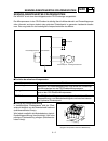
1 - 6 gen info checking of connection ec1c0001 checking of connection dealing with stains, rust, moisture, etc. On the connector. 1. Disconnect: ● connector 2. Dry each terminal with an air blower. 3. Connect and disconnect the connector two or three times. 4. Pull the lead to check that it will not...
Page 37: Gen
Gen info anschlÜsse prÜfen die steckverbinder auf oxidation, rost, feuchtigkeit usw. Prüfen. 1. Lösen: ● steckverbinder 2. Die einzelnen anschlußklem- men mit druckluft trockenbla- sen. 3. Den steckverbinder mehr- mals aufstekken und wieder abziehen. 4. Die einzelnen steckverbinder- kabel auf festsi...
Page 38: Gen
Gen info 1 - 7 ec140001 special tools the proper special tools are necessary for complete and accurate tune-up and assembly. Using the correct special tool will help prevent damage caused by the use of improper tools or improvised techniques. The shape and part number used for the special tool diffe...
Page 39: Gen
Gen info 1 - 8 special tools ym-01442, 90890-01442 fork seal driver this tool is used when install the fork oil seal. Ym-01442 90890-01442 ys-1880-a, 90890-01701 sheave holder this tool is used for when loosening or tightening the flywheel magneto securing nut. Ys-1880-a 90890-01701 yu-3112-c, 90890...
Page 40: Gen
Gen info 1 - 9 special tools ym-04142, 90890-04142 rotor puller this tool is used to remove the flywheel magneto. Ym-04142 90890-04142 ym-34487 90890-06754 dynamic spark tester ignition checker this instrument is necessary for checking the ignition system components. Ym-34487 90890-06754 acc-quick-g...
Page 41: Gen
Gen info outils speciaux les outils spéciaux appropriés sont indispensables pour pouvoir effectuer un assemblage et une mise au point complets et précis. L’utilisation des outils spéciaux corrects permettra d’éviter les endommagements dus à l’emploi d’outils impropres et aux techniques improvisées e...
Page 42: Gen
Gen info ym-01442, 90890-01442 outil d’insertion de joint de fourche cet outil est utilisé pour monter les bagues d’étanchéité de fourche. Ym-01442 90890-01442 ys-1880-a, 90890-01701 clé à sangle cet outil permet de desserrer et de resserrer l’écrou de fixation du volant magnétique. Ys-1880-a 90890-...
Page 43: Gen
Gen info ym-04142, 90890-04142 extracteur de rotor cet outil doit être utilisé pour la dépose du volant magnéti- que. Ym-04142 90890-04142 ym-34487 90890-06754 testeur d’étincelle dynamique contrôleur d’allumage ce testeur est nécessaire pour contrôler les composants du système d’allumage. Ym-34487 ...
Page 44: Gen
Gen info spezialwerkzeuge die folgenden spezialwerkzeuge sind für korrekte und vollständige einstell- und montagearbeiten unerläßlich. Durch die verwendung dieser werkzeuge können beschädigungen vermieden wer- den, die beim gebrauch ungeeigneter hilfsmittel oder improvisierter techniken entstehen kö...
Page 45: Gen
Gen info ym-01442, 90890-01442 gabeldichtring-treiber zum einbau der gabeldichtringe ym-01442 90890-01442 ys-1880-a, 90890-01701 kupplungskorb-halter zum halten des kupplungskorbes. Ys-1880-a 90890-01701 yu-3112-c, 90890-03112 taschen-multimeter zur prüfung und messung der elektrischen systeme yu-31...
Page 46: Gen
Gen info ym-04142, 90890-04142 rotorzieher zum ausbau des schwungradmagnetzünder-rotors ym-04142 90890-04142 ym-34487 90890-06754 zündfunkenstreckentester zündprüfer zur Überprüfung der zündanlage ym-34487 90890-06754 acc-quick-gs-kt 90890-85505 quick gasket ® yamaha-dichtmasse nr. 1215 zum abdichte...
Page 47: Gen
Gen info herramientas especiales las herramientas especiales apropiadas son indispensables para realizar un montaje y puesta a punto precisos. El empleo de herramientas especiales correctas ayudará a evitar daños provocados por el uso de herramientas inadecuadas o métodos inapropiados. La forma y el...
Page 48: Gen
Gen info ym-01442, 90890-01442 montador de retenes de la horquilla esta herramienta se utiliza cuando se instala el retén de aceite de la horquilla. Ym-01442 90890-01442 ys-1880-a, 90890-01701 soporte de roldana esta herramienta se utiliza cuando se afloja o aprieta la tuerca de sujeción del magneto...
Page 49: Gen
Gen info ym-04142, 90890-04142 extractor del rotor esta herramienta se utiliza para extraer el magneto del volante. Ym-04142 90890-04142 ym-34487 90890-06754 tester de bujías dinámico comprobador de encendido este instrumento se utiliza para comprobar los componen- tes del sistema de encendido. Ym-3...
Page 50: Gen
1 - 10 gen info control functions ec150000 control functions main switch functions of the respective switch positions are as follows: on: the engine can be started only at this position. Off: all electrical circuits are switched off. Main switch indicator light the main switch 1 is equipped with an ...
Page 51: Gen
Gen info fonctions des commandes steuerfunktionen funciones de control steuerfunktionen zÜndschalter die funktionen der einzelnen schalterpositionen sind wie folgt: on: der motor kann nur in dieser position gestartet werden. Off: alle elektrischen schaltkreise sind deaktiviert. Zündschalter-anzeigel...
Page 52: Gen
1 - 11 gen info control functions ec152000 clutch lever the clutch lever 1 is located on the left han- dlebar; it disengages or engages the clutch. Pull the clutch lever to the handlebar to disen- gage the clutch, and release the lever to engage the clutch. The lever should be pulled rapidly and rel...
Page 53: Gen
Gen info fonctions des commandes steuerfunktionen funciones de control kupplungshebel der kupplungshebel 1 befindet sich auf der linken seite des lenkers und dient zum ein- und auskuppeln. Zum ausrücken der kupplung den kupp- lungshebel zum lenkgriff ziehen; zum einrücken der kupplung den kupp- lung...
Page 54: Gen
1 - 12 gen info control functions ec157000 rear brake pedal the rear brake pedal 1 is located on the right side of the machine. Press down on the brake pedal to activate the rear brake. Fuel cock the fuel cock supplies fuel from the tank to carburetor and also filters the fuel. The fuel cock has thr...
Page 55: Gen
Gen info fonctions des commandes steuerfunktionen funciones de control fussbremshebel der fußbremshebel 1 zur betäti- gung der hinterradbremse befindet sich auf der rechten fahrzeugseite. Kraftstoffhahn der kraftstoffhahn leitet den kraft- stoff vom tank zum vergaser und fil- tert ihn gleichzeitig. ...
Page 56: Gen
1 - 13 gen info sidestand this sidestand 1 is used to support only the machine when standing or transporting it. Warning ● never apply additional force to the side- stand. ● hold up the sidestand before starting out. 1 ec15f000 valve joint this valve joint 1 prevents fuel from flowing out and is ins...
Page 57: Gen
Gen info fonctions des commandes steuerfunktionen funciones de control seitenstÄnder der seitenständer 1 ist nur zum tragen des maschinengewichts beim abstellen oder transportieren der maschine ausgelegt. Warnung ● niemals den seitenständer mit zusätzlichem gewicht belasten. ● vor dem losfahren sich...
Page 58: Gen
1 - 14 gen info fuel always use the recommended fuel as stated below. Also, be sure to use new gasoline the day of a race. Caution: use only unleaded gasoline. The use of leaded gasoline will cause severe damage to the engine internal parts such as valves, piston rings, and exhaust system, etc. Note...
Page 59: Gen
Gen info kraftstoff ausschließlich den empfohlenen kraftstoff verwenden. Für rennen fri- schen kraftstoff verwenden. Achtung: nur bleifreies benzin verwenden. Bei verwendung von verbleitem benzin werden schwere schäden an internen motorbauteilen wie ventilen, kolbenringen, auspuff- systemen usw. Ver...
Page 60: Gen
1 - 15 gen info starting and break-in starting and break-in warning never start or run the engine in a closed area. The exhaust fumes are poisonous; they can cause loss of consciousness and death in a very short time. Always operate the machine in a well-ventilated area. Caution: ● the carburetor on...
Page 61: Gen
Gen info mise en marche et rodage anlassen und einfahren arranque y rodaje anlassen und einfah- ren warnung den motor keinesfalls in geschlos- senen räumen anlassen und be- treiben. Abgase sind äußerst giftig und führen in kurzer zeit zu be- wußtlosigkeit und tod. Daher den motor nur an gut belüftet...
Page 62: Gen
1 - 16 gen info starting and break-in note: if the engine fails to start by pushing the start switch, release the switch, wait a few seconds, and then try again. Each starting attempt should be as short as possible to preserve the battery. Do not crank the engine more than 10 seconds on any one atte...
Page 63: Gen
Gen info mise en marche et rodage anlassen und einfahren arranque y rodaje hinweis: wenn der motor beim drücken des startschalters nicht anspringt, den schalter loslassen, einige sekunden warten, und erneut drücken. Jeder startversuch sollte so kurz wie mög- lich gehalten werden, um die batterie zu ...
Page 64: Gen
1 - 17 gen info starting and break-in starting a warm engine do not operate the cold starter knob and throt- tle. Pull the hot starter lever 1 and start the engine by pushing the start switch or by kick- ing the kickstarter forcefully with a firm stroke. As soon as the engine starts, release the hot...
Page 65: Gen
Gen info mise en marche et rodage anlassen und einfahren arranque y rodaje starten mit warmem motor zum anlassen des warmen motors weder den kaltstarterknopf drücken noch den gasdrehgriff öffnen, son- dern lediglich den heißstarterhebel 1 ziehen und den kickstarter kräftig durchtreten. Sobald der mo...
Page 66: Gen
1 - 18 gen info break-in procedures 1. Before starting the engine, fill the fuel tank with the fuel. 2. Perform the pre-operation checks on the machine. 3. Start and warm up the engine. Check the idle speed, and check the operation of the controls and the “engine stop” button. Then, restart the engi...
Page 67: Gen
Gen info einfahrvorschriften 1. Vor dem anlassen des motors volltanken. 2. Die “routinekontrolle vor fahrtbeginn” ausfüh- ren. 3. Den motor anlassen und warmlaufen lassen. Dabei die leerlaufdrehzahl überwachen und die funktion der bedie- nungselemente sowie des mo- torstoppschalters “engine stop” pr...
Page 68: Gen
Gen info 1 - 19 torque-check points torque-check points note: concerning the tightening torque, refer to “maintenance specifications” section in the chapter 2. Frame to rear frame fuel tank to frame silencer to rear frame frame to engine engine bracket to engine engine bracket to frame steering shaf...
Page 69: Gen
Gen info points de verification de couple de serrage points de verification de couple de serrage construction du cadre combinaison de selle et de réservoir système d’échappement montage du moteur direction de l’arbre de direction au guidon suspension avant de l’arbre de direction à la fourche avant ...
Page 70: Gen
Gen info hinweis: die anzugsmomente werden im abschnitt “wartungsdaten” im kapitel 2 aufge- führt. Anzugsmomente kontrollieren anzugsmomente kontrollieren rahmen sitzbank und kraftstofftank auspuff-system motoraufhängung lenkung lenkkopf und lenker radaufhängung vorn lenkkopf und teleskopgabel hinte...
Page 71: Gen
Gen info nota: para más información sobre la torsión de apriete, consulte el apartado “especificaciones de mantenimiento” del capÍtulo 2. Puntos de comprobaciÓn de la torsiÓn puntos de comprobaciÓn de la torsiÓn construcción del bastidor asiento y depósito combinado sistema de escape montura del mot...
Page 72: Gen
1 - 20 gen info cleaning and storage ec1b0000 cleaning and storage ec1b1000 cleaning frequent cleaning of your machine will enhance its appearance, maintain good overall performance, and extend the life of many com- ponents. 1. Before washing the machine, block off the end of the exhaust pipe to pre...
Page 73: Gen
Gen info nettoyage et rangement reinigung und stillegung limpieza y almacenamiento reinigung und stille- gung reinigung eine regelmäßige, gründliche wäsche sorgt nicht nur für gutes aussehen, sondern verbessert auch das allgemeine betriebsverhalten, reduziert verschleiß und bewirkt somit eine länger...
Page 74: Gen
1 - 21 gen info cleaning and storage 8. Automotive wax may be applied to all painted or chromed surfaces. Avoid com- bination cleaner-waxes, as they may con- tain abrasives. 9. After completing the above, start the engine and allow it to idle for several min- utes. Ec1b2001 storage if your machine i...
Page 75: Gen
Gen info nettoyage et rangement reinigung und stillegung limpieza y almacenamiento 8. Lack- und chromflächen kön- nen mit autowachs poliert werden. Kombinierte reiniger und polituren sind zu vermei- den, da sie oft scheuermittel enthalten, die den lack auf tank und verkleidungsteilen beschädigen wür...
Page 76: Spec
Spec 2 - 1 general specifications ec200000 specifications ec211000 general specifications model name: wr450fs (usa) wr450f (europe) wr450f(s) (cdn, aus, nz, za) model code number: 5tj5 (usa) 5tj6 (europe) 5tj7 (cdn, aus, nz, za) dimensions: overall length 2,171 mm (85.5 in) overall width 827 mm (32....
Page 77: Spec
Spec 2 - 2 general specifications oil capacity: engine oil periodic oil change 1.0 l (0.88 imp qt, 1.06 us qt) with oil filter replacement 1.1 l (0.97 imp qt, 1.16 us qt) total amount 1.2 l (1.06 imp qt, 1.27 us qt) coolant capacity (including all routes): 1.6 l (1.41 imp qt, 1.69 us qt) air filter:...
Page 78: Spec
Spec 2 - 3 general specifications brake: front brake type single disc brake operation right hand operation rear brake type single disc brake operation right foot operation suspension: front suspension telescopic fork rear suspension swingarm (link type monocross suspension) shock absorber: front sho...
Page 79: Spec
Spec 2 - 4 maintenance specifications maintenance specifications engine item standard limit cylinder head: warp limit ---- 0.05 mm (0.002 in) cylinder: bore size 95.00 ~ 95.01 mm (3.7402 ~ 3.7406 in) ---- out of round limit ---- 0.05 mm (0.002 in) camshaft: drive method chain drive (left) ---- camsh...
Page 80: Spec
Spec 2 - 5 maintenance specifications cam chain: cam chain type/no. Of links 98xrh2010-118m/118 ---- cam chain adjustment method automatic ---- valve, valve seat, valve guide: valve clearance (cold) in 0.10 ~ 0.15 mm (0.0039 ~ 0.0059 in) ---- ex 0.20 ~ 0.25 mm (0.0079 ~ 0.0098 in) ---- valve dimensi...
Page 81: Spec
Spec 2 - 6 maintenance specifications valve spring: free length in 37.03 mm (1.46 in) 36.03 mm (1.42 in) ex 37.68 mm (1.48 in) 36.68 mm (1.44 in) set length (valve closed) in 27.87 mm (1.10 in) ---- ex 27.38 mm (1.08 in) ---- compressed force (installed) in 111.3 ~ 127.9 n at 27.87 mm (11.3 ~ 13.0 k...
Page 82: Spec
Spec 2 - 7 maintenance specifications piston rings: top ring: type barrel ---- dimensions (b × t) 1.2 × 3.5 mm (0.05 × 0.14 in) ---- end gap (installed) 0.20 ~ 0.30 mm (0.008 ~ 0.012 in) 0.55 mm (0.022 in) side clearance (installed) 0.030 ~ 0.065 mm (0.0012 ~ 0.0026 in) 0.12 mm (0.005 in) 2nd ring: ...
Page 83: Spec
Spec 2 - 8 maintenance specifications clutch: friction plate thickness 2.92 ~ 3.08 mm (0.115 ~ 0.121 in) 2.8 mm (0.110 in) quantity 9 ---- clutch plate thickness 1.1 ~ 1.3 mm (0.043 ~ 0.051 in) ---- quantity 8 ---- warp limit ---- 0.1 mm (0.004 in) clutch spring free length 48.4 mm (1.91 in) 47.4 mm...
Page 84: Spec
Spec 2 - 9 maintenance specifications lubrication system: oil filter type paper type ---- oil pump type trochoid type ---- tip clearance “a” 0.12 mm or less (0.0047 in or less) 0.20 mm (0.008 in) tip clearance “b” 0.09 ~ 0.17 mm (0.0035 ~ 0.0067 in) 0.24 mm (0.009 in) side clearance 0.03 ~ 0.10 mm (...
Page 85: Spec
Spec 2 - 10 maintenance specifications item standard lubrication chart: pressure feed splashed scavenge oil strainer oil pan oil pump rotor 2 oil pump rotor 1 oil tank oil filter check ball cylinder head crank pin piston pin piston drive axle main axle transmission gears camshaft valve lifter.
Page 86: Spec
Spec 2 - 11 maintenance specifications part to be tightened thread size q’ty tightening torque nm m·kg ft·lb spark plug m10s × 1.0 1 13 1.3 9.4 camshaft cap m6 × 1.0 10 10 1.0 7.2 cylinder head blind plug screw m12 × 1.0 1 28 2.8 20 cylinder head (stud bolt) m6 × 1.0 2 7 0.7 5.1 m8 × 1.25 1 15 1.5 1...
Page 87: Spec
Spec 2 - 12 maintenance specifications note: - marked portion shall be checked for torque tightening after break-in or before each race. Note: *1: tighten the cylinder head bolts to 30 nm (3.0 m · kg, 22 ft · lb) in the proper tightening sequence, remove and retighten the cylinder head bolts to 20 n...
Page 88: Spec
Spec 2 - 13 maintenance specifications ec212201 chassis item standard limit steering system: steering bearing type taper roller bearing ---- front suspension: usa, cdn europe aus, nz, za front fork travel 300 mm (11.8 in) ← ← fork spring free length 460 mm (18.1 in) ← ← spring rate, std k = 4.51 n/m...
Page 89: Spec
Spec 2 - 14 maintenance specifications wheel: front wheel type spoke wheel ---- rear wheel type spoke wheel ---- front rim size/material 21 × 1.60/aluminum ---- rear rim size/material 18 × 2.15/aluminum ---- rim runout limit: radial ---- 2.0 mm (0.08 in) lateral ---- 2.0 mm (0.08 in) drive chain: ty...
Page 90: Spec
Spec 2 - 15 maintenance specifications note: 1. First, tighten the ring nut approximately 38 nm (3.8 m · kg, 27 ft · lb) by using the ring nut wrench, then loosen the ring nut one turn. 2. Retighten the ring nut 7 nm (0.7 m · kg, 5.1 ft · lb). Part to be tightened thread size q’ty tightening torque ...
Page 91: Spec
Spec 2 - 16 maintenance specifications part to be tightened thread size q’ty tightening torque nm m·kg ft·lb rear wheel axle and nut m20 × 1.5 1 125 12.5 90 driven sprocket and wheel hub m8 × 1.25 6 50 5.0 36 nipple (spoke) – 72 3 0.3 2.2 disc cover and rear brake caliper m6 × 1.0 2 7 0.7 5.1 protec...
Page 92: Spec
Spec 2 - 17 maintenance specifications note: - marked portion shall be checked for torque tightening after break-in or before each race. Meter cable holder and protector m5 × 0.8 2 4 0.4 2.9 headlight stay (lower) and under bracket m8 × 1.25 2 7 0.7 5.1 headlight body and headlight unit m6 × 1.0 2 7...
Page 93: Spec
Spec 2 - 18 maintenance specifications ec212300 electrical item standard limit ignition system: advancer type electrical ---- c.D.I.: pickup coil resistance (color) 248 ~ 372 Ω at 20 ˚c (68 ˚f) (white – red) ---- cdi unit-model/manufacturer 5tj50/yamaha (for usa) 5tj60/yamaha (except for usa) ---- -...
Page 94: Spec
Spec 2 - 19 maintenance specifications note: tighten the rotor nut to 65 nm (6.5 m · kg, 47 ft · lb), loosen and retighten the rotor nut to 65 nm (6.5 m · kg, 47 ft · lb). Starter relay: model/manufacturer 2768090-a/jideco ---- amperage rating 180 a ---- coil winding resistance 4.2 ~ 4.6 Ω at 20 ˚c ...
Page 95: Spec
Spec 2 - 20 ec220001 general torque specifications this chart specifies torque for standard fasten- ers with standard i.S.O. Pitch threads. Torque specifications for special components or assemblies are included in the applicable sec- tions of this book. To avoid warpage, tighten multi-fastener asse...
Page 96: Spec
2 - 1 caracteristiques generales spec caracteristiques caracteristiques generales nom de modèle: wr450fs (usa) wr450f (europe) wr450f(s) (cdn, aus, nz, za) numéro de code de modèle: 5tj5 (usa) 5tj6 (europe) 5tj7 (cdn, aus, nz, za) dimensions: longueur hors-tout 2.171 mm (85,5 in) largeur hors-tout 8...
Page 97: Spec
2 - 2 caracteristiques generales spec quantité d’huile: huile de moteur vidange périodique 1,0 l (0,88 imp qt, 1,06 us qt) avec remplacement du filtre à huile 1,1 l (0,97 imp qt, 1,16 us qt) quantité totale 1,2 l (1,06 imp qt, 1,27 us qt) capacité de liquide de refroidissement (toutes les tuyauterie...
Page 98: Spec
2 - 3 caracteristiques generales spec freins: type de frein avant frein à simple disque commande main droite type de frein arrière frein à simple disque commande pied droit suspension: suspension avant fourche télescopique suspension arrière bras oscillant (monocross de type biellette) amortisseurs:...
Page 99: Spec
2 - 4 caracteristiques d’entretien spec caracteristiques d’entretien moteur article standard limite culasse: limite de déformation ---- 0,05 mm (0,002 in) cylindre: alésage 95,00 à 95,01 mm (3,7402 à 3,7406 in) ---- limite d’ovalisation ---- 0,05 mm (0,002 in) arbre à cames: méthode d’entraînement t...
Page 100: Spec
2 - 5 caracteristiques d’entretien spec chaîne de distribution: type de chaîne de distribution/nbre de maillons 98xrh2010-118m/118 ---- méthode de réglage de la chaîne de distribution automatique ---- soupape, siège de soupape, guide de soupape: jeu de soupape (à froid) ad 0,10 à 0,15 mm (0,0039 à 0...
Page 101: Spec
2 - 6 caracteristiques d’entretien spec ressort de soupape: longueur libre ad 37,03 mm (1,46 in) 36,03 mm (1,42 in) ech 37,68 mm (1,48 in) 36,68 mm (1,44 in) longueur monté (soupape fermée) ad 27,87 mm (1,10 in) ---- ech 27,38 mm (1,08 in) ---- force compressée (installé) ad 111,3 à 127,9 n à 27,87 ...
Page 102: Spec
2 - 7 caracteristiques d’entretien spec segment: segment de feu: type cylindrique ---- dimensions (b × t) 1,2 × 3,5 mm (0,05 × 0,14 in) ---- ecartement des becs (monté) 0,20 à 0,30 mm (0,008 à 0,012 in) 0,55 mm (0,022 in) jeu latéral (monté) 0,030 à 0,065 mm (0,0012 à 0,0026 in) 0,12 mm (0,005 in) s...
Page 103: Spec
2 - 8 caracteristiques d’entretien spec embrayage: epaisseur de disque de friction 2,92 à 3,08 mm (0,115 à 0,121 in) 2,8 mm (0,110 in) quantité 9 ---- epaisseur de disque d’embrayage 1,1 à 1,3 mm (0,043 à 0,051 in) ---- quantité 8 ---- limite de déformation ---- 0,1 mm (0,004 in) longueur libre de r...
Page 104: Spec
2 - 9 caracteristiques d’entretien spec système de graissage: type de filtre à huile type de papier ---- type de pompe à huile trochoïde ---- jeu en bout “a” 0,12 mm ou moins (0,0047 in ou moins) 0,20 mm (0,008 in) jeu en bout “b” 0,09 à 0,17 mm (0,0035 à 0,0067 in) 0,24 mm (0,009 in) jeu latéral 0,...
Page 105: Spec
2 - 10 caracteristiques d’entretien spec article standard diagramme de graissage: graissage sous pression barbotage crépine à huile carter d’huile rotor de pompe à huile 1 rotor de pompe à huile 2 réservoir d’huile filtre à huile bille d’arrêt culasse maneton de bielle axe de piston piston arbre sec...
Page 106: Spec
2 - 11 caracteristiques d’entretien spec pièce à serrer taille de filetage qté couple de serrage nm m·kg ft·lb bougie m10s × 1,0 1 13 1,3 9,4 chapeau d’arbre à cames m6 × 1,0 10 10 1,0 7,2 vis de faux bouchon de culasse m12 × 1,0 1 28 2,8 20 culasse (boulon prisonnier) m6 × 1,0 2 7 0,7 5,1 m8 × 1,25...
Page 107: Spec
2 - 12 caracteristiques d’entretien spec n.B.: le couple de serrage des parties marquées doit être vérifié après le rodage ou avant chaque course. N.B.: *1: serrer les boulons de culasse à 30 nm (3,0 m · kg, 22 ft · lb) dans l’ordre, retirer et resserrer les boulons de culasse à 20 nm (2,0 m · kg, 1...
Page 108: Spec
2 - 13 caracteristiques d’entretien spec partie-cycle article standard limite direction: type de roulement de direction roulement à rouleaux conique ---- suspension avant: usa, cdn europe aus, nz, za débattement de fourche avant 300 mm (11,8 in) ← ← longueur libre de ressort de fourche 460 mm (18,1 ...
Page 109: Spec
2 - 14 caracteristiques d’entretien spec roue: type de roue avant roue à rayons ---- type de roue arrière roue à rayons ---- taille/matériau de jante avant 21 × 1,60/aluminum ---- taille/matériau de jante arrière 18 × 2,15/aluminum ---- limite de voile de jante: radial ---- 2,0 mm (0,08 in) latéral ...
Page 110: Spec
2 - 15 caracteristiques d’entretien spec n.B.: 1. Serrer d’abord l’écrou annulaire à environ 38 nm (3,8 m · kg, 27 ft · lb) en utilisant la clé pour écrou annu- laire puis le dévisser d’un tour. 2. Resserrer l’écrou annulaire à 7 nm (0,7 m · kg, 5,1 ft · lb). Pièce à serrer taille de filetage qté co...
Page 111: Spec
2 - 16 caracteristiques d’entretien spec pièce à serrer taille de filetage qté couple de serrage nm m·kg ft·lb axe de roue arrière et écrou m20 × 1,5 1 125 12,5 90 pignon mené et moyeu de roue m8 × 1,25 6 50 5,0 36 ecrou de rayon — 72 3 0,3 2,2 couvercle de disque et étrier de frein arrière m6 × 1,0...
Page 112: Spec
2 - 17 caracteristiques d’entretien spec n.B.: le couple de serrage des parties marquées doit être vérifié après le rodage ou avant chaque course. Support et protection du câble de compteur m5 × 0,8 2 4 0,4 2,9 montant de phare (inférieur) et support inférieur m8 × 1,25 2 7 0,7 5,1 bloc phare et pha...
Page 113: Spec
2 - 18 caracteristiques d’entretien spec partie electrique article standard limite système d’allumage: type de dispositif d’avance electrique ---- cdi: résistance de bobine d’excitation (couleur) 248 à 372 Ω à 20 ˚c (68 ˚f) (blanc – rouge) ---- modèle/fabricant du bloc cdi 5tj50/yamaha (pour les usa...
Page 114: Spec
2 - 19 caracteristiques d’entretien spec n.B.: serrer l’écrou du rotor à 65 nm (6,5 m · kg, 47 ft · lb), desserrer puis resserrer l’écrou du rotor à 65 nm (6,5 m · kg, 47 ft · lb). Relais du démarreur: modèle/fabricant 2768090-a/jideco ---- nombre d’ampères 180 a ---- résistance des spirales de la b...
Page 115: Spec
2 - 20 spec caracteristiques generales de couple ce tableau spécifie les couples de serrage des atta- ches standard avec filetage à pas i.S.O. Standard. Les spécifications de couple pour les composants ou ensembles spéciaux sont indiquées dans les sec- tions appropriées de ce manuel. Pour éviter tou...
Page 116: Spec
2 - 1 allgemeine technische daten spec technische daten allgemeine technische daten modellname: wr450fs (usa) wr450f (europa) wr450f(s) (cdn, aus, nz, za) modellcode: 5tj5 (usa) 5tj6 (europa) 5tj7 (cdn, aus, nz, za) abmessungen: gesamtlänge 2.171 mm (85,5 in) gesamtbreite 827 mm (32,6 in) gesamthöhe...
Page 117: Spec
2 - 2 allgemeine technische daten spec Ölmenge: füllmenge Ölwechsel ohne filterwechsel 1,0 l (0,88 imp qt, 1,06 us qt) Ölwechsel mit filterwechsel 1,1 l (0,97 imp qt, 1,16 us qt) gesamtmenge 1,2 l (1,06 imp qt, 1,27 us qt) kühlsystem-fassungsvermögen (gesamtmenge): 1,6 l (1,41 imp qt, 1,69 us qt) lu...
Page 118: Spec
2 - 3 allgemeine technische daten spec bremsanlage: vorn bauart einscheibenbremse betätigung handbremshebel (rechts) hinten bauart einscheibenbremse betätigung fußbremshebel (rechts) radaufhängung: vorn teleskopgabel hinten monocross-schwinge federelemente: vorn hydraulisch gedämpfte teleskopgabel m...
Page 119: Spec
2 - 4 wartungsdaten spec wartungsdaten motor bezeichnung spezifikation grenzwert zylinderkopf: max. Verzug ---- 0,05 mm (0,002 in) zylinder: bohrungsdurchmesser 95,00–95,01 mm (3,7402–3,7406 in) ---- max. Ovalität ---- 0,05 mm (0,002 in) nockenwelle: antrieb steuerkette (links) ---- nockenwellenlage...
Page 120: Spec
2 - 5 wartungsdaten spec steuerkette: typ/gliederzahl 98xrh2010-118m/118 ---- kettenspannung automatisch ---- ventile, ventilsitze, ventilführungen: ventilspiel (kalt) einlaß 0,10–0,15 mm (0,0039–0,0059 in) ---- auslaß 0,20–0,25 mm (0,0079–0,0098 in) ---- ventilabmessungen ventiltellerdurchmesser “a...
Page 121: Spec
2 - 6 wartungsdaten spec ventilfeder: ungespannte länge einlaß 37,03 mm (1,46 in) 36,03 mm (1,42 in) auslaß 37,68 mm (1,48 in) 36,68 mm (1,44 in) einbaulänge (ventil geschlossen) einlaß 27,87 mm (1,10 in) ---- auslaß 27,38 mm (1,08 in) ---- druckkraft (eingebaut) einlaß 111,3–127,9 n bei 27,87 mm (1...
Page 122: Spec
2 - 7 wartungsdaten spec kolbenringe: 1. Kompressionsring (topring) ausführung abgerundet ---- abmessungen (b × t) 1,2 × 3,5 mm (0,05 × 0,14 in) ---- stoßspiel (eingebaut) 0,20–0,30 mm (0,008–0,012 in) 0,55 mm (0,022 in) ringnutspiel (eingebaut) 0,030–0,065 mm (0,0012–0,0026 in) 0,12 mm (0,005 in) 2...
Page 123: Spec
2 - 8 wartungsdaten spec kupplung: reibscheiben stärke 2,92–3,08 mm (0,115–0,121 in) 2,8 mm (0,110 in) anzahl 9 ---- kupplungsscheiben stärke 1,1–1,3 mm (0,043–0,051 in) ---- anzahl 8 ---- verzug ---- 0,1 mm (0,004 in) kupplungsfeder ungesp. Länge 48,4 mm (1,91 in) 47,4 mm (1,87 in) anzahl 6 ---- ku...
Page 124: Spec
2 - 9 wartungsdaten spec schmiersystem: Ölfilter papiertyp ---- Ölpumpe rotorpumpe ---- radialspiel “a” 0,12 mm oder weniger (0,0047 in oder weniger) 0,20 mm (0,008 in) radialspiel “b” 0,09–0,17 mm (0,0035–0,0067 in) 0,24 mm (0,009 in) axialspiel 0,03–0,10 mm (0,0012–0,0039 in) 0,17 mm (0,007 in) Üb...
Page 125: Spec
2 - 10 wartungsdaten spec bezeichnung spezifikation Ölkreislauf-schaubild druckumlaufschmierung spritzschmierung Ölsieb Ölwanne Ölpumpenrotor 1 Ölpumpenrotor 2 Öltank Ölfilter rückschlagventil zylinderkopf kurbelwellenzapfen kolbenbolzen kolben getriebe- ausgangswelle getriebe- eingangswelle getrieb...
Page 126: Spec
2 - 11 wartungsdaten spec bauteil gewinde anz. Anzugs-moment nm m·kg ft·lb zündkerze m10s × 1,0 1 13 1,3 9,4 zündkerzenstecker m6 × 1,0 10 10 1,0 7,2 zylinderkopf-blindstopfenschraube m12 × 1,0 1 28 2,8 20 zylinderkopf (stiftschraube) m6 × 1,0 2 7 0,7 5,1 m8 × 1,25 1 15 1,5 11 (schraube) m10 × 1,25 ...
Page 127: Spec
2 - 12 wartungsdaten spec hinweis: : sicherstellen, daß diese teile nach dem einfahren und vor jedem rennen vorschriftsmäßig festgezogen sind. Hinweis: *1: die zylinderkopfschrauben auf 30 nm (3,0 m · kg, 22 ft · lb) in der richtigen anzugsreihenfolge festziehen, ausbauen und dann die zylinderkopfsc...
Page 128: Spec
2 - 13 wartungsdaten spec fahrwerkl bauteil spezifikation grenzwert lenkung: lenkkopflager kegelrollenlager ---- federelement vorn: usa, cdn europa aus, nz, za federweg 300 mm (11,8 in) ← ← gabelfeder, ungespannte länge 460 mm (18,1 in) ← ← standard-federrate k = 4,51 n/mm (0,46 kg/mm, 25,8 lb/in) k...
Page 129: Spec
2 - 14 wartungsdaten spec räder: bauart: vorderrad speichenrad ---- hinterrad speichenrad ---- felgendimension/-material vorderrad 21 × 1,60/aluminium ---- hinterrad 18 × 2,15/aluminium ---- max. Felgenschlag höhenschlag ---- 2,0 mm (0,08 in) seitenschlag ---- 2,0 mm (0,08 in) antriebskette: typ (he...
Page 130: Spec
2 - 15 wartungsdaten spec hinweis: 1. Die ringmutter mit ca. 38 nm (3,8 m · kg, 27 ft · lb) festziehen, dann um eine drehung lösen. 2. Die ringmutter schließlich mit 7 nm (0,7 m · kg, 5,1 ft · lb) festziehen. Bauteil gewinde anz. Anzugsmoment nm m·kg ft·lb obere gabelbrücke und standrohr m8 × 1,25 4...
Page 131: Spec
2 - 16 wartungsdaten spec bauteil gewinde anz. Anzugsmoment nm m·kg ft·lb hinterachse und mutter m20 × 1,5 1 125 12,5 90 antriebskettenrad und radnabe m8 × 1,25 6 50 5,0 36 speichen-nippel — 72 3 0,3 2,2 bremsscheiben-abdeckung und bremssattel hinten m6 × 1,0 2 7 0,7 5,1 bremssattel-schutz und brems...
Page 132: Spec
2 - 17 wartungsdaten spec hinweis: : sicherstellen, daß diese teile nach dem einfahren und vor jedem rennen vorschriftsmäßig festgezogen sind. Instrumentenkabelhalter und schutz m5 × 0,8 2 4 0,4 2,9 scheinwerferstrebe (unten) und unterbügel m8 × 1,25 2 7 0,7 5,1 scheinwerfergehäuse und scheinwerfere...
Page 133: Spec
2 - 18 wartungsdaten spec elektrische anlage bauteil spezifikation grenzwert zündsystem: zündversteller elektrisch ---- cdi: impulsgeber-widerstand (farbe) 248–372 Ω bei 20 ˚c (68 ˚f) (weiß – rot) ---- cdi-zündbox: typ (hersteller) 5tj50/yamaha (nur usa) 5tj60/yamaha (nicht usa) ---- ---- zündspule:...
Page 134: Spec
2 - 19 wartungsdaten spec hinweis: die rotormutter auf 65 nm (6,5 m · kg, 47 ft · lb) festziehen, lösen und dann erneut auf 65 nm (6,5 m · kg, 47 ft · lb) festziehen. Starterrelais: modell/hersteller 2768090-a/jideco ---- stromstärke 180 a ---- spulenwicklungswiderstand 4,2–4,6 Ω bei 20 ˚c (68 ˚f) -...
Page 135: Spec
2 - 20 spec allgemeine anzugsmomente aus der folgenden tabelle sind die anzugsmo- mente für normale schraubverbindungen mit iso-normgewinde ersichtlich. Anzugsmomente für spezielle verschraubungen und bauteile wer- den in jedem abschnitt dieser anleitung geson- dert aufgeführt. Um ein verziehen der ...
Page 136: Spec
2 - 1 spec especificaciones generales especificaciones especificaciones generales nombre del modelo: wr450fs (usa) wr450f (europe) wr450f(s) (cdn, aus, nz, za) número del código del modelo: 5tj5 (usa) 5tj6 (europe) 5tj7 (cdn, aus, nz, za) dimensiones: longitud total 2.171 mm (85,5 in) anchura total ...
Page 137: Spec
2 - 2 spec especificaciones generales capacidad de aceite: aceite de motor cambio de aceite periódico 1,0 l (0,88 imp qt, 1,06 us qt) con sustitución del filtro de aceite 1,1 l (0,97 imp qt, 1,16 us qt) cantidad total 1,2 l (1,06 imp qt, 1,27 us qt) capacidad de refrigerante (incluyendo todas las ru...
Page 138: Spec
2 - 3 spec especificaciones generales neumático: tipo con cámara tamaño (delantero) 80/100-21 51m (usa, cdn, za) 90/90-21 54r (europe, aus, nz) tamaño (trasero) 110/100-18 64m (usa, cdn, za) 130/90-18 69r (europe, aus, nz) presión del neumático (delantero y trasero) 100 kpa (1,0 kgf/cm 2 , 15 psi) f...
Page 139: Spec
2 - 4 spec especificaciones de mantenimiento especificaciones de mantenimiento motor Ítem estándar límite culata: límite de alabeo ---- 0,05 mm (0,002 in) cilindro: tamaño del diámetro 95,00 ~ 95,01 mm (3,7402 ~ 3,7406 in) ---- límite de ovalización ---- 0,05 mm (0,002 in) Árbol de levas: método de ...
Page 140: Spec
2 - 5 spec especificaciones de mantenimiento cadena de la leva: tipo de cadena de la leva/n˚ de eslabones 98xrh2010-118m/118 ---- método de ajuste de la cadena de la leva automático ---- válvula, asiento de la válvula, guía de válvula: juego de la válvula (en frío) admisiÓn 0,10 ~ 0,15 mm (0,0039 ~ ...
Page 141: Spec
2 - 6 spec especificaciones de mantenimiento muelles de la válvula: longitud libre admisiÓn 37,03 mm (1,46 in) 36,03 mm (1,42 in) escape 37,68 mm (1,48 in) 36,68 mm (1,44 in) longitud comprimida (válvula cerrada) admisiÓn 27,87 mm (1,10 in) ---- escape 27,38 mm (1,08 in) ---- fuerza comprimida (mont...
Page 142: Spec
2 - 7 spec especificaciones de mantenimiento aros del pistón: aro superior: tipo barril ---- dimensiones (b × t) 1,2 × 3,5 mm (0,05 × 0,14 in) ---- separación entre puntas (montado) 0,20 ~ 0,30 mm (0,008 ~ 0,012 in) 0,55 mm (0,022 in) holgura lateral (montado) 0,030 ~ 0,065 mm (0,0012 ~ 0,0026 in) 0...
Page 143: Spec
2 - 8 spec especificaciones de mantenimiento embrague: grosor del plato de fricción 2,92 ~ 3,08 mm (0,115 ~ 0,121 in) 2,8 mm (0,110 in) cantidad 9 ---- grosor del disco de embrague 1,1 ~ 1,3 mm (0,043 ~ 0,051 in) ---- cantidad 8 ---- límite de alabeo ---- 0,1 mm (0,004 in) longitud libre de los muel...
Page 144: Spec
2 - 9 spec especificaciones de mantenimiento sistema de lubricación: tipo de filtro de aceite tipo papel ---- tipo de bomba de aceite tipo trocoidal ---- juego axial “a” 0,12 mm o menos (0,0047 in o menos) 0,20 mm (0,008 in) juego axial “b” 0,09 ~ 0,17 mm (0,0035 ~ 0,0067 in) 0,24 mm (0,009 in) holg...
Page 145: Spec
2 - 10 spec especificaciones de mantenimiento Ítem estándar tabla de lubricación: alimentación a presión eliminación de salpicaduras cesta de aspiración de aceite cárter de aceite rotor 1 de la bomba de aceite rotor 2 de la bomba de aceite depósito de aceite filtro de aceite bola de comprobación cul...
Page 146: Spec
2 - 11 spec especificaciones de mantenimiento pieza a apretar tamaño de la rosca cant. Par de apriete nm m·kg ft·lb bujía m10s × 1,0 1 13 1,3 9,4 tapa del árbol de levas m6 × 1,0 10 10 1,0 7,2 tornillo del tapón ciego de la culata m12 × 1,0 1 28 2,8 20 culata (espárrago) m6 × 1,0 2 7 0,7 5,1 m8 × 1,...
Page 147: Spec
2 - 12 spec especificaciones de mantenimiento nota: debe comprobar el par de apriete de la parte marcada después del rodaje o antes de cada carrera. Nota: *1: apriete los pernos de la culata a 30 nm (3,0 m · kg, 22 ft · lb) en la secuencia de apriete apropiada, quite y vuelva a apretar los pernos de...
Page 148: Spec
2 - 13 spec especificaciones de mantenimiento chasis Ítem estándar límite sistema de dirección: tipo de cojinete de dirección cojinete de rodillos cónicos ---- suspensión delantera: usa, cdn europe aus, nz, za recorrido de la horquilla delantera 300 mm (11,8 in) ← ← longitud libre del muelle de la h...
Page 149: Spec
2 - 14 spec especificaciones de mantenimiento rueda: tipo de rueda delantera radio de la rueda ---- tipo de rueda trasera radio de la rueda ---- tamaño de la llanta delantera/material 21 × 1,60/aluminio ---- tamaño de la llanta trasera/material 18 × 2,15/aluminio ---- límite de excentricidad de la l...
Page 150: Spec
2 - 15 spec especificaciones de mantenimiento nota: 1. En primer lugar, apriete la tuerca anular a 38 nm (3,8 m · kg, 27 ft · lb) aproximadamente utilizando la llave dinamométrica y, a continuación afloje la tuerca una vuelta. 2. Vuelva a apretar la tuerca anular a 7 nm (0,7 m · kg, 5,1 ft · lb). Pi...
Page 151: Spec
2 - 16 spec especificaciones de mantenimiento pieza a apretar tamaño de la rosca cant. Par de apriete nm m·kg ft·lb eje de la rueda trasera y tuerca m20 × 1,5 1 125 12,5 90 piñón de transmisión y rodete de la rueda m8 × 1,25 6 50 5,0 36 engrasador (radio) — 72 3 0,3 2,2 cubierta del disco y pinza de...
Page 152: Spec
2 - 17 spec especificaciones de mantenimiento nota: debe comprobar el par de apriete de la parte marcada después del rodaje o antes de cada carrera. Soporte del cable del medidor y protector m5 × 0,8 2 4 0,4 2,9 soporte del faro (inferior) y ménsula inferior m8 × 1,25 2 7 0,7 5,1 cuerpo del faro y u...
Page 153: Spec
2 - 18 spec especificaciones de mantenimiento sistema elÉctrico Ítem estándar límite sistema de encendido: tipo de dispositivo de avance sistema eléctrico ---- cdi: resistencia de la bobina de aceleración rápida (color) 248 ~ 372 Ω a 20 ˚c (68 ˚f) (blanco – rojo) ---- modelo de la unidad cdi/fabrica...
Page 154: Spec
2 - 19 spec especificaciones de mantenimiento nota: apriete la tuerca del rotor a 65 nm (6,5 m · kg, 47 ft · lb), afloje y vuelva a apretar la tuerca del rotor a 65 nm (6,5 m · kg, 47 ft · lb). Relé del arrancador: modelo/fabricante 2768090-a/jideco ---- amperaje nominal 180 a ---- resistencia del b...
Page 155: Spec
2 - 20 spec especificaciones de apriete generales esta tabla especifica el apriete de los elementos de fijación provistos de roscas i.S.O. Estándar. Las especificaciones de apriete para los componentes o conjuntos especiales se incluyen en las secciones correspondientes del manual. Para evitar alabe...
Page 156: Spec
2 - 21 spec lubrication diagrams lubrication diagrams 1 oil delivery pipe 2 intake camshaft 3 exhaust camshaft 4 oil cleaner element 5 oil pump 6 main axle 7 drive axle 7 6 5 4 3 2 1 4 5 a - a d - d g g d d a a.
Page 157: Spec
Spec 2 - 21 schemas de graissage schmiersystem-schaubilder diagramas de lubricaciÓn schmiersystem- schaubilder 1 Ölzufuhrleitung 2 einlaß-nockenwelle 3 auslaß-nockenwelle 4 Ölfiltereinsatz 5 Ölpumpe 6 getriebe-eingangswelle 7 getriebe-ausgangswelle schemas de grais- sage 1 tuyau d’arrivée d’huile 2 ...
Page 158: Spec
2 - 22 spec lubrication diagrams 1 camshaft 2 connecting rod 3 oil cleaner element 4 crankshaft 5 main axle 6 drive axle 7 oil delivery pipe 1 2 3 4 5 6 7.
Page 159: Spec
Spec 2 - 22 schemas de graissage schmiersystem-schaubilder diagramas de lubricaciÓn 1 nockenwelle 2 pleuel 3 Ölfiltereinsatz 4 kurbelwelle 5 getriebe-eingangswelle 6 getriebe-ausgangswelle 7 Ölzufuhrleitung 1 arbre à cames 2 bielle 3 element du filtre à air 4 vilebrequin 5 arbre primaire 6 arbre sec...
Page 160: Spec
2 - 23 spec cable routing diagram ec240000 cable routing diagram 1 fuel tank breather hose 2 clamp 3 diode 4 wire harness 5 hot starter cable 6 negative battery lead 7 starter motor lead 8 tps (throttle position sen- sor) lead 9 neutral switch lead 0 oil hose a hose holder b radiator hose 4 c cylind...
Page 161: Spec
Spec 2 - 23 cheminement des cables kabelfÜhrung diagrama de ruta de cables kabelfÜhrung 1 kraftstofftank-lüfterschlauch 2 klammer 3 diode 4 kabelbaum 5 heißstarter-seilzug 6 minus-batteriekabel 7 startermotorkabel 8 tps (drosselpositionssensor) leitung 9 leerlaufschalterleitung 0 Ölschlauch a schlau...
Page 162: Spec
2 - 24 spec cable routing diagram Ï fasten the wire harness, tps lead (in the wire harness), starter motor lead and negative battery lead to the frame with a plastic locking tie and cut off the tie end. Ì make sure that the tps cou- pler does not go out the chas- sis. Ó fasten the tps lead to the fr...
Page 163: Spec
Spec 2 - 24 cheminement des cables kabelfÜhrung diagrama de ruta de cables Ï den kabelbaum, die tps-leitung (im kabelbaum) die startermotorleitung und das minus-batteriekabel am rah- men mit einem plastiksperrband befe- stigen und das bandende abschnei- den. Ì sicherstellen, daß der tps-leitungs- st...
Page 164: Spec
2 - 25 spec cable routing diagram 1 hot starter cable 2 clutch cable 3 throttle cable (return) 4 throttle cable (pull) 5 ignition coil 6 negative battery lead 7 starter motor lead 8 coolant reservoir tank breather hose 9 rectifier/regulator 0 cable holder a coolant reservoir hose b rectifier/regulat...
Page 165: Spec
Spec 2 - 25 cheminement des cables kabelfÜhrung diagrama de ruta de cables 1 heißstarter-seilzug 2 kupplungsseilzug 3 gasseilzug (rückzug) 4 gasseilzug (zug) 5 zündspule 6 minus-batteriekabel 7 startermotorkabel 8 kühlmittelausgleichsbehälter-lüf- tungsschlauch 9 gleichrichter/regulierer 0 seilzugha...
Page 166: Spec
2 - 26 spec cable routing diagram 1 master cylinder 2 brake hose holder 3 brake hose Å install the brake hose so that its pipe portion directs as shown and lightly touches the projection on the caliper. ı pass the brake hose into the brake hose holders. Ç if the brake hose contacts the spring (rear ...
Page 167: Spec
Spec 2 - 26 1 hauptzylinder 2 bremsschlauchhalter 3 bremsschlauch Å den bremsschlauch so einbauen, daß der röhrenteil wie gezeigt liegt und leicht den vorsprung am brems- sattel berührt. ı den bremsschlauch durch die brems- schlauchhalter führen. Ç wenn er bremsschlauch die feder berührt (hinterer s...
Page 168: Spec
2 - 27 spec cable routing diagram 1 starter motor lead 2 negative battery lead 3 wire harness 4 clamp 5 taillight lead 6 coolant reservoir tank breather hose 7 coolant reservoir hose 8 positive battery lead 9 starting circuit cut-off relay 0 battery Å position the starter motor lead, negative batter...
Page 169: Spec
Spec 2 - 27 1 startermotorleitung 2 minus-batteriekabel 3 kabelbaum 4 klammer 5 heckleuchtenleitung 6 kühlmittelausgleichsbehälter-lüf- tungsschlauch 7 kühlmittelausgleichsbehälter- schlauch 8 plus-batteriekabel 9 starterkreis-unterbrecherrelais 0 batterie Å die startermotorleitung, das minus- batte...
Page 170: Spec
2 - 28 spec cable routing diagram 1 throttle cable 2 clamp 3 brake hose 4 hot starter cable 5 clutch cable 6 hose guide 7 clutch switch lead 8 “engine stop” button lead 9 trip meter cable 0 main switch lead a trip meter b main switch c start switch lead Å fasten the start switch lead to the handleba...
Page 171: Spec
Spec 2 - 28 1 gasseilzug 2 klammer 3 bremsschlauch 4 heißstarter-seilzug 5 kupplungsseilzug 6 schlauchführung 7 kupplungsschalterleitung 8 motorstoppschalter-kabel 9 tageskilometerzählerkabel 0 zündschalterleitung a tageskilometerzähler b hauptschalter c startschalterleitung Å die startschalterleitu...
Page 172: Insp
3 - 1 insp adj maintenance intervals ec300000 regular inspection and adjustments maintenance intervals the following schedule is intended as a general guide to maintenance and lubrication. Bear in mind that such factors as weather, terrain, geographical location, and individual usage will alter the ...
Page 173: Insp
3 - 2 insp adj maintenance intervals shift fork, shift cam, guide bar inspect ● inspect wear rotor nut retighten ● ● muffler inspect and retighten clean replace ● ● ● ● * whichever comes first *spark arrester clean (every six months) ● crank inspect and clean ● ● carburetor inspect, adjust and clean...
Page 174: Insp
3 - 3 insp adj maintenance intervals * marked: for usa front forks inspect and adjust replace oil replace oil seal ● ● ● ● ● suspension oil “01” front fork oil seal and dust seal clean and lube ● ● lithium base grease rear shock absorber inspect and adjust lube retighten ● ● ● ● ● (after rain ride) ...
Page 175: Insp
Insp adj programme d’entretien controles et reglages courants programme d’entretien le programme suivant est destiné à servir de guide général pour l’entretien et la lubrification. Garder à l’esprit que le temps, le terrain, la situation géographique et l’emploi que l’on fait de sa machine ont une g...
Page 176: Insp
Insp adj programme d’entretien ecrou du rotor resserrer ● ● pot d’echappement contrôler et resserrer nettoyer changer ● ● ● ● * a la première des deux échéances * pare-etincelles nettoyer (tous les six mois) ● vilebrequin contrôler et nettoyer ● ● carburateur contrôler, régler et nettoyer ● ● bougie...
Page 177: Insp
Insp adj programme d’entretien astérique* : usa fourche avant contrôler et régler changer l’huile changer la bague d’étanchéité ● ● ● ● ● huile de suspension “01” bague d’etancheite et joint antipoussiere de fourche avant nettoyer et lubrifier ● ● graisse à base de lithium amortisseur arriere contrô...
Page 178: Insp
Insp adj wartungsintervalle und schmierdienst regelmÄssige inspektion und einstellarbeiten wartungsintervalle und schmierdienst die hier empfohlenen zeitabstände für wartung und schmierung sollten jedoch lediglich als richt- werte für den normalbetrieb angesehen werden. Je nach wetterbedingungen, be...
Page 179: Insp
Insp adj wartungsintervalle und schmierdienst rotormutter nachziehen ● ● schalldÄmpfer prüfen und reinigen reinigen erneuern ● ● ● ● *was zuerst eintrifft * funkenfÄnger reinigen (alle sechs monate) ● kurbelwelle prüfen und reinigen ● ● vergaser prüfen, einstellen und reinigen ● ● zÜndkerze prüfen u...
Page 180: Insp
Insp adj wartungsintervalle und schmierdienst * markiert: für usa teleskopgabel prüfen und einstellen Öl wechseln dichtringe wechseln ● ● ● ● ● teleskopgabelöl “01” ver- wenden. Gabeldichtring und staubman- schette reinigen und schmieren ● ● lithiumfett verwenden. Federbein prüfen und einstellen sch...
Page 181: Insp
Insp adj intervalos de mantenimiento ajustes e inspecciÓn regulares intervalos de mantenimiento el siguiente programa está diseñado como una guía general de los procesos de mantenimiento y lubricación. Tenga en cuenta que factores como el tiempo, el terreno, la ubicación geográfica y el uso individu...
Page 182: Insp
Insp adj intervalos de mantenimiento tuerca del rotor ajustar nuevamente ● ● silenciador inspeccionar y limpiar limpiar reemplazar ● ● ● ● *lo que suceda primero. * parachispas limpiar (cada seis meses) ● cÁrter inspeccionar y limpiar ● ● carburador inspeccionar, ajustar y limpiar ● ● bujÍa inspecci...
Page 183: Insp
Insp adj intervalos de mantenimiento marcado con *: para usa horquillas delanteras inspeccionar y ajustar reemplazar el aceite reemplazar el retén de aceite ● ● ● ● ● aceite de suspensión “01” retÉn de aceite de la horqui- lla delantera y guardapolvos limpiar y lubricar ● ● grasa con base de litio a...
Page 184: Insp
3 - 4 insp adj pre-operation inspection and maintenance ec320000 pre-operation inspection and maintenance before riding for break-in operation, practice or a race, make sure the machine is in good operating condition. Before using this machine, check the following points. General inspection and main...
Page 185: Insp
Insp adj controle et entretien avant utilisation controle et entretien avant utilisation avant la conduite pour le rodage, l’entraînement ou une course, s’assurer que la machine est en bon état de marche. Avant d’utiliser cette machine, contrôler les points suivants. Controle general et entretien pa...
Page 186: Insp
Insp adj wartungs- und einstellarbeiten vor fahrtbeginn wartungs- und einstellarbeiten vor fahrtbeginn der betriebszustand der maschine muß sowohl vor dem einfahren als auch vor jeder Übungs- und rennfahrt überprüft werden. Vor fahrtbeginn neben einer gewissenhaften sichtkontrolle folgende punkte pr...
Page 187: Insp
Insp adj inspecciÓn y mantenimiento previos a la conducciÓn inspecciÓn y mantenimiento previos a la conducciÓn antes de conducir el vehículo para llevar a cabo el rodaje, practicar o participar en una carrera, asegúrese de que el vehículo esté en buenas condiciones de funcionamiento. Antes de utiliz...
Page 188: Insp
3 - 5 insp adj ec350000 engine coolant level inspection warning do not remove the radiator cap 1, drain bolt and hoses when the engine and radia- tor are hot. Scalding hot fluid and steam may be blown out under pressure, which could cause serious injury. When the engine has cooled, place a thick tow...
Page 189: Insp
Insp adj motor kÜhlflÜssigkeitstand kontrollieren warnung der heiße kühler steht unter druck. Daher niemals den kühlerverschluß- deckel 1, die ablaßschraube oder kühlsystemschläuche bei heißem motor abnehmen, denn austreten- der dampf und heiße kühlflüssig- keit könnten ernsthafte verbrühun- gen ver...
Page 190: Insp
3 - 6 insp adj coolant replacement caution: take care so that coolant does not splash on painted surfaces. If it splashes, wash it away with water. 1. Place a container under the engine. 2. Remove: ● seat refer to “seat, fuel tank and side covers” section in the chap- ter 4. 3. Disconnect: ● coolant...
Page 191: Insp
Insp adj changement du liquide de refroidissement kÜhlflÜssigkeit wechseln sustituciÓn del refrigerante achtung: darauf achten, daß keine kühlflüs- sigkeit auf lackierte flächen ge- langt. Sollte dies dennoch gesche- hen, sofort mit wasser abwaschen. 1. Einen auffangbehälter unter den motor stellen....
Page 192: Insp
3 - 7 insp adj coolant replacement 9. Fill: ● radiator ● engine to specified level. Caution: ● do not mix more than one type of ethyl- ene glycol antifreeze containing corro- sion inhibitors for aluminum engine. ● do not use water containing impurities or oil. Recommended coolant: high quality ethyl...
Page 193: Insp
Insp adj 9. Befüllen: ● kühler ● motor (bis zum vorgeschriebenen stand) achtung: ● auf keinen fall verschiedene sor- ten Äthylenglykol-frostschutz- mittel mit korrosionsschutz für aluminium-motoren vermischen. ● destilliertes wasser (notfalls sau- beres leitungswasser) verwenden. Empfohlenes frost- ...
Page 194: Insp
3 - 8 insp adj radiator cap inspection/ radiator cap opening pressure inspection 12. Install: ● coolant reservoir cap 13. Start the engine and let it warm up for several minutes. 14. Turn off the engine and inspect the cool- ant level. Refer to “coolant level inspec- tion” section. Note: before chec...
Page 195: Insp
Insp adj controle du bouchon du radiateur/controle de la pression d’ouverture du bouchon du radiateur kÜhlerdeckel kontrollieren/kÜhlerverschlussdeckel- Öffnungsdruck kontrollieren/ inspecciÓn de la tapa del radiador/inspecciÓn de la presiÓn de apertura de la tapa del radiador 12. Montieren: ● versc...
Page 196: Insp
3 - 9 insp adj cooling system inspection 3. Inspect: ● pressure impossible to maintain the specified pressure for 10 seconds → replace. Ec357002 cooling system inspection 1. Inspect: ● coolant level 2. Attach: ● radiator cap tester 1 and adapter 2 3. Apply the specified pressure. Note: ● do not appl...
Page 197: Insp
Insp adj controle du systeme de refroidissement kÜhlsystem kontrollieren inspecciÓn del sistema de refrigeraciÓn 3. Kontrollieren: ● druck druckverlust innerhalb 10 sekunden → erneuern. KÜhlsystem kontrollieren 1. Kontrollieren: ● kühlflüssigkeitstand 2. Anschließen: ● kühlerverschlußdeckel- prüfger...
Page 198: Insp
3 - 10 insp adj clutch adjustment/ throttle cable adjustment ec359020 clutch adjustment 1. Check: ● clutch lever free play a out of specification → adjust. Clutch lever free play a: 8 ~ 13 mm (0.31 ~ 0.51 in) 2. Adjust: ● clutch lever free play note: ● make minute adjustment on the lever side using ...
Page 199: Insp
Insp adj reglage de l’embrayage/reglage des cables d’acceleration kupplung einstellen/gaszugspiel einstellen ajuste del embrague/ajuste del cable del acelerador kupplung einstellen 1. Kontrollieren: ● kupplungszugspiel a unvorschriftsmäßig → ein- stellen. Kupplungszugspiel am hebeldrehpunkt a: 8–13 ...
Page 200: Insp
3 - 11 insp adj throttle lubrication/ hot starter lever adjustment throttle lubrication 1. Remove: ● cover (throttle cable cap) 1 ● cover (grip cap) 2 ● throttle cable cap 3 note: before adjusting the throttle cable free play, the engine idle speed should be adjusted. Warning after adjusting the thr...
Page 201: Insp
Insp adj graissage de l’accelerateur/reglage du levier de demarreur a chaud gaszug schmieren/warmstart-hebel-einstellung lubricaciÓn del acelerador/ ajuste de la palanca de arranque en caliente gaszug schmieren 1. Demontieren: ● abdeckung (gaszugkappe) 1 ● abdeckung (griffkappe) 2 ● gaszug-abdeckung...
Page 202: Insp
3 - 12 insp adj air filter cleaning air filter cleaning note: proper air filter maintenance is the biggest key to preventing premature engine wear and damage. Caution: never run the engine without the air filter element in place; this would allow dirt and dust to enter the engine and cause rapid wea...
Page 203: Insp
Insp adj nettoyage du filtre a air luftfilter reinigen limpieza del filtro de aire luftfilter reinigen hinweis: frühzeitige und sachgemäße luftfilterwartung hilft, motorver- schleiß und -beschädigung vorzu- beugen. Achtung: den motor niemals ohne luftfilter betreiben, da eindringende staub- partikel...
Page 204: Insp
3 - 13 insp adj caution: ● do not twist the element when squeezing the element. ● leaving too much of solvent in the ele- ment may result in poor starting. 5. Inspect: ● air filter element damage → replace. 6. Apply: ● foam-air-filter oil or equivalent oil to the element. Note: ● squeeze out the exc...
Page 205: Insp
Insp adj nettoyage du filtre a air luftfilter reinigen limpieza del filtro de aire achtung: ● den filterschaumstoff vorsich- tig ausdrükken, nicht wringen. ● Überschüssige lösungsmittel- reste im filterschaumstoff kön- nen startschwierigkeiten zur folge haben. 5. Kontrollieren: ● luftfittereinsatz b...
Page 206: Insp
3 - 14 insp adj engine oil level inspection engine oil level inspection 1. Stand the motorcycle on a level surface. Note: ● when checking the oil level make sure that the motorcycle is upright. ● place the motorcycle on a suitable stand. Warning never remove the oil tank cap just after high speed op...
Page 207: Insp
Insp adj motorÖlstand kontrollie- ren 1. Das motorrad auf eine ebene fläche stellen. Hinweis: ● bei der Ölstandkontrolle muß das motorrad gerade stehen. ● das motorrad auf einen geeigne- ten montageständer stellen. Achtung: niemals den motoröl-einfüll- schraubverschluß sofort nach ei- ner fahrt abne...
Page 208: Insp
3 - 15 insp adj engine oil level inspection (for usa and cdn) caution: ● do not add any chemical additives. Engine oil also lubricates the clutch and additives could cause clutch slippage. ● do not allow foreign material to enter the crankcase. (except for usa and cdn) caution: ● do not add any chem...
Page 209: Insp
Insp adj controle du niveau d’huile moteur motorÖlstand kontrollieren inspecciÓn del nivel de aceite de motor (nur usa und cdn) achtung: ● das motoröl dient auch zur schmierung der kupplung; um ein durchrutschen der kupp- lung zu vermeiden, dem motoröl keine additive zusetzen. ● darauf achten, daß k...
Page 210: Insp
3 - 16 insp adj engine oil replacement 6. Idle the engine more than 10 seconds while keeping the motorcycle upright. Then stop the engine and add the oil to the maximum level. 7. Install: ● oil tank cap engine oil replacement 1. Start the engine and let it warm up for several minutes. 2. Stop the en...
Page 211: Insp
Insp adj changement de l’huile de moteur motorÖl wechseln sustituciÓn del aceite de motor 6. Den motor mindestens 10 se- kunden lang in gerader stel- lung im leerlauf laufen betrei- ben, dann abstellen. Anschließend Öl bis zum ma- ximalstand nachfüllen. 7. Montieren: ● motoröl-einfüllschraubver- sch...
Page 212: Insp
3 - 17 insp adj engine oil replacement 6. If the oil filter is to be replaced during this oil change, remove the following parts and reinstall them. 7. Install: ● plain washer 1 ● oil strainer (frame) 2 ● engine oil hose 3 ● bolt (engine oil hose) 4 ● engine oil hose clamp 5 ● engine skid plate 8. I...
Page 213: Insp
Insp adj changement de l’huile de moteur motorÖl wechseln sustituciÓn del aceite de motor 6. Soll auch der Ölfilter gewech- selt werden, müssen zusätz- lich folgende arbeiten durch- geführt werden. 7. Montieren: ● beilagscheibe 1 ● Ölsieb (rahmen) 2 ● motorölschlauch 3 ● schrauben (motoröl- schlauch...
Page 214: Insp
3 - 18 insp adj pilot screw adjustment 10. Install: ● oil filler plug 11. Inspect: ● engine (for oil leaks) ● oil level refer to “engine oil level inspec- tion”. 12. Check: ● oil pressure pilot screw adjustment 1. Adjust: ● pilot screw 1 * except for usa checking steps: ● slightly loosen the oil gal...
Page 215: Insp
Insp adj reglage de la vis de richesse leerlaufgemisch einstellen ajuste del tornillo piloto 10. Montieren: ● motoröl-einfüllschraubver- schluß 11. Kontrollieren: ● motor (auf undichtigkeit) ● Ölstand siehe unter “motorÖl- stand kontrollieren”. 12. Kontrollieren: ● Öldruck leerlaufgemisch einstellen...
Page 216: Insp
3 - 19 insp adj idle speed adjustment/ valve clearance adjustment ec35m021 idle speed adjustment 1. Start the engine and thoroughly warm it up. 2. Adjust: ● idle speed valve clearance adjustment note: ● the valve clearance should be adjusted when the engine is cool to the touch. ● the piston must be...
Page 217: Insp
Insp adj reglage du regime de ralenti/reglage du jeu de soupapes leerlaufdrehzahl einstelen/ventilspiel einstellen ajuste de la velocidad de ralentÍ/ajuste de la holgura de la vÁlvula leerlaufdrehzahl einste- len 1. Den motor anlassen und eini- ge minuten warmlaufen las- sen. 2. Einstellen: ● leerla...
Page 218: Insp
3 - 20 insp adj valve clearance adjustment 3. Remove: ● timing plug 1 ● straight plug 2 ● o-ring 1 2 4. Check: ● valve clearance out of specification → adjust. Valve clearance (cold): intake valve: 0.10 ~ 0.15 mm (0.0039 ~ 0.0059 in) exhaust valve: 0.20 ~ 0.25 mm (0.0079 ~ 0.0098 in) checking steps:...
Page 219: Insp
Insp adj reglage du jeu de soupapes ventilspiel einstellen ajuste de la holgura de la vÁlvula 3. Demontieren: ● schwungrad-abdeckschrau- be 1 ● rotorzapfen-abdeckschrau- be 2 ● o-ring 4. Kontrollieren: ● ventilspiel unvorschriftsmäßig → ein- stellen. Ventilspiel (kalt): einlaßventil: 0,10–0,15 mm (0...
Page 220: Insp
3 - 21 insp adj valve clearance adjustment 5. Adjust: ● valve clearance adjustment steps: ● loosen the timing chain tensioner cap bolt. ● remove the timing chain tensioner and camshaft caps. Note: remove the camshaft cap bolts in a criss- cross pattern from the outside working inwards. ● remove the ...
Page 221: Insp
Insp adj 3 - 21 reglage du jeu de soupapes ventilspiel einstellen ajuste de la holgura de la vÁlvula 5. Einstellen: ● ventilspiel arbeitsschritte: ● steuerkettenspanner-abdeck- schraube lockern. ● steuerkettenspanner und nok- kenwellen-lagerdeckel demon- tieren. Hinweis: die nockenwellen-lagerdeckel...
Page 222: Insp
3 - 22 insp adj ● round off the last digit of the installed pad number to the nearest increment. Last digit of pad number rounded value 0, 1 or 2 0 4, 5 or 6 5 8 or 9 10 example: installed pad number = 148 rounded off value = 150 note: pads can only be selected in 0.05 mm incre- ments. ● locate the ...
Page 223: Insp
Insp adj reglage du jeu de soupapes ventilspiel einstellen ajuste de la holgura de la vÁlvula ● hundertstel gemäß tabelle run- den. Letzte ziffer auf dem plättchen gerundeter wert 0, 1 oder 2 0 4, 5 oder 6 5 8 ober 9 10 beispiel: nr. Des ausgebauten ventilplätt- chens = 148 gerundeter wert = 150 hin...
Page 224: Insp
3 - 23 insp adj 6. Install: ● all removed parts note: install all removed parts in reversed order of their removal. ● install the timing chain tensioner. Refer to “camshafts” section in the chapter 4. Note: turn the crankshaft counterclockwise sev- eral turns so that the installed parts settle into ...
Page 225: Insp
Insp adj reglage du jeu de soupapes ventilspiel einstellen ajuste de la holgura de la vÁlvula 6. Monter: ● toutes les pièces enlevées n.B.: remettre toutes les pièces enlevées en place dans l’ordre inverse de leur dépose. ● monter le tendeur de la chaîne de distribution. Se reporter à la section “ar...
Page 226: Insp
3 - 24 insp adj valve clearance adjustment intake measured clearance installed pad number 120 125 130 135 140 145 150 155 160 165 170 175 180 185 190 195 200 205 210 215 220 225 230 235 240 0.00 ~ 0.04 120 125 130 135 140 145 150 155 160 165 170 175 180 185 190 195 200 205 210 215 220 225 230 0.05 ~...
Page 227: Insp
Insp adj admission jeu mesure numero de cale installee 120 125 130 135 140 145 150 155 160 165 170 175 180 185 190 195 200 205 210 215 220 225 230 235 240 0,00 à 0,04 120 125 130 135 140 145 150 155 160 165 170 175 180 185 190 195 200 205 210 215 220 225 230 0,05 à 0,09 120 125 130 135 140 145 150 1...
Page 228: Insp
Insp adj ventilspiel einstellen einlass gemesse- nes spiel nummer des ausgebauten ventilplÄttchens 120 125 130 135 140 145 150 155 160 165 170 175 180 185 190 195 200 205 210 215 220 225 230 235 240 0,00–0,04 120 125 130 135 140 145 150 155 160 165 170 175 180 185 190 195 200 205 210 215 220 225 230...
Page 229: Insp
Insp adj ajuste de la holgura de la vÁlvula admisiÓn juego medido nÚmero de suplemento instalado 120 125 130 135 140 145 150 155 160 165 170 175 180 185 190 195 200 205 210 215 220 225 230 235 240 0,00 ~ 0,04 120 125 130 135 140 145 150 155 160 165 170 175 180 185 190 195 200 205 210 215 220 225 230...
Page 230: Insp
3 - 25 insp adj spark arrester cleaning (for usa) warning ● be sure the exhaust pipe and muffler are cool before cleaning the spark arrester. ● do not start the engine when cleaning the exhaust system. 1. Remove: ● bolt (spark arrester) 1 1 1 2. Remove: ● spark arrester 1 pull the spark arrester out...
Page 231: Insp
Insp adj nettoyage du pare-etincelles (pour les usa) funkenfÄnger reinigen (nur usa) limpieza del amortiguador de chispas (para usa) 3 - 25 funkenfÄnger reinigen (nur usa) warnung ● krümmer und schalldämpfer vor beginn dieser arbeit abküh- len lassen. ● den motor während dieser arbeit nicht anlassen...
Page 232: Insp
3 - 26 insp adj chassis/brake system air bleeding ec360000 chassis ec361012 brake system air bleeding warning bleed the brake system if: ● the system has been disassembled. ● a brake hose has been loosened or removed. ● the brake fluid is very low. ● the brake operation is faulty. A dangerous loss o...
Page 233: Insp
Insp adj partie cycle/purge de l’air du systeme de freinage fahrwerk/hydraulische bremsanlage entlÜften chasis/purga del aire del sistema de frenos fahrwerk hydraulische bremsanlage entlÜften warnung die anlage muß entlüftet werden, wenn: ● die anlage zerlegt wurde, ● ein schlauch gelöst oder erneu-...
Page 234: Insp
3 - 27 insp adj front brake adjustment 3. Install: ● protector (rear brake) ● reservoir float (front brake) ● diaphragm ● master cylinder cap note: if bleeding is difficult, it may be necessary to let the brake fluid system stabilize for a few hours. Repeat the bleeding procedure when the tiny bubbl...
Page 235: Insp
Insp adj reglage de frein avant vorderradbremse einstellen ajuste del freno delantero 3. Montieren: ● protektor (hinterradbremse) ● ausgleichsbehälter- schwimmer (vorderrad- bremse) ● membran ● ausgleichsbehälterdeckel hinweis: kann die anlage nicht zufrieden- stellend entlüftet werden, sollte die b...
Page 236: Insp
3 - 28 insp adj rear brake adjustment/ front brake pad inspection and replacement ec364002 rear brake adjustment 1. Check: ● brake pedal height a out of specification → adjust. Brake pedal height a: 5 mm (0.20 in) 2. Adjust: ● brake pedal height pedal height adjustment steps: ● loosen the locknut 1....
Page 237: Insp
Insp adj reglage du frein arriere/ controle et changement des plaquettes de frein avant hinterradbremse einstellen/ vorderrad-bremsbelÄge kontrollieren und erneuern ajuste del freno trasero/ inspecciÓn y sustituciÓn de las pastillas del freno delantero hinterradbremse einstel- len 1. Kontrollieren: ...
Page 238: Insp
3 - 29 insp adj front brake pad inspection and replacement ● loosen the pad pin 2. ● remove the brake hose holder 3 and cal- iper 4 from the front fork. ● remove the pad pin and brake pads 5. ● connect the transparent hose 6 to the bleed screw 7 and place the suitable con- tainer under its end. ● lo...
Page 239: Insp
Insp adj controle et changement des plaquettes de frein avant vorderrad-bremsbelÄge kontrollieren und erneuern inspecciÓn y sustituciÓn de las pastillas del freno delantero ● haltestift 2 demontieren. ● bremsschlauchhalterung 3 und bremssattel 4 von der te- leskopgabel demontieren. ● haltestift und ...
Page 240: Insp
3 - 30 insp adj rear brake pad inspection and replacement 3. Inspect: ● brake fluid level refer to “brake fluid level inspection” section. 4. Check: ● brake lever operation a softy or spongy feeling → bleed brake system. Refer to “brake system air bleeding” section. ● install the pad pin plug b. T r...
Page 241: Insp
Insp adj controle et changement des plaquettes de frein arriere hinterrad-bremsbelÄge kontrollieren und erneuern inspecciÓn y sustituciÓn de la pastilla del freno trasero 3. Kontrollieren: ● bremsflüssigkeitsstand siehe unter “bremsflÜs- sigkeitsstand kon- trollieren”. 4. Kontrollieren: ● funktion d...
Page 242: Insp
3 - 31 insp adj rear brake pad inspection and replacement ● remove the pad pin 6 and brake pads 7. ● connect the transparent hose 8 to the bleed screw 9 and place the suitable con- tainer under its end. ● loosen the bleed screw and push the cali- per piston in. Caution: do not reuse the drained brak...
Page 243: Insp
Insp adj ● haltestift 6 und bremsbeläge 7 entfernen. ● durchsichtigen kunststoff- schlauch 8 fest auf entlüf- tungsschraube 9 aufstekken und freies schlauchende in auf- fangbehälter führen. ● entlüftungsschraube lockern und den bremskolben hinein- drücken. Achtung: die abgelassene bremsflüssig- keit...
Page 244: Insp
3 - 32 insp adj rear brake pad insulator inspection/ brake fluid level inspection 3. Inspect: ● brake fluid level refer to “brake fluid level inspection” section. 4. Check: ● brake pedal operation a softy or spongy feeling → bleed brake system. Refer to “brake system air bleeding” section. Ec36b000 ...
Page 245: Insp
Insp adj verification de l’isolant de la plaquette de frein arriere/ controle du niveau du liquide de frein inspektion der isolierung des hinterradbremsbelags/ bremsflÜssigkeitsstand kontrollieren inspecciÓn del aislador de la pastilla del freno trasero/ inspecciÓn del nivel de lÍquido de frenos 3. ...
Page 246: Insp
3 - 33 insp adj sprockets inspection/drive chain inspection ec368000 sprockets inspection 1. Inspect: ● sprocket teeth a excessive wear → replace. Note: replace the drive, driven sprockets and drive chain as a set. Drive chain inspection 1. Remove: ● drive chain 1 note: remove the drive chain using ...
Page 247: Insp
Insp adj controle des pignons/controle de la chaine de transmission kettenrÄder kontrollieren/antriebskette kontrollieren inspecciÓn de los piÑones/inspecciÓn de la cadena de transmisiÓn kettenrÄder kontrollie- ren 1. Kontrollieren: ● kettenradzähne a Übermäßiger verschleiß → erneuern. Hinweis: kett...
Page 248: Insp
3 - 34 insp adj drive chain inspection 5. Check: ● drive chain stiffness a clean and oil the chain and hold as illustrated. Stiff → replace the drive chain. 6. Install: ● joint 1 ● o-ring 2 ● drive chain 3 note: when installing the drive chain, apply the lith- ium soap base grease on the joint and o...
Page 249: Insp
Insp adj 5. Kontrollieren: ● antriebskette (beweglich- keit) a kette reinigen, schmieren und wie abgebildet halten. Schwergängigkeit → erneu- ern. 6. Montieren: ● laschen 1 ● o-ring 2 ● antriebskette 3 hinweis: beim einbauen der antriebskette li- thiumfett auf die kettenglieder und o-ringe auftragen...
Page 250: Insp
3 - 35 insp adj drive chain slack adjustment drive chain slack adjustment 1. Elevate the rear wheel by placing the suitable stand under the engine. 2. Check: ● drive chain slack a above the seal guard installation bolt. Out of specification → adjust. Note: before checking and/or adjusting, rotate th...
Page 251: Insp
Insp adj antriebsketten-durchhang einstellen 1. Das motorrad am motor auf- bocken, um das hinterrad vom boden abzuheben. 2. Kontrollieren: ● antriebsketten-durchhang a über der kettenführungs- schraube. Unvorschriftsmäßig → ein- stellen. Hinweis: vor dem prüfen oder dem einstellen des kettendurchhan...
Page 252: Insp
3 - 36 insp adj drive chain stopper inspection/front fork inspection/ front fork oil seal and dust seal cleaning ● tighten the axle nut while pushing down the drive chain. T r . . Axle nut: 125 nm (12.5 m • kg, 90 ft • lb) ● tighten the locknuts. T r . . Locknut: 16 nm (1.6 m • kg, 11 ft • lb) drive...
Page 253: Insp
Insp adj inspection de la butee de chaine de transmission/controle de la fourche avant/ nettoyage de bague d’etancheite et de joint antipoussiere de fourche avant kontrolle des antriebskettenanschlags/teleskopgabel kontrollieren/gabeldichtring und staubmanschette reinigen inspecciÓn del tope de la c...
Page 254: Insp
3 - 37 insp adj front fork internal pressure relieving/ front fork rebound damping force adjustment front fork internal pressure relieving note: if the front fork initial movement feels stiff dur- ing a run, relieve the front fork internal pres- sure. 1. Elevate the front wheel by placing a suit- ab...
Page 255: Insp
Insp adj purge de l’air de la fourche avant/reglage de la force d’amortissement de rebond de la fourche avant teleskopkabel-innendruckverringerung/teleskopgabel- zugstufendÄmpfung einstellen alivio de la presiÓn interna de la horquilla delantera/ajuste de la tensiÓn de retorno del amortiguador de la...
Page 256: Insp
3 - 38 insp adj front fork compression damping force adjustment ● standard position: this is the position which is back by the spe- cific number of clicks from the fully turned-in position. * for europe, aus, nz and za caution: do not force the adjuster past the minimum or maximum extent of adjustme...
Page 257: Insp
Insp adj reglage de la force d’amortissement de compression de la fourche avant teleskopgabel-druckstufen-dÄmpfung einstellen ajuste de la tensiÓn del amortiguador de compresiÓn de la horquilla delantera ● normaleinstellung: zum erreichen der normaleinstel- lung die einstellschraube nach vollständig...
Page 258: Insp
3 - 39 insp adj rear shock absorber inspection ● standard position: this is the position which is back by the spe- cific number of clicks from the fully turned-in position. Caution: do not force the adjuster past the minimum or maximum extent of adjustment. The adjuster may be damaged. Warning alway...
Page 259: Insp
Insp adj controle de l’amortisseur arriere federbein kontrollieren inspecciÓn del amortiguador trasero ● normaleinstellung: zum erreichen der normaleinstel- lung die einstellschraube nach vollständigem hineindrehen um die vorgeschriebene anzahl ra- sten lösen. Achtung: den einstellmechanismus nie üb...
Page 260: Insp
3 - 40 insp adj rear shock absorber spring preload adjustment rear shock absorber spring preload adjustment 1. Elevate the rear wheel by placing the suitable stand under the engine. 2. Remove: ● rear frame 3. Loosen: ● locknut 1 4. Adjust: ● spring preload by turning the adjuster 2. * for europe, au...
Page 261: Insp
Insp adj reglage de la precontrainte de ressort de l’amortisseur arriere federbein-federvorspannung einstellen ajuste de la precarga del muelle del amortiguador trasero federbein-federvorspan- nung einstellen 1. Das motorrad am motor auf- bocken, um das hinterrad vom boden abzuheben. 2. Demontieren:...
Page 262: Insp
3 - 41 insp adj ec36n014 rear shock absorber rebound damping force adjustment 1. Adjust: ● rebound damping force by turning the adjuster 1. Stiffer a → increase the rebound damp- ing force. (turn the adjuster 1 in.) softer b → decrease the rebound damp- ing force. (turn the adjuster 1 out.) extent o...
Page 263: Insp
Insp adj federbein-zugstufendÄmp- fung einstellen 1. Einstellen: ● zugstufendämpfung (die einstellschraube 1 ver- drehen) ● normaleinstellung: zum erreichen der normaleinstel- lung die einstellschraube nach vollständigem hineindrehen um die vorgeschriebene anzahl ra- sten lösen. (dabei müssen die ma...
Page 264: Insp
3 - 42 insp adj rear shock absorber low compression damping force adjustment ec36c000 rear shock absorber low compression damping force adjustment 1. Adjust: ● low compression damping force by turning the adjuster 1. Stiffer a → increase the low compres- sion damping force. (turn the adjuster 1 in.)...
Page 265: Insp
Insp adj reglage de la force d’amortissement a basse compression de l’amortisseur arriere einstellung der federbein-druckstufendÄmpfung ajuste de la tensiÓn de retorno de compresiÓn baja del amortiguador trasero einstellung der federbein- druckstufendÄmpfung 1. Einstellen: ● tiefdruckstufen-dämp- fu...
Page 266: Insp
3 - 43 insp adj ec36d000 rear shock absorber high compression damping force adjustment 1. Adjust: ● high compression damping force by turning the adjuster 1. Stiffer a → increase the high compres- sion damping force. (turn the adjuster 1 in.) softer b → decrease the high compres- sion damping force....
Page 267: Insp
Insp adj einstellung der federbein- druckstufendÄmpfung 1. Einstellen: ● hochdruckstufen-dämp- fungskraft (die einstellschraube 1 dre- hen) die einstellschraube 1 nach a drehen, um die druckstufen- dämpfung zu erhöhen (dämp- fung härter). Die einstellschraube 1 nach b drehen, um die druckstufen- däm...
Page 268: Insp
3 - 44 insp adj tire pressure check/spokes inspection and tightening/wheel inspection ec36q000 tire pressure check 1. Measure: ● tire pressure out of specification → adjust. Note: ● check the tire while it is cold. ● loose bead stoppers allow the tire to slip off its position on the rim when the tir...
Page 269: Insp
Insp adj controle de pression des pneus/controle et serrage des rayons/ controle de la roue reifenluftdruck kontrollieren/speichen kontrollieren und festziehen/rÄder kontrollieren comprobaciÓn de la presiÓn de los neumÁticos/inspecciÓn y ajuste de los radios/inspecciÓn de ruedas reifenluftdruck kont...
Page 270: Insp
3 - 45 insp adj steering head inspection and adjustment 2. Inspect: ● bearing free play exist play → replace. Steering head inspection and adjustment 1. Elevate the front wheel by placing a suit- able stand under the engine. 2. Check: ● steering shaft grasp the bottom of the forks and gen- tly rock ...
Page 271: Insp
Insp adj controle et reglage de la tete de fourche lenkkopf kontrollieren und einstellen inspecciÓn y ajuste del cabezal de direcciÓn 2. Kontrollieren: ● lagerspiel spiel → erneuern. Lenkkopf kontrollieren und einstellen 1. Das motorrad am motor auf- bocken, um das vorderrad vom boden abzuheben. 2. ...
Page 272: Insp
3 - 46 insp adj steering head inspection and adjustment ● tighten the ring nut 3 using ring nut wrench 4. Note: set the torque wrench to the ring nut wrench so that they form a right angle. Ring nut wrench: yu-33975/90890-01403 t r . . Ring nut (initial tightening): 38 nm (3.8 m • kg, 27 ft • lb) ● ...
Page 273: Insp
Insp adj controle et reglage de la tete de fourche lenkkopf kontrollieren und einstellen inspecciÓn y ajuste del cabezal de direcciÓn ● ringmutter 3 mit dem haken- schlüssel 4 festziehen. Hinweis: den drehmomentschlüssel im rechten winkel zum hakenschlüssel ansetzen. Hakenschlüssel: yu-33975/90890-0...
Page 274: Insp
3 - 47 insp adj lubrication lubrication to ensure smooth operation of all compo- nents, lubricate your machine during setup, after break-in, and after every race. 1 all control cable 2 clutch lever pivot 3 shift pedal pivot 4 footrest pivot 5 throttle-to-handlebar contact 6 drive chain 7 tube guide ...
Page 275: Insp
Insp adj graissage allgemeine schmierung lubricaciÓn allgemeine schmierung um einen sicheren betriebzu gewährleisten, die maschine bei der montage, nach dem einfahren und nach jedem rennen schmieren. 1 alle seilzüge 2 handbrems- und kupplungshe- beldrehzapfen drehpunkte 3 schalthebel-drehpunkt 4 fuß...
Page 276: Insp
3 - 48 insp adj electrical/spark plug inspection ec370000 electrical ec371001 spark plug inspection 1. Remove: ● spark plug 2. Inspect: ● electrode 1 wear/damage → replace. ● insulator color 2 normal condition is a medium to light tan color. Distinctly different color → check the engine condition. N...
Page 277: Insp
Insp adj partie electrique controle de la bougie 1. Déposer: ● bougie 2. Contrôler: ● electrode 1 usure/endommagement → changer. ● couleur de l’isolateur 2 une teinte légèrement brunâtre correspond à l’état normal des électrodes. Teinte franchement différente → contrôler l’état du moteur. N.B.: lors...
Page 278: Insp
3 - 49 insp adj ignition timing check ignition timing check 1. Remove: ● timing plug 1 1 2. Attach: ● timing light ● inductive tachometer to the ignition coil lead (orange lead 1). Timing light: ym-33277-a/90890-03141 1 3. Adjust: ● engine idling speed refer to “idle speed adjust- ment”. 4. Check: ●...
Page 279: Insp
Insp adj controle de l’avance a l’allumage 1. Déposer: ● bouchon de distribution 1 2. Attacher: ● lampe stroboscopique ● compte-tours inductif au câble de bobine d’allu- mage (fil orange 1). Lampe stroboscopique: ym-33277-a/ 90890-03141 3. Régler: ● régime de ralenti du moteur se reporter à la secti...
Page 280: Insp
3 - 50 insp adj battery inspection and charging warning batteries generate explosive hydrogen gas and contain electrolyte which is made of poisonous and highly caustic sulfuric acid. Therefore, always follow these preventive measures: ● wear protective eye gear when handling or working near batterie...
Page 281: Insp
Insp adj batterie kontrollieren und laden warnung die in batterien enthaltene schwe- felsäure ist giftig und stark ätzend. Außerdem entsteht beim laden der batterie explosives wasser- stoffgas. Daher sind folgende vorsichts- maßnahmen zu beachten: ● beim umgang mit batterien eine schutzbrille tragen...
Page 282: Insp
3 - 51 insp adj battery inspection and charging note: since mf batteries are sealed, it is not possi- ble to check the charge state of the battery by measuring the specific gravity of the electro- lyte. Therefore, the charge of the battery has to be checked by measuring the voltage at the battery te...
Page 283: Insp
Insp adj hinweis: da die wartungsfreie batterie dicht verschlossen ist, kann deren lade- zustand nicht durch messung der säuredichte kontrolliert werden. Der ladezustand wird statt dessen durch messen der spannung an den polk- lemmen ermittelt. 1. Demontieren: ● sitzbank 2. Lösen: ● batteriekabel (v...
Page 284: Insp
3 - 52 insp adj battery inspection and charging Å relationship between the open-circuit voltage and the charging time at 20 ˚c (68 ˚f) (these values vary with the temperature, the condition of the battery plates, and the electro- lyte level.) ı open-circuit voltage Ç charging time (hours) Î time (mi...
Page 285: Insp
Insp adj Å beziehung zwischen der ruhespan- nung und der ladezeit bei 20 ˚c (68 ˚f) (diese werte verändern sich mit den schwankungen in der temperatur, dem zustand der batterieplatter und dem säurestand.) ı ruhespannung Ç ladezeit (stunden) Î zeit (minuten) ‰ ladezustand der batterie Ï umgebungstemp...
Page 286: Insp
3 - 53 insp adj battery inspection and charging ● before removing the battery charger lead clips from the battery terminals, be sure to turn off the battery charger. ● make sure the battery charger lead clips are in full contact with the battery termi- nal and that they are not shorted. A cor- roded...
Page 287: Insp
Insp adj ● ebenso die anschlußklemmen des ladegeräts erst von den batteriepolen abnehmen, nach- dem das ladegerät ausgeschal- tet worden ist. ● darauf achten, daß die klemmen des ladegeräts guten kontakt zu den batteriepolen haben und nicht kurzgeschlossen werden. Bei korrodierten anschlußklem- men ...
Page 288: Insp
3 - 54 insp adj battery inspection and charging charging method using a variable voltage charger.
Page 289: Insp
3 - 55 insp adj battery inspection and charging charging method using a constant voltage charger.
Page 290: Insp
Insp adj méthode de charge à l’aide d’un chargeur à tension variable mesurer la tension en cir- cuit ouvert avant de charger. Connecter un chargeur et un ampèremètre à la batterie et lancer la charge. Régler la tension pour obtenir un ampérage de charge stan- dard. Chargeur ampèremètre régler le min...
Page 291: Insp
Insp adj méthode de charge à l’aide d’un chargeur à tension constante mesurer la tension en circuit ouvert avant de charger. Connecter un chargeur et un ampèremètre à la batterie et lancer la charge. L’ampérage est-il supérieur à l’ampérage standard de charge indiqué sur la batte- rie ? Recharger la...
Page 292: Insp
Insp adj lademethode für ein ladegerät mit konstanter spannung vor dem aufladen, die ruhespannung messen. Ein ladegerät und ampe- remeter an die batterie anschließen und mit dem laden beginnen. Die spannung entsprechend regulieren, um eine normale ladestromstärke zu erhal- ten. Ladegerät amperemeter...
Page 293: Insp
Insp adj lademethode für ein ladegerät mit konstanter spannung vor dem aufladen die ruhespannung messen. Ein ladegerät und ampe- remeter an die batterie anschließen und mit dem laden beginnen. Ist die amperezahl höher, als die auf der batterie abgegeben normalen ladestromstärke ? Die batterie laden,...
Page 294: Insp
Insp adj método de carga con un cargador de voltaje variable mida el voltaje en circuito abierto antes de proceder a la carga. Conecte un cargador y un amperímetro a la batería e inicie la carga. ¿es el amperaje superior al amperaje normal de carga indicado en la batería? No sÍ cargador amperímetro ...
Page 295: Insp
Insp adj método de carga con un cargador de voltaje constante mida el voltaje en circuito abierto antes de proceder a la carga. Conecte un cargador y un amperímetro a la batería e inicie la carga. No sÍ ¿es el amperaje superior al amperaje normal de carga indicado en la batería? Cargue la batería ha...
Page 296: Insp
3 - 56 insp adj fuse inspection 6. Install: ● battery ● battery band 7. Connect: ● battery leads (to the battery terminals) caution: first, connect the positive lead 1, then the negative lead 2. 8. Check: ● battery terminals dirt → clean with a wire brush. Loose connection → connect properly. 9. Lub...
Page 297: Insp
Insp adj 6. Montieren: ● batterie ● batterieband 7. Anschließen: ● batteriekabel (an die batteriepole) achtung: stets zuerst das pluskabel 1, dann erst das massekabel 2 an- klemmen. 8. Kontrollieren: ● batteriepole verschmutzt → mit einer messing-drahtbürste säu- bern. Lose → fest verbinden. 9. Schm...
Page 298: Insp
3 - 57 insp adj replacing the headlight bulbs 3. Replace: ● blown fuse warning never use a fuse with an amperage rating other than that specified. Improvising or using a fuse with the wrong amperage rat- ing may cause extensive damage to the electrical system, cause the starting and ignition systems...
Page 299: Insp
Insp adj 3. Erneuern: ● durchgebrannte sicherung warnung eine sicherung niemals überbrük- ken oder durch eine sicherung mit einer höheren als der empfohle- nen amperezahl ersetzen. Falsche sicherungen und behelfsbrücken können schwere schäden und nicht selten brände in der elektri- schen anlage veru...
Page 300: Insp
3 - 58 insp adj adjusting the headlight beams 5. Install: ● headlight bulb secure the new headlight bulb with the headlight bulb holder. Caution: avoid touching the glass part of the head- light bulb to keep it free form oil, otherwise the transparency of the glass, the life of the bulb and the lumi...
Page 301: Insp
Insp adj 5. Installer: ● ampoule de phare poser soigneusement la nou- velle ampoule de phare dans le porte ampoule de phare. Attention: eviter de toucher la partie en verre de l’ampoule afin d’éviter tout contact avec de l’huile, sinon la transparence du verre, la durée de vie de l’ampoule et le ray...
Page 302: Eng
4 - 1 eng ec400000 engine ec4r0000 seat, fuel tank and side covers extent of removal: 1 seat removal 2 fuel tank removal 3 side covers removal 4 headlight removal extent of removal order part name q’ty remarks preparation for removal seat, fuel tank and side covers removal turn the fuel cock to “off...
Page 303: Eng
4 - 1 eng motor sitzbank, kraftstofftank und seitenabdeckungen demontage-arbeiten: 1 sitzbank demontieren 2 kraftstofftank demontieren 3 seitenabdeckungen demontieren 4 scheinwerfer-demontage demontage-arbeiten reihen- folge bauteil anz. Bemerkungen sitzbank, kraftstofftank und seitenabdekkungen dem...
Page 304: Eng
4 - 2 eng removal points side cover 1. Remove: ● bolt (side cover) ● side cover (left) 1 ● side cover (right) 2 note: draw the side cover downward to remove it because its claws a are inserted in the air fil- ter case. Seat, fuel tank and side covers.
Page 305: Eng
Eng 4 - 2 ausbau seitenabdeckung 1. Demontieren: ● schraube (seitenabdek- kung) ● seitenabdeckung (links) 1 ● seitenabdeckung (rechts) 2 hinweis: die seitenabdeckung zum entfer- nen nach unten ziehen, weil ihre klauen a in das luftfiltergehäuse eingesetzt sind. Points de depose cache latéral 1. Dépo...
Page 306: Eng
4 - 3 eng exhaust pipe and silencer ec4s0000 exhaust pipe and silencer Å for usa ı except for usa extent of removal: 1 silencer removal 2 exhaust pipe removal extent of removal order part name q’ty remarks exhaust pipe and silencer removal preparation for removal side cover (right) refer to “seat, f...
Page 307: Eng
4 - 3 eng tuyau d’echappement et silencieux krÜmmer und schalldÄmpfer tubo de escape y silenciador krÜmmer und schalldÄmpfer Å nur usa ı nicht usa demontage-arbeiten: 1 schalldämpfer demontieren 2 krümmer demontieren demontage-arbeiten reihen- folge bauteil anz. Bemerkungen krÜmmer und schalldÄmpfer...
Page 308: Eng
4 - 4 eng exhaust pipe and silencer inspection exhaust pipe and silencer 1. Inspect: ● gasket 1 damage → replace. 1 assembly and installation exhaust pipe and silencer 1. Install: ● gasket ● exhaust pipe 1 ● nut (exhaust pipe) 2 ● bolt (exhaust pipe) 3 note: first, temporarily tighten the nut (exhau...
Page 309: Eng
Eng 4 - 4 prÜfung krümmer und schalldämpfer 1. Kontrollieren: ● dichtung 1 beschädigung → erneuern. Zusammenbau und montage krümmer und schalldämpfer 1. Montieren: ● dichtung ● auspuffrohr 1 ● mutter (krümmer) 2 ● schraube (krümmer) 3 hinweis: zunächst die mutter (auspuffrohr) provisorisch anziehen ...
Page 310: Eng
4 - 5 eng radiator ec450001 radiator extent of removal: 1 radiator removal 2 coolant reservoir removal extent of removal order part name q’ty remarks radiator removal preparation for removal drain the coolant. Refer to “coolant replacement” section in the chapter 3. Seat, fuel tank and side cover re...
Page 311: Eng
4 - 5 eng radiateur kÜhler radiador kÜhler demontage-arbeiten: 1 kühler demontieren 2 ausgleichsbehälter demontieren demontage-arbeiten reihen- folge bauteil anz. Bemerkungen kÜhler demontieren vorbereitung für den ausbau kühlflüsssigkeit ablassen. Siehe unter “kÜhlflÜssigkeit wechseln” im kapitel 3...
Page 312: Eng
4 - 6 eng radiator ec456000 handling note warning do not remove the radiator cap when the engine and radiator are hot. Scalding hot fluid and steam may be blown out under pressure, which could cause serious injury. When the engine has cooled, open the radi- ator cap by the following procedure: place...
Page 313: Eng
Eng 4 - 6 radiateur kÜhler radiador handhabungshinweis warnung der heiße kühler steht unter druck. Daher den kühlerver- schlußdeckel niemals bei heißem motor abnehmen, denn austreten- der dampf und heiße kühlflüssig- keit könnten ernsthafte verbrü- hungen verursachen. Den kühlerverschlußdeckel erst ...
Page 314: Eng
4 - 7 eng radiator 3. Install: ● radiator breather hose 1 ● radiator (right) 2 refer to “cable routing diagram” section in the chapter 2. T r . . 10 nm (1.0 m · kg, 7.2 ft · lb) 4. Install: ● panel 1 ● bolt (radiator panel upper) 2 note: fit the hook a on the inner side first into the radiator. T r ...
Page 315: Eng
Eng 4 - 7 radiateur kÜhler radiador 3. Montieren: ● kühler-entlüftungsschlauch 1 ● kühler (rechts) 2 siehe unter “kabelfÜh- rung” im kapitel 2. T r . . 10 nm (1,0 m · kg, 7,2 ft · lb) 4. Montieren: ● abdeckung 1 ● schraube (obere kühlerver- kleidung) 2 hinweis: den haken a an der innenseite zu- erst...
Page 316: Eng
4 - 8 eng carburetor carburetor 7 4 10 8 9 t r . . 2 nm (0.2 m • kg, 1.4 ft • ib) 2 3 7 5 5 t r . . 4 nm (0.4 m • kg, 2.9 ft • ib) t r . . 3 nm (0.3 m • kg, 2.2 ft • ib) 6 t r . . 3 nm (0.3 m • kg, 2.2 ft • ib) 1 t r . . 4 nm (0.4 m • kg, 2.9 ft • ib) t r . . 11 nm (1.1 m • kg, 8.0 ft • ib) extent o...
Page 317: Eng
4 - 8 eng carburateur vergaser carburador vergaser demontage-arbeiten: 1 vergaser demontieren demontage-arbeiten reihen- folge bauteil anz. Bemerkungen vergaser demontieren vorbereitung für den ausbau kraftstofftank siehe unter “sitzbank, kraftstofftank und seitenabdeckungen”. 1 schlauchschelle 1 2 ...
Page 318: Eng
4 - 9 eng carburetor carburetor disassembly extent of removal: 1 carburetor disassembly extent of removal order part name q’ty remarks carburetor disassembly 1 breather hose 4 2 valve lever housing cover 1 3 screw (throttle shaft) 1 4 throttle valve 1 5 needle holder 1 6 jet needle 1 7 cover 1 8 spr...
Page 319: Eng
4 - 9 eng carburateur vergaser carburador vergaser zerlegen demontage-arbeiten: 1 vergaser zerlegen demontage-arbeiten reihen- folge bauteil anz. Bemerkungen vergaser zerlegen 1 belüftungsschlauch 4 2 gasschieber-gehäusedeckel 1 3 schraube (drosselklappenwelle) 1 4 gasschieber 1 5 nadelhalterung 1 6...
Page 320: Eng
4 - 10 eng carburetor extent of removal order part name q’ty remarks h needle valve 1 i main jet 1 j needle jet 1 k spacer 1 l pilot jet 1 m starter jet 1 n push rod 1 pull the push rod. O throttle shaft assembly 1 p push rod link lever assembly 1 q pilot air jet 1 r cold starter plunger 1 1.
Page 321: Eng
4 - 10 eng organisation de la dépose ordre nom de pièce qté remarques h pointeau 1 i gicleur principal 1 j gicleur de ralenti 1 k entretoise 1 l gicleur de starter 1 m puits d’aiguille 1 n tige de poussée 1 tirer la tige de commande. O ensemble de l’axe de papillon 1 p ensemble du levier de timoneri...
Page 322: Eng
4 - 11 eng carburetor ec466020 handling note caution: do not loosen the screws {tps (throttle position sensor)} 1 except when changing the tps (throttle position sensor) due to failure because it will cause a drop in engine performance. 1 removal points pilot screw 1. Remove: ● pilot screw 1 note: t...
Page 323: Eng
Eng 4 - 11 carburateur vergaser carburador hinweis zum handling achtung: die tps-schrauben (drosselklap- pen-positionssensor) 1 nicht lö- sen – außer wenn der tps (dros- selklappen-positionssensor) aufgrund eines defekts ausge- tauscht werden muß –, da die mo- torleistung hierdurch nachläßt. Ausbau ...
Page 324: Eng
4 - 12 eng carburetor needle valve 1. Inspect: ● needle valve 1 ● valve seat 2 grooved wear a → replace. Dust b → clean. Ec464300 throttle valve 1. Check: ● free movement stick → repair or replace. Insert the throttle valve 1 into the car- buretor body, and check for free move- ment. Ec464400 jet ne...
Page 325: Eng
Eng 4 - 12 pointeau 1. Contrôler: ● pointeau 1 ● siège de pointeau 2 usure creusée a → changer. Poussière b → nettoyer. Boisseau 1. Vérifier: ● mouvement coincement → réparer ou changer. Insérer le boisseau 1 dans le corps du carburateur et contrô- ler s’il coulisse en douceur. Aiguille 1. Contrôler...
Page 326: Eng
4 - 13 eng carburetor measurement and adjustment steps: ● hold the carburetor in an upside down position. Note: ● slowly tilt the carburetor in the opposite direction, then take the measurement when the needle valve aligns with the float arm. ● if the carburetor is level, the weight of the float wil...
Page 327: Eng
Eng 4 - 13 carburateur vergaser carburador arbeitsschritte: ● vergaser auf den kopf stellen. Hinweis: ● den vergaser langsam umdre- hen und die messung erst vor- nehmen, wenn nadelventil und schwimmerhebel fluchten. ● in waagerechter stellung übt der schwimmer druck auf das nadelventil aus, was die ...
Page 328: Eng
4 - 14 eng accelerator pump 1. Inspect: ● diaphragm (accelerator pump) 1 ● spring 2 ● cover 3 ● o-ring 4 ● push rod 5 tears (diaphragm)/damage → replace. Dirt → clean. 2. Inspect: ● throttle shaft 1 ● spring 2 ● lever 1 3 ● spring 1 4 ● lever 2 5 ● spring 2 6 dirt → clean. 1 2 3 4 5 6 air cut valve ...
Page 329: Eng
Eng 4 - 14 carburateur vergaser carburador beschleunigungspumpe 1. Kontrollieren: ● membran (beschleuni- gungspumpe) 1 ● feder 2 ● deckel 3 ● o-ring 4 ● druckstange 5 rißbildung (membran)/ beschädigung → erneuern. Verunreinigung → reinigen. 2. Inspizieren: ● drosselwelle 1 ● feder 2 ● hebel 1 3 ● fe...
Page 330: Eng
4 - 15 eng carburetor 3. Install: ● spring 1 1 ● lever 1 2 to lever 2 3. Note: make sure the spring 1 fits on the stopper a of the lever 2. A 3 1 2 4. Install: ● spring 2 1 to lever 2 2. 1 2 5. Install: ● push rod link lever assembly 1 note: make sure the stopper a of the spring 2 fits into the rece...
Page 331: Eng
Eng 4 - 15 carburateur vergaser carburador 3. Montieren: ● feder 1 1 ● hebel 1 2 (zum hebel 2 3) hinweis: sicherstellen, daß die feder 1 auf den anschlag a von hebel 2 paßt. 4. Montieren: ● feder 2 1 (zum hebel 2 2) 5. Montieren: ● stößelstangen-verbin- dungshebel-baugruppe 1 hinweis: sicherstellen,...
Page 332: Eng
4 - 16 eng carburetor 8. Install: ● throttle shaft assembly 1 ● plain washer (metal) 2 ● plain washer (resin) 3 ● valve lever 4 note: ● apply the fluorochemical grease on the bear- ings. ● fit the projection a on the throttle shaft assembly into the slot b in the tps (throttle position sensor). ● ma...
Page 333: Eng
Eng 4 - 16 8. Montieren: ● drosselwellen-baugruppe 1 ● unterlegscheibe (metall) 2 ● unterlegscheibe (kunst- harz) 3 ● ventilhebel 4 hinweis: ● fluorochemisches fett auf das la- ger auftragen. ● den vorsprung a an der gas- schieberwelle in den schlitz b im tps (gasschieber-positionssen- sor) einpasse...
Page 334: Eng
4 - 17 eng carburetor 11. Install: ● needle valve 1 ● float 2 ● float pin 3 note: ● after installing the needle valve to the float, install them to the carburetor. ● check the float for smooth movement. 12. Install: ● pilot screw 1 ● spring 2 ● washer 3 ● o-ring 4 * except for usa note the following...
Page 335: Eng
Eng 4 - 17 11. Montieren: ● nadelventil 1 ● schwimmer 2 ● schwimmer-achsstift 3 hinweis: ● das nadelventil an den schwim- mer montieren, dann beide teile in den vergaser montieren. ● den schwimmer auf leichtgängig- keit prüfen. 12. Montieren: ● leerlaufgemisch-regulier- schraube 1 ● feder 2 ● unterl...
Page 336: Eng
4 - 18 eng carburetor 15. Install: ● diaphragm (accelerator pump) 1 ● spring 2 ● o-ring 3 ● cover 4 ● hose holder (drain hose) 5 ● screw (cover) 6 note: install the diaphragm (accelerator pump) with its mark a facing the spring. 16. Install: ● jet needle 1 ● collar 2 ● spring 3 ● needle holder 4 ● t...
Page 337: Eng
Eng 4 - 18 carburateur vergaser carburador 15. Montieren: ● membran (beschleuni- gungspumpe) 1 ● feder 2 ● o-ring 3 ● deckel 4 ● halterung (ablaufschlauch) 5 ● schraube (deckel) 6 hinweis: die membran (beschleunigerpumpe) mit der markierung a zur feder wei- send einbauen. 16. Montieren: ● düsennadel...
Page 338: Eng
4 - 19 eng carburetor accelerator pump timing adjustment adjustment steps: note: in order for the throttle valve height a to achieve the specified value, tuck under the throttle valve plate 1 the rod 2 etc. With the same outer diameter as the specified value. Throttle valve height: 3.1 mm (0.122 in)...
Page 339: Eng
Eng 4 - 19 carburateur vergaser carburador beschleunigerpumpe-zeitgabe- einstellung vergaser montieren 1. Montieren: ● vergaseranschluß 1 hinweis: die nase a am zylinderkopf zwi- schen die nuten im vergaseran- schluß b ausrichten. Einstellschritte: hinweis: um die gasschieber-höhe a auf den vorgesch...
Page 340: Eng
4 - 20 eng 4. Tighten: ● screw (air cleaner joint) 1 ● screw (carburetor joint) 2 t r . . 3 nm (0.3 m · kg, 2.2 ft · lb) t r . . 3 nm (0.3 m · kg, 2.2 ft · lb) 5. Install: ● throttle cable (pull) 1 ● throttle cable (return) 2 6. Adjust: ● throttle grip free play refer to “throttle cable adjust- ment...
Page 341: Eng
Eng 4 - 20 carburateur vergaser carburador 4. Festziehen: ● schraube (ansaugstutzen) 1 ● schraube (vergaseran- schluß) 2 t r . . 3 nm (0,3 m · kg, 2,2 ft · lb) t r . . 3 nm (0,3 m · kg, 2,2 ft · lb) 5. Montieren: ● gaszug (zug) 1 ● gaszug (rückzug) 2 6. Einstellen: ● gaszugspiel siehe unter “gaszug-...
Page 342: Eng
4 - 21 eng camshafts camshafts cylinder head cover extent of removal: 1 cylinder head cover removal extent of removal order part name q’ty remarks cylinder head cover removal preparation for removal seat and fuel tank refer to “seat, fuel tank and side covers” section. Carburetor refer to “carbureto...
Page 343: Eng
4 - 21 eng arbres a cames nockenwelle Árboles de levas nockenwelle zylinderkopfdeckel demontage-arbeiten: 1 zylinderkopfdeckel demontieren demontage-arbeiten reihen- folge bauteil anz. Bemerkungen zylinderkopfdeckel demontie- ren vorbereitung für den ausbau sitzbank und kraftstofftank siehe unter “s...
Page 344: Eng
4 - 22 eng camshafts camshafts extent of removal: 1 camshaft removal extent of removal order part name q’ty remarks camshafts removal 1 timing plug 1 refer to “removal points”. 2 straight plug 1 3 tensioner cap bolt 1 4 timing chain tensioner 1 5 gasket 1 6 bolt (camshaft cap) 10 7 camshaft cap 2 8 ...
Page 345: Eng
4 - 22 eng arbres a cames nockenwelle Árboles de levas nockenwelle demontage-arbeiten: 1 nockenwellen demontieren demontage-arbeiten reihen- folge bauteil anz. Bemerkungen nockenwellen demontieren 1 schwungrad-abdeckschraube 1 siehe unter “ausbau”. 2 rotorzapfen-abdeckschraube 1 3 steuerkettenspanne...
Page 346: Eng
4 - 23 eng camshafts removal points camshaft 1. Remove: ● timing plug 1 ● straight plug 2 2. Align: ● “i” mark with stationary pointer. Checking steps: ● turn the crankshaft counterclockwise with a wrench. ● align the “i” mark a on the rotor with the stationary pointer b on the crankcase cover. When...
Page 347: Eng
Eng 4 - 23 arbres a cames nockenwelle Árboles de levas ausbau nockenwelle 1. Demontieren: ● schwungrad-abdeckschrau- be 1 ● rotorzapfen-abdeckschrau- be 2 2. Ausrichten: ● i-markierung (auf gehäusemarkierung) arbeitsschritte: ● kurbelwelle mit einem schrau- benschlüssel gegen den uhr- zeigersinn dre...
Page 348: Eng
4 - 24 eng camshafts 6. Remove: ● clips ● exhaust camshaft 1 ● intake camshaft 2 note: attach a wire 3 to the timing chain to prevent it from falling into the crankcase. 1 2 3 inspection camshaft 1. Inspect: ● cam lobes pitting/scratches/blue discoloration → replace. 2. Measure: ● cam lobes length a...
Page 349: Eng
Eng 4 - 24 arbres a cames nockenwelle Árboles de levas 6. Demontieren: ● clip ● auslaß-nockenwelle 1 ● einlaß-nockenwelle 2 hinweis: die steuerkette mit einem draht 3 sichern, damit sie nicht herabfällt. PrÜfung nockenwelle 1. Kontrollieren: ● nocken pitting/riefen/blaufärbung → erneuern. 2. Messen:...
Page 350: Eng
4 - 25 eng camshafts 4. Measure: ● camshaft-to-cap clearance out of specification → measure cam- shaft journal diameter. Camshaft-to-cap clearance: 0.020 ~ 0.054 mm (0.0008 ~ 0.0021 in) : 0.08 mm (0.003 in) measurement steps: ● install the camshaft onto the cylinder head. ● position a strip of plast...
Page 351: Eng
Eng 4 - 25 arbres a cames nockenwelle Árboles de levas 4. Messen: ● nockenwellen-lagerspiel unvorschriftsmäßig → den durchmesser des nocken- wellenlagerzapfens messen. Nockenwellen-lager- spiel: 0,020–0,054 mm (0,0008–0,0021 in) : 0,08 mm (0,003 in) 5. Messen: ● durchmesser des nocken- wellenlagerza...
Page 352: Eng
4 - 26 eng camshafts decompression system 1. Check: ● decompression system checking steps: ● check that the decompressor cam 1 moves smoothly. ● check that the decompressor lever pin 2 projects from the camshaft. Timing chain tensioner 1. Check: ● while pressing the tensioner rod lightly with finger...
Page 353: Eng
Eng 4 - 26 arbres a cames nockenwelle Árboles de levas dekompressionssystem 1. Kontrollieren: ● dekompressionssystem prüfschritte: ● prüfen, ob der dekompressi- onshebel 1 sich glatt bewegt. ● prüfen, ob der dekompressi- onshebel 2 von der nocken- welle absteht. Steuerkettenspanner 1. Kontrollieren:...
Page 354: Eng
4 - 27 eng camshafts ● fit the timing chain 3 onto both camshaft sprockets and install the camshafts on the cylinder head. Note: the camshafts should be installed onto the cylinder head so that the exhaust cam sprocket punch mark c and the intake cam sprocket punch mark d align with the sur- face of...
Page 355: Eng
Eng 4 - 27 arbres a cames nockenwelle Árboles de levas ● die steuerkette 3 auf beide nockenwellenräder legen und die nockenwellen am zylinder- kopf montieren. Hinweis: die nockenwellen so auf den zy- linderkopf setzen, daß die stanz- markierung c an der auslaß- nockenwelle und d an der ein- laß-nock...
Page 356: Eng
4 - 28 eng ● with the rod fully wound and the chain ten- sioner up mark a facing upward, install the gasket 1 and the chain tensioner 2, and tighten the bolt 3 to the specified torque. T r . . Bolt (timing chain tensioner): 10 nm (1.0 m • kg, 7.2 ft • lb) ● release the screwdriver, check the ten- si...
Page 357: Eng
Eng 4 - 28 ● wenn der spanner voll aufge- dreht ist und die markierung “up” a nach oben weist, dich- tung 1 und kettenspanner 2 montieren und schraube 3 vorschriftsmäßig festziehen. T r . . Abdeckschraube (steuerkettenspanner): 10 nm (1,0 m • kg, 7,2 ft • lb) ● schraubendreher befreien und prüfen, o...
Page 358: Eng
4 - 29 eng cylinder head cylinder head cylinder head extent of removal: 1 cylinder head removal note: tighten the cylinder head bolts to 30 nm (3.0 m · kg, 22 ft · lb) in the proper tightening sequence, remove and retighten the cylinder head bolts to 20 nm (2.0 m · kg, 14 ft · lb) in the proper tigh...
Page 359: Eng
4 - 29 eng culasse zylinderkopf culata zylinderkopf zylinderkopf demontage-arbeiten: 1 zylinderkopf demontieren hinweis: die zylinderkopfschrauben auf 30 nm (3,0 m · kg, 22 ft · lb) in der richtigen anzugsreihenfolge festziehen, ausbauen und dann die zylinderkopfschrauben zunächst auf 20 nm (2,0 m ·...
Page 360: Eng
4 - 30 eng cylinder head inspection cylinder head 1. Eliminate: ● carbon deposits (from the combustion chambers) use a rounded scraper. Note: do not use a sharp instrument to avoid dam- aging or scratching: ● spark plug threads ● valve seats 2. Inspect: ● cylinder head scratches/damage → replace. 3....
Page 361: Eng
Eng 4 - 30 culasse zylinderkopf culata prÜfung zylinderkopf 1. Entfernen: ● Ölkohleablagerungen (im brennraum) einen abgerundeten scha- ber verwenden. Hinweis: keine scharfkantigen gegenstände benutzen, um beschädigungen und kratzer an folgenden stellen zu ver- meiden: ● zündkerzenbohrung ● ventilsi...
Page 362: Eng
4 - 31 eng cylinder head assembly and installation 1. Install: ● timing chain guide (front) 1 ● dowel pin 2 ● cylinder head gasket 3 ● cylinder head 4 note: while pulling up the timing chain, install the timing chain guide (front) and cylinder head. New 2. Install: ● plain washer 1 ● bolt [l=160 mm ...
Page 363: Eng
Eng 4 - 31 zusammenbau und montage 1. Montieren: ● steuerkettenführung (vor- ne) 1 ● paßstift 2 ● zylinderkopfdichtung 3 ● zylinderkopf 4 hinweis: die steuerkette hochziehen, und während sie hochgezogen wird die steuerkettenführung (vorne) und den zylinderkopf einbauen. 2. Montieren: ● flache unterl...
Page 364: Eng
4 - 32 eng ● remove the bolts. ● again apply the molybdenum disulfide grease on the threads and contact sur- faces of the bolts and on both contact sur- faces of the plain washers. ● retighten the bolts. Note: tighten the bolts to the specified torque in two or three steps in the proper tightening s...
Page 365: Eng
Eng 4 - 32 ● die schrauben entfernen. ● molybdändisulfidfett ernaut auf das gewinde und die kontakt- flächen der schrauben und auf beide kontaktflächen der fla- chen unterlegscheiben auftra- gen. ● die schrauben erneut festzie- hen. Hinweis: die schrauben in zwei oder drei schritten in der richtigen...
Page 366: Eng
4 - 33 eng valves and valve springs valves and valve springs valves and valve springs extent of removal: 1 valve removal extent of removal order part name q’ty remarks valves and valve springs removal preparation for removal cylinder head refer to “cylinder head” section. 1 valve lifter 5 use specia...
Page 367: Eng
4 - 33 eng soupapes et ressorts de soupape ventile und ventilfedern vÁlvulas y muelles de vÁlvula ventile und ventilfedern ventile und ventilfedern demontage-arbeiten: 1 ventile demontieren demontage-arbeiten reihen- folge bauteil anz. Bemerkungen ventile und ventilfedern demon- tieren vorbereitung ...
Page 368: Eng
4 - 34 eng valves and valve springs removal points valve lifter and valve cotter 1. Remove: ● valve lifters 1 ● pads 2 note: identify each lifter 1 and pad 2 position very carefully so that they can be reinstalled in their original place. 2. Check: ● valve sealing leakage at the valve seat → inspect...
Page 369: Eng
Eng 4 - 34 soupapes et ressorts de soupape ventile und ventilfedern vÁlvulas y muelles de vÁlvula ausbau tassenstößel und ventikeile 1. Demontieren: ● tassenstößel 1 ● ventilplättchen 2 hinweis: die jeweilige einbaulage der tas- senstößel 1 und ventilplättchen 2 festhalten, damit sie wieder in der u...
Page 370: Eng
4 - 35 eng valves and valve springs inspection valve 1. Measure: ● stem-to-guide clearance out of specification → replace the valve guide. Stem-to-guide clearance = valve guide inside diameter a – valve stem diameter b clearance (stem to guide): intake: 0.010 ~ 0.037 mm (0.0004 ~ 0.0015 in) : 0.08 m...
Page 371: Eng
Eng 4 - 35 soupapes et ressorts de soupape ventile und ventilfedern vÁlvulas y muelles de vÁlvula prÜfung ventil 1. Messen: ● ventilschaftspiel unvorschriftsmäßig → ven- tilführung erneuern. Ventilschaftspiel = ventilführungsdurchmesser a – ventilschaftdurchmes- ser b ventilschaftspiel: einlaß: 0,01...
Page 372: Eng
4 - 36 eng valves and valve springs valve guide remover: intake: 4.5 mm (0.18 in) ym-4116/90890-04116 exhaust: 5.0 mm (0.20 in) ym-4097/90890-04097 valve guide installer: intake: ym-4117/90890-04117 exhaust: ym-4098/90890-04098 valve guide reamer: intake: 4.5 mm (0.18 in) ym-4118/90890-04118 exhaust...
Page 373: Eng
Eng 4 - 36 soupapes et ressorts de soupape ventile und ventilfedern vÁlvulas y muelles de vÁlvula ventilführungs-austrei- ber: einlaß: 4,5 mm (0,18 in) ym-4116/90890-04116 auslaß: 5,0 mm (0,20 in) ym-4097/90890-04097 ventilführungs-einbau- hülse: einlaß: ym-4117/90890-04117 auslaß: ym-4098/90890-040...
Page 374: Eng
4 - 37 eng valves and valve springs 5. Measure: ● runout (valve stem) out of specification → replace. Note: ● when installing a new valve always replace the guide. ● if the valve is removed or replaced always replace the oil seal. 6. Eliminate: ● carbon deposits (from the valve face and valve seat) ...
Page 375: Eng
Eng 4 - 37 soupapes et ressorts de soupape ventile und ventilfedern vÁlvulas y muelles de vÁlvula 5. Messen: ● ventilschaftschlag unvorschriftsmäßig → erneuern. Hinweis: ● beim einbau eines neuen ventils immer auch die ventilschaftfüh- rung erneuern. ● wenn das ventil demontiert oder erneuert wird, ...
Page 376: Eng
4 - 38 eng valves and valve springs 9. Lap: ● valve face ● valve seat note: after refacing the valve seat or replacing the valve and valve guide, the valve seat and valve face should be lapped. Lapping steps: ● apply a coarse lapping compound to the valve face. Caution: do not let the compound enter...
Page 377: Eng
Eng 4 - 38 soupapes et ressorts de soupape ventile und ventilfedern vÁlvulas y muelles de vÁlvula 9. Einschleifen: ● ventilteller ● ventilsitz hinweis: nach bearbeitung des ventilsitzes oder erneuerung von ventil und ven- tilsitz sollten ventilteller und ventil- sitz eingeschliffen werden. Arbeitssc...
Page 378: Eng
4 - 39 eng valves and valve springs valve spring 1. Measure: ● valve spring free length a out of specification → replace. 2. Measure: ● compressed spring force a out of specification → replace. B installed length free length (valve spring): intake: 37.03 mm (1.46 in) : 36.03 mm (1.42 in) exhaust: 37...
Page 379: Eng
Eng 4 - 39 soupapes et ressorts de soupape ventile und ventilfedern vÁlvulas y muelles de vÁlvula ventilfeder 1. Messen: ● ventilfederlänge (ent- spannt) a unvorschriftsmäßig → erneuern. 2. Messen: ● federdruck (gespannt) a unvorschriftsmäßig → erneuern. B einbaulänge ungespannte länge (ventilfeder)...
Page 380: Eng
4 - 40 eng valves and valve springs assembly and installation 1. Apply: ● molybdenum disulfide oil onto the valve stem and valve stem seal. 2. Install: ● valves 1 ● valve spring seats 2 ● valve stem seals 3 ● valve springs 4 ● valve spring retainers 5 note: ● make sure that each valve is installed i...
Page 381: Eng
Eng 4 - 40 soupapes et ressorts de soupape ventile und ventilfedern vÁlvulas y muelles de vÁlvula zusammenbau und montage 1. Auftragen: ● molybdändisulfidöl (auf ventilschaft und ventil- schaft-abdichtung) 2. Montieren: ● ventile 1 ● ventilfedersitze 2 ● ventilschaft-abdichtungen 3 ● ventilfedern 4 ...
Page 382: Eng
4 - 41 eng valves and valve springs 5. Install: ● adjusting pad 1 ● valve lifter 2 note: ● apply the engine oil on the valve lifters. ● apply the molybdenum disulfide oil on the valve stem end. ● valve lifter must turn smoothly when rotated with a finger. ● be careful to reinstall valve lifters and ...
Page 383: Eng
Eng 4 - 41 5. Montieren: ● ventilplättchen 1 ● tassenstößel 2 hinweis: ● motoröl auf die ventilheber auf- bringen. ● molybdändisulfidöl auf das ventil- schaftende aufbringen. ● die tassenstößel müssen sich mühelos mit einem finger drehen lassen. ● die ventilplättchen und tassenstö- ßel müssen an der...
Page 384: Eng
4 - 42 eng cylinder and piston cylinder and piston cylinder and piston extent of removal: 1 cylinder removal 2 piston removal extent of removal order part name q’ty remarks cylinder and piston removal preparation for removal cylinder head refer to “cylinder head” section. 1 bolt (cylinder) 1 2 cylin...
Page 385: Eng
4 - 42 eng cylindre et piston zylinder und kolben cilindro y pistÓn zylinder und kolben zylinder und kolben demontage-arbeiten: 1 zylinder demontieren 2 kolben demontieren demontage-arbeiten reihen- folge bauteil anz. Bemerkungen zylinder und kolben demontieren vorbereitung für den ausbau zylinderko...
Page 386: Eng
4 - 43 eng cylinder and piston removal points piston 1. Remove: ● piston pin clips 1 ● piston pin 2 ● piston 3 note: ● put identification marks on each piston head for reference during reinstallation. ● before removing each piston pin, deburr the clip groove and pin hole area. If the piston pin groo...
Page 387: Eng
Eng 4 - 43 cylindre et piston zylinder und kolben cilindro y pistÓn ausbau kolben 1. Demontieren: ● kolbenbolzen-sicherungs- ringe 1 ● kolbenbolzen 2 ● kolben 3 hinweis: ● die kolbenböden für den späteren wiedereinbau markieren. ● vor dem ausbau des kolbenbol- zens die ringnut und das kolben- bolzen...
Page 388: Eng
4 - 44 eng cylinder and piston cylinder bore “c” 95.00 ~ 95.01 mm (3.7402 ~ 3.7406 in) taper limit “t” 0.05 mm (0.002 in) out of round “r” 0.05 mm (0.002 in) “c” = maximum d “t” = (maximum d 1 or d 2 ) – (maximum d 5 or d 6 ) “r” = (maximum d 1 , d 3 or d 5 ) – (minimum d 2 , d 4 or d 6 ) ● if out o...
Page 389: Eng
Eng 4 - 44 cylindre et piston zylinder und kolben cilindro y pistÓn zylinderboh- rung “c” 95,00– 95,01 mm (3,7402– 3,7406 in) konizität “t” 0,05 mm (0,002 in) unrundheit “r” 0,05 mm (0,002 in) “c” = max. D “t” = (max. D 1 oder d 2 ) – (max. D 5 oder d 6 ) “r” = (max. D 1 , d 3 oder d 5 ) – (min. D 2...
Page 390: Eng
4 - 45 eng cylinder and piston piston ring 1. Measure: ● ring side clearance use a feeler gauge 1. Out of specification → replace the pis- ton and rings as a set. Note: clean carbon from the piston ring grooves and rings before measuring the side clearance. 2. Position: ● piston ring (in cylinder) n...
Page 391: Eng
Eng 4 - 45 cylindre et piston zylinder und kolben cilindro y pistÓn kolbenring 1. Messen: ● ringnutspiel fühlerlehre 1 verwenden. Unvorschriftsmäßig → kol- ben (komplett) mit kolben- ringen erneuern. Hinweis: vor der messung des ringnutspiels die Ölkohleablagerungen an kolben- ring und ringnuten ent...
Page 392: Eng
4 - 46 eng cylinder and piston piston pin 1. Inspect: ● piston pin blue discoloration/grooves → replace, then inspect the lubrication system. 2. Measure: ● piston pin-to-piston clearance assembly and installation piston 1. Install: ● piston rings onto the piston. Note: ● be sure to install the pisto...
Page 393: Eng
Eng 4 - 46 cylindre et piston zylinder und kolben cilindro y pistÓn kolbenbolzen 1. Kontrollieren: ● kolbenbolzen blaufärbung/riefen → erneuern und schmiersy- stem überprüfen. 2. Messen: ● kolbenbolzenspiel zusammenbau und montage kolben 1. Montieren: ● kolbenringe (auf den kolben) hinweis: ● die ko...
Page 394: Eng
4 - 47 eng cylinder and piston 2. Position: ● top ring ● 2nd ring ● oil ring offset the piston ring end gaps as shown. A top ring end b 2nd ring end c oil ring end (upper) d oil ring e oil ring end (lower) 3. Install: ● piston 1 ● piston pin 2 ● piston pin clips 3 note: ● apply engine oil onto the p...
Page 395: Eng
Eng 4 - 47 cylindre et piston zylinder und kolben cilindro y pistÓn 2. Montieren: ● 1. Kompressionsring (to- pring) ● 2. Kompressionsring ● Ölabstreifring ringstöße laut abbildung versetzen. A ringstoß (1. Kompressionsring) b ringstoß (2. Kompressionsring) c ringstoß (Ölabstreifring oben) d Ölabstre...
Page 396: Eng
4 - 48 eng clutch clutch clutch extent of removal: 1 push rod and push lever removal 2 push pod 1 disassembly 3 friction plate and clutch plate removal 4 clutch housing removal extent of removal order part name q’ty remarks clutch removal preparation for removal drain the engine oil. Refer to “engin...
Page 397: Eng
4 - 48 eng embrayage embrayage organisation de la dépose: 1 dépose de la tige de commande et du levier de poussée 2 démontage de la tige de commande 1 3 dépose du disque de friction et du disque d’embrayage 4 dépose du carter d’embrayage organisation de la dépose ordre nom de pièce qté remarques dep...
Page 398: Eng
4 - 49 eng clutch extent of removal order part name q’ty remarks 12 clutch plate 8 13 friction plate 9 14 nut 1 use special tool. Refer to “removal points”. 15 look washer 1 16 clutch boss 1 17 thrust washer 1 18 clutch housing 1 19 push lever 1 4 1 3.
Page 399: Eng
4 - 49 eng demontage-arbeiten reihen- folge bauteil anz. Bemerkungen 12 stahlscheibe 8 13 reibscheibe 9 14 mutter 1 spezialwerkzeug verwenden. Siehe unter “ausbau”. 15 sicherungsscheibe 1 16 kupplungsnabe 1 17 anlaufscheibe 1 18 kupplungsgehäuse 1 19 druckhebel 1 1 3 4 organisation de la dépose ordr...
Page 400: Eng
4 - 50 eng clutch ec493000 removal points ec483211 clutch boss 1. Remove: ● nut 1 ● lock washer 2 ● clutch boss 3 note: straighten the lock washer tab and use the clutch holding tool 4 to hold the clutch boss. Å for usa and cdn ı except for usa and cdn clutch holding tool: ym-91042/90890-04086 Å ı e...
Page 401: Eng
Eng 4 - 50 ausbau kupplungsnabe 1. Demontieren: ● mutter 1 ● sicherungsscheibe 2 ● kupplungsnabe 3 hinweis: die sicherungsscheibe gerade bie- gen und die kupplungsnabe mit dem universal-kupplungshalter 4 gegen- halten. Å nur usa und cdn ı nicht usa und cdn universal-kupplungs- halter: ym-91042/ 9089...
Page 402: Eng
4 - 51 eng clutch ec484500 friction plate 1. Measure: ● friction plate thickness out of specification → replace friction plate as a set. Measure at all four points. Ec484600 clutch plate 1. Measure: ● clutch plate warpage out of specification → replace clutch plate as a set. Use a surface plate 1 an...
Page 403: Eng
Eng 4 - 51 reibscheiben 1. Messen: ● reibscheibenstärke unvorschriftsmäßig → die reibscheiben im satz erneuern. Die reibscheiben an vier stellen messen. Kupplungsscheiben 1. Messen: ● verzug der kupplungsschei- ben unvorschriftsmäßig → kupplungsscheiben im satz erneuern. Eine richtplatte 1 und eine ...
Page 404: Eng
4 - 52 eng clutch ec4a5000 assembly and installation push lever 1. Install: ● push lever 1 ● bolt (push lever) note: ● apply the lithium soap base grease on the oil seal lip. ● apply the engine oil on the push lever. ● fit the seat plate 2 in the groove a of the push lever and tighten the bolt (seat...
Page 405: Eng
Eng 4 - 52 zusammenbau und montage druckhebel 1. Montieren: ● druckhebel 1 ● schraube (druckhebel) hinweis: ● lithiumfett auf die dichtlippe des wellendichtrings auftragen. ● motoröl auf den druckhebel auftra- gen. ● die befestigungsscheibe 2 in die nut a des druckhebels einpassen und die schraube (...
Page 406: Eng
4 - 53 eng clutch 3. Bend the lock washer 1 tab. 4. Install: ● friction plate 1 ● clutch plate 2 note: ● install the clutch plates and friction plates alternately on the clutch boss, starting with a friction plate and ending with a friction plate. ● apply the engine oil on the friction plates and cl...
Page 407: Eng
Eng 4 - 53 3. Die lasche der sicherungs- scheibe 1 umbiegen. 4. Montieren: ● reibscheiben 1 ● kupplungsscheiben 2 hinweis: ● die kupplungsplatten und reib- scheiben abwechselnd auf der kupplungsbüchse einbauen, be- ginnend mit einer reibscheibe und einer reibplatte. ● motoröl auf den reib- und kupp-...
Page 408: Eng
4 - 54 eng clutch 8. Install: ● clutch spring ● bolt (clutch spring) note: tighten the bolts in stage, using a crisscross pattern. T r . . 8 nm (0.8 m · kg, 5.8 ft · lb) 9. Install: ● gasket (clutch cover) 1 ● dowel pin 2 new 10. Install: ● clutch cover 1 ● bolt (clutch cover) note: tighten the bolt...
Page 409: Eng
Eng 4 - 54 8. Montieren: ● kupplungsfeder ● schraube (kupplungsfeder) hinweis: die schrauben stufenweise über kreuz festziehen. T r . . 8 nm (0,8 m · kg, 5,8 ft · lb) 9. Montieren: ● dichtung (kupplungsdek- kel) 1 ● paßstifte 2 new 10. Montieren: ● kupplungsdeckel 1 ● schraube (kupplungsdek- kel) hi...
Page 410: Eng
4 - 55 eng oil filter, water pump and crankcase cover (right) oil filter, water pump and crankcase cover (right) oil filter, water pump and crankcase cover (right) extent of removal: 1 oil filter removal 2 water pump removal 3 crankcase cover (right) removal extent of removal order part name q’ty re...
Page 411: Eng
4 - 55 eng filtre a huile, pompe a eau et couvercle de carter (droit) Ölfilter, wasserpumpe und kurbelgehÄusedeckel (rechts) filtro de aceite, bomba de agua y cubierta del cÁrter (derecho) Ölfilter, wasserpumpe und kurbelgehÄusedeckel (rechts) Ölfilter, wasserpumpe und kurbelgehÄusedeckel (rechts) d...
Page 412: Eng
4 - 56 eng oil filter, water pump and crankcase cover (right) extent of removal order part name q’ty remarks 7 oil hose 1 8 kickstarter 1 9 crankcase cover (right) 1 10 gasket 1 11 dowel pin/o-ring 4/2 12 impeller 1 refer to “removal points”. 13 plain washer 1 14 impeller shaft 1 15 oil seal 1 1 16 ...
Page 413: Eng
4 - 56 eng demontage-arbeiten reihen- folge bauteil anz. Bemerkungen 7 Ölschlauch 1 8 kickstarter 1 9 kurbelgehäusedeckel (rechts) 1 10 dichtung 1 11 paßstift/o-ring 4/2 12 flügelrad 1 siehe unter “ausbau”. 13 beilagscheibe 1 14 flügelradwelle 1 15 dichtring 1 1 16 dichtring 2 1 17 lager 1 3 2 2 org...
Page 414: Eng
4 - 57 eng oil filter, water pump and crankcase cover (right) removal points ec4g3110 impeller shaft 1. Remove: ● impeller 1 ● plain washer 2 ● impeller shaft 3 note: hold the impeller shaft on its width across the flats a with spanners, etc. And remove the impeller. Ec4g3210 oil seal note: it is no...
Page 415: Eng
Eng 4 - 57 ausbau flügelradwelle 1. Demontieren: ● flügelradwelle 1 ● beilagscheibe 2 ● flügelradwelle 3 hinweis: laufradwelle über ihre gesamte brei- te quer über die flachscheiben a mit hilfe von spannern usw. Halten und laufrad ausbauen. Dichtring hinweis: es ist nicht notwendig die wasser- pumpe...
Page 416: Eng
4 - 58 eng oil filter, water pump and crankcase cover (right) ec4h4600 bearing 1. Inspect: ● bearing rotate inner race with a finger. Rough spot/seizure → replace. Ec444400 oil seal 1. Inspect: ● oil seal wear/damage → replace. Assembly and installation ec4g5110 oil seal 1. Install: ● oil seal 1 not...
Page 417: Eng
Eng 4 - 58 lager 1. Kontrollieren: ● lager den inneren laufring mit dem finger drehen. Schwergängigkeit/freßspu- ren → erneuern. Dichtring 1. Kontrollieren: ● dichtring verschleiß/beschädigung → erneuern. Zusammenbau und montage dichtring 1. Montieren: ● dichtring 1 hinweis: ● lithiumfett auf die di...
Page 418: Eng
4 - 59 eng oil filter, water pump and crankcase cover (right) ec4g5220 impeller shaft 1. Install: ● impeller shaft 1 ● plain washer 2 ● impeller 3 note: ● take care so that the oil seal lip is not dam- aged or the spring does not slip off its posi- tion. ● when installing the impeller shaft, apply t...
Page 419: Eng
Eng 4 - 59 flügelradwelle 1. Montieren: ● flügelradwelle 1 ● beilagscheibe 2 ● flügelradwelle 3 hinweis: ● darauf achten, daß die dicht- ringlippe nicht beschädigt wird und die feder nicht verrutscht. ● bei der montage der flügelradwel- le motoröl auf der dichtringlippe, das lager und die flügelradw...
Page 420: Eng
4 - 60 eng oil filter, water pump and crankcase cover (right) kick crank 1. Install: ● kickstarter 1 ● plain washer ● bolt (kickstarter) note: install the kickstarter so that the distance a between the kickstarter and the fuel tank is 12 mm (0.47 in) or more. T r . . 33 nm (3.3 m · kg, 24 ft · lb) 2...
Page 421: Eng
Eng 4 - 60 kickstarterhebel 1. Montieren: ● kickstar 1 ● beilagscheibe ● schraube (kickstarter) hinweis: den kickstarter so einbauen, daß der abstand a zwischen dem kick- starter und dem kraftstofftank 12 mm (0,47 in) oder mehr beträgt. T r . . 33 nm (3,3 m · kg, 24 ft · lb) 2. Montieren: ● Ölschlau...
Page 422: Eng
4 - 61 eng oil filter, water pump and crankcase cover (right) 2. Install: ● water pump housing 1 ● bolt (water pump housing) 2 ● plain washer 3 ● coolant drain bolt 4 t r . . 10 nm (1.0 m · kg, 7.2 ft · lb) new t r . . 10 nm (1.0 m · kg, 7.2 ft · lb) 3. Install: ● o-ring ● coolant pipe 1 ● bolt (coo...
Page 423: Eng
Eng 4 - 61 2. Montieren: ● wasserpumpengehäuse 1 ● schrauben (wasserpumpen- gehäuse) 2 ● beilagscheibe 3 ● kühlflüssigkeits-ablaß- schraube 4 t r . . 10 nm (1,0 m · kg, 7,2 ft · lb) new t r . . 10 nm (1,0 m · kg, 7,2 ft · lb) 3. Montieren: ● o-ring ● kühlmittelleitung 1 ● schrauben (kühlmittellei- t...
Page 424: Eng
4 - 62 eng balancer balancer balancer extent of removal: 1 balancer drive gear 2 balancer extent of removal order part name q’ty remarks balancer removal preparation for removal clutch housing refer to “clutch” section. Crankcase cover (right) refer to “oil filter, water pump and crankcase cover (ri...
Page 425: Eng
4 - 62 eng balancier ausgleichswelle compensador ausgleichswelle ausgleichswelle demontage-arbeiten: 1 ausgleichswellen-antriebsrad 2 ausgleichswelle demontage-arbeiten reihen- folge bauteil anz. Bemerkungen ausgleichswelle demontieren vorbereitung für den ausbau kupplungsgehäuse siehe unter “kupplu...
Page 426: Eng
4 - 63 eng balancer removal points balancer drive gear and balancer driven gear 1. Straighten the lock washer tab. 2. Loosen: ● nut (primary drive gear) 1 ● nut (balancer) 2 note: place an aluminum plate a between the teeth of the balancer drive gear 3 and driven gear 4. Balancer 1. Remove: ● balanc...
Page 427: Eng
Eng 4 - 63 balancier ausgleichswelle compensador ausbau ausgleichswellen-antriebs- und - abtriebsräder 1. Die lasche der sicherungs- scheibe umbiegen. 2. Lockern: ● mutter (primärantriebsrad) 1 ● mutter (ausgleichswelle) 2 hinweis: ein stückchen aluminium a zwi- schen die zähne des ausgleichswel- le...
Page 428: Eng
4 - 64 eng balancer assembly and installation balancer, balancer drive gear and balancer driven gear 1. Install: ● balancer 1 note: when installing the balancer shaft, align the center of the balancer shaft weight a along the line connecting the centers of the crank- shaft and balancer shaft. 2. Ins...
Page 429: Eng
Eng 4 - 64 balancier ausgleichswelle compensador zusammenbau und montage ausgleichswelle, an- und abtriebsrad 1. Montieren: ● ausgleichswelle 1 hinweis: beim einbau der ausgleichswelle muß sich das ausgleichsgewicht mit- tig a auf der fluchtlinie zwischen den mittelpunkten der nockenwellen- und ausg...
Page 430: Eng
4 - 65 eng oil pump oil pump oil pump extent of removal: 1 oil pump removal 2 oil pump disassembly extent of removal order part name q’ty remarks oil pump removal and dis- assembly preparation for removal clutch housing refer to “clutch” section. Crankcase cover (right) refer to “oil filter, water p...
Page 431: Eng
4 - 65 eng pompe a huile Ölpumpe bomba de aceite Ölpumpe Ölpumpe demontage-arbeiten: 1 Ölpumpe demontieren 2 Ölpumpe zerlegen demontage-arbeiten reihen- folge bauteil anz. Bemerkungen Ölpumpe demontieren und zerle- gen vorbereitung für den ausbau kupplungsgehäuse kurbelgehäusedeckel (rechts) siehe u...
Page 432: Eng
4 - 66 eng oil pump extent of removal order part name q’ty remarks 13 pin 1 14 washer 1 15 oil pump drive shaft 1 16 rotor housing 1 2.
Page 433: Eng
4 - 66 eng pompe a huile Ölpumpe bomba de aceite demontage-arbeiten reihen- folge bauteil anz. Bemerkungen 13 stift 1 14 beilagscheibe 1 15 Ölpumpen-antriebswelle 1 16 rotorgehäuse 1 2 organisation de la dépose ordre nom de pièce qté remarques 13 goupille 1 14 rondelle 1 15 arbre de transmission de ...
Page 434: Eng
4 - 67 eng oil pump inspection oil pump 1. Inspect: ● oil pump drive gear ● oil pump driven gear ● rotor housing ● oil pump cover cracks/wear/damage → replace. 2. Measure: ● tip clearance a between the inner rotor 1 and the outer rotor 2. ● tip clearance b between the outer rotor 2 and the rotor hou...
Page 435: Eng
Eng 4 - 67 pompe a huile Ölpumpe bomba de aceite prÜfung Ôlpumpe 1. Kontrollieren: ● Ölpumpen-antriebsrad ● Ölpumpen-abtriebsrad ● rotorgehäuse ● Ölpumpen-gehäusedeckel rißbildung/beschädigung → erneuern. 2. Messen: ● radialspiel a (zwischen innenrotor 1 und außenrotor 2) ● radialspiel b (zwischen a...
Page 436: Eng
4 - 68 eng oil pump 2. Install: ● outer rotor 1 1 note: apply the engine oil on the outer rotor 1. 3. Install: ● oil pump cover 1 ● screw (oil pump cover) 2 ● pin 3 ● inner rotor 2 4 ● circlip 5 note: ● apply the engine oil on the oil pump drive shaft end and inner rotor 2. ● fit the pin into the gr...
Page 437: Eng
Eng 4 - 68 2. Montieren: ● außenrotor 1 1 hinweis: motoröl auf den außenrotor 1 auftra- gen. 3. Montieren: ● Ölpumpen-gehäusedeckel 1 ● schraube (Ölpumpen-ge- häusedeckel) 2 ● stift 3 ● innenrotor 2 4 ● sicherungsring 5 hinweis: ● motoröl auf das Ölpumpenwellen- ende und den innenrotor 2 auftra- gen...
Page 438: Eng
4 - 69 eng kick axle and shift shaft kick axle and shift shaft kick axle and shift shaft extent of removal: 1 kick axle removal 2 kick axle disassembly 3 shift shaft removal 4 segment removal extent of removal order part name q’ty remarks kick axle and shift shaft removal preparation for removal oil...
Page 439: Eng
4 - 69 eng axe de demarreur au pied et arbre de selecteur kickstarterwelle und schaltwelle eje del pedal y eje de selecciÓn kickstarterwelle und schaltwelle kickstarterwelle und schaltwelle demontage-arbeiten: 1 kickstarterwelle demontieren 2 kickstarterwelle zerlegen 3 ausbau der schaltwelle 4 segm...
Page 440: Eng
4 - 70 eng kick axle and shift shaft extent of removal order part name q’ty remarks 13 roller 1 14 shift guide 1 refer to “removal points”. 15 shift lever assembly 1 16 shift lever 1 17 pawl 2 18 pawl pin 2 19 spring 2 20 bolt (stopper lever) 1 21 stopper lever 1 22 torsion spring 1 23 segment 1 ref...
Page 441: Eng
4 - 70 eng axe de demarreur au pied et arbre de selecteur kickstarterwelle und schaltwelle eje del pedal y eje de selecciÓn demontage-arbeiten reihen- folge bauteil anz. Bemerkungen 13 rolle 1 14 schaltklinke 1 siehe unter “ausbau”. 15 schaltarm (komplett) 1 16 schaltarm 1 17 klaue 2 18 klauenstift ...
Page 442: Eng
4 - 71 eng kick axle and shift shaft removal points ec4b3101 kick axle assembly 1. Remove: ● kick axle assembly 1 note: unhook the torsion spring 2 from the hole a in the crankcase. Ec4c3101 shift guide and shift lever assembly 1. Remove: ● bolt (shift guide) ● shift guide 1 ● shift lever assembly 2...
Page 443: Eng
Eng 4 - 71 axe de demarreur au pied et arbre de selecteur kickstarterwelle und schaltwelle eje del pedal y eje de selecciÓn ausbau kickstarterwelle (komplett) 1. Demontieren: ● kickstarterwelle (komplett) 1 hinweis: die torsionsfeder 2 von der boh- rung a im kurbelgehäuse ausha- ken. Schaltklinke un...
Page 444: Eng
4 - 72 eng kick axle and shift shaft ec4b4400 shift shaft 1. Inspect: ● shift shaft 1 bend/damage → replace. ● spring 2 broken → replace. Ec4c4100 shift guide and shift lever assembly 1. Inspect: ● shift guide 1 ● shift lever 2 ● pawl 3 ● pawl pin 4 ● spring 5 wear/damage → replace. Ec4b4500 stopper...
Page 445: Eng
Eng 4 - 72 axe de demarreur au pied et arbre de selecteur kickstarterwelle und schaltwelle eje del pedal y eje de selecciÓn schaltwelle 1. Kontrollieren: ● schaltwelle 1 verbiegung/beschädigung → erneuern. ● feder 2 bruch → erneuern. Schaltklinke und schaltarm (kom- plett) 1. Kontrollieren: ● schalt...
Page 446: Eng
4 - 73 eng kick axle and shift shaft ec4b5111 stopper lever 1. Install: ● torsion spring 1 ● stopper lever 2 ● bolt (stopper lever) 3 note: align the stopper lever roller with the slot on segment. Shift guide and shift lever assembly 1. Install: ● spring 1 ● pawl pin 2 ● pawl 3 to shift lever 4. Not...
Page 447: Eng
Eng 4 - 73 axe de demarreur au pied et arbre de selecteur kickstarterwelle und schaltwelle eje del pedal y eje de selecciÓn rastenhebel 1. Montieren: ● torsionsfeder 1 ● rastenhebel 2 ● schraube (rastenhebel) 3 hinweis: die rastenhebelrolle auf die nut im segment ausrichten. T r . . 10 nm (1,0 m · k...
Page 448: Eng
4 - 74 eng kick axle and shift shaft ec4c5301 shift shaft 1. Install: ● roller 1 ● collar 2 ● torsion spring 3 ● shift shaft 4 note: apply the engine oil on the roller and shift shaft. 2. Install: ● shift pedal refer to “ac magneto and starter clutch” section. Kick axle assembly 1. Install: ● kick g...
Page 449: Eng
Eng 4 - 74 axe de demarreur au pied et arbre de selecteur kickstarterwelle und schaltwelle eje del pedal y eje de selecciÓn schaltwelle 1. Montieren: ● rolle 1 ● distanzhülse 2 ● torsionsfeder 3 ● schaltwelle 4 hinweis: motoröl auf die schaltwellenrolle auf- tragen. 2. Montieren: ● fußschalthebel si...
Page 450: Eng
4 - 75 eng kick axle and shift shaft 3. Install: ● spring guide 1 note: slide the spring guide into the kick axle, make sure the groove a in the spring guide fits on the stopper of the torsion spring. 4. Install: ● kick axle assembly 1 ● plain washer 2 note: ● apply the molybdenum disulfide grease o...
Page 451: Eng
Eng 4 - 75 axe de demarreur au pied et arbre de selecteur kickstarterwelle und schaltwelle eje del pedal y eje de selecciÓn 3. Montieren: ● federsitz 1 hinweis: den federsitz über die kickstarter- welle führen, wobei die nut a im fe- dersitz über das ende der torsions- feder passen muß. 4. Montieren...
Page 452: Eng
4 - 76 eng ac magneto and starter clutch ac magneto and starter clutch extent of removal: 1 starter clutch/wheel gear removal 2 rotor removal 3 pickup coil/stator removal extent of removal order part name q’ty remarks ac magneto and stator removal preparation for removal drain the engine oil. Refer ...
Page 453: Eng
4 - 76 eng magnÉto ca et rochet de dÉmarrage ac-magnetzÜnder und starterkupplung magneto de ca y embrague del arrancador ac-magnetzÜnder und starterkupplung demontage-arbeiten: 1 starterkupplung/getrieberad-ausbau 2 rotor-ausbau 3 ausbau von aufnehmerspule/stator demontage-arbeiten reihen- folge bau...
Page 454: Eng
4 - 77 eng ac magneto and starter clutch note: tighten the rotor nut to 65 nm (6.5 m·kg, 47 ft·lb), loosen and retighten the rotor nut to 65 nm (6.5 m·kg, 47 ft·lb). Extent of removal order part name q’ty remarks 7 dowel pin 2 8 idle gear 1 9 bearing 1 10 shaft 1 11* nut (rotor) 1 refer to note. 12 ...
Page 455: Eng
4 - 77 eng n.B.: serrer l’écrou du rotor à 65 nm (6,5 m · kg, 47 ft · lb), desserrer puis resserrer l’écrou du rotor à 65 nm (6,5 m · kg, 47 ft · lb). Organisation de la dépose ordre nom de pièce qté remarques 7 goujon 2 8 pignon de ralenti 1 9 roulement 1 10 axe 1 11* ecrou (rotor) 1 se reporter à ...
Page 456: Eng
4 - 78 eng ac magneto and starter clutch ec4l3000 removal points rotor 1. Remove: ● nut (rotor) 1 ● plain washer use the sheave holder 2. Sheave holder: ys-1880-a/90890-01701 1 2 2. Remove: ● rotor 1 use the rotor puller 2. Rotor puller: ym-04142/90890-04142 ec4l4000 inspection ac magneto 1. Inspect...
Page 457: Eng
Eng 4 - 78 magnÉto ca et rochet de dÉmarrage ac-magnetzÜnder und starterkupplung magneto de ca y embrague del arrancador ausbau rotor 1. Demontieren: ● mutter (rotor) 1 ● beilagscheibe schwungradabzieher 2 ver- wenden. Kupplungskorb-halter: ys-1880-a/ 90890-01701 2. Demontieren: ● rotor 1 den rotor-...
Page 458: Eng
4 - 79 eng ac magneto and starter clutch starter clutch 1. Check: ● starter clutch damage/wear → replace. 2. Check: ● idle gear ● idle gear shaft ● starter clutch gear pitting/burrs/chips/roughness/wear → replace the defective parts. 3. Check: ● starter clutch operation ● install the starter clutch ...
Page 459: Eng
Eng 4 - 79 magnÉto ca et rochet de dÉmarrage ac-magnetzÜnder und starterkupplung magneto de ca y embrague del arrancador starterkupplung 1. Prüfen: ● starterkupplung schäden/verschleiß → erneuern. 2. Prüfen: ● leerlaufrad ● leerlaufradwelle ● starterkupplungsrad pitting/grate/kerben/rau- higkeit/ver...
Page 460: Eng
4 - 80 eng ac magneto and starter clutch 2. Install: ● holder 1 ● bolt 2 note: ● pass the pick-up coil lead 3 and ac mag- neto lead 4 under the holder as shown. ● take care not to catch the ac magneto lead between crankcase cover ribs. ● apply the sealant to the grommet of the ac magneto lead. Quick...
Page 461: Eng
Eng 4 - 80 magnÉto ca et rochet de dÉmarrage ac-magnetzÜnder und starterkupplung magneto de ca y embrague del arrancador 2. Montieren: ● halter 1 ● steckschraube 2 hinweis: ● die aufnehmerspulenleitung 3 und die ac-magnetzünderleitung 4 unter dem halter durchführen, wie in der abbildung gezeigt. ● d...
Page 462: Eng
4 - 81 eng 5. Install: ● bolt (starter clutch) 1 ● plain washer (rotor) ● nut (rotor) 2 use the sheave holder 3. Note: tighten the rotor nut to 65 nm (6.5 m·kg, 47 ft·lb), loosen and retighten the rotor nut to 65 nm (6.5 m·kg, 47 ft·lb). Sheave holder: ys-1880-a/90890-01701 1 1 3 2 t r . . 16 nm (1....
Page 463: Eng
Eng 4 - 81 5. Montieren: ● steckschraube (starter- kupplung) 1 ● unterlegscheibe (rotor) ● mutter (rotor) 2 schwungradabzieher 3 ver- wenden. Hinweis: die rotormutter auf 65 nm (6,5 m · kg, 47 ft · lb) festziehen, lö- sen und dann erneut auf 65 nm (6,5 m · kg, 47 ft · lb) festziehen. Kupplungskorb-h...
Page 464: Eng
4 - 82 eng 9. Install: ● cover (idle gear 1) 1 ● bolt 2 note: install the cover (idle gear 1) with its mark a facing upward. T r . . 10 nm (1.0 m · kg, 7.2 ft · lb) 10. Install: ● engine guard 1 ● clamp 2 ● bolt [engine guard (front)] 3 ● bolt [engine guard (rear)] 4 ● cylinder head breather hose 5 ...
Page 465: Eng
Eng 4 - 82 9. Montieren: ● abdeckung (leerlaufrad 1) 1 ● steckschraube 2 hinweis: die abdeckung (leerlaufrad 1) mit der markierung a nach oben wei- send montieren. T r . . 10 nm (1,0 m · kg, 7,2 ft · lb) 10. Montieren: ● motorschutz 1 ● klammer 2 ● steckschraube [motorschutz (vorne)] 3 ● steckschrau...
Page 466: Eng
4 - 83 eng engine removal ec4m0000 engine removal extent of removal order part name q’ty remarks engine removal preparation for removal hold the machine by placing the suitable stand under the frame. Warning support the machine securely so there is no danger of it falling over. Drain the engine oil ...
Page 467: Eng
4 - 83 eng depose du moteur motor demontieren extracciÓn del motor motor demontieren demontage-arbeiten reihen- folge bauteil anz. Bemerkungen motor demontieren warnung das motorrad gegen umfallen sichern. Vorbereitung für den ausbau das motorrad am rahmen aufbocken. Motoröl ablassen siehe unter “mo...
Page 468: Eng
4 - 84 eng engine removal extent of removal: 1 engine removal extent of removal order part name q’ty remarks crankcase cover (left) refer to “ac magneto and starter clutch” section for remov- ing the starter motor lead. Disconnect the starter motor lead. Refer to “electric starting sys- tem” section...
Page 469: Eng
4 - 84 eng depose du moteur motor demontieren extracciÓn del motor demontage-arbeiten: 1 motor demontieren demontage-arbeiten reihen- folge bauteil anz. Bemerkungen kurbelgehäusedeckel (links) zum ausbau der startermotorleitung siehe unter “ac-magnetzÜnder und starterkupp- lung”. Die startermotorlei...
Page 470: Eng
4 - 85 eng engine removal extent of removal order part name q’ty remarks 11 engine upper bracket (right) 1 12 engine upper bracket (left) 1 13 engine lower bracket 2 14 engine mounting bolt 3 15 pivot shaft 1 refer to “removal points”. 16 engine 1 1.
Page 471: Eng
4 - 85 eng organisation de la dépose ordre nom de pièce qté remarques 11 support supérieur du moteur (droite) 1 12 support supérieur du moteur (gauche) 1 13 support inférieur du moteur 2 14 boulon de montage du moteur 3 15 axe de pivot 1 se reporter à “points de depose”. 16 moteur 1 1 demontage-arbe...
Page 472: Eng
4 - 86 eng engine removal ec4m3000 removal points ec4f3100 drive sprocket 1. Remove: ● nut (drive sprocket) 1 ● lock washer 2 note: ● straighten the lock washer tab. ● loosen the nut while applying the rear brake. 2. Remove: ● drive sprocket 1 ● drive chain 2 note: remove the drive sprocket together...
Page 473: Eng
Eng 4 - 86 depose du moteur motor demontieren extracciÓn del motor ausbau antriebsritzel 1. Demontieren: ● mutter (antriebsritzel) 1 ● sicherungsscheibe 2 hinweis: ● die lasche der sicherungsscheibe umbiegen. ● beim lockern der mutter die hin- terradbremse betätigen. 2. Demontieren: ● antriebsritzel...
Page 474: Eng
4 - 87 eng engine removal ec4m5000 assembly and installation engine installation 1. Install: ● engine 1 install the engine from right side. ● pivot shaft 2 ● engine mounting bolt (lower) 3 ● engine lower bracket 4 ● bolt (engine lower bracket) 5 ● engine mounting bolt (front) 6 ● engine upper bracke...
Page 475: Eng
Eng 4 - 87 depose du moteur motor demontieren extracciÓn del motor zusammenbau und montage motor montieren 1. Montieren: ● motor 1 (von der rechten seite) ● schwingenachse 2 ● schraube (unten) 3 ● motorhalterung (unten) 4 ● schraube (motorhalterung) 5 ● schraube (vorn) 6 ● motorhalterung (oben, rech...
Page 476: Eng
4 - 88 eng engine removal drive sprocket 1. Install: ● drive sprocket 1 ● drive chain 2 note: install the drive sprocket together with the drive chain. 2. Install: ● lock washer 1 ● nut (drive sprocket) 2 note: tighten the nut while applying the rear brake. New t r . . 75 nm (7.5 m · kg, 54 ft · lb)...
Page 477: Eng
Eng 4 - 88 depose du moteur motor demontieren extracciÓn del motor antriebsritzel 1. Montieren: ● antriebsritzel 1 ● antriebskette 2 hinweis: antriebsritzel und antriebskette gleichzeitig montieren. 2. Montieren: ● sicherungsscheibe 1 ● mutter (antriebsritzel) 2 hinweis: beim festziehen der mutter d...
Page 478: Eng
4 - 89 eng crankcase and crankshaft crankcase and crankshaft crankcase and crankshaft extent of removal: 1 crankcase separation 2 crankshaft removal extent of removal order part name q’ty remarks crankcase separation preparation for removal engine refer to “engine removal” section. Piston refer to “...
Page 479: Eng
4 - 89 eng carter et vilebrequin kurbelgehÄuse und kurbelwelle cÁrter y cigÜeÑal kurbelgehÄuse und kurbelwelle kurbelgehÄuse und kurbelwelle demontage-arbeiten: 1 kurbelgehäusehälften trennen 2 kurbel demontieren demontage-arbeiten reihen- folge bauteil anz. Bemerkungen kurbelgehÄuse auftrennen vorb...
Page 480: Eng
4 - 90 eng crankcase and crankshaft extent of removal order part name q’ty remarks 10 oil strainer 1 11 oil delivery pipe 2 1 12 crankshaft 1 use special tool. Refer to “removal points”. 2.
Page 481: Eng
4 - 90 eng carter et vilebrequin kurbelgehÄuse und kurbelwelle cÁrter y cigÜeÑal demontage-arbeiten reihen- folge bauteil anz. Bemerkungen 10 Ölsieb 1 11 Ölzufuhrleitung 2 1 12 kurbelwelle 1 spezialwerkzeug verwenden. Siehe unter “ausbau”. 2 organisation de la dépose ordre nom de pièce qté remarques...
Page 482: Eng
4 - 91 eng crankcase and crankshaft crankcase bearing extent of removal: 1 crankcase bearing removal extent of removal order part name q’ty remarks crankcase bearing removal preparation for removal transmission shift cam and shift fork refer to “transmission, shift cam and shift fork” section. 1 oil...
Page 483: Eng
4 - 91 eng carter et vilebrequin kurbelgehÄuse und kurbelwelle cÁrter y cigÜeÑal kurbelwellenlager demontage-arbeiten: 1 kurbelwellenlager demontieren demontage-arbeiten reihen- folge bauteil anz. Bemerkungen kurbelwellenlager demontie- ren vorbereitung für den ausbau getriebe schaltwalze und schalt...
Page 484: Eng
4 - 92 eng crankcase and crankshaft removal points crankcase 1. Separate: ● crankcase (right) ● crankcase (left) separation steps: ● remove the crankcase bolts, hose guide and clutch cable holder. Note: loosen each bolt 1/4 of a turn at a time and after all the bolts are loosened, remove them. ● rem...
Page 485: Eng
Eng 4 - 92 carter et vilebrequin kurbelgehÄuse und kurbelwelle cÁrter y cigÜeÑal ausbau kurbelgehäuse 1. Trennen: ● kurbelgehäusehälfte (rechts) ● kurbelgehäusehälfte (links) arbeitsschritte: ● kurbelgehäuse-schrauben, ka- belführung und kupplungszug- halterung demontieren. Hinweis: alle schrauben u...
Page 486: Eng
4 - 93 eng crankcase and crankshaft crankshaft 1. Remove: ● crankshaft 1 use the crankcase separating tool 2. Caution: do not use a hammer to drive out the crankshaft. Crankshaft bearing 1. Remove: ● bearing 1 note: ● remove the bearing from the crankcase by pressing its inner race. ● do not use the...
Page 487: Eng
Eng 4 - 93 kurbelwelle 1. Demontieren: ● kurbelwelle 1 das kurbelgehäuse-trenn- werkzeug 2. Achtung: die kurbelwelle niemals mit einem hammer auszutreiben. Kurbelwellenlager 1. Demontieren: ● lager 1 hinweis: ● die lagerpresse auf den innenlauf- ring setzen und das lager aus dem kurbelgehäuse heraus...
Page 488: Eng
4 - 94 eng crankcase and crankshaft ec4n4201 crankshaft 1. Measure: ● runout limit a ● small end free play limit b ● connecting rod big end side clearance c ● crank width d out of specification → replace. Use the dial gauge and a thickness gauge. Dial gauge and stand: yu-3097/90890-01252 standard ru...
Page 489: Eng
Eng 4 - 94 carter et vilebrequin kurbelgehÄuse und kurbelwelle cÁrter y cigÜeÑal kurbelwelle 1. Messen: ● schlaggrenze a ● pleuel-radialspiel b ● pleuel-axialspiel c ● kurbelwangenbreite d unvorschriftsmäßig → erneuern. Meßuhr und fühlerlehre verwenden. Meßuhr und ständer: yu-3097/90890-01252 standa...
Page 490: Eng
4 - 95 eng crankcase and crankshaft ec4n5000 assembly and installation crankshaft bearing 1. Install: ● bearing ● bearing stopper ● bolt (bearing stopper) ● screw (bearing stopper) ● screw [bearing stopper (crankshaft)] 1 to crankcase (left and right). Note: ● install the bearing by pressing its out...
Page 491: Eng
Eng 4 - 95 carter et vilebrequin kurbelgehÄuse und kurbelwelle cÁrter y cigÜeÑal zusammenbau und montage kurbelwellenlager 1. Einbauen: ● lager ● lageranschlag ● schraube (lageranschlag) ● schraube (lageranschlag) ● schraube [lageranschlag (kurbelwelle)] 1 (am kurbelgehäuse (links und rechts)) hinwe...
Page 492: Eng
4 - 96 eng crankcase and crankshaft note: ● hold the connecting rod at top dead center with one hand while turning the nut of the installing tool with the other. Operate the installing tool until the crankshaft bottoms against the bearing. ● before installing the crankshaft, clean the contacting sur...
Page 493: Eng
Eng 4 - 96 hinweis: ● mit einer hand den pleuel im obe- ren totpunkt festhalten und mit der anderen hand die mutter des ein- bauwerkzeugs drehen, bis die kur- belwelle am lager ansteht. ● vor dem einbau der kurbelwelle, die kontaktflächen der kurbelge- häusehälften reinigen. Achtung: die kurbelwelle...
Page 494: Eng
4 - 97 eng crankcase and crankshaft 5. Install: ● dowel pin 1 ● o-ring 2 ● crankcase (right) to crankcase (left). Note: ● fit the crankcase (right) onto the crankcase (left). Tap lightly on the case with soft ham- mer. ● when installing the crankcase, the connect- ing rod should be positioned at tdc...
Page 495: Eng
Eng 4 - 97 5. Montieren: ● paßstift 1 ● o-ring 2 ● kurbelgehäusehälfte (rechts) (auf die kurbelgehäuse- hälfte (links)) hinweis: ● die kurbelgehäusehälfte (rechts) auf die kurbelgehäusehälfte (links) montieren, mit einem gummiham- mer leicht auf das gehäuse klop- fen. ● das pleuel muß im oberen tot-...
Page 496: Eng
4 - 98 eng transmission, shift cam and shift fork transmission, shift cam and shift fork transmission, shift cam and shift fork extent of removal: 1 shift fork, shift cam, main axle and drive axle removal extent of removal order part name q’ty remarks transmission, shift cam and shift fork removal p...
Page 497: Eng
4 - 98 eng boite a vitesses, tambour et fourchette de selection getriebe, schaltwalze und schaltgabeln caja de cambios, leva de selecciÓn y horquilla de selecciÓn getriebe, schaltwalze und schaltgabeln getriebe, schaltwalze, schaltgabeln und kurbelwelle demontage-arbeiten: 1 schaltgabel u. -walze so...
Page 498: Eng
4 - 99 eng transmission, shift cam and shift fork ec4h3000 removal points shift fork, shaft cam and transmission 1. Remove: ● shift forks ● shift cam ● main axle ● drive axle note: ● tap lightly on the transmission drive axle and shift cam with a soft hammer to remove. ● remove assembly carefully. N...
Page 499: Eng
Eng 4 - 99 ausbau schaltgabeln, schaltwalze und getriebe 1. Demontieren: ● schaltgabeln ● schaltwalze ● eingangswelle ● ausgangswelle hinweis: ● mit einem gummihammer leicht gegen ausgangswelle und schalt- walze klopfen. ● die baugruppe vorsichtig demon- tieren. Die lage der einzelnen tei- le beacht...
Page 500: Eng
4 - 100 eng transmission, shift cam and shift fork ec4h4801 shift fork, shift cam and segment 1. Inspect: ● shift fork 1 wear/damage/scratches → replace. 2. Inspect: ● shift cam 1 ● segment 2 bend/wear/damage → replace. 3. Check: ● shift fork movement unsmooth operation → replace shift fork. Note: f...
Page 501: Eng
Eng 4 - 100 schaltgabeln und schaltwalze 1. Kontrollieren: ● schaltgabel 1 verschleiß/beschädigung/ riefen → erneuern. 2. Kontrollieren: ● schaltwalze 1 ● segment 2 verbiegung/verschleiß/ beschädigung → erneuern. 3. Überprüfen: ● schaltgabelbewegung schwergängig → schaltga- bel austauschen. Hinweis:...
Page 502: Eng
4 - 101 eng transmission, shift cam and shift fork 2. Install: ● 2nd wheel gear (26t) 1 ● 4th wheel gear (21t) 2 ● 3rd wheel gear (21t) 3 ● 5th wheel gear (21t) 4 ● 1st wheel gear (29t) 5 ● o-ring 6 to drive axle 7. Note: ● apply the molybdenum disulfide oil on the 1st, 2nd and 3rd wheel gears inner...
Page 503: Eng
Eng 4 - 101 2. Montieren: ● zahnrad 2. Gang (26 zäh- ne) 1 ● zahnrad 4. Gang (21 zäh- ne) 2 ● zahnrad 3. Gang (21 zäh- ne) 3 ● zahnrad 5. Gang (21 zäh- ne) 4 ● zahnrad 1. Gang (29 zäh- ne) 5 ● o-ring 6 (auf die ausgangswelle 7) hinweis: ● molybdändisulfidöl auf den innen- umfang und auf das oberfläc...
Page 504: Eng
4 - 102 eng transmission, shift cam and shift fork 5. Install: ● shift fork 1 (l) 1 ● shift fork 2 (c) 2 ● shift fork 3 (r) 3 ● shift cam 4 to main axle and drive axle. Note: ● apply the molybdenum disulfide oil on the shift fork grooves. ● mesh the shift fork #1 (l) with the 4th wheel gear 5 and #3...
Page 505: Eng
Eng 4 - 102 5. Montieren: ● schaltgabel 1 (l) 1 ● schaltgabel 2 (c) 2 ● schaltgabel 3 (r) 3 ● schaltnocke 4 (an der hauptwelle und der vorgelegewelle) hinweis: ● molybdändisulfidöl auf die nuten der schaltgabel auftragen. ● die schaltgabel nr. 1 (l) mit dem hauptwellen-zahnrad für den 4. Gand 5 und ...
Page 506: Chas
5 - 1 chas ec500000 chassis ec590000 front wheel and rear wheel ec598000 front wheel front wheel and rear wheel extent of removal: 1 front wheel removal 2 wheel bearing removal 3 brake disc removal extent of removal order part name q’ty remarks preparation for removal front wheel removal hold the ma...
Page 507: Chas
5 - 1 chas fahrwerk vorder- und hinterrad vorderrad demontage-arbeiten: 1 vorderrad demontieren 2 radlager demontieren 3 bremsscheibe demontieren demontage-arbeiten reihen- folge bauteil anz. Bemerkungen vorderrad demontieren warnung das motorrad gegen umfallen sichern. Vorbereitung für den ausbau d...
Page 508: Chas
5 - 2 chas ec598100 rear wheel extent of removal: 1 rear wheel removal 2 wheel bearing removal 3 brake disc removal extent of removal order part name q’ty remarks preparation for removal rear wheel removal hold the machine by placing the suitable stand under the engine. Warning support the machine s...
Page 509: Chas
5 - 2 chas hinterrad demontage-arbeiten: 1 hinterrad demontieren 2 radlager demontieren 3 bremsscheibe demontieren demontage-arbeiten reihen- folge bauteil anz. Bemerkungen hinterrad demontieren warnung das motorrad gegen umfallen sichern. Vorbereitung für den ausbau das motorrad am motor aufbocken....
Page 510: Chas
5 - 3 chas front wheel and rear wheel ec593000 removal points ec523101 rear wheel 1. Remove: ● wheel 1 note: push the wheel forward and remove the drive chain 2 . Ec513201 wheel bearing (if necessary) 1. Remove: ● bearing 1 note: remove the bearing using a general bearing puller 2 . Ec594000 inspect...
Page 511: Chas
5 - 3 chas roue avant et roue arriere vorder- und hinterrad rueda delantera y rueda trasera ausbau hinterrad 1. Demontieren: ● rad 1 hinweis: das rad nach vorne stoßen und die antriebskette 2 abnehmen. Radlager (nach bedarf) 1. Demontieren: ● lager 1 hinweis: die lager mit einem lageraustreiber 2 au...
Page 512: Chas
5 - 4 chas front wheel and rear wheel ec514200 wheel axle 1. Measure: ● wheel axle bends out of specification → replace. Use the dial gauge 1 . Note: the bending value is shown by one half of the dial gauge reading. Warning do not attempt to straighten a bent axle. Wheel axle bending limit: 0.5 mm (...
Page 513: Chas
5 - 4 chas roue avant et roue arriere vorder- und hinterrad rueda delantera y rueda trasera radachse 1. Messen: ● radachsschlag unvorschriftsmäßig → erneuern. Die meßuhr 1 verwenden. Hinweis: der radachsschlag entspricht der hälfte der meßuhranzeige. Warnung nie versuchen, eine verbogene achse zu ri...
Page 514: Chas
5 - 5 chas front wheel and rear wheel ec595000 assembly and installation front wheel 1. Install: ● bearing (left) 1 ● spacer 2 ● bearing (right) 3 ● oil seal 4 note: ● apply the lithium soap base grease on the bearing and oil seal lip when installing. ● use a socket that matches the outside diam- et...
Page 515: Chas
5 - 5 chas roue avant et roue arriere vorder- und hinterrad rueda delantera y rueda trasera zusammenbau und montage vorderrad 1. Montieren: ● lager (links) 1 ● distanzstück 2 ● lager (rechts) 3 ● dichtring 4 hinweis: ● die dichtringlippen beim einbau mit lithiumfett bestreichen. ● zum eintreiben von...
Page 516: Chas
5 - 6 chas front wheel and rear wheel 5. Install: ● wheel note: ● install the brake disc 1 between the brake pads 2 correctly. ● make sure that the projections a in the trip meter gear unit fits over the stopper b on the front fork outer tube. 6. Install: ● wheel axle 1 note: apply the lithium soap ...
Page 517: Chas
5 - 6 chas roue avant et roue arriere vorder- und hinterrad rueda delantera y rueda trasera 5. Montieren: ● rad hinweis: ● die bremsscheibe 1 zwischen die bremsbeläge 2 führen. ● darauf achten, daß die vorsprün- ge a in dem tageskilometerzäh- lerantrieb über den anschlag b an dem vorderrad-gabelglei...
Page 518: Chas
5 - 7 chas front wheel and rear wheel 8. Tighten: ● bolt (axle holder) 1 note: before tightening the bolt, fit the wheel axle to the axle holder by stroking the front fork sev- eral times with the front brake applied. T r . . 23 nm (2.3 m · kg, 17 ft · lb) 9. Install: ● brake hose 1 to brake hose ho...
Page 519: Chas
5 - 7 chas roue avant et roue arriere vorder- und hinterrad rueda delantera y rueda trasera 8. Festziehen: ● schraube (achshalterung) 1 hinweis: vor dem festziehen dieser schrau- ben die teleskopgabel bei gezoge- ner vorderradbremse mehrmals ein- federn, damit sich die radachse richtig in die achsha...
Page 520: Chas
5 - 8 chas rear wheel 1. Install: ● bearing (right) 1 ● circlip 2 ● spacer 3 ● bearing (left) 4 ● oil seal 5 note: ● apply the lithium soap base grease on the bearing and oil seal lip when installing. ● install the bearing with seal facing outward. ● use a socket that matches the outside diam- eter ...
Page 521: Chas
5 - 8 chas hinterrad 1. Montieren: ● lager (rechts) 1 ● sicherungsring 2 ● distanzstück 3 ● lager (links) 4 ● dichtring 5 hinweis: ● die dichtringlippen beim einbau mit lithiumfett bestreichen. ● das lager mit nach außen weisen- dem dichtring einbauen. ● zum eintreiben von lager und dichtring eine s...
Page 522: Chas
5 - 9 chas front wheel and rear wheel 4. Install: ● collar 1 note: apply the lithium soap base grease on the oil seal lip. 5. Install: ● wheel note: install the brake disc 1 between the brake pads 2 correctly. 6. Install: ● drive chain 1 note: push the wheel 2 forward and install the drive chain. 7....
Page 523: Chas
5 - 9 chas roue avant et roue arriere vorder- und hinterrad rueda delantera y rueda trasera 4. Montieren: ● hülse 1 hinweis: lithiumfett auf die dichtlippe des wellendichtrings auftragen. 5. Montieren: ● rad hinweis: die bremsscheibe 1 zwischen die bremsbeläge 2 führen. 6. Montieren: ● antriebskette...
Page 524: Chas
5 - 10 chas 9. Adjust: ● drive chain slack a refer to “drive chain slack adjustment” section in the chap- ter 3. Drive chain slack: 40 ~ 50 mm (1.6 ~ 2.0 in) 10. Tighten: ● nut (wheel axle) 1 ● locknut 2 t r . . 125 nm (12.5 m · kg, 90 ft · lb) t r . . 16 nm (1.6 m · kg, 11 ft · lb) front wheel and ...
Page 525: Chas
5 - 10 chas 9. Einstellen: ● antriebsketten-durchhang a siehe unter “antriebsket- ten-durchhang ein- stellen” im kapitel 3. Antriebsketten-durch- hang: 40–50 mm (1,6–2,0 in) 10. Festziehen: ● mutter (radachse) 1 ● sicherungsmutter 2 t r . . 125 nm (12,5 m · kg, 90 ft · lb) t r . . 16 nm (1,6 m · kg,...
Page 526: Chas
5 - 11 chas front brake and rear brake ec5a0000 front brake and rear brake ec5a8000 front brake extent of removal: 1 brake hose removal 2 caliper removal 3 master cylinder removal extent of removal order part name q’ty remarks preparation for removal front brake removal hold the machine by placing t...
Page 527: Chas
5 - 11 chas frein avant et frein arriere vorder- und hinterradbremse freno delantero y freno trasero vorder- und hinterradbremse vorderradbremse demontage-arbeiten: 1 bremsschlauch demontieren 2 bremssattel demontieren 3 hauptbremszylinder demontieren demontage-arbeiten reihen- folge bauteil anz. Be...
Page 528: Chas
5 - 12 chas ec5a8100 rear brake extent of removal: 1 master cylinder removal 2 brake hose removal 3 caliper removal extent of removal order part name q’ty remarks preparation for removal rear brake removal hold the machine by placing the suitable stand under the engine. Warning support the machine s...
Page 529: Chas
5 - 12 chas frein avant et frein arriere vorder- und hinterradbremse freno delantero y freno trasero hinterradbremse demontage-arbeiten: 1 hauptbremszylinder demontieren 2 bremsschlauch demontieren 3 bremssattel demontieren demontage-arbeiten reihen- folge bauteil anz. Bemerkungen hinterradbremse de...
Page 530: Chas
5 - 13 chas ec5a8200 caliper disassembly Å front ı rear extent of removal: 1 front caliper disassembly 2 rear caliper disassembly extent of removal order part name q’ty remarks caliper disassembly a b 1 pad pin 1 1 2 brake pad 2 2 3 pad support 1 1 4 caliper piston 2 1 refer to “removal points”. 5 d...
Page 531: Chas
5 - 13 chas bremssattel zerlegen Å vorn ı hinten demontage-arbeiten: 1 bremssattel vorn zerlegen 2 bremssattel hinten zerlegen demontage-arbeiten reihen- folge bauteil anz. Bemerkungen bremssattel zerlegen a b 1 haltestift 1 1 2 bremsbelag 2 2 3 spreizfeder 1 1 4 bremskolben 2 1 siehe unter “ausbau”...
Page 532: Chas
5 - 14 chas front brake and rear brake ec5a8300 master cylinder disassembly Å front ı rear extent of removal: 1 front master cylinder disassembly 2 rear master cylinder disassembly extent of removal order part name q’ty remarks master cylinder disas- sembly 1 master cylinder cap 1 2 diaphragm 1 3 re...
Page 533: Chas
5 - 14 chas frein avant et frein arriere vorder- und hinterradbremse freno delantero y freno trasero hauptbremszylinder zerlegen Å vorn ı hinten demontage-arbeiten: 1 hauptbremszylinder vorn zerlegen 2 hauptbremszylinder hinten zerlegen demontage-arbeiten reihen- folge bauteil anz. Bemerkungen haupt...
Page 534: Chas
5 - 15 chas front brake and rear brake ec5a3000 removal points brake fluid 1. Remove: [front] ● master cylinder cap 1 [rear] ● master cylinder cap 1 ● protector note: do not remove the diaphragm. Å front ı rear 2. Connect the transparent hose 2 to the bleed screw 1 and place a suitable con- tainer u...
Page 535: Chas
5 - 15 chas frein avant et frein arriere vorder- und hinterradbremse freno delantero y freno trasero ausbau bremsflüssigkeit 1. Demontieren: [vorn] ● behälterdeckel 1 [hinten] ● behälterdeckel 1 ● protektor hinweis: die membran nicht entfernen. Å vorn ı hinten 2. Einen durchsichtigen schlauch 2 an d...
Page 536: Chas
5 - 16 chas front brake and rear brake ec533402 piston seal kit 1. Remove: ● dust seal 1 ● piston seal 2 note: remove the piston seals and dust seals by pushing them with a finger. Caution: never attempt to pry out piston seals and dust seals. Warning replace the piston seals and dust seals whenever...
Page 537: Chas
5 - 16 chas frein avant et frein arriere vorder- und hinterradbremse freno delantero y freno trasero bremskolben-dichtringe 1. Demontieren: ● staubschutzring 1 ● dichtring 2 hinweis: die bremskolben-dichtringe mit dem finger herausdrücken. Achtung: niemals versuchen, die bremskol- ben-dichtringe her...
Page 538: Chas
5 - 17 chas 4. Inspect: ● master cylinder piston 1 ● master cylinder cup 2 wear/damage/score marks → replace master cylinder kit. Å front ı rear Å ı ec534214 caliper 1. Inspect: ● caliper cylinder inner surface a wear/score marks → replace caliper assembly. Å front ı rear ı Å 2. Inspect: ● caliper p...
Page 539: Chas
5 - 17 chas 4. Kontrollieren: ● bremskolben 1 ● hauptbremszylinder-man- schette 2 verschleiß/beschädigung/ riefen → hauptbremszylin- der-bauteile erneuern. Å vorn ı hinten bremssattel 1. Kontrollieren: ● hauptbremszylinderboh- rung a verschleiß/riefen → brems- sattel-bauteile erneuern. Å vorn ı hint...
Page 540: Chas
5 - 18 chas ec5a5800 caliper piston 1. Clean: ● caliper ● piston seal ● dust seal ● caliper piston clean them with brake fluid. 2. Install: ● piston seal 1 ● dust seal 2 warning always use new piston seals and dust seals. Note: fit the piston seals and dust seals onto the slot on caliper correctly. ...
Page 541: Chas
5 - 18 chas bremskolben 1. Reinigen: ● bremssattel ● dichtring ● staubschutzring ● bremskolben mit bremsflüssigkeit reini- gen. 2. Montieren: ● dichtring 1 ● staubschutzring 2 warnung immer neue bremskolben-dicht- ringe verwenden. Hinweis: die bremskolben-dichtringe richtig in die nuten im bremssatt...
Page 542: Chas
5 - 19 chas front brake and rear brake 2. Install: ● copper washer 1 ● union bolt 2 warning always use new copper washers. Caution: install the brake hose so that its pipe por- tion a directs as shown and lightly touches the projection b on the caliper. New t r . . 30 nm (3.0 m · kg, 22 ft · lb) 3. ...
Page 543: Chas
5 - 19 chas frein avant et frein arriere vorder- und hinterradbremse freno delantero y freno trasero 2. Montieren: ● kupferscheibe 1 ● hohlschraube 2 warnung immer neue kupferscheiben ver- wenden. Achtung: bei der befestigung des brems- schlauchs am bremssattel a dar- auf achten, daß der metallstutz...
Page 544: Chas
5 - 20 chas front brake and rear brake 2. Install: ● disc cover 1 ● bolt (disc cover) 2 t r . . 7 nm (0.7 m · kg, 5.1 ft · lb) 3. Install: ● caliper 1 ● rear wheel 2 refer to “front wheel and rear wheel” section. 4. Tighten: ● pad pin 3 5. Install: ● pad pin plug 4 master cylinder kit 1. Clean: ● ma...
Page 545: Chas
5 - 20 chas frein avant et frein arriere vorder- und hinterradbremse freno delantero y freno trasero 2. Montieren: ● scheibenabdeckung 1 ● steckschraube (scheiben- abdeckung) 2 t r . . 7 nm (0,7 m · kg, 5,1 ft · lb) 3. Montieren: ● bremssattel 1 ● hinterrad 2 siehe unter “vorder- und hinterrad”. 4. ...
Page 546: Chas
5 - 21 chas front brake and rear brake 3. Install: ● spring 1 to master cylinder piston 2. Note: install the spring at the smaller dia. Side. Å front ı rear Å ı 4. Install: [front] ● master cylinder kit 1 ● plain washer 2 ● circlip 3 ● master cylinder boot 4 to master cylinder 5. [rear] ● master cyl...
Page 547: Chas
5 - 21 chas frein avant et frein arriere vorder- und hinterradbremse freno delantero y freno trasero 3. Montieren: ● feder 1 (am bremskolben 2) hinweis: die feder auf der seite mit dem klei- neren durchmesser einbauen. Å vorn ı hinten 4. Montieren: [vorn] ● hauptbremszylinder-bautei- le 1 ● beilagsc...
Page 548: Chas
5 - 22 chas front brake and rear brake 2. Install: ● brake lever 1 ● bolt (brake lever) 2 ● nut (brake lever) 3 note: apply the lithium soap base grease on the brake lever sliding surface, bolt and contacting surface of the master cylinder piston. Rear master cylinder 1. Install: ● copper washer 1 ●...
Page 549: Chas
5 - 22 chas frein avant et frein arriere vorder- und hinterradbremse freno delantero y freno trasero 2. Montieren: ● bremshebel 1 ● schraube (bremshebel) 2 ● mutter (bremshebel) 3 hinweis: lithiumfett auf die gleitfläche des bremshebels, die schraube und die kontaktfläche des bremskolbens auftragen....
Page 550: Chas
5 - 23 chas front brake and rear brake 4. Install: ● pin 1 ● plain washer 2 ● cotter pin 3 note: after installing, check the brake pedal height. Refer to “rear brake adjustment” sec- tion in the chapter 3. New front brake hose 1. Install: ● brake hose 1 to brake hose holder 2. Note: before tightenin...
Page 551: Chas
5 - 23 chas frein avant et frein arriere vorder- und hinterradbremse freno delantero y freno trasero 4. Montieren: ● stift 1 ● beilagscheibe 2 ● splint 3 hinweis: nach der montage die fußbremshe- belposition kontrollieren. Siehe unter “hinterradbremse einstellen” im kapitel 3. New bremsschlauch vorn...
Page 552: Chas
5 - 24 chas front brake and rear brake 4. Install: ● copper washer 1 ● brake hose 2 ● union bolt 3 warning always use new copper washers. Caution: install the brake hose so that it contacts the master cylinder projection a and that its bent portion b faces downward. New t r . . 30 nm (3.0 m · kg, 22...
Page 553: Chas
5 - 24 chas frein avant et frein arriere vorder- und hinterradbremse freno delantero y freno trasero 4. Montieren: ● kupferscheibe 1 ● bremsschlauch 2 ● hohlschraube 3 warnung immer neue kupferscheiben ver- wenden. Achtung: der metallstutzen des brems- schlauchs muß an der nase a des hauptbremszylin...
Page 554: Chas
5 - 25 chas front brake and rear brake 2. Install: ● brake hose holder 1 ● screw (brake hose holder) 2 caution: after installing the brake hose holders, make sure the brake hose does not contact the spring (rear shock absorber). If it does, correct its twist. T r . . 1 nm (0.1 m · kg, 0.7 ft · lb) b...
Page 555: Chas
5 - 25 chas frein avant et frein arriere vorder- und hinterradbremse freno delantero y freno trasero 2. Montieren: ● bremsschlauch-halterung 1 ● schraube (halterung) 2 achtung: nach dem einbau der brems- schlauch-halterungen sicherstel- len, daß der bremsschlauch das federbein nicht berührt. Anderen...
Page 556: Chas
5 - 26 chas front brake and rear brake 2. Air bleed: ● brake system refer to “brake system air bleeding” section in the chapter 3. 3. Inspect: ● brake fluid level fluid at lower level → fill up. Refer to “brake fluid level inspection” section in the chap- ter 3. 4. Install: [front] ● reservoir float...
Page 557: Chas
5 - 26 chas frein avant et frein arriere vorder- und hinterradbremse freno delantero y freno trasero 2. Entlüften: ● bremsanlage siehe unter “hydrauli- sche bremsanlage entlÜften” im kapitel 3. 3. Kontrollieren: ● bremsflüssigkeitsstand niedrig → auffüllen. Siehe unter “bremsflÜs- sigkeitsstand kon-...
Page 558: Chas
5 - 27 chas front fork ec550000 front fork extent of removal: 1 front fork removal extent of removal order part name q’ty remarks preparation for removal front fork removal hold the machine by placing the suitable stand under the engine. Warning support the machine securely so there is no danger of ...
Page 559: Chas
5 - 27 chas fourche avant organisation de la dépose: 1 dépose de la fourche avant organisation de la dépose ordre nom de pièce qté remarques préparation pour la dépose depose de la fourche avant maintenir la machine en plaçant un support approprié sous le moteur. Avertissement bien soutenir la machi...
Page 560: Chas
5 - 28 chas front fork ec558000 front fork disassembly extent of removal: 1 oil seal removal 2 damper rod removal extent of removal order part name q’ty remarks front fork disassembly 1 cap bolt 1 refer to “removal points”. 2 fork spring 1 drain the fork oil. 3 dust seal 1 refer to “removal points”....
Page 561: Chas
5 - 28 chas fourche avant teleskopgabel horquilla delantera teleskopgabel demontieren demontage-arbeiten: 1 dichtring demontieren 2 dämpferrohr demontieren demontage-arbeiten reihen- folge bauteil anz. Bemerkungen teleskopgabel demontieren 1 verschlußschraube 1 siehe unter “ausbau”. 2 gabelfeder 1 d...
Page 562: Chas
5 - 29 chas front fork ec556000 handling note note: the front fork requires careful attention. So it is recommended that the front fork be main- tained at the dealers. Caution: to prevent an accidental explosion of air, the following instructions should be observed: ● the front fork with a built-in ...
Page 563: Chas
5 - 29 chas fourche avant teleskopgabel horquilla delantera handhabungshinweis hinweis: die teleskopgabel erfordert beson- dere aufmerksamkeit und sollte am besten vom yamaha-händler gewar- tet werden. Achtung: um einen plötzlichen druckverlust und damit verbundene gefahren zu vermeiden, unbedingt f...
Page 564: Chas
5 - 30 chas ec553201 inner tube 1. Remove: ● dust seal 1 ● stopper ring 2 using slotted-head screwdriver. Caution: take care not to scratch the inner tube. 2. Remove: ● inner tube 1 oil seal removal steps: ● push in slowly a the inner tube just before it bottoms out and then pull it back quickly b. ...
Page 565: Chas
5 - 30 chas gleitrohr 1. Demontieren: ● staubschutzring 1 ● sicherungsring 2 einen schlitzschraubendre- her verwenden. Achtung: das gleitrohr nicht beschädigen. 2. Demontieren: ● gleitrohr 1 arbeitsschritte: ● standrohr langsam in das gleit- rohr hineinschieben a und kurz vor dem anschlag rasch zurü...
Page 566: Chas
5 - 31 chas ec554200 base valve 1. Inspect: ● valve assembly 1 wear/damage → replace. ● o-ring 2 damage → replace. Ec554400 fork spring 1. Measure: ● fork spring free length a out of specification → replace. Ec554502 inner tube 1. Inspect: ● inner tube surface a score marks → repair or replace. Use ...
Page 567: Chas
5 - 31 chas luftventil 1. Kontrollieren: ● luftventil 1 verschleiß/beschädigung → erneuern. ● o-ring 2 beschädigung → erneuern. Gabelfeder 1. Messen: ● ungespannte länge der ga- belfeder a unvorschriftsmäßig → erneuern. Gleitrohr 1. Kontrollieren: ● gleitrohr a riefen → instand setzen oder erneuern....
Page 568: Chas
5 - 32 chas ec554700 cap bolt 1. Inspect: ● cap bolt 1 ● o-ring 2 ● air bleed screw 3 wear/damage → replace. Front fork ec555000 assembly and installation front fork assembly 1. Wash the all parts in a clean solvent. 2. Install: ● damper rod 1 to inner tube 2. Caution: to install the damper rod into...
Page 569: Chas
5 - 32 chas verschlußschraube 1. Kontrollieren: ● verschlußschraube 1 ● o-ring 2 ● entlüftungsschraube 3 verschleiß/beschädigung → erneuern. Zusammenbau und montage vorderradgabel 1. Alle teile in sauberem lö- sungsmittel reinigen. 2. Montieren: ● dämpferrohr 1 (am standrohr 2) achtung: beim einbau ...
Page 570: Chas
5 - 33 chas front fork 5. Install: ● spring guide 1 ● locknut 2 to damper rod 3. Note: ● install the spring guide with its cut a facing upward. ● with its thread b facing upward, fully finger tighten the locknut onto the damper rod. 6. Install: ● dust seal 1 ● stopper ring 2 ● oil seal 3 ● plain was...
Page 571: Chas
5 - 33 chas fourche avant teleskopgabel horquilla delantera 5. Montieren: ● federsitz 1 ● sicherungsmutter 2 (am dämpferrohr 3) hinweis: ● den federsitz mit der nut a nach oben einbauen. ● die sicherungsmutter mit nach oben weisendem gewinde b handfest gegen das dämpferrohr anziehen. 6. Montieren: ●...
Page 572: Chas
5 - 34 chas front fork 9. Install: ● slide metal 1 ● plain washer 2 to outer tube slot. Note: press the slide metal into the outer tube with fork seal driver 3. Fork seal driver: ym-01442/90890-01442 10. Install: ● oil seal 1 note: press the oil seal into the outer tube with fork seal driver 2. Fork...
Page 573: Chas
5 - 34 chas fourche avant teleskopgabel horquilla delantera 9. Montieren: ● gleitbuchse 1 ● beilagscheibe 2 (auf gleitrohr-nut) hinweis: die gleitbuchse mit dem gabeldicht- ring-treiber 3 in das gleitrohr ein- setzen. Gabeldichtring-treiber: ym-01442/ 90890-01442 10. Montieren: ● dichtring 1 hinweis...
Page 574: Chas
5 - 35 chas front fork 13. Check: ● inner tube smooth movement tightness/binding/rough spots → repeat the steps 2 to 12. 14. Compress the front fork fully. 15. Fill: ● front fork oil until outer tube top surface with recom- mended fork oil 1. Caution: ● be sure to use recommended fork oil. If other ...
Page 575: Chas
5 - 35 chas fourche avant teleskopgabel horquilla delantera 13. Kontrollieren: ● leichtgängigkeit des stand- rohres schwergängigkeit → die schritte 2 bis 12 wiederho- len. 14. Die teleskopgabel ganz zu- sammendrücken. 15. Befüllen: ● gleitrohr (bis zum rand mit Öl 1 der empfohlenen sorte) achtung: ●...
Page 576: Chas
5 - 36 chas front fork 19. Wait ten minutes until the air bubbles have been removed from the front fork, and the oil has dispense evenly in system before setting recommended oil level. Note: fill with the fork oil up to the top end of the outer tube, or the fork oil will not spread over to every par...
Page 577: Chas
5 - 36 chas fourche avant teleskopgabel horquilla delantera 19. Zehn minuten warten, bis et- waige luftbläschen sich auf- gelöst haben, bevor der ga- belölstand gemessen wird. Hinweis: das gleitrohr bis zum rand mit ga- belöl befüllen, anderenfalls verteilt sich das Öl nicht richtig und kann der ric...
Page 578: Chas
5 - 37 chas front fork 21. Measure: ● distance a out of specification → turn into the locknut. Distance a: 20 mm (0.79 in) or more between damper rod 1 top and locknut 2 top. 22. Loosen: ● rebound damping adjuster 1 note: ● loosen the rebound damping adjuster finger tight. ● record the set position ...
Page 579: Chas
5 - 37 chas fourche avant teleskopgabel horquilla delantera 21. Messen: ● gewindelänge a unvorschriftsmäßig → die sicherungsmutter hineindre- hen. Gewindelänge a: (abstand zwischen der oberkante des dämpferrohrs 1 und der oberkante der sicherungsmutter 2) min. 20 mm (0,79 in) 22. Herausdrehen: ● zug...
Page 580: Chas
5 - 38 chas front fork 26. Tighten: ● cap bolt (locknut) 1 note: ● while compressing the fork spring, set the thin type spanners 2 between the spacer 3 and spring guide 4. ● hold the locknut 5 and tighten the cap bolt with specified torque. 27. Install: ● cap bolt 1 to outer tube. Note: temporarily ...
Page 581: Chas
5 - 38 chas fourche avant teleskopgabel horquilla delantera 26. Festziehen: ● verschlußschraube 1 hinweis: ● die gabelfeder komprimieren und dabei einen flachen schlüssel 2 zwischen dem distanzstück 3 und dem federsitz 4 ansetzen. ● die sicherungsmutter 5 gegen- halten und die verschlußschraube vors...
Page 582: Chas
5 - 39 chas front fork 4. Tighten: ● pinch bolt (handle crown) 1 ● pinch bolt (under bracket) 2 caution: tighten the under bracket to specified torque. If torqued too much, it may cause the front fork to malfunction. 5. Install: ● brake hose holder 1 ● caliper 2 ● bolt (caliper) 3 note: fit the brak...
Page 583: Chas
5 - 39 chas fourche avant teleskopgabel horquilla delantera 4. Festziehen: ● klemmschraube (obere ga- belbrücke) 1 ● klemmschraube (untere ga- belbrükke) 2 achtung: die untere gabelbrücke vor- schriftsmäßig festziehen. Nicht zu fest anziehen, um den betrieb der teleskopgabel nicht zu beein- trächtig...
Page 584: Chas
5 - 40 chas ec5b0000 handlebar extent of removal: 1 handlebar removal extent of removal order part name q’ty remarks preparation for removal handlebar removal headlight 1 hot starter cable 1 disconnect at the lever side. 2 hot starter lever holder 1 3 clutch cable 1 disconnect at the lever side. 4 c...
Page 585: Chas
5 - 40 chas lenker demontage-arbeiten: 1 lenker demontieren demontage-arbeiten reihen- folge bauteil anz. Bemerkungen vorbereitung den ausbau lenker demontieren scheinwerfer 1 heißstarterseilzug 1 hebelseitig demontieren. 2 heißstarter-hebelhalter 1 3 kupplungszug 1 hebelseitig demontieren. 4 kupplu...
Page 586: Chas
5 - 41 chas ec5b3000 removal points ec5b3100 master cylinder 1. Remove: ● master cylinder bracket 1 ● master cylinder 2 caution: ● do not let the master cylinder hang on the brake hose. ● keep the master cylinder cap side hori- zontal to prevent air from coming in. Ec5b3200 grip 1. Remove: ● grip 1 ...
Page 587: Chas
5 - 41 chas ausbau hauptbremszylinder 1. Demontieren: ● hauptbremszylinder-halte- rung 1 ● hauptbremszylinder 2 achtung: ● den hauptbremszylinder nicht am bremsschlauch hängen las- sen. ● den behälterdeckel waagrecht halten, damit keine luft ein- dringt. Lenkergriffe 1. Demontieren: ● lenkergriffe 1...
Page 588: Chas
5 - 42 chas handlebar ec5b5000 assembly and installation handlebar 1. Install: ● handlebar 1 ● handlebar holder 2 ● bolt (handlebar holder) 3 note: ● the handlebar holder should be installed with the punched mark a forward. ● first tighten the bolts on the front side of the handlebar holder, and the...
Page 589: Chas
5 - 42 chas guidon lenker manillar zusammenbau und montage lenker 1. Montieren: ● lenker 1 ● lenkerhalterung 2 ● schraube (lenkerhalterung) 3 hinweis: ● der obere lenkerhalterung mit nach vorne weisender stanzmar- kierung a einbauen. ● zuerst die vorderen, dann die hin- teren lenkerhalterungs-schrau...
Page 590: Chas
5 - 43 chas handlebar 4. Install: ● cover (grip cap) 1 ● throttle grip 2 note: apply the lithium soap base grease on the throttle grip sliding surface. 5. Install: ● throttle cables 1 to tube guide 2. Note: apply the lithium soap base grease on the throttle cable end and tube guide cable wind- ing p...
Page 591: Chas
5 - 43 chas guidon lenker manillar 4. Montieren: ● abdeckung (griffkappe) 1 ● gasdrehgriff 2 hinweis: lithium fett auf die gasdrehgriff- gleitfläche auftragen. 5. Montieren: ● gaszüge 1 (am führungsrohr 2) hinweis: lithiumfett auf gaszugenden und - scheibe auftragen. 6. Montieren: ● gasseilzugkappe ...
Page 592: Chas
5 - 44 chas handlebar 8. Install: ● start switch 1 ● master cylinder 2 ● master cylinder bracket 3 ● bolt (master cylinder bracket) 4 ● clamp 5 note: ● the start switch and master cylinder bracket should be installed according to the dimen- sions shown. ● install the bracket so that the arrow mark a...
Page 593: Chas
5 - 44 chas guidon lenker manillar 8. Montieren: ● startschalter 1 ● hauptbremszylinder 2 ● hauptbremszylinder-halte- rung 3 ● schraube (hauptbremszy- linder-halterung) 4 ● kabelbinder 5 hinweis: ● der startschalter und hauptzylin- derbügel müssen entsprechend den gezeigten abmessungen ein- gebaut w...
Page 594: Chas
5 - 45 chas handlebar 11. Adjust: ● clutch lever free play refer to “clutch adjustment” section in the chapter 3. ● hot starter lever free play refer to “hot starter lever adjustment” section in the chap- ter 3. 12. Fasten the hot starter cable 1 and clutch cable 2 with a clamp 3. 1 2 3 13. Insert t...
Page 595: Chas
5 - 45 chas 11. Einstellen: ● kupplungszugspiel siehe unter “kupplung einstellen” im kapitel 3. ● spiel des heißstarter-he- bels siehe unter “einstellung des dekompressions- hebels” im kapitel 3. 12. Den heißstarterseilzug 1 und den kupplungsseilzug 2 mit einer klammer 3 befestigen. 13. Das kraftsto...
Page 596: Chas
5 - 46 chas ec560000 steering extent of removal: 1 under bracket removal 2 bearing removal extent of removal order part name q’ty remarks steering removal warning support the machine securely so there is no danger of it falling over. Refer to “handlebar” section. Preparation for removal hold the mac...
Page 597: Chas
5 - 46 chas lenkkopf demontage-arbeiten: 1 untere gabelbrücke demontieren 2 lager demontieren demontage-arbeiten reihen- folge bauteil anz. Bemerkungen lenkkopf demontieren warnung das motorrad gegen umfallen sichern. Vorbereitung für den ausbau das motorrad am motor aufbocken. Scheinwerfer lenker k...
Page 598: Chas
5 - 47 chas steering extent of removal order part name q’ty remarks 11 bearing (upper) 1 12 bearing (lower) 1 refer to “removal points”. 13 ball race 2 2.
Page 599: Chas
5 - 47 chas etapes de serrage: ● serrer l’écrou annulaire à un couple d’environ. 38 nm (3,8 m · kg, 27 ft · lb) ● le desserrer d’un tour. ● le resserrer à un couple d’environ. 7 nm (0,7 m · kg, 5,1 ft · lb) organisation de la dépose ordre nom de pièce qté remarques 11 roulement (supérieur) 1 12 roul...
Page 600: Chas
5 - 48 chas ec563000 removal points ec563202 ring nut 1. Remove: ● ring nut 1 use the ring nut wrench 2. Warning support the steering shaft so that it may not fall down. Ring nut wrench: yu-33975/90890-01403 ec563300 bearing (lower) 1. Remove: ● bearing (lower) 1 use the floor chisel 2. Caution: tak...
Page 601: Chas
5 - 48 chas ausbau ringmutter 1. Demontieren: ● ringmutter 1 den hakenschlüssel 2 ver- wenden. Warnung die untere gablebrücke gegen herunterfallen sichern. Hakenschlüssel: yu-33975/ 90890-01403 lager (unten) 1. Demontieren: ● lager (unten) 1 einen meißel 2 verwenden. Achtung: das lenkrohrgewinde nic...
Page 602: Chas
5 - 49 chas steering ec564101 bearing and ball race 1. Wash the bearings and ball races with a solvent. 2. Inspect: ● bearing 1 ● ball race pitting/damage → replace bearings and ball races as a set. Install the bearing in the ball races. Spin the bearings by hand. If the bear- ings hang up or are no...
Page 603: Chas
5 - 49 chas direction lenkkopf direcciÓn lager und laufring 1. Die lager und laufringe in lö- sungsmittel waschen. 2. Kontrollieren: ● lager 1 ● laufring pitting/beschädigung → lager und laufringe im satz erneuern. Die lager in die laufringe einbauen. Die lager mit dem finger drehen. Bei schwergängi...
Page 604: Chas
5 - 50 chas 4. Install: ● plain washer 1 ● ring nut 2 tighten the ring nut using the ring nut wrench 3. Refer to “steering head inspec- tion and adjustment” section in the chapter 3. T r . . 7 nm (0.7 m · kg, 5.1 ft · lb) 5. Check the steering shaft by turning it lock to lock. If there is any bindin...
Page 605: Chas
5 - 50 chas 4. Montieren: ● beilagscheibe 1 ● ringmutter 2 die ringmutter mit dem hakenschlüssel 3 festzie- hen. Siehe unter “lenker- kopf kontrollieren und einstellen” im kapitel 3. T r . . 7 nm (0,7 m · kg, 5,1 ft · lb) 5. Den lenkkopf von anschlag bis anschlag auf leichtgängig- keit prüfen. Bei s...
Page 606: Chas
5 - 51 chas steering 9. Install: ● steering shaft cap 1 10. After tightening the nut, check the steer- ing for smooth movement. If not, adjust the steering by loosening the ring nut little by little. 11. Adjust: ● front fork top end a front fork top end (standard) a: zero mm (zero in) 12. Tighten: ●...
Page 607: Chas
5 - 51 chas direction lenkkopf direcciÓn 9. Montieren: ● lenksäulenkappe 1 10. Nach dem festziehen der mutter, den lenkkopf auf leichtgängigkeit prüfen. Bei schwergängigkeit die ring- mutter stufenweise lösen und nachprüfen. 11. Einstellen: ● position a der oberen ga- belbrücke 12. Festziehen: ● kle...
Page 608: Chas
5 - 52 chas swingarm ec570000 swingarm extent of removal: 1 swingarm removal extent of removal order part name q’ty remarks swingarm removal warning support the machine securely so there is no danger of it falling over. Preparation for removal hold the machine by placing the suitable stand under the...
Page 609: Chas
5 - 52 chas bras oscillant organisation de la dépose: 1 dépose du bras oscillant organisation de la dépose ordre nom de pièce qté remarques dÉpose du bras oscillant avertissement bien soutenir la machine afin qu’elle ne risque pas de se renverser. Préparation pour la dépose maintenir la machine en p...
Page 610: Chas
5 - 53 chas swingarm ec578000 swingarm disassembly extent of removal: 1 swingarm disassembly 2 connecting rod removal and disassembly 3 relay arm removal and disassembly extent of removal order part name q’ty remarks swingarm disassembly 1 cap 2 2 relay arm 1 3 connecting rod 1 4 collar 2 5 oil seal...
Page 611: Chas
5 - 53 chas bras oscillant schwinge palanca oscilante schwinge zerlegen demontage-arbeiten: 1 schwinge zerlegen 2 Übertragungshebel demontieren und zerlegen 3 umlenkhebel demontage-arbeiten reihen- folge bauteil anz. Bemerkungen schwinge zerlegen 1 abdeckung 2 2 umlenkhebel 1 3 Übertragungshebel 1 4...
Page 612: Chas
5 - 54 chas swingarm ec573000 removal points ec573200 bearing 1. Remove: ● bearing 1 note: install the bearing by pressing its outer race. Ec574010 inspection wash the bearings, bushes, collars, and cov- ers in a solvent. Ec574111 swingarm 1. Inspect: ● bearing 1 ● bush 2 free play exists/unsmooth r...
Page 613: Chas
5 - 54 chas bras oscillant schwinge palanca oscilante ausbau lager 1. Demontieren: ● lager 1 hinweis: das lager am äußeren laufring her- auspressen. PrÜfung die lager, buchsen, hülsen und anlaufscheiben in lösungsmittel waschen. Schwinge 1. Kontrollieren: ● lager 1 ● buchse 2 spiel/schwergängigkeit/...
Page 614: Chas
5 - 55 chas swingarm ec574310 connecting rod 1. Inspect: ● bearing (polylube bearing) 1 ● collar 2 free play exists/unsmooth revolution/rust → replace bearing and collar as a set. 2. Inspect: ● bearing (polylube bearing) 1 loss of solid lubrication → replace. ● oil seal 3 damage → replace. Note: pol...
Page 615: Chas
5 - 55 chas bras oscillant schwinge palanca oscilante Übertragungshebel 1. Kontrollieren: ● lager (polylube-lager) 1 ● hülse 2 spiel/schwergängigkeit/ rost → lager und hülse im satz erneuern. 2. Kontrollieren: ● lager (polylube-lager) 1 verlust der trockenschmie- rung → erneuern. ● dichtring 3 besch...
Page 616: Chas
5 - 56 chas swingarm 2. Install: ● bearing 1 ● oil seal 2 to relay arm. Note: ● apply the molybdenum disulfide grease on the bearing when installing. ● install the bearing by pressing it on the side having the manufacture’s marks or numbers. 3. Install: ● bearing 1 ● oil seal 2 to connecting rod. No...
Page 617: Chas
5 - 56 chas bras oscillant schwinge palanca oscilante 2. Montieren: ● lager 1 ● dichtring 2 (am umlenkhebel) hinweis: ● molybdändisulfidfett auf die einge- bauten lager auftragen. ● die lager zum einbauen auf der seite mit den herstellerangaben einpressen. 3. Montieren: ● lager 1 ● dichtring 2 (am Ü...
Page 618: Chas
5 - 57 chas swingarm 3. Install: ● collar 1 to connecting rod 2. Note: apply the molybdenum disulfide grease on the collar and oil seal lips. 4. Install: ● connecting rod 1 ● bolt (connecting rod) 2 ● plain washer 3 ● nut (connecting rod) 4 to relay arm 5. Note: apply the molybdenum disulfide grease...
Page 619: Chas
5 - 57 chas bras oscillant schwinge palanca oscilante 3. Montieren: ● hülse 1 (am Übertragungshebel 2) hinweis: molybdändisulfidfett auf hülsen und den dichringlippen auftragen. 4. Montieren: ● Übertragungshebel 1 ● schraube (Übertragungshe- bel) 2 ● beilagscheibe 3 ● mutter (Übertragungshebel) 4 (a...
Page 620: Chas
5 - 58 chas swingarm 8. Install: ● bolt (connecting rod) 1 ● plain washer 2 ● nut (connecting rod) 3 note: ● apply the molybdenum disulfide grease on the bolt. ● do not tighten the nut yet. 9. Install: ● bolt (rear shock absorber-relay arm) 1 ● nut (rear shock absorber-relay arm) 2 note: apply the m...
Page 621: Chas
5 - 58 chas bras oscillant schwinge palanca oscilante 8. Montieren: ● schraube (Übertragungshe- bel) 1 ● beilagscheibe 2 ● mutter (Übertragungshebel) 3 hinweis: ● molybdändisulfidfett auf die schraube auftragen. ● die mutter noch nicht festziehen. 9. Montieren: ● schraube (umlenkhebel, federbein) 1 ...
Page 622: Chas
5 - 59 chas 13. Install: ● bolt [chain tensioner (lower)] 1 ● plain washer 2 ● collar 3 ● chain tensioner 4 ● nut [chain tensioner (lower)] 5 t r . . 20 nm (2.0 m · kg, 14 ft · lb) 14. Install: ● chain support 1 ● support cover 2 ● bolt {chain support [ r= 50 mm (1.97 in)]} 3 ● nut (chain support) 4...
Page 623: Chas
5 - 59 chas 13. Montieren: ● schraube [kettenspanner (unten)] 1 ● beilagscheibe 2 ● hülse 3 ● kettenspanner 4 ● mutter [kettenspanner (un- ten)] 5 t r . . 20 nm (2,0 m · kg, 14 ft · lb) 14. Montieren: ● kettenführung 1 ● kettenschutz 2 ● schraube {kettenführung [l= 50 mm (1,97 in)]} 3 ● mutter (kett...
Page 624: Chas
5 - 60 chas rear shock absorber ec580000 rear shock absorber extent of removal: 1 rear shock absorber removal 2 rear shock absorber disassembly extent of removal order part name q’ty remarks preparation for removal rear shock absorber removal hold the machine by placing the suitable stand under the ...
Page 625: Chas
5 - 60 chas amortisseur arriere federbein amortiguador trasero federbein demontage-arbeiten: 1 federbein demontieren 2 federbein zerlegen demontage-arbeiten reihen- folge bauteil anz. Bemerkungen vorbereitung für den ausbau federbein demontieren das motorrad am motor aufbocken. Warnung das motorrad ...
Page 626: Chas
5 - 61 chas rear shock absorber extent of removal order part name q’ty remarks disconnect the starter relay cou- pler. Starter motor lead disconnect at the starter relay side. 1 locking tie 2 2 taillight coupler 1 3 starting circuit cut-off relay cou- pler 1 4 plastic band 2 5 clamp (air filter join...
Page 627: Chas
5 - 61 chas organisation de la dépose ordre nom de pièce qté remarques débrancher le raccord du relais de démarreur. Câble de démarreur débrancher du côté du relais de démarreur. 1 attache 2 2 raccord de feu arrière 1 3 raccord du relais de coupe-circuit de démar- rage 1 4 bande en plastique 2 5 bri...
Page 628: Chas
5 - 62 chas rear shock absorber extent of removal order part name q’ty remarks 14 spring (rear shock absorber) 1 15 bearing 2 refer to “removal points”. 2.
Page 629: Chas
5 - 62 chas organisation de la dépose ordre nom de pièce qté remarques 14 ressort (amortisseur arrière) 1 15 roulement 2 se reporter à “points de depose”. 2 demontage-arbeiten reihen- folge bauteil anz. Bemerkungen 14 feder (federbein) 1 15 lager 2 siehe unter “ausbau”. 2 amortisseur arriere federbe...
Page 630: Chas
5 - 63 chas ec586000 handling note warning this shock absorber is provided with a separate type tank filled with high-pressure nitrogen gas. To prevent the danger of explosion, read and understand the follow- ing information before handling the shock absorber. The manufacturer can not be held respon...
Page 631: Chas
5 - 63 chas hinweis zum umgang mit dem stossdÄmpfer warnung der stoßdämpfer enthält stick- stoff unter hohem druck. Vor arbeiten am stoßdämpfer die fol- genden erläuterungen sorgfältig durchlesen und die gegebenen vorsichtsmaßregeln befolgen. Der hersteller übernimmt keinerlei haftung für unfälle, v...
Page 632: Chas
5 - 64 chas ec583000 removal points ec583320 bearing 1. Remove: ● stopper ring (upper bearing) 1 note: press in the bearing while pressing its outer race and remove the stopper ring. 2. Remove: ● upper bearing 1 note: remove the bearing by pressing its outer race. 3. Remove: ● lower bearing 1 note: ...
Page 633: Chas
5 - 64 chas ausbau lager 1. Demontieren: ● sicherungsring (oberes la- ger) 1 hinweis: das lager am äußeren laufring ein- pressen und den sicherungsring ent- fernen. 2. Demontieren: ● oberes lager 1 hinweis: das lager am äußeren laufring aus- pressen. 3. Demontieren: ● unteres lager 1 hinweis: das la...
Page 634: Chas
5 - 65 chas rear shock absorber ec585000 assembly and installation ec585300 bearing 1. Install: ● upper bearing 1 note: install the bearing parallel until the stopper ring groove appears by pressing its outer race. Caution: do not apply the grease on the bearing outer race because it will wear the r...
Page 635: Chas
5 - 65 chas amortisseur arriere federbein amortiguador trasero zusammenbau und montage lager 1. Montieren: ● oberes lager 1 hinweis: das lager am äußeren laufring gleichmäßig einpressen, bis die si- cherungsring-nut sichtbar wird. Achtung: kein fett auf den äußeren lager- laufring auftragen, um das ...
Page 636: Chas
5 - 66 chas rear shock absorber 2. Tighten: ● adjuster 1 3. Adjust: ● spring length (installed) a * for europe, aus, nz and za note: the length of the spring (installed) changes 1.5 mm (0.06 in) per turn of the adjuster. Caution: never attempt to turn the adjuster beyond the maximum or minimum setti...
Page 637: Chas
5 - 66 chas amortisseur arriere federbein amortiguador trasero 2. Festziehen: ● einstellmutter 1 3. Einstellen: ● feder-einbaulänge a * nur europa, aus, nz und za hinweis: die feder-einbaulänge ändert um 1,5 mm (0,06 in) pro einstellmutter- umdrehung. Achtung: den einstellmechanismus niemals über di...
Page 638: Chas
5 - 67 chas rear shock absorber 2. Install: ● bush 1 ● collar 2 ● dust seal 3 note: ● apply the molybdenum disulfide grease on the bearing. ● apply the lithium soap base grease on the bush, collars and dust seals. ● install the dust seals with their lips facing outward. 3. Install: ● rear shock abso...
Page 639: Chas
5 - 67 chas 2. Montieren: ● buchse 1 ● hülse 2 ● staubschutzring 3 hinweis: ● molybdändisulfidfett auf das lager auftragen. ● lithiumfett auf die buchse, muffe und die staubdichtungen auftragen. ● die staubdichtungen so einbau- en, daß die dichtlippen nach au- ßen weisen. 3. Montieren: ● federbein 4...
Page 640: Chas
5 - 68 chas 8. Install: ● plastic band 1 ● starting circuit cut-off relay coupler 2 ● taillight coupler 3 ● locking tie 4 3 2 1 4 rear shock absorber.
Page 641: Chas
5 - 68 chas 8. Montieren: ● plastikbinder 1 ● starterkreis-unterbrecherre- laisstecker 2 ● heckleuchten-leitungsstek- ker 3 ● sperrband 4 8. Monter: ● bande en plastique 1 ● raccord du relais de coupe-cir- cuit de démarrage 2 ● raccord de feu arrière 3 ● attache 4 8. Instalar: ● banda plástica 1 ● a...
Page 642: Elec
6 - 1 – + elec electrical components and wiring diagram ec600000 electrical ec610000 electrical components and wiring diagram ec611000 electrical components 1 headlight 2 “engine stop” button 3 clutch switch 4 diode 5 starter relay diode 6 tps (throttle posi- tion sensor) 7 starter relay 8 fuse 9 st...
Page 643: Elec
– + elec composants electriques et schema de cablage elektrische bauteile und schaltplan componentes del sistema elÉctrico y diagrama de cables elektrische anlage elektrische bautei- le und schaltplan elektrische bauteile 1 scheinwerfer 2 motorstoppschalter “engine stop” 3 kupplungsschalter 4 diode ...
Page 644: Elec
– + elec 6 - 2 map-controlled cdi unit map-controlled cdi unit a map-controlled, cdi ignition system is used in the wr450f. The microcomputer in the cdi unit detects the engine speed and throttle position, thus determining the optimum ignition timing through the entire operating range. In this way, ...
Page 645: Elec
– + elec bloc cdi controle par microprocesseur bloc cdi controle par microprocesseur la wr450f est dotée d’un système d’allumage cdi contrôlé par microprocesseur. Le microprocesseur du bloc cdi détecte en permanence le régime du moteur ainsi que la position du papillon d’accélération, puis détermine...
Page 646: Elec
– + elec kennfeldgesteuertes cdi-zÜndsystem kennfeldgesteuertes cdi-zÜndsystem die wr450f ist mit einer kennfeldgesteuerten cdi-zündanlage ausgestattet. Der mikroprozessor in der cdi-zündbox ist ständig über die motordrehzahl und drosselklappenpo- sition informiert und kann dadurch den optimalen zün...
Page 647: Elec
– + elec unidad cdi controlada por mapa 6 - 2 unidad cdi controlada por mapa para el modelo wr450f se utiliza un sistema de cdi encendido controlado por mapa. El microprocesador de la unidad cdi detecta la velocidad del motor y la posición del acelerador, lo que determina la óptima distribución de e...
Page 648: Elec
– + elec 6 - 3 ignition system ec620000 ignition system inspection steps use the following steps for checking the possibility of the malfunctioning engine being attributable to ignition system failure and for checking the spark plug which will not spark. *1 marked: refer to “fuse inspection” section...
Page 649: Elec
– + elec systeme d’allumage systeme d’allumage etapes du controle suivre le procédé suivant pour déterminer si le mauvais fonctionnement du moteur est dû à une panne dans le circuit d’allumage et pour vérifier si une bougie ne produit pas d’étincelle. Indication *1: se reporter à la section “inspect...
Page 650: Elec
– + elec zÜndanlage zÜndanlage fehlersuche folgendes diagramm hilft zündanlagen- und zündkerzenbedingte motorstörungen zu beheben. *1: siehe unter “sicherungen kontrollieren” im kapitel 3. *2: siehe unter “batterie kontrollieren und laden” im kapitel 3. *3: nur wenn der zündfunkenstreckentester verw...
Page 651: Elec
– + elec sistema de encendido sistema de encendido pasos para la inspecciÓn utilice los siguientes pasos para comprobar la posibilidad de un funcionamiento incorrecto del motor con res- pecto a un fallo del sistema de encendido o para comprobar que la bujía no enciende. *1 marcado: consulte el apart...
Page 652: Elec
6 - 4 – + elec ignition system spark gap test 1. Disconnect the ignition coil from spark plug. 2. Remove the ignition coil cap. 3. Connect the dynamic spark tester 1 (ignition checker 2 ) as shown. ● ignition coil 3 ● spark plug 4 Å for usa and cdn ı except for usa and cdn 4. Kick the kickstarter. 5...
Page 653: Elec
– + elec systeme d’allumage zÜndanlage sistema de encendido zÜndfunkenstrecke kon- trollieren 1. Die zündspule von der zünd- kerze abtrennen. 2. Die zündspule ausbauen. 3. Den zündfunkenstreckente- ster 1 (bzw. 2) wie abgebil- det anschließen. ● zündspule 3 ● zündkerze 4 Å nur usa und cdn ı nicht us...
Page 654: Elec
6 - 5 – + elec ignition system main switch inspection 1. Inspect: ● main switch conduct continuous while the main switch is moved to “off” → replace. Not continuous while the main switch is moved to “on” → replace. 2. Inspect: ● main switch indicator light use 12 v battery. Indicator light does not ...
Page 655: Elec
– + elec systeme d’allumage zÜndanlage sistema de encendido zÜndschalter-inspektion 1. Kontrollieren: ● zündschalter-leitungs- durchgang durchgang, wenn der zündschalter auf “off” gestellt wird → erneuern. Kein durchgang, wenn der zünd- schalter auf “on” gestellt wird → erneuern. 2. Kontrollieren: ●...
Page 656: Elec
6 - 6 – + elec ignition system 3. Inspect: ● secondary coil resistance out of specification → replace. 4. Inspect: ● sealed portion of ignition coil a ● spark plug terminal pin b ● threaded portion of spark plug c wear → replace. Ac magneto inspection 1. Inspect: ● pick-up coil resistance out of spe...
Page 657: Elec
– + elec systeme d’allumage zÜndanlage sistema de encendido 3. Kontrollieren: ● sekundärspulen-wider- stand unvorschriftsmäßig → erneuern. 4. Kontrollieren: ● abgedichteter teil der zündspule a ● zündkerzenkontaktstift b ● gewindeteil der zündkerte c verschleiß → erneuern. Ac magnetzÜnder kontrol- l...
Page 658: Elec
6 - 7 – + elec electric starting system starting circuit cut-off system operation if the main switch is set to “on”, the starter motor can only operate if at least one of the following conditions is met: ● the transmission is in neutral (the neutral switch is closed). ● the clutch lever is pulled to...
Page 659: Elec
– + elec elektrostartersy- stem funktion des startsystems wenn sich das zündschloß in stel- lung “on” befindet, arbeitet der star- ter trotzdem nur dann, wenn zusätzlich eine der folgenden bedin- gungen erfüllt ist: ● das getriebe befindet sich in leer- laufstellung (leerlaufschalter ge- schlossen)....
Page 660: Elec
– + elec 6 - 8 electric starting system inspection steps if the starter motor will not operate, use the following inspection steps. *1 marked: refer to “fuse inspection” section in the chapter 3. *2 marked: refer to “battery inspection and charging” section in the chapter 3. *3 marked: refer to “mai...
Page 661: Elec
– + elec system de demarrage electrique points a controler si le moteur de démarreur ne fonctionne pas, effectuer les contrôles suivants. Indication *1: se reporter à la section “inspection des fusibles” dans le chapitre 3. Indication *2: se reporter à la section “controle et recharge de la batterie...
Page 662: Elec
– + elec inspektionsschritte wenn der startermotor nicht arbeitet, mit den folgenden schritten überprüfen. *1 : siehe unter “sicherungen kontrollieren” in kapitel 3. *2 : siehe unter “batterie kontrollieren und laden” in kapitel 3. *3 : siehe unter “hauptschalter-kontrolle”. *4 : siehe unter “leerla...
Page 663: Elec
– + elec pasos de inspecciÓn si el motor de arranque no funciona, realice los pasos siguientes de inspección. *1 marcado: consulte el apartado “inspecciÓn de los fusibles” del capÍtulo 3. *2 marcado: consulte el apartado “comprobaciÓn y carga de la baterÍa” del capÍtulo 3. *3 marcado: consulte el ap...
Page 664: Elec
6 - 9 – + elec electric starting system ec624000 couplers and leads connection inspection 1. Check: ● couplers and leads connection rust/dust/looseness/short-circuit → repair or replace. Starter motor operation 1. Connect the positive battery terminal 1 and starter motor lead 2 with a jumper lead 3....
Page 665: Elec
– + elec system de demarrage electrique elektrostartersystem systema de arranque elÉctrico inspection de la connexion des raccords et des fils 1. Contrôler: ● connexion des raccords et des fils rouille/poussière/desserrage/ court-circuit → réparer ou remplacer. Fonctionnement du moteur de demarreur ...
Page 666: Elec
6 - 10 – + elec electric starting system starter relay inspection 1. Remove: ● starter relay 2. Inspect: ● starter relay conduct use 12 v battery. Continuous while not connected to the battery → replace. Not continuous while connected to the battery → replace. Battery (+) lead → starter relay termin...
Page 667: Elec
– + elec system de demarrage electrique elektrostartersystem systema de arranque elÉctrico inspection du relais de demarreur 1. Déposer: ● relais de démarreur 2. Inspecter: ● conducteur de relais de démar- reur utiliser une batterie de 12 v. Continuité quand le fil n’est pas raccordé à la batterie →...
Page 668: Elec
6 - 11 – + elec electric starting system diode inspection 1. Remove the diode from wire harness. 2. Inspect: ● diode continuity use pocket tester (tester selection posi- tion Ω × 1) incorrect continuity → replace. Tester (+) → blue/red terminal 1 tester (–) → sky blue terminal 2 continuous tester (+...
Page 669: Elec
– + elec system de demarrage electrique elektrostartersystem systema de arranque elÉctrico inspection de la diode 1. Déposer la diode du faisceau de fils. 2. Inspecter : ● continuité de la diode utiliser le testeur de poche (position de réglage Ω × 1) mauvaise continuité → remplacer. Multimètre (+) ...
Page 670: Elec
6 - 12 – + elec electric starting system starter motor 0 9 5 6 7 5 0 8 9 4 3 2 1 new new new b 5 1 extent of removal: 1 starter motor disassembly extent of removal order part name q’ty remarks starter motor removal preparation for removal drain the engine oil. Refer to “engine oil replacement” secti...
Page 671: Elec
– + elec system de demarrage electrique elektrostartersystem systema de arranque elÉctrico moteur de dÉmarreur organisation de la dépose: 1 démontage du moteur dé demarreur organisation de la dépose ordre nom de pièce qté remarques depose du moteur de demarreur préparation à la dépose vidanger l’hui...
Page 672: Elec
6 - 13 – + elec electric starting system 0 9 5 6 7 5 0 8 9 4 3 2 1 new new new b 5 1 extent of removal order part name q’ty remarks 6 starter motor yoke 1 7 armature assembly 1 8 starter motor rear cover 1 9 brush 2 0 brush spring 2 1.
Page 673: Elec
– + elec organisation de la dépose ordre nom de pièce qté remarques 6 stator de démarreur 1 7 ensemble de l’armature 1 8 couvercle arrière de démarreur 1 9 balais 2 0 ressort de balais 2 1 demontage-arbeiten reihen- folge bauteil anz. Bemerkungen 6 startermotorjoch 1 7 anker-baugruppe 1 8 starterrot...
Page 674: Elec
6 - 14 – + elec electric starting system inspection and repair 1. Check: ● commutator dirt → clean with 600 grit sandpaper. 2. Measure: ● commutator diameter a out of specification → replace the starter motor. 3. Measure: ● mica undercut a out of specification → scrape the mica to the proper measure...
Page 675: Elec
– + elec system de demarrage electrique elektrostartersystem systema de arranque elÉctrico inspection et reparation 1. Inspecter: ● commutateur sale → nettoyer avec du papier de verre à grains #600. 2. Mesurer: ● diamètre du commutateur a hors spécification → rempla- cer le moteur de démarreur. 3. M...
Page 676: Elec
6 - 15 – + elec electric starting system 5. Measure: ● brush length a out of specification → replace the brushes as a set. Min. Brush length 3.5 mm (0.14 in) 6. Measure: ● brush spring force out of specification → replace the brush springs as a set. Brush spring force 3.92 ~ 5.88 n (400 ~ 600 gf, 14...
Page 677: Elec
– + elec system de demarrage electrique elektrostartersystem systema de arranque elÉctrico 5. Mesurer: ● longueur des balais a hors spécification → rempla- cer les deux balais. Longueur minimale des balais: 3,5 mm (0,14 in) 6. Mesurer: ● force des ressorts des balais hors spécification → rempla- cer...
Page 678: Elec
6 - 16 – + elec electric starting system 3. Install: ● o-ring 1 ● starter motor yoke 2 note: ● align the match mark a on the starter motor yoke with the match mark b on the starter motor rear cover. ● install the starter motor yoke with its groove c facing rear cover. A b c 2 1 new new 4. Install: ●...
Page 679: Elec
– + elec system de demarrage electrique elektrostartersystem systema de arranque elÉctrico 3. Installer : ● joint torique 1 ● stator de démarreur 2 n.B.: ● faire coïncider le repère a sur le sta- tor de moteur et le repère b sur le couvercle arrière du démarreur. ● installer le stator de démarreur a...
Page 680: Elec
– + elec 6 - 17 charging system ec680000 charging system ec681001 inspection steps if the battery is not charged, use the following inspection steps. *1 marked: refer to “fuse inspection” section in the chapter 3. *2 marked: refer to “battery inspection and charging” section in the chapter 3. Note: ...
Page 681: Elec
– + elec systeme de recharge systeme de recharge etapes du controle si la batterie ne se recharge pas, effectuer les contrôles suivants. Indication *1: se reporter à la section “inspection des fusibles” dans le chapitre 3. Indication *2: se reporter à la section “controle et recharge de la batterie”...
Page 682: Elec
– + elec ladesystem fehlersuche wenn die batterie nicht geladen wird, mit den folgenden schritten überprüfen. *1: siehe unter “sicherungen kontrollieren” in kapitel 3. *2: siehe unter “batterie prÜfen und laden” in kapitel 3. Hinweis: ● vor der kontrolle die folgenden teile ausbauen. 1) sitz 2) kraf...
Page 683: Elec
– + elec sistema de carga pasos de inspecciÓn si la batería no se carga, realice los pasos siguientes de inspección. *1 marcado: consulte el apartado “inspecciÓn de los fusibles” del capÍtulo 3. *2 marcado: consulte el apartado “inspecciÓn y carga de la baterÍa” del capÍtulo 3. Nota: ● antes de llev...
Page 684: Elec
6 - 18 – + elec charging system ec624000 couplers and leads connection inspection 1. Check: ● couplers and leads connection rust/dust/looseness/short-circuit → repair or replace. Charging voltage inspection 1. Start the engine. 2. Inspect: ● charging voltage out of specification → if no failure is f...
Page 685: Elec
– + elec systeme de recharge ladesystem sistema de carga inspection de la connexion des raccords et des fils 1. Contrôler: ● connexion des raccords et des fils rouille/poussière/desserrage/ court-circuit → réparer ou remplacer. Inspection de la tension de charge 1. Démarrer le moteur. 2. Inspecter: ...
Page 686: Elec
– + elec 6 - 19 tps (throttle position sensor) system ec690000 tps (throttle position sensor) system inspection steps if the tps will not operate, use the following inspection steps. Note: use the following special tools in this inspection. Pocket tester: yu-3112-c/90890-03112 check entire ignition ...
Page 687: Elec
– + elec systeme tps (capteur du papillon d’acceleration) systeme tps (capteur du papillon d’acceleration) etapes du controle si le tps ne fonctionne pas, effectuer les contrôles suivants. N.B.: utiliser les outils spéciaux suivants dans ce dépistage des pannes. Vérifier la connexion de tout le syst...
Page 688: Elec
– + elec nicht in ordnung nicht in ordnung tps-system (drosselklappen-positionssensor) tps-system (drosselklappen-positionssensor) inspektionsschritte den tps bei einem ausfall wie folgt überprüfen. Hinweis: folgendes spezialwerkzeug verwenden. Die gesamte zündanlage auf anschluß überprüfen. Erneuer...
Page 689: Elec
– + elec sistema tps (sensor de posiciÓn del acelerador) sistema tps (sensor de posiciÓn del acelerador) pasos de inspecciÓn si el tps no funciona, utilice los siguientes pasos de inspección. Nota: utilice las siguientes herramientas especiales para la inspección. Compruebe la conexión de todo el si...
Page 690: Elec
6 - 20 – + elec tps (throttle position sensor) system handling note caution: do not loosen the screws {tps (throttle position sensor)} 1 except when changing the tps (throttle position sensor) due to failure because it will cause a drop in engine performance. 1 ec624000 couplers and leads connection...
Page 691: Elec
– + elec hinweis zum umgang achtung: nicht die schraube (drosselpositi- onssensor, tps) 1 lösen, ausge- nommen wenn der tps (drossel- positionssensor) aufgrund von fehlfunktion ausgetauscht wer- den muß, denn dadurch wird ein nachlassen der motorleistung be- wirkt. Inspektion der steckverbin- dungen...
Page 692: Elec
6 - 21 – + elec tps (throttle position sensor) system 3. Inspect: ● tps coil variable resistance check that the resistance in increased as the throttle grip is moved from the full close position to the full open posi- tion. Out of specification → replace. Tester (+) lead → yellow lead 1 tester (–) l...
Page 693: Elec
– + elec 3. Prüfen: ● regelwiderstand der tps- spule prüfen, ob sich der wider- stand erhöht, während der geschlossene gasdrehgriff ganz aufgedreht wird. Außerhalb des sollwerts → erneuern. Prüfgerätkabel (+) → gelbes kabel 1 prüfgerätkabel (–) → schwarzes kabel 2 tps-spulenwi- derstand prüfgerät- e...
Page 694: Elec
6 - 22 – + elec tps (throttle position sensor) system 4. Adjust: ● idle speed refer to “idle speed adjust- ment” section in the chapter 3. 5. Insert the thin electric conductors 2 (lead) into the tps coupler 1, as shown, and connect the tester to them. Caution: ● do not insert the electric conductor...
Page 695: Elec
– + elec 4. Einstellen: ● leerlaufdrehzahl siehe hierzu den abschnitt “einstellung der leerlaufdrehzahl” im kapitel 3. 5. Die dünnen leiter 2 (leitung) in den tps-steckverbinder 1 stecken, und das prüfgerät hier anschließen. Achtung: ● nicht die elektrischen leiter weiter als erforderlich einstek- k...
Page 696: Elec
6 - 23 – + elec tps (throttle position sensor) system 8. Tighten: ● screw (tps) 1 9. Stop the engine. 1 ec694000 tps input voltage inspection 1. Disconnect the tps coupler. 2. Start the engine. 3. Inspect: ● tps input voltage out of specification → replace the cdi unit. Tester (+) lead → blue lead 1...
Page 697: Elec
– + elec 8. Festziehen: ● schraube (tps) 1 9. Den motor stoppen prÜfen der tps-eingangs- spannung 1. Die tps-steckverbindung trennen. 2. Den motor starten. 3. Prüfen: ● tps-eingangsspannung außerhalb des sollwerts → die cdi-einheit erneuern. Prüfgerätkabel (+) → blaues kabel 1 prüfgerätkabel (–) → s...
Page 698: Elec
– + elec 6 - 24 lighting system lighting system inspection steps refer to the following flow chart when inspecting the ignition system for possible problems. Note: ● replace the bulb and/or bulb socket. 1) seat 2) fuel tank ● use the following special tool. Check the bulb and bulb socket. Replace th...
Page 699: Elec
– + elec systeme d’eclairage systeme d’eclairage procedures de verification se référer au tableau suivant lors de l’inspection du système d’allumage lors de pannes. N.B.: ● déposer les pièces suivantes avant vérification. 1) selle 2) réservoir à essence ● se servir de l’outil spécial suivant. Contrô...
Page 700: Elec
– + elec lichtanlage lichtanlage kontrollschritte bei der Überprüfung der zündanlage auf mögliche störungen ist das folgende ablaufdiagramm zu beachten. Hinweis: ● folgende teile vor der kontrolle ausbauen. 1) sitz 2) kraftstofftank ● folgendes spezialwerkzeug benutzen. Lampe und lampenstecker überp...
Page 701: Elec
– + elec sistema de alumbrado sistema de alumbrado pasos para la inspecciÓn consulte la siguiente tabla cuando inspeccione el sistema de encendido para cualquier posible problema. Nota: ● reemplazar la bombilla y/o el portabombillas. 1) asiento 2) depósito de combustible ● utilice las siguientes her...
Page 702: Elec
6 - 25 – + elec lighting system ac magneto inspection 1. Inspect: ● lighting coil resistance out of specification → replace. Rectifier/regulator inspection 1. Connect the battery leads. 2. Start the engine. 3. Turn on the headlight and taillight by turn- ing on the lights switch. 4. Inspect: ● out-p...
Page 703: Elec
– + elec ac magnetzÜnder kontrol- lieren 1. Kontrollieren: ● widerstand der lichtma- schinenwicklung abweichung von hersteller- angaben → erneuern. Inspektion des gleichrich- ter/regulators 1. Die batteriekabel anschließen. 2. Den motor starten. 3. Scheinwerfer und rücklicht mit dem lichtschalter ei...
Page 704: T U N
7 - 1 t u n ec700000 tuning ec710000 engine carburetor setting ● the air/fuel mixture will vary depending on atmospheric conditions. Therefore, it is nec- essary to take into consideration the air pres- sure, ambient temperature, humidity, etc., when adjusting the carburetor. ● perform a test run to...
Page 705: T U N
T u n abstimmung motor vergaser einstellen ● das luft/kraftstoffgemisch variiert mit den atmosphärischen bedin- gungen. Daher muß die einstel- lung des vergasers in abhängig- keit von luftdruck, feuchtigkeit und temperatur vorgenommen werden. ● führen sie eine probefahrt durch, um die ordnungsgemäße...
Page 706: T U N
7 - 2 t u n caution: ● the carburetor is extremely sensitive to foreign matter (dirt, sand, water, etc.). During installation, do not allow foreign matter to get into the carburetor. ● always handle the carburetor and its components carefully. Even slight scratches, bends or damage to carbure- tor p...
Page 707: T U N
T u n achtung: ● der vergaser ist extrem emp- findlich gegen fremdkörper (schmutz, sand, wasser usw.). Darauf achten, daß bei der mon- tage keine fremdkörper in den vergaser gelangen. ● mit dem vergaser und seinen bauteilen immer vorsichtig umgehen. Selbst leichte kratzer, krümmungen oder beschädi- ...
Page 708: T U N
7 - 3 t u n setting effects of the setting parts on the throttle valve opening 1 pilot screw/pilot jet 2 throttle valve cutaway 3 jet needle 4 main jet Å closed ı fully open 1/2 3/4 1/4 1/8 1 2 3 4 Å ı main system the flatcr carburetor has a primary main jet. This type of main jet is perfect for rac...
Page 709: T U N
T u n reglage einstellung ajuste wirkung der einstellteile in bezug auf die Öffnung der drosselklappe Å geschlossen ı vollständig geöffnet 1 leerlauf-regulierschraube/leerlauf- düse 2 kolbenschieberquerschnitt 3 düsennadel 4 hauptdüse hauptsystem der flatcr-vergaser verfügt über eine primärhauptdüse...
Page 710: T U N
7 - 4 t u n setting pilot system the flatcr carburetor is manufactured with a pilot screw. The pilot screw adjustment ranges from fully closed throttle to 1/4 open throttle. Main jet adjustment the richness of the air-fuel mixture at full throt- tle can be set by changing the main jet 1 . * except f...
Page 711: T U N
T u n reglage einstellung ajuste leerlaufsystem der flatcr-vergaser verfügt über eine leerlauf-regulierschraube. Die einstellmöglichkeit der leerlauf- regulierschraube reicht von ganz geschlossener drosselklappe bis zu 1/4 geöffneter drosselklappe. Hauptdüse einstellen der kraftstoffgehalt des luft-...
Page 712: T U N
7 - 5 t u n setting pilot screw adjustment the richness of the air-fuel mixture with the throttle fully closed to 1/4 open can be set by turning the pilot screw 1 . Turning in the pilot screw will make the mixture lean at low speeds, and turning it out will enrich it. * except for usa note: ● if the...
Page 713: T U N
T u n reglage einstellung ajuste einstellung der leerlaufgemisch- regulierschraube der kraftstoffgehalt des luft-kraft- stoff-gemisches bei 0–1/4 gas kann durch drehen der leerlaufgemisch- regulierschraube 1 eingestellt wer- den. Die leerlaufgemisch-regulier- schraube heraus- bzw. Hineindrehen, um b...
Page 714: T U N
7 - 6 t u n setting pilot jet adjustment the richness of the air-fuel mixture with the throttle open 1/4 or less can be set by adjust- ing the pilot jet 1 . * except for usa effects of adjusting the pilot jet (reference) Å idle ı fully open jet needle groove position adjustment adjusting the jet nee...
Page 715: T U N
T u n reglage einstellung ajuste leerlaufdüse einstellen der kraftstoffgehalt des luft-kraft- stoff-gemisches bei maximal 1/4 gas kann mit der leerlaufdüse 1 eingestellt werden. * nicht usa wirkung der einstellung der leer- laufdüse Å leerlauf ı vollgas standard-leerlaufdüse nr.45 * nr.48 1/4 1/2 3/...
Page 716: T U N
7 - 7 t u n jet needle adjustment the jet needle is adjusted by changing it. * except for usa the tapered sections of all jet needles have the same starting positions, but the needles are available with different straight-portion diameters. Standard jet needle obdwr * obduq obdwr - 4 clip position d...
Page 717: T U N
T u n reglage einstellung ajuste düsennadel einstellen die düsennadel wird eingestellt, indem sie ausgetauscht wird. * nicht usa der konische teil hat bei jeder düsennadel für dieses modell die- selbe länge; die nadeln sind aber in ausführungen mit unterschiedlichen durchmessern des geraden teils er...
Page 718: T U N
7 - 8 t u n setting carburetor setting parts * except for usa part name size part number main jet rich (std) *(std) lean #175 #172 #170 #168 #165 #162 #160 #158 #155 #152 #150 4mx-14943-42 4mx-14943-92 4mx-14943-41 4mx-14943-91 4mx-14943-40 4mx-14943-90 4mx-14943-39 4mx-14943-89 4mx-14943-38 4mx-149...
Page 719: T U N
T u n vergaser-einstellteile * nicht usa bauteil grö- ße teilenummer hauptdüse fett (std) *(std) mager nr.175 nr.172 nr.170 nr.168 nr.165 nr.162 nr.160 nr.158 nr.155 nr.152 nr.150 4mx-14943-42 4mx-14943-92 4mx-14943-41 4mx-14943-91 4mx-14943-40 4mx-14943-90 4mx-14943-39 4mx-14943-89 4mx-14943-38 4mx...
Page 720: T U N
7 - 9 t u n examples of carburetor setting depending on symptom this should be taken simply for an example. It is necessary to set the carburetor while checking the operating conditions of the engine. Symptom setting checking at full throttle hard breathing shearing noise whitish spark plug lean mix...
Page 721: T U N
T u n reglage exemples de réglages de carburateur en fonction des symptômes ce qui précède ne sert qu’à titre d’exemple. Il convient de régler le carburateur tout en vérifiant le fonc- tionnement du moteur. Symptômes réglages contrôles a pleine ouverture des gaz crachotements bruits de frottement de...
Page 722: T U N
T u n einstellung beispiele für die vergasereinstellung in bezug auf bestimmte symptome dies ist nur ein beispiel. Der vergaser muß unter bezugnahme auf die betriebsbedingungen des motors eingestellt werden. Symptom einstellung prüfung bei vollgas “schweres atmen” abschergeräusch weißliche zündkerze...
Page 723: T U N
T u n ajuste ejemplo de ajuste del carburador dependiendo del síntoma esto debe ser tomado simplemente como un ejemplo. Es necesario ajustar el carburador mientras se com- prueban las condiciones de funcionamiento del motor. Síntoma ajuste comprobación con el acelerador al máximo la respiración es d...
Page 724: T U N
7 - 10 t u n ec720000 chassis ec71p002 selection of the secondary reduction ratio (sprocket) secondary reduction = ratio reduction ratio> ● it is generally said that the secondary gear ratio should be reduced for a longer straight portion of a speed course and should be increased for a course with m...
Page 725: T U N
T u n fahrgestell sekundärüntersetzungsverhältnis (kettenräder) wählen sekundär- übersetzungs- = verhältnis wahl des sekundärübersetzungs- verhältnisses> ● das sekundärübersetzungsver- hältnis sollte im allgemeinen redu- ziert werden, wenn die rennstrek- ke längere geraden aufweist, und erhöht werde...
Page 726: T U N
7 - 11 t u n setting ec72n000 drive and driven sprockets setting parts * for cdn, europe, aus, nz and za ** for aus and nz * for aus and nz ec721002 tire pressure tire pressure should be adjust to suit the road surface condition of the circuit. ● under a rainy, muddy, sandy, or slippery condition, t...
Page 727: T U N
T u n antriebsritzel und kettenräder * nur cdn, europe, aus, nz und za ** nur aus und nz * nur aus und nz reifenluftdruck den reifenluftdruck gemäß dem zustand strecke am tag des ren- nens einstellen. ● bei regen, schlamm oder rutschi- ger strecke sollte der reifenluft- druck herabgesetzt werden, um...
Page 728: T U N
7 - 12 t u n setting ec722011 front fork setting the front fork setting should be made depend- ing on the rider’s feeling of an actual run and the circuit conditions. The front fork setting includes the following three factors: 1. Setting of air spring characteristics ● change the fork oil level. 2....
Page 729: T U N
T u n reglage einstellung ajuste teleskopgabel einstellen die einstellung der gabel sollte ent- sprechend dem gefühl des fahrers, nach einer testfahrt und entspre- chend dem zustand der strecke vor- genommen werden. Die einstellung der vorderradgabel umfaßt die folgenden drei faktoren: 1. Einstellun...
Page 730: T U N
7 - 13 t u n setting ec727020 spring preload adjustment the spring preload is adjusted by installing the adjustment washer 1 between the fork spring 2 and damper rod 3. Caution: do not install three or more adjustment washers for each front fork. Warning always adjust each front fork to the same set...
Page 731: T U N
T u n reglage einstellung ajuste federvorspannung einstellen die federvorspannung wird durch den einbau einer einstellscheibe 1 zwischen gabelfeder 2 und dämp- ferrohr 3 eingestellt. Achtung: maximal drei einstellscheiben je gabelholm einbauen. Warnung beide gabelholme gleich einstel- len. Ungleichm...
Page 732: T U N
7 - 14 t u n 2. Use of stiff spring generally a stiff spring gives a stiff riding feeling. Rebound damping tends to become weaker, resulting in lack of a sense of contact with the road surface or in a vibrating handlebar. To set a stiff spring: ● change the rebound damping. Turn in one or two clicks...
Page 733: T U N
T u n reglage einstellung ajuste 2. Harte feder eine harte feder bewirkt prin- zipiell ein hartes fahrgefühl. Die zugstufendämpfung wird schwächer, und es kann ne- ben vibrationen im lenker ein gefühl mangelnden fahr- bahnkontaktes entstehen. Harte feder einstellen ● zugstufendämpfung einstel- len 1...
Page 734: T U N
7 - 15 t u n ec72p000 front fork setting parts ● adjustment washer 1 ● front fork spring 2 [equal pitch spring] * for europe ** for aus, nz and za [unequal pitch spring] note: ● the unequal pitch spring is softer in initial characteristic than the equal pitch spring and is difficult to bottom out un...
Page 735: T U N
T u n vorderradgabel-einstellteile ● einstellscheibe 1 ● vorderradgabelfeder 2 [feder mit gleichmäßiger gewinde- steigung] * nur europe ** nur aus, nz und za [feder mit ungleichmäßiger gewin- desteigung] hinweis: ● die feder mit ungleichmäßiger gewindesteigung ist in ihren an- fänglichen charakteris...
Page 736: T U N
7 - 16 t u n ec72b000 rear suspension setting the rear suspension setting should be made depending on the rider’s feeling of an actual run and the circuit conditions. The rear suspension setting includes the fol- lowing two factors: 1. Setting of spring preload ● change the set length of the spring....
Page 737: T U N
T u n hinterradaufhängung einstellen die einstellung der hinterradaufhän- gung soll entsprechend dem gefühl des fahrers, nach einer testfahrt und entsprechend dem zustand der strecke vorgenommen werden. Die einstellung der hinterradaufhän- gung umfaßt folgende beide fakto- ren: 1. Einstellung der fe...
Page 738: T U N
7 - 17 t u n setting note: ● if the machine is new and after it is broken in, the same set length of the spring may change because of the initial fatigue, etc. Of the spring. Therefore, be sure to make re- evaluation. ● if the standard figure cannot be achieved by adjusting the spring adjuster and c...
Page 739: T U N
T u n hinweis: ● die federeinbaulänge kann sich beim einfahren verändern, u.A. Weil sich die feder ermüdet. Die einstellung soll deshalb nach dem einfahren überprüft werden. ● kann die standardlänge nicht durch einstellung erreicht werden kann, muß die feder ersetzt wer- den und die einstellung neu ...
Page 740: T U N
7 - 18 t u n caution: when using a rear cushion other than cur- rently installed, use the one whose overall length a does not exceed the standard as it may result in faulty performance. Never use one whose overall length is greater than standard. Å coverage of spring by weight ı rider weight 1 soft ...
Page 741: T U N
T u n reglage einstellung ajuste achtung: beim austausch des federbeins darauf achten, daß die gesamtlän- ge a das standardmaß nicht übertritt. Å leistungsbereich der feder nach gewicht ı fahrergewicht 1 weich 2 normal 3 hart fedrebein-standard- länge a: 490,5 mm (19,31 in) attention: lors du rempla...
Page 742: T U N
7 - 19 t u n setting ec72q000 rear shock absorber setting parts ● rear shock spring 1 [equal pitch spring] * for europe ** for aus, nz and za [unequal pitch spring] note: ● the unequal pitch spring is softer in initial characteristic than the equal pitch spring and is difficult to bottom out under f...
Page 743: T U N
T u n hinterradstoßdämpfer-einstell- teile ● hinterradstoßämpfer-schrauben- feder 1 [feder mit gleichmäßiger gewinde- steigung] * nur europe ** nur aus, nz und za [feder mit ungleichmäßiger gewin- desteigung] hinweis: ● die feder mit ungleichmäßiger gewindesteigung ist in ihren an- fänglichen charak...
Page 744: T U N
7 - 20 t u n setting ec72h002 suspension setting ● front fork note: ● if any of the following symptoms is experienced with the standard position as the base, make resetting by reference to the adjustment procedure given in the same chart. ● before any change, set the rear shock absorber sunken lengt...
Page 745: T U N
7 - 21 t u n setting ● rear shock absorber note: ● if any of the following symptoms is experienced with the standard position as the base, make resetting by reference to the adjustment procedure given in the same chart. ● adjust the rebound damping in 2-click increments or decrements. ● adjust the l...
Page 746: T U N
T u n reglage réglage de la suspension ● fourche avant n.B.: ● si un des symptômes décrits ci-dessous apparaît alors que le réglage de la suspension est standard, effectuer un nouveau réglage en se référant aux procédés repris dans ce tableau. ● avant d’effectuer toute modification, régler la longue...
Page 747: T U N
T u n reglage ● amortisseur arrière n.B.: ● si un des symptômes décrits ci-dessous apparaît alors que le réglage de la suspension est standard, effectuer un nouveau réglage en se référant aux procédés repris dans ce tableau. ● régler la force de rebondissement de 2 clics dans un sens ou l’autre. ● r...
Page 748: T U N
T u n einstellung fahrwerksabstimmung ● teleskopgabel hinweis: ● liegen bei normaleinstellung folgende symptome vor, wie folgt vorgehen. ● vor der einstellung der gabel das federbein auf die standard-federeinbaulänge von 90–100 mm (3,5–3,9 in) einstellen. Symptom strecke prüfen einstellen sprung gro...
Page 749: T U N
T u n einstellung ● federbein hinweis: ● liegen bei normaleinstellung folgende symptome vor, wie folgt vorgehen. ● die zugstufendämpfung jeweils um 2 rasterstufen stärker oder schwächer verstellen. ● die tiefdruckdämpfung jeweils um 1 rasterstufe stärker oder schwächer verstellen. ● die hochdruckdäm...
Page 750: T U N
T u n ajuste ajuste de la suspensión ● horquilla delantera nota: ● si aparece cualquiera de los siguientes síntomas con la posición estándar de base, realice los ajustes nueva- mente consultando el procedimiento de ajuste descrito en la misma tabla. ● antes de efectuar ningún cambio, ajuste la longi...
Page 751: T U N
T u n ajuste ● amortiguador trasero nota: ● si aparece cualquiera de los siguientes síntomas con la posición estándar de base, realice los ajustes nueva- mente consultando el procedimiento de ajuste descrito en la misma tabla. ● ajuste el retorno del amortiguador en incrementos y disminuciones de 2 ...
Page 754
Printed in japan 2003.08-2.4 ×1 cr (e,f,g,s) printed on recycled paper yamaha motor co., ltd. 2500 shingai iwata shizuoka japan.


