D-Link DIS-300G Series Quick Installation Manual - Console Connection

Summary of DIS-300G Series

  • Page 1

    Quick installation guide 1 dis-300g series managed industrial gigabit ethernet switch quick installation guide overview the managed ethernet switch solutions are designed for supporting standard industrial applications. Managed switches are easier to prioritize, partition, and organize user’s networ...

  • Page 2: Safety Instructions

    Quick installation guide 2 safety instructions when a fiber connection is removed during installation, testing, servicing or an active fiber is broken, ocular exposure to optical energy may be potentially hazardous, depending on the laser output power. The primary hazards of exposing laser radiation...

  • Page 3: Wall Mounting

    Quick installation guide 3 wall mounting mounting steps: 1. Screw the wall-mount brackets with screws in the accessory kit. Ethernet interface (rj45 ethernet) the switch provides two types of ethernet interfaces: electrical (rj45) and optical (sfp) interfaces. Connecting the ethernet interface via r...

  • Page 4

    Quick installation guide 4 ethernet interface (fiber, sfp) for both 100/1000 mbps fiber speed connections, the sfp slots are available. The sfp slot accepts the fiber transceivers that typically have an lc connector. The fiber transceivers have options of multimode, single mode, long-haul or special...

  • Page 5: Alarm Relay And Ground

    Quick installation guide 5 dis-300g-8psw/dis-300g-14psw alarm relay and ground the alarm relay output contacts are in the middle of the dc terminal block connector as shown in the figure below. The alarm relay out is “normal open”, and it will be closed when detected any predefined failure such as p...

  • Page 6: Console Connection

    Quick installation guide 6 console connection the console port is for local management by using a terminal emulator or a computer with terminal emulation software. ● db9 connector connect to computer com port ● baud rate: 115200bps ● 8 data bits, 1 stop bit ● none priority ● none flow control to con...

  • Page 7

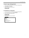
    Quick installation guide 7 connect & login to managed switch 1. Connecting to the ethernet port (rj45 ethernet port) of managed switch. 2. Factory default ip: 10.90.90.90 3. Login with default account and password. Username: admin password: admin cli initialization & configuration 1. Connecting to t...

  • Page 8: Led Status Indications

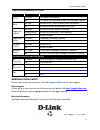
    Quick installation guide 8 led status indications led name indicator /color condition p1/p2 on green p1/p2 power line has power off p1/p2 power line disconnect or does not have power supplied alarm on red ethernet link fails, alarm or power failure alarm occurs off no ethernet link fails and no powe...