Festool CT 33 E Assembly Manual

Other manuals for CT 33 E: Instruction Manual, Instruction Manual

Summary of CT 33 E

  • Page 1

    Air tools assembly manual supplementary guidelines for adapting the ct 33 e dust extractor in order to operate air tools with it. Parts list: • ct 33 e dust extractor (1) • handle (2) • service unit (3) • compressed air module (4) • ias 2 adapter (5) • ias 2 hose (antistatic) 11.5’ (6) • suction hos...

  • Page 2: Fig 3

    Fig 3 step 2: place the lid on a flat surface with internal components facing up (fig 3). Step 3: using a screw driver and a hammer, remove the two round plastic inserts from the lid. Fig 4 step 4: discard the two plastic inserts. Fig 6 fig 5 step 5: place the compressed air module through the two e...

  • Page 3: Fig 8

    Fig 8 step 7: affix the compressed air module on the outside with washer and screw. Fig 9 step 8: tighten both sides with a wrench. Step 9: close the lid. Fig 11 fig 10 step 10: assemble the service unit onto the handle with 2 black screws. Step 11: slide the handle on the back of the vacuum. Fig 12...

  • Page 4: Fig 13

    Fig 13 step 12: place two nuts into the slots on the black part of the handle. Step 13: using two of the silver bolts, screw the handle onto the vacuum. Fig 14 step 14: use two black screws to secure the service unit to the bottom of the vacuum. Fig 15 4.

  • Page 5: Fig 16

    Fig 16 step 15: slide one silver nut into each of the four slots on the vacuum. Step 16: swing the handle brackets to align with the holes. Fig 17 step 17: fasten the gray bracket onto the handle. Fig 18 step 18: secure the bracket to the vacuum with four silver bolts. Fig 19 step 19: slide a nut in...

  • Page 6: Fig 21

    Step 20: use two silver bolts to screw the cord holders onto the handle. Fig 21 step 21: insert the ias-2 adaptor into the hose port. Fig 22 step 22: connect the compressed air module with the ias 2 adaptor. Fig 23 step 23: the air pressure hose that connects the service unit to the compressed air m...

  • Page 7: Fig 27

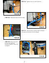
    Step 25: tighten the nut with a wrench. Step 26: clamp the hose to the handle. Fig 27 fig 26 step 27: use the silver-spring hooks to clamp the hose to the front of the vacuum. Fig 28 fig 29 step 28: attach the side of the hose with the vacuum symbol to the ias 2 adaptor. 7.

  • Page 8: Fig 30

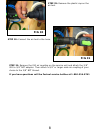
    Fig 30 step 29: remove the plastic cap on the air tool. Fig 31 step 30: connect the air tool to the hose. Step 31: remove the iso air coupling on the service unit and attach the 3/8” iso to 3/8” npt adapter. Then attach a 3/8” or larger male air coupling of your choice to the 3/8” npt thread. If you...