Makita DC24SA Technical Information
Models No.
Description
PRODUCT
T
ECHNICAL INFORMATION
C
ONCEPTION AND MAIN APPLICATIONS
S
pecification
P 1 / 8
DC24SA
Charger
This new charger allows you to charge new Ni-MH battery
from 7.2V to 24V. This charger contains trickle charging function.
Its brief benefits are listed below.
1. The charging time for new 24V Ni-MH batteries is as follows.
* B2417 / 1.7Ah : approx. 30 min.
* B2430 / 3.0Ah ; approx. 60 min.
2. Innovative computer controlled charging system realized most suitable
charge by making the digital communication between charger and battery.
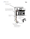
3. Cooling system to keep the ideal temperature for charge.
4. Power display for battery ; It displays the charging amounts of battery
in two steps. (less than 80% or more than 80% of charge)
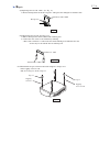
5. The adapter ADP01 (optional acc.) enables to charge the existing
7.2V - 24V Ni-Cd and Ni-MH batteries, too.
6. The adapter ADP02 (optional acc.) enables to refresh inactive
batteries
Continuous Rating (W)
Voltage (V)
Cycle (Hz)
Input
Output
Output Voltage (V)
120
135
135
135
Output
Current (A)
220 - 240
230 - 240
50 - 60
50 - 60
50 - 60
D/C 6.5
D/C 6.5
D/C 6.5
D/C 7.2 - 12
D/C 7.2 - 12
D/C 7.2 - 12
Charging time
New battery
The existing battery
(adaptor is required)
L
W
H
Dimensions : mm ( " )
Width ( W )
Height ( H )
Length ( L )
175 (6-29/32)
110 (4-5/16)
215 (8-15/32)
Voltage ( V )
Charging
time
Ni-MH
Ni-Cd
3.0 Ah
2.6 Ah
2.2 Ah
1.7 Ah
2.0 Ah
1.3 Ah
1.7 Ah
Power display for battery
Cooling fan
Cord length : m (ft)
Net weight :Kg (lbs )
7.2 - 18
7.2 - 18
19.2 - 24
35
35
40
20
60
30
20
17
13
30
1.7 (3.7)
2.0 (6.6)
Yes
Yes
No
No
O
ptional accessories
* Interchangeable adapter ADP01 for the existing batteries
* Refreshing adapter ADP02


