Makita DUC121 Technical Information
P 1/ 8
Model No.
Description
PRODUCT
C
ONCEPT AND MAIN APPLICATIONS
DUC121/ DUC122
14.4V/ 18V Cordless Chain Saw 115mm (4-1/2)
Models DUC121 and DUC122 are cordless chain saws powered by
the following Li-ion battery;
DUC121 (14.4V): BL1415N (1.5Ah), BL1415NA (1.5Ah), BL1430 (3.0Ah),
BL1430A (3.0Ah), BL1440 (4.0Ah) and BL1450 (5.0Ah)
DUC122 (18V): BL1815N (1.5Ah), BL1820 (2.0Ah), BL1830 (3.0Ah),
BL1840 (4.0Ah) and BL1850 (5.0Ah)
These models feature higher operation efficiency and more convenience
than the current 12V Model UC120D.
Note: These products are not compatible with 1.3Ah battery BL1415/ BL1815.
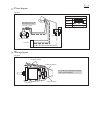
Dimensions: mm (")
Width (W)
Height (H)
Length (L)
422 (16-5/8)
195 (7-5/8)
215 (8-1/2)
T
ECHNICAL INFORMATION
S
pecification
S
tandard equipment
O
ptional accessories
Note: The standard equipment may vary by country or model variation.
*4 Battery, Charger and Plastic carrying case are not supplied with “Z” model
*5 Supplied with the same quantity of extra battery
Battery*
4
Battery cover*
5
Charger*
4
Plastic carrying case*
4
File
Oil supply (containing 100ml of chain oil)
Guide bar cover
Chain blade 25AP-42E
Guide bar
Pruning extension set
Battery
Specification
Weight according to
EPTA-Procedure 01/2003*
1
: kg (lbs)
Capacity: Ah
Cell
Voltage: V
18
Chain speed: m/s (m/min.)
2.6 (5.7)
*
3
14.4
2.5 (5.4)
*
2
1.5, 3.0, 4.0, 5.0
1.5, 2.0, 3.0, 4.0, 5.0
Charging time (approx.): min.
Energy capacity: Wh
27, 36, 54, 72, 90
22, 44, 58, 72
15, 22, 36, 45 with DC18RC
15, 24, 22, 36, 45 with DC18RC
Li-ion
115 (4-1/2)
5.0 (300)
4.8 (290)
*1 With Guide bar, Saw chain
*2 With Battery BL1430, BL1440 or BL1450
*3 With Battery BL1830, BL1840 or BL1850
Cutting length: mm (")
Yes (Electric brake)
Chain brake
Model
DUC121
DUC122
Pitch
Chain blade
Type
1/4"
25AP-42E
L
H
W
Fast charger DC18RC
Charger DC18SD/DC24SC
Automotive charger DC18SE
Four port multi charger DC18SF
Two port multi fast charger DC18RD
For DUC121
Battery BL1415N
Battery BL1415NA
Battery BL1430
Battery BL1430A
Battery BL1440
Battery BL1450
For DUC122
Battery BL1815N
Battery BL1820
Battery BL1830
Battery BL1840
Battery BL1850
OFFICIAL USE
for ASC & Sales Shop


