- DL manuals
- Suzuki
- Automobile
- GRAND VITARA XL-7
- Service Manual
Suzuki GRAND VITARA XL-7 Service Manual
WARNING:
For vehicles equipped with a Supplemental
Restraint (Air Bag) System:
D Service on and around the air bag system
components or wiring must be performed
only by an authorized SUZUKI dealer.
Refer to “Air Bag System Components and
Wiring Location View” under “General De-
scription” in air bag system section in order
to confirm whether you are performing ser-
vice on or near the air bag system compo-
nents or wiring. Please observe all WARN-
INGS and “Service Precautions” under “On-
Vehicle Service” in air bag system section
before performing service on or around the
air bag system components or wiring. Fail-
ure to follow WARNINGS could result in
unintentional activation of the system or
could render the system inoperative. Either
of these two conditions may result in severe
injury.
D If the air bag system and another vehicle
system both need repair, SUZUKI recom-
mends that the air bag system be repaired
first, to help avoid unintended air bag sys-
tem activation.
D Do not modify the steering wheel, instru-
ment panel or any other air bag system com-
ponent (on or around air bag system compo-
nents or wiring). Modifications can adverse-
ly affect air bag system performance and
lead to injury.
D If the vehicle will be exposed to tempera-
tures over 93
_C (200_F) (for example, during
a paint baking process), remove the air bag
system components (air bag (inflator) mod-
ule, sensing and diagnostic module (SDM),
seat belt pretensioner (if equipped) before-
hand to avoid component damage or unin-
tended activation.
IMPORTANT
WARNING/CAUTION /NOTE
Please read this manual and follow its instructions
carefully. To emphasize special information, the
words WARNING, CAUTION and NOTE have spe-
cial meanings. Pay special attention to the messages
highlighted by these signal words.
NOTE:
Indicates special information to make mainte-
nance easier or instructions clearer.
WARNING:
Indicates a potential hazard that could result
in death or injury.
CAUTION:
Indicates a potential hazard that could result
in vehicle damage.
WARNING:
This service manual is intended for authorized
SUZUKI dealers and qualified service me-
chanics only. Inexperienced mechanics or
mechanics without the proper tools and
equipment may not be able to properly per-
form the services described in this manual.
Improper repair may result in injury to the me-
chanic and may render the vehicle unsafe for
the driver and passengers.
Summary of GRAND VITARA XL-7
Page 1
Warning: for vehicles equipped with a supplemental restraint (air bag) system: d service on and around the air bag system components or wiring must be performed only by an authorized suzuki dealer. Refer to “air bag system components and wiring location view” under “general de- scription” in air bag...
Page 2: Foreword
( x ) ( x ) foreword this manual is a supplement to sq416/sq420/sq625 service manual. It has been pre- pared exclusively for the following applicable model. Applicable model: sq420wd (grand vitara rhz diesel engine model) on and after the following vin no. Jsaftd82v00100001 x it described only diffe...
Page 3
0a 0b 1a 3b1 3e 4a2 4b 6 6a3 6b 6c 6e3 6g 6h 6k 7a2 7b1 7c1 7e 7f 8c 8g 1b 6-1 engine engine general information and diagnosis (rhz engine with single-connector ecm) engine general information and diagnosis (rhz engine with triple-connector ecm) engine mechanical (rhz engine) engine cooling engine f...
Page 4: Section 0A
0a general information 0a-1 section 0a general information note: for the descriptions (items) not found in this section, refer to the same section of the service manual men- tioned in foreword of this manual. Contents precautions 0a- 2 . . . . . . . . . . . . . . . . . . . . . . . . . . . . . . . . ...
Page 5: Precautions
0a-2 general information precautions general precautions the warning and caution below describe some general precautions that you should observe when servicing a vehicle. These general precautions apply to many of the service procedures described in this manual, and they will not necessarily be repe...
Page 6
General information 0a-3 “a” d when removing the battery, be sure to disconnect the nega- tive cable first and then the positive cable. When reconnect- ing the battery, connect the positive cable first and then the negative cable, and replace the terminal cover. D when removing parts that are to be ...
Page 7
0a-4 general information d when disconnecting vacuum hoses, attach a tag describing the correct installation positions so that the hoses can be re- installed correctly. D after servicing fuel, oil, coolant, vacuum, exhaust or brake systems, check all lines related to the system for leaks. D for vehi...
Page 8: Identification Information
4-speed a / t m / t general information 0a-5 identification information vehicle identification number the number is punched on the chassis inside the tire housing on the right front side. Engine identification number the number is punched on the cylinder block. Transmission identification number the...
Page 9
Note: air bag caution / warning labels are attached on the vehicle equipped with air bag system only. 1. Air bag label 2. Smoke level label 3. Air bag label on sun visor 4. Radiator cooling fan label 5. Degassing tank cap (radiator cap) label 6. Transfer label 7. Air bag label on wire harness 8. Air...
Page 10: Fastener Information
1. Diameter 2. Pitch general information 0a-7 fastener information metric fasteners most of the fasteners used for this vehicle are metric fasteners. When replacing any fasteners, it is most important that replacement fasteners be the correct diameter, thread pitch and strength. Caution: note that b...
Page 11: Section 0B
0b maintenance and lubrication 0b-1 section 0b maintenance and lubrication warning: for vehicles equipped with supplemental restraint (air bag) system: d service on and around the air bag system components or wiring must be performed only by an autho- rized suzuki dealer. Refer to “air bag system co...
Page 12: Maintenance Schedule
0b-2 maintenance and lubrication maintenance schedule maintenance schedule under normal driving conditions interval: this interval should be judged by this table includes services as scheduled up to 90,000 km (54,000 miles) mileage. Beyond 90,000 km (54,000 miles), carry out the same services at the...
Page 13
Maintenance and lubrication 0b-3 interval: this interval should be judged by this table includes services as scheduled up to 90,000 km (54,000 miles) mileage. Beyond 90,000 km (54,000 miles), carry out the same services at the same intervals respectively. This interval should be judged by odometer r...
Page 14
0b-4 maintenance and lubrication maintenance recommended under severe driving conditions if the vehicle is usually used under the conditions corresponding to any severe condition code given below, it is rec- ommended that applicable maintenance operation be performed at the particular interval as gi...
Page 15: Maintenance Service
3. Zero wear mark maintenance and lubrication 0b-5 maintenance service engine item 1-1 accessory drive belt inspection and replacement warning: all inspection and replacement are to be performed with engine not running. Inspection 1) disconnect negative cable at battery. 2) inspect belt for cracks, ...
Page 16
1. Oil filter 0b-6 maintenance and lubrication item 1-2 camshaft timing belt replacement replace belt with new one. Refer to “timing belt” in section 6a3 for replacement procedure. Caution: d do not bend or twist timing belt. D do not allow timing belt to come into contact with oil, wa- ter, etc. It...
Page 17
1. Oil filter 1. Low level mark 2. Full level mark maintenance and lubrication 0b-7 4) apply engine oil to new oil filter o-ring. 5) screw new filter on oil filter stand by hand. 6) tighten filter to specified torque. Special tool (a): 09915-46510 tightening torque (a): 14 n . M (1.4 kg-m, 10.5 lb-f...
Page 18
0b-8 maintenance and lubrication item 1-4 engine coolant change warning: to help avoid danger of being burned, do not remove degas- sing tank cap while engine and radiator are still hot. Scald- ing fluid and steam can be blown out under pressure if cap is taken off too soon. Caution: when changing e...
Page 19
1. Heater (glow) plug maintenance and lubrication 0b-9 item 1-5 exhaust system inspection warning: to avoid danger of being burned, do not touch exhaust sys- tem when it is still hot. Any service on exhaust system should be performed when it is cool. Check exhaust system as follows: d check rubber m...
Page 20
0b-10 maintenance and lubrication air cleaner filter inspection 1) visually check that air cleaner filter is not excessively dirty, dam- aged or oily. 2) clean filter with compressed air from air outlet side of filter (i.E., the side facing up when installed). Item 3-2 fuel lines and connections ins...
Page 21
1. Drain plug 2. Filler / level plug 1-1. Level gauge with hot level mark 1-2. Level gauge with hot and cold level marks - 2. Full hot mark - 3. Low hot mark - 4. Full cold mark - 5. Low cold mark 1. Drain plug 1 maintenance and lubrication 0b-11 chassis and body item 6-10 manual transmission oil in...
Page 22
0b-12 maintenance and lubrication the figure shows right-hand steering vehicle fluid cooler hose change replace inlet and outlet hoses of cooler hose and their clamps. For replacement procedure, refer to on-vehicle service in section 7b1. Item 6-15 power steering (p / s) system inspection (if equipp...
Page 23
Maintenance and lubrication 0b-13 recommended fluids and lubricants engine oil minimum quality level required is ; 5w-30 : api cf (except cf-2) or acea b3-98 15w-40 : api sg / cf (except cf-2) or acea b2-96 (refer to engine oil viscosity chart in item 1-3) engine coolant ethylene-glycol base coolant...
Page 24: Section 1A
Heater and ventilation 1a-1 1a section 1a heater and ventilation warning: for vehicles equipped with supplement restraint (air bag) system d service on and around the air bag system components or wiring must be performed only by an autho- rized suzuki dealer. Refer to “air bag system components and ...
Page 25: General Description
1. Air inlet box 2. Cooling unit 3. Heater unit 4. Heater core 5. Supplementary heater 6. A / c evaporator and expansion valve 7. Fresh air 8. Recirculation air 9. Ventilation air 10. Demister air 11. Foot air 12. Defroster air 1a-2 heater and ventilation general description supplementary heater the...
Page 26
1. Main fuse box 2. Generator 3. Ignition switch 4. Circuit fuse box 5. Cassette fuse 6. Cassette fuse 7. Radiator fan motor no.1 8. Radiator fan relay 1 (high) 9. Radiator fan relay 2 (high) 10. Radiator fan relay 3 (low) 11. Radiator fan motor no.2 12. Blower fan relay 13. Blower motor 14. Blower ...
Page 27: On-Vehicle Service
1a-4 heater and ventilation on-vehicle service supplementary heater removal 1) remove heater unit referring to heater unit removal in this section. 2) detach clamp to separate heater unit upper and lower cases from each other. 3) remove upper case and remove supplementary heater (1) from lower case ...
Page 28
Heater and ventilation 1a-5 radiator fan signal relay inspection 1) disconnect negative (–) cable at battery. 2) remove supplementary ceramic heater relay (1) from junction box (2). 3) check that there is continuity between terminal “c” and “d”. If there is no continuity, replace relay. 4) check tha...
Page 29
2. Indicator lamp 3. Illumination lamp 1a-6 heater and ventilation inspection d check for switch and lamps by tester. If there is continuity between terminal as shown in table, supple- mentary heater switch (1) functions good. Installation reverse removal procedure for installation..
Page 30: Section 1B
1b air conditioning (optional) 1b-1 general description 1b- 2 . . . . . . . . . . . . . . Major components and location 1b- 2 . . . . . . . Diagnosis 1b- 3 . . . . . . . . . . . . . . . . . . . . . . . . . . . General 1b- 3 . . . . . . . . . . . . . . . . . . . . . . . . . . . . . Wiring circuit 1b-...
Page 31: General Description
1. Cooling unit 2. Compressor 3. Condenser assembly 4. Receiver / dryer 5. Discharge hose 6. Suction hose 7. Condenser outlet pipe 8. Liquid pipe 9. Expansion valve 10. Ventilation air 11. Foot air 12. Defroster air 13. Demister air 14. Fresh air 15. Recirculation air 16. Heater unit 17. Air inlet b...
Page 32: Diagnosis
Air conditioning (optional) 1b-3 diagnosis general condition possible cause correction cool air won’t come out (a / c system won’t operative) d no refrigerant d fuse blown d a/c switch faulty d blower motor switch faulty d a/c evaporator thermistor faulty d dual pressure switch faulty d wiring or gr...
Page 33
1b-4 air conditioning (optional) condition possible cause correction cool air does not come out or insufficient cooling (a / c system normal operative) d compressor faulty d air in a/c system d air leaking from cooling unit or air duct d heater and ventilation system faulty d blower motor faulty d e...
Page 34
For lh model 1. Main fuse box 2. Generator 3. Ignition switch 4. Circuit fuse box 5. Cassette fuse (compressor and condenser fan motor fuse) 6. Cassette fuse (radiator fan motor and battery fuses) 7. Radiator fan motor no.1 8. Radiator fan relay 1 (high) 9. Radiator fan relay 2 (high) 10. Radiator f...
Page 35
1. Main fuse box 2. Generator 3. Ignition switch 4. Circuit fuse box 5. Cassette fuse (compressor and condenser fan motor fuse) 6. Cassette fuse (radiator fan motor and battery fuses) 7. Radiator fan motor no.1 8. Radiator fan relay 1 (high) 9. Radiator fan relay 2 (high) 10. Radiator fan relay 3 (l...
Page 36
Air conditioning (optional) 1b-7 fig. A fig. B ac1-15 inspection of a/c controller and its circuits caution: a / c controller and ecm cannot be checked by itself. It is strictly prohibited to connect voltmeter or ohmmeter to a / c controller and ecm with couplers disconnected from it. A / c system c...
Page 37
System circuit terminal arrangement of a / c controller (viewed from harness side) terminal arrangement of ecm (viewed from harness side) a. To double relay b. To “front blow” fuse c. To “ig meter” fuse d. To “25a a / c” fuse e. To “40a” cassette fuse f. To “rear defg” fuse 1. Blower motor relay 2. ...
Page 38
Air conditioning (optional) 1b-9 a/ c controller voltage values table termi- nal wire color circuit measurement ground normal value condition ac1-1 p compressor magnet clutch relay drive ground to engine (fig. B) – 0.3 – 0.3 v fulfill all the following conditions dblower fan motor switch on dfulfill...
Page 39
1b-10 air conditioning (optional) ecm voltage values table termi- nal wire circuit measurement ground normal value condition c51 8 radiator fan ecm ground –0.3 – 0.3 v radiator fan state off with engine running c51-8 e227-4 bl / b radiator fan motor state ecm ground terminal 4 – 5 v radiator fan sta...
Page 40
Air conditioning (optional) 1b-11 compressor drive belt inspection d check compressor drive belt (1) for wear and cracks, and replace as necessary. D check compressor drive belt (1) tension by measuring how much it deflects when pushed at intermediate point between compres- sor pulley (2) and crank ...
Page 41: On-Vehicle Service
1b-12 air conditioning (optional) 3. “25 a a / c” fuse 4 5 on-vehicle service relays note: refer to “radiator fan control system” in section 6e3 for radiator fan relay 1, radiator fan relay 2 and radiator fan relay 3. Inspection 1) disconnect negative (–) cable at battery. 2) remove condenser coolin...
Page 42
Air conditioning (optional) 1b-13 compressor assembly removal 1) run engine at idle with a / c on for 10 minutes. 2) disconnect negative (–) cable at battery. 3) remove air cleaner outlet hose (1). 4) recover refrigerant from refrigeration system using recovery and recycling equipment. Note: the amo...
Page 43: Required Service Material
1b-14 air conditioning (optional) installation 1) pour new compressor oil. The amount must be the same with the amount measured in “removal”. Note: compressor supplied from factory is filled up with the fol- lowing amount of oil. Amount of oil in compressor: 120 cm 3 (120 cc) 2) install compressor (...
Page 44: Section 3B1
3b1 power steering (p / s) system 3b1-1 section 3b1 power steering (p/s) system warning: for vehicles equipped with supplemental restraint (air bag) system: d service on and around the air bag system components or wiring must be performed only by an autho- rized suzuki dealer. Refer to “air bag syst...
Page 45: General Description
1 3 2 1. P / s fluid reservoir 2. Gear box 3. P / s pump 3b1-2 power steering (p / s) system general description power steering (p/s) pump assembly power steering (p / s) pump specification: the specification of this p / s pump assembly is the same as the specification of the same section in the ser...
Page 46
Power steering (p / s) system 3b1-3 1. P / s fluid reservoir 2. Gauge valve (open) 3. P / s pump 4. P / s gear box 5. High pressure side 6. Low pressure side 1. P / s fluid reservoir 2. Gauge valve (open) 3. P / s pump 4. P / s gear box 5. High pressure side 6. Low pressure side 50 °c {122 °f} hydra...
Page 47
1. P / s fluid reservoir 2. Gauge valve (shut) 3. Oil pressure gauge 4. P / s pump 5. P / s gear box 1. P / s fluid reservoir 3. Gauge valve (open) 3. Oil pressure gauge 4. P / s pump 5. P / s gear box 3b1-4 power steering (p / s) system 5) check relief pressure a) increase engine speed to about 1,5...
Page 48: On-Vehicle Service
[lh] [rh] tightening torque (a): 60 n . M (6.0 kg-m, 43.5 lb-ft) (b): 35 n . M (3.5 kg-m, 25.5 lb-ft) (c): 25 n . M (2.5 kg-m, 18.5 lb-ft) 1. Power steering pump assembly 2. P / s fluid reservoir 3. High pressure hose & pipe 4. Suction pipe 5. Low pressure return pipe 6. Steering gear case [lh] : fo...
Page 49
3b1-6 power steering (p / s) system 1. P/s fluid reservoir f: forward 1. P / s pulley 2. Mounting bolt f removal note: be sure to clean each joint of suction and discharge sides thoroughly before removal. 1) remove suction hose from pump, then disconnect battery nega- tive cable. 2) remove p / s flu...
Page 50: Required Service Materials
Power steering (p / s) system 3b1-7 09915-77420 oil pressure gauge attachment and hose set 09915-77410 oil pressure gauge tightening torque specifications fastening parts tightening torque fastening arts n . M kg-m lb-ft gear box mounting bolts 55 5.5 40.0 gear box cylinder pipe flare nuts 29 2.9 21...
Page 51: Section 3E
3e rear suspension 3e-1 on-vehicle service 3e-1 . . . . . . . . . . . . . . . . Rear axle shaft and wheel bearing 3e-1 . . . . . . . . . . . . . . . . . . . . . . . . . . Rear axle housing 3e-2 . . . . . . . . . . . . . . . Tightening torque specification 3e-3 . Required service material 3e-3 . . . ...
Page 52
1 (a), “a” 3e-2 rear suspension rear axle housing installation for the details, refer to the same item of the same section in the ser- vice manual mentioned in the foreword of this manual noting following points. D clean mating surfaces of axle housing (1) and differential carrier and apply sealant ...
Page 53: Required Service Material
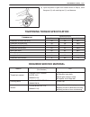
Rear suspension 3e-3 tightening torque specification fastening part tightening torque fastening part n . M kg-m lb-ft shock absorber nut 29 2.9 21.0 shock absorber lower nut 85 8.5 61.5 lower rod bolt and nut 90 9.0 65.0 upper rod bolt and nut 90 9.0 65.0 lateral rod bolt 90 9.0 65.0 differential ca...
Page 54: Special Tool
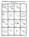
09942-15510 sliding hammer 09943-35512 brake drum remover 09944-88210 bearing installer 3e-4 rear suspension special tool.
Page 55: Section 4A2
4a2 front drive shaft / shaft bearing, oil seal 4a2-1 section 4a2 front drive shaft/shaft bearing, oil seal note: for the descriptions (items) not found in this section, refer to the same section of the service manual men- tioned in the foreword of this manual. Contents on-vehicle service 4a2-2 . . ...
Page 56: On-Vehicle Service
Wheel side 4a2-2 front drive shaft / shaft bearing, oil seal on-vehicle service drive shaft assembly caution: d to prevent any problem caused by washing solution, do not wash joint boots. Degreasing of those parts with cloth is allowed. D bend each boot band against forward rotation. D do not squeez...
Page 57
[lh] [rh] differential side front drive shaft / shaft bearing, oil seal 4a2-3 6) install circlip (1) by using snap ring plier. 7) apply grease to entire surface of cage. Use joint grease in tube included in spare part. 8) insert cage into outer race and fit circlip (1) into groove of outer race. Cau...
Page 58: Required Service Material
4a2-4 front drive shaft / shaft bearing, oil seal required service material material recommended suzuki product use lithium grease suzuki super grease a (99000-25010) drive shaft oil seal wheel spindle part of differential side drive shaft (rh) sealant sealing compound 366e (99000-31090) axle shaft ...
Page 59: Section 4B
4b propeller shafts 4b-1 section 4b propeller shafts note: for the descriptions (items) not found in this section, refer to the same section of the service manual men- tioned in the foreword of this manual. Contents on-vehicle service 4b-2 . . . . . . . . . . . . . . . . . . . . . . . . . . . . . . ...
Page 60: On-Vehicle Service
4b-2 propeller shafts on-vehicle service propeller shaft installation reverse removal procedure to install propeller shaft. D use following specification to torque universal joint flange bolts and nuts. Tightening torque front propeller shaft flange nuts: 50 n . M (5.0 kg-m, 36.5 lb-ft) rear propell...
Page 61: Section 6
6 engine general information and diagnosis (rhz engine with single-connector ecm) 6-1 general information 6- 3 . . . . . . . . . . . . . . Engine diagnosis 6- 6 . . . . . . . . . . . . . . . . . . . General description 6- 6 . . . . . . . . . . . . . . . . . . . . On-board diagnostic system 6- 6 . . ...
Page 62
6-2 engine general information and diagnosis (rhz engine with single-connector ecm) dtc p1112 (p0230) fuel pressure monitoring circuit malfunction 6- 42 . . . . . . . . . Dtc p0201 (p0200) injector circuit malfunction cylinder 1 6- 44 . . . . . . . . . . . . . . . Dtc p0202 (p0200) injector circuit ...
Page 63: General Information
1. No.1 cylinder 2. No.2 cylinder 3. No.3 cylinder 4. No.4 cylinder engine general information (rhz engine with single-connector ecm) 6-3 general information statement of cleanliness and care an automobile engine is a combination of many machined, honed, polished and lapped surfaces with tolerances ...
Page 64
6-4 engine general information (rhz engine with single-connector ecm) precaution on fuel system service d work must be done with no smoking, in a well-ventilated area and away from any open flames. D a small amount of fuel may be released after fuel line is discon- nected. In order to reduce the cha...
Page 65
Engine general information (rhz engine with single-connector ecm) 6-5 fuel pressure relief procedure refer to “fuel delivery system precaution” in section 6e3. Fuel leakage check procedure after performing any service on fuel system, check to make sure that there are no fuel leakages as follows. 1) ...
Page 66: Engine Diagnosis
1 1. Malfunction indicator lamp (mil) 2. Data link connector (dlc) 3. Suzuki scan tool (tech 1) 2 3 or 6-6 engine diagnosis (rhz engine with single-connector ecm) engine diagnosis general description this vehicle is equipped with an engine and emission control system which are under control of ecm (...
Page 67
Engine diagnosis (rhz engine with single-connector ecm) 6-7 warm-up cycle a “warm-up cycle” means sufficient vehicle operation such that the coolant temperature has risen by at least 22 _c (40_f) from engine starting and reaches a minimum temperature of 70 _c (160_f). Driving cycle a “driving cycle”...
Page 68
Body ground ecm (pcm) ground k line of iso 9141 suzuki serial data line l line of iso 9141 6-8 engine diagnosis (rhz engine with single-connector ecm) freeze frame data clearance: the freeze frame data is cleared at the same time as clearance of diagnostic trouble code (dtc). Data link connector (dl...
Page 69
Engine diagnosis (rhz engine with single-connector ecm) 6-9 precaution in diagnosing trouble d don’t disconnect couplers from ecm (pcm), battery cable from battery, ecm (pcm) ground wire harness from engine or main fuse before confirming diagnostic information (dtc, freeze frame data, etc.) stored i...
Page 70
6-10 engine diagnosis (rhz engine with single-connector ecm) engine diagnostic flow table refer to the following pages for the details of each step. Step action yes no 1 customer complaint analysis 1) perform customer complaint analysis. Was customer complaint analysis performed? Go to step 2. Perfo...
Page 71
Engine diagnosis (rhz engine with single-connector ecm) 6-11 1. Customer complaint analysis record details of the problem (failure, complaint) and how it occurred as described by the customer. For this purpose, use of such an inspection form will facilitate collecting information to the point requir...
Page 72
6-12 engine diagnosis (rhz engine with single-connector ecm) customer problem inspection form (example) user name: model: vin: date of issue: date reg. Date of problem: mileage: problem symptoms vdifficult starting vpoor driveability vno cranking vno initial combustion vpoor starting at (vcold/vwarm...
Page 73
Or engine diagnosis (rhz engine with single-connector ecm) 6-13 malfunction indicator lamp (mil) check 1) turn on ignition switch (but the engine at stop) and check that mil lights. If mil does not light up or dims, go to “diagnostic flow table a-1” for troubleshooting. 2) start engine and check tha...
Page 74
6-14 engine diagnosis (rhz engine with single-connector ecm) fail-safe table when any of the following dtcs is detected, ecm (pcm) enters fail-safe mode as long as malfunction continues to exist but that mode is canceled when ecm detects normal condition after that. Dtc no. Trouble area fail safe op...
Page 75
Engine diagnosis (rhz engine with single-connector ecm) 6-15 diagnostic trouble code (dtc) table dtc no. Detecting item detecting condition (dtc will set when detecting:) dtc driving cycle mil p0100 (p0100) mass air flow sensor circuit malfunction sensor output low or high voltage 1 driving cycle 1 ...
Page 76
6-16 engine diagnosis (rhz engine with single-connector ecm) dtc no. Detecting item detecting condition (dtc will set when detecting:) dtc driving cycle mil l p0335 (p0335) crankshaft position sensor circuit mal- function monitor signal of crankshaft position sensor is lower or higher than specifica...
Page 77
Engine diagnosis (rhz engine with single-connector ecm) 6-17 dtc no. Detecting item detecting condition (dtc will set when detecting:) dtc driving cycle mil p1110 a / c cut signal circuit malfunction monitor signal of a / c cut signal circuit is different from command signal (circuit open or short) ...
Page 78
6-18 engine diagnosis (rhz engine with single-connector ecm) operation visual inspection visually check following parts and systems. Inspection item referring section d engine oil – – – – – level, leakage d engine coolant – – – – – level, leakage d fuel – – – – – level, leakage d a/t fluid – – – – –...
Page 79
Engine diagnosis (rhz engine with single-connector ecm) 6-19 engine basic check this check is very important for troubleshooting when ecm (pcm) has detected no dtc and no abnormality has been found in visual inspection. Follow the flow table carefully. Step action yes no 1 was “engine diag. Flow tab...
Page 80
6-20 engine diagnosis (rhz engine with single-connector ecm) engine diagnosis table perform troubleshooting referring to following table when ecm (pcm) has detected no dtc and no abnormality has been found in visual inspection and engine basic inspection previously. Condition possible cause referenc...
Page 81
Engine diagnosis (rhz engine with single-connector ecm) 6-21 condition possible cause reference item improper engine idling or engine fails to idle intake system out of order. D clogged air cleaner element d egr throttle valve fuel system out of order. D shortage of fuel in fuel tank d fuel filter –...
Page 82
6-22 engine diagnosis (rhz engine with single-connector ecm) condition possible cause reference item abnormal knocking fuel system out of order. D fuel injection pipe – cracks – fuel leakage from joints d faulty fuel injector – incorrect valve opening pressure – seized needle valve – improperly inst...
Page 83
Engine diagnosis (rhz engine with single-connector ecm) 6-23 condition possible cause reference item overheating d insufficient coolant d loose water pump belt d inoperative thermostat d poor water pump performance d clogged or leaky radiator d improper engine oil grade d clogged oil filter or oil s...
Page 84
6-24 engine diagnosis (rhz engine with single-connector ecm) condition possible cause reference item engine noise note: before check- ing the mechanical noise, make sure that: d injection timing is properly adjusted. D specified fuel is used. Valve noise. D improper valve lash d worn valve stem and ...
Page 85
6. Lock lever 3. Ecm cover engine diagnosis (rhz engine with single-connector ecm) 6-25 inspection of pcm (ecm) and its circuits pcm (ecm) and its circuits can be checked at pcm (ecm) wiring couplers by measuring voltage and resistance. Caution: pcm / ecm cannot be checked by itself. It is strictly ...
Page 86
1. Pcm (ecm) 2. Pcm (ecm) connector (viewed from harness side) 1.2 mm 4.6 mm 6-26 engine diagnosis (rhz engine with single-connector ecm) 6) install ecm cover (1) to ecm connector and tighten screw (5). 7) install harness cover (2) to ecm connector assembly (3) by fas- tening clamp (4) and then lock...
Page 87
1. Ecm / pcm coupler disconnected 2. Ohmmeter engine diagnosis (rhz engine with single-connector ecm) 6-27 resistance check 1) disconnect couplers from ecm / pcm with ignition switch off. Caution: never touch terminals of ecm / pcm itself or connect voltmeter or ohmmeter. 2) check resistance between...
Page 88
6-28 engine diagnosis (rhz engine with single-connector ecm) 1. Ecm (pcm) 2. To ignition switch 3. Main fuse 4. Double relay 5. To radiator fan relay no.3 table a-1 malfunction indicator lamp circuit check – mil does not come “on” or dims at ignition switch on (but engine at stop) wiring diagram cir...
Page 89
Engine diagnosis (rhz engine with single-connector ecm) 6-29 table a-2 malfunction indicator lamp circuit check – mil remains “on” after engine starts wiring diagram / circuit description refer to table a-1. Inspection step action yes no 1 dtc check. 1) with ignition switch off, install scan tool. 2...
Page 90
6-30 engine diagnosis (rhz engine with single-connector ecm) table a-3 inspection step action yes no 1 double relay operating sound check: is operating sound of double relay heard at ignition switch on? Go to step 5. Go to step 2. 2 fuse check: is main “fi” fuse in good condition? Go to step 3. Chec...
Page 91
1. Mass air flow sensor 2. Ecm 3. Ignition switch 4. “ig” fuse (20 a) 5. Main fuse 4 3 5 engine diagnosis (rhz engine with single-connector ecm) 6-31 dtc p0100 (dtc p0100) mass air flow circuit malfunction wiring diagram dtc confirmation procedure note: check to make sure that the following conditio...
Page 92
6-32 engine diagnosis (rhz engine with single-connector ecm) troubleshooting step action yes no 1 was “engine diag. Flow table” performed? Go to step 2. Go to “engine diag. Flow table”. 2 maf sensor power supply check: 1) with ignition switch off, disconnect maf sensor coupler. 2) with ignition swit...
Page 93
Engine diagnosis (rhz engine with single-connector ecm) 6-33 dtc p0101 (p0100) maf sensor circuit range/performance problem wiring diagram refer to dtc p0100. Dtc confirmation procedure note: check to make sure that the following conditions are satisfied when using this dtc confirmation pro- cedure....
Page 94
6-34 engine diagnosis (rhz engine with single-connector ecm) 1. Mass air flow sensor 2. Ecm dtc p0110 intake air temp. (iat) circuit malfunction wiring diagram dtc confirmation procedure 1) connect scan tool to dlc with ignition switch off. 2) turn on ignition switch and clear dtc, pending dtc and f...
Page 95
Engine diagnosis (rhz engine with single-connector ecm) 6-35 troubleshooting step action yes no 1 was “engine diag. Flow table” performed? Go to step 2. Go to “engine diag. Flow table”. 2 check iat sensor and its circuit. 1) connect scan tool with ignition switch off. 2) turn ignition switch on. 3) ...
Page 96
6-36 engine diagnosis (rhz engine with single-connector ecm) 1. Engine coolant temperature sensor 2. Ecm dtc p0115 (dtc p0115) engine coolant temp. Sensor circuit malfunction wiring diagram dtc confirmation procedure 1) connect scan tool to dlc with ignition switch off. 2) turn on ignition switch an...
Page 97
Engine diagnosis (rhz engine with single-connector ecm) 6-37 1. Throttle position sensor 2. Ecm 3. Brake lamp switch 4. “stop” fuse (20 a) dtc p0121 (dtc p0120) throttle position circuit range/performance problem dtc p0604 (p0120) throttle position sensor monitoring system malfunction wiring diagram...
Page 98
6-38 engine diagnosis (rhz engine with single-connector ecm) troubleshooting step action yes no 1 was “engine diag. Flow table” performed? Go to step 2. Go to “engine diag. Flow table”. 2 check sensor power supply circuit is dtc below also indicated? P1614 scan tool> p0560 go to dtc p1614 (p0560) di...
Page 99
Engine diagnosis (rhz engine with single-connector ecm) 6-39 1. Fuel temperature sensor 2. Ecm dtc p0180 fuel temp. Sensor circuit malfunction wiring diagram dtc confirmation procedure 1) connect scan tool to dlc with ignition switch off. 2) turn on ignition switch and clear dtc, pending dtc and fre...
Page 100
6-40 engine diagnosis (rhz engine with single-connector ecm) 1. Fuel pressure sensor 2. Ecm dtc p0190 (p0190) fuel rail pressure sensor circuit malfunction wiring diagram dtc confirmation procedure 1) connect scan tool to dlc with ignition switch off. 2) turn on ignition switch and clear dtc, pendin...
Page 101
Engine diagnosis (rhz engine with single-connector ecm) 6-41 troubleshooting step action yes no 1 was “engine diag. Flow table” performed? Go to step 2. Go to “engine diag. Flow table”. 2 check sensor power supply circuit 1) connect scan tool to dlc with ignition switch off and then turn ignition sw...
Page 102
6-42 engine diagnosis (rhz engine with single-connector ecm) 1. Double relay 2. Fuel pressure regulator 3. Fuel pressure sensor 4. Ecm 5. Double relay fuse (30 a) 5 5 dtc p0191 (p0230) fuel rail pressure sensor/pressure regulator consistency function dtc p1112 (p0230) fuel pressure monitoring circui...
Page 103
Engine diagnosis (rhz engine with single-connector ecm) 6-43 troubleshooting step action yes no 1 was “engine diag. Flow table” performed? Go to step 2. Go to “engine diag. Flow table”. 2 check fuel shortage 1) is there enough fuel in fuel tank? Go to step 3. Supply fuel into fuel tank. 3 check wire...
Page 104
6-44 engine diagnosis (rhz engine with single-connector ecm) 1. Fuel injector no.1 2. Fuel injector no.2 3. Fuel injector no.3 4. Fuel injector no.4 5. Ecm dtc p0201 (p0200) injector circuit malfunction cylinder 1 dtc p0202 (p0200) injector circuit malfunction cylinder 2 dtc p0203 (p0200) injector c...
Page 105
Engine diagnosis (rhz engine with single-connector ecm) 6-45 troubleshooting step action yes no 1 was “engine diag. Flow table” performed? Go to step 2. Go to “engine diag. Flow table”. 2 check fuel injector circuit for short 1) with ignition switch off, disconnect ecm connector. 2) check for proper...
Page 106
6-46 engine diagnosis (rhz engine with single-connector ecm) 1. Double relay 2. Ecm 3. Double relay fuse (30 a) 4. To radiator fan relay no.3 dtc p0215 double relay circuit malfunction wiring diagram dtc confirmation procedure 1) connect scan tool to dlc with ignition switch off. 2) turn on ignition...
Page 107
Engine diagnosis (rhz engine with single-connector ecm) 6-47 1. Double relay 2. Ecm 3. Fuel pump 4. “fuel pump” fuse (15 a) 5. Double relay fuse (30 a) 6. To radiator fan relay no.3 dtc p0230 fuel pump supply circuit malfunction wiring diagram dtc confirmation procedure 1) connect scan tool to dlc w...
Page 108
1. Double relay 2. Ecm 3. Boost pressure regulator solenoid valve 4. Fuel pump 5. “eng” fuse (15 a) 6. “fuel pump” fuse (15 a) 6-48 engine diagnosis (rhz engine with single-connector ecm) dtc p0243 (p0243) turbo pressure solenoid valve circuit range/ performance problem wiring diagram dtc confirmati...
Page 109
Engine diagnosis (rhz engine with single-connector ecm) 6-49 troubleshooting step action yes no 1 was “engine diag. Flow table” performed? Go to step 2. Go to “engine diag. Flow table”. 2 is operating sound heard from fuel pump? Go to step 3. Proceed to dtc p0230 diag. Flow table. 3 check wire harne...
Page 110
6-50 engine diagnosis (rhz engine with single-connector ecm) dtc p0245 (p0243)/p0246 (p0243) turbo pressure solenoid valve circuit range/performance problem wiring diagram refer to dtc p0243 (p0243). Troubleshooting step action yes no 1 was “engine diag. Flow table” performed? Go to step 2. Go to “e...
Page 111
1. Pre post heating relay (control unit) 2. Ecm 3. Glow plugs 4. Main fuse 5. From ignition switch engine diagnosis (rhz engine with single-connector ecm) 6-51 dtc p0380 (p0380)/p1404 (p0380) pre/post heat relay circuit malfunction wiring diagram dtc confirmation procedure 1) connect scan tool to dl...
Page 112
1. Glow indicator lamp 2. Ecm 6-52 engine diagnosis (rhz engine with single-connector ecm) dtc p0381 glow indicator lamp circuit malfunction wiring diagram dtc confirmation procedure 1) connect scan tool to dlc with ignition switch off. 2) turn on ignition switch and clear dtc, pending dtc and freez...
Page 113
Engine diagnosis (rhz engine with single-connector ecm) 6-53 dtc p0401 (p0903) egr solenoid valve flow insufficient detected dtc p0402 (p0903) egr solenoid valve flow excessive detected dtc confirmation procedure 1) connect scan tool to dlc with ignition switch off. 2) turn on ignition switch and cl...
Page 114
1. Double relay 2. Ecm 3. Egr solenoid valve 4. Booster pump 5. “eng” fuse (15 a) 6. “fuel pump” fuse (15 a) 6-54 engine diagnosis (rhz engine with single-connector ecm) dtc p0403 (p0403) egr solenoid valve circuit malfunction wiring diagram dtc confirmation procedure 1) connect scan tool to dlc wit...
Page 115
1. Double relay 2. Ecm 3. Ignition switch 4. “ig” fuse 5. Main fuse 6. To radiator fan relay no.3 engine diagnosis (rhz engine with single-connector ecm) 6-55 dtc p0561 (p0560) stabilization of sensor supply dtc p0603/p0606/p1171/p1617 ecm function dtc p1169 (p0170) condenser voltage function 1 dtc ...
Page 116
1. Radiator fan motor 1 2. Radiator fan relay 1 (high / low) 3. Radiator fan relay 2 (high) 4. Radiator fan relay 3 (low) 5. Radiator fan motor 2 6. Ecm 7. “rear defg” fuse (25 a) 8. From battery 9. Double relay 6-56 engine diagnosis (rhz engine with single-connector ecm) dtc p1108 radiator fan high...
Page 117
Engine diagnosis (rhz engine with single-connector ecm) 6-57 dtc p1109 radiator fan low speed circuit malfunction wiring diagram refer to dtc p1108. Dtc confirmation procedure 1) connect scan tool to dlc with ignition switch off. 2) turn on ignition switch and clear dtc, pending dtc and freeze flame...
Page 118
1. A / c control module 2. Ecm 6-58 engine diagnosis (rhz engine with single-connector ecm) dtc p1110 a/c signal circuit malfunction wiring diagram dtc confirmation procedure 1) connect scan tool to dlc with ignition switch off. 2) turn on ignition switch and clear dtc, pending dtc and freeze flame ...
Page 119
1. Double relay 2. Ecm 3. Injection pump solenoid valve (3rd piston deactivator) 4. Fuel pump 5. “eng” fuse (15 a) 6. “fuel pump” fuse (15 a) c51-80 red / grn engine diagnosis (rhz engine with single-connector ecm) 6-59 dtc p1135 3rd piston deactivator (injection pump solenoid valve) circuit malfunc...
Page 120
6-60 engine diagnosis (rhz engine with single-connector ecm) 1. Double relay 2. Ecm 3. Fuel pressure regulator dtc p1138 (p0230) fuel pressure regulator circuit malfunction wiring diagram dtc confirmation procedure 1) connect scan tool to dlc with ignition switch off. 2) turn on ignition switch and ...
Page 121
1. Double relay 2. Ecm 3. Egr throttle solenoid valve 4. Fuel pump 5. “eng” fuse (15 a) 6. “fuel pump” fuse (15 a) engine diagnosis (rhz engine with single-connector ecm) 6-61 dtc p1402 (p0510) throttle solenoid valve circuit malfunction wiring diagram dtc confirmation procedure 1) connect scan tool...
Page 122
1. Ignition switch 2. Ecm 3. “ig meter” fuse (20 a) 4. Main fuse 6-62 engine diagnosis (rhz engine with single-connector ecm) dtc p1511 ignition switch circuit malfunction wiring diagram dtc confirmation procedure 1) connect scan tool to dlc with ignition switch off. 2) turn on ignition switch and c...
Page 123
Engine diagnosis (rhz engine with single-connector ecm) 6-63 dtc p1519 radiator fan circuit malfunction wiring diagram refer to dtc p1108 / p1109. Troubleshooting proceed to dtc p1108 and p1109 troubleshooting..
Page 124
1. Malfunction indicator lamp (mil) 2. Ecm 3. Ignition switch 4. “ig” fuse (20 a) 6-64 engine diagnosis (rhz engine with single-connector ecm) dtc p1606 mil circuit malfunction wiring diagram dtc confirmation procedure 1) connect scan tool to dlc with ignition switch off. 2) turn on ignition switch ...
Page 125
1. Engine coolant temperature warning lamp 2. Ecm 3. Ignition switch 4. “ig” fuse (20 a) engine diagnosis (rhz engine with single-connector ecm) 6-65 dtc p1608 ect warning lamp circuit malfunction wiring diagram dtc confirmation procedure 1) connect scan tool to dlc with ignition switch off. 2) turn...
Page 126
1. Throttle position sensor 2. Fuel pressure sensor 3. Intake air pressure sensor 4. Camshaft position sensor 5. Ecm 6-66 engine diagnosis (rhz engine with single-connector ecm) dtc p1614 (p0560) sensor supply function wiring diagram dtc confirmation procedure 1) connect scan tool to dlc with igniti...
Page 127
Engine diagnosis (rhz engine with single-connector ecm) 6-67 dtc p0221 (p0220) throttle position range/performance probrem 2 wiring diagram refer to dtc p0121. Dtc confirmation procedure 1) connect scan tool to dlc with ignition switch off. 2) turn on ignition switch and clear dtc, pending dtc and f...
Page 128
1. Crankshaft position sensor (engine speed sensor) 2. Ecm 6-68 engine diagnosis (rhz engine with single-connector ecm) dtc p0335 (p0335) crankshaft position sensor circuit malfunction wiring diagram dtc confirmation procedure 1) connect scan tool to dlc with ignition switch off. 2) turn on ignition...
Page 129
Engine diagnosis (rhz engine with single-connector ecm) 6-69 troubleshooting step action yes no 1 was “engine diag. Flow table” performed? Go to step 2. Go to “engine diag. Flow table”. 2 ckp sensor and its circuit resistance check: 1) with ignition switch off, disconnect ecm coupler (c51). 2) check...
Page 130
1. Camshaft position sensor 2. Ecm 6-70 engine diagnosis (rhz engine with single-connector ecm) dtc p0340 (p0335/p0340) camshaft position sensor circuit malfunction wiring diagram dtc confirmation procedure 1) connect scan tool to dlc with ignition switch off. 2) turn on ignition switch and clear dt...
Page 131
Engine diagnosis (rhz engine with single-connector ecm) 6-71 “gry / red” “orn / blu” “brn / yel” step action yes no 6 check wire harness and connection. 1) disconnect connector from cmp sensor. 2) check for proper connection to cmp sensor at each terminal. 3) if ok, turn ignition switch on and check...
Page 132
1. Vehicle speed sensor 2. Ecm 3. Ignition switch 4. “ig meter” fuse (20 a) 5. Main fuse 6. Combination meter 6-72 engine diagnosis (rhz engine with single-connector ecm) dtc p0500 (p0500) vehicle speed sensor circuit malfunction wiring diagram dtc confirmation procedure warning: d when performing a...
Page 133
Engine diagnosis (rhz engine with single-connector ecm) 6-73 troubleshooting step action yes no 1 was “engine diag. Flow table” performed? Go to step 2. Go to “engine diag. Flow table”. 2 does speedometer indicate vehicle speed? Faulty “blu / yel” wire or poor c51-19 connection. If wire and connec- ...
Page 134
1. Intake air pressure sensor 2. Ecm 6-74 engine diagnosis (rhz engine with single-connector ecm) dtc p0235 (p0235) intake air pressure sensor circuit malfunction wiring diagram dtc confirmation procedure warning: d when performing a road test, select a place where there is no traffic or possibility...
Page 135
Engine diagnosis (rhz engine with single-connector ecm) 6-75 troubleshooting step action yes no 1 was “engine diag. Flow table” performed? Go to step 2. Go to “engine diag. Flow table”. 2 check sensor power supply circuit 1) connect scan tool to dlc with ignition switch off and then turn ignition sw...
Page 136
1. Double relay 2. Ecm 3. Ignition switch 4.“ig” fuse (20 a) 5. Main fuse 6. To radiator fan relay no.3 6-76 engine diagnosis (rhz engine with single-connector ecm) dtc p0560 (p0560) power supply circuit malfunction wiring diagram dtc confirmation procedure 1) connect scan tool to dlc with ignition ...
Page 137
1. Double relay 2. Ecm 3. Fuel pump 4. “fuel pump” fuse (15 a) 5. Double relay fuse (30 a) 6. To radiator fan relay no.3 engine diagnosis (rhz engine with single-connector ecm) 6-77 table b-1 fuel pump circuit inspection wiring diagram inspection step action yes no 1 fuel pump operation check: 1) tu...
Page 138
1. Fuel tank 2. Fuel pump 3. Fuel filter 4. Fuel temperature sensor 5. Fuel heater (a): gauge (b): hose (c): attachment 5 (c) 6-78 engine diagnosis (rhz engine with single-connector ecm) table b-2 fuel pressure inspection system diagram inspection note: before using following flow table, check to ma...
Page 139: Special Tools
Engine diagnosis (rhz engine with single-connector ecm) 6-79 1. Pressure gauge 09912-58441 2. Pressure hose 09912-58431 3. Attachment 09919-46010 4. Checking tool set 09912-58421 4-1. Tool body & washer 4-2. Body plug 4-3. Body attachment 4-4. Holder 4-5. Return hose & clamp 4-6. Body attachment-2 &...
Page 140: Section 6-1
6-1 engine general information and diagnosis (rhz engine with triple-connector ecm) 6-1-1 general information 6-1- 3 . . . . . . . . . . . . . . Engine diagnosis 6-1- 3 . . . . . . . . . . . . . . . . . . . General description 6-1- 3 . . . . . . . . . . . . . . . . . . . . On-board diagnosis 6-1- 3 ...
Page 141
6-1-2 engine general information and diagnosis (rhz engine with triple-connector ecm) dtc p1112 (p0230) fuel pressure monitoring circuit malfunction 6-1-21 . . . . . . . . . Dtc p0201 (p0200) injector circuit malfunction cylinder 1 6-1-23 . . . . . . . . . . . . . . . Dtc p0202 (p0200) injector circ...
Page 142: General Information
Engine general information and diagnosis (rhz engine with triple-connector ecm) 6-1-3 general information refer to “section 6” in this manual. Engine diagnosis general description refer to “section 6” in this manual. On-board diagnosis refer to “section 6” in this manual. Precaution in diagnosing tr...
Page 143
6-1-4 engine diagnosis (rhz engine with triple-connector ecm) inspection of pcm (ecm) and its circuits pcm (ecm) and its circuits can be checked at pcm (ecm) wiring couplers by measuring voltage and resistance. Caution: pcm / ecm cannot be checked by itself. It is strictly prohib- ited to connect vo...
Page 144
1.2 mm 2.3 mm engine diagnosis (rhz engine with triple-connector ecm) 6-1-5 7) install connector covers (1) to ecm harness connectors se- curely. 8) tighten harness clamps (2) with ecm harness and ecm har- ness connector securely. 9) connect ecm connector assemblies to ecm using connector lock lever...
Page 145
1. Ecm / pcm coupler disconnected 2. Ohmmeter 6-1-6 engine diagnosis (rhz engine with triple-connector ecm) resistance check 1) disconnect couplers from ecm / pcm with ignition switch off. Caution: do not touch terminals of ecm / pcm itself or connect voltmeter or ohmmeter. 2) check resistance betwe...
Page 146
Engine diagnosis (rhz engine with triple-connector ecm) 6-1-7 1. Ecm (pcm) 2. To ignition switch 3. Main fuse 4. Double relay 5. To radiator fan relay no.3 table a-1 malfunction indicator lamp circuit check – mil does not come “on” or dims at ignition switch on (but engine at stop) wiring diagram ci...
Page 147
6-1-8 engine diagnosis (rhz engine with triple-connector ecm) table a-2 malfunction indicator lamp circuit check – mil remains “on” after engine starts wiring diagram / circuit description refer to table a-1. Inspection step action yes no 1 dtc check. 1) with ignition switch off, install scan tool. ...
Page 148
Engine diagnosis (rhz engine with triple-connector ecm) 6-1-9 table a-3 inspection step action yes no 1 double relay operating sound check: is operating sound of double relay heard at ignition switch on? Go to step 5. Go to step 2. 2 fuse check: is main “fi” fuse in good condition? Go to step 3. Che...
Page 149
1. Mass air flow sensor 2. Ecm 3. Ignition switch 4. “ig” fuse (20 a) 5. Main fuse 6-1-10 engine diagnosis (rhz engine with triple-connector ecm) dtc p0100 (dtc p0100) mass air flow circuit malfunction wiring diagram dtc confirmation procedure note: check to make sure that the following conditions a...
Page 150
Engine diagnosis (rhz engine with triple-connector ecm) 6-1-11 troubleshooting step action yes no 1 was “engine diag. Flow table” performed? Go to step 2. Go to “engine diag. Flow table”. 2 maf sensor power supply check: 1) with ignition switch off, disconnect maf sensor coupler. 2) with ignition sw...
Page 151
6-1-12 engine diagnosis (rhz engine with triple-connector ecm) dtc p0101 (p0100) maf sensor circuit range/performance problem wiring diagram refer to dtc p0100. Dtc confirmation procedure note: check to make sure that the following conditions are satisfied when using this dtc confirmation pro- cedur...
Page 152
Engine diagnosis (rhz engine with triple-connector ecm) 6-1-13 1. Mass air flow sensor 2. Ecm dtc p0110 intake air temp. (iat) circuit malfunction wiring diagram dtc confirmation procedure 1) connect scan tool to dlc with ignition switch off. 2) turn on ignition switch and clear dtc, pending dtc and...
Page 153
6-1-14 engine diagnosis (rhz engine with triple-connector ecm) troubleshooting step action yes no 1 was “engine diag. Flow table” performed? Go to step 2. Go to “engine diag. Flow table”. 2 check iat sensor and its circuit. 1) connect scan tool with ignition switch off. 2) turn ignition switch on. 3...
Page 154
Engine diagnosis (rhz engine with triple-connector ecm) 6-1-15 1. Engine coolant temperature sensor 2. Ecm dtc p0115 (dtc p0115) engine coolant temp. Sensor circuit malfunction wiring diagram dtc confirmation procedure 1) connect scan tool to dlc with ignition switch off. 2) turn on ignition switch ...
Page 155
6-1-16 engine diagnosis (rhz engine with triple-connector ecm) 1. Throttle position sensor 2. Ecm 3. Brake lamp switch 4. “stop” fuse (20 a) dtc p0121 (dtc p0120) throttle position circuit range/performance problem dtc p0604 (p0120) throttle position sensor monitoring system malfunction wiring diagr...
Page 156
Engine diagnosis (rhz engine with triple-connector ecm) 6-1-17 troubleshooting step action yes no 1 was “engine diag. Flow table” performed? Go to step 2. Go to “engine diag. Flow table”. 2 check sensor power supply circuit is dtc below also indicated? P1614 scan tool> p0560 go to dtc p1614 (p0560) ...
Page 157
6-1-18 engine diagnosis (rhz engine with triple-connector ecm) 1. Fuel temperature sensor 2. Ecm dtc p0180 fuel temp. Sensor circuit malfunction wiring diagram dtc confirmation procedure 1) connect scan tool to dlc with ignition switch off. 2) turn on ignition switch and clear dtc, pending dtc and f...
Page 158
Engine diagnosis (rhz engine with triple-connector ecm) 6-1-19 1. Fuel pressure sensor 2. Ecm dtc p0190 (p0190) fuel rail pressure sensor circuit malfunction wiring diagram dtc confirmation procedure 1) connect scan tool to dlc with ignition switch off. 2) turn on ignition switch and clear dtc, pend...
Page 159
6-1-20 engine diagnosis (rhz engine with triple-connector ecm) troubleshooting step action yes no 1 was “engine diag. Flow table” performed? Go to step 2. Go to “engine diag. Flow table”. 2 check sensor power supply circuit 1) connect scan tool to dlc with ignition switch off and then turn ignition ...
Page 160
Engine diagnosis (rhz engine with triple-connector ecm) 6-1-21 1. Double relay 2. Fuel pressure regulator 3. Fuel pressure sensor 4. Ecm 5. Double relay fuse (30 a) dtc p0191 (p0230) fuel rail pressure sensor/pressure regulator consistency function dtc p1112 (p0230) fuel pressure monitoring circuit ...
Page 161
6-1-22 engine diagnosis (rhz engine with triple-connector ecm) troubleshooting step action yes no 1 was “engine diag. Flow table” performed? Go to step 2. Go to “engine diag. Flow table”. 2 check fuel shortage 1) is there enough fuel in fuel tank? Go to step 3. Supply fuel into fuel tank. 3 check wi...
Page 162
Engine diagnosis (rhz engine with triple-connector ecm) 6-1-23 1. Fuel injector no.1 2. Fuel injector no.2 3. Fuel injector no.3 4. Fuel injector no.4 5. Ecm dtc p0201 (p0200) injector circuit malfunction cylinder 1 dtc p0202 (p0200) injector circuit malfunction cylinder 2 dtc p0203 (p0200) injector...
Page 163
6-1-24 engine diagnosis (rhz engine with triple-connector ecm) troubleshooting step action yes no 1 was “engine diag. Flow table” performed? Go to step 2. Go to “engine diag. Flow table”. 2 check fuel injector circuit for short 1) with ignition switch off, disconnect ecm connector. 2) check for prop...
Page 164
Engine diagnosis (rhz engine with triple-connector ecm) 6-1-25 1. Double relay 2. Ecm 3. Double relay fuse (30 a) 4. To radiator fan relay no.3 dtc p0215 double relay circuit malfunction wiring diagram dtc confirmation procedure 1) connect scan tool to dlc with ignition switch off. 2) turn on igniti...
Page 165
6-1-26 engine diagnosis (rhz engine with triple-connector ecm) 1. Double relay 2. Ecm 3. Fuel pump 4. “fuel pump” fuse (15 a) 5. Double relay fuse (30 a) 6. To radiator fan relay no.3 dtc p0230 fuel pump supply circuit malfunction wiring diagram dtc confirmation procedure 1) connect scan tool to dlc...
Page 166
1. Double relay 2. Ecm 3. Boost pressure regulator solenoid valve 4. Fuel pump 5. “eng” fuse (15 a) 6. “fuel pump” fuse (15 a) engine diagnosis (rhz engine with triple-connector ecm) 6-1-27 dtc p0243 (p0243) turbo pressure solenoid valve circuit range/ performance problem wiring diagram dtc confirma...
Page 167
6-1-28 engine diagnosis (rhz engine with triple-connector ecm) troubleshooting step action yes no 1 was “engine diag. Flow table” performed? Go to step 2. Go to “engine diag. Flow table”. 2 is operating sound heard from fuel pump? Go to step 3. Proceed to dtc p0230 diag. Flow table. 3 check wire har...
Page 168
Engine diagnosis (rhz engine with triple-connector ecm) 6-1-29 dtc p0245 (p0243)/p0246 (p0243) turbo pressure solenoid valve circuit range/performance problem wiring diagram refer to dtc p0243 (p0243). Troubleshooting step action yes no 1 was “engine diag. Flow table” performed? Go to step 2. Go to ...
Page 169
1. Pre post heating relay (control unit) 2. Ecm 3. Glow plugs 4. Main fuse 5. From ignition switch 6-1-30 engine diagnosis (rhz engine with triple-connector ecm) dtc p0380 (p0380)/p1404 (p0380) pre/post heat relay circuit malfunction wiring diagram dtc confirmation procedure 1) connect scan tool to ...
Page 170
1. Glow indicator lamp 2. Ecm engine diagnosis (rhz engine with triple-connector ecm) 6-1-31 dtc p0381 glow indicator lamp circuit malfunction wiring diagram dtc confirmation procedure 1) connect scan tool to dlc with ignition switch off. 2) turn on ignition switch and clear dtc, pending dtc and fre...
Page 171
6-1-32 engine diagnosis (rhz engine with triple-connector ecm) dtc p0401 (p0903) egr solenoid valve flow insufficient detected dtc p0402 (p0903) egr solenoid valve flow excessive detected dtc confirmation procedure 1) connect scan tool to dlc with ignition switch off. 2) turn on ignition switch and ...
Page 172
1. Double relay 2. Ecm 3. Egr solenoid valve 4. Booster pump 5. “eng” fuse (15 a) 6. “fuel pump” fuse (15 a) engine diagnosis (rhz engine with triple-connector ecm) 6-1-33 dtc p0403 (p0403) egr solenoid valve circuit malfunction wiring diagram dtc confirmation procedure 1) connect scan tool to dlc w...
Page 173
1. Double relay 2. Ecm 3. Ignition switch 4. “ig” fuse 5. Main fuse 6. To radiator fan relay no.3 6-1-34 engine diagnosis (rhz engine with triple-connector ecm) dtc p0561 (p0560) stabilization of sensor supply dtc p0603/p0606/p1171/p1617 ecm function dtc p1169 (p0170) condenser voltage function 1 dt...
Page 174
1. Radiator fan motor 1 2. Radiator fan relay 1 (high / low) 3. Radiator fan relay 2 (high) 4. Radiator fan relay 3 (low) 5. Radiator fan motor 2 6. Ecm 7. “rear defg” fuse (25 a) 8. From battery 9. Double relay engine diagnosis (rhz engine with triple-connector ecm) 6-1-35 dtc p1108 radiator fan hi...
Page 175
6-1-36 engine diagnosis (rhz engine with triple-connector ecm) dtc p1109 radiator fan low speed circuit malfunction wiring diagram refer to dtc p1108. Dtc confirmation procedure 1) connect scan tool to dlc with ignition switch off. 2) turn on ignition switch and clear dtc, pending dtc and freeze fra...
Page 176
1. A / c control module 2. Ecm engine diagnosis (rhz engine with triple-connector ecm) 6-1-37 dtc p1110 a/c signal circuit malfunction wiring diagram dtc confirmation procedure 1) connect scan tool to dlc with ignition switch off. 2) turn on ignition switch and clear dtc, pending dtc and freeze fram...
Page 177
1. Double relay 2. Ecm 3. Injection pump solenoid valve (3rd piston deactivator) 4. Fuel pump 5. “eng” fuse (15 a) 6. “fuel pump” fuse (15 a) 6-1-38 engine diagnosis (rhz engine with triple-connector ecm) dtc p1135 3rd piston deactivator (injection pump solenoid valve) circuit malfunction wiring dia...
Page 178
Engine diagnosis (rhz engine with triple-connector ecm) 6-1-39 1. Double relay 2. Ecm 3. Fuel pressure regulator dtc p1138 (p0230) fuel pressure regulator circuit malfunction wiring diagram dtc confirmation procedure 1) connect scan tool to dlc with ignition switch off. 2) turn on ignition switch an...
Page 179
1. Double relay 2. Ecm 3. Egr throttle solenoid valve 4. Fuel pump 5. “eng” fuse (15 a) 6. “fuel pump” fuse (15 a) 6-1-40 engine diagnosis (rhz engine with triple-connector ecm) dtc p1402 (p0510) throttle solenoid valve circuit malfunction wiring diagram dtc confirmation procedure 1) connect scan to...
Page 180
1. Ignition switch 2. Ecm 3. “ig meter” fuse (20 a) 4. Main fuse engine diagnosis (rhz engine with triple-connector ecm) 6-1-41 dtc p1511 ignition switch circuit malfunction wiring diagram dtc confirmation procedure 1) connect scan tool to dlc with ignition switch off. 2) turn on ignition switch and...
Page 181
6-1-42 engine diagnosis (rhz engine with triple-connector ecm) dtc p1519 radiator fan circuit malfunction wiring diagram refer to dtc p1108 / p1109. Troubleshooting proceed to dtc p1108 and p1109 troubleshooting..
Page 182
1. Malfunction indicator lamp (mil) 2. Ecm 3. Ignition switch 4. “ig” fuse (20 a) engine diagnosis (rhz engine with triple-connector ecm) 6-1-43 dtc p1606 mil circuit malfunction wiring diagram dtc confirmation procedure 1) connect scan tool to dlc with ignition switch off. 2) turn on ignition switc...
Page 183
1. Engine coolant temperature warning lamp 2. Ecm 3. Ignition switch 4. “ig” fuse (20 a) 6-1-44 engine diagnosis (rhz engine with triple-connector ecm) dtc p1608 ect warning lamp circuit malfunction wiring diagram dtc confirmation procedure 1) connect scan tool to dlc with ignition switch off. 2) tu...
Page 184
1. Throttle position sensor 2. Fuel pressure sensor 3. Intake air pressure sensor 4. Camshaft position sensor 5. Ecm engine diagnosis (rhz engine with triple-connector ecm) 6-1-45 dtc p1614 (p0560) sensor supply function wiring diagram dtc confirmation procedure 1) connect scan tool to dlc with igni...
Page 185
6-1-46 engine diagnosis (rhz engine with triple-connector ecm) step action yes no 4 check fuel pressure sensor circuit 1) disconnect connector from fuel pressure sensor with ignition switch turned off. 2) turn on ignition switch. 3) check voltage between “lt grn / blk” wire terminal in fuel pressure...
Page 186
Engine diagnosis (rhz engine with triple-connector ecm) 6-1-47 dtc p0221 (p0220) throttle position range/performance probrem 2 wiring diagram refer to dtc p0121. Dtc confirmation procedure 1) connect scan tool to dlc with ignition switch off. 2) turn on ignition switch and clear dtc, pending dtc and...
Page 187
1. Crankshaft position sensor (engine speed sensor) 2. Ecm 6-1-48 engine diagnosis (rhz engine with triple-connector ecm) dtc p0335 (p0335) crankshaft position sensor circuit malfunction wiring diagram dtc confirmation procedure 1) connect scan tool to dlc with ignition switch off. 2) turn on igniti...
Page 188
Engine diagnosis (rhz engine with triple-connector ecm) 6-1-49 troubleshooting step action yes no 1 was “engine diag. Flow table” performed? Go to step 2. Go to “engine diag. Flow table”. 2 ckp sensor and its circuit resistance check: 1) with ignition switch off, disconnect ecm coupler (e228). 2) ch...
Page 189
1. Camshaft position sensor 2. Ecm 6-1-50 engine diagnosis (rhz engine with triple-connector ecm) dtc p0340 (p0335/p0340) camshaft position sensor circuit malfunction wiring diagram dtc confirmation procedure 1) connect scan tool to dlc with ignition switch off. 2) turn on ignition switch and clear ...
Page 190
Engine diagnosis (rhz engine with triple-connector ecm) 6-1-51 “gry / red” “orn / blu” “brn / yel” step action yes no 6 check wire harness and connection. 1) disconnect connector from cmp sensor. 2) check for proper connection to cmp sensor at each terminal. 3) if ok, turn ignition switch on and che...
Page 191
1. Vehicle speed sensor 2. Ecm 3. Ignition switch 4. “ig meter” fuse (20 a) 5. Main fuse 6. Combination meter 6-1-52 engine diagnosis (rhz engine with triple-connector ecm) dtc p0500 (p0500) vehicle speed sensor circuit malfunction wiring diagram dtc confirmation procedure warning: d when performing...
Page 192
Engine diagnosis (rhz engine with triple-connector ecm) 6-1-53 troubleshooting step action yes no 1 was “engine diag. Flow table” performed? Go to step 2. Go to “engine diag. Flow table”. 2 does speedometer indicate vehicle speed? Faulty “blu / yel” wire or poor e228-15 connection. If wire and conne...
Page 193
1. Intake air pressure sensor 2. Ecm 6-1-54 engine diagnosis (rhz engine with triple-connector ecm) dtc p0235 (p0235) intake air pressure sensor circuit malfunction wiring diagram dtc confirmation procedure warning: d when performing a road test, select a place where there is no traffic or possibili...
Page 194
Engine diagnosis (rhz engine with triple-connector ecm) 6-1-55 troubleshooting step action yes no 1 was “engine diag. Flow table” performed? Go to step 2. Go to “engine diag. Flow table”. 2 check sensor power supply circuit 1) connect scan tool to dlc with ignition switch off and then turn ignition ...
Page 195
1. Double relay 2. Ecm 3. Ignition switch 4.“ig” fuse (20 a) 5. Main fuse 6. To radiator fan relay no.3 6-1-56 engine diagnosis (rhz engine with triple-connector ecm) dtc p0560 (p0560) power supply circuit malfunction wiring diagram dtc confirmation procedure 1) connect scan tool to dlc with ignitio...
Page 196
1. Double relay 2. Ecm 3. Fuel pump 4. “fuel pump” fuse (15 a) 5. Double relay fuse (30 a) 6. To radiator fan relay no.3 engine diagnosis (rhz engine with triple-connector ecm) 6-1-57 table b-1 fuel pump circuit inspection wiring diagram inspection step action yes no 1 fuel pump operation check: 1) ...
Page 197
1. Fuel tank 2. Fuel pump 3. Fuel filter 4. Fuel temperature sensor 5. Fuel heater (a): gauge (b): hose (c): attachment 5 (c) 6-1-58 engine diagnosis (rhz engine with triple-connector ecm) table b-2 fuel pressure inspection system diagram inspection note: before using following flow table, check to ...
Page 198: Special Tools
Engine diagnosis (rhz engine with triple-connector ecm) 6-1-59 1. Pressure gauge 09912-58441 2. Pressure hose 09912-58431 3. Attachment 09919-46010 4. Checking tool set 09912-58421 4-1. Tool body & washer 4-2. Body plug 4-3. Body attachment 4-4. Holder 4-5. Return hose & clamp 4-6. Body attachment-2...
Page 199: Section 6A3
6a3 engine mechanical (rhz engine) 6a3-1 section 6a3 engine mechanical (rhz engine) warning: for vehicles equipped with supplemental restraint (air bag) system: d service on and around the air bag system components or wiring must be performed only by an autho- rized suzuki dealer. Refer to “air bag ...
Page 200: Maintenance
6a3-2 engine mechanical (rhz engine) maintenance oil level check, oil change and oil filter change refer to “engine” in section 0b. On-vehicle service compression check 1) cool off engine if it is hot. 2) disconnect negative cable at battery. 3) disconnect ecm connector from ecm. 4) remove all glow ...
Page 201
Engine mechanical (rhz engine) 6a3-3 11) disconnect negative cable at battery. 12) remove special tool and install all glow plugs referring to “glow plug” in section 6e3. 13) connect ecm connector to ecm. 14) connect negative cable at battery. Air cleaner element removal 1) remove air cleaner case c...
Page 202
6a3-4 engine mechanical (rhz engine) cylinder head cover removal 1) disconnect negative cable at battery. 2) remove tp sensor (accelerator stroke sensor) from air clean- er case and intake air pressure sensor from strut tower bar. 3) remove strut tower bar (1). 4) remove intercooler and intercooler ...
Page 203
Engine mechanical (rhz engine) 6a3-5 installation 1) install cylinder head cover gasket (1) to cylinder head cover (2). Note: be sure to check cylinder head cover gasket for deteriora- tion or any damage before installation and replace if found defective. 2) install cylinder head cover to cylinder h...
Page 204
6a3-6 engine mechanical (rhz engine) 1. Throttle valve assembly 2. Elbow air divider 3. Intake manifold 4. Intake manifold gasket : tightening torque : do not reuse intake manifold removal 1) remove exhaust manifold with turbocharger referring to “turbocharger” in section 6e3. 2) remove throttle val...
Page 205
Engine mechanical (rhz engine) 6a3-7 installation reverse removal procedure for installation noting following points. D clean mating surfaces of intake manifold and cylinder head. D use new intake manifold gasket. D check to ensure that all removed parts are back in place. Rein- stall any necessary ...
Page 206
6a3-8 engine mechanical (rhz engine) 1. Upper timing belt cover 2. Right timing belt cover 3. Lower timing belt cover 4. Timing belt 5. Camshaft timing belt pulley 6. Camshaft hub 7. Timing belt tensioner 8. Roller 9. Timing belt cover bolt 10. Camshaft timing belt pulley bolt 11. Timing belt tensio...
Page 207
Engine mechanical (rhz engine) 6a3-9 6. Starting motor 7) remove crankshaft pulley. If it is hard to remove, install crankshaft pulley bolt without washer and use special tools. Special tool (a): 09944-36011 8) remove timing belt covers. 9) remove fuel filter assembly. 10) turn crankshaft so that cr...
Page 208
6a3-10 engine mechanical (rhz engine) (b) 4. Camshaft timing belt pulley inspection d inspect timing belt for wear or crack. Replace it as necessary. D inspect timing belt tensioner and roller for smooth rotation. Installation 1) install timing belt tensioner (1) and roller (2). Do not tighten timin...
Page 209
Engine mechanical (rhz engine) 6a3-11 5) install timing belt (1) with camshaft timing belt pulley (2) turned clockwise within oblong hole (3) of camshaft timing belt pulley as shown in figure. 6) fit special tool as shown in figure. Special tool (a): 09919-56560 / out0000138 7) turn timing belt tens...
Page 210
6a3-12 engine mechanical (rhz engine) 12) loosen camshaft timing belt pulley bolts (1). Note: do not remove camshaft timing belt pulley bolts (1). 13) fit special tool as shown. Special tool (a): 09919-56560 / out0000138 14) turn timing belt tensioner counterclockwise using special tool (b) until sp...
Page 211
Engine mechanical (rhz engine) 6a3-13 21) install crankshaft pulley (1) with crankshaft locked by using flat end rod (2) or the like, apply sealant to crankshaft pulley bolt and tighten it gradually as follows. A) tighten bolt to 40 n . M (4.0 kg-m, 29.0 lb-ft) b) tighten bolt to 195 n . M (19.5 kg-...
Page 212
6a3-14 engine mechanical (rhz engine) 1. Upper timing belt cover 2. Right timing belt cover 3. Lower timing belt cover 4. Timing belt 5. Camshaft timing belt pulley 6. Roller bolt : tightening torque 7. Timing belt tensioner 8. Roller 9. Timing belt cover bolt 10. Camshaft timing belt pulley bolt 11...
Page 213
Engine mechanical (rhz engine) 6a3-15 6. Starting motor 7) remove crankshaft pulley (1). If it is hard to remove, install crankshaft pulley bolt without washer and use special tools. Special tool (a): 09944-36011 8) remove timing belt covers. 9) turn crankshaft so that crank timing pulley key (2) tu...
Page 214
6a3-16 engine mechanical (rhz engine) 5. Starting motor d inspect timing belt tensioner and roller for smooth rotation. Installation 1) check that camshaft timing belt pulley (3) is locked inserting special tool (a) into cylinder head hole as shown in figure. Special tool (a): 09910-26540 / out00001...
Page 215
Engine mechanical (rhz engine) 6a3-17 7) remove thickness gauge (2) or the like from crankshaft timing gear (1). 8) remove special tool (c) and (d). 9) fit special tool (a) as shown in figure. Special tool (a): 09919-56560 / out0000138 10) turn timing belt tensioner (1) in counterclockwise using spe...
Page 216
6a3-18 engine mechanical (rhz engine) 17) loosen crankshaft pulley bolt. Note: do not remove crankshaft pulley bolt. 18) loosen timing belt tensioner bolt (2). Note: do not remove timing belt tensioner bolt (2). 19) fit special tool (a) as shown. Special tool (a): 09919-56560 / out0000138 20) turn t...
Page 217
Engine mechanical (rhz engine) 6a3-19 3. Starting motor 27) check the following special tools installing procedures. If special tool(s) can not install, perform step 1) to step 25) again after removing timing belt. Note: camshaft and crankshaft have to be pegged by special tools when removing cranks...
Page 218
6a3-20 engine mechanical (rhz engine) oil pressure switch removal 1) detach degassing tank from its bracket. 2) disconnect oil pressure switch connector. 3) remove oil pressure switch (1). Installation 1) install oil pressure switch (1) with new gasket (2). 2) tighten oil pressure switch. 3) connect...
Page 219
Engine mechanical (rhz engine) 6a3-21 1. Oil pan: apply sealant 1207c 99000-31150 to mating surface. 2. Strainer 3. O-ring 4. Gasket 5. Drain plug 6. Strainer bolt 7. Bracket bolt 8. Oil pan bolt : do not reuse 16 n . M (1.6 kg-m, 11.5 lb-ft) 34 n . M (3.4 kg-m, 24.5 lb-ft) 3. Oil pan oil pan and oi...
Page 220
6a3-22 engine mechanical (rhz engine) 8) remove transmission fastening bolts (1). 9) remove oil pan bolts. Bolt (1) at the rear of power steering pump bracket (2) should be loosened only. It is not possible to remove it due to interfer- ence with bracket. 10) remove oil pan (1) from cylinder block a...
Page 221
Engine mechanical (rhz engine) 6a3-23 cleaning d clean oil pump strainer screen. D clean mating surfaces of oil pan and cylinder block. Remove oil, old sealant, and dust from mating surfaces and in- side of oil pan. Installation 1) apply sealant to oil pan mating surface continuously as shown in fig...
Page 222
6a3-24 engine mechanical (rhz engine) 3) fit oil pan to cylinder block using bolt (1) at the position as shown in figure. 4) after fitting oil pan (1) to cylinder block, run in securing bolts (2) and start tightening at the center: move wrench outward, tighten- ing one bolt at a time. Tighten bolts ...
Page 223
Engine mechanical (rhz engine) 6a3-25 8) install front differential housing according to installation proce- dure described in section 7e. 9) refill front differential housing with gear oil, referring to section 7e. 10) install steering gear box to vehicle referring to section 3b1. 11) install oil l...
Page 224
6a3-26 engine mechanical (rhz engine) 1. Gasket holder plate: apply sealant 1207c 99000-31150 to mating surface. 2. Oil pump chain 3. Oil pump drive sprocket 4. Oil pump case no.1 5. Oil pump case no.2 6. Rotor 7. Relief valve 8. Relief spring 9. Retainer 10. Oil seal: apply engine oil to oil seal l...
Page 225
Engine mechanical (rhz engine) 6a3-27 disassembly disassemble oil pump as shown in figure. Caution: do not remove oil pump sprocket. Otherwise, oil pump sprocket and / or oil pump rotor shaft might be damaged. Inspection d check rotor (3) and oil pump cases (1) (2) for excessive wear or damage. D ch...
Page 226
6a3-28 engine mechanical (rhz engine) assembly 1) wash, clean and then dry all disassembled parts. 2) apply thin coat of engine oil to rotors and inside surface of each oil pump case. 3) assemble oil pump. After assembling oil pump, check to be sure that rotor turns smoothly by hand..
Page 227
Engine mechanical (rhz engine) 6a3-29 installation 1) install oil pump (1), oil pump chain (2) and oil pump drive sprock- et (3) all together to cylinder block. 2) install sprocket key. 3) apply sealant to mating surface of gasket holder plate. “a” sealant: 99000-31150 4) install gasket holder plate...
Page 228
6a3-30 engine mechanical (rhz engine) 1. Camshaft housing: apply sealant 1207b 99000-31140 to mating surface. 2. Camshaft housing belt 3. Camshaft 4. Camshaft oil seal: apply engine oil seal lip. 5. Camshaft hub 6. Camshaft timing belt pulley (engine with camshaft hub) 7. Camshaft hub bolt 8. Camsha...
Page 229
[a]: engine with camshaft hub [b]: engine without camshaft hub a: camshaft timing belt pulley side engine mechanical (rhz engine) 6a3-31 5) remove camshaft timing belt pulley bolt(s) (2) or camshaft hub bolts (1) (if equipped) by using special tool. Special tool (a): 09910-26540 / out0000151 6) remo...
Page 230
6a3-32 engine mechanical (rhz engine) 1. Valve cotters 2. Valve spring retainer 3. Valve spring 4. Valve stem seal 5. Valve spring seat 6. Intake valve 7. Exhaust valve 8. Cylinder head bolt: replace bolt if it is longer than specified valve. 9. Cylinder head 10. Cylinder head gasket: “thickness ide...
Page 231
Engine mechanical (rhz engine) 6a3-33 6) remove intercooler air hoses. 7) remove cylinder head cover referring to “cylinder head cover” in this section. 8) disconnect vacuum hoses from throttle valve assembly, egr valve and waste gate actuator. 9) remove bracket (1) from water outlet box. 10) remove...
Page 232
6a3-34 engine mechanical (rhz engine) a: camshaft timing belt pulley side 18) disconnect exhaust no.1 pipe (1) from turbocharger outlet pipe (2). 19) loosen cylinder head bolts in such order as indicated in figure and remove them. 20) check all around cylinder head for any other parts required to be...
Page 233
Engine mechanical (rhz engine) 6a3-35 4) using special tool (valve lifter), compress valve springs and then remove valve cotters (1) by using special tool (forceps) as shown. Special tool (a): 09916-14510 (b): 09916-14910 (c): 09916-84511 5) release special tool, and remove spring retainer and valve...
Page 234
6a3-36 engine mechanical (rhz engine) a: camshaft timing belt pulley side installation 1) install valve rocker (1) with ball valve rocker (2) to cylinder head. Apply engine oil around valve rocker and ball valve rocker and then install them to cylinder head. 2) apply sealant to mating surfaces of ca...
Page 235
[a]: engine with camshaft hub [b]: engine without camshaft hub engine mechanical (rhz engine) 6a3-37 6) install camshaft timing pulley as follows. D for engine with camshaft hub a) install camshaft hub (1), if removed. Tighten camshaft hub bolt (2) to specified torque by using special tool. Special ...
Page 236
6a3-38 engine mechanical (rhz engine) d flatness of gasketed surface: using a straightedge and thickness gauge, check surface at 6 locations in total. If distortion limit, given below, is exceeded, cor- rect gasketed surface with a surface plate and abrasive paper of about #400 (waterproof silicon c...
Page 237
Engine mechanical (rhz engine) 6a3-39 1. Piston 2. Cylinder block “a”: 10 mm (0.40 in.) 1. Notch installation 1) clean mating surface of cylinder head and cylinder block. Remove oil, old gasket and dust from mating surface. 2) prepare optimum cylinder head gasket according to following procedure. A)...
Page 238
6a3-40 engine mechanical (rhz engine) a: crankshaft pulley side b: flywheel side a: camshaft pulley side 3) install knock pins (1) to cylinder block. 4) install new cylinder head gasket (2) to cylinder block. Thickness identification notch(es) (3) provided on gasket should come to oil filter side. 5...
Page 239
Engine mechanical (rhz engine) 6a3-41 d using new gasket (1), install water inlet box to cylinder block. D install high pressure supply pipe. When tightening union nut, hold union nut of injection pump with special tool. Special tool (a): 09950-76510 / out0000148 tightening torque high pressure supp...
Page 240
6a3-42 engine mechanical (rhz engine) 1. Top ring 2. 2nd ring 3. Oil ring 4. Piston 5. Connecting rod 6. Connecting rod bearing cap 7. Connecting rod bearing 8. Piston pin 9. Piston pin circlip 10. Connecting rod bearing cap nut :for tightening procedure, : tightening torque : apply engine oil to sl...
Page 241
Engine mechanical (rhz engine) 6a3-43 disassembly 1) using piston ring expander, remove two compression rings (top and 2nd) and oil ring from piston. 2) remove piston pin from connecting rod. D ease out piston pin circlips (1), as shown. D force piston pin out. Cleaning clean carbon from piston head...
Page 242
6a3-44 engine mechanical (rhz engine) 5. Crankshaft pulley side 1. Arrow mark 2. 1st ring end gap 3. 2nd ring end gap and oil ring spacer gap 4. Oil ring rail gap 5. Manifold side 6. Oil filter side “top” “top” inspection cylinders d inspect cylinder walls for scratches, roughness, or ridges which i...
Page 243
Engine mechanical (rhz engine) 6a3-45 installation or connection 1) apply engine oil to pistons, rings, cylinder walls, connecting rod bearings and crankpins. Note: do not apply oil between connecting rod and bearing or be- tween bearing cap and bearing. 2) install guide hoses over connecting rod bo...
Page 244
6a3-46 engine mechanical (rhz engine) 6) install oil partition (2) and oil level gauge lower guide (1). 7) reverse removal procedure for installation, as previously out- lined. 8) adjust generator belt tension, referring to section 6h. 9) adjust a / c compressor belt tension, if equipped. Refer to s...
Page 245: Unit Repair Overhaul
Engine mechanical (rhz engine) 6a3-47 unit repair overhaul engine assembly removal 1) disconnect negative cable at battery. 2) remove engine hood after disconnecting windshield washer hose. 3) remove tp sensor (accelerator stroke sensor) and intake air pressure sensor, then remove strut tower bar (1...
Page 246
6a3-48 engine mechanical (rhz engine) 10) disconnect following hoses: d brake booster hose (1) from vacuum pipe d vacuum hoses from solenoid valves d heater inlet and outlet hose (2) from pipe d fuel feed hose (3) and return hose (4) from each pipe d a/t fluid hose clamp from bracket 11) with hose c...
Page 247
Engine mechanical (rhz engine) 6a3-49 installation 1) lower engine assembly into engine compartment. 2) tighten engine side mounting bracket nuts (r & l). Tightening torque (a): 50 n . M (5.0 kg-m, 36.5 lb-ft) 3) remove lifting device. 4) reverse removal procedure for installation, noting following ...
Page 248
6a3-50 engine mechanical (rhz engine) main bearings, crankshaft and cylinder block 8. Main bearing cap no.1 9. Main bearing cap no.2 10. Main bearing cap no.3 11. Main bearing cap no.4 12. Main bearing cap no.5 13. Main bearing cap bolt no.1 :follow tightening procedure referring to “installation” 1...
Page 249
Engine mechanical (rhz engine) 6a3-51 removal 1) remove engine assembly from body as previously outlined. 2) remove following parts from engine as previously outlined. D oil pan and oil pump strainer d intake manifold and exhaust manifold d cylinder head cover d timing belt cover d timing belt, belt...
Page 250
6a3-52 engine mechanical (rhz engine) main bearings general information d upper half of bearing (1) has oil groove (2) as shown in figure. Install this half with oil groove to cylinder block. D on each main bearing cap, number is embossed as shown in fig- ure. When installing each bearing cap to cyl...
Page 251
Engine mechanical (rhz engine) 6a3-53 installation note: d all parts to be installed must be perfectly clean. D be sure to apply oil to crankshaft journals, journal bearings, thrust bearings, crankpins, connecting rod bearings, pis- tons, piston rings and cylinder bores. D journal bearings, bearing ...
Page 252
6a3-54 engine mechanical (rhz engine) 6) install main bearing cap no.2 (1). 7) apply sealant to the end of cylinder block as shown in figure. “a” sealant: 99000-31140 8) fit new bearing cap seal (1) to main bearing cap no.1 (2). 9) attach special tools (a) and (b) to main bearing cap no.1 by us- ing...
Page 253
Engine mechanical (rhz engine) 6a3-55 14) place a new rear oil seal on special tool. Special tool (a): 09911-16520/out0000011 15) install rear oil seal, tapping it with plastic hammer until it fully seats. 16) remove special tool by turning and pulling it out in direction of engine rotation. 17) che...
Page 254
6a3-56 engine mechanical (rhz engine) 21) install engine mounting brackets. Tightening torque engine side mounting nuts and bolts (a): 50 n . M (5.0 kg-m, 36.5 lb-ft) frame side mounting bracket nuts (b): 50 n . M (5.0 kg-m, 36.5 lb-ft) frame side mounting bracket bolts (c): 85 n . M (8.5 kg-m, 61.5...
Page 255: Special Tools
Engine mechanical (rhz engine) 6a3-57 09919-46510 (out0000110) clamp pliers 09944-36011 steering wheel remover 09910-26530 (out0000160) tdc rod positioner 09916-96520 compression gauge attachment 09919-56550 (out0000141) tension lever 09910-26540 (out0000151) camshaft tdc positioner 09919-56560 (out...
Page 256: Required Service Materials
6a3-58 engine mechanical (rhz engine) 09913-96510 (out0000012) bearing cap seal support 09912-57820 compression gauge required service materials recommended suzuki product use sealant 1207c 99000-31150 d to apply to mating surfaces of cylinder block and oil pan. D to apply to mating surfaces of cyli...
Page 257
Engine mechanical (rhz engine) 6a3-59 tightening torque specification fastening part tightening torque fastening art n . M kg-m lb-ft camshaft housing bolts 10.0 1.0 7.5 cylinder head cover bolts 10.0 1.0 7.5 oil pan bolts 16.0 1.6 11.5 oil pan drain plug bolt 34.0 3.4 24.5 cylinder head bolts a) ti...
Page 258: Section 6B
6b engine cooling 6b-1 section 6b engine cooling warning: for vehicles equipped with supplemental restraint (air bag) system: d service on and around the air bag system components or wiring must be performed only by an autho- rized suzuki dealer. Refer to “system components and wiring location view”...
Page 259: General Description
: when thermostat is open and close : when thermostat is open : when thermostat is close 1. Radiator 2. Thermostat 3. Engine oil cooler 4. Engine 5. Degassing tank 6. Degassing tank cap (radiator cap) 7. Water pump 8. Heater 6b-2 engine cooling general description the cooling system consists of the ...
Page 260
Engine cooling 6b-3 coolant degassing tank the degassing tank (1) consists of a “see-through” plastic tank, a hose and a degassing tank cap (2). During operation, the coolant circulates inside of the degassing tank constantly. As the coolant warms up and expands, the coolant level in the degassing t...
Page 261
1. Radiator fan motor 1 2. Radiator fan motor 2 anti-freeze proportioning chart freezing temperature antifreeze / anticorrosion coolant concentration ratio of compound to cooling water _c _f –16 3 –36 –33 % 30 50 itr. Us pt. Imp. Pt. 2.8 / 6.4 5.9 / 13.5 4.9 / 11.3 4.6 / 4.6 9.7 / 9.7 8.1 / 8.1 cool...
Page 262: Diagnosis
Engine cooling 6b-5 diagnosis condition possible cause correction engine overheats d not enough coolant d faulty thermostat d faulty water pump d dirty or bent radiator fins d coolant leakage on cooling system d defective cooling fan motor d faulty fan motor control circuit d plugged radiator d faul...
Page 263: Maintenance
6b-6 engine cooling maintenance coolant level to check level, lift hood and look at “see-through” degassing tank (1). It is not necessary to remove degassing tank cap (2) to check cool- ant level. Warning: to help avoid danger of being burned: d do not remove degassing tank cap while coolant is “boi...
Page 264
Engine cooling 6b-7 4) using a pressure tester (1), check system and degassing tank cap (2) for proper pressure holding capacity 110 kpa (1.1 kg / cm 2 , 15.6 psi). If replacement of cap is required, use proper cap specified for this vehicle. Note: after installing degassing tank cap to degassing ta...
Page 265
2. Thermostat cap 6b-8 engine cooling 5) fill the circuit slowly with water. 6) loosen bleed screw (1) to bleed air and tighten it after con- firmation of overflow. 7) run engine until upper radiator hose is hot again. 8) repeat steps 3) and 7) several times until drained liquid is nearly colorless....
Page 266: On-Vehicle Service
Engine cooling 6b-9 on-vehicle service warning: d check to make sure that engine coolant temperature is cold before removing any part of cooling system. D also be sure to disconnect negative cord from battery ter- minal before removing any part. Cooling system draining 1) remove degassing tank cap. ...
Page 267
1. Thermostat 2. Thermometer 3. Heater 6b-10 engine cooling thermostat removal 1) disconnect negative cable at battery. 2) drain cooling system and tighten drain plug. 3) remove intercooler referring to “intercooler” in section 6e3. 4) remove intercooler bracket (1) and vacuum pipe (2). 5) remove th...
Page 268
Engine cooling 6b-11 radiator removal 1) disconnect negative cable at battery. 2) drain cooling system by loosening drain plug of radiator. 3) remove degassing tank (1) and its bracket. 4) when servicing a / t vehicle, place oil pan under radiator (1) and disconnect a / t fluid hoses (2), (3) from r...
Page 269
6b-12 engine cooling inspection check radiator for leakage or damage. Straighten bent fins, if any. Cleaning clean frontal area of radiator cores. Installation reverse removal procedures, noting the followings. D refill cooling system with proper coolant referring to “coolant” and steps 8) to 10) of...
Page 270
Engine cooling 6b-13 water pump removal 1) disconnect negative cable at battery. 2) drain cooling system by loosening drain plug of radiator. 3) remove timing belt referring to “timing belt and belt ten- sioner” in section 6a3. 4) remove water pump assembly (1). Caution: do not disassemble water pum...
Page 271: Required Service Materials
6b-14 engine cooling required service materials materials use ethylene glycol base coolant (anti-freeze/anti-corrosion coolant) engine cooling system for improving cooling efficiency and for protection against rusting..
Page 272: Section 6C
6c engine fuel 6c-1 1. Fuel tank 2. Fuel level gauge 3. Fuel pump 4. Fuel filler cap 5. Breather hose 6. Fuel feed line (to feed pipe) 7. Fuel return line (from return pipe) 8. 2-way check valve 9. Fuel tank protector 10. Belt 11. Fuel tank bolt 12. Fuel tank protector bolt 13. Fuel level gauge bolt...
Page 273: On-Vehicle Service
6c-2 engine fuel on-vehicle service water draining of fuel filter 1) loose bleed screw (1). 2) drain water. 3) tighten bleed screw. 4) check for fuel leakage. Air bleeding of fuel system air bleeding must be carried out when fuel system has been disas- sembled or when vehicle ran out of fuel. Turn i...
Page 274
Engine fuel 6c-3 4) remove cover (1), corrugated washer (2) and fuel filter ele- ment (3). 5) remove fuel filter (4) from bracket (5) by unclipping and lifting fuel filter. 6) clean fuel filter. Caution: do not use compressed air to fuel filter and its element. Installation 1) install fuel filter (1...
Page 275
6c-4 engine fuel fuel pump removal 1) remove fuel filler cap to release fuel pressure in fuel feed line. 2) disconnect negative cable at battery. 3) hoist vehicle. 4) disconnect fuel pump wire harness. 5) disconnect inlet hose (1) and outlet hose (2). 6) remove fuel pump (3). Inspection measure resi...
Page 276
Engine fuel 6c-5 2. Fuel tank inlet (check) valve 2-way check valve (tank pressure control valve) inspection 1) air should pass through 2-way check valve (1) smoothly from fuel tank side (black side (2) of 2-way check valve) to orange side (3) when blown hard. 2) from orange side, even when blown so...
Page 277
6c-6 engine fuel 4) disconnect filler hose (1) from fuel tank and breather hoses (2) from fuel filler neck. 5) remove fuel tank inlet valve (3). Use care not to damage inlet valve when removing. 6) drain fuel tank by pumping fuel out through fuel tank filler. Use hand operated pump device to drain f...
Page 278
Engine fuel 6c-7 3. To supply pump 4. From return pipe fuel level gauge removal 1) remove fuel tank. Refer to “fuel tank” in this section. 2) remove fuel level gauge (1) from fuel tank. Inspection check fuel level gauge (1) for evidence of dirt and contamination. If present, clean and check for pres...
Page 279: Section 6E3
6e3 engine and emission control system (rhz engine) 6e3-1 general description 6e3- 3 . . . . . . . . . . . . . . System diagram 6e3- 3 . . . . . . . . . . . . . . . . . . . . . Air intake system 6e3- 4 . . . . . . . . . . . . . . . . . . . . . Fuel delivery system 6e3- 5 . . . . . . . . . . . . . . ...
Page 280
6e3-2 engine and emission control system (rhz engine) egr system 6e3-48 . . . . . . . . . . . . . . . . . . . . . . . . . Vacuum hose 6e3-48 . . . . . . . . . . . . . . . . . . . . . . Egr valve 6e3-48 . . . . . . . . . . . . . . . . . . . . . . . . . Egr solenoid valve 6e3-49 . . . . . . . . . . . ...
Page 281: General Description
Engine and emission control system (rhz engine) 6e3-3 1. Air cleaner 2. Maf sensor 3. Turbocharger 4. Intercooler 5. Tp sensor (accelerator stroke sensor) 6. Intake air pressure sensor 7. Throttle valve actuator 8. Throttle valve assembly 9. Cmp sensor 10. Glow plug 11. Ect sensor 12. Ckp sensor (en...
Page 282
6e3-4 engine and emission control system (rhz engine) 1. Air cleaner 2. Maf sensor 3. Air cleaner outlet hose 4. Turbocharger 5. Intercooler inlet hose 6. Intercooler 7. Intake air pressure sensor 8. Intercooler outlet hose 9. Throttle valve assembly 10. Elbow air divider 11. Intake manifold 12. Bre...
Page 283
Engine and emission control system (rhz engine) 6e3-5 1. Fuel tank 2. Fuel pump 3. Fuel filter 4. Fuel temperature sensor 5. Injection pump 6. Common rail (high pressure fuel injection rail) 7. Injector 8. Fuel heater : fuel feed line : fuel return line fuel delivery system.
Page 284
6e3-6 engine and emission control system (rhz engine) information sensors 1. Vss (installed on transfer) 2. Maf sensor (built-in intake air temp. Sensor) 3. Accelerator stroke sensor 4. Fuel (rail) pressure sensor 5. Intake air pressure sensor 6. Fuel temperature sensor 7. Cmp sensor 8. Ect sensor 9...
Page 285
Engine and emission control system (rhz engine) 6e3-7 system wiring diagram for vehicle equipped with single-connector ecm.
Page 286
6e3-8 engine and emission control system (rhz engine) ecm connector (terminal arrangement viewed from harness side) 1. Pre post heating relay (control unit) 2. Glow plugs 3. Vehicle speed sensor 4. Mass air flow sensor (built-in intake air temp. Sensor) 5. Throttle position sensor (accelerator strok...
Page 287
Engine and emission control system (rhz engine) 6e3-9 for vehicle equipped with triple-connector ecm.
Page 288
Ecm connector (terminal arrangement viewed from harness side) 1. Pre post heating relay (control unit) 2. Glow plugs 3. Vehicle speed sensor 4. Mass air flow sensor (built-in intake air temp. Sensor) 5. Throttle position sensor (accelerator stroke sensor) 6. Fuel (rail) pressure sensor 7. Intake air...
Page 289: On-Vehicle Service
Engine and emission control system (rhz engine) 6e3-11 on-vehicle service accelerator cable adjustment 1) check accelerator pedal play which should be within following specification. If measured value is out of specification, adjust it to specification with cable adjusting nut (1). Pedal play “a”: 2...
Page 290
6e3-12 engine and emission control system (rhz engine) 1. Vacuum pump 2. Throttle valve assembly 3. Intake air pressure sensor 4. Egr valve 5. Egr throttle solenoid valve 6. Egr solenoid valve 7. Boost (turbo) pressure regulator solenoid valve 8. Waste gate actuator (turbocharger) 6 5 7 4 8 air inta...
Page 291
Engine and emission control system (rhz engine) 6e3-13 1. Intercooler 2. Clamp 3. Intercooler outlet hose 4. Intercooler inlet hose intercooler removal 1) loosen intercooler hose clamps. 2) remove intercooler. Installation for installation, reverse removal procedure..
Page 292
6e3-14 engine and emission control system (rhz engine) throttle valve assembly inspection 1) remove intercooler and intercooler outlet hose. 2) connect a vacuum pump gauge (special tool) to throttle valve assembly (1). Special tool (a): 09917-47910 3) gradually increase vacuum and check for throttle...
Page 293
Engine and emission control system (rhz engine) 6e3-15 : do not reuse egr throttle solenoid valve removal 1) disconnect negative cable at battery. 2) remove air cleaner outlet hose. 3) disconnect connector from throttle solenoid valve (1). 4) disconnect vacuum hoses from throttle solenoid valve. 5) ...
Page 294
6e3-16 engine and emission control system (rhz engine) 1. Air cleaner outlet hose 2. Turbocharger outlet pipe 3. Cover 4. Gasket 5. Egr pipe 6. Stud bolt 7. Exhaust manifold 8. Turbocharger 9. Exhaust manifold gasket 10. Union bolt 11. Oil return pipe 12. Lubrication pipe 13. Gasket 14. Turbocharger...
Page 295
Engine and emission control system (rhz engine) 6e3-17 6) remove turbocharger outlet pipe bolts and nuts. 7) remove turbocharger bracket bolt (1). 8) disconnect oil return pipe (2) and lubrication pipe (3) from turbocharger. 9) remove egr pipe referring to “egr valve” in this section. 10) remove exh...
Page 296
6e3-18 engine and emission control system (rhz engine) boost pressure regulator solenoid valve removal 1) disconnect negative cable at battery. 2) remove air cleaner outlet hose. 3) disconnect connector from boost pressure regulator solenoid valve (1). 4) disconnect vacuum hoses from boost pressure ...
Page 297
Engine and emission control system (rhz engine) 6e3-19 glow plug removal caution: d do not damage heating section of the glow plug. D do not use glow plug that has been dropped from height of over 10 cm (4 in.). D when removing glow plug, first loosen it by using a tool so that one or more screw thr...
Page 298
6e3-20 engine and emission control system (rhz engine) : do not reuse 1. Injector 2. Delivery pipe 3. Injection pipe 4. Fuel filter : fix special tool with injector hose clip. Fuel delivery system warning d fuel vapor is hazardous. It can very easily ignite, causing serious injury and damage. Always...
Page 299
Engine and emission control system (rhz engine) 6e3-21 : do not reuse 1. Fuel injector 2. Sealing ring 3. Copper seal 4. Nut 5. Washer 6. Injector clamp 7. Thrust button 8. Return hose 9. High pressure pipe (for no.2 & no.4) 10. High pressure pipe (for no.1 & no.3) 11. Common rail (high pressure fue...
Page 300
6e3-22 engine and emission control system (rhz engine) 3. Fuel heater condition fuel pressure with fuel pump stopped with fuel pump operating and engine stopped (within about 5 seconds after ignition switch on) about 220 kpa 2.2 kg / cm 2 31.3 psi at specified idle speed about 280 kpa 2.8 kg / cm 2 ...
Page 301
Engine and emission control system (rhz engine) 6e3-23 fuel pump on-vehicle inspection 1) check that fuel pump operating sound is heard from fuel pump for 5 seconds and then stop when turning on ignition switch. If above check result is not satisfactory, advance to “diagnostic flow table b-1” in sec...
Page 302
6e3-24 engine and emission control system (rhz engine) ( / ) fuel injector note: there are two types of the fuel injector depending on the engine. When the fuel injector(s), one, two, three or all, is replaced, identify the fuel injector type by the identification mark “1” or “2” as shown in figure....
Page 303
Engine and emission control system (rhz engine) 6e3-25 5) disconnect return hose (1) from injector. 6) remove high pressure pipe. When loosening union nut of high pressure pipe, hold union nut of injector with wrench as shown. Special tool (a): 09950-76510 / out0000148 7) remove nut (1) and washer (...
Page 304
6e3-26 engine and emission control system (rhz engine) installation 1) install stud bolt (1) to cylinder head, if removed. Tightening torque fuel injector stud bolt (a): 7.5 n . M (0.8 kg-m, 5.5 lb-ft) 2) install new copper seal (2) and new sealing ring (3). 3) install injector (4) with its clamp (5...
Page 305
Engine and emission control system (rhz engine) 6e3-27 10) install intercooler referring to “intercooler” in this section. 11) connect negative cable at battery. 12) check that fuel is not leaking by performing the procedure be- low. (1) start engine and warm up to normal operating temperature. (2) ...
Page 306
6e3-28 engine and emission control system (rhz engine) 8) remove common rail (1). 9) remove fuel pressure sensor (2) from common rail. Installation 1) install fuel pressure sensor (2) to common rail (1). Tighten fuel pressure sensor to specified torque referring to “fuel pressure sensor” in this sec...
Page 307
Engine and emission control system (rhz engine) 6e3-29 6) tighten union nuts of high pressure supply pipe and high pres- sure pipes to specified torque. When tightening each union nut, hold union nuts of injector and injection pump with wrench as shown. Special tool (a): 09950-76510 / out0000148 tig...
Page 308
6e3-30 engine and emission control system (rhz engine) injection pump removal 1) disconnect negative cable at battery. 2) disconnect each connector and detach wire harness protector (1). 3) remove timing belt referring to “timing belt and belt ten- sioner” in section 6a3. 4) loosen injection pump pu...
Page 309
Engine and emission control system (rhz engine) 6e3-31 (c) inspection fuel pressure regulator check resistance between terminals of fuel pressure regulator. If found faulty, replace injection pump. Resistance of fuel pressure regulator: 2 – 3 Ω installation for installation reverse removal procedure...
Page 310
6e3-32 engine and emission control system (rhz engine) electronic control system engine control module (ecm) caution: as ecm consists of precision parts, be careful not to ex- pose it to excessive shock. For vehicle equipped with single-connector ecm removal 1) disconnect negative cable at battery. ...
Page 311
Engine and emission control system (rhz engine) 6e3-33 for vehicle equipped with triple-connector ecm removal 1) disconnect negative cable at battery. 2) disable air bag system (if equipped) referring to “disabling the air bag system” in air bag system section. 3) remove ecm cover clips and then rem...
Page 312
6e3-34 engine and emission control system (rhz engine) mass air flow sensor (maf sensor) inspection note: use voltmeter with high-impedance (10 k Ω/v minimum) or dig- ital type voltmeter. 1) connect voltmeter to “blk / wht” wire terminal of maf sensor coupler disconnected and ground. 2) turn ignitio...
Page 313
Engine and emission control system (rhz engine) 6e3-35 3) remove maf sensor from air cleaner case. Note: don’t disassemble maf sensor. Caution: d do not expose maf sensor to any shock. D do not blow compressed air by using air gun or the like. D do not put finger or any other object into maf sensor....
Page 314
6e3-36 engine and emission control system (rhz engine) 2. Fuel temperature sensor fuel temperature sensor assembly removal 1) disconnect negative cable at battery. 2) remove intercooler referring to “intercooler” in this sec- tion. 3) remove intercooler bracket (1). 4) disconnect fuel temperature se...
Page 315
Engine and emission control system (rhz engine) 6e3-37 ( ) for reference temperature resist ance inspection 1) disconnect negative cable at battery. 2) remove intercooler referring to “intercooler” in this sec- tion. 3) remove fuel temperature sensor from its assembly. 4) place sensor and a thermome...
Page 316
6e3-38 engine and emission control system (rhz engine) fuel (rail) pressure sensor removal 1) disconnect negative cable at battery. 2) remove fuel filter assembly referring to section 6c. 3) disconnect connector from fuel pressure sensor (1). 4) remove fuel pressure sensor from common rail (2). Insp...
Page 317
Engine and emission control system (rhz engine) 6e3-39 ( ) for reference temperature resist ance engine coolant temperature sensor (ect sensor) removal 1) disconnect negative cable at battery. 2) drain cooling system. 3) remove intercooler and intercooler outlet hose. 4) disconnect coupler (1) from ...
Page 318
6e3-40 engine and emission control system (rhz engine) vss on-vehicle inspection check vss and its circuits referring to flow table of diagnostic trouble code p0500 in following section. D for vehicle equipped with single-connector ecm : section 6 d for vehicle equipped with triple-connector ecm : s...
Page 319
Engine and emission control system (rhz engine) 6e3-41 crankshaft position sensor (engine speed sensor) removal 1) remove battery. 2) disconnect connector from crankshaft position sensor. 3) remove crankshaft position sensor (1) from transmission case. Inspection d verify that resistance between ter...
Page 320
6e3-42 engine and emission control system (rhz engine) intake air pressure sensor (manifold absolute pressure sensor) removal 1) disconnect negative cable at battery. 2) disconnect connector from intake air pressure sensor (1). 3) remove intake air pressure sensor from strut tower bar. Inspection 1)...
Page 321
Engine and emission control system (rhz engine) 6e3-43 1. Ecm 2. Radiator fan relay 1 (high) 3. Radiator fan relay 2 (high) 4. Radiator fan relay 3 (low) 5. Radiator fan motor 1 6. Radiator fan motor 2 7. Double relay radiator fan control system system inspection warning: keep hands, tools, and clot...
Page 322
6e3-44 engine and emission control system (rhz engine) 1 radiator fan relay 1 (high / low) inspection 1) disconnect negative cable at battery. 2) remove radiator fan relay 1 (1) from bracket. 3) check that there is no continuity between terminal “c” and “d”. If there is continuity, replace relay. 4)...
Page 323
Engine and emission control system (rhz engine) 6e3-45 3) check that there is no continuity between terminal “c” and “d”. If there is continuity, replace relay. 4) connect battery positive (+) terminal to terminal “b” of relay. Connect battery negative (–) terminal “a” of relay. Check continuity bet...
Page 324
6e3-46 engine and emission control system (rhz engine) 4 2 1 9 4 2 1 9 7 10 double relay removal 1) disconnect negative cable at battery. 2) remove double relay (1) from bracket. 3) disconnect connector from double relay by pulling off lock (1). Inspection 1) connect connector to double relay. 2) re...
Page 325
Engine and emission control system (rhz engine) 6e3-47 pre post heating relay (control unit) removal 1) disconnect negative cable at battery. 2) remove pre post heating control unit (1) from bracket. 3) disconnect connector from pre post heating control unit by pushing lock (1). 4) disconnect “wht” ...
Page 326
6e3-48 engine and emission control system (rhz engine) egr system vacuum hose inspection check hose for connection, leakage, clogs and deterioration. Re- place as necessary. Egr valve removal 1) remove air cleaner outlet hose from turbocharger and maf sensor. 2) remove egr pipe clamps (1) by using s...
Page 327
Engine and emission control system (rhz engine) 6e3-49 (a) installation for installation, reverse removal procedure noting the following. D clean mating surfaces of egr valve and exhaust manifold. D use new gasket (1). D tighten egr valve nuts to specified torque. Tightening torque egr valve nut (a)...
Page 328
6e3-50 engine and emission control system (rhz engine) tightening torque specifications fastening parts tightening torque fastening arts n . M kg-m lb-ft vacuum pump bolt and nut 20 2.0 14.5 exhaust manifold nut 25 2.5 18.0 turbocharger nut 25 2.5 18.0 turbocharger outlet pipe bolt and nut 30 3.0 22...
Page 329: Special Tools
Engine and emission control system (rhz engine) 6e3-51 09912-58412 fuel pressure gauge set 09912-58490 3 way joint and hose 09916-50010 fuel system, plug set 09917-47910 vacuum pump gauge 09919-46510 (out0000110) clamp pliers 09919-56570 (out0000157) injection pump pulley lock 09919-56580 (out000015...
Page 330: Section 6G
6g cranking system 6g-1 section 6g cranking system (2.0 kw reduction type) note: for the descriptions (items) not found in this section, refer to the same section of the service manual men- tioned in foreword of this manual. Contents general description 6g- 2 . . . . . . . . . . . . . . . . . . . . ...
Page 331: General Description
Ignition & starting motor switch pull-in coil pinion drive lever pinion & over-running clutch magnetic switch hold-in coil plunger starting motor magnetic switch contacts m/t: nothing a / t: park / neutral position switch in trans- mission range switch (shift lever switch) battery return spring 6g-2...
Page 332
1. Magnetic switch 2. Plunger 3. Lever 4. Ball 5. Planetary gear 6. Planetary carrier shaft 7. Internal gear 8. Over-running clutch 9. Pinion gear 10. Bush 11. Front housing 12. Rear bracket 13. Brush holder 14. Brush spring 15. Brush 16. Bearing 17. Armature 18. Yoke cranking system 6g-3 starting m...
Page 333: Diagnosis
6g-4 cranking system diagnosis condition possible cause correction motor not running operating sound of magnetic switch heard d battery run down d battery voltage too low due to battery deterioration d loose battery cable connections d burnt main contact point, or poor contacting action of magnetic ...
Page 334: Unit Repair Overhaul
1. Magnetic switch lead wire 2. Battery cable : tightening torque : tightening torque 1. Magnetic switch 2. Plunger 3. Lever 4. Ball 5. Planetary gear 6. Planetary carrier shaft 7. Internal gear 8. Over-running clutch 9. Pinion gear 10. Bush 11. Front housing 12. Rear bracket 13. Brush holder 14. Br...
Page 335
1. Wear limit 6g-6 cranking system inspection 1. Brush d check brushes for wear. Measure length of brushes and if below limit, replace brush. Brush length standard 18.0 mm (0.71 in.) limit 11.0 mm (0.43 in.) d install brushes to each brush holder and check for smooth movement. 2. Spring inspect brus...
Page 336
“a” 1. Armature 2. V-block 3. Magnetic stand 4. Dial gauge 1. Commutator segment 2. Insulator cranking system 6g-7 4. Armature d inspect commutator for dirt or burn. Correct with sandpaper or lathe, if necessary. D check commutator for uneven wear with armature supported on v-blocks. If deflection o...
Page 337
6g-8 cranking system d ground test check commutator and armature core. If there is continuity, ar- mature is grounded and must be replaced. D open circuit test check for continuity between segments. If there is no continuity at any test point, there is an open circuit and armature must be replaced. ...
Page 338
1. Lead wire (magnetic switch to motor) cranking system 6g-9 performance test caution: each test must be performed within 3 – 5 seconds to avoid coil from burning. 1) pull-in test connect battery to magnetic switch as shown. Check that plunger and pinion move outward. If plunger and pinion don’t mov...
Page 339: Specifications
6g-10 cranking system specifications 2.0 kw reduction type voltage 12 volts output 2.0 kw rating 30 seconds direction of rotation clockwise as viewed from pinion side brush length 18.0 mm (0.71 in.) number of pinion teeth 10 performance condition guarantee no load characteristic 11.0 v 130 a maximum...
Page 340: Section 6H
6h charging system 6h-1 section 6h charging system warning: for vehicles equipped with supplemental restraint (air bag) system d service on and around the air bag system components or wiring must be performed only by an au- thorized suzuki dealer. Refer to “air bag system components and wiring locat...
Page 341: On-Vehicle Service
1. Generator belt 2. Generator 3. Zero wear mark 6h-2 charging system on-vehicle service generator belt warning: disconnect negative cable at battery before inspection, re- moving and installing generator belt. Inspection d verify that belt engages with pulley groove correctly. D visually check for ...
Page 342
1. Zero wear mark 2. Maximum wear mark charging system 6h-3 2) with dynamic roller tensioner holes aligned by turning dynamic roller tensioner, insert special tool (b) into them. Special tool (b): 09919-56590 / out0000142 3) loosen roller tensioner bolt (1) using special tool (c). Special tool (c): ...
Page 343: Unit Repair Overhaul
1. Degassing tank 2. Radiator inlet hose 3. Generator belt 4. P / s oil tank 5. P / s pump 6. Terminal “b” and “l” cables 7. Generator 6h-4 charging system 3) using special tool (c), turn roller tensioner counterclockwise to until special tool (b) becomes free. With roller tensioner kept in that sta...
Page 344
Charging system 6h-5 1. Rear cover 2. D+ contact with capacitor 3. Rectifier 4. Regulator 5. Cover 6. Stator 7. Pulley 8. Rotor 9. Front bearing 1. Pulley 2. Rotor 3. Soft jawed vise disassembly and reassembly d disassemble in numerical order shown in figure below and note the following. D for reass...
Page 345: Specifications
6h-6 charging system 09932-96510 pulley remover attachment 09919-56610 / out0000143 belt tension lever 09919-56590 / out0000142 belt tensioner pin 09919-56620 belt tension adjuster wrench specifications generator type 150 a type rated voltage 12 v nominal output 150 a special tools.
Page 346: Section 6K
6k 1. Exhaust no.1 pipe 2. Exhaust pipe gasket 3. Exhaust pipe nut 4. Exhaust pipe bolt 5. Seal ring 6. Exhaust no.2 pipe 7. Muffler gasket 8. Muffler nut 9. Muffler 10. Muffler mounting no.1 11. Muffler mounting no.2 12. Turbocharger outlet pipe cover 13. Turbocharger outlet pipe 14. Turbocharger o...
Page 347: Maintenance
6k-2 exhaust system maintenance warning: to avoid the danger of being burned, do not touch the ex- haust system when the system is hot. Any service on the ex- haust system should be performed when the system is cool. At every interval of periodic maintenance service, and when vehicle is raised for o...
Page 348: On-Vehicle Service
Exhaust system 6k-3 on-vehicle service warning: to avoid the danger of being burned, do not touch the ex- haust system when the system is hot. Any service on the ex- haust system should be performed when the system is cool. Exhaust manifold refer to “turbocharger” in section 6e3 for removal and inst...
Page 349: Section 7A2
7a2 manual transmission 7a2-1 general description 7a2- 2 . . . . . . . . . . . . . . Components 7a2- 3 . . . . . . . . . . . . . . . . . . . . . . Diagnosis 7a2- 4 . . . . . . . . . . . . . . . . . . . . . . . . . . . Diagnosis table 7a2- 4 . . . . . . . . . . . . . . . . . . On-vehicle service 7a2-...
Page 350: General Description
7a2-2 manual transmission general description the manual transmission consists of the input shaft, main shaft, countershaft and reverse idler shaft which are installed in the die-cast aluminum alloy and cast-iron cases. This transmission provides five forward speeds and one reverse speed. The 1st, 2...
Page 351
1. Input shaft 2. Clutch release bearing 3. Clutch release fork 4. Clutch operating cylinder 5. Main shaft 3rd gear 6. Main shaft 2nd gear 7. Main shaft low gear 8. Front case 9. Main shaft reverse gear 10. Gear shift inner shaft 11. Main shaft 5th gear 12. Gear shift lever case 13. Gear shift shaft...
Page 352: Diagnosis
7a2-4 manual transmission diagnosis diagnosis table condition possible cause correction gear slipping out of worn shift fork shaft replace. Mesh worn shift fork or synchronizer sleeve replace. Weak or damaged locating spring replace. Worn bearings on input shaft or main shaft replace. Worn chamfered...
Page 353: On-Vehicle Service
Viscosity chart sae temperature manual transmission 7a2-5 on-vehicle service gear oil inspection and change 1) before changing or inspecting oil, be sure to stop engine and lift vehicle horizontally. 2) with vehicle lifted up, check oil level and leakage. If leakage ex- ists, correct or repair it. 3...
Page 354
7a2-6 manual transmission shift control levers removal 1) remove 4 screws at the front and rear and 2 clips at the center then take off front and rear center console boxes. Note: to remove clip, push in its center pin first. 2) remove console box bracket (2) by removing bolts (1). 3) lift up boot no...
Page 355
3 manual transmission 7a2-7 3) if control lever locating bolts (1) are replaced or retightened, torque them as specified below. Replacing of control lever locating bolts (1) requires thread lock cement. “b”: cement 99000-32110 tightening torque control lever locating bolt (a): 17 n . M (1.7 kg-m, 12...
Page 356
7a2-8 manual transmission switches transfer 4wd switch removal and installation 1) remove console box and lift transmission control lever boots no.2 and no.3. (refer to “shift control levers” in this section.) 2) remove transfer control lever boot no.2 (3), unclamp wiring on transfer case to free it...
Page 357
Manual transmission 7a2-9 3) replace back up light switch (1), connect and clamp as they were. Tightening torque back up light switch (a): 45 n . M (4.5 kg-m, 32.5 lb-ft) 4) check switch for proper function with ignition switch turned on and gear shifted to reverse position. Turn off switch after ch...
Page 358
[a]: front side [b]: rear side 1. Engine rear mounting member 2. Engine rear mounting [b] [a] (b) (b) 7a2-10 manual transmission engine rear mounting when replacement of mounting parts are necessary, torque bolts as specified below. Tightening torque engine rear mounting bolts (a): 50 n . M (5.0 kg-...
Page 359
Manual transmission 7a2-11 on lift 1) drain oil from transmission and transfer. 2) remove starting motor. 3) give match marks (1) on joint flange and propeller shaft (3) as shown in figure. (front and rear) 4) remove flange bolts (2) of rear propeller shaft universal joint and pull out propeller sha...
Page 360
7a2-12 manual transmission 11) lower transmission jack slowly, remove it from transmission and install auxiliary arm (2) to transmission jack (1). 12) raise transmission jack until it touches transmission. 13) disconnect couplers from 4wd switch, back up light switch and speed sensor assembly and re...
Page 361
Manual transmission 7a2-13 remounting of transmission unit reverse dismounting procedure for remounting, and then note the following instruction. D slant the rear of the engine down, using support device (1) and install transmission to engine. D use specified torques as given below. Tightening torqu...
Page 362: Unit Repair
: tightening torque : do not reuse 1. Clutch housing 2. Input shaft bearing retainer : apply sealant 99000-31110 to mating surface to transmission front case. 3. Oil seal : apply grease 99000-25010 to oil seal lip. 4. Input shaft bearing retainer bolt : apply sealant 99000-31110 to all around thread...
Page 363
: do not reuse : apply transmission oil 1. Input shaft 2. Input shaft bearing 3. Input shaft roller bearing : apply grease 99000-25010 to bearing roller. 4. Circlip 5. C-ring 6. 4th gear synchronizer ring 7. High speed sleeve 8. High speed hub 9. Synchronizer spring 10. Synchronizer key 11. 3rd gear...
Page 364
1. Low gear shift shaft 2. Low speed gear shift fork 3. High and low speed gear shift fork bolt : apply thread lock 99000-32110 to all around thread part of bolt. 4. Interlock pin 5. High speed gear shift shaft 6. High speed gear shift fork 7. Straight pin : apply grease 99000-25010 to all around pa...
Page 365
3 or 5 manual transmission 7a2-17 unit disassembly gear shift lever case assembly 1) remove case plate. 2) with case supported with soft jawed vise, remove lever locating bolts (6). Note: use aluminum plates between vise and case to protect case against damage. 3) using special tool, drive spring pi...
Page 366
7a2-18 manual transmission 2) remove back-up light switch (1). 3) remove return spring low bolt (1) and return spring reverse bolt (2). 4) remove gear shift shaft inner bolt (1) and plug (2). 5) using bolt hole, pull gear shift inner shaft (2) and then remove gear shift shaft inner lever (1)..
Page 367
1 manual transmission 7a2-19 6) after removing transmission case bolts, tapping transmission rear case (1) flanges with plastic hammer, remove transmission rear case. 7) remove input shaft bearing retainer (1). 8) remove c-ring (1) of input shaft bearing and c-ring (2) of count- er shaft front beari...
Page 368
7a2-20 manual transmission 11) remove locating screws (1), locating springs (2) and locating balls (3) as shown in the figure. 12) remove low speed gear shift fork bolt (1). 13) remove low gear shift shaft (2) and low speed gear shift fork (1). 14) remove interlock pin (1) and straight pin (2) by us...
Page 369
Manual transmission 7a2-21 16) remove high speed gear shift fork bolt (1). 17) remove high speed gear shift shaft (2) and high speed gear shift fork (1). 18) remove interlock pin (1) by using magnet (2). 19) after removing straight plug screw (1), remove compression spring (2) and ball (3) by using ...
Page 370
7a2-22 manual transmission 21) remove 5th & reverse guide shaft (1) from intermediate case (2). Note: when pulling 5th & reverse guide shaft (1), place hand so as to catch straight pin (3) dropping from reverse gear shift link comp. (4). 22) remove circlip (1) from 5th gear shift shaft (2) as shown ...
Page 371
Manual transmission 7a2-23 26) remove oil plate mounting bolts (1) and then remove oil plate (2) from intermediate case. 27) remove circlip (1) from counter shaft. Special tool (a): 09900-06107 28) remove bearing (1), spacer (2), counter shaft 5th gear (3) and counter shaft 5th gear needle bearing b...
Page 372
7a2-24 manual transmission 31) remove 5th & reverse synchronizer hub (1) by using puller (2). 32) remove circlip (1) from main shaft (2) as shown in the figure. 33) remove output bearing (1) and 5th gear (2) by using special tool. Special tool (a): 09926-36510-001 (b): 09926-36510-002 (c): 09926-365...
Page 373
Manual transmission 7a2-25 36) remove c-ring (1) of counter shaft bearing and c-ring (2) of main shaft bearing. Special tool (a): 09900-06107 37) pull off input shaft assembly (1), main shaft assembly (2) and counter shaft assembly (3) together from intermediate case (4) as shown in the figure. Note...
Page 374
7a2-26 manual transmission input shaft assembly remove circlip of input shaft (1) and pull out bearing (2) with puller (3) and press. Caution: sealed bearing must not be washed. Main shaft assembly 1) pull out needle bush (1), needle bearing (2), main shaft bearing (3) and low gear (4) together by u...
Page 375
Manual transmission 7a2-27 4) remove circlip from front part of main shaft and pull out 3rd gear (1), needle bearing, 3rd gear synchronizer outer ring, cone ring, inner ring and high speed synchronizer sleeve / hub assembly (2) together by using puller (3) and press (4). 5) remove high speed synchro...
Page 376
7a2-28 manual transmission 5th and reverse synchronizer ring 1) turn 5th gear synchronizer pull ring (1) around 45 degrees and then remove 5th gear synchronizer pull ring and 5th gear syn- chronizer cone ring from 5th gear synchronizer outer ring. 2) remove 5th gear synchronizer outer ring from reve...
Page 377
Manual transmission 7a2-29 3) remove pin by using special tool. Special tool (a): 09922-85811 4) pull out interlock cam component (1). Components inspection input shaft assembly check clearance “a” between synchronizer ring and gear, width of index protrusion “b” in synchronizer ring, key slot width...
Page 378
7a2-30 manual transmission main shaft assembly check clearance “a” between synchronizer ring and gear, width of index protrusion “b” in synchronizer ring, key slot width “c” in high and low speed synchronizer hub and each chamfered tooth of gear and synchronizer ring and replace with new one, if nec...
Page 379
2 1 8manual transmission 7a2-31 d check diameter of main shaft (1)/needle bush (2) and thickness of main shaft (1) / needle bush (2) flanges as shown in the figure. If measured value is out of specification, replace them (or it). Main shaft / needle bush specification (diameter and thickness): measu...
Page 380
7a2-32 manual transmission d check 2nd gear (1) thrust clearance by using thickness gauge (2). If clearance is out of specification, repress or replace weary part. 2nd gear thrust clearance: standard: 0.10 – 0.25 mm (0.004 – 0.009 in.) d check low gear (1) thrust clearance by using thickness gauge (...
Page 381
2 manual transmission 7a2-33 d using cylinder gauge (1), check inside diameter of counter shaft 5th gear (2). If measured value exceeds specification, replace gear. Counter shaft 5th gear diameter: standard: 33.000 – 33.025 mm (1.2992 – 1.3002 in.) d check oil clearance between reverse idle gear (2)...
Page 382
3. Inner spring pin 4. Outer spring pin 6. Gear shift shaft 7a2-34 manual transmission unit assembly gear shift lever case assembly 1) wash and inspect each part and replace if necessary. Also check item as described below and correct whatever necessary carefully by using reamer, oilstone and the li...
Page 383
Manual transmission 7a2-35 8) install gear shift lever case (2) to transmission without using sealant for functional check. 9) install shift control lever and check to make sure that it shifts smoothly according to shift pattern as shown in the figure. Note: d apply thread lock cement “c” to control...
Page 384
A: boss b: key location teeth c: rod d: input shaft side e: chamfered side 7a2-36 manual transmission 3) apply grease to bearing roller (1) and install it to input shaft (2). Grease: 99000-25010 main shaft assembly note: d before installation, wash each part and apply specified gear oil to sliding f...
Page 385
Manual transmission 7a2-37 b) align protrusion of synchronizer outer ring (2) into groove of synchronizer inner ring (1), then install synchronizer outer ring to 3rd gear (3) as shown in the figure. C) align protrusion of synchronizer outer ring (1) into slot of syn- chronizer hub (2), and then atta...
Page 386
A: key location tooth b: chamfered side c: dent d: 2nd gear side 7a2-38 manual transmission 6) check 3rd gear (2) thrust clearance by using thickness gauge (1). If clearance is out of specification, repress or replace weary part. 3rd gear thrust clearance: standard: 0.10 – 0.25 mm (0.004 – 0.009 in....
Page 387
Manual transmission 7a2-39 c) install 2nd gear (3), fitting slot of low speed synchronizer hub (1) in protrusion of synchronizer outer ring (2) as shown in the figure. 9) install the needle bearing to the 2nd gear, then as the figure shows press fit 2nd gear low speed synchronizer sleeve and hub ass...
Page 388
1. Circlip 2. Thickness gauge 7a2-40 manual transmission counter shaft assembly 1) install counter shaft bearing (1) to counter shaft (2). 2) set inner race (2) to counter shaft front bearing (1) and press-fit bearing with press and special tool. Note: when installing bearing, bring it so that its g...
Page 389
Manual transmission 7a2-41 input shaft bearing retainer and oil seal install new oil seal (2) to bearing retainer (1) by using special tool as shown in the figure. Apply grease to oil seal lip. Grease: 99000-25010 special tool (a): 09913-75821 (b): 09924-84510-004 transimission rear case 1) check th...
Page 390
7a2-42 manual transmission 4) apply sealant to thread of interlock cam plug (1) and tighten it to specification. “a”: sealant 99000-31110 tightening torque interlock cam plug (a): 25 n . M (2.5 kg-m, 18.0 lb-ft) 5) install oil seal to rear case so that end surface of oil seal be- comes flush with th...
Page 391
Manual transmission 7a2-43 2. Aluminum plate transmission unit note: d before installation, wash each part and apply specified gear oil to sliding faces of bearing and gear. D use new circlips on shaft for installation. Don’t reuse cir- clips. 1) set intermediate case (1) to vise (3). Clean mating s...
Page 392
7a2-44 manual transmission 4) align key slot of high speed synchronizer hub and protrusion of synchronizer ring and set input shaft assembly to main shaft as- sembly. Check that input assembly turns lightly. 5) install counter shaft (1) and counter shaft bearing outer race (2) to intermediate case. ...
Page 393
2. Thickness gauge (e) (d) 2 manual transmission 7a2-45 8) install reverse gear (1). 9) select circlip (1) that will make its thrust clearance 0.1 mm (0.0039 in.) or less and install it. Circlip thickness specification: id mark circlip thickness 5 2.25 – 2.30 mm (0.0886 – 0.0905 in.) 11 2.30 – 2.35 ...
Page 394
7a2-46 manual transmission 2. Thickness gauge 2. Thickness gauge 11) select circlip (1) that will make its thrust clearance 0.1 mm (0.0039 in.) or less and install it. Circlip thickness specification: id mark circlip thickness 8 2.31 – 2.36 mm (0.0909 – 0.0929 in.) 9 2.37 – 2.42 mm (0.0930 – 0.0952 ...
Page 395
Manual transmission 7a2-47 14) assemble reverse brake ring (1), springs (2), keys (3), 5th gear synchronizer outer ring (4), 5th gear synchronizer cone ring (5) and 5th gear synchronizer pull ring (6) according to the follow- ing procedure. A) install springs (1) and keys (2) to reverse brake ring (...
Page 396
7a2-48 manual transmission a. Chamfered side b. 5th & reverse synchronizer hub side e) turn 5th gear synchronizer pull ring (1) around 45 degrees as shown in the figure. F) make sure that position of 5th gear synchronizer pull ring protrusion (1) is in the same position as the figure shows. It isn’t...
Page 397
2. Thickness gauge manual transmission 7a2-49 18) install spacer and needle bearing (1). 19) press-fit thrust washer (1) and counter shaft bearing (2) to counter shaft with press (3) and special tool. Special tool (a): 09940-54950 20) select circlip (1) that will make its thrust clearance 0.1 mm (0....
Page 398
7a2-50 manual transmission 22) install oil plate (1) to intermediate case. “a”: cement 99000-32110 tightening torque oil plate mounting bolts (a): 19 n . M (1.9 kg-m, 14.0 lb-ft) 23) insert reverse idler shaft (2) into reverse idler gear (1) and inter- mediate case. 24) insert 5th gear shift shaft (...
Page 399
Manual transmission 7a2-51 27) apply grease to straight pin (1) and install straight pin (1) to re- verse gear shift link comp. (2). “a”: grease 99000-25010 28) insert 5th reverse guide shaft (3) into intermediate case. 29) install stopper (1) to intermediate case. “a”: cement 99000-32110 tightening...
Page 400
7a2-52 manual transmission 33) insert high gear shift shaft (1) into intermediate case (3) and high speed gear shift fork (2). 34) apply thread lock cement to thread of fork bolt and tighten bolt to specification. “a”: cement 99000-32110 tightening torque high speed gear shift fork bolt (a): 20 n . ...
Page 401
Manual transmission 7a2-53 38) apply thread lock cement to thred of fork bolt and tighten bolt to specification. “a”: cement 99000-32110 tightening torque low speed gear shift fork bolt (a): 20 n . M (2.0 kg-m, 14.5 lb-ft) 39) install locating balls, locating springs and locating screws. “a”: sealan...
Page 402
Upper side 7a2-54 manual transmission 44) apply sealant to input shaft bearing retainer bolt and install in- put shaft bearing retainer (1), new gasket and its bolts. “a”: sealant 99000-31110 tightening torque input shaft bearing retainer bolts (a): 25 n . M (2.5 kg-m, 18.0 lb-ft) 45) clean mating s...
Page 403
Manual transmission 7a2-55 1. Release bearing 2. Release fork 48) apply cement “a” to inner gear shift shaft bolt and plug and tighten them to specification. “a”: cement: 99000-32110 tightening torque gear shift shaft inner bolt (a): 40 n . M (4.0 kg-m, 29.0 lb-ft) gear shift shaft inner plug (b): 1...
Page 404: Required Service Material
7a2-56 manual transmission tightening torque specification fastening part tightening torque fastening art n . M kg-m lb-ft transfer oil filler / level and drain plugs 23 2.3 17.0 transmission oil filler / level and drain plugs 38 3.8 27.5 back-up light switch 45 4.5 32.5 control lever locating bolts...
Page 405: Special Tool
Manual transmission 7a2-57 09913-75520 bearing installer 09940-51710 bearing installer 09940-54950 bearing installer attachment 09913-75821 installer attachment 09924-84510-004 bearing installer adapter (c) 09925-78210 (6 mm) spring pin remover 09922-85811 (4.5 mm) spring pin remover 09940-53111 bea...
Page 406: Section 7B1
7b1 automatic transmission (4 a / t) 7b1-1 general description 7b1- 3 . . . . . . . . . . . . . . Clutch / brake functions 7b1- 5 . . . . . . . . Table of component operation 7b1- 6 . . . . . . . . . . . . . . . . . . . . . . . Electronic shift control system 7b1- 7 . . . . . . . . . . . . . . . . ....
Page 407
7b1-2 automatic transmission (4 a / t) dtc p0715 input / turbine speed sensor circuit malfunction 7b1- 42 . . . . . . . . . . . . . . . . . . . . Dtc p0720 output speed sensor circuit malfunction 7b1- 45 . . Dtc p0725 engine speed input circuit malfunction 7b1- 48 . . . . Dtc p0743 tcc (lock-up) sys...
Page 408: General Description
9. One-way clutch 10. Second coast brake 11. Second brake 12. Reverse brake 13. Front planetary gear 14. Rear planetary gear 15. Overdrive planetary gear 1. Torque converter 2. Overdrive input shaft 3. Oil pump 4. Overdrive brake 5. Overdrive clutch 6. Forward clutch input shaft 7. Forward clutch 8....
Page 409
7b1-4 automatic transmission (4 a / t) item specifications torque type 3-element, 1-step, 2-phase type (with tcc (lock-up) mechanism) converter stall torque ratio 1.9 oil pump type trochoid type oil pump drive system engine driven gear type forward 4-step, reverse 1-step planetary gear type change d...
Page 410
1. Overdrive clutch 2. Overdrive brake 3. Forward clutch 4. Direct clutch 5. Second coast brake 6. Second brake 7. Reverse brake 8. One-way clutch no.2 9. One-way clutch no.1 10. Overdrive one-way clutch 11. Overdrive input shaft 12. Forward clutch input shaft 13. Intermediate shaft automatic transm...
Page 411
7b1-6 automatic transmission (4 a / t) table of component operation element solenoid valve-a solenoid valve-b o / d forward direct o / d second coast second reverse brake o / d one- one- way one- way shift position valve a (no.1) valve b (no.1) clutch clutch clutch brake coast brake brake inner pist...
Page 412
Engine torque converter planetary gear final gear reduction unit oil pump regulator valves clutch and brake pressure control solenoid (1) (linear solenoid) shift solenoid valves (2) and tcc solenoid valve (3) control valves transmission control module (tcm) (4) engine control module (ecm) input shaf...
Page 413
1. Tcm 2. To tachometer 3. Ecm 4. Output shaft speed sensor 5. Input shaft speed sensor 6. Brake light switch 7. Brake light 8. 4wd low switch 9. O / d off switch 10. Transmission range sensor 11. Backup lamp 12. Shift indicator 13. Monitor connector 14. Data link connector (dlc) 15. A / t 16. Shift...
Page 414
[a]: shift the select lever with its button pushed in. [b]: shift the select lever without pushing its button. Automatic transmission (4 a / t) 7b1-9 solenoids change mechanism the same select pattern shift lever is used as the floor type and fre- quently used “n” and “d” ranges are made selectable ...
Page 415
[a] [b] upshift downshift vehicle speed vehicle speed tcc on tcc off throttle valve opening throttle valve opening 4th gear 3rd gear 7b1-10 automatic transmission (4 a / t) automatic gear shift diagram automatic shift schedule as a result of shift control is shown below. In case that select lever is...
Page 416: Diagnosis
O / d off automatic transmission (4 a / t) 7b1-11 diagnosis this vehicle is equipped with an electronic transmission control system, which control the automatic shift up and shift down timing, tcc operation, etc. Suitably to vehicle driving conditions. Tcm has an on-board diagnosis system which dete...
Page 417
7b1-12 automatic transmission (4 a / t) precaution in diagnosing trouble d don’t disconnect couplers from tcm, battery cable from battery, tcm ground wire harness from engine or main fuse before check- ing dtc stored in tcm memory. Such disconnection will clear memorized information in tcm memory. D...
Page 418
Automatic transmission (4 a / t) 7b1-13 automatic transmission diagnostic flow table refer to the following pages for the details of each step. Step action yes no 1 customer complaint analysis 1) perform customer complaint analysis referring to the next page. Was customer complaint analysis performe...
Page 419
7b1-14 automatic transmission (4 a / t) step action yes no 11 final confirmation test 1) clear dtc if any. 2) perform final confirmation test referring to the next page. Is there any problem symptom, dtc or abnormal condition? Go to step 6. End. Step 1. Customer complaint analysis record details of ...
Page 420
Automatic transmission (4 a / t) 7b1-15 step 10. Check for intermittent problem check parts where an intermittent trouble is easy to occur (e.G., wire harness, connector, etc.), referring to “inter- mittent and poor connection” in section 0a and related circuit of dtc recorded in step 2. Step 11. Fi...
Page 421
7b1-16 automatic transmission (4 a / t) “o/d off” lamp check 1) check that o / d off switch button is at off position (pushed). 2) turn ignition switch on. 3) check that “o / d off” lamp lights for about 2 – 4 sec. And then goes off. If anything faulty is found, advance “diagnostic flow table b-1 or...
Page 422
3. Ground terminal o / d off “o / d off” lamp on off o / d off automatic transmission (4 a / t) 7b1-17 [check dtc not using suzuki scan tool] 1) turn ignition switch on and make sure that “o / d off” lamp (1) is off in combination meter (with o / d off switch off). 2) turn ignition switch off. 3) re...
Page 423
3. Ground terminal 7b1-18 automatic transmission (4 a / t) diagnostic trouble code clearance [clear dtc using suzuki scan tool] 1) turn ignition switch off 2) after setting cartridge, connect suzuki scan tool to data link connector (dlc) (1) located in underside of instrument panel at driver’s seat ...
Page 424
Shift solenoid-a electrical (code no.21) automatic transmission (4 a / t) 7b1-19 diagnostic trouble code table dtc no. “o / d off” lamp flashing using scan tool not using scan tool g pattern of dtc (not using scan tool) detecting items – 12 normal p0753 21 shift solenoid-a (no 1) electrical p0753 22...
Page 425
Select lever position r d 2 l gear position to be fixed reverse 4th (o / d) 3rd 1st 7b1-20 automatic transmission (4 a / t) fail safe table this function is provided by the safe mechanism that assures safe driveability even when the solenoid valve, sen- sor or its circuit fails. The table below show...
Page 426
Automatic transmission (4 a / t) 7b1-21 visual inspection visually check following parts and systems. Inspection item referring section d a/t fluid – – – – – level, leakage, color d a/t fluid hoses – – – – – disconnection, looseness, deterioration d accelerator cable – – – – – play, installation d a...
Page 427
7b1-22 automatic transmission (4 a / t) trouble diagnosis table 1 electrical repair condition possible cause correction poor 1 ! 2 shift shift solenoid-b valve circuit faulty inspect circuit for open, short and intermittent. If ng, repair. Poor 1 ! 2 shift tcm inspect referring to “dtc flow table”of...
Page 428
Automatic transmission (4 a / t) 7b1-23 electrical repair (cont’d) condition possible cause correction higher or lower pressure control solenoid valve circuit faulty inspect circuit for open, short and intermittent. If ng, replace. Stall speed tcm inspect referring to “dtc flow table” of p0748 in th...
Page 429
7b1-24 automatic transmission (4 a / t) trouble diagnosis table 3 off-vehicle repair condition possible cause correction defect in torque converter replace. Unable to run in all range defective oil pump inspect. If ng, replace. Seized or broken planetary gear repair or replace. Poor 1 ! 2 shift, exc...
Page 430
Automatic transmission (4 a / t) 7b1-25 road test this test is to check if upshift and downshift take place at specified speed while actually driving vehicle on a level road. Warning: d carry out test in very little traffic area to prevent an accident. D test requires 2 persons, a driver and a teste...
Page 431
7b1-26 automatic transmission (4 a / t) manual road test this test check the gear being used in “l”, “2” or “d” range when driven with unoperated gear shift control system. Test drive vehicle on a level road. Note: before this test, check diagnostic trouble code (dtc). 1) disconnect shift solenoid c...
Page 432
Automatic transmission (4 a / t) 7b1-27 engine brake test warning: before test, make sure that there is no vehicle behind so as to prevent rear-end collision. 1) while driving vehicle in 3rd gear of “d” range, shift select lever down to “2” range and check if engine brake operates. 2) in the same wa...
Page 433
7b1-28 automatic transmission (4 a / t) troubleshooting condition possible cause correction engine output torque failure inspect and repair engine. Lower than standard level defective one-way clutch of torque converter replace. Defective pressure control solenoid valve (low line pressure) inspect. I...
Page 434
Automatic transmission (4 a / t) 7b1-29 time lag test this test is to check conditions of clutch, reverse brake and fluid pressure. “time lag” means time elapsed since select lever is shifted with engine idling till shock is felt. 1) with chocks placed before and behind front and rear wheels respect...
Page 435
7b1-30 automatic transmission (4 a / t) line pressure test purpose of this test is to check operating conditions of each part by measuring fluid pressure in fluid pressure line. Line pressure test requires following conditions. D automatic fluid is at normal operating temperature (70 to 80 _c/ 158 –...
Page 436
Automatic transmission (4 a / t) 7b1-31 troubleshooting condition possible cause correction higher than standard level in each range defective pressure control solenoid valve inspect. If ng, replace valve body assembly. Each range defective primary regulator valve replace valve body assembly. Defect...
Page 437
7b1-32 automatic transmission (4 a / t) table a-1: no gear shift to o/d system description tcm does not shift to o / d gear under any of the following conditions. D o/d off switch is on. (“o/d off” lamp on.) d 4wd low switch is on. D output shaft speed sensor is in faulty condition. (p0720) troubles...
Page 438
Automatic transmission (4 a / t) 7b1-33 table a-2: no lock-up occurs system description tcm turns tcc solenoid off under any of the following conditions. D brake light switch is on. D 4wd low switch is on. D transmission fluid temperature sensor circuit is in faulty condition. (p0710) d input shaft ...
Page 439
7b1-34 automatic transmission (4 a / t) 1. “o / d off” lamp 2. Tcm 3. O / d off switch 4. To ignition 5. Terminal arrangement of tcm connector (viewed from harness side) table b-1: “o/d off” lamp circuit check (“o/d off” lamp doesn’t light at ignition switch on) wiring diagram troubleshooting step a...
Page 440
Automatic transmission (4 a / t) 7b1-35 fig. For step 1 fig. For step 4 table b-2: “o/d off” lamp circuit check (“o/d off” lamp comes on steadily) wiring diagram refer to “table b-1” in this section. Troubleshooting step action yes no 1 check o / d off switch status. Press o / d off switch button (1...
Page 441
7b1-36 automatic transmission (4 a / t) 1. Tcm 2. Connectors 3. Body ground inspection of tcm and its circuits tcm and its circuits can be checked at tcm wiring connectors by measuring voltage and resistance. Caution: tcm cannot be checked by itself, it is strictly prohibited to connect voltmeter or...
Page 442
Automatic transmission (4 a / t) 7b1-37 1. Tcm 2. Transmission range sensor (switch) 3. Fuse box 4. To ignition dtc p0705 (dtc no.34)transmission range sensor (switch) circuit malfunction wiring diagram dtc detecting condition and trouble area dtc detecting condition trouble area d transmission rang...
Page 443
7b1-38 automatic transmission (4 a / t) troubleshooting step action yes no 1 was “a / t diagnostic flow table” in this section performed? Go to step 2. Go to “a / t diagnostic flow table” in this section. 2 do you have suzuki scan tool? Go to step 3. Go to step 4. 3 check transmission range sensor (...
Page 444
Automatic transmission (4 a / t) 7b1-39 fig. For step 3 terminal e202-2 e202-1 e202-9 e202-8 e202-21 e202-20 select lever position p b + v 0 v 0 v 0 v 0 v 0 v r 0 v b + v 0 v 0 v 0 v 0 v n 0 v 0 v b + v 0 v 0 v 0 v d 0 v 0 v 0 v b + v 0 v 0 v 2 0 v 0 v 0 v 0 v b + v 0 v l 0 v 0 v 0 v 0 v 0 v b + v.
Page 445
7b1-40 automatic transmission (4 a / t) 1. Transmission fluid temperature sensor 2. Tcm 3. Terminal arrangement of tcm connector (viewed from harness side) dtc p0710 (dtc no.36/38) transmission fluid temperature sensor circuit malfunction wiring diagram dtc detecting condition and trouble area dtc d...
Page 446
Automatic transmission (4 a / t) 7b1-41 fig. For step 3 3. Solenoid connector troubleshooting step action yes no 1 was “a / t diagnostic flow table” in this section performed? Go to step 2. Go to “a / t diagnostic flow table” in this section. 2 check transmission fluid temperature sensor circuit. 1)...
Page 447
7b1-42 automatic transmission (4 a / t) 1. Tcm 2. Input shaft speed sensor 3. Terminal arrangement of tcm connector (viewed from harness side) dtc p0715 (dtc no.37) input/turbine speed sensor circuit malfunction wiring diagram dtc detecting condition and trouble area dtc detecting condition trouble ...
Page 448
Automatic transmission (4 a / t) 7b1-43 dtc confirmation procedure warning: d when performing a road test, select a place where there is no traffic or possibility of a traffic accident and be very careful during testing to avoid occurrence of an accident. D road test should be carried out with 2 per...
Page 449
7b1-44 automatic transmission (4 a / t) [a]: oscilloscope waveforms at specified idle speed in “p” range reference connect oscilloscope between e202-5 (+) and e202-17 (–) of tcm connector connected to tcm and check input shaft speed sensor signal..
Page 450
Automatic transmission (4 a / t) 7b1-45 1. Tcm 2. Output shaft speed sensor 3. Terminal arrangement of tcm connector (viewed from harness side) wht dtc p0720 (dtc no.31) output speed sensor circuit malfunction wiring diagram dtc detecting condition and trouble area dtc detecting condition trouble ar...
Page 451
7b1-46 automatic transmission (4 a / t) dtc confirmation procedure warning: d when performing a road test, select a place where there is no traffic or possibility of a traffic accident and be very careful during testing to avoid occurrence of an accident. D road test should be carried out with 2 per...
Page 452
Automatic transmission (4 a / t) 7b1-47 [a]: oscilloscope waveforms at about 40 km / h (25 mile / h) reference connect oscilloscope between e202-4 (+) and e202-16 (–) of tcm connector connected to tcm and check output shaft speed sensor signal..
Page 453
7b1-48 automatic transmission (4 a / t) 1. Tcm 2. Ecm 3. Terminal arrangement of tcm connector (viewed from harness side) 4. Terminal arrangement of ecm connector (viewed from harness side) [a] for vehicle equipped with single- connector ecm [b] for vehicle equipped with triple- connector ecm [a] [b...
Page 454
Automatic transmission (4 a / t) 7b1-49 troubleshooting step action yes no 1 was “a / t diagnostic flow table” in this section performed? Go to step 2. Go to “a / t diagnostic flow table” in this section. 2 check engine speed input circuit. 1) turn ignition switch off and disconnect tcm and ecm conn...
Page 455
7b1-50 automatic transmission (4 a / t) 1. A / t 2. Tcc (lock-up) solenoid 3. Tcm 4. Terminal arrangement of tcm connector (viewed from harness side) grn / yel dtc p0743 (dtc no.25/26) tcc (lock-up) system electrical wiring diagram dtc detecting condition and trouble area dtc detecting condition tro...
Page 456
Automatic transmission (4 a / t) 7b1-51 dtc confirmation procedure warning: d when performing a road test, select a place where there is no traffic or possibility of a traffic accident and be very careful during testing to avoid occurrence of an accident. D road test should be carried out with 2 per...
Page 457
7b1-52 automatic transmission (4 a / t) 1. Pressure control solenoid valve 2. Tcm 3. Terminal arrangement of tcm connector (viewed from harness side) dtc p0748 (dtc no.41/42) pressure control solenoid electrical wiring diagram dtc detecting condition and trouble area dtc detecting condition trouble ...
Page 458
Automatic transmission (4 a / t) 7b1-53 troubleshooting step action yes no 1 was “a / t diagnostic flow table” in this section performed? Go to step 2. Go to “a / t diagnostic flow table” in this section. 2 check pressure control solenoid circuit for short. 1) turn ignition switch off and disconnect...
Page 459
7b1-54 automatic transmission (4 a / t) 1. A / t 2. Shift solenoid-a 3. Shift solenoid-b 4. Tcm 5. Terminal arrangement of tcm connector (viewed from harness side) dtc p0753 (dtc no.21/22)/ shift solenoid-a/shift solenoid-b p0758 (dtc no.23/24) electrical wiring diagram dtc detecting condition and t...
Page 460
Automatic transmission (4 a / t) 7b1-55 dtc confirmation procedure warning: d when performing a road test, select a place where there is no traffic or possibility of a traffic accident and be very careful during testing to avoid occurrence of an accident. D road test should be carried out with 2 per...
Page 461
7b1-56 automatic transmission (4 a / t) 1. Tcm 2. Ecm 3. Terminal arrangement of tcm connector (viewed from harness side) 4. Terminal arrangement of ecm connector (viewed from harness side) [a] for vehicle equipped with single- connector ecm [b] for vehicle equipped with triple- connector ecm [a] [b...
Page 462
Automatic transmission (4 a / t) 7b1-57 troubleshooting step action yes no 1 was “a / t diagnostic flow table” in this section performed? Go to step 2. Go to “a / t diagnostic flow table” in this section. 2 check acceleration stroke signal input circuit for open. 1) turn ignition switch off and disc...
Page 463
7b1-58 automatic transmission (4 a / t) dtc p1702 (dtc no.52) internal malfunction of tcm dtc detecting condition trouble area calculations of current data stored in tcm is not correct comparing with pre-stored checking data in tcm. D tcm dtc confirmation procedure 1) connect scan tool to dlc with i...
Page 464
Automatic transmission (4 a / t) 7b1-59 1. Tcm 2. Ecm 3. Terminal arrangement of tcm connector (viewed from harness side) 4. Terminal arrangement of ecm connector (viewed from harness side) [a] for vehicle equipped with single- connector ecm [b] for vehicle equipped with triple- connector ecm [a] [b...
Page 465
7b1-60 automatic transmission (4 a / t) troubleshooting step action yes no 1 was “a / t diagnostic flow table” in this section performed? Go to step 2. Go to “a / t diagnostic flow table” in this section. 2 check engine torque signal circuit for open. 1) turn ignition switch off and disconnect tcm a...
Page 466: On-Vehicle Service
Automatic transmission (4 a / t) 7b1-61 [a]: shift the select lever with its button pushed in. [b]: shift the select lever without pushing its button. 1. Dipstick 2. Dipstick without cold leverl indicator 3. Dipstick with cold level indicator full hot full hot low hot low hot or on-vehicle service m...
Page 467
7b1-62 automatic transmission (4 a / t) 1. Dipstick with cold level indicator 1. Dipstick without cold level indicator 2. Dipstick with cold level indicator full hot full hot low hot low hot or full cold low cold level check at room temperature [for vehicle with dipstick with cold level indicator] t...
Page 468
Automatic transmission (4 a / t) 7b1-63 1. Radiator 2. Inlet hose (outlet from oil cooler) 3. Outlet hose (inlet to oil cooler) 4. Converter housing 5. Outlet hose 6. Inlet hose 1. Manual lever assembly 2. Select indicator assembly 3. Illumination lamp assembly 4. Bulb filter 5. Bulb 6. Knob assembl...
Page 469
7b1-64 automatic transmission (4 a / t) [a]: shift the select lever with its button pushed in. [b]: shift the select lever without pushing its button. 1. Select lever assembly 2. Bolt 3. Select cable 4. Cable bracket 5. Bolt 6. Blank 7. Washer 8. Clip 9. Nut 10. Manual select lever 11. Lock washer 1...
Page 470
Automatic transmission (4 a / t) 7b1-65 terminal no. Switch position p r n d 2 l 1 2 3 4 5 6 7 8 9 adjustment 1) before tightening cable end nut (4), shift select lever to “n”. 2) also shift manual shift lever (2) to “n”. Note: d make sure that nut (4) and cable joint (3) have clearance under above ...
Page 471
7b1-66 automatic transmission (4 a / t) input shaft speed sensor inspection check input shaft speed sensor (1) for resistance between termi- nals of sensor or tcm connector. Input shaft speed sensor resistance: 560 – 680 Ω (at 20_c (68_f)) output shaft speed sensor inspection check output shaft spee...
Page 472
Automatic transmission (4 a / t) 7b1-67 1. Shift solenoid or tcc solenoid valve 1. Shift solenoid or tcc solenoid valve solenoid valves (shift solenoid valves, tcc solenoid valve and pressure control solenoid valve) removal 1) disconnect negative cable from battery. 2) pull out fluid level gauge and...
Page 473
7b1-68 automatic transmission (4 a / t) d when shift solenoid valve (1) is connected to battery (2), confirm that shift solenoid valve is open condition by blowing air (50 – 200 kpa, 0.5 – 2.0 kg / cm 2 , 7 – 28.5 psi) into solenoid valve as shown in the figure. D when shift solenoid valve (1) is no...
Page 474
Automatic transmission (4 a / t) 7b1-69 [a] [b] [a]: using regulated dc power supply [b]: not using regulated dc power supply operation check check pressure control solenoid valve (1) operation in the either manner of the followings. [using regulated dc power supply] 1) connect pressure control sole...
Page 475
7b1-70 automatic transmission (4 a / t) acceleration stroke sensor inspection refer to section 6e3 for inspection. Transmission control module (tcm) caution: tcm consists of highly precise parts, so when handling it , be careful not to expose to excessive shock. Removal 1) disconnect negative cable ...
Page 476
Automatic transmission (4 a / t) 7b1-71 4wd low switch inspection 1) disconnect negative cable (–) at battery. 2) disconnect 4wd low switch coupler (2). 3) check continuity between 4wd low switch (1) terminals. There should be continuity when transfer lever shifted to 4l posi- tion and should be inf...
Page 477
7b1-72 automatic transmission (4 a / t) automatic transmission assembly (with transfer) dismounting in cabin 1) remove console box. Note: to remove clip, push in its center pin first. 2) remove boot cover (1) and boot no.2 (2). 3) remove boot clamp (1) and then remove boot no.1 (2) from transfer gea...
Page 478
Automatic transmission (4 a / t) 7b1-73 1. Drain plug 2. Level and filler plug in engine room 1) remove battery and dipstick. 2) disconnect ckp sensor connector. 3) remove ckp sensor mounting bolt and then remove ckp sen- sor from torque converter housing. 4) remove starter motor. But don’t disconne...
Page 479
7b1-74 automatic transmission (4 a / t) 14) remove rear mounting (1) by removing its bolts (2). Note: if automatic transmission is overhauled later on, draining a / t fluid at this point will facilitate work. Tightening torque a / t fluid drain plug (a): 20 n . M (2.0 kg-m, 14.5 lb-ft) 15) lower the...
Page 480
Automatic transmission (4 a / t) 7b1-75 2. Engine oil pan after dismounting warning: be sure to keep transmission and transfer assembly hori- zontal throughout the work. Should they be tilted, torque converter may fall off and cause personal injury and a / t fluid may flow out. 1) remove breather ho...
Page 481
7b1-76 automatic transmission (4 a / t) 1. Drive plate 2. Torque converter 3. Automatic transmission 4. Transfer 5. Engine rear mounting 6. Engine rear mounting member tighten bolts and nuts to specified torque. “a”: sealant 99000-31110 tightening torque torque converter mounting bolts (a): 65 n . M...
Page 482: Unit Repair
Automatic transmission (4 a / t) 7b1-77 unit repair note: refer to the same section of the unit repair manual mentioned in foreword of this manual for the de- scriptions not found in this item. When repairing automatic transmission, it is necessary to conduct the on-vehicle test to investigate where...
Page 483
7b1-78 automatic transmission (4 a / t) part inspection and correction table part inspect for correction casted part, machined part small flaw, burr remove with oil stone. Deep or grooved flaw replace part. Clogged fluid passage clean with air or wire. Flaw on installing surface, residual gasket rem...
Page 484
Automatic transmission (4 a / t) 7b1-79 1. Torque converter 2. Converter housing unit disassembly 1) extract torque converter. Caution: remove torque converter as much straight as possible. Leaning it may cause to damage oil seal lip. 2) remove output shaft speed sensor (1). 3) remove 6 adapter case...
Page 485
7b1-80 automatic transmission (4 a / t) 1. Over drive case 2. Clutch cylinder 11) check dimensions of overdrive (o / d) case surface and clutch cylinder surface for reassembly. 12) remove overdrive (o / d) clutch assembly by holding input shaft (3). 13) remove o / d case, bearing and bearing race. N...
Page 486
Automatic transmission (4 a / t) 7b1-81 22) place transmission upright as shown in the figure. Note: d to prevent transmission case from getting damaged, protect its contacting surface with stand by using shop cloth or the like. D a stand of such size as shown in the figure will facilitate work. 23)...
Page 487
7b1-82 automatic transmission (4 a / t) 2. Nut m12 x 1.75 27) remove 2 bolts (1) from valve body side to remove center sup- port. 28) remove center support assembly (1). 29) remove retaining ring (1), planetary gear assembly and leaf spring. Note: d use care not to cause damage to case when removing...
Page 488
Automatic transmission (4 a / t) 7b1-83 32) undo caulking of sleeve cover (1) by using moderate stick (2) and move sleeve cover. 33) using a punch, drive out manual shift lever pin, pull out manual shift shaft (2) and remove manual shift lever (1). Then remove sleeve cover from manual shift lever (1...
Page 489
7b1-84 automatic transmission (4 a / t) : do not reuse. : apply automatic transmission fluid. 1. Sealing 2. Bearing 3. Bearing race 4. O / d case 5. Planetary ring gear 6. O-ring 7. Brake piston 8. Return spring 9. Retainer 10. Retaining ring 11. Cushion plate 12. Brake backing plate 13. Brake disc ...
Page 490
Automatic transmission (4 a / t) 7b1-85 disassembly 1) measure clearance between retaining ring (1) and brake back- ing plate (2) with thickness gauge. If it is not within standard range, adjust it to standard clearance with selective brake plates shown below. Clearance between retaining ring and br...
Page 491
7b1-86 automatic transmission (4 a / t) inspection d measure free length of piston return spring. Standard free length of piston return spring: 16.60 mm (0.654 in.) assembly install each component by reversing removal procedure and noting the following points. D when installing rear seal ring, use c...
Page 492
Automatic transmission (4 a / t) 7b1-87 1. Input shaft 2. Piston 3. Return spring 4. O-ring 5. Retaining ring 6. Bearing race 7. Bearing 8. Clutch plate 9. Clutch disc 10. Froward clutch hub 11. Direct clutch input hub : do not reuse. : apply automatic transmission fluid. Forward clutch.
Page 493
7b1-88 automatic transmission (4 a / t) 1. Thrust bearing no.2 2. Thrust forward clutch bearing 3. Thrust rear race disassembly 1) after removing retaining ring (1), remove direct clutch input hub (2) and forward clutch hub (3). 2) remove bearing race and thrust bearing. 3) install direct clutch inp...
Page 494
Automatic transmission (4 a / t) 7b1-89 7) using special tool and hydraulic press, compress forward clutch piston return spring and remove retaining return spring. Special tool (a): 09926-98310 caution: be careful when applying pressure, for overpressure will cause plate section of piston return spr...
Page 495
7b1-90 automatic transmission (4 a / t) 1. Thrust bearing no.2 race 2. Thrust forward clutch bearing 3. Thrust rear race installation 1) apply a / t fluid to forward input shaft o-rings, install forward clutch piston and piston return spring (2) to forward input shaft and then install return spring ...
Page 496
Automatic transmission (4 a / t) 7b1-91 1. Bearing race 2. Bearing 3. Retaining ring 4. Clutch backing plate 5. Clutch disc 6. Clutch plate 7. Return spring 8. O-ring 9. Direct clutch piston 10. Direct clutch cylinder : do not reuse. : apply automatic transmission fluid. Direct clutch disassembly 1)...
Page 497
7b1-92 automatic transmission (4 a / t) 2) remove direct clutch assembly from center support and then re- move retaining ring. 3) remove clutch backing plate (1) and then remove clutch disc (3) and clutch plate (2). 4) using special tool and hydraulic press (1), compress direct clutch piston return ...
Page 498
1. Press 1. Groove automatic transmission (4 a / t) 7b1-93 inspection direct clutch piston return spring d measure free length. Standard free length of direct clutch piston return spring: 15.13 mm (0.595 in.) direct clutch piston d shake piston to check that ball is not stuck. D apply air pressure a...
Page 499
7b1-94 automatic transmission (4 a / t) 1. Center support 2. O-ring 3. Second coast brake piston 4. Piston return spring 5. Snap ring 6. Second coast brake plate 7. Second coast brake disc 8. Clutch backing plate 9. Retaining ring 10. Seal ring 11. Second brake piston 12. Second brake plate 13. Seco...
Page 500
Automatic transmission (4 a / t) 7b1-95 disassembly 1) remove retaining ring. Special tool (a): 09920-76010 2) pull out center support assembly (2) from planetary sun gear (1). 3) apply 4 – 8 kg / cm 2 air pressure into fluid hole at the extreme left and measure movement of second coast brake piston...
Page 501
7b1-96 automatic transmission (4 a / t) 6) using special tool and hydraulic press, compress piston return spring and remove snap ring. Caution: be careful when applying pressure, for overpressure will cause plate section of piston return spring to de- form. Special tool (a): 09926-98310 7) remove br...
Page 502
Automatic transmission (4 a / t) 7b1-97 [a]: locks [b]: turns 4 11) after removing retaining back plate ring, remove clutch back- ing plate, second brake plates and second brake discs. 12) using special tool and hydraulic press, compress brake piston return spring and remove snap second brake ring. ...
Page 503
7b1-98 automatic transmission (4 a / t) 1. Clutch disc facing side 16) remove second brake hub assembly (1) from planetary sun gear (2). 17) remove 2 sun gear seal rings (1) from planetary sun gear. Note: use care not to open sun gear seal ring more than neces- sary. Assembly assemble components by ...
Page 504
Automatic transmission (4 a / t) 7b1-99 d after installing each retaining backing plate ring, measure move- ment of brake piston again. If it is not within standard range, it is possible that ring is not installed properly. Then disassemble and reassemble again. Standard movement of second coast bra...
Page 505
7b1-100 automatic transmission (4 a / t) 1. Inner shaft 2. Retaining ring 3. Reverse brake reaction plate 4. Retaining ring 5. One-way clutch 6. One-way clutch thrust washer 7. Front planetary gear 8. Reverse brake plate 9. Reverse brake disc 10. Reverse brake backing plate 11. Washer 12. Front plan...
Page 506
Automatic transmission (4 a / t) 7b1-101 4. Front planetary gear disassembly 1) remove front planetary gear assembly (1) from output shaft as- sembly (2). 2) remove rear planetary thrust washer (1), reverse brake backing plate (2), reverse brake disc (3) and reverse brake plate (4) from front planet...
Page 507
7b1-102 automatic transmission (4 a / t) 5) after removing retaining ring (1), remove front planetary ring gear (2), thrust bearing and rear planetary race. 6) remove rear planetary thrust washer (1), rear planetary gear (2). 7) after removing retaining ring (2) from inner shaft (1), remove rear pla...
Page 508
Automatic transmission (4 a / t) 7b1-103 1. Front planetary gear side [a]: rotates [b]: locks d install one-way clutch as shown in the figure. D install reverse brake reaction plate (2) to front planetary gear (1). With reverse brake reaction plate (2) fixed stationary, turn front planetary gear (1)...
Page 509
7b1-104 automatic transmission (4 a / t) 1. Valve body assembly 2. Manual valve 3. Detent spring 4. Detent spring cover 5. Shift solenoid-b (no.2) valve 6. O-ring 7. Tcc (lock-up) solenoid valve 8. Pressure control solenoid valve 9. Clamp 10. Shift solenoid-a (no.1) valve : apply automatic transmiss...
Page 510
Automatic transmission (4 a / t) 7b1-105 disassembly 1) remove detent spring (2), plate (1) and manual valve (3). 2) remove shift solenoid-a valve (1) and shift solenoid-b valve (2). 3) remove clamp (3), then remove tcc solenoid valve (4) and pressure control solenoid valve (5). Assembly reverse dis...
Page 511
7b1-106 automatic transmission (4 a / t) unit assembly 1) after applying a / t fluid to new o-rings, install them to reverse brake piston (3), reaction sleeve (2) and secondary reverse pis- ton (1). 2) install reverse brake piston assembly and brake piston return spring to transmission case, using c...
Page 512
Automatic transmission (4 a / t) 7b1-107 1. Relief spring 5) install brake applying tube (1) so that its lug fits in a in transmis- sion case. After installation, check that 4 lugs (3) along the un- derside of brake applying tube fit inside of reverse brake piston and leaf spring (2) is installed pr...
Page 513
7b1-108 automatic transmission (4 a / t) 9) using screwdriver with vinyl tape or the like wound at its tip, install retaining reaction plate ring (1). After installation, check that ring is in groove securely. 10) after confirming that lugs of all brake plates and brake discs are in grooves securely...
Page 514
Automatic transmission (4 a / t) 7b1-109 2. Forward clutch 1. Planetary ring gear side 2. Forward clutch side 2. Cutout in automatic transmission 14) install forward clutch assembly by putting all lugs of direct clutch disc hub together and matching them with groove cut in direct clutch input hub, a...
Page 515
7b1-110 automatic transmission (4 a / t) 1. Oil pump side 2. Over drive clutch cylinder side 19) when clutch disc or plate has been replaced, check height dif- ference between o / d case and o / d clutch cylinder by mea- suring it as shown in the figure. Standard height difference “a” between o / d ...
Page 516
Automatic transmission (4 a / t) 7b1-111 23) apply 2 – 4 kg / cm 2 air pressure into fluid holes in the figure as numbered and check operation sound of each part. (1) o / d clutch (2) o / d brake (3) forward clutch (4) direct clutch (5) second coast brake (6) second brake (7) reverse brake 24) take ...
Page 517
7b1-112 automatic transmission (4 a / t) 4. Upper spring 5. Lower spring 6. Coil outer diameter 29) align hole in manual shift shaft with that in manual shift lever and drive in new manual shift lever pin (1). 30) align hole in sleeve cover with dent in manual shift lever and caulk securely with pin...
Page 518
Automatic transmission (4 a / t) 7b1-113 1. Bolt a 2. Bolt b 3. Bolt c 4. Bolt d accumulator piston and spring specification: used for piston outer diameter “a” spring free length “b” identification painting direct clutch accumulator (2) 31.80 – 31.85 mm upper spring 58.96 mm (2.321 in.) light blue ...
Page 519
7b1-114 automatic transmission (4 a / t) 2. Oil pan 1. Retaining ring 36) clamp wire harness (1) by wire harness clamp (2). 37) install transmission temperature sensor (3) to sensor clamp (4). 38) connect the following connector by referring to its color shown below. D shift solenoid-a (no.1) connec...
Page 520
Automatic transmission (4 a / t) 7b1-115 43) install adapter case (1) with new adapter gasket to transmis- sion case and tighten adapter case bolts to specified torque. Tightening torque adapter case bolt (a): 35 n . M (3.5 kg-m, 25.5 lb-ft) 44) apply a / t fluid to new o-ring and install it to outp...
Page 521
7b1-116 automatic transmission (4 a / t) bearing and race installation diagram.
Page 522
Automatic transmission (4 a / t) 7b1-117 tightening torque specification fastening part tightening torque fastening art n . M kg-m lb-ft transmission case plug 7.5 0.75 5.5 a / t fluid drain plug 20 2.0 14.5 transfer oil drain and level / filler plugs 23 2.3 17.0 manual selector assembly bolts 18 1....
Page 523: Required Service Material
7b1-118 automatic transmission (4 a / t) 09920-76010 snap ring opener 09941-84510 bearing inner race remover 09918-48211 oil pump remover 09918-48220 oil pump remover attachment (m8) 09926-98320 spring compressor no.1 set 09926-98310 clutch spring compressor 09900-20606 dial gauge 09900-20701 magnet...
Page 524
Automatic transmission (4 a / t) 7b1-119 09943-88211 bearing installer 09925-37811-001 oil pressure gauge 09931-76030 16 / 14 pin dlc mass storage cartridge of version 1.7 or more for tech 1a. 09931-76011 tech 1a kit (suzuki scan tool) see note “a” below. 09940-53111 bearing installer tech 2 kit (su...
Page 525: Section 7C1
7c1 clutch 7c1-1 section 7c1 clutch note: for the descriptions (items) not found in this section, refer to the same section of the service manual men- tioned in the foreword of this manual. Contents general description 7c1 - 2 . . . . . . . . . . . . . . . . . . . . . . . . . . . . . . . . . . . . ....
Page 526: General Description
1. Crankshaft 2. Flywheel 3. Clutch disc 4. Pressure plate 5. Clutch cover 6. Diaphragm spring 7. Release bearing 8. Input shaft bearing 9. Input shaft 10. Operating cylinder 11. Clutch housing 12. Release fork 7c1-2 clutch general description the clutch is a diaphragm-spring type clutch with a dry ...
Page 527: Unit Repair
Clutch 7c1-3 (b) 1 1 2 (a) 1. Input shaft bearing 2. Flywheel 3. Clutch disc 4. Clutch cover 5. Bolt 6. Release bearing 7. Clutch release fork 8. Boot 9. Clip 10. Clutch release fork support 11. Flywheel bolt : tightening torque : do not reuse 11 50 n·m (5.0 kg-m, 36.5 lb-ft) unit repair clutch cove...
Page 528
7c1-4 clutch inspection input shaft bearing and release bearing check bearing for smooth rotation and replace it if abnormality is found. Clutch disc measure depth of rivet head depression, i.E. Distance between rivet head and facing surface. If depression is found to have reached service limit at a...
Page 529
Clutch 7c1-5 (c) 1 1. Clutch cover installation note: before assembling, make sure that flywheel surface and pres- sure plate surface have been cleaned and dried thoroughly. 1) install flywheel to crankshaft and tighten new bolts (2) to specification. Special tool (a): 09924-17811 tightening torque ...
Page 530
7c1-6 clutch “b” “b” “a” 3 2 1 1 2 4) install clip (2) to release fork (1) and apply grease. “a”: grease 99000-25010 then install release fork (1) and release bearing as shown in fig- ure. 5) slightly apply grease to input shaft (3) and install clutch disc. Then join transmission transfer assembly w...
Page 531: Required Service Material
Clutch 7c1-7 09923-73210 bearing remover 09923-36320 clutch center guide 09924-17811 flywheel holder 09925-98210 input shaft bearing installer tightening torque specification fastening portion tightening torque fastening ortion n . M kg-m lb-ft clutch fluid pipe flare nut 16 1.6 11.5 clutch master c...
Page 532: Section 7E
7e differential (front) 7e-1 the differential assembly using a hypoid bevel pinion and gear is installed to the front axle. 4wd control system controls drive force to be trans- mitted to front axles or not. The reduction ratio varies depending on transmission. The differential assembly is decisive i...
Page 533
1. 4wd switch 2. Transfer 3. 4wd controller 4. Steering support member 5. Air pump assembly 6. Actuator 7. Axle lock clutch 8. Free axle hub 9. 4wd indicator lamp 7e-2 differential (front) 4wd control system when the 4wd switch is turned on by shifting the transfer shift lever, 4wd controller actuat...
Page 534
1. 4wd switch 2. Air pump assembly 3. Pump motor 4. Release valve 5. Pressure switch 6. Transfer 7. Front differential 8. Air hose and pipe 9. 4wd indicator lamp 10. To ignition switch 11. 4wd controller operation (refer to “components and functions”) power supply (from 4wd controller) 7 v different...
Page 535
7e-4 differential (front) components and functions component function 4wd switch when the transfer shift lever is shifted to 4l or 4h position, this switch turns on and causes the 4wd control system to turn on, unless it is shifted to n or 2h within 1 second. 4wd controller when the 4wd switch turns...
Page 536: Diagnosis
Differential (front) 7e-5 diagnosis diagnosis table differential assembly condition possible cause correction gear noise d deteriorated or water mixed lubricant d inadequate or insufficient lubricant d maladjusted backlash between bevel pinion and gear d improper tooth contact in the mesh between be...
Page 537
7e-6 differential (front) 4wd control system diagnostic flow table before performing the trouble diagnosis, check that the transfer and front differential are in good condition. [notes on system circuit inspection] d be sure to read “precautions for electrical circuit service” in section 0a before c...
Page 538
Differential (front) 7e-7 step action yes no 7 check 4wd controller. 1) turn ignition switch on. 2) check voltage between terminal e23-3 and ground. Transfer lever is in “n” or “2h”: 0 – 1 v transfer lever is in “4l” or “4h”: 10 – 14 v (1 second after transfer lever is shifted to “4h” or “4l”.) go t...
Page 539
7e-8 differential (front) 1. 4wd controller connector terminal arrangement 4wd control circuit inspection voltage check check for input or output voltage (voltage between each circuit and body ground) of 4wd controller with 4wd controller connector con- nected and ignition switch turned on. Ter- min...
Page 540: On-Vehicle Service
1. Plugged hose 2. Adjusting screw 3. Pipe (to air pump assembly) 4. Hose (to differential carrier) 5. Differential housing 4 5 differential (front) 7e-9 on-vehicle service inspection 4wd control system 1) install special tool to air hose connecting between air pump as- sembly and differential (actu...
Page 541
7e-10 differential (front) 1. Differential housing 2. Adjusting screw 3. To air compressor actuator 1) disconnect air hose from pump assembly and install special tool to air hose as shown in figure. Loosen adjusting screw of special tool. Special tool (a): 09918-18111 2) connect compressor air hose ...
Page 542
Differential (front) 7e-11 1. Pump assembly air pump assembly removal / installation 1) disconnect air hoses and coupler from air pump assembly. 2) remove pump assembly by removing bolts. 3) reverse removal procedure for installation. Tightening torque (a): 13 n . M (1.3 kg-m, 9.5 lb-ft) inspection ...
Page 543
7e-12 differential (front) 1. Mounting bracket l 2. Bush 3. Mounting bracket r a: slit alignment 45 _ 4 2 3 1 2 removal and installation differential mountings 1) lift up vehicle and turn steering wheel all way to the right. 2) separate front mounting bracket r (2) from differential housing (3) by r...
Page 544
Differential (front) 7e-13 1. Mounting bracket r 2. Mounting bracket l 7) position each bush to bracket as shown. Length “a”: 3.0 mm (0.12 in.) 8) use following torque for reinstallation. Tightening torque front mounting bolt (a): 85 n . M (8.5 kg-m, 61.5 lb-ft) front mounting bracket bolt (b): 50 n...
Page 545
7e-14 differential (front) 2. Mounting bracket r dismounting 1) lift up vehicle and drain oil. 2) disconnect air hose and breather hose from differential housing. 3) before removing propeller shaft, give match marks (1) on joint flange and propeller shaft as shown. 4) remove propeller shaft flange b...
Page 546
Differential (front) 7e-15 3. Transmission jack 9) using 2 large screwdrivers (4) as levers, pull out right side drive shaft joint (1) from differential (2) and dismount housing assem- bly from vehicle. Caution: during above work, use care not to cause damage to drive shaft boot. Remounting for remo...
Page 547: Special Tool
7e-16 differential (front) 09951-16080 bearing installer 09951-26010 bush remover plate 09918-18111 air pressure regulator 09367-04002 3-way joint tightening torque specification fastening part tightening torque fastening art n . M kg-m lb-ft differential oil level / filler plug 23 2.3 17.0 differen...
Page 548: Section 7F
7f differential (rear) 7f-1 general description 7f- 2 . . . . . . . . . . . . . . Diagnosis 7f- 2 . . . . . . . . . . . . . . . . . . . . . . . . . . . Diagnosis table 7f- 2 . . . . . . . . . . . . . . . . . . On-vehicle service 7f- 3 . . . . . . . . . . . . . . . . Precaution for maintenance servic...
Page 549: General Description
7f-2 differential (rear) general description the differential assembly using a hypoid bevel pinion and gear is installed to the rear axle. It is set in the convention- al type axle housing. The differential assembly is decisive in that the drive power is concentrated there. Therefore, use of genuine...
Page 550: On-Vehicle Service
1. Universal joint flange 2. Hypoid gear set 3. Bevel pinion spacer 4. Shim 5. Rear bearing 6. Front bearing 7. Oil seal: apply grease 99000-25010 to oil seal lip. 8. Flange nut: after tightening nut so as rotation torque of bevel pinion shaft to be in specified value, caulk nut securely. 9. Differe...
Page 551
1. Breather hose 7f-4 differential (rear) precaution for maintenance service d when having driven through water, check immediately if water has entered (if so, oil is cloudy). Water mixed oil must be changed at once. D whenever vehicle is hoisted for any other service work than oil change, also be s...
Page 552
Differential (rear) 7f-5 rear differential assembly dismounting 1) lift up vehicle and drain oil from rear differential housing. 2) remove rear brake drums and pull out right and left rear axle shafts. (refer to “rear axle shaft removal” of section 3e.) 3) before removing propeller shaft, give match...
Page 553: Unit Repair
1. Differential carrier 2. Drive bevel gear assembly 3. Differential case a: identification mark 7f-6 differential (rear) 3) install propeller shaft to joint flange aligning match marks and torque flange bolts to specification. Apply thread lock cement to thread part of bolt if reused. “a”: cement 9...
Page 554
1. Socket wrench differential (rear) 7f-7 b) remove differential left case (2) from differential right case (1). C) remove pinion shafts, differential gears, washers, differen- tial pinions, spring washers, thrust washers. 4) using special tools, pull out differential side bearings (1). Special tool...
Page 555
1. Drive bevel pinion 1 7f-8 differential (rear) b) make mating marks (1) on drive bevel pinion and companion flange. Caution: don’t make mating mark on the coupling surface of the flange. C) press drive bevel pinion (2) by using rod (4) (approx. 22 mm (0.866 in.) in diameter) and press (5) then rem...
Page 556
1. Differential carrier differential (rear) 7f-9 7) drive out rear bearing outer race in the same way as in the step 6). Component inspection d check companion flange for wear or damage. D check bearings for wear or discoloration. D check differential carrier for cracks. D check drive bevel pinion a...
Page 557
3. Differential right case 3. Differential left case 5. Differential pinion 7f-10 differential (rear) differential case 1) after applying differential oil to differential gear (4), pinions (5), pinion shafts (6), thrust washer (2) and spring washer (1), install them in differential right case (3). F...
Page 558
1. Torque wrench 2. Differential case assembly 3. Aluminum plate 4. Vise differential (rear) 7f-11 6) clean and degrease mating surface of drive bevel gear (hypoid gear) (1). 7) apply thread lock cement to hatched part of drive bevel gear (1) as shown in the figure. “a”: cement 99000-32110 8) put dr...
Page 559
7f-12 differential (rear) differential side bearing 1) press-fit side bearing (1) with special tool and press. Special tool (a): 09944-66020 2) hold bearing press-fitted in step 1) with holder and press-fit side bearing on the other side. Note: be sure to use bearing holder for the purpose of protec...
Page 560
1. Universal joint flange (p / no. 27110-60a00) 2. Nut 3. Front bearing 4. Differential carrier 5. Rear bearing 6. Spacer 7. Drive bevel pinion 8. Drive bevel gear “a” + “a”: pinion dummy height + attachment height “a” + “b”: axle dummy radius “a” + “b”: mounting dummy size 110.00 mm / 4.3307 in. “a...
Page 561
4. Socket with adapter 7f-14 differential (rear) 1) install special tools with bearings and universal joint flange (2) to differential carrier (1). Note: this installation requires no spacer or oil seal. Special tool (e): 09951-46010 (f): 09926-78311-002 2) tighten flange nut (1) so that specified b...
Page 562
1. Surface plate 2. Screw necessary shim thickness “e” = dial gauge measured value “c” differential (rear) 7f-15 3) set dial gauge to mounting dummy and make 0 (zero) adjust- ment on surface plate. Note: d when setting dial gauge to mounting dummy, tighten screw lightly. Be careful not to overtighte...
Page 563
3. Drive bevel pinion 1. Drive bevel pinion 2. Rear bearing 7f-16 differential (rear) 6) select adjusting shim(s) (2) closest to calculated value from among following available sizes and put it in place and then press-fit rear bearing (1). Calculated valve “f”: closest value to “e” (refer to step 5)...
Page 564
2. Socket wrench differential (rear) 7f-17 9) while tightening flange nut gradually with special tool and power wrench (4 – 10 magnification) (1), set preload of pinion to specifi- cation. Note: d before taking measurement with spring balance (3) or torque wrench (4), check for smooth rotation by ha...
Page 565
1. Bearing cap bolt 7f-18 differential (rear) assembling unit 1) place bearing outer races on their respective bearings. Used left and right outer races are not interchangeable. 2) install case assembly in carrier. 3) install side bearing adjusters on their respective carrier, making sure adjuster a...
Page 566
3. Universal joint flange 4. Socket with adapter 1. Lock plate bolt 1. Brush “a”: paint gear marking compound evenly differential (rear) 7f-19 7) measure preload of pinion bearing with spring balance (1) or torque wrench (2) and check composite preload of pinion bear- ing and side bearing. Note: d b...
Page 567
7f-20 differential (rear) tooth contact pattern diagnosis and remedy normal high contact pinion is positioned too far from the center of drive bevel gear. 1) increase thickness of pinion height adjusting shim and position pinion closer to gear center. 2) adjust drive bevel gear backlash to specifica...
Page 568: Required Service Material
Differential (rear) 7f-21 10) upon completion of gear tooth contact check in step 9), caulk flange nut (2) with caulking tool (1) and hammer. Tightening torque specification fastening part tightening torque fastening art n . M kg-m lb-ft differential oil level / filler plug 50 5.0 36.5 differential ...
Page 569: Special Tool
09900-20606 dial gauge 09900-20701 magnetic stand 09913-61510 bearing puller 09922-76570 attachment 09913-75510 bearing installer 09913-85230 bearing removing jig 09922-66021 flange holder 09922-75222 preload checking tool 09924-74510 installer attachment 09925-18011 bearing installer 09926-68310 be...
Page 570
09930-40120 attachment 09944-66020 bearing installer 09951-16060 lower arm bush remover 09951-18210 oil seal remover & installer no.2 09951-46010 drive shaft oil seal installer differential (rear) 7f-23 note: this tool is constituent of tools with 09926-78311.
Page 571: Section 8C
8c instrumentation / driver information 8c-1 section 8c instrumentation/driver information warning: for vehicles equipped with supplemental restraint (air bag) system: d service on and around the air bag system components or wiring must be performed only by an autho- rized suzuki dealer. Refer to “a...
Page 572: General Description
1. Tachometer 2. Speedometer 3. Fuel level meter 4. Engine coolant temperature meter 5. Turn signal pilot light (lh) 6. 4wd indicator 7. Abs warning light (if equipped) 8. Glow light 9. Turn signal pilot light (rh) 10. Air bag warning light (if equipped) 11. O / d off light (a / t vehicle only) 12. ...
Page 573: On-Vehicle Service
Instrumentation / driver information 8c-3 1. Fuel level gauge 2. Fuel level gauge terminal 3. Fuel level gauge terminal 4. Float 1. To wiring harness 2. Cylinder block on-vehicle service fuel meter/fuel gauge unit fuel level gauge inspection remove fuel sender gauge referring to section 6c of this m...
Page 574: Section 8G
8g immobilizer control system (if equipped) 8g-1 general description 8g- 2 . . . . . . . . . . . . . . Ignition key 8g- 4 . . . . . . . . . . . . . . . . . . . . . . . . . . Coil antenna 8g- 4 . . . . . . . . . . . . . . . . . . . . . . . . . Immobilizer control module 8g- 4 . . . . . . . . . . . . ...
Page 575: General Description
1. Coil antenna 2. Immobilizer control module 3. Data link connector (dlc) 4. Ignition key 5. Ecm ignition key transponder code immobilizer control module ecm (1) (2) (3) (4) 8g-2 immobilizer control system (if equipped) general description the immobilizer control system is designed to prevent vehic...
Page 576
Immobilizer control system (if equipped) 8g-3 g08 1 blk coil antenna + 2 – – 3 blk coil antenna – g09 1 pnk serial data line between ecm and immobilizer control module 2 – – 3 wht power supply 4 b gnd 5 ppl / wht serial data line for suzuki scan tool 6 pnk serial data line between ecm and immobilize...
Page 577
1. Ignition key with built-in transponder 1. Coil antenna 1. Immobilizer control module 8g-4 immobilizer control system (if equipped) ignition key the ignition key for the immobilizer control system has a built-in transponder. Each transponder in the key has an each transmitting code (transponder co...
Page 578
D ignition key (transponder code) d coil antenna d serial data circuit between immobilizer control module and ecm d immobilizer control module (transponder code or ecu code) d ecm (ecu code) immobilizer control module: immobilizer control system (if equipped) 8g-5 on-board diagnostic system (self-di...
Page 579: Diagnosis
8g-6 immobilizer control system (if equipped) diagnosis immobilizer control module have on-board diagnostic system (a system self-diagnosis function) as described previously. Investigate where the trouble is by referring to “immobilizer diagnostic flow table” and “diagnostic trouble code table” on l...
Page 580
Immobilizer control system (if equipped) 8g-7 immobilizer diagnostic flow table note: after replacing with immobilizer control module and/or ecm, register transponder code and ecu code ac- cording to “procedure after immobilizer control module replacement” or “procedure after ecm replace- ment”. Oth...
Page 581
1. Data link connector (dlc) 8g-8 immobilizer control system (if equipped) diagnostic trouble code (dtc) check (immobilizer control module) 1) turn ignition switch off. 2) after setting cartridge to suzuki scan tool, connect it to data link connector (dlc) located on underside of instrument panel at...
Page 582
Immobilizer control system (if equipped) 8g-9 diagnostic trouble code table immobilizer control module diagnostic trouble code no. Detected item diagnosis no dtc —— this code appears when none of the other codes are identified. 11 transponder code not matched 31 transponder code not registered 12 fa...
Page 583
1. Main fuse 2. Ignition switch 3. Immobilizer control module 4. Data link connector (dlc) 5. “ig meter” fuse 6. “dome” fuse 8g-10 immobilizer control system (if equipped) table a scan tool can not communicate with immobilizer control module step action yes no 1 check voltage between g09-8 terminal ...
Page 584
Immobilizer control system (if equipped) 8g-11 fig. 1 for step 2 ignition key with built-in transponder dtc11 transponder code not matched dtc31 transponder code not registered description: immobilizer control module checks if transponder code transmitted from ignition key and that registered in imm...
Page 585
1. Immobilizer control module 2. Coil antenna 8g-12 immobilizer control system (if equipped) 1. Coil antenna coupler 1. Coil antenna coupler fig. 1 for step 2 fig. 2 for step 3 dtc13 no transponder code transmitted from ignition key dtc14 coil antenna circuit malfunction description: immobilizer con...
Page 586
[a] : for vehicle equipped with single-connector ecm [b] : for vehicle equipped with triple-connector ecm 1. Ecm 2. Immobilizer control module immobilizer control system (if equipped) 8g-13 fig. 1 for step 2 and 3 1. Ecm coupler 2. Immobilizer control module coupler fig. 2 for step 2 and 3 1. Ecm co...
Page 587
[a] : for vehicle equipped with single-connector ecm [b] : for vehicle equipped with triple-connector ecm 1. Immobilizer control module 2. Ecm 8g-14 immobilizer control system (if equipped) fig. 1 for step 2 1. Immobilizer control module coupler 1 dtc42 serial data circuit malfunction (between immob...
Page 588
Immobilizer control system (if equipped) 8g-15 dtc43 ecu code not matched description: immobilizer control module and ecm check if ecu codes registered in them respectively match. If the codes do not match, immobilizer control module sets dtc 43. Inspection: step action yes no 1 was “immobilizer dia...
Page 589
1. Immobilizer control module 2. Coupler 3. Body ground 8g-16 immobilizer control system (if equipped) inspection of immobilizer control module and its circuit immobilizer control module and its circuit can be checked at immo- bilizer control module wiring coupler by measuring voltage and re- sistan...
Page 590
1. Immobilizer control module coupler disconnected 2. Ohmmeter immobilizer control system (if equipped) 8g-17 terminal circuit normal voltage condition g08-1 coil antenna + 0 v ignition switch on g08-2 – – – g08-3 coil antenna – 0 v ignition switch on g09-1 serial data line between ecm and immobiliz...
Page 591: On-Vehicle Service
8g-18 immobilizer control system (if equipped) on-vehicle service precautions in handling immobilizer control system d don’t turn on ignition switch with ignition key for immobilizer con- trol system put together with another one or placed quite close to another one. Or the system may detect abnorma...
Page 592
1 1. Steering column lower cover 1. Coil antenna 1. Immobilizer control module immobilizer control system (if equipped) 8g-19 immobilizer control module removal 1) disconnect negative (–) cable at battery. 2) remove steering column hole cover. 3) disconnect couplers. 4) remove immobilizer control mo...
Page 593
1. Data link connector (dlc) 1. Ignition key with built-in transponder 8g-20 immobilizer control system (if equipped) how to register ignition key register the ignition key with a built-in transponder in immobilizer control module by using the following procedure. 1) prepare suzuki scan tool. 2) wit...
Page 594: Procedure After Immobilizer
Record ecu f0: immobi cont f1: ecm/inj pump 1. Suzuki scan tool screen immobilizer control system (if equipped) 8g-21 7) if any other transponder code for ignition key with a built-in transponder needs to be registered, repeat above steps 3), 5) and 6). Note: d up to 4 transponder codes for ignition...
Page 595: Procedure After Ecm
8g-22 immobilizer control system (if equipped) 6) make sure that no dtc is displayed on suzuki scan tool after ignition switch is turned off for 10 seconds or more and then on. 7) if any other transponder code for ignition key with a built-in trans- ponder needs to be registered, repeat above steps ...
Page 596: Special Tools
Record ecu f0: immobi cont f1: ecm/inj pump immobilizer control system (if equipped) 8g-23 09931-76011 tech 1a kit (suzuki scan tool) see note “a” below. Immobilizer cartridge of version 1.4 or more for tech 1a 09931-76030 16 / 14 pin dlc cable mass storage cartridge of version 1.7 or more for tech ...
Page 597
Prepared by 1st ed. Feb., 2002 printed in japan printing: 600


