- DL manuals
- Larson Davis
- Measuring Instruments
- System 824
- Technical reference manual
Larson Davis System 824 Technical reference manual
Summary of System 824
Page 1
Model 824 precision sound level meter & real time analyzer reference manual.
Page 3: Technical Reference Manual
I824.01 rev p technical reference manual larson davis model 824.
Page 4
Copyright copyright 2006, 2007, 2008, 2009 by pcb piezotronics, inc. This manual is copyrighted, with all rights reserved. The manual may not be copied in whole or in part for any use without prior written consent of pcb piezotronics, inc. Disclaimer the following paragraph does not apply in any sta...
Page 5: Chapter 1
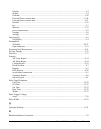
824 reference manual iii-i chapter 1 introduction 1-1 about this manual .................................................................................................1-1 special features of the electronic version ........................................................1-3 bookmarks .................
Page 6: Chapter 3
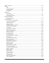
824 reference manual iii-ii pausing measurements..................................................................................2-8 back erasing .................................................................................................2-8 changing the detector of the displayed spl value ......
Page 7: Chapter 4
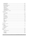
824 reference manual iii-iii memory............................................................................................................3-27 deleting stored data........................................................................................3-29 delete last function .....................
Page 8
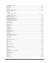
824 reference manual iii-iv ssa displays including 1/1 or 1/3 octave spectral data...........................5-11 tabular ssa views.....................................................................................5-12 time history displays ............................................................
Page 9: Chapter 6
824 reference manual iii-v excd-b display............................................................................................5-53 excd-c display ............................................................................................5-54 excd time history display............................
Page 10
824 reference manual iii-vi common slm settings......................................................................................7-5 title setting - (ssa, log, ism) ....................................................................7-5 detector setting - (ssa, log, ism) ...........................
Page 11
824 reference manual iii-vii spl excd lvl 2 - (log, ssa) .....................................................................7-23 pk excd lvl 1 - (log, ssa) .......................................................................7-24 pk excd lvl 2 - (log, ssa)...........................................
Page 12
824 reference manual iii-viii t.H. Period - (log) ....................................................................................7-41 excd trigger - (log)..................................................................................7-41 excd time - (log) .......................................
Page 13: Chapter 8
824 reference manual iii-ix run log check menu .................................................................................7-75 time history check menu..........................................................................7-76 intervals check menu ...............................................
Page 14: 10-1
824 reference manual iii-x measuring using user-selectable thresholds.......................................................9-17 chapter 10 using the 824 utility software 10-1 824 utility installation ..........................................................................................10-1 star...
Page 15: Chapter 12 Fft (Optional)
824 reference manual iii-xi then settings menu .......................................................................................11-14 trigger settings menu (continued) ................................................................11-14 rt60 reverberation time settings...........................
Page 16: A-1
824 reference manual iii-xii microphone sensitivity calibration......................................................................13-4 aud modes..........................................................................................................13-4 view menu....................................
Page 17
824 reference manual iii-xiii other read commands ...................................................................................A-28 group read programming ..............................................................................A-29 setting commands...........................................
Page 18: B-1
824 reference manual iii-xiv unsupported miscellaneous commands .............................................................A-78 data file commands ...........................................................................................A-79 keyboard simulation ......................................
Page 19: Appendix E Memory Usage
824 reference manual iii-xv microphone guidelines ..............................................................................D-12 near field...................................................................................................D-15 noise...................................................
Page 20: G-1
824 reference manual iii-xvi reference sound pressure level:................................................................. F-1 reference level range: ............................................................................... F-1 microphone reference point:.......................................
Page 21: About This Manual
9/29/09 introduction 1-1 c h a p t e r 1 introduction welcome to the larson davis lxt. This versatile instrument, with graphic display, performs the functions of several instruments. It puts the combined features of a precision sound level meter and a real-time frequency analyzer in the palm of your...
Page 22
1-2 824 reference manual 9/29/09 • chapter 5 - system 824 instrument modes: provides descriptions of the system 824’s standard instrument id’s. • chapter 6 - system 824 views: gives you a detailed description of the different display views available and how to access them. • chapter 7- using id sett...
Page 23: Bookmarks
9/29/09 introduction 1-3 • appendix b - serial port remote control interface: explains how to use the serial port interface for remote control of the system 824. • appendix c - technical specifications: gives a listing of acoustic, electronic, environmental, and physical characteristics of the syste...
Page 24
1-4 824 reference manual 9/29/09 screen labeled bookmarks. These will appear as shown below. In the unexpanded view, bookmarks lists the names and page numbers of chapters and appendixes in order of appearance, as well as the table of contents and the index. Closing bookmarks to close bookmarks, sim...
Page 25: Links
9/29/09 introduction 1-5 click to display page left click on any text field (chapter name, appendix name, table of contents, index, or any sub heading) and the page displayed on the right will jump to the page associated with that text field. Return to previous view to return to the page which was d...
Page 26: About This Chapter
1-6 824 reference manual 9/29/09 previous view" on page 1-5 about this chapter this introductory chapter covers the following topics: • formatting conventions: provides an explanation of the fonts and other formatting conventions used in this manual. • features: gives an overview of the system 824 k...
Page 27: Features
9/29/09 introduction 1-7 features hardware features: the larson davis system 824 has the following features: • large backlit bitmapped graphic display • soft rubber backlit keys • pop-up menus with scroll bars • pick and choose setup...Just click and run! • file management system (stores multiple me...
Page 28
1-8 824 reference manual 9/29/09 • simultaneous measurement of sound pressure level using fast, slow, impulse, peak, and leq detectors with a, c, and flat weighting (ssa, ism, log, and tal instruments) • exceptionally large dynamic range (> 93 db for ssa and > 115 db for ism and log) • digital filte...
Page 29
9/29/09 introduction 1-9 - 12,300 ssa intervals with leq & max 1/3 octave spectra - 60,000 log intervals without ln - 35,000 log intervals with ln - 1,000,000 point time history - 70,000 rta 1/1 octave spectra - 28,000 rta 1/3 octave spectra - 2400 fft 400 line snapshots • ac/dc output, unweighted, ...
Page 30: System 824 Components
1-10 824 reference manual 9/29/09 system 824 components figure 1-1 the system 824 is a convenient hand-held sound level meter with a simple user interface. The standard system 824 shown in figure 1-1 includes the following: • 1/2” diameter condenser microphone • backlit graphic 64 x 128 pixel lcd di...
Page 31
9/29/09 introduction 1-11 figure 1-2 the system 824 has a series of connectors located at the bottom of the device consisting of an ac and dc output connector, control connector, serial interface connector, and external dc power connector. The following is a layout of the control connector, which is...
Page 32
1-12 824 reference manual 9/29/09 7 - calibration control output (0 to +5 volts, active high, 10 k Ω) 8 - heater control output (open drain, +40 vdc max, 100 ma max) 9 - external power input/output (+8 to +15 vdc) the serial connector is used for computer, printer and modem communications: figure 1-...
Page 33: System Diagram
9/29/09 introduction 1-13 note: see the section "ac/dc output" on page 6-5 for more details concerning the ac/dc outputs. Figure 1-5 ac/dc output connector preamplifier input connector the preamplifier input connector accepts the prm902 preamp. System diagram figure 1-6, illustrates the acoustic-to-...
Page 34: Getting Started
1-14 824 reference manual 9/29/09 calculates all of the desired data based on the sampled data (sample rate of 48-51.2 khz). Getting started this section outlines the steps to unpack the system 824. The following topics are covered: • unpacking and inspection • accessories and optional equipment • c...
Page 35
9/29/09 introduction 1-15 mi c pr ea m plif ie r 0-50 db gain fl at , a-wt, c- wt or 10 hz high pass fl at , a-wt, c- wt or 10 h z hi gh pass analo g to di git al c onverter digi tal si gnal pr oc es so r a c /d c out mu x freq uency de te ctio n an al og t o di git al co nv er te r ext ernal power ...
Page 36
1-16 824 reference manual 9/29/09 comments concerning the digital signal processor although the system 824 does have analog flat, a-weight, c-weight and 10 hz high pass filters ahead of the analog to digital convertor, most of the measurements use digital weighting filters created by the digital sig...
Page 37
9/29/09 introduction 1-17 • hard case 15”x19”x7” (ccs001) with foam insert (0860.0077) • windows tm utility software (sww_824_util) • 10 foot microphone extension cable (exa010) • 3 1/2” diameter windscreen (ws001) the 824s is delivered with the following standard accessories (824s pack): • 3 x 1.5 ...
Page 38
1-18 824 reference manual 9/29/09 connecting internal or external power the 824 is shipped with a nimh battery pack installed. The system 824 can be powered using a 3.6 v nimh battery pack, individual alkaline or nimh cells, or an ac power supply adapter. For specifications on operating time under b...
Page 39
9/29/09 introduction 1-19 using alkaline batteries or individual nimh rechargable cells. Use duracell mn 1500 (1.5 volt, 2,850 mah) alkaline battery or equivalent. You may also use the duracell ultra ™ or energizer titanium ™ next generation batteries which may provide up to 40% more run time. To us...
Page 40
1-20 824 reference manual 9/29/09 figure 1-8 battery terminal assembly orientation. Figure 1-9 battery cover and compartment with alkaline batteries and terminal assembly installed. (note location of terminal assembly.) using the ac power adapter you may use an external power source via the external...
Page 41
9/29/09 overview 2-1 c h a p t e r 2 overview this chapter presents a general overview of the structure of the model 824, an example of selecting a setup or instru- ment definition (id), performing a measurement and storing the data. Subsequent chapters will deal specifically with these steps in a m...
Page 42: Slm&rta (Ssa)
2-2 824 reference manual 9/29/09 instrument definition (id) types write protect, delete, write enable ids after an id has been created, it can be protected (or locked), or deleted if necessary. This is described in detail in the section "write protect, delete, write enable ids" on page 3- 17. Slm&rt...
Page 43
9/29/09 overview 2-3 coincident with the maximum value of the sound pressure level during the measurement period. A back erase function allows the removal of up to the last 30 seconds (in one second steps) of data when a disruptive noise occurs. The 824 also provides an automatic measurement and log...
Page 44: Slm (Ism)
2-4 824 reference manual 9/29/09 an interval history which includes 6 l n values (6 values with 0.1 db resolution, based on user-selected percentages with 0.01% resolution). For takt users, as a no-cost option, the following additional parameters are provided: taktmaximal with the following combinat...
Page 45
9/29/09 overview 2-5 the following parameters can be logged at user-selectable time intervals between 1 second and 99 hours (hh:mm:ss) • l max , l min , sel, and l eq (q=3) or time weighted aver- age (q=4, 5, or 6) levels for a selected detector (slow, fast, or impulse) and a selected frequency weig...
Page 46
2-6 824 reference manual 9/29/09 selecting a measurement setup the simplest way to setup the instrument is to select the id which most closely meets the requirements of the measurement to be made and then modify it to meet your specific needs. The instrument is delivered with a number of permanent s...
Page 47
9/29/09 overview 2-7 after selecting a measurement setup, press the s key to initiate the measurement. Step 2 to select the desired setup, scroll through the setup list with the u and d keys until the item is highlighted, then press c . It will be shown later how the setup menu can be utilized to mo...
Page 48
2-8 824 reference manual 9/29/09 the large numerals represent the spl measurement taken with the slow detector and the a-weighting. In the lower left is an indication of the leq value and the elapsed time of the measurement for which the leq value is calculated. The graph being traced across the dis...
Page 49
9/29/09 overview 2-9 step 1 to change to the detector type, use the u or d keys to highlight the slow detector, as shown below: step 2 to scroll through the optional detectors, press the r or l arrow keys. This will display the spl corresponding to the fast and impulse detectors. Go back to the slow...
Page 50
2-10 824 reference manual 9/29/09 changing the displayed secondary parameter step 1 to select the secondary parameter to be displayed (leq in this example), use the u or d keys to highlight the leq label. Step 2 press the r or l arrow keys to display the val- ues of a-weighted sel, lmin, lmax, lpeak...
Page 51: Views
9/29/09 overview 2-11 also be changed from the setup menu, as described later in this manual or it can be changed here. Step 1 to change the gain, use the u or d keys to highlight the gain, as shown below . The gain shifts the dynamic range up or down. See page 5-3. Step 2 use the r or l arrow keys ...
Page 52
2-12 824 reference manual 9/29/09 the view choices for the ssa instrument type are as follows: slm sound level meter parameters, graphic and digital display any data tabular presentation of sound level meter parameters rta live live display of real-time frequency spectrum rta leq display of leq spec...
Page 53: Data Storage and Recall
9/29/09 overview 2-13 as part of this exercise, select each of these various views and use the d and u keys to see how a variety of different parameters are displayed within each function. We have sought only to explain the general concept of the view function at this time. More detailed explanation...
Page 54: Calibration
2-14 824 reference manual 9/29/09 step 2 press the up u and down d arrow keys until the desired file is indicated. Press the check c key, select “recall” from the menu and press the check c key again. Calibration power off the instrument prior to connecting a microphone or preamplifier; the high vol...
Page 55
9/29/09 overview 2-15 step 3 to setup the calibration process, press the r key to move into the calibration menu. Step 4 to set the calibration level, press the d and u keys to highlight “cal level”, note: the output level specified by the calibrator manufacturer will be at standard temperature and ...
Page 56
2-16 824 reference manual 9/29/09 step 8 to verify that the instrument is properly cali- brated, use the u key to highlight “check”. Step 9 place the calibrator over the microphone, switch the calibrator on, and press c to activate the cal- ibration check process. The display will show the measured ...
Page 57
9/29/09 overview 2-17 correction of calibrator output level the cal200 provides a nominal pressure level of 94 db or 114 db. The exact levels are printed on the larson davis calibration sheet that is delivered with the calibrator. The free field level is -0.12 db from either of these levels. If the ...
Page 58
2-18 824 reference manual 9/29/09.
Page 59
9/29/09 front panel keys; functions and menus 3-1 c h a p t e r 3 front panel keys; functions and menus this chapter contains an overview of the functions which are accessed through the system 824 keypad (see figure 3-1 below): figure 3-1 system 824 keypad. The 14 keys on the system 824 keypad are o...
Page 60
3-2 824 reference manual 9/29/09 power key measurement keys navigation keys control keys v power turns on / off the system 824; accesses bat- tery power monitoring and lcd utilities, and is used to close menus. S run/stop begins and ends measurements. P pause pauses readings while running, previews ...
Page 61: Power Key
9/29/09 front panel keys; functions and menus 3-3 note: the reference information in this chapter is organized according to func- tions, rather than by tasks (which can use several functions). The functions and displays associated with the above keys are described next. In addition, relevant referen...
Page 62
3-4 824 reference manual 9/29/09 power-up the instrument / viewing pwr display to turn on the power: step 1 press the v key. Step 2 allow the instrument to stabilize as indicated by the hourglass symbol in the screen’s upper right hand corner. Step 3 as soon as the hour glass icon disappears, the sy...
Page 63
9/29/09 front panel keys; functions and menus 3-5 check menus allow you easy access to system or instrument settings. The u or d arrow keys, allow you to select the desired menu item and by pressing the r key you can make changes to the setting. The settings menu allows you to adjust the contrast (o...
Page 64: Power Settings
3-6 824 reference manual 9/29/09 power settings use the u and d keys to move from one setting to the next. Then use the r key to change the selected setting. The l key is used to return to previous menus. The power menu provides the following menu items: once the smart charger has been activated the...
Page 65
9/29/09 front panel keys; functions and menus 3-7 the power settings menu item provides the following eight settings: menu items available setting options description power off mode blank lcd auto off manual off blank lcd - the instrument lcd display and serial communication port, will turn off afte...
Page 66: Run/stop Key
3-8 824 reference manual 9/29/09 extra notes on power conservation note: to exit the power display, press the left l arrow key or use the view key to the select desired view. If you are using an external power supply, the v key will display the constant voltage coming from the power supply. If the e...
Page 67: Reset Key
9/29/09 front panel keys; functions and menus 3-9 instrument is running, or a box symbol if the instrument is stopped. Note: the indicator box in the upper right hand corner of the display will be solid if data is present, or open if no data has been taken. Repeatedly pressing the s run/stop key aft...
Page 68: Pause Key
3-10 824 reference manual 9/29/09 p pause key the p pausekey has 3 basic functions in the ism and ssa instruments: to pause a measurement to avoid unwanted noise from entering into the measurement data. To erase unwanted data from the measurement and to preview the data coming into the instrument wi...
Page 69: Arrow Keys
9/29/09 front panel keys; functions and menus 3-11 preview pressing the p pausekey when an instrument is “stopped” brings up a preview display which allows you to view the spl without affecting measured data. Pressing the p pausekey again will exit this screen or simply press the s run/stop key to e...
Page 70: Check Key
3-12 824 reference manual 9/29/09 c check key the c key allows you to choose an item from a menu or to confirm the entry of a setting. Pressing c in many displays will bring up a menu from which you can make changes to settings appropriate to that display. V view key the display of data on screen of...
Page 71: Data Key
9/29/09 front panel keys; functions and menus 3-13 d data key the d data key controls the storing and recalling of measurements, or data files from memory. Each file may contain cumulative data, time history, interval history, cali- bration data and histogram tables that can be stored as dis- tinct ...
Page 72: Setup Key
3-14 824 reference manual 9/29/09 to move from one record to another, use the u or d keys. To exit the data files view, press the l to return to the previous display or select a new view using the v view key. Pressing the c key from the data files display, brings up a menu that allows you to recall ...
Page 73
9/29/09 front panel keys; functions and menus 3-15 define a project id on a computer using the 824 utility soft- ware and then install it into the instrument where it may be selected for use. For example, one project may require the “simple slm” where no data logging is performed and the weighting a...
Page 74
3-16 824 reference manual 9/29/09 : save id the save id menu item saves or creates an id. Use the u or d keys to highlight save id, then press c . You will then be prompted to verify the name for the id. (see id name below) title you can attach a description to your id with the title menu item. This...
Page 75
9/29/09 front panel keys; functions and menus 3-17 write protect, delete, write enable ids note: within a given active instrument definition (id), write protect or delete operations cannot be performed on files that were stored using that same id. In order to protect or delete these files, the activ...
Page 76: Tools Key
3-18 824 reference manual 9/29/09 t tools key note: in certain situations you also use the t tools key to delete, write enable, or write protect instrument defi- nitions (id) from the setup menu (as previously described). The t tools key allows you to access controls and oper- ations such as calibra...
Page 77
9/29/09 front panel keys; functions and menus 3-19 clock/timer current time current date day of week timer mode run date stop date run time 1 stop time 1 run time 2 stop time 2 a - current time, date, and time of next action b - timer mode status and settings memory delete last purge all data files ...
Page 78: About
3-20 824 reference manual 9/29/09 about to access information about the system 824 use the u or d key to select about from the tools menu, then press the c key. The following screen appears: the about-a display shows the instrument’s model number and serial number as well as the firmware revision nu...
Page 79
9/29/09 front panel keys; functions and menus 3-21 provides 30 alpha/numeric characters, and is used to describe the instrument or the organization to whom it belongs. Title - like the company name field, the title field is capa- ble of holding 30 alpha/numeric characters. It allows you to title the...
Page 80: Calibration
3-22 824 reference manual 9/29/09 the about-c display shows the system’s currently available instruments. Additional instruments can be added to the sys- tem 824 through firmware upgrades as they become avail- able. Checked instruments are installed and available for use. The number of demos used is...
Page 81: Clock/timer
9/29/09 front panel keys; functions and menus 3-23 change - activates the calibration change (adjust) process. Cal level - enables the user to enter the sound pressure level generated by the calibrator. Calibrator s/n - enables the user to record the serial num- ber of the calibrator (for reference)...
Page 82
3-24 824 reference manual 9/29/09 the r key. A screen similar to the following will appear: with the clock / timer menu you set the instrument's clock/ calendar and timer. The first three menu items allow you to set the current time, date, and day respectively, while the remaining items (run/stop da...
Page 83
9/29/09 front panel keys; functions and menus 3-25 day of week - allows you to change the current day of the week. Use the u or d key to highlight the desired day, then press the c key to select. Timer mode - the timer is used when you want to have the 824 automatically turn on, gather data, and sto...
Page 84
3-26 824 reference manual 9/29/09 block - the timer will automatically turn the instrument on and initiate a single measurement beginning at a certain time on one day and ending at a certain time on the same or another day. Note: if the run time is later than the stop time, then a measurement will s...
Page 85: Memory
9/29/09 front panel keys; functions and menus 3-27 note: if you have selected the block, 1/day or 2/day mode, the timer will automatically turn the instrument on one minute prior to the run time. Run time 2 / stop time 2 - these settings are used to spec- ify a second measurement’s beginning and end...
Page 86
3-28 824 reference manual 9/29/09 for detailed information on the usage of memory (e.G. Bytes for each type of record stored), see "memory usage" on page e-1 the memory-a display shows the amount of memory avail- able for storing data. This information is given both in bytes and as a percentage of t...
Page 87: Deleting Stored Data
9/29/09 front panel keys; functions and menus 3-29 the default value of this setting is 10 allocated setup registers (which uses 5120 bytes of memory). The system 824 has ten permanent id registers. These pre-defined id registers cannot be changed or deleted and do not reduce the amount of data memo...
Page 88
3-30 824 reference manual 9/29/09 that each record points to the next record and the previous record. This structure makes the memory very efficient (compared to fixed sector, file allocation table based mem- ory structures) and sequential forward and reverse data retrieval is very fast. This memory...
Page 89
9/29/09 front panel keys; functions and menus 3-31 recorded for, the bytes used by that record and how much memory is available. Step 4 press the check c key to delete this file. The fol- lowing menu will appear: step 5 highlight “delete” and press the check c key. The record is deleted. If the last...
Page 90
3-32 824 reference manual 9/29/09 step 2 press the tools t key and the following appears: step 3 highlight “memory” and press the right r arrow key to access the “delete last” function. Step 4 highlight “delete last” and press the check c key. The records will appear one at a time. Below are example...
Page 91: Power Monitor
9/29/09 front panel keys; functions and menus 3-33 with “delete” highlighted, press the check c key again to delete the record. The next record will appear. Continue this process until you have deleted all of records that you don’t want. Power monitor this menu option allows adjustment of the auto-p...
Page 92: Communication
3-34 824 reference manual 9/29/09 communication the communication display shows the status of the serial port (i.E. How many minutes until the standby mode is auto- matically enabled) and the last characters received and trans- mitted and is used when troubleshooting communication problems and as an...
Page 93
9/29/09 front panel keys; functions and menus 3-35 default is set to the value of the last 2 digits of the serial number and can be set within the range of 1 to 100. Serial address - address of instrument. This setting identi- fies the instrument within a network of instruments by assigning it a net...
Page 94
3-36 824 reference manual 9/29/09 dial out mode - the 824 will dial out on an exceedance or an alarm or both. Phone number - the 824 will dial the phone number entered here on the events selected in the dial out mode. Monitor number - the monitor number is used to identify which 824 is being queried...
Page 95: Print Key
9/29/09 front panel keys; functions and menus 3-37 modem init - the modem initialization string is entered here. Initialize - the modem initialization string is sent out the rs232 port. P print key refer to the section "printing reports" on page 8-2 for more information on printing. The p print key ...
Page 96
3-38 824 reference manual 9/29/09 ular data reports can also be printed on virtually any serial printer. The print menu provides the ability to output reports con- taining all the data gathered for the measurement to an attached printer. The main print menu is activated by press- ing the p print key...
Page 97
9/29/09 quick start 4-1 c h a p t e r 4 quick start the system 824 instrument provides simultaneous measure- ments of sound pressure level using fast, slow, impulse, peak and leq detectors with a, c, and flat weighting cover- ing a large dynamic range of greater than 105 db in the log and ism instru...
Page 98
4-2 824 reference manual 9/29/09 this screen displays three lines of user information which may be defined as name and address settings. You can use the 824 utility software to input this information. This display also shows the serial number of the instrument and the firmware version and date. The ...
Page 99
9/29/09 quick start 4-3 step 4 using the d key, highlight the calibration menu item, then press the c key. The following screen appears: note: the output level specified by the calibrator manufacturer will be at stan- dard temperature and pressure. In prac- tice the level is a function of temperatur...
Page 100: High Range Calibration
4-4 824 reference manual 9/29/09 of the display, as shown below, along with the message waitindicating that the calibration process in underway and should not be interupted. Step 9 when the calibration is complete, the message will change to stable, after which the following display will appear to p...
Page 101: Slm&rta Measurements
9/29/09 quick start 4-5 taking measurements and storing data this section provides examples of how to select an instrument id, take a measurement, and store the resulting data. Slm&rta measurements whether using the ssa, ism, or log instrument, the slm is one of the most common functions used in the...
Page 102
4-6 824 reference manual 9/29/09 when changing from one id to another you will be prompted to save your data if you have not already saved it. If you do not save your data at this point, any measurement readings you have taken will be lost. If this is your first time using the system 824 and you hav...
Page 103
9/29/09 quick start 4-7 the screen shows a black box symbol in the upper right hand corner indicating that the instrument is stopped and not taking a measurement. If you attempt to store data while a measurement is still running a warning will be displayed, indicating that the measurement must first...
Page 104
4-8 824 reference manual 9/29/09 viewing rta displays during a measurement while taking measurements you can view the instrument’s different displays. This section provides examples of viewing the ssa instrument’s four rta displays which include: • rta live • rta l eq • rta max • rta min do the foll...
Page 105
9/29/09 quick start 4-9 the rta live screen shows a graphical display of the sound readings over a range of frequencies. The spl for the selected frequency is displayed in the upper left corner. The frequency, as selected by the vertical cursor, is displayed in the lower left corner. As the frequenc...
Page 106
4-10 824 reference manual 9/29/09 the rta max view shows a graphical display of the live spectrum of the maximum broadband level since the last current reset. Step 8 use the r and l arrow keys to change the frequency level being displayed. Step 9 press the d arrow key to change to the rta min view. ...
Page 107: Recalling Stored Data
9/29/09 quick start 4-11 recalling stored data measurement data that has been stored can be recalled for review at any time. To recall a data file, do the following: step 1 press the d data key and a screen similar to the following appears: when recalling a data file, the system 824 will automatical...
Page 108
4-12 824 reference manual 9/29/09 the data files check menu includes the following: selecting and modifying instrument definitions (ids) as explained in the section "system 824 setups or instrument definitions" on page 2-1, the way to prepare the system 824 for a measurement is to select an existing...
Page 109: The Setup Menu
9/29/09 quick start 4-13 the setup menu pressing the s setup key will produce a display similar to the following: the active id the first item in the list is the active id, which will be highlighted. If the user exits from the setup menu by pressing either s (a second time) or l , the instrument is ...
Page 110
4-14 824 reference manual 9/29/09 there is one other possibility which should be mentioned. When a stored data file is recalled, then the id stored with that file becomes the active id. Since the id which was used to perform the measurement at that time may have since been modified or even deleted, ...
Page 111: Menu Scrolling
9/29/09 quick start 4-15 menu scrolling there may be more items in a menu than can be shown in a single display. To the right of any menu window, there will be a vertical window within which there will be vertical bar. If this vertical bar extends from the top to the bottom of the vertical window, t...
Page 112: Write-Protected Ids
4-16 824 reference manual 9/29/09 write-protected ids those with a symbol of a padlock to the left are user-defined ids which have been write-protected. Like the permanent ids, these can be selected, modified and used for a measurement, but the name must be changed when stored. Preparing for a measu...
Page 113: Selecting A Different Id
9/29/09 quick start 4-17 • 3. Select a different id, make it the active id, and mod- ify it as required. Selecting a different id use the d and u keys to highlight the desired id and make it the active id by pressing the c check key. This will activate that id, exit the setup menu, and display the m...
Page 114
4-18 824 reference manual 9/29/09 step 3 if the active id in your instrument is a modified version of the slm&rta (ssa), indicated by an asterisk to the left of the name, highlight “>slm&rta (ssa), press c , and in response to the message “active id has changed. Save?”, use r to highlight “no” and p...
Page 115
9/29/09 quick start 4-19 step 1 use d to highlight slm step 2 press r to produce the slm sub-menu step 3 use d to highlight weighting (note that the present selection is “a”) step 4 press r to open slm weighting selections menu step 5 use d to highlight “flt”.
Page 116
4-20 824 reference manual 9/29/09 step 6 press c to select flt as the new slm weighting for the purpose of continuing with this example later in this chapter, please do not press any keys. Although we will not do this in the present example, we could highlight detector noting that it is presently “s...
Page 117
9/29/09 quick start 4-21 have been taken so far in the example above. In this particular instance, when the r key was used to move from the settings menu to the slm sub-menu and from the slm sub-menu to the selections menu, the item highlighted was not the first in the list. Observe that when c was ...
Page 118
4-22 824 reference manual 9/29/09 highlighted, simply use the u key to highlight the first item in a menu before exiting using the l or r key to exit. If you have been using the arrow keys to move between menus and menu items and you feel you have gotten lost, it is possible that you have entered a ...
Page 119
9/29/09 quick start 4-23 step 1 press the u or d keys to highlight the current rms detector (slow, fast, impl). Step 2 press the l or r key to change the selection. The table below shows how to use the arrow keys to navigate through the settings on the slm display. Ud detector slowr fast rimpulse r ...
Page 120
4-24 824 reference manual 9/29/09.
Page 121
9/29/09 system 824 views 5-1 c h a p t e r 5 system 824 views this chapter introduces you to the various ways of viewing measured data for a particular setup or id of the system 824. Specifically, this chapter covers the following topics: • status icons • general views • slm+rta specific views • log...
Page 122: Status Icons and Indicators
5-2 824 reference manual 9/29/09 status icons and indicators when using the system 824 you will encounter a number of different display views. Each display contains an instrument status icon in the upper right hand corner of the display. This icon changes according to the current state of the instru...
Page 123
9/29/09 system 824 views 5-3 double bar - the instrument is paused. Play symbol - the instrument is ready to run (as soon as stabilization completes). Arrow-under-range/near noise floor indicator -the instrument is under range when the arrow is longer. The instrument is near its noise floor when the...
Page 124: General Views
5-4 824 reference manual 9/29/09 general views the system 824 presents measurement data in both graphical and numerical/text formats for easy comprehension. This section provides an overview of the basic components of these display views. See the chapter "using id setting files" on page 7-1 for deta...
Page 125: Slm Views
9/29/09 system 824 views 5-5 step 3 press the check c key and the desired view will appear. Slm views the slm view is available to the ism, ssa, and log instruments. The slm view shows the slm data with a graphic display of time history. In this graphical format, a running time history based upon 1 ...
Page 126
5-6 824 reference manual 9/29/09 the following is a brief description of each of these components: display label - the display label identifies the display. The example above shows the slm view for the slm+rta instrument id. Selected detector - the selection determines which detector’s data (e.G. Fa...
Page 127
9/29/09 system 824 views 5-7 status - status represents the state of the instrument (as described at the beginning of this section). Spl history graph - this shows one second leq readings. The far right bar displays the current spl readings. As readings are taken, they are placed onto the scrolling ...
Page 128: Any Data View
5-8 824 reference manual 9/29/09 any data view the any data view presents a tabular display of slm data in three different formats. • any level format • any impl (impulse) format • any time format the u and d arrow keys allow you to change the any data format you are viewing. The l and r arrow keys ...
Page 129: Ssa Specific Views
9/29/09 system 824 views 5-9 any time format in this view seven different displays present the level, date and time of lmax (fast, slow, and impulse), lmin (fast, slow, and impulse) and lpeak measured with a, c and flat weighting as follows: ssa specific views the system 824 has various displays for...
Page 130
5-10 824 reference manual 9/29/09 available in the ssa instrument; the rta live (instantaneous) spectrum, the rta leq or time weighted averaged (since last reset) spectrum, rta max spectrum, which is the spectrum time coincident with the maximum value of the spl during the measurement interval and r...
Page 131: Ssa Displays
9/29/09 system 824 views 5-11 ssa displays all of the following views can be accessed through the v view key when using the ssa instrument. Additionally, the rta live, rta l eq , rta max and rta min can be easily switched between each other by using the u or d to move to any of the other views. The ...
Page 132
5-12 824 reference manual 9/29/09 to the appropriate position and the frequency readout changes accordingly. Tabular ssa views the tabular display can also be accessed from the main view menu by highlighting the desired rta view, pressing the r arrow key, and then selecting tabular from the submenu ...
Page 133
9/29/09 system 824 views 5-13 select “spectrum” to view the graph again. Time history displays the following are examples of the graphical displays for the slm time history and rta time history views: the up u and down d arrow keys change the record you are viewing. The r or l arrow keys change the ...
Page 134
5-14 824 reference manual 9/29/09 the following are examples of the interval displays: in the leq, max, and min interval displays the cursor position (the vertical bar in the graph) corresponds to the spl level and frequency values on the left side of the display. The up u and down d arrow keys chan...
Page 135
9/29/09 system 824 views 5-15 press the right r arrow key to access the “interval” display menu and highlight “ln spectrum”. Press the right r arrow key to access the “interval” spectral ln displays. The following menu will appear: highlight “spectral” and press the check c key to view the intv-ln(f...
Page 136
5-16 824 reference manual 9/29/09 use the right r and left l arrow keys to move to each one-third octave frequency. To view the spectral 1 through spectral 6 displays (the 6 ln values) use the up u and down d arrow keys. Below is an example of one of these displays: ssa time history the ssa time his...
Page 137
9/29/09 system 824 views 5-17 the slm time history display is shown below: display label leq reading at cursor/ other level selected in th spl history graph time cursor value of other level setup record number status indicator identifies the marker detector setting.
Page 138
5-18 824 reference manual 9/29/09 the following discusses each of these display components: display label - this shows the current display (in this example, “ssa time history”). Leq reading at cursor - displays the current leq of the time history period. This level is also shown graphically. Time cu...
Page 139
9/29/09 system 824 views 5-19 run log see page 6-41 for a description of the run log display. Ln centiles to access the ln displays, press the view v key, use the d key to cursor down and highlight “ln centiles”. Press the right r arrow key to view the ln displays. The following menu will appear: sp...
Page 140
5-20 824 reference manual 9/29/09 the following is a brief description of each of the components of this display: • display label - the display label identifies the display which is the ssa-ln-a display showing six ln percent- ages for an overall measurement. Lns are reset with an overall reset • pe...
Page 141
9/29/09 system 824 views 5-21 • ln graph - graph of ln’s from 1 to 99 (1 being on the left, 99 on the right). There are two levels represented by each bar. The highest of the two are graphed. Spectral lns to return to the ln display menu, press the view v key. To view the spectral lns highlight “spe...
Page 142
5-22 824 reference manual 9/29/09 • percentile values & levels - the ln (percentile levels) level is that level which is exceeded ‘n’ percent of the measurement time for the frequency band. By modifying the six settings, you can select any six percentile values to be displayed. The settings may be c...
Page 143: Logging Slm Specific Views
9/29/09 system 824 views 5-23 use the right r and left l arrow keys to change the frequency band. • selected frequency - level shown at this frequency. • elapsed time - shows the elapsed run time accumulated since the last overall reset. • ln graph - graph of ln for each frequency at the per- centag...
Page 144
5-24 824 reference manual 9/29/09 overall slm an accumulation of data over the entire measurement period and is reset when the entire measurement is reset. Exposure the exposure displays show dose and projected dose, the sound exposure (e) and c-a. Ln centiles display shows six selected l n values, ...
Page 145
9/29/09 system 824 views 5-25 current slm and overall slm views current slm clears and starts over when the r reset button is pressed while running. Overall slm does not clear during a reset, but continues accumulating data. The system 824 contains two independent data buffers that can accumulate da...
Page 146
5-26 824 reference manual 9/29/09 d) peaks e) twa the different views can also be accessed by simply selecting either current or overall slm with the c check key from within the main view menu then cycling through the views with the r and l arrow keys. These displays can be accessed directly from th...
Page 147
9/29/09 system 824 views 5-27 • status • spl history graph the current slm-a or spl display is shown below: the following discusses each of these display components: display label - this shows the current display (in this example, “slm current-a”). The display represents both current-a and overall-a...
Page 148
5-28 824 reference manual 9/29/09 current/overall slm display-b (times) the current / overall-b slm or times display consists of four major components: • display label • start date / time • elapsed time • end date / time the slm current-b or times display is shown below: the following explains each ...
Page 149
9/29/09 system 824 views 5-29 end date/time - date and time the current/overall measurement ended (or current time if still running). Current/overall slm display-c (min/max) the current/overall-c slm or min/max display consists of three major components: • display label • current/overall lmax readin...
Page 150
5-30 824 reference manual 9/29/09 • current / overall flat weighted peak • current / overall c - weighted peak • current / overall a - weighted peak the slm current -d or peaks display is shown below: the following information explains each of the display’s components: display label - shows the disp...
Page 151: Exposure Views
9/29/09 system 824 views 5-31 • sound exposure level • elapsed time the slm current -e or twa display is shown below: the following explains each of the display’s components: display label - this shows the current display (for example, “slm current-e”). The display represents both current and overal...
Page 152
5-32 824 reference manual 9/29/09 exposure display-a the exposure-a display consists of seven major components: • display label • dose • projected dose • time weighted average • sound exposure level • elapsed time the exposure-a display is shown below: the following explains each of the display’s co...
Page 153
9/29/09 system 824 views 5-33 time weighted average - this display shows the time weighted average (twa) measured in db. Sound exposure level - this display shows the sound exposure level (sel) measured in db. Elapsed time - the timer display shows the elapsed run time accumulated since the last ove...
Page 154
5-34 824 reference manual 9/29/09 time weight average - this display shows the time weighted average (twa) measured in db. Sound exposure level - shows the sound exposure level (sel) measured in db. Elapsed time - shows the elapsed run time accumulated since the last overall reset. This is the time ...
Page 155: Ln Centiles Views
9/29/09 system 824 views 5-35 the following explains each of the displays: display label - shows the current display (for example, “slm exposure-c”). C-weighted twa - this display shows the c weighted twa (l eq ) over the duration of the measurement. A-weighted twa -this display shows the a weighted...
Page 156
5-36 824 reference manual 9/29/09 the following explains each of the display’s components: display label - shows the current display (for example, “ln-a”). Percentage settings are entered with a 1/100th db resolution, but are displayed to the nearest 1/10th db when 10 db or greater. Percentile value...
Page 157: Stats Views
9/29/09 system 824 views 5-37 the following explains each of the display’s components: display label - shows the current display (for example, “ln-b centiles”). Current% - selects percentage of ln to display (1 to 99), using the u and d arrow keys to move from one percentile to another. Ln - this di...
Page 158
5-38 824 reference manual 9/29/09 stats-a display the u and d arrow keys cycle between the current slm, overall slm, exposure, ln centiles, and stats views. The stats-a display consists of three major components: • display label • trigger level 1 and event counter • trigger level 2 and event counter...
Page 159
9/29/09 system 824 views 5-39 • display label • peak-i trigger • peak-ii trigger the stats-b display is shown below: the following explains each of the display’s components: display label - this shows the current display (for example, “slm stats-b”). Peak-i trigger - this presents a summary of the n...
Page 160: Run Log (Log & Ssa)
5-40 824 reference manual 9/29/09 the stats-c display is shown below: the following explains the display’s components: display label - this shows the current display (for example, “slm stats-c”). Overload message - the “stats-c”display indicates the occurrence of instrument overloads during the meas...
Page 161
9/29/09 system 824 views 5-41 • run / stop indicator the run log display is shown below for the log and ssa instruments: the following explains this display’s components: display label - shows the display currently being used (for example, “run log”). Log number- the “run log”display shows the start...
Page 162: Time History
5-42 824 reference manual 9/29/09 time history with the time history view you can graphically scroll through and view the spl readings at different points of time in the measurement readings currently active in memory. You can access the time history display by selecting time history with the c chec...
Page 163
9/29/09 system 824 views 5-43 pause - indicates the measurement paused at this time. Cont - indicates the measurement continued at this time. Mark - indicates a marker was set at this point in time. Time cursor- the time cursor (the vertical bar) allows you to scroll graphically through the history ...
Page 164: Intervals
5-44 824 reference manual 9/29/09 intervals the u and d arrow keys show different intervals in history. The l and r arrow keys cycle you through the different interval screens. The intervals view shows a record of various sound pressure data gathered in time segments over a set period of time. An ex...
Page 165
9/29/09 system 824 views 5-45 • leq reading • sel reading • interval duration the interval-a display is shown below for the log and ssa instruments: the following explains each of the display’s components: display label - this shows the current display (for example, “interval-a”). Interval number- t...
Page 166
5-46 824 reference manual 9/29/09 interval duration - the interval duration shows the length of time of the currently displayed interval. Intervals-b display the interval-b display consists of six major components: • display label • interval number • interval date / time • lmax reading • lmin readin...
Page 167
9/29/09 system 824 views 5-47 lmin reading - the lmin reading shows the lmin for the currently displayed interval. Lmax reading - the lmax readingshows the lmax for the currently displayed interval. Interval duration - theinterval duration shows the length of time of the currently displayed interval...
Page 168
5-48 824 reference manual 9/29/09 interval number- the interval numberdisplay shows each measurement interval in the order that it occurred. The interval number indicates the order of the displayed interval in relation to the other interval records. Interval date/time - theevent date/time shows the ...
Page 169
9/29/09 system 824 views 5-49 the following explains each of the display’s components: display label - this shows the current display (for example, “interval-d”). Interval number- the interval numberdisplay shows each measurement interval in the order that it occurred. The interval number indicates ...
Page 170
5-50 824 reference manual 9/29/09 the following explains each of the display’s components: display label - this shows the current display (for example, “interval-e”). Interval number - the “interval number”display shows each measurement interval in the order that it occurred. The interval number ind...
Page 171
9/29/09 system 824 views 5-51 : the following explains each of the display’s components: display label - this shows the current display (for example, “interval-f wind”). Interval number - the “interval number”display shows each measurement interval in the order that it occurred. The interval number ...
Page 172: Exceedance History
5-52 824 reference manual 9/29/09 exceedance history event recording begins when any one of the three following conditions is satisfied: • the instantaneous sound pressure level, lp, exceeds the value of spl exceedance level 1 set by the user. • the instantaneous peak level pk-1, exceeds the value o...
Page 173
9/29/09 system 824 views 5-53 the following explains each of the display’s components: display label - this shows the current display (for example, “excd-a”) exceedance number - the “exceedance” display shows each exceedance record in the order that it occurred. The exceedance number indicates the o...
Page 174
5-54 824 reference manual 9/29/09 • max reading the excd-b display is shown below: the following explains each of the display’s components: display label - this shows the current display (for example, “excd-b”) exceedance number - the “exceedance” display shows each exceedance record in the order th...
Page 175
9/29/09 system 824 views 5-55 • maximum windspeed • direction of maximum windspeed • maximum reading the following explains each of the display’s components: display label - this shows the current display (for example, “excd-c wind”) exceedance number - the “exceedance” display shows each exceedance...
Page 176
5-56 824 reference manual 9/29/09 “excd history” settings via the setup s key. An exceedance time history will be recorded for every exceedance record. An exceedance time history will only be recorded when all of the criteria have been met such as: • spl exceedance level i • minimum duration while d...
Page 177
9/29/09 system 824 views 5-57 the following explains each of the display’s components: display label - this shows the current display (for example, “excd-th”) current record - the “excd-th” display shows each exceedance record in the order that it occurred. This number shows that you are viewing the...
Page 178: Daily Views
5-58 824 reference manual 9/29/09 the exceedance time history includes 10 samples preceding the event and 10 samples after the event. The maximum number of samples that can be stored are 128. In this case only the first 128 samples are stored including the 10 pre-event samples. Graph of exceedance t...
Page 179
9/29/09 system 824 views 5-59 the following explains each of the display’s components: display label - this shows the current display (for example, “daily-a”). If the 824 is started at 1900 hours, the first daily record will run from 1900 hours to 0000 hours and then a new day (daily record) will be...
Page 180
5-60 824 reference manual 9/29/09 maximum and minimum levels - this shows the maximum and minimum levels during this day’s measurements. Peak level - this shows the peak level during the day with different weighting applied. Daily-b display the daily-b display consists of 4 major components: • displ...
Page 181
9/29/09 system 824 views 5-61 ln percentiles - the l n (percentile levels) level is that level which is exceeded ‘n’ percent of the measurement time. You can select any six percentile values to be calculated and stored with the daily record. Daily-c wind display the daily-c wind display consists of ...
Page 182
5-62 824 reference manual 9/29/09 of the displayed daily record in relation to the other records. A new daily record is created each new day. A day is defined as 12:00 midnight to 12:00 midnight. Duration - the duration shows the length of time represented by this daily view (measurement may have be...
Page 183
9/29/09 system 824 views 5-63 the following explains each of the display’s components: display label -this shows the current display (for example, “daily-d wind”). Record number - each “daily” record is shown in the order that it occurred. The record number indicates the order of the displayed daily...
Page 184
5-64 824 reference manual 9/29/09 • display label • date • record number • hourly leq reading • exceedance leq • background leq • partial hour indicator • hourly leq graph the hourly leq display is shown below: the following explains each of the display’s components: display label - this shows the c...
Page 185: Metrics
9/29/09 system 824 views 5-65 background leq - the background leq is the hourly leq minus the exceedance leq. Hour indicator - the hour indicator shows which hour of the day is being displayed. A “p” following the hour indicator means that the measurement was not for a full hour. Hourly leq graph - ...
Page 186
5-66 824 reference manual 9/29/09 the following explains each of the display’s components: display label - this shows the current display (for example, “metrics-a”). Leq reading- this display shows the average level over the elasped time. Dnl reading - the dnl (day-night average sound level) display...
Page 187: Passby
9/29/09 system 824 views 5-67 • elapsed time the metric -b display is shown below: the following explains each of the display’s components: display label - this shows the current display (for example, “metrics-b”). L eq reading - this shows the level of a constant sound over a specific time period t...
Page 188
5-68 824 reference manual 9/29/09 the passby display consists of six major components: • display label • l eq reading • sel reading • max reading • date/time • elapsed time the passby display is shown below: the following explains each of the display’s components: display label - this shows the curr...
Page 189: Wind/tach
9/29/09 system 824 views 5-69 elapsed time - this shows the elapsed time between the 10db down points prior to and following the maximum level measured. Note: the passby triggering system can be used to create an exceedance record of each passby; set “excd trigger” to [passby]. Wind/tach the u and d...
Page 190
5-70 824 reference manual 9/29/09 the following explains each of the display’s components: display label - this shows the current display (for example, “wind-a”). Sound pressure level - this displays the instantaneous sound pressure level windspeed - this displays the instantaneous windspeed. Wind d...
Page 191
9/29/09 system 824 views 5-71 the following explains each of the display’s components: display label - this shows the current display (for example, “wind-b”). Live windspeed and direction- this displays the instantaneous value of windspeed and direction. Average windspeed - this displays the average...
Page 192
5-72 824 reference manual 9/29/09 • display label • live windspeed • live wind direction • percent windy condition • windy directional distribution the following explains each of the display’s components: display label -this shows the current display (in this case, “wind -c percent”). Live windspeed...
Page 193
9/29/09 system 824 views 5-73 see that winds having levels above the windy threshold level of 5.04 (shown on the windy-b view) were from the north west 59% of the time..
Page 194
5-74 824 reference manual 9/29/09.
Page 195
9/29/09 system 824 virtual instruments 6-1 c h a p t e r 6 system 824 virtual instruments system 824 virtual instruments the system 824 presents a number of distinct “virtual instruments” enabling you to select the mode best suited to a particular application. You can, of course, create new setups f...
Page 196
6-2 824 reference manual 9/29/09 the table below describes the basic functions of each configuration. This chapter will discuss how to select an id in addition to providing an explanation of the features of the currently available ids. Instrument 824s 824l 824a 824 824- rta 824- fft 824- aud 824- ta...
Page 197: Selecting An Instrument Id
9/29/09 system 824 virtual instruments 6-3 selecting an instrument id to select one of the system 824 instrument setups or ids, do the following: there will be a ‘>’ to the left of the currently enabled instrument id. The current id will generally also remain at the top of the list. If the user chan...
Page 198: Ssa Measuring Ranges
6-4 824 reference manual 9/29/09 with this instrument the slm and rta functions are operating simultaneously. The primary indicator range of the slm function is 80 dba, sufficient for most applications. In operation, the instrument measures four sets of frequency spectra; the running instantaneous s...
Page 199: Percentiles (Spectral)
9/29/09 system 824 virtual instruments 6-5 377b41 microphone which has 44.1 mv/pa sensitivity. L n percentiles (spectral) the system 824 l n centiles feature provides a display showing the six ln values of one selected 1/3 octave filter. It also displays spectra for the six ln percentiles. Ac/dc out...
Page 200
6-6 824 reference manual 9/29/09 the two possible output signals are on the tip and the ring of the 3.5mm jack. The sleeve is ground. The selection in the 824 controls settings lists the signal output on the tip first, followed by the signal output on the ring. The ac output signal is always amplifi...
Page 201: Logging Slm
9/29/09 system 824 virtual instruments 6-7 the dc output is generated digitally from the spl but is slower than the slow or fast detector response with an exponential time constant of approximately 2.25 seconds. For the aud instrument, ac-1 is on the tip and the dc output is not used. For the rta in...
Page 202: Exceedances
6-8 824 reference manual 9/29/09 • l peak level corresponding to the frequency weighting selected for l eq (see above) and a second l peak level cor- responding to one of the two alternative choices of fre- quency weighting. • l n (6 values with 0.1 db resolution, based on user- selected percentages...
Page 203: Sound Exposure
9/29/09 system 824 virtual instruments 6-9 sound exposure the system 824 lets you set the criteria level and criterion time for dosimetry measurements. A 100% dose occurs if a person is exposed to a constant sound field with a spl equal to the criterion level, for the criterion time or full dose hou...
Page 204
6-10 824 reference manual 9/29/09 note: ranges are in db spl using a typical 377b41 microphone with 44.1 mv/pa sensitivity. See "rms measurement range (log and ism modes only)" on page c-11 for more 824 specifications. The log and ism instruments have a dynamic range of 105 db..
Page 205: Recalling Id Setting Files
9/29/09 using id setting files 7-1 c h a p t e r 7 using id setting files the system 824 makes it easy to make the measurements you need through stored instrument definitions (id). You can select one of the permanent id’s or you can create your own library using the 824’s keypad or the 824 utility s...
Page 206: Customizing Settings
7-2 824 reference manual 9/29/09 permanent id’s are a good starting point for creating your own custom id. If you have taken data that has not been stored or if the instrument is not reset, you will be prompted with “data not saved. Save?”. Answer yes to save the data, no to have the data reset or c...
Page 207
9/29/09 using id setting files 7-3 if you have not already saved your data, you will be prompted to save it at this step. Step 2 select slm&rta ssa from the menu by using the u or d keys and then pressing the c check key. The slm+rta screen appears: the system 824 is now set to the slm&rta (ssa) ins...
Page 208: Settings Descriptions
7-4 824 reference manual 9/29/09 step 5 using the u or d keys, highlight the slm option and press the c check key. Step 6 use the u or d keys to highlight the detec- tor setting, then press the r key or the c check key. The detector settings menu appears: step 7 in the pop-up windows use the u or d ...
Page 209: Common Slm Settings
9/29/09 using id setting files 7-5 • “log and ssa time history settings” • “logging slm interval settings” • “logging slm exceedance history settings” • “logging slm daily history settings” • “logging slm define report settings” in the following sections, headings for each setting or display mode wi...
Page 210
7-6 824 reference manual 9/29/09 there are certain features (such as event counting) that function only with one selection of frequency weighting and one selection of detector, both user selected. These same weighting and detector selections also determine the metrics used for features such as l n ,...
Page 211
9/29/09 using id setting files 7-7 note: if gain is set to -10 or -20 db and the microphone type is not condenser then the gain is set to 0 db and the warning “setting conflict” is displayed. -20, -10, 0, +10, +20, +30, +40, +50 use the u and d keys to highlight the desired value of gain and press c...
Page 212
7-8 824 reference manual 9/29/09 note: the range setting is not meant to be switched dynamically in real time—in part because selecting the “high” option requires a stabilization period. Furthermore, the system 824’s large dynamic range (110db) often makes dynamic range switching unnecessary. The ra...
Page 213
9/29/09 using id setting files 7-9 see "random incidence microphone correction" on page c-24 for the random incidence correction filter’s response. No - random incidence correction is turned off. Yes - random incidence correction is turned on. Note: interval spectral lns will not be available when r...
Page 214: Common Control Settings
7-10 824 reference manual 9/29/09 rta weighting - (ssa) the rta weighting setting allows you to display an a, c, or flat weighted spectrum. An overall reset is required before this parameter can be changed. A - display’s an a weighted spectrum c - display’s a c weighted spectrum flt - display’s a fl...
Page 215
9/29/09 using id setting files 7-11 control settings _(ssa, log) for the ssa and logging instrument, the control settings are also accessed through the “edit settings” menu, except that the last selectable menu item is advanced. Using the u and d arrow keys, highlight the controls item, then select ...
Page 216
7-12 824 reference manual 9/29/09 ac/dc output settings - (ssa, log, ism) the ac/dc output on the 824 allows the user to select what type of signal will be sent out the 3.5mm connector at the base of the instrument. See the section "ac/dc output" on page 6-5 for more details. Logic input setting - (...
Page 217
9/29/09 using id setting files 7-13 to +5 volt logic signal (input load impedance is 100k ohms). The resulting logical state (high or low) will determine what occurs inside the instrument as a function of this logic input setting. Accordingly, the setting provides the following five options: none - ...
Page 218
7-14 824 reference manual 9/29/09 note: in many of the options below, notice the use of a shorthand identifier which includes the first letters of the various events along with the plus + symbol. The plus symbol indicates a logical “or” function between events. In other words, if for a given option,...
Page 219
9/29/09 using id setting files 7-15 p+a - the logic output turns on when a peak exceedance event occurs or when an event occurs on one of the a:d channels. R+p+a - the logic output turns on when either an rms or peak exceedance event occurs or when an event occurs on one of the a:d channels. I+a - t...
Page 220
7-16 824 reference manual 9/29/09 note: if set below 5 seconds, the output will remain “on” as long as the conditions are true, and turn “off” x seconds (0 to 5) after the condition; if set to 6 seconds or greater, the output will stay “on” for at least 5 seconds but will turn “off” as soon as the c...
Page 221: Logging Slm Twa Settings
9/29/09 using id setting files 7-17 logging slm twa settings the time weighted average (twa) settings are available to the logging slm (log) instrument. In a few cases, the ism instrument also provides access to a few of the twa settings. Use the u and d keys to move from one setting to the next. Th...
Page 222
7-18 824 reference manual 9/29/09 exposure level every time the exposure duration is cut in half. This setting provides the following four options: the formulas for twa can be found in "integrated level calculations" on page b-1. 3db - the default 3db option is the most commonly used and results in ...
Page 223
9/29/09 using id setting files 7-19 0 to 255 db exposures at higher levels than the overall criterion level will result in a 100% dose in less time; or, if exposure continues, the overall dose will exceed 100%. Criterion time - (log) the criterion time determines how long exposure to the set twa lev...
Page 224: Log and Ssa Ln Settings
7-20 824 reference manual 9/29/09 crnt threshold (ssa, ism, log) in the ism instrument the crnt threshold setting is a submenu to the slm menu selection. The crnt threshold sets the threshold for computing the current time weighted average (twa). This setting affects the system 824’s secondary or cu...
Page 225
9/29/09 using id setting files 7-21 use the u and d keys to move from one setting to the next. Then use the r key to change the selected setting. The l key is used to return to previous menus. The following is a table of the l n settings: note: an ln percentage of 0 provides lmax for the ln level. E...
Page 226
7-22 824 reference manual 9/29/09 ln’s the l n centiles set the six percentile values to be measured, logged (if selected) and shown in the ln displays. Using these six settings, you can select any six percentile values. As shown above, these settings can each take on any value within the following ...
Page 227
9/29/09 using id setting files 7-23 log and ssa triggering settings for the ssa instrument, these trigger settings are used to control the logic output line. Trigger levels can be set as follows: two for the spl (rms value) and one each for peak i and peak ii. These levels are used with the log inst...
Page 228
7-24 824 reference manual 9/29/09 measurement is reset. A special flag is set with all exceedance records whose l max is greater that this level. This setting can take on any integer value within the following range: 0 to 255 db pk excd lvl 1 - (log, ssa) the pk excd lvl 1 sets the trigger level for...
Page 229
9/29/09 using id setting files 7-25 this setting can include any integer value within the following range: 0 to 9db log and ssa wind/tach settings other transducers providing similar pulse trains and dc voltages representing measured parameters could also be utilized in this manner. For example, eng...
Page 230
7-26 824 reference manual 9/29/09 the wind/tach feature requires the optional firmware 824-wnd. If it is not installed, attempting a setup will display the message shown to the right. . Setup of wind/tach function with either the log or ssa instrument active, press the s setup key to access the “edi...
Page 231
9/29/09 using id setting files 7-27 wind scale wind scaleis a scale factor which provides the wind speed (tach) when multiplied by the frequency of the wind speed (tach) signal from the external transducer. Limits to parameters associated with this factor are as follows: direction unit compass degre...
Page 232
7-28 824 reference manual 9/29/09 examples: wind units wind units is a four character alphanumeric field (e.G. Mph, m/s, ft/s, etc.) direction units direction units. Are used for describing wind direction or throttle position. There are five options available. Compass compass reports wind direction ...
Page 233
9/29/09 using id setting files 7-29 wind/tach enable note that when the wind/tach feature is enabled, ln will automatically be enabled as well. When this occurs, the message “setting conflict” will be shown. Select yes to enable the wind/tach function. If disabled by selecting no, wind/tach data wil...
Page 234
7-30 824 reference manual 9/29/09 wind pause enable select yes to enable the wind pause function. This will cause the system 824 to pause sampling of the input signal whenever the wind speed is above the wind exceedance level. Select no to disable this function. Pulse trigger voltage select 0.0 v fo...
Page 235
9/29/09 using id setting files 7-31 use the u and d keys to move from one setting to the next. Then use the r key to change the selected setting. The l key is used to return to previous menus. The following tables show the time history settings for the log and ssa instruments. Each setting is descri...
Page 236
7-32 824 reference manual 9/29/09 hist enable - (log, ssa) this setting provides the following two options: no - time history storage is disabled. Yes - time history storage is enabled. Menu items ( ssa instrument) available settings options hist enable no yes hist period 1 to 255 period units 1/32s...
Page 237
9/29/09 using id setting files 7-33 hist period (log, ssa) this setting is used in conjunction with the “period units setting” (below). Hist period sets the number of history period units that transpire between successive time history samples. These samples continue either until the instrument is st...
Page 238
7-34 824 reference manual 9/29/09 none - the instrument stores the l eq but does not store a second level. Pk-i - the second level the instrument stores is the greatest instantaneous level (l pk ) detected by the pri- mary peak detector that occurred during the time his- tory period. The primary pea...
Page 239
9/29/09 using id setting files 7-35 advanced time history - (log, ssa) up to 40 different parameters can be stored (log and ssa) with each time history period including wind/tach data and spectral data (ssa only). These are all user selectable in the advanced time history displays. The advanced time...
Page 240
7-36 824 reference manual 9/29/09 marker can be assigned an 8 character description. See page 7-55 for a description of the marker display. Log and ssa interval settings interval settings are available on the log and ssa instruments. The intervals menu sets the system 824 to automatically store at r...
Page 241
9/29/09 using id setting files 7-37 to store interval spectral ln levels, set “spectral ln” to “interval”, enable ln and interval histories and set “intv save ln” to “yes”. Intv enable - (log, ssa) intv enable enables or disables the automatic storage of interval statistical records. This setting pr...
Page 242
7-38 824 reference manual 9/29/09 the real-time of day clock. This synchronization can occur on a 1, 5, 10, 15, 20, 30, or 60 minute basis. The intv period setting should also be set accordingly so that the synchronization works properly. When you start a measurement, the initial storage interval wi...
Page 243
9/29/09 using id setting files 7-39 intv threshold - (log, ssa) intv threshold sets the threshold for computing the interval time weighted average (twa). As per the requirements of various regulatory agencies, only those sound levels which are above a certain threshold level are used when computing ...
Page 244
7-40 824 reference manual 9/29/09 spectra and one other spectra. This setting provides the following three options: none - does not store any spectral data besides the leq spectra with the interval. @max - stores the spectra associated with the maxi- mum broadband level during the interval period. M...
Page 245
9/29/09 using id setting files 7-41 excd time hist - (log) the excd time hist setting enables you to indicate whether or not to have an exceedance time history saved as part of the exceedance. This setting provides the following two options: yes - the exceedance time history will be saved. No - the ...
Page 246
7-42 824 reference manual 9/29/09 daily history settings are only available to the logging slm (log) instrument. The model 824 automatically calculates daily sound statistics including: l eq 24, l dn , cnel, l peak , l uwpk , ln’s, l max , and l min ; and for each hour of the day the hourly l eq , t...
Page 247
9/29/09 using id setting files 7-43 use the u and d keys to move from one setting to the next. Then use the r key to change the selected setting. The l key is used to return to previous menus. The following is a table of the define report settings. Each setting is described later in greater detail. ...
Page 248
7-44 824 reference manual 9/29/09 spl histogram - (log) spl histogram either enables or disables the printing of the spl histogram report. The histogram report contains a histogram of the spl levels that have occurred during the overall and current measurements. The report also prints a table of all...
Page 249: Menu Layout of Ssa Settings
9/29/09 using id setting files 7-45 long - the “long” interval report (including l max , l min , sel, l eq , pk-i, pk-ii, overloads, exceedances, and six ln percentiles) will print. Hist report - (log, ssa) the hist report either enables or disables the printing of the time history report. The histo...
Page 250
7-46 824 reference manual 9/29/09 slm detector slow fast impl weighting a c flt gain a c flt transducer condnsr elctret direct random corr no yes pk weighting a c flt rta rta detector slow fast rta weighting a c flt bandwidth 1/1 1/3.
Page 251
9/29/09 using id setting files 7-47 intervals intv enable no yes intv period hh:mm:ss intv time sync no yes intv save ln’s no yes intv auto stop no yes intv threshold 0 - 255 db intv exchange 3db 4db 5db 6db intv spectrum none @max min.
Page 252
7-48 824 reference manual 9/29/09 time history hist enable no yes hist period 0 - 255 (default: 60) period units 1/32s 1.0s 10.0s 60.0s resolution 0.1db 1.0db th setup activates a set of 3 displays used to configure what time history data will be stored. See the section "advanced time history - (log...
Page 253
9/29/09 using id setting files 7-49 ln enable no yes start level 0-99db (default 15db) ln 1 percent selectable (default: 1.67%) ln 2 percent selectable (default: 8.33%) ln 3 percent selectable (default: 33.33%) ln 4 percent selectable (default: 50%) ln 5 percent selectable (default: 66.67%) ln 6 per...
Page 254
7-50 824 reference manual 9/29/09 menu layout of integrating slm (ism) settings the integrating slm (ism) edit settings menu has 16 configurable items. Provided in this section is a table depicting the menu layout of the ism instrument’s standard settings. Ism setting menu items submenu available se...
Page 255
9/29/09 using id setting files 7-51 slm detector slow fast impl weighting a c flt range normal low high transducer condnsr elctret direct random corr no yes pk weighting a c flt crnt exchange 3db 4db 5db 6db crnt threshold 0 - 255 db advanced see "advanced menu layout" on page 7-56.
Page 256
7-52 824 reference manual 9/29/09 menu layout of logging slm settings the logging slm (log) edit settings menu has 66 configurable items. Provided in this section is a table depicting the menu layout of the log instrument’s standard settings. Log settings menu items submenu available settings option...
Page 257
9/29/09 using id setting files 7-53 twa ovll exchange 3db 4db 5db 6db ovll threshold 0 - 255 db (default: 80db) ovll criterion 0 - 255 db (default: 90db) criterion time 0 - 99 hours (default: 8 hours) crnt exchange 3db 4db 5db 6db crnt threshold 0 - 255 db (default: 80db) crnt criterion 0 - 255 db (...
Page 258
7-54 824 reference manual 9/29/09 time history hist enable yes (default) no hist period 0 - 255 (default: 60) period units 1/32s 1s (default) 10s 60s other level none (default) pk-ii pk-i lmax advc resolution 0.1db (default) 1.0db adv th activates a set of 3 displays used to configure what type of t...
Page 259
9/29/09 using id setting files 7-55 intervals intv enable yes (default) no intv period 0-24:0-60:0-60 (hh:mm:ss) intv time sync yes (default) no intv save ln’s yes (default) no intv auto stop yes no (default) intv threshold 0 - 255 db intv exchange 3db (default) 4db 5db 6db excd history triggering s...
Page 260: Advanced Menu Layout
7-56 824 reference manual 9/29/09 advanced menu layout daily history daily enable yes no (default) daily ln’s yes no (default) define report data report yes (default) no advanced see advanced menu (below) menu items submenu available settings options controls (see also "control settings _(ssa, log)"...
Page 261
9/29/09 using id setting files 7-57 controls (continued) logic-out off rms peak r+p intv r+i p+i r+p+i a:d r+a p+a r+p+a i+a r+i+a p+i+a r+p+i+a r/s excd logic-out time 0 - 255 sec logic-out #2 off rms peak r+p intv r+i p+i r+p+i a:d r+a p+a r+p+a i+a r+i+a p+i+a r+p+i+a r/s excd logic-out #2 time 0...
Page 262
7-58 824 reference manual 9/29/09 controls (continued) heater on no yes e. A. Cal tone no yes wind/tach (see also "log and ssa wind/ tach settings" on page 7-25) this is an optional feature requiring the firmware 824-wnd wind scale 0.015 - 255.99 wind units 4 alphanumeric characters direction units ...
Page 263: Check Menus
9/29/09 using id setting files 7-59 check menus in addition to being able to modify an instrument id’s settings through the edit settings item in the setup menu, selected settings can also be modified through what is known as a check menu which is specific to the current display function. The check ...
Page 264: Check Menu Example
7-60 824 reference manual 9/29/09 toggle between a views tabular mode or graphical spectrum mode. This section will present the following: • check menu example • slm check menu options • other ssa check menus • other logging (log) check menus check menu example the check menu is accessed by simply p...
Page 265
9/29/09 using id setting files 7-61 step 2 use the u and d arrow keys to highlight set- tings, then press the c check key or the r arrow key. A menu similar to the following appears: step 3 use the u and d arrow keys to highlight slm, then press the c check key or the r arrow key. A menu similar to ...
Page 266
7-62 824 reference manual 9/29/09 slm check menu options (ssa and log) the check menu’s controls and settings items correspond to those described earlier in the settings descriptions section of this chapter. The slm display check menus for the ssa and log instruments are identical. The following des...
Page 267
9/29/09 using id setting files 7-63 the “mark” display shows the current spl level and a time history of the spl level is shown graphically. This enables you to set a marker in the time history. To set a marker in the time history, press the check c key. The following menu appears: when “set mark” i...
Page 268
7-64 824 reference manual 9/29/09 graph menu there are two graph settings available: graph level may also be changed interactively with the adjust graph display (below). The graph level setting allow you to change the base level of the spl history graph. The following is the possible setting range: ...
Page 269: Other Ssa Check Menus
9/29/09 using id setting files 7-65 settings the settings menu allows you access to the slm settings area that is usually accessed from the setup s key. (this is a shortcut to the slm settings so you can modify the items in the slm menu) note: refer to the settings description section and the indivi...
Page 270
7-66 824 reference manual 9/29/09 following is a chart of the check menu with a description of each menu item: rta check menu the following check menus are accessible from the rta live, rta leq, rta max and rta min views: following is a chart of the check menu with a description of each menu item: m...
Page 271
9/29/09 using id setting files 7-67 intervals check menu the intervals displays have three different check menus depending upon which display you are viewing. When viewing the displays interval-a through interval-e the following menu appears after pressing the check c key: following is a chart of th...
Page 272
7-68 824 reference manual 9/29/09 following is a chart of the “leq spectrum” check menu with a description of each menu item: time history check menu press the check c key while viewing either of the time history displays and the following check menus appear: menu items purpose bytime allows you to ...
Page 273
9/29/09 using id setting files 7-69 following is a chart of the time history check menu with a description of each menu item: run log check menu press the check c key while viewing the run log display and the following check menu appears: menu items purpose broadband/ spectrum allows you to view the...
Page 274
7-70 824 reference manual 9/29/09 following is a chart of the run log check menu with a description of each menu item: ln centiles check menus there are three different check menus contained within the ln centiles views. Press the check c key while viewing the ln centile’s broadband displays and the...
Page 275
9/29/09 using id setting files 7-71 following is a chart of the ln centiles broadband check menu with a description of each menu item: press the check c key while viewing the ln centile’s spectral displays and the following check menu appears: menu items purpose enable ln enables or disables ln data...
Page 276
7-72 824 reference manual 9/29/09 following is a chart of the ln centiles spectral check menu with a description of each menu item: press the check c key while viewing the ln centile’s spectrum displays and the following check menu appears: menu items purpose start level sets the minimum db level to...
Page 277
9/29/09 using id setting files 7-73 other logging (log) check menus see "slm check menu options (ssa and log)" on page 7-62 for a description of the (log) slm check menu. This section presents the log instrument’s available check menus that are in addition to the slm check menu previously described ...
Page 278
7-74 824 reference manual 9/29/09 ln centiles check menu the ln centile view has access to the following check menu: menu items purpose ovll exchange sets the exchange rate that is used to calculate the overall twa. Ovll threshold sets the threshold for computing the overall time weighted average (t...
Page 279
9/29/09 using id setting files 7-75 stats check menu the stats view has access to the following check menu: run log check menu see "run log check menu" on page 7-75 for a description of the run log check menu for the log instrument. Menu items purpose settings modifies the ln percentiles settings fo...
Page 280
7-76 824 reference manual 9/29/09 time history check menu the time history view has access to the following check menu: intervals check menu the intervals view has access to the following check menu: menu items purpose mark puts a marker in the time history record locate allows you to locate a time ...
Page 281
9/29/09 using id setting files 7-77 excd history check menu the excd history displays have two different check menus depending upon which display you are viewing. When viewing the displays excd-a through excd-b the following menu appears after pressing the check c key: following is a chart of the ch...
Page 282
7-78 824 reference manual 9/29/09 following is a chart of the “excd time history” check menu with a description of each menu item: daily history check menu the daily history display has two different check menus, one for the daily data and one for the hourly data. When viewing the daily history the ...
Page 283
9/29/09 using id setting files 7-79 in the “hourly” display press the check c key and the following menu appears: following is a chart of the “hourly history” check menu with a description of each menu item: note: check menus are not available for the metrics , passby , and wind / tach views. Menu i...
Page 284
7-80 824 reference manual 9/29/09.
Page 285
9/29/09 printing a report 8-1 c h a p t e r 8 printing a report the system 824 allows you to print a report from data col- lected during a measurement. This chapter will discuss the following aspects of printing reports: • connecting the 824 to a serial printer • printing reports • defining and prin...
Page 286: Printing Reports
8-2 824 reference manual 9/29/09 step 3 turn on your printer and the system 824. Printing reports step 1 press the d data key and use the recall files menu to recall the measurement record that you want to print. You may not need to recall a file if you want to print something in memory that has not...
Page 287
9/29/09 printing a report 8-3 step 3 use the u and d arrow keys to highlight set- tings, then press the r arrow key or c check key to select it. The following menu appears: depending on your printer configuration you may have to modify the printer settings for printer baud rate and flow control. Use...
Page 288
8-4 824 reference manual 9/29/09 step 4 use the l arrow key to return to the main print menu. You will notice that there is a paper page icon p next to the “summary” menu item. This means that a report will be printed by highlighting “summary” and pressing the check c key. The title printed on your ...
Page 289
9/29/09 printing a report 8-5 defining and printing tailored reports in the system 824, tailored reports are available to the ssa and log instruments. With the system 824, a tailored report setting for each ssa or log instrument id can be created (i.E. Each user can set up their own user-defined pri...
Page 290
8-6 824 reference manual 9/29/09 step 1 press the s setup key to bring up the setup menu. Highlight the edit settings menu item and press r arrow key or the c check key to select it. Step 2 using the u and d arrow keys, highlight the advanced item, then select it using the r arrow key or the c check...
Page 291
9/29/09 printing a report 8-7 step 5 press the p print key to bring up the print menu. For your report to print properly, your printer must be connected as described in "connecting the 824 to a serial printer" on page 8-1 and configured as described in "printing reports" on page 8-2. Step 6 using th...
Page 292
8-8 824 reference manual 9/29/09 step 1 to print from the recall format menu press the p print key. The following screen appears: step 2 use the u and d arrow keys to highlight the recall format menu. Press the c key and the fol- lowing screen appears: step 3 use the u and d arrow keys and select th...
Page 293
9/29/09 printing a report 8-9 summary report template (ssa instrument) report settings lower level report settings description unformatted [no] a dump of all read, query and interval remote commands. Multiple values are comma delimited. Data report [yes] this shows general information such as leq, s...
Page 294
8-10 824 reference manual 9/29/09 histograms highest level (120) selects the highest peak2 histogram level to be printed. Resolution (5.0) selects the peak2 histogram resolution summary report template (ssa instrument) summary report template (log instrument) report settings lower level report setti...
Page 295
9/29/09 printing a report 8-11 tailored report this template shows the default settings for the tailored report. The tailored report uses the settings from the “define report” menu under the s setup key. This allows you to create a custom report for any ssa or log instru- ment id. The tailored repor...
Page 296
8-12 824 reference manual 9/29/09 after selecting the template you can modify it as explained in "printing a custom report" on page 8-23. Tailored report template (ssa instrument) report settings lower level report settings description unformatted [no] a dump of all read, query and interval remote c...
Page 297
9/29/09 printing a report 8-13 histograms lowest level (110) selects the lowest peak1 histogram level to be printed. Highest level (140) selects the highest peak1 histogram level to be printed. Resolution (5.0) selects the peak1 histogram resolution pk-2 histogram [no] you can customize the peak2 hi...
Page 298
8-14 824 reference manual 9/29/09 all, short report this template shows the default settings for the all, short report. The all, short report prints all of the reports. Those reports with a short version are printed in the short form. After selecting the template you can modify it as explained in "p...
Page 299
9/29/09 printing a report 8-15 all, short report template (ssa instrument) report settings lower level report settings description unformatted [no] a dump of all read, query and interval remote commands. Multiple values are comma delimited. Data report [yes] this shows general information such as le...
Page 300
8-16 824 reference manual 9/29/09 histograms highest level (120) selects the highest peak2 histogram level to be printed. Resolution (5.0) selects the peak2 histogram resolution all, short report template (log instrument) report settings lower level report settings description unformatted [no] a dum...
Page 301
9/29/09 printing a report 8-17 all, long report this template shows the default settings for the all, long report. The all, long report prints all of the reports. Those reports with a long version are printed in the long form. After selecting the template, you can modify it as explained in "printing...
Page 302
8-18 824 reference manual 9/29/09 intv report [long] leq, sel, lmin, lmax, peak, uwpk, exceedances, time, date, and duration in the short report. The long reports adds the ln values and spectral lns for the interval period. Hist report [yes] leq for each time history period. Print range intv report ...
Page 303
9/29/09 printing a report 8-19 data report [yes] this shows general information such as leq, sel, dose, projected dose, lmin, lmax, peak, ln’s, exceedance, and calibration logs. Log report [yes] the run/stop log and with the date and time of each run/stop. Setup report [yes] print the settings and t...
Page 304
8-20 824 reference manual 9/29/09 none enabled report when “none enable” is selected from the recall format menu then all of the reports are disabled and will not be printed. This allows you greater ease in printing only a selected number of reports. After selecting this template you can modify it a...
Page 305
9/29/09 printing a report 8-21 histograms spl histogram [no] prints spl histogram and overall spectral ln report. Lowest level (045) selects the lowest spl histogram level to be printed. Highest level (095) selects the highest spl histogram level to be printed. Resolution (5.0) selects the spl histo...
Page 306
8-22 824 reference manual 9/29/09 print range intv report [no] you can customize the interval report by choosing the long or short report. Lowest record (00000) selects the lowest interval record to be printed. Highest record (65535) selects the highest interval record to be printed. Hist report [no...
Page 307: Printing A Custom Report
9/29/09 printing a report 8-23 printing a custom report the ism instrument does not allow printing customized reports. In addition to being able to print your standard reports for data taken with the ssa, log, or rta instruments, you can also further customize your report definitions at print time w...
Page 308
8-24 824 reference manual 9/29/09 the following table shows the available options under the customize menu for the ssa instrument: menu items options unformatted no yes data report no yes setup report no yes intv report no short long hist report no yes print range intv report (no, short, long) -lowe...
Page 309
9/29/09 printing a report 8-25 the following table shows the available options under the customize menu for the log instrument: menu items options unformatted no yes data report no yes log report no yes setup report no yes spl histogram no yes excd report no short long intv report no short long hist...
Page 310
8-26 824 reference manual 9/29/09 note: see the section "summary report template" on page 8-8 descriptions of each report for the ssa and log instru- ments. The following table shows the available options under the customize menu for the rta instrument: print range excd report (no, short, long) -low...
Page 311
9/29/09 printing a report 8-27 autostore rpt no short long the short reportprints the leq, lmax and lmin spectrum. In addition, the bytime spectrums are included in the long report. Lowest record 0 - 65535 the lowest autostore record to print. Highest record 0 - 65535 the highest autostore record to...
Page 312
8-28 824 reference manual 9/29/09.
Page 313: Configuration of The System
9/29/09 performing a sound level measurement 9-1 a p p e n d i x 9 performing a sound level measurement due to the many features of the system 824 and the variety of measurements it is capable of performing, there is a great deal of instructive material in the preceding chapters. In this chapter, to...
Page 314: Selecting A Measurement Id
9-2 824 reference manual 9/29/09 • logging slm (log) measures sound level parameters and automatically stores the data based on a number of different user-configured data logging methodologies such as time history, intervals, exceedance history and daily history). • sound spectrum analyzer (ssa) whi...
Page 315: Calibration
9/29/09 performing a sound level measurement 9-3 editing the microphone parameters the microphone to be used will either be a traditional condenser microphone, which requires a polarization voltage, or it will be an electret (prepolarized) microphone. Further, if it is a free-field microphone and th...
Page 316
9-4 824 reference manual 9/29/09 entering the noise floor values when measuring low levels of sound, substantial errors can occur when the sound level to be measured is near that of the noise floor of the measuring instrument. An accurate measurement is obtained when the measured sound level is at l...
Page 317
9/29/09 performing a sound level measurement 9-5 editing the measurement parameters note: if you are recalling a measurement id which has already been configured for the measurement you wish to perform, then you can skip to the next section. The design of the system 824 permits the simultaneous meas...
Page 318: Sound Level
9-6 824 reference manual 9/29/09 the slm display is shown below although the system 824 measures the sound pressure level using multiple values of detector and frequency weighting, it only displays a single value as shown above. For this parameter, you have a choice of three detectors (averaging tim...
Page 319: Positioning The Meter
9/29/09 performing a sound level measurement 9-7 • a-weight • c-weight • flat the procedure for selecting these parameters is described in section ”customizing settings” on page 7-2, specifically the sections, ”weighting setting - (ssa, log, ism)” on page 7- 6 and ”pk weighting - (ssa, log, ism)” on...
Page 320
9-8 824 reference manual 9/29/09 which can be placed over the microphone and preamplifier as shown below. To install the windscreen, hold the meter in one hand and the windscreen in the other. Insert the microphone/preamplifier assembly into the opening in the windscreen as shown below and slide the...
Page 321: Selecting The Slm Display
9/29/09 performing a sound level measurement 9-9 selecting the slm display for sound level measurement, press the vkey, use the u key to highlight slm and press the c key to obtain the display shown in ”editing the measurement parameters” on page 9-5 selecting the measurement range ism and log modes...
Page 322: Ssa Mode
9-10 824 reference manual 9/29/09 selecting the range setting when the range is highlighted as shown in the above graphic, the range can be toggled between normal and low by pressing the ror lkeys. If the approximate level is known, select the range setting for which that level falls nearest the mid...
Page 323: Performing A Measurement
9/29/09 performing a sound level measurement 9-11 the uor dkey until the highlight is located in the lower right corner of the display as shown below. When the gain setting is highlighted, this can be changed by repeatedly presssing the uor dkey until the desired value of gain appears. Performing a ...
Page 324: Averaging Time
9-12 824 reference manual 9/29/09 after reaching equilibrium with the ambient environment and switching the power on, the elapsed time until the meter may be used to measure the sound level is as follows: • • requiring a polarization voltage. When performing an integrating measurement, the data is a...
Page 325: Linearity Range
9/29/09 performing a sound level measurement 9-13 linearity range when making a measurement, the upper and lower linearity range limits of the instrument for the setting presently in effect are indicated by the dark regions with light numbers as indicated below. Changing the range (ism and log modes...
Page 326: Overload Condition
9-14 824 reference manual 9/29/09 overload and under range conditions overload condition when the input signal is too high, the electronics will overload. This is indicated by a flashing ovld text message, as well as a flashing ol (for overload) in the upper right corner of the display as shown belo...
Page 327: Max, Min and Peak Values
9/29/09 performing a sound level measurement 9-15 directed arrow in the upper right corner of the display as shown below. To avoid this condition, select a lower range (ism or log mode) are a higher value of gain (ssa mode). Max, min and peak values as stated in ”editing the measurement parameters” ...
Page 328: Timer Mode
9-16 824 reference manual 9/29/09 measuring for a preset integration time the system 824 can perform an integrated measurement over a preset time in either the log or ssa mode by making use of the interval measurement feature. For a detailed description of setting up for an interval measurement, see...
Page 329
9/29/09 performing a sound level measurement 9-17 measuring using user-selectable thresholds the system 824 can be setup to measure data associated with exceedance events, defined as instances where the sound pressure level exceeds a user-selected threshold. For a detailed description of setting up ...
Page 330
9-18 824 reference manual 9/29/09.
Page 331: 824 Utility Installation
9/29/09 using the 824 utility software 10-1 c h a p t e r 10 using the 824 utility software the 824 utility software is a powerful tool for use with the system 824 from larson davis. This software will allow you to control, setup, download and translate your 824 measurement data quickly and easily. ...
Page 332: Connecting to Your Computer
10-2 824 reference manual 9/29/09 start and then select the run menu item. A prompt will appear to enter the program name. Enter “e:\824auto.Exe”. A new screen will appear with several menu items to choose from. Select “install software” from the menu items. Another screen will appear with several m...
Page 333
9/29/09 using the 824 utility software 10-3 plugs into the serial port of the 824 and the 9-pin connector plugs into a serial port on your computer. You do not need to be connected to the 824 in order to translate files which have already been downloaded. Before any functions can be performed on the...
Page 334: 824 Utility Tool Bar
10-4 824 reference manual 9/29/09 note: see "communication" on page 3- 34 for details on changing the communication parameters on the 824. Step 6 select the comport that your 824 is connected to, select the baud rate, and press the connect button. After a successful connection, the setup window will...
Page 335
9/29/09 using the 824 utility software 10-5 connect button. This button is used to establish a connection to the 824. Pressing this button will bring up the connect dialog box where the connection parameters can be defined. Retrieve setups from 824. This button will retrieve all current setups in th...
Page 336: 824 Utility Setup Window
10-6 824 reference manual 9/29/09 824 utility setup window the setup window is the default window that will open up when the 824 utility program is started. The setup window will allow you to edit existing setups, retrieve setups from the 824 or a file, create new setups, and store setups to the 824...
Page 337
9/29/09 using the 824 utility software 10-7 824 or a disk file. The settings dialog section will allow you to manipulate the setup. Retrieving setups from the 824 setups stored in the 824 can be retrieved by clicking on the get setup button on the tool bar or by selecting get setups from 824 from th...
Page 338
10-8 824 reference manual 9/29/09 setups will be retrieved from the 824 and will be displayed in the setup listbox. In the list of setup files, the system setup is the first setup and is followed by all of the permanent and user-defined set- ups. In the setup list box, there are several parts of the...
Page 339
9/29/09 using the 824 utility software 10-9 window). The setups are organized and grouped similar to the 824 menu structure in the instrument. Click on the differ- ent tabs to access all of the setup parameters. Modifying and storing setups to the 824 note: if you change settings in the utility prog...
Page 340
10-10 824 reference manual 9/29/09 manipulating a setup to change any of the variables for a particular user defined setup, select the setup. The appropriate setup tab dialog will appear at the right of the setup list box. Select the setting you wish to change and enter the new value..
Page 341
9/29/09 using the 824 utility software 10-11 you can also access several setup functions by right clicking on the setup in the setup list box. The following functions can be accessed by pressing the right mouse button while within the setup list box. The setup menu items will appear enabled or disab...
Page 342: Opening Setup Disk Files
10-12 824 reference manual 9/29/09 saving setups to disk files once you have created or modified a setup, you can store the setup to a file. Select the save setup to a file menu item from the file menu or click on the save to file button on the tool bar. Note: the system setup is automatically updat...
Page 343
9/29/09 using the 824 utility software 10-13 a standard windows open file box will appear. Select the file folder that contains the file and select the setup file you want. The setup appears in the select setup list box. You can then select (highlight) the desired setup in the list. The high- lighte...
Page 344: Creating A New Setup
10-14 824 reference manual 9/29/09 creating a new setup you create new setups by selecting the new setup menu item from the file menu or by selecting the new setup but- ton on the tool bar. From the displayed dialog box, select the type of new setup. Press the ok button and you will now see the new ...
Page 345: Renaming An Existing Setup
9/29/09 using the 824 utility software 10-15 if a message window occurs after pressing the ok button like that shown below, you will have to create a default setup file by following this procedure: • select the permanent setup for the desired instrument type. • under the file menu select “save setup...
Page 346: Deleting An Existing Setup
10-16 824 reference manual 9/29/09 a dialog box will be displayed to allow you to change the name of the selected setup. Enter the new name for the setup, and press the ok button. Note: the permanent setup id’s in the 824 cannot be renamed. After renaming a setup, you can store it to a disk file, or...
Page 347: Locking and Unlocking Setups
9/29/09 using the 824 utility software 10-17 locking and unlocking setups to prevent accidently deleting a user defined setup, right click on the desired setup and select lock setup from the popup menu. Note that if you have just created a new setup, the setup must first be stored to the 824 before ...
Page 348
10-18 824 reference manual 9/29/09 above the measurement list box is a pull down menu listing the possible file types that can be displayed. This allows you to select only the files you want for download. You can also select “all ” which will download all the files in the 824 simultaneously for tran...
Page 349
9/29/09 using the 824 utility software 10-19 window, press the file folder button, next to the directory entry. Note: the 824 utility program will download the files with the date the file was created as the file name as a default. It will also download the file to the 824 utility folder as a defaul...
Page 350
10-20 824 reference manual 9/29/09 changing the download file name to change the name of the downloaded file, enter a new name in the “file name” area. Press the save button to return to the download section of the 824 utility software. Our new file name and the path to the specified directory now s...
Page 351
9/29/09 using the 824 utility software 10-21 adding notes to a download file information can be entered into the note fields provided for each measurement. The information will be tagged onto the translated reports for each measurements. Selecting active measurements or data files there are two type...
Page 352: Downloading The Measurement
10-22 824 reference manual 9/29/09 downloading the measurement the 824 utility software has multiple file download capability by selecting “all ” from the pull down menu and highlighting one or more of the files from the measurement list for download or selecting files of one type and highlighting o...
Page 353
9/29/09 using the 824 utility software 10-23 the download window gives you the following options: • you can save only the binary data and translate the file later, or • you can save the binary data and the selected records from the translated file (saved as .Csv or .Txt), launch a spreadsheet or tex...
Page 354
10-24 824 reference manual 9/29/09 the download status window will appear and report the sta- tus of the download. The next file can now be selected, the destination folder specified, the file name entered, and the data downloaded. A downloaded file will be stored with the file extension slmdl (soun...
Page 355
9/29/09 using the 824 utility software 10-25 the binary files for each virtual instrument (ism, ssa, log, rta, fft, aud, tal) have the following default file designations: the default file name uses the date on which the data was taken. The file name can be changed to any name that you choose. • 28j...
Page 356
10-26 824 reference manual 9/29/09 you use the translate view to select a downloaded file with the file extension.Slmdl to translate and view the desired records from the file on the screen, or to print the desired records from the file. The left portion of the translate window functions as a win- d...
Page 357
9/29/09 using the 824 utility software 10-27 each downloaded file will contain several records, depend- ing on the type of setup used, and the data stored. Selecting a data set to view after the downloaded file is located, click on the data you wish to view. Downloaded measurement file. Data transla...
Page 358
10-28 824 reference manual 9/29/09 the data is displayed on the right side of the screen. If the data record is too large to be effectively displayed in that area, a message will appear at the top of the displayed record indicating that it is available for export only..
Page 359: Printing A Translated File
9/29/09 using the 824 utility software 10-29 printing a translated file to print the translated data, select the file that you wish to print from the translate window . Display the file as described earlier. Select print from the file menu..
Page 360
10-30 824 reference manual 9/29/09 the default windows printer dialog box will be displayed. The report will be printed in a text format similar to that shown below..
Page 361
9/29/09 using the 824 utility software 10-31 viewing a translated file within a spreadsheet program to view the translated data with a spreadsheet program, select the view data in spreadsheet menu item from the file menu or the launch spreadsheet button on the tool bar. When you select the view data...
Page 362: Additional Features
10-32 824 reference manual 9/29/09 once the data is in the spread sheet program it can be manip- ulated, stored, and graphed using the standard spreadsheet functions. You can also export and/or save the translated data to a text file, by selecting the export data menu item from the file menu. Additi...
Page 363
9/29/09 using the 824 utility software 10-33 histogram options window these settings only affect how the data is displayed and not how they are stored. The histogram options window allows more flexibility in viewing the histograms. Here you can set the parameters to fit your particular needs. To acc...
Page 364
10-34 824 reference manual 9/29/09 rt60 select options the 824 utility software can calculate an rt60 for each 1/3 octave frequency from the autostore bytime data taken by the rta instrument. The software gives you the flexibility to set the options for the calculation and display of the rt60 values...
Page 365
9/29/09 using the 824 utility software 10-35 rt60 measurements both the 824 instrument and the 824 utility software round the rt60 values to two decimal places. However, because the 824 uses logarithmic arithmetic to calculate the rt60 value and the 824 utility software uses double precision to calc...
Page 366
10-36 824 reference manual 9/29/09.
Page 367
9/29/09 rta (optional) 11-1 c h a p t e r 11 rta (optional) welcome to the system 824 real-time analysis firmware option. This option adds high speed spectral data gathering to the system 824 and will enable you to perform the following measurements: • architectural acoustics • on-board rt60 analysi...
Page 368: Settings Menu
11-2 824 reference manual 9/29/09 settings menu rooms.Rta is setup to be a 1/1 octave analyzer that takes 10 second measurements for ncb and rc analysis. The settings menu for the rta instrument is accessed from the s setup key. There are three permanent rta instrument definitions (id) available: ro...
Page 369
9/29/09 rta (optional) 11-3 for other information pertaining to the rta instrument, see the following in this manual: • for data storage, see "taking measurements and storing data" on page 4-5. • for printing rta reports, see "printing reports" on page 8-2. • for i/o commands, see "serial port inter...
Page 370
11-4 824 reference manual 9/29/09 the menu layout of the rta settings is shown in the table below: menu items submenu available settings options available settings options title user customized text entry rta gain (db) -20 -10 +0 +10 +20 +30 +40 +50 bandwidth 1/1 1/3 detector lin exp lin detc time 0...
Page 371
9/29/09 rta (optional) 11-5 trigger setup (continued) arm arm mode now l l = l > input time count arm level 0.0 - 255.9 db arm time 00.0000 to 99.9975 sec arm samples 0 - 65535 arm logic in low high trigger trigger mode now l l = l > input time count trigger level 0.0 - 255.9 db trigger time 00.0000...
Page 372: Settings Descriptions
11-6 824 reference manual 9/29/09 settings descriptions title setting use the title setting to create a title or heading for printed reports. This title will be placed at the top of each rta report you print. Rta settings menu gain setting gain adjusts the voltage level delivered to the measuring po...
Page 373
9/29/09 rta (optional) 11-7 • exponential linear detector time the linear detector time will be adjusted to an integer multiple of 0.0025 seconds (2.5ms). Allows the user to select the averaging time when the linear detector is used. Also sets the storage rate for the autostore bytime records. • 0.0...
Page 374: Autostore Settings Menu
11-8 824 reference manual 9/29/09 random correction the random corr setting gives you the option of turning on a digital filter to provide the correction necessary to provide a random incidence response when measuring with a 2540 or 377b41 free-field microphone. See "random incidence microphone corr...
Page 375: Arm Settings Menu
9/29/09 rta (optional) 11-9 save bytime when autostore is turned on, bytime records are automatically stored. This feature allows the user to enable or disable storage of bytime data in an autostore record. With this feature turned off and the autostore function turned on, the 824 will only store le...
Page 376
11-10 824 reference manual 9/29/09 • time - the 824 arms after the “arm time” seconds in the ready mode. • count - the 824 arms after “arm count” samples of data have been received. Arm level arm time is used in conjunction with arm level as a qualifier for the level setting. See example below. This...
Page 377: Trigger Settings Menu
9/29/09 rta (optional) 11-11 trigger settings menu trigger mode the 824 triggers and starts recording an autostore record when armed and the following conditions are met: • now - the 824 starts recording an autostore immedi- ately. • l - when the level is less than the “trigger level” for “trigger t...
Page 378: End Settings Menu
11-12 824 reference manual 9/29/09 time is non-zero, then the level condition must be met for the specified time before the trigger will occur. • 00.0000 to 99.9975 seconds trig samples when the “trigger mode” is set to count; “trig samples” is the number of samples that will be taken before the 824...
Page 379
9/29/09 rta (optional) 11-13 • time - the 824 stops recording an autostore after “end- time”. • count - the 824 stops recording an autostore after “end samples” of data have been received. End level this level is used when the “end mode” is set to level (l l=, l>). It is the amplitude in db at which...
Page 380: Then Settings Menu
11-14 824 reference manual 9/29/09 then settings menu end then after the measurement ends, the 824 may do the following: • stop - the measurement ends. • repeat - the measurement repeats when the arm and trigger settings have been satisfied. A new autostore record is created for each repeated measur...
Page 381
9/29/09 rta (optional) 11-15 • high logic out the logic out bit value determines which lines (heater, cal, or logic) will be used on the control connector to indicate each of the five states. • 0 - 65535 these lines can be used to control lights in a remote control device to indicate the current sta...
Page 382
11-16 824 reference manual 9/29/09 vdc and the maximum current is 100 ma. Return current path is through pin 1, control ground. Rt60 reverberation time settings rt60 db down the automatic rt60 algorithm will search for a point 5 or more db down from the maximum sample and then calculate an rt60 betw...
Page 383
9/29/09 rta (optional) 11-17 rt60-a and rt60-b instrument definition the rt60-a setup is configured for the use of a steady-state noise source which is shut-off to initiate the decay. The rt60-b setup is configured for the use of a noise burst such as a balloon bursting. The system 824 contains two ...
Page 384
11-18 824 reference manual 9/29/09 • then: stop rt60-b the rt60-b setup is designed to measure an rt60 by exciting a room with impulsive noise such as a gunshot or a balloon popping and is configured in the following way: • detector: linear • detector time: 0.01 seconds • autostore: yes • pretrigger...
Page 385: Display Views
9/29/09 rta (optional) 11-19 • bandwidth: 1/1 octave • detector: linear • linear detector time: 00.1000 seconds • autostore: yes • bytime: no • triggering: on • trigger mode: now • end mode: time • end time: 10.0000 seconds • end then: stop display views this next section will explain the various di...
Page 386
11-20 824 reference manual 9/29/09 now press the r right arrow key to bring up the “view rta” display view menu. Use the u up and d down arrow keys to highlight the desired display. The rta display view menu offers 5 choices: live, leq, max, min, and times. Use the c check key to select the live dis...
Page 387
9/29/09 rta (optional) 11-21 leq press the v view key again to display the “view rta” menu. Press the u up and d down arrow keys to highlight the desired display and press the c check key to select the highlighted display. The leq display shows the equivalent level of all the samples. A current or o...
Page 388
11-22 824 reference manual 9/29/09 min once in a display view, you can simply use the u up and d down arrow keys to move between the views. The min spectrum shows the minimum level obtained by each filter along with the minimum broadband (flat) level. This is a bin-by-bin minimum level. The min spec...
Page 389: Trigger Views
9/29/09 rta (optional) 11-23 trigger views the trigger display views are accessed through the v view key. To select the trigger display views press the v view key. The following menu will appear: use the u up and d down arrow keys to highlight “trigger”. Now press the r right arrow key to bring up t...
Page 390
11-24 824 reference manual 9/29/09 setup use the d down arrow key to move to the setup display or press the v view key, highlight setup and press the c check key. The trigger setup display shows the trigger settings in an interpretive way. Only applicable settings are displayed. The interpretation o...
Page 391: Autostore Views
9/29/09 rta (optional) 11-25 • the measurement will repeat 2 more times before stop- ping for a total of 3 measurements. As the settings are changed the trigger setup display will show the relevant settings in an easy to read form. Autostore views if triggering is enabled, the record is stored when ...
Page 392
11-26 824 reference manual 9/29/09 min.Use the u up and d down arrow keys to highlight the desired display. Press the c check key to view the leq display. Leq the autostore leq display shows a bin by bin equivalent level of all samples while the autostore is triggered. To move to the next autostore ...
Page 393
9/29/09 rta (optional) 11-27 max the autostore max display shows the maximum level obtained by each filter and the broadband maximum level of all samples while the autostore is triggered. Min the autostore min display shows the minimum level obtained by each filter and the broadband minimum level of...
Page 394
11-28 824 reference manual 9/29/09 press the v view key to return to the “view autostore”sub- menu. Press the l left arrow key to back out to the main “view autostore” menu showing autostore, bytime, and rt-60 menu items. Use the d down arrow key to highlight the “bytime” menu item and press the r r...
Page 395
9/29/09 rta (optional) 11-29 autostore bytime spectral history the autostore bytime spectral history has two displays for viewing the time history data. The first is called the bytime spectrum and the second is called the bytime graph. Bytime spectrum the autostore bytime spectrum display shows just...
Page 396: Bytime Spectrum Check Menu
11-30 824 reference manual 9/29/09 bytime graph the autostore bytime graph display is a time graph of just one filter frequency, plotted with time as the horizontal axis. This graph is useful in seeing the level “rise or fall” characteristics of each individual filter. The u up and d down arrow keys...
Page 397: Bytime Graph Check Menu
9/29/09 rta (optional) 11-31 the check menu offers the following options: • bytime graph - view the time graph of one filter • autostore - view the autostore leq, max, and min spectra the locate menu helps you find the record you would like to view. • locate - locate an autostore/bytime record - nex...
Page 398
11-32 824 reference manual 9/29/09 the check menu gives you the following options: • bytime spectrum - view the bytime spectrum • autostore - view the autostore leq, max, and min spectrum the locate menu helps you find the record you would like to view. • locate - locate an autostore bytime record -...
Page 399: Rt-60
9/29/09 rta (optional) 11-33 • graph-h - adjusts the horizontal graph scale press the u up and d down arrow keys to adjust the horizontal scale factor. Press the c check key to exit. Rt-60 the rt-60 display is accessed by pressing the v view key and highlighting “autostore”. The menu appears like th...
Page 400
11-34 824 reference manual 9/29/09 highlight “rt-60” and press the c check key. Rt60 the rt-60 analysis display uses the bytime history to calculate a room decay time. This time is calculated from the cursor position to a point a number of db down as set by the “rt60 db down” setting and then extrap...
Page 401: Rt60 Check Menu
9/29/09 rta (optional) 11-35 rt60 check menu pressing the c check key when viewing the rt60 display puts you in the rt60 check menu. The check menu is shown below: the check menu offers the following options: • rt60 db down - db down setting for rt-60 calculation • auto rt60 - setting to enable an a...
Page 402
11-36 824 reference manual 9/29/09 now press the r right arrow key to bring up the “view avg” display view menu. The “view avg” display view menu offers 2 choices: spatial avg and avg history. Use the c check key to select the spatial avg display. Spatial avg the “spatial avg” display shows the spec...
Page 403: Spatial Avg Check Menu
9/29/09 rta (optional) 11-37 any display which shows a spectrum can be averaged using the “+average” item on its check menu. Each display that can show a spectrum has a check menu item, “+average”, that, when selected, will prompt the user “add to average?”. It then offers the following choices: • y...
Page 404: Avg History Check Menu
11-38 824 reference manual 9/29/09 • view back - return to the previous display • graph - adjusts the vertical graph scale and offset avg history if the data being viewed has come from a stored file, the +average function is not available and will beep instead of bringing up the prompt “add to avera...
Page 405: Rooms Views
9/29/09 rta (optional) 11-39 the check menu offers the following options: • edit note - edit the note of this stored record. • locate - locate a spatial avg history record - first - the first spatial avg history record - last - the last spatial average history record - find - finds the specified spa...
Page 406
11-40 824 reference manual 9/29/09 rc, ncb and htl are accessed in the “rooms” display from any spectrum’s check menu. Ncb and rc are only displayed when using 1/1 octave filters. Rooms ncb the rooms ncb display calculates the noise criterion for the spectrum being displayed when “rooms” is chosen f...
Page 407
9/29/09 rta (optional) 11-41 rooms rc use the u up and d down arrow keys to move between the rc and ncb displays. The rooms rc display calculates the noise criterion for the spectrum being displayed when “rooms” is chosen from a check menu. The “rc status” indicator can show the following: • under -...
Page 408
11-42 824 reference manual 9/29/09 rooms htl the “rooms htl” display is only available when 1/3 octave filters are selected. The rooms htl display calculates the hearing threshold level for the spectrum being displayed when “rooms” is chosen from any spectrum’s check menu. The “htl status” indicator...
Page 409: Features
9/29/09 fft (optional) 12-1 c h a p t e r 12 fft (optional) the fft option gives the 824 the ability to do narrow band frequency analysis using the fast fourier transform. This chapter describes the features and functions of this option. Features the fft option has the following features: • 400 line...
Page 410
12-2 824 reference manual 9/29/09 to select the fft instrument, press the setup s key, scroll down to the fft instrument and press the check c key. The fft display will appear. Press the setup s key again to return to the setup menu. At the top of the setup menu “edit settings” will be highlighted. ...
Page 411: Settings Descriptions
9/29/09 fft (optional) 12-3 settings descriptions title setting use the title setting to create a title or heading for printed reports. This title will be placed at the top of each fft report you print. You are allotted 30 characters. Printing of fft reports is not currently available. Gain setting ...
Page 412
12-4 824 reference manual 9/29/09 avg count the 824 fft is guaranteed to have no more than 75% overlap. The average count is the number of ffts taken and averaged together. • 1 to 16384 fft repeat once the average count is completed you can choose to continue repeating the fft or have the fft stop. ...
Page 413
9/29/09 fft (optional) 12-5 transducer when a condenser microphone is used, the 824 requires a stabilization time of approximately 45 seconds before a measurement can be taken. • condenser - this indicates that the microphone being used is an air condenser type and the 824 will generate the appropri...
Page 414: Fft Display
12-6 824 reference manual 9/29/09 auto snapshot this feature allows you to automatically capture an fft snapshot on the completion of each fft. If repeat is set to “yes”, then it creates a pseudo time history. The time interval between spectra snapshots will equal the fft calculation time (see "band...
Page 415
9/29/09 fft (optional) 12-7 the left l and right r arrow keys move the cursor to change the frequency and level displayed. Fft zoom you can view approximately 80 bars of the fft at once. When you are zoomed out you will notice that each bar represents several frequencies or lines. Pressing the right...
Page 416: Fft Check Menu
12-8 824 reference manual 9/29/09 while zoomed, the display will scroll when the cursor nears either the left or right edge of the display. Fft check menu pressing the check c key while in the “fft” display puts you in the check menu shown below: the check menu offers the following options: • store ...
Page 417
9/29/09 fft (optional) 12-9 thd (total harmonic distortion) the thd display shows the results of the thd calculations. Thd information is only available on screen at the time of the measurement and is not stored with a file or printed to a report. Results are reported in db down difference and units...
Page 418: Thd Check Menu
12-10 824 reference manual 9/29/09 • the window must be in hanning mode after an overall reset. If not, “available only in hanning window” is shown. • the fundamental must be above the 4 th bin or 10 hz whichever is higher. In the case where the fundamental frequency is near the 5 th bin and it’s sk...
Page 419: Snapshot
9/29/09 fft (optional) 12-11 the bandwidth for each line is the bandwidth setting divided by the lines setting. • bandwidth - allows you to reduce the frequency bandwidth from 20khz to 200hz. This setting provides the following options: 200hz, 500hz, 1khz, 2khz, 5khz, 10khz, 20khz snapshot once you ...
Page 420: Snapshot Check Menu
12-12 824 reference manual 9/29/09 snapshot check menu to access the snapshot check menu, press the check c key while viewing the snapshot data. The following menu appears: the check menu offers the following options: • locate - locate snapshot record - first - the first snapshot record - last - the...
Page 421: Fft Calibration
9/29/09 fft (optional) 12-13 fft calibration the fft spectrum always displays the measured level in decibels on a logarithmic scale. In fact, the use of the term “level” implies a decibel value relative to a defined reference value. Acoustic measurements are in db relative to 20 µpa when the system ...
Page 422
12-14 824 reference manual 9/29/09 will perform a calibration and calculate that the level we measure should be lv = 20log 10 [1.0/(1.0 x 10 -6 )] = 120 db. Thus, prior to performing the calibration using the calibration item in the tools menu, we set the cal. Level to 120. Similarly, should we wish...
Page 423
9/29/09 fft (optional) 12-15 the following table gives some examples of some typical linear scale values for common accelerometer sensitivities.: obtaining a readout in units other than “g”. If the desired linear units are different from those provided by the manufacturer, m/s 2 for example, calcula...
Page 424
12-16 824 reference manual 9/29/09 linear units linear units is simply 4 alphanumeric characters defining the units name as it will appear on the screen. Linear scale linear scale is the value of linear scale calculated as shown in the preceding sections. Input the desired values for both linear uni...
Page 425
9/29/09 fft (optional) 12-17 note: the linear units level is displayed in engineering exponential notation. This notation expresses the exponent with a single character: “n” for nano ( ), “ ” for micro ( ), “m” for mili ( ), a space for no exponent, “k” for kilo ( ), “m” for mega ( ) and “g” for gig...
Page 426
12-18 824 reference manual 9/29/09 how can i convert decibels (db) levels from the fft option of the 824 into linear units in my spreadsheet? There are two ways to calculate the linear units from decibels. Method 1: with the fft instrument in the 824 the data can be outputted to the display in linea...
Page 427
9/29/09 fft (optional) 12-19 3. 167.11-167=0.11dbvsubtract 167db (180-13, db volts) 4. 0.11+ 26 = 26.11dbgadd the linear scale setting 5. -26.11/20 = 1.3055divide by 20 6. 10^1.3055 = 20.21gtake 10 to this power (result will be close to the fft display) the difference (+0.2%) between the 824 display...
Page 428
12-20 824 reference manual 9/29/09 r =.05087g / 1216186 r = 4.182748 x 10^-8 now use this r as the reference to get the readings in linear units from db like this: l = r * 10^(d/20) l = 4.182748g x 10^-8 * 10^(121.7db/20) l = 4.182748g x 10^-8 * 10^(6.085) l = 4.182748g x 10^-8 * 1216186 l = 0.05087...
Page 429
9/29/09 fft (optional) 12-21 1m/s2 outputs 0.01v then 1m m/s2 will have an output of 0.01mv). Lcal = 20 log(4.467 nv / 0.01mv) = 20 log(0.4467) = - 7.00db lcal is stored with these steps for instruments that have firmware version 4.065 or newer: press the tools key highlight calibration and press th...
Page 430
12-22 824 reference manual 9/29/09 command: "s 41,225.48"response: ""// key, unlock the s227 command command: "s227,-7"response: ""// send lcal, enter your lcal value command: "q227"response: " -7.00"// verify lcal, verify your lcal value command: "s 41,114"response: ""// restore calibrator level he...
Page 431
9/29/09 aud (optional) 13-1 c h a p t e r 13 aud (optional) the system 824 precision sound level meter with the 824- aud firmware option is the heart of the larson-davis audi- ometer calibration system. This instrument and its firmware maintain and exceed the performance of previous model 800b-based...
Page 432: Connecting The Test System
13-2 824 reference manual 9/29/09 connecting the test system for performing audiometric calibration measurements, connect the components as shown below. The microphone is threaded into a connection inside the artificial ear and the microphone preamplifier is inserted into the opening on the side of ...
Page 433
9/29/09 aud (optional) 13-3 selecting the 824-aud operation mode to enable the 824 audiometer testing firmware option, turn on the 824. After the start screen is appears, press s setup and use the arrow keys up/down arrows ud to highlight the audtest.Aud setup (or your customized aud setup). Press t...
Page 434: Aud Modes
13-4 824 reference manual 9/29/09 microphone sensitivity calibration press the view key v to open the view menu. Highlight slm/rta and press the check key c to obtain the slm+rta live screen shown below. A more detailed description of the calibration procedure can be found in the section "turning on...
Page 435: View Menu
9/29/09 aud (optional) 13-5 • pulse/fm ⎯ used to measure pulse and frequency modulation functions of the audiometer. The mode is controlled by the display being shown. The view menu is divided into three sections for the three modes and can be used to select the display needed for a particular measu...
Page 436: Display Sequence
13-6 824 reference manual 9/29/09 display sequence the primary displays are grouped together and will cycle through the following in sequence by pressing the down arrow key d(the up arrow key u will sequence these displays in the opposite order): note: the fft display mode can be accessed from the v...
Page 437
9/29/09 aud (optional) 13-7 the check menu (accessed by pressing the check key c while this display is active) provides the setting choices shown in the next two screen shots. Slm+rta live check menu the slm+rta live check menu items are: • graph -allows control over the resolution and scaling of th...
Page 438
13-8 824 reference manual 9/29/09 corrected by using coupler/earphone retspls and microphone or other such corrections to arrive at the db hl value. Several different linearity measurements can also be performed as described in "linearity rta display" on page 13-10, "linearity fft display" on page 1...
Page 439
9/29/09 aud (optional) 13-9 the any level -c display, shown below, displays the slow spl, leq and sel for the selected frequency weightings and the peak level with its frequency weighting. Use the right and left arrow keys to step between the -a, -b and -c displays. Press the check key c to access t...
Page 440: Linearity Rta Display
13-10 824 reference manual 9/29/09 linearity rta display the linearity rta display can also be accessed from the view menu as shown in "view menu" on page 13-5. The linearity rta display, shown below, is accessed from the any level a and b displays by pressing the down arrow key d. The linearity rta...
Page 441: Auto Icon
9/29/09 aud (optional) 13-11 once the reference has been set the level is shown relative to the reference level as shown below. This display is used to measure the attenuator linearity of an audiometer. The highest amplitude fractional octave rta bin is found and displayed in the lower left corner o...
Page 442: Auto Icon
13-12 824 reference manual 9/29/09 manual lock for manual operation select unlock while at a high amplitude (70db hl or above) where the highest amplitude filter can be detected easily. When the correct frequency is displayed press the right arrow to manually lock the filter so that it does not chan...
Page 443: Auto-Lock
9/29/09 aud (optional) 13-13 frequency is unchanged. The icons will show this condition with the lock and diamond icons as shown below. Note: to change to another filter in auto mode, just increase the amplitude until the level is above the trigger level. When in automatic mode the automatic gain co...
Page 444: Linearity Fft Display
13-14 824 reference manual 9/29/09 • gain -changes the gain setting of the instrument. Generally use 0db gain for levels at 70db spl and above, and 30db gain for levels less than 70db spl. The auto gain control (agc) function of the linearity displays step between 0 and 30 db gain, if the gain setti...
Page 445
9/29/09 aud (optional) 13-15 trigger level setting the thd plus noise value will be displayed in the upper right corner. To set the reference level to the current level first press the check key c to display the check menu shown below. Then highlight "set reference" and press the check key c once mo...
Page 446: Lock Icon
13-16 824 reference manual 9/29/09 manually lock to the current frequency; a lock icon will appear as shown below. Press the left arrow key once to activate the automatic lock mode, a diamond shaped icon will appear. The lock mode will step in sequence from unlocked to manual locked to automatic and...
Page 447
9/29/09 aud (optional) 13-17 +30db, the gain will be changed to 0db whenever the instrument becomes overloaded or the level is within 8db of the overload level for 1.5 seconds. The instrument will beep once when the gain is changed automatically to 0db and twice when it is automatically changed to +...
Page 448: Flatness Fft Display
13-18 824 reference manual 9/29/09 may have up to ±0.2db variation compared to the fft flat weighting (due to component variations and tolerance). Flatness fft display the flatness fft display can also be accessed from the view menu as described in "view menu" on page 13-5. The flatness fft display,...
Page 449: Thd Display
9/29/09 aud (optional) 13-19 the operation and menus for this display are the same as linearity fft; please refer above for operation instructions. Thd display the thd display, shown below, is accessed from the flatness fft display by pressing the down arrow key d . The thd display provides harmonic...
Page 450
13-20 824 reference manual 9/29/09 the power of the result of the db down difference divided by twenty. Entering the thd display will auto- position the cursor to the fundamental frequency on the fft screen. Thd is calculated by scanning the full spectrum to find the fundamental frequency and select...
Page 451: Pulse/fm Display
9/29/09 aud (optional) 13-21 • if a harmonic is less than 10 db above the noise floor, the level of the harmonic is marked with an asterisk. The noise floor is calculated as the maximum of the minimum in the two adjacent valleys. • if one of the harmonic’s side-bands is higher than the harmonic then...
Page 452
13-22 824 reference manual 9/29/09 there are two pulse/fm displays. The pulse/fm-a display, shown below, is accessed from the thd display by pressing the down arrow key d the pulse/fm-b display is obtained by pressing the right arrow key. The left and right arrow keys left or right arrow lrcan be us...
Page 453
9/29/09 aud (optional) 13-23 • on time (j-k) - time in milliseconds between successive -5 db points of the envelope of the pulsed signal during which the signal is present, nominally between 190 and 260 ms • off time (f-j)) - time in milliseconds between successive -5 db points of the envelope of th...
Page 454
13-24 824 reference manual 9/29/09 pulse/fm-b display this screen displays required values for the calibration of the frequency modulated tone capabilities of an audiometer. Present the frequency modulated tone at an appropriate level and press the run/stop key s. When the “stable” message is displa...
Page 455: Fft Display
9/29/09 aud (optional) 13-25 • gain -changes the gain setting of the instrument. Generally use 0db gain for levels at 70db spl and above, and 30db gain for levels less than 70db spl. • high pass wght -this setting enables the high pass filter section of the a or c weight filters which provide low fr...
Page 456
13-26 824 reference manual 9/29/09 fundamental frequencies above 2500hz is to be measure, choose a bandwidth of 20khz so that the 2nd through 4th harmonics are captured. • window -setting for the fft window type. Choices are rectangular, hanning and flat-top. Hanning is required for thd and frequenc...
Page 457
9/29/09 a-1 a p p e n d i x a serial port interface remote control the system 824 is fully controllable remotely via the serial port interface. Settings and the operational mode can be changed by sending commands through the serial port. Data can also be downloaded to and settings queried and set by...
Page 458: Interface Cables
A-2 824 reference manual 9/29/09 the system 824 may be connected to the computer directly or through a modem. A network of many instruments can be formed, all controlled by one computer by using the address-ability mode. This chapter will describe the serial port interfacing of the system 824 and th...
Page 459
9/29/09 a -3 the base of the model 824. The instrument’s signals conform to the rs-422 standard and are compatible with rs-232c. The connectors use the same pin out and cables as apple ® macintosh ® computers. Connection to a computer using cbl006 step 1 with the instrument turned off, insert the ca...
Page 460
A-4 824 reference manual 9/29/09 shown below. Both versions work properly with the model 824..
Page 461: ‘Daisy Chain Addressing
9/29/09 a -5 ‘daisy chain addressing the following instruments are compatible on a common network: models 712, 720, 812, 814, 824, 870, and tac100. Future instruments may also be compatible with this network. A network of instruments may be interconnected to one computer using the appropriate cablin...
Page 462
A-6 824 reference manual 9/29/09 824 network, addressing commands note: hexidecimal notation: the dol- lar symbol “$” is used to indicate hexi- decimal notation. Example: $1a is the hexidecimal notation for the decimal value of 26. The addressing of multiple 824s on a rs-422 network has been enhance...
Page 463
9/29/09 a -7 124 address 124 ($fc), auto id, will initiate an auto-identification of all 824s on the net using a timing scheme based on each unit's address. The data received will be the address byte from every device on the net delayed by 10ms times the address; thus it will take a maximum of 1 sec...
Page 464: Commands
A-8 824 reference manual 9/29/09 commands the commands are a series of ascii characters with an alpha command and one or two numeric operands followed by a carriage return, ascii 13. The commands may be spelled out though only the first character is significant. I.E. Read 123 may be abbreviated to r...
Page 465: Mode Commands
9/29/09 a -9 remote control commands (detailed) mode commands format for the mode commands is: command description m1 power on (clear error message list and reset display functions to “–a” windows) m2 power off (cease sending further commands or the 824 will power back on) m3 run (begin accumulating...
Page 466
A-10 824 reference manual 9/29/09 “read” commands (reads out data variables) the various read commands are detailed in the following tables. The tables list the variable number, the variable name, a description, data format, and instrument types for which it is valid. Some of the read commands also ...
Page 467
9/29/09 a -11 selected bits in configflag can be tested. If any of the specified bits are set = 1, then the response will be “yes” otherwise the response is “no”. The following examples show how bits in configflag can be tested. (the binary number shown is the binary value of the decimal operand of ...
Page 468
A-12 824 reference manual 9/29/09 note: the 7th bit of configflag cannot be tested. A short status string for r3,1 and r3,2 has a 6 character response (cccccc). • the first character is an “s” when stabilizing or a space when stable. • the second character is the current mode: “s” for stopped, “r” f...
Page 469
9/29/09 a -13 r3,3 all status of active id archive status, “a” indicates that it has been modified since being uploaded. Changed status, “c” indicates that it has been changed and not saved back to it’s id. Id from file, “f” indicates that it has been recalled from a data file. Ccc r3,4 all active f...
Page 470
A-14 824 reference manual 9/29/09 r17,x ssa, ism, log current minimum level nnn.N db r18,x ssa, ism, log current lmin date and time ddmmmyy hh:mm:ss r19,x log overall maximum level nnn.N db r20,x log overall lmax date and time ddmmmyy hh:mm:ss r21,x ssa, ism, log current maximum level nnn.N db r22,x...
Page 471
9/29/09 a -15 r37 all pause time (off time not inc.) hhhhh:mm:ss r38 log, ssa ln 1 nnn.N db r39 log, ssa ln 2 nnn.N db r 40 log, ssa ln 3 nnn.N db r 41 log, ssa ln 4 nnn.N db r42 log, ssa ln 5 nnn.N db r43 log, ssa ln 6 nnn.N db r44 log overall dose nnnnn.N% r45 ssa, ism, current dose nnnnn.N% r46 l...
Page 472
A-16 824 reference manual 9/29/09 note: the exceedance leq, r68, and exceedance time, r69, include data from qualified events that are stored in the excd history. If an event is discarded because it was shorter than the minimum duration then it will not be included in these values. R67 log hourly cn...
Page 473
9/29/09 a -17 r99 all logic output 1 state [on/off} r100 all logic output 2 state [on/off} r101 all report number nnnnn r102 all page number nnnnn r103 all printer line number nnn r104 all calibration date/time ddmmmyy hh:mm:ss r105 all cal check date/time ddmmmyy hh:mm:ss r106 all cal offset nnn.N ...
Page 474
A-18 824 reference manual 9/29/09 an indicator has been added to the on display on the top line of the 824’s display to show faults that were detected by the power on test procedure. The r151 command will display the fault character to a computer. R138 ssa, log interval date and time of occur- rence...
Page 475
9/29/09 a -19 r154 all internal uwpk detector level nnn.Nn db r155 all number of bytes in keyboard stack this is used with keyboard simulation to prevent the loss of keys. Nnn r156 log background leq time hhhhh:mm:ss.Ss r157 all calibration status done, wait, waiting, stable, unstable, too high, too...
Page 476
A-20 824 reference manual 9/29/09 sound exposure (e) is calculated and displayed in pascal squared hours as needed in some of the european countries. This value is read with the r162 command and is available in the top line of the dose-a display. The formula used is: e = t • (10^(leq/10)) • 20µpa 2 ...
Page 477
9/29/09 a -21 r175 all overall end date and time ddmmmyy hh:mm:ss r176 all current end date and time ddmmmyy hh:mm:ss r177 all overall reset/began text “reset” or “began” r178 all current reset/began text “reset” or “began” r179 all total bytes of ram installed in the slm nnnnnnn r180 all current in...
Page 478
A-22 824 reference manual 9/29/09 r201 aud audiometric test, min frequency nnnnn.Nn r202 aud audiometric test, modulation fre- quency nnnnn.Nn r203,l aud fft live spectrum level (, line_number) l=line#, 0 - 400 nnn.Nn r204,l aud fft live spectrum frequency (,line_number) l=line#, 0 - 400 nnnnn r205 ...
Page 479
9/29/09 a -23 r219,f rta spatial averaged spectrum (f=ansi filter number or -1 for flat) nnn.N r220 rta spatial averaged sample count nnnnnk r221,f rta room spectrum (f=ansi filter number or -1 for flat) nnn.N r222,f rta room class spectrum (f=ansi fil- ter number or -1 for flat) nnn.N r223 rta room...
Page 480
A-24 824 reference manual 9/29/09 r235,f ssa ln 2 spectrum, db (f=ansi filter number)* nnn.N r236,f ssa ln 3 spectrum, db (f=ansi filter number)* nnn.N r237,f ssa ln 4 spectrum, db (f=ansi filter number)* nnn.N r238,f ssa ln 5 spectrum, db (f=ansi filter number)* nnn.N r239,f ssa ln 6 spectrum, db (...
Page 481: “Any Data” Read Commands
9/29/09 a -25 *if f=0 then all 33 filter levels will be output in a comma delimited string. **if n=0 then all 6 percentages will be output in a comma “any data” read commands the 824 measures spl data with three frequency weightings and with three time weighting detectors simultaneously, as well as ...
Page 482
A-26 824 reference manual 9/29/09 r 14,w ssa, ism, log current sel (any wght) nnn.N db r 15,x ssa, ism, log overall minimum level (any wght/ dect) nnn.N db r 16,x ssa, ism, log overall lmin date and time (any wght/ dect) ddmmmyy hh:mm:ss r 17,x ssa, ism, log current minimum level (any wght/ dect) nn...
Page 483
9/29/09 a -27 where “x” indicates a number to represent a combination of weighting and detector which has these values: if “x” is not provided or it is zero then the value indicated by the wght and detc settings is given. Note: impulse detector is not applica- ble for takt levels where “w” indicates...
Page 484: Other Read Commands
A-28 824 reference manual 9/29/09 if “w” is not provided or it is zero then the value indicated by the wght settings is given. Other read commands other read commands are macro commands that send multiple “r” variables, so multiple data can be retrieved from the 824 with one command. Other commands ...
Page 485: Group Read Programming
9/29/09 a -29 group read programming the group command permits the programming of a user-defined macro with up to eight (8) read variables. The macro is executed with the g0 or o[ther] 3 commands which returns the list of defined read variables. Use the following command syntax to program each desir...
Page 486: Setting Commands
A-30 824 reference manual 9/29/09 where n is from 1 to 8, indicating the macro position and var_no is the number of the “r” variable associated with the position. Use a var_no of “0” to define the last position when less than eight are desired. After programming this group read list, the response to...
Page 487: Querying Settings
9/29/09 a -31 brackets [ ] indicate optional characters or operands. = carriage return; = line feed; _ = space querying settings the current setting is retrieved with the query (q) command. The syntax for the query command is q[uery ]setting_number[,options] where setting_number is the number of the...
Page 488
A-32 824 reference manual 9/29/09 flag values may be added together for desired combinations: example: response 1.Q74 no 2.Q74, 1 excd history enable=no 3.Q74, 2 [_no] 4.Q74, 32 0 5.Q74, 3 excd history enable=[_no].
Page 489: Ln Query Commands (Ssa)
9/29/09 a -33 responses are denoted by (x) if yes/ no or (n) if numerical. Ln query commands (ssa) entering settings option settings settings are entered with the set command. The syntax for the set command is s[et ]setting_number, setting_value or s[et ]setting_number;option_text where setting_numb...
Page 490
A-34 824 reference manual 9/29/09 option settings can be set in two ways: a. Option number and b. Actual option settings text. A.Option number b.Option setting text querying an option with a flag of 2 will return the setting’s value enclosed in brackets as needed when using the option text syntax. O...
Page 491
9/29/09 a -35 numeric settings character string settings to include leading spaces in a character string setting, precede the character string with a “`” (leading single quote or grave accent, ascii 96 or hexadecimal 60). Example: s74; [yes] sets excd history enable to yes. Example: s95; [_1/32s] se...
Page 492
A-36 824 reference manual 9/29/09 template settings for example, when entering a date, the month, day, and year are entered in that order; two numeric digits each and are separated by “/”. The display shows date, month (abbreviated), and year in that order normally, or in year, month and date for is...
Page 493: Setting List
9/29/09 a -37 setting list com- mand instrument type description comment s1,x all reset-all s2,c all heading line #1 s3,c all heading line #2 s4,c all heading line #3 s5,c all measurement title s6,t all current time s7,t all current date s8,x all day of week s9,x all serial communications baud rate ...
Page 496
A-40 824 reference manual 9/29/09 s56 rta rtaf exponential detector time [1/64, 1/32, 1/16, 1/8, 1/4, 1/2, 1, 2, 4, 8, 16, 32, 64] seconds s57 log overall threshold s57 rta rtaf exponential detector storage rate [1/2, 1/8] seconds s58 log overall criterion s58 rta rtaf rtaf automatic reset at trigge...
Page 497
9/29/09 a -41 s66 log lnn 4 percent s66 rta rtaf arm time (ss.Ssss) seconds (for level and time arm mode condi- tions) s67 log lnn 5 percent s67 rta rtaf arm samples (nnnn) s68 log lnn 6 percent s68 rta rtaf arm logic input true level [low, high] s69 ssa, ism, log spl exceedance level 1 s69 rta rtaf...
Page 498
A-42 824 reference manual 9/29/09 s75 log excd exchange rate s75 rta rtaf logic outputs control setting (bit mapped word: 3 outputs by 5 states) s76 log excd minimum duration s76 rta rtaf end mode [never, l, input, time, count] s77 log excd time-hist enable s77 rta rtaf end level (nnn.N) db s78 log ...
Page 499
9/29/09 a -43 s85 rta rtaf rt-60 calculation db down setting [5, 10, 20, 30] s86 ssa, log intv period s86 rta horizontal graph scaling [1, 2, 3, 4, 6, 8, 11, 16, 23, 32, 45, 64, 90, 128, 181, 256, 362, 512, 724, 1024] s87 ssa, log intv time sync s88 log intv save ln’s s90 ssa, log intv auto stop s91...
Page 500: Histogram Reports
A-44 824 reference manual 9/29/09 histogram reports the rms, peak and uwpk histogram reports have been implemented with this revision. The unformatted reports have also been developed and the format is the level of the first bin followed by the number of samples in each bin (in hex, 0-9 & a–f). Ther...
Page 502
A-46 824 reference manual 9/29/09 s153 all heater line off/on s154 all modem mode s155 all modem dial out mode s156 all modem phone number s157 all monitor number s158 all modem init string special functions - advanced use only. Remaining commands are not available on setup menu. S159-166 reserved s...
Page 503
9/29/09 a -47 s185 log peak-ii histogram table lowest value (n) s186 log peak-ii histogram table highest value (n) s187 log peak-ii histogram table resol (x) s188 log peak-i histogram table (x) s188 rta rtaf print live summary or event data [no, yes] s189 log peak-i histogram table low value (n) s18...
Page 504: Error Checking I/o
A-48 824 reference manual 9/29/09 error checking i/o the error checking i/o protocol verifies that commands and data are transferred without errors. • to enable error checking the @ command or s205,1 command is used. • to disable error checking two characters in a row may be sent (if not in the mode...
Page 505
9/29/09 a -49 the “f” is the check character for the s205, 0 command. A detailed description of the protocol is available from larson•davis and the latest revisions of software utilize the protocol. This setting is set to the noise floor of the instrument so that it can properly indicate “near noise...
Page 506
A-50 824 reference manual 9/29/09 s212 ssa, ism, log, rta intv record number s213 log hist record number s213 rta bytime history record (nnnnn) s214 log run-log record number s215 log daily record number s216 log calibration record number s217 log histogram table level s218 all data file record numb...
Page 510: History Records
A-54 824 reference manual 9/29/09 history records histories are records of stored data based on time or a particular event. One record is available at a time. The current record number is selected by using the advance, backup, and find commands (see below) or the setting s211 through s217. The vario...
Page 511
9/29/09 a -55 number is an alternate form of the find command. Brackets in the syntax indicate optional characters and operands. = carriage return; = line feed types of history each history is assigned a number (history_number) so that it can be identified explicitly with the advance, backup, and fi...
Page 512
A-56 824 reference manual 9/29/09 backup backup a number of records from present record number. If no num_record (number of records) is provided, 1 is assumed. Find find record number directly. Syntax response b[ackup][num_record][, history_number] example: b example: b5 example: b9,5 backup current...
Page 513: History Data Variables
9/29/09 a -57 generally you use the find command to get to the first record (f1,2) and the advance command (a) to move up through the records. History data variables exceedance history variables brackets in the syntax indicate optional characters and operands. Syntax response e[xceedance]var_no excd...
Page 514
A-58 824 reference manual 9/29/09 e7 log unweighted peak nnn.N db e7 rta pretrigger samples e8 log peak exceedance count nnn e8 rta trigger samples e9 log overload counts nnn e9 rta total samples e0 log illegal indication beep +”illegal” e10 rta pre/ post trigger indication e11,n rta sets bytime sam...
Page 516
A-60 824 reference manual 9/29/09 the time syncing feature can be used to synchronize the interval history records to the instruments real-time clock. If the interval period is set to the time shown in the first column below, the first interval of each new measurement will end at the real time indic...
Page 518
A-62 824 reference manual 9/29/09 “i” commands for basic slm mode: i14 log intv ln 1 level (db) nnn.N i15 log intv ln 2 percent nn i16 log intv ln 2 level (db) nnn.N i17 log intv ln 3 percent nn i18 log intv ln 3level (db) nnn.N i19 log intv ln 4 percent nn i20 log intv ln 4 level (db) nnn.N i21 log...
Page 519
9/29/09 a -63 “i” commands for tonal mode: i8 ssa, log laftm5 (takt5 a fast) nnn.N i9 ssa, log intv impulse a leq (db) nnn.N i10 ssa, log intv ln 1 percent nn i11 ssa, log intv ln 1 level (db) nnn.N i12 ssa, log intv ln 2 percent nn i13 ssa, log intv ln 2 level (db) nnn.N i14 ssa, log intv ln 3 perc...
Page 520
A-64 824 reference manual 9/29/09 daily history variables - (d1-d102) brackets in the syntax indicate optional characters and operands. I8 tal lgroup nnn.N db i9 tal ltone-lgroup nnn.N db commands instrument type description comments syntax response d[aily]var_no[,hour] daily_var example: d5, 5 hour...
Page 521
9/29/09 a -65 run log variables (ssa, ism, log, tal) brackets in the syntax indicate optional characters and operands. D 20 log intv ln 1 percent nn d 21 log intv ln 1 level (db) nnn.N d 22 log intv ln 2 percent nn d 23 log intv ln 2 level (db) nnn.N d 24 log intv ln 3 percent nn d 25 log intv ln 3l...
Page 522
A-66 824 reference manual 9/29/09 calibration history variables (log) brackets in the syntax indicate optional characters. L[og]var_nolog_var example: l1 run/stop number l 1 run/stop number nnnnn l 2 run/stop type (run/stop/cont/pause/mark) l 3 cause (timer/key/a:d-n/halt/intv/ batt) l 4 day, date a...
Page 523
9/29/09 a -67 time history variables (ssa, log, tal) brackets in the syntax indicate optional characters and operands. H 1 ssa, log, tal leq (rms level) nnn.N db h 2 log other level (pk-i, pk-ii, or lmax) nnn.N if other level is set to advc then “___” h 3 ssa, log, tal run time of sample hhhhh:mm/hh...
Page 524: Histogram Table Variables
A-68 824 reference manual 9/29/09 for the log instrument type h5 and h6 are for when “other level” setting is set to [advc] to enable the advanced time history. Time history variables (ssa, log, tal) brackets in the syntax indicate optional characters and operands. Histogram table variables brackets...
Page 525: Print Command
9/29/09 a -69 print command brackets in the syntax indicate optional characters. = carriage return; = line feed t[able]var_no[, table] table_var example: t1,1 -75.0 (rms current bin level) t 1 [n a ] log level of current bin nnn.N db t 2 [n] log count of samples nnnnnc (c= k or m for kilo or mega) t...
Page 526
A-70 824 reference manual 9/29/09 example: p1 data report is printed to computer. P9 s177,1 s178,1 s192,1 p100 (1) sets all report enables in setup to [no] (2) sets the data report, run-log, and excd report enables (short) to [yes] and (3) begins printing to the computer syn- tax instrument type des...
Page 527: Error Messages and Warnings
9/29/09 a -71 error messages and warnings the code listed is the number provided by r98. All error messages begin with: chr$(7), “error - ” x 100 all xmodem begin printing (same as p100 except through the xmodem communication protocol) use with unformatted reports to download a file to be viewed in ...
Page 528
A-72 824 reference manual 9/29/09 all warning messages begin with: chr$(7), “warning - ” warning code message 128 “out of memory” 129 “divide by zero” 130 “battery low” 131 “power failure” 132 “external power failure” 133 “power off” 134 “time not set!” 135 “timer pending” 136 “printer is busy” 137 ...
Page 529
9/29/09 a -73 148 “eeprom fault” 149 “out of memory” 150 “memory was lost” 151 “unimplemented” 152 “system locked” 153 “a:d stack full” 154 “a:d over-run” 155 “serial port framing” 156 “serial port line noisy” 157 “serial port over-run” 158 “unknown i/o command” 159 “operand 1 range” 160 “operand 2 ...
Page 530: Modem Mode
A-74 824 reference manual 9/29/09 modem control mode (all instruments) the modem control mode enables the model 824 to automatically dial out upon an exceedance or a low memory condition. This mode also enables the model 824 to answer the phone so that instructions can be received. The modem must be...
Page 531: Monitor Number
9/29/09 a -75 • phone#: the valid characters in phone# are those recog- nized by the modem to which the model 824 is attached and generally include: monitor number the monitor number is used to specifically address the monitor. 824 phone dialing procedure the model 824 dialing process is as follows:...
Page 532
A-76 824 reference manual 9/29/09 the monitor number entered, and (2) is a flag: 1- alarm 2-exceedance 4-low memory. More than one of these can be set at a time, in which case x is the sum of all set flags. Computer sends: 824a0123:11111111 step 5 the model 824 awaits a response code, which should b...
Page 533
9/29/09 a -77 alarm 2-exceedance 4-low memory. More than one of these can be set at a time, in which case x is the sum of all set flags. Computer sends: 824a0123:11111111 step 5 the model 824 awaits a response code, which should be: “824a0123:11111111” (enter), where (0123) is the model 824’s serial...
Page 534
A-78 824 reference manual 9/29/09 each line ends with a and line feed . Unsupported miscellaneous commands note: use of these commands is up to the discretion of the programmer, they are considered undocumented and unsupported. Larson davis makes no warranties for their proper operation and is unabl...
Page 535: Data File Commands
9/29/09 a -79 data file commands the &f i/o command reads out information about stored data or files and has facilities to store and recall files. These work in conjunction with advance, backup and find to navigate through the file records of this history (just like intervals). ^ read excd t.H. Buff...
Page 536: Keyboard Simulation
A-80 824 reference manual 9/29/09 keyboard simulation the keys on the 824’s keyboard may be simulated with the ‘k’ i/o command. Each key is given an ascii character as shown in the table below. A space delimiter following the ‘k’ is required before non-numeric operands. (i.E. K ;6 the keyboard buffe...
Page 537: Operation Notes
9/29/09 a -81 operation notes when using the logic input line in the ‘level’ mode both i/o and keyboard runs and stops are inhibited. If the line is high the 824 takes data and if the line is low no data is taken. The ‘pause’ mode will pause the data taking process while the line is high; this may b...
Page 538
A-82 824 reference manual 9/29/09.
Page 539
9/29/09 b-1 a p p e n d i x b integrated level calculations basic integrated level calculations the larson davis system 824 calculates all of its integrated levels based on equations from iec standard 804. Iec-804 section 3.3 defines leq as follows: equivalent continuous a-weighted sound pressure le...
Page 540
B-2 824 reference manual 9/29/09 title and the formula of the quantity, for example equivalent continuous c-weighted sound pressure level: if no frequency weighting is used, the quantity is simply called equivalent continuous sound pressure level. The larson davis system 824 calculates many time-int...
Page 541
9/29/09 b -3 though, by placing the weighting designation following the “db” units indication associated with the numerical output. The actual measurement time is also provided for each twa value to fulfil the time interval description requirements. For example, the system 824’s logging slm overall-...
Page 542
B-4 824 reference manual 9/29/09 the actual equations used within the analyzers are based on that for iec-804 and are implemented according to this equation: where: l (s) is the current spl at sample s (for measurements that include a threshold, l (s) is set to -× if l (s) is less than the threshold...
Page 543
9/29/09 b -5 sel calculations sel is available for both the overall and current measure- ments and is calculated using this formula: since the sample rate is 32 samples per second and sel is based on time in seconds, the log(32) is subtracted from the log of the accumulation to perform a division by...
Page 544
B-6 824 reference manual 9/29/09 t is the time in hours l is the slow, (or fast) a-weighted sound level, a func- tion of time, when the sound level is greater than or equal to l, or equals -× when the a-weighted sound level is less than lt l t is the threshold sound level specified by the manufactur...
Page 545
9/29/09 b -7 16.61 for an exchange rate of 5db (l osha , or = 5db/log(2)) 20.00 for an exchange rate of 6db (l avg , or Ý 6db/log(2)), n is the total number of samples taken in the measurement; the sample rate is 32 samples per second, t c is the criterion sound duration as set by the system 824’s “...
Page 546
B-8 824 reference manual 9/29/09.
Page 547
9/29/09 c-1 a p p e n d i x c technical specifications the specifications contained in this chapter are subject to change without notice. Please refer to calibration and test results for data on a specific unit. Note: where possible, tests were performed electrically using an adp005 microphone adapt...
Page 548: Declaration of Conformity
C-2 824 reference manual 9/29/09 declaration of conformity larson davis inc. Declares that: model 824 sound level meter and realtime analyzer having been tested in representative configuration with: prm902 preamplifier, 377b41 microphone and the following cables: exa010 microphone extension cable, c...
Page 549
9/29/09 c -3 note: the 824 does not meet iec 61672-1, iec60804 or ansi s1.4 specifications when used with a high sensitivity microphone (377b41 or 377a60) and a 20 volt bias. The bias is changed to 20 volts for high range measurements in the ism and log modes, and -10db or -20db gain in all other mo...
Page 550
C-4 824 reference manual 9/29/09 storage temperature: -10°c to 60°c humidty: ≤ ± 0.5 db error between 30 and 90% relative humidity at 40°c equivalent mic impedance: 18 pf for larson davis 1/2” microphone range level error: the reference range calibration procedure: using a larson-davis cal200 or equ...
Page 551
9/29/09 c -5 ac/dc output ac output voltage range: ±3 volts peak dc output voltage range: 0 to +3 volts ac/dc output impedance: ~600 ohms, ac ouput error: impedances > 52 k ohms (instrument readings are not affected by ac or dc output loading) ac/dc output con- nector: 3.5mm stereo jack power supply...
Page 552
C-6 824 reference manual 9/29/09 battery operating time (full capacity, continuous operation, reference environmental conditions, individual cells may vary in performance) battery type ism or log mode ssa mode bat010 1200 mah nimh pack (supplied prior to january 2005) bat010 2300 mah nimh pack (supp...
Page 553
9/29/09 c -7 * absolute maximum ac input voltage: 10vpp permitted dc voltage range: - 3vdc to + 30vdc resolution levels: 0.1db (0.01 db via i/o) dose: 0.01% elapsed time: highspeed rta, as rapid as every 2.5 ms all other instruments, 0.1 second real time clock 1 second calendar: 01 jan 2000 - 31 dec...
Page 554
C-8 824 reference manual 9/29/09 * flat frequency response for ssa instrument is extended at the low frequency end when random incidence correction is enabled. Frequency weightings for ism, ssa, log and tal instruments nominal frequency. Exact frequency. A weight c weight flat flat with random incid...
Page 555
9/29/09 c -9 infrasonic frequency response 824 infrasound response 0.0 10.0 20.0 30.0 40.0 50.0 0.1 1 10 100 1000 frequency (hz) att e nua ti on (db ) rta slm log and ism mode specifications time weighting: slow, fast, impulse, twa and peak frequency weightings a, c and flat (see table on page c-7) ...
Page 556
C-10 824 reference manual 9/29/09 peak detector frequency response graph note: in low range, all ac outputs will provide an additional 20 db of gain ac/dc output (log and ism modes only) 824 menu 3.5mm connector tip 3.5 mm connector ring ac-1 ac-2 flat ac output flat ac output with 30db gain ac-1 dc...
Page 557
9/29/09 c -11 . Rms measurement range (log and ism modes only) electrical noise floor low limit high limit range pulse range a-wt (high) 151 > 108 > 108 a-wt (normal) 131 > 108 > 108 a-wt (low) 111 > 91 > 91 c-wt (high) 151 > 103 > 103 c-wt (normal) 131 > 103 > 103 c-wt (low) 111 > 86 > 86 flat (hig...
Page 558
C-12 824 reference manual 9/29/09 note: ranges are in dbspl using a typical 377b41 microphone with a sensitivity of 44.5 mv/pa and a 200v polarization voltage. A 2540 normal sensitivity microphone produces high limit values approximately 10.0 db higher. Note: ranges are in dbspl using a typical 377b...
Page 559
9/29/09 c -13 note: ac output gain matches the input gain setting. Prefilter frequency weightings a, c and flat filter integrated response: ≤ ±0.15db for all filters. Real-time operation: ≤ ±0.3 db error for all filters tested with a swept sinusoidal input. Anti-aliasing: ≥ 75 db summation of output...
Page 560
C-14 824 reference manual 9/29/09 note: a-weighting, c-weighting, and flat are measured to ansi s1.4 and iec 60651 standards for slm linearity. 1/3 octave filters listed are measured to the iec 61260 standard for class 0 linearity which is ±0.3 db. The numbers in the table represent spl levels with ...
Page 561
9/29/09 c -15 fm modulation tests the fm modulation test code computes the minimum and maximum periods of the input waveform. The minimum and maximum frequencies are the inverse of the average of the last 8 periods. The carrier frequency is an exponential aver- age of all waveform periods. Signal wi...
Page 562
C-16 824 reference manual 9/29/09 400 line fft highpass frequency vs. Filter bandwdth for 824 fft averaging: count window: rectangular or hanning linearity range: >85 db with hanning window, 20 khz bandwidth, and prm902 dynamic range: flat spl linearity range: >100 db >75 db bandwidth hz/bin -0.2 db...
Page 563
9/29/09 c -17 typical response of aud a-weight and c-weight high pass filters frequency weightings nominal freq. Exact freq. Flat a weight c weight 10 10.00 0.0 -72.6 -14.5 12.5 12.59 0.0 -65.5 -11.4 16 15.85 0.0 -58.8 -8.6 20 19.95 0.0 -52.5 -6.3 25 25.12 0.0 -46.8 -4.5 31.5 31.62 0.0 -41.5 -3.1 40...
Page 564
C-18 824 reference manual 9/29/09 rta mode specifications filter types: flat, a or c preweighted 1/3 or 1/1 octave filters with broadband spl averaging exponential: linear: overall time: 1/32, 1/16, 1/8, 1/4, 1/2, 1, 2, 4, 8, 16, 32, 64 seconds 0.0025 to 99.995 seconds > 1 year linearity range: > 80...
Page 565
9/29/09 c -19 * nf is electrical noise floor ac/dc output: ac out 1 is flat weighted and follows the gain (tip); ac out 2 is c-weighted with 0 db gain (ring) measurement range: flat is measured to ansi s1.4 and iec 60651 standards for slm linearity. 1/3 and 1/1 octave filters are measured to iec 126...
Page 566: 1/1 and 1/3 Octave Filters
C-20 824 reference manual 9/29/09 1/1 and 1/3 octave filters the 1/1 and 1/3 octave filters (ssa and rta options) comply with all requirements of iec 61260:1995 including amendment 1 (2001) for class 1. These digital filters are sampled at a rate of 51,200 samples per second, with base 2 center freq...
Page 567
9/29/09 c -21 . Figure 13-3 filter skirts of 1khz 1/3 octave filter 10.00 20.00 30.00 40.00 50.00 60.00 70.00 80.00 90.00 100.00 110.00 120.00 130.00 0.1 1 10 relative frequency a m plitude (db) 1000 hz filter skirts iec class 1 limits.
Page 568
C-22 824 reference manual 9/29/09 note: results in db referenced to 101 kpa position of instrument and operator: when making a measurement, it is recommended that the observer be positioned as far behind and to the right of the instrument as possible to minimize interference of the sound field at th...
Page 569
9/29/09 c -23 windscreen response with respect to no windscreen.
Page 570: Frequency Response
C-24 824 reference manual 9/29/09 frequency response random incidence microphone correction when random incidence correction is turned on in the 824, a digital filter is added which gives the necessary correction to provide random incidence response when measuring with a free-field microphone. Note:...
Page 571
9/29/09 c -25 graph 1 - the 824 in normal range with the 2540 free-field microphone showing the uncorrected random response. Graph 2 - the 824 in normal range with the 2540 free-field microphone showing the corrected random response..
Page 572
C-26 824 reference manual 9/29/09 graph 3 - the 824 in normal range with the 377b41 free- field microphone showing the uncorrected random response. Graph 4 - the 824 in normal range with the 377b41 free- field microphone showing the corrected random response..
Page 573
9/29/09 c -27 graph 5 - the 824 in normal range with the 2551 free-field electret microphone showing the uncorrected random response. Graph 6 - the 824 in normal range with the 2551 free-field electret microphone showing the corrected random response..
Page 574
C-28 824 reference manual 9/29/09 graph 7- the 824 in normal range with the 2551 free-field electret microphone showing random response with the random corrector. Microphone response tests with 824 the 824 was oriented with the lcd facing up for these tests. The following graphs show the effects on ...
Page 575
9/29/09 c -29 graph 1 - the 824 in normal range with the 2540 microphone graph 2 - the 824 in normal range with the 2540 microphone and windscreen.
Page 576
C-30 824 reference manual 9/29/09 graph 3 - the 824 in high range with the 2540 microphone graph 4 - the 824 in high range with the 2540 microphone and windscreen.
Page 577
9/29/09 c -31 graph 5 - the 824 in normal range with the 377b41 microphone graph 6 - the 824 in normal range with the 377b41 microphone and windscreen.
Page 578
C-32 824 reference manual 9/29/09 graph 7 - the 824 in high range with the 377b41 microphone and windscreen graph 8 - the 824 in normal range with the 2551 free-field microphone..
Page 579
9/29/09 c -33 graph 9 - the 824 in normal range with the 2551 free-field microphone and windscreen. Directional characteristics of the 824 with the 2540, 377b41 and 2551 free field microphones test setup • the 824 was tested in two different configurations as fol- lows: - 824 oriented with the lcd f...
Page 580
C-34 824 reference manual 9/29/09 graph 1 - 824 in the xy plane fitted with the 2540 microphone @ 1 khz graph 2 - 824 in the xy plane fitted with the 2540 microphone @ 2khz.
Page 581
9/29/09 c -35 graph 3 - 824 in the xy plane fitted with the 2540 microphone @ 4 khz graph 4 - 824 in the xy plane fitted with the 2540 microphone @ 8 khz.
Page 582
C-36 824 reference manual 9/29/09 graph 5 - 824 in the xy plane fitted with the 2540 microphone @ 12.5 khz graph 6 - 824 in the yz plane fitted with the 2540 microphone @ 1 khz.
Page 583
9/29/09 c -37 graph 7 - 824 in the yz plane fitted with the 2540 microphone @ 2 khz graph 8 - 824 in the yz plane fitted with the 2540 microphone @ 4 khz.
Page 584
C-38 824 reference manual 9/29/09 graph 9 - 824 in the yz plane fitted with the 2540 microphone @ 8 khz graph 10 - 824 in the yz plane fitted with the 2540 microphone @ 12.5 khz.
Page 585
9/29/09 c -39 graph 11 - 824 in the xy plane fitted with the 377b41377b41 microphone @ 1 khz graph 12 - 824 in the xy plane fitted with the 377b41 microphone @ 2 khz.
Page 586
C-40 824 reference manual 9/29/09 graph 13 - 824 in the xy plane fitted with the 377b41 microphone @ 4 khz graph 14 - 824 in the xy plane fitted with the 377b41 microphone @ 8 khz.
Page 587
9/29/09 c -41 graph 15 - 824 in the xy plane fitted with the 377b41 microphone @ 12.5 khz graph 16 - 824 in the yz plane fitted with the 377b41 microphone @ 1 khz.
Page 588
C-42 824 reference manual 9/29/09 graph 17 - 824 in the yz plane fitted with the 377b41 microphone @ 2 khz graph 18 - 824 in the yz plane fitted with the 377b41 microphone @ 4 khz.
Page 589
9/29/09 c -43 graph 19 - 824 in the yz plane fitted with the 2551 microphone @ 8 khz graph 20 - 824 in the yz plane fitted with the 377b41 microphone @ 12.5 khz.
Page 590
C-44 824 reference manual 9/29/09 graph 21 - 824 in the xy plane fitted with the 2551 microphone @ 1 khz graph 22 - 824 in the xy plane fitted with the 2551 microphone @ 2 khz.
Page 591
9/29/09 c -45 graph 23 - 824 in the xy plane fitted with the 2551 microphone @ 4 khz graph 24 - 824 in the xy plane fitted with the 2551 microphone @ 8 khz.
Page 592
C-46 824 reference manual 9/29/09 graph 25 - 824 in the xy plane fitted with the 2551 microphone @ 12.5 khz graph 26 - 824 in the yz plane fitted with the 2551 microphone @ 1 khz.
Page 593
9/29/09 c -47 graph 27 - 824 in the yz plane fitted with the 2551 microphone @ 2 khz graph 28 - 824 in the yz plane fitted with the 2551 microphone @ 4 khz.
Page 594
C-48 824 reference manual 9/29/09 graph 29 - 824 in the yz plane fitted with the 2551 microphone @ 8 khz graph 30 - 824 in the yz plane fitted with the 2551 microphone @ 12.5 khz.
Page 595
9/29/09 c -49 power/current draw of 824 using external power off stopped log running with backlight off log running with backlight on ssa running with backlight off ssa running with backlight on power not charging 0.012 w 0.96 w 1.28 w 1.73 w 1.72 w 2.21 w power charging n/a 2.25 w 2.53 w 3.05 w 3.0...
Page 596
C-50 824 reference manual 9/29/09.
Page 597
9/29/09 d-1 a p p e n d i x d glossary this appendix contains technical definitions of key acoustical and vibration terms commonly used with larson davis instruments. The reader is referred to american national standards institute document s1.1-1994 for additional definitions. Specific use of the te...
Page 598
D-2 824 reference manual 9/29/09 average sound level (l avg ) it is the logarithmic average of the sound during a measurement duration (specific time period), using the chosen exchange rate factor. Exposure to this sound level over the period would result in the same noise dose and the actual (unste...
Page 599
9/29/09 d -3 midnight. The levels for the hourly periods between 7 p.M. And 10 p.M. Have 5 added to them to represent a lessened tolerance for noise during evening activities. They are energy summed and converted to an average noise exposure rating. Criterion duration (t c ) it is the time required ...
Page 600
D-4 824 reference manual 9/29/09 the continuous equivalent sound level (see definition) is generally calculated on an hourly basis and is shown in the equation as l. The values for the hourly periods from midnight to 7 a.M. Have 10 added to them to represent less tolerance for noise during sleeping ...
Page 601
9/29/09 d -5 it is not possible to directly add or subtract physical quantities when expressed in decibel form since the addition of logarithmic values correspond to multiplication of the original quantity. The word level is normally attached to a physical quantity when expressed in decibels; for ex...
Page 602: Table 1
D-6 824 reference manual 9/29/09 multiplied by 10 to create the decibel value (see equation d- 1 below). For every 10 decibels, a unit called bel is created. The decibel stands for: deci for “one tenth” and bel for “bel” (compare decimeter). The relationship between bel and decibel is thus: 1 bel = ...
Page 603: Table 2
9/29/09 d -7 equation will be the same, since the “two” in the squared units will move from within the bracket and become a 20 log instead of a 10 log and thus compensate for using linear or quadratic units. Please note that it is not allowed to use 20 log for squared units, since that expression as...
Page 604
D-8 824 reference manual 9/29/09 department of defense level (l dod ) the average sound level calculated in accordance with department of defense exchange rate and threshold level. See average sound level dose (see noise dose) detector the part of a sound level meter that converts the actual fluctua...
Page 605
9/29/09 d -9 in the table below. Standard : ansi s12.19 far field there are two types of far fields: the acoustic far field and the geometric far field. Acoustic far field : the distance from a source of sound is greater than an acoustic wavelength. In the far field, the effect of the type of sound ...
Page 606
D-10 824 reference manual 9/29/09 in cycles per second and the value has the unit symbol hz (hertz) added and the letter f is used for a universal descriptor. It can also be expressed in radians per second, which has no symbol, and the greek letter ω is used for a universal descriptor. The two expre...
Page 607
9/29/09 d -11 unlike band pass filters. It can be composed of one or more of the following types: a-weighting : a filter that adjusts the levels of a frequency spectrum in the same way the human ear does when exposed to low levels of sound. This weighting is most often used for evaluation of environ...
Page 608
D-12 824 reference manual 9/29/09 l eq see “energy equivalent sound level”, “sound level”, energy average”, and “time weighted average” level (db) a descriptor of a measured physical quantity, typically used in sound and vibration measurements. It is attached to the name of the physical quantity to ...
Page 609
9/29/09 d -13 capacitor (condenser): a microphone that uses the motion of a thin diaphragm caused by the sound to change the capacitance of an electrical circuit and thereby to create a signal. For high sensitivity, this device has a voltage applied across the diaphragm from an internal source. Elec...
Page 610
D-14 824 reference manual 9/29/09 4. Keep microphones away from strong electrical fields. A microphone measures forces not pressures . We would like the microphone to measure sound pressure (force per unit area) instead of sound force. If the pressure is applied uniformly over the microphone diaphra...
Page 611
9/29/09 d -15 possible. Use a tripod whenever possible. 2. Measure the influence of other sources by measuring the background sound level without the source of interest. You may have to correct for the background. Near field there are two types of near fields: the acoustic near field and the geometr...
Page 612
D-16 824 reference manual 9/29/09 background: the all encompassing sound at a given location caused by all sources of sound, but excluding the source to be measured. It is essentially the sound that interferes with a measurement. Pink: it is a random sound that maintains constant energy per octave. ...
Page 613
9/29/09 d -17 noise exposure (see sound exposure) osha level (l osha ) the average sound level calculated in accordance with the occupational safety and health administration exchange rate and threshold level. Preamplifier a part of the sound level meter that matches a particular model of microphone...
Page 614
D-18 824 reference manual 9/29/09 sound exposure (se) it is the total sound energy of the actual sound during a specific time period. It is expressed in pascals-squared seconds. Where p a is the sound pressure and t 2 - t 1 is the measurement duration (specific time period). When applied to hearing ...
Page 615
9/29/09 d -19 form. It is important to note that it is not an average since the reference time is not the same as the integration time. Sound pressure the physical characteristic of sound that can be detected by microphones. Not all pressure signals detected by a microphone are sound (e.G., wind noi...
Page 616
D-20 824 reference manual 9/29/09 fixed average: the averaging process is over a fixed time period. The equation for it is the sound pressure is squared and averaged over a fixed time period. Unlike the moving average, the sound pressures in all time intervals are equally weighted. Sound pressure le...
Page 617
9/29/09 d -21 sound pressure level can be converted to sound pressure as follows. If the sound pressure is 1 pascal, then the sound pressure level is calibrators often use a level of 94 db so they generate a sound pressure of 1 pascal. If the sound pressure level = 76.3 db, then the sound pressure i...
Page 618
D-22 824 reference manual 9/29/09 through measurements of sound intensity or sound pressure around the source. The equation for it is sound speed, (c,) the speed at which sound waves propagate. It is measured in meters per second. It should not be confused with sound or particle velocity which relat...
Page 619
9/29/09 d -23 time weighting the response speed of the detector in a sound level meter. There are several speeds used. Slow : the time constant is 1 second (1000 ms). This is the slowest and is commonly used in environmental noise measurements. Fast : the time constant is 1/8 second (125 ms). This i...
Page 620
D-24 824 reference manual 9/29/09 wavelength or the time delay in sound propagation. It is related to wavelength through the following equation where λ is the wavelength, c is the sound speed, f is the frequency in hz, and ω is the radian frequency. It has the dimensions of inverse length. K 2 π λ -...
Page 621: Log Memory Usage
9/29/09 e-1 a p p e n d i x e memory usage the system 824 has a memory size of 2 mb. This is generally more than adequate for measurements performed on a day-by-day basis. However, for applications such as noise monitoring where measurements are performed and stored automatically over a period of da...
Page 622
E-2 824 reference manual 9/29/09 interval records (intv history enabled) table e-2: log memory use: interval records daily records (daily history enabled) table e-3: log memory use: daily records time history records (time history enabled) table e-4: log memory use: time history records other histor...
Page 623: Estimating Memory Usage:
9/29/09 e -3 estimating memory usage: the easiest way to estimate the memory usage is to work on a time basis such as one day. Estimate how many exceedances will occur in a normal day. Calculate the number of interval, time history, daily, run log and calibration check records that will be performed...
Page 625
9/29/09 e -5 824-log memory usage worksheet line exceedance memory estimation bytes used bytes needed 1 basic exceedance record 32 2 excd time-hist n=estimated number of samples (129 bytes max) 21+n 3 wind/tach=[yes] 3 4 total bytes / excd add lines 1 thru 2 5 anticipated excd / day enter number 6 t...
Page 626: Log Memory Usage Worksheet
E-6 824 reference manual 9/29/09 table e-7: log memory usage worksheet line interval memory calculation bytes used bytes needed 7 basic interval record 34 8 intv save ln's 18 9 intv save ln table 384 10 wind/tach=[yes] 5 11 total bytes / intv sum lines 7to 10 12 anticipated intv / day enter number c...
Page 627: 824-Ssa Memory Usage
9/29/09 e -7 824-ssa memory usage interval records (intv history enabled) table e-8: ssa memory usage: interval records.
Page 628
E-8 824 reference manual 9/29/09 time history records (time history enabled) table e-9: ssa memory usage: time history records bytes per record resolution [0.1db] resolution [1db] basic leq (selected by the weighting setting) 2 1 leq a (option) 2 1 leq c (option) 2 1 leq flat (option) 2 1 peak a (op...
Page 629
9/29/09 e -9 table e-10: ssa memory usage: other histories and memory usage other histories and memory usage bytes run log history 20 bytes per record calibration log history 17 bytes per record ssa file (store) with ‘enable ln’ = [ no] 2503 each file ssa file (store) with ‘enable ln’ = [yes] 7623 e...
Page 630
E-10 824 reference manual 9/29/09.
Page 631
9/29/09 f-1 a p p e n d i x f slm testing to iec61672-1 this chapter presents information for testing the sound level meter function of the system 824 according to iec61672-1 section 9.3. These data represent the performance of the instrument when used with the larson davis model 377b41 microphone. ...
Page 632
F-2 824 reference manual 9/29/09 average frequency response corrections the following table presents the corrections for the average frequency response of the system 824 using a prm902 preamplifier and a model 377b41 free-field microphone, with and without a windscreen. This data include the effects...
Page 633
9/29/09 f -3 1 add numbers in this column to levels read on the 824 to correct the level at a specific frequency 6683.4 0.5 -0.5 -0.2 0.3 -0.3 0.35 7079.46 -0.1 0.1 -0.2 -0.3 0.3 0.35 7498.94 0.1 -0.1 -0.3 -0.2 0.2 0.35 7943.28 0.5 -0.5 -0.5 -0.1 0.1 0.40 8413.95 0.2 -0.2 -0.4 -0.2 0.2 0.40 8952.51 ...
Page 634
F-4 824 reference manual 9/29/09 periodic testing of a-weighted sound levels the following table presents adjustment data to be used to determine a-weighted sound levels equivalent to the response to plane sinusoidal sound waves incident from the reference direction produced by a calibrated multi-fr...
Page 635
9/29/09 f -5 a-weighted sound levels at upper and lower limits of the linear operating range the following table presents the nominal a-weighted sound levels at the upper and lower limits of the linear operating ranges for each level range. The starting point for testing the level linear errors of t...
Page 636
F-6 824 reference manual 9/29/09 1 combination of electronic and thermal noise of the microphone at 20 °c measured in a sealed cavity and vibration isolated. 2 electronic noise of the instrument with an adp005 adaptor in place of the microphone maximum sound pressure level: the highest sound pressur...
Page 637
9/29/09 f -7 (log and ssa) are the same. Adding the rs232 cable did not increase the radio frequencies emission levels. Effect of electrostatic discharges the system 824 is not affected by electrostatic discharges. Greatest susceptibility to ac power and radio frequency fields: the mode of operation...
Page 638
F-8 824 reference manual 9/29/09.
Page 639: Question #1
9/29/09 g-1 a p p e n d i x g miscellaneous information this appendix contains additional information about the 824 in the form of questions and answers. Question #1 how can i delete the instrument definitions (id) in the setup menu that are labeled permanent? Answer there are ten permanent ids that...
Page 640
G-2 824 reference manual 9/29/09 menu items 1 through 6 are custom ids. Note that for id number 6 underscores were used as a separator to put a break in the list between the permanent settings and the user setting. The list is sorted by what is used most often so if a permanent id is used it will be...
Page 641: Question #2
9/29/09 g -3 question #2 what is the power or current drawn by the 824 through the external power jack? Answer here is a sample of external power expectation showing both wattage and current: note: current (milliamperes) draw varies with voltage while the power con- sumed (watts) is constant. Questi...
Page 642: Question #4
G-4 824 reference manual 9/29/09 question #4 what does “start level” do as found in the ssa and log instruments’ “ln” settings menu? Answer the “start level” setting indicates where the histogram table from which ln data is calculated begins. The table only has a range of 128 db yet the 824 can meas...
Page 643: Question #5
9/29/09 g -5 advanced time-history levels do not have such restrictions. Since you can select the main leq to be a-weighted and also enable another a-weighted leq (twa indication in 824 utility) the two levels will be identical except when the main leq is limited by “start level”. When set to 15 db ...
Page 644: Question #6
G-6 824 reference manual 9/29/09 second. The leq detector and the spl detectors can be totally isolated without any additional circuitry (the cost to do this with analog circuitry would be very prohibitive). So what is an leq? It is the energy average of a signal over a period of time. Now with sepa...
Page 645: Question #8
9/29/09 g -7 fast or slow spl and the dynamics of the signal, of course, but the concept is still the same. It all goes back to your statistics classes and sampling theories. For an integration to be accurate, it must sample the data sufficiently fast enough so that the errors are minimized for a gi...
Page 646: Question #9
G-8 824 reference manual 9/29/09 answer for further information, see appendix d on page d-1 and the preceding question. Spl is the instantaneous slow, fast or impulse sound pressure level as defined by in the ansi s1.4 and iec 651 standards. They are true-rms (root-mean-squared) levels. The "detecto...
Page 647: Question #10
9/29/09 g -9 stop key on the instrument and the m3 & m4 i/o commands!!! The 9-pin miniature din connector needed can be purchased at www.Digikey.Com as p/n cp-2090-nd. Question #10 what is the key sequence to perform a user reset? Answer by holding down the reset, the check and the power keys simult...
Page 648
G-10 824 reference manual 9/29/09.
Page 649: Index
Model 831 technical reference manual index iv-i index see keys ’control keys ................................................................................................................................... 3-2 numerics 824 components ..................................................................
Page 650
Iv-ii index model 831 technical reference manual a about 824 ..........................................................................................................................................3-20 824 display .......................................................................................
Page 651
Model 831 technical reference manual index iv-iii audiometer testing ...................................................................................................................... 13-1 autostore bytime graph .......................................................................................
Page 652
Iv-iv index model 831 technical reference manual ids ..........................................................................................................................................4-12 instrument definitions ....................................................................................
Page 653
Model 831 technical reference manual index iv-v ism ........................................................................................................................................ 7-10 logic input .................................................................................................
Page 654
Iv-vi index model 831 technical reference manual unenabled ids ..........................................................................................................................2-6 department of defense level ......................................................................................
Page 655
Model 831 technical reference manual index iv-vii history display ...................................................................................................................... 5-52 history settings ................................................................................................
Page 656
Iv-viii index model 831 technical reference manual repeat measurements .............................................................................................................12-4 settings descriptions ................................................................................................
Page 657
Model 831 technical reference manual index iv-ix enable .................................................................................................................................... 7-32 exceedance history ..........................................................................................
Page 658
Iv-x index model 831 technical reference manual input electrical .................................................................................................................................. F-5 instrument definitions delete .........................................................................
Page 659
Model 831 technical reference manual index iv-xi view key ............................................................................................................................... 3-12 keypad .........................................................................................................
Page 660
Iv-xii index model 831 technical reference manual mark display .................................................................................................................................7-62 measuring ranges ism .....................................................................................
Page 661
Model 831 technical reference manual index iv-xiii inherent .................................................................................................................................... F-5 pink .....................................................................................................
Page 662
Iv-xiv index model 831 technical reference manual display .....................................................................................................................................3-4 display ....................................................................................................
Page 663
Model 831 technical reference manual index iv-xv read commands .......................................................................................................................... A-10 recall data ....................................................................................................
Page 664
Iv-xvi index model 831 technical reference manual querying settings ..................................................................................................................A-31 read commands ......................................................................................................
Page 665
Model 831 technical reference manual index iv-xvii arm settings menu ................................................................................................................ 11-9 arm time ...........................................................................................................
Page 666
Iv-xviii index model 831 technical reference manual rooms rc ............................................................................................................................11-41 rt-60 display ..................................................................................................
Page 667
Model 831 technical reference manual index iv-xix power ....................................................................................................................................... 3-6 setup 824utility ..........................................................................................
Page 668
Iv-xx index model 831 technical reference manual slm display ............................................................................................................................9-9 timer mode .......................................................................................................
Page 669
Model 831 technical reference manual index iv-xxi stopping measurements .................................................................................................................. 2-8 storing data ...................................................................................................
Page 670
Iv-xxii index model 831 technical reference manual unpacking and inspection .............................................................................................................1-14 unsupported commands ............................................................................................
Page 671
Model 831 technical reference manual index iv-xxiii wavenumber glossary ................................................................................................................................. D-23 weighting frequency ............................................................................
Page 672
Iv-xxiv index model 831 technical reference manual.
Page 673
Total customer satisfaction guaranteed 3425 walden avenue, depew ny usa 14043 phone: 716-926-8243 toll free: 888-258-3222 larsondavis.Com fax: 716-926-8215.


