NAPCO F-TPBR Installation Instructions Manual
1
GENERAL DESCRIPTION
The NAPCO Freedom Deadbolt-Activated
Home Protection System, a revolutionary new con-
cept in residential security, combines intuitive inter-
active arming with a passive disarming scheme,
providing a system which is not only effortless to
use, but also virtually false alarm resistant during
the arming and disarming sequences.
In addition to the primary F-
TP Touchpad, the F-TPBR Touch-
pad provides a convenient second
keypad through which the system
can be armed and disarmed. The
F-TPBR Touchpad is designed to
be located at a distance from the
primary Exit/Entry area, such as a
bedroom, and allows arming with
exterior AND interior protection on
while staying home.
The F-TPBR Touchpad al-
lows "Night Arming", which pro-
tects all areas of the premises
(perimeter and interior) but deacti-
vates the F-TPBR Touchpad PIR
motion sensor. Night Arming al-
lows increased protection while
maintaining the false alarm reduc-
tion benefits of the Freedom sys-
tem.
The system is armed with a
simple push of a button ([STAY] or
[NIGHT]) on the F-TPBR Touchpad control module.
To disarm, simply Press the Disarm/Silence button.
The F-TPBR Touchpad’s integral wide-angle
PIR motion sensor acts as an occupancy sensor
that provides the microprocessor with activity infor-
mation which prevents the user from making errors
during the arming and disarming periods. In addi-
tion, the F-TPBR Touchpad PIR will provide interior
intrusion protection when the system is armed in
the AWAY mode. During an entry delay or an
alarm, the system may only be disarmed and si-
lenced by inserting the F-IFOB digital key into the
F-IFOB slot on the F-TPBR Touchpad or F-TP
Touchpad.
By allowing this level of system control without
traditional numeric keypad interaction, the Freedom
System will provide a significant
reduction in false alarms due to
user error and also provide com-
fortable use of the system to
t h o s e c u s t o m e r s w h o s e
technophobic tendencies would
prevent them from arming and
disarming the system using a tra-
ditional keypad.
The Freedom System also
prevents the arming of the alarm
system if all deadbolts are not
engaged, a high security feature
normally found only in very
elaborate high-end installations.
INSTALLATION
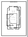
The F-TPBR Touchpad need only
be mounted and wired to the ex-
isting Freedom system. The
Freedom system can only support
two F-TP Touchpads or one F-TP
Touchpad and one F-TPBR
Touchpad.
POWER
The F-TPBR Touchpad is powered by the
keypad bus of the F-8 Panel. Each F-TPBR
Touchpad draws 55mA and an additional 20mA in
alarm. Deduct these values from the system
standby and alarm current, as described in the wir-
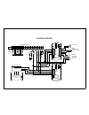
ing diagram.
NAPCO FREEDOM
F-TPBR TOUCHPAD
INSTALLATION INSTRUCTIONS
WI1450 10/05
This manual contains the Installation Instructions for the Freedom F-TPBR Touchpad. It is intended to be used in
conjunction with the Freedom F-8 Panel Installation Instructions (WI1431) and the Freedom F-8 Panel Program-
ming Instructions (WI1432).
© NAPCO 2005
R
333 Bayview Avenue
Amityville, New York 11701
For Sales and Repairs, (800) 645-9445
For Technical Service, (800) 645-9440
Publicly traded on NASDAQ Symbol: NSSC


