- DL manuals
- ABB
- Relays
- rec670
- Applications Manual
ABB rec670 Applications Manual
Summary of rec670
Page 1
Relion® 670 series — bay control rec670 version 2.2 iec application manual.
Page 3
Document id: 1mrk 511 401-uen issued: october 2017 revision: a product version: 2.2.1 © copyright 2017 abb. All rights reserved.
Page 4
Copyright this document and parts thereof must not be reproduced or copied without written permission from abb, and the contents thereof must not be imparted to a third party, nor used for any unauthorized purpose. The software and hardware described in this document is furnished under a license and...
Page 5
Disclaimer the data, examples and diagrams in this manual are included solely for the concept or product description and are not to be deemed as a statement of guaranteed properties. All persons responsible for applying the equipment addressed in this manual must satisfy themselves that each intende...
Page 6
Conformity this product complies with the directive of the council of the european communities on the approximation of the laws of the member states relating to electromagnetic compatibility (emc directive 2004/108/ec) and concerning electrical equipment for use within specified voltage limits (low-...
Page 7
Table of contents section 1 introduction.....................................................................19 this manual...................................................................................... 19 intended audience.........................................................................
Page 8
Example on how to connect a star connected three- phase ct set to the ied......................................................... 67 example how to connect delta connected three-phase ct set to the ied....................................................................72 example how to connect sing...
Page 9
Pmu report function blocks connection rules in pcm600 application configuration tool (act)....................112 setting guidelines...................................................................... 118 section 7 differential protection................................................... 123 high...
Page 10
2nd harmonic restrain...........................................................164 parallel transformer inrush current logic...............................165 switch onto fault logic...........................................................166 settings for each step (x = 1, 2, 3 and 4)...............
Page 11
Broken conductor check brcptoc ............................................. 214 identification.............................................................................. 214 application.................................................................................214 setting guidelines...........
Page 12
Two step residual overvoltage protection rov2ptov ................. 235 identification.............................................................................. 235 application.................................................................................235 setting guidelines....................
Page 13
Current and voltage selection for cvgapc function............254 base quantities for cvgapc function..................................257 application possibilities........................................................ 257 inadvertent generator energization...................................... 258...
Page 14
Identification.............................................................................. 283 application.................................................................................283 synchronizing.......................................................................283 synchrocheck..........
Page 15
Lock-out initiation................................................................. 311 evolving fault........................................................................ 312 automatic continuation of the auto reclosing sequence....... 313 thermal overload protection holding the auto recloser b...
Page 16
Configuration setting............................................................ 362 interlocking for bus-section disconnector a1a2_dc ................ 363 application............................................................................363 signals in single breaker arrangement..................
Page 17
Application.................................................................................429 setting guidelines...................................................................... 429 single command, 16 signals singlecmd.................................... 429 identification.......................
Page 18
Application.................................................................................447 fault current reversal logic................................................... 447 weak-end infeed logic..........................................................448 setting guidelines......................
Page 19
Boolean to integer conversion with logical node representation, 16 bit btigapc..................................................... 464 identification.............................................................................. 464 application...........................................................
Page 20
Application.................................................................................488 setting guidelines...................................................................... 491 setting procedure on the ied............................................... 491 event function event..............
Page 21
Application.................................................................................525 setting guidelines...................................................................... 525 function for energy calculation and demand handling etpmmtr 526 identification....................................
Page 22
Setting guidelines................................................................. 555 spa communication protocol......................................................... 555 application.................................................................................555 setting guidelines.............
Page 23
Application.................................................................................579 setting guidelines...................................................................... 580 rated system frequency primval................................................ 580 identification.................
Page 24
Rated equivalent secondary e.M.F. Requirements......................601 breaker failure protection..................................................... 601 non-directional instantaneous and definitive time, phase and residual overcurrent protection......................................602 non-direct...
Page 25
Section 1 introduction 1.1 this manual guid-ab423a30-13c2-46af-b7fe-a73bb425eb5f v18 the application manual contains application descriptions and setting guidelines sorted per function. The manual can be used to find out when and for what purpose a typical protection function can be used. The manual...
Page 26
1.3 product documentation 1.3.1 product documentation set guid-3aa69ea6-f1d8-47c6-a8e6-562f29c67172 v15 iec07000220-4-en.Vsd p la nn in g & p ur ch as e e ng in ee rin g in st al lin g c om m is si on in g o pe ra tio n m ai nt en an ce d ec om m is si on in g d ei ns ta lli ng & d is po sa l applic...
Page 27
Describes the process of testing an ied in a substation which is not in service. The chapters are organized in the chronological order in which the ied should be commissioned. The relevant procedures may be followed also during the service and maintenance activities. The operation manual contains in...
Page 28
1.3.3 related documents guid-94e8a5ca-be1b-45af-81e7-5a41d34ee112 v5 documents related to rec670 document numbers application manual 1mrk 511 401-uen commissioning manual 1mrk 511 403-uen product guide 1mrk 511 404-ben technical manual 1mrk 511 402-uen type test certificate 1mrk 511 404-ten 670 seri...
Page 29
The caution hot surface icon indicates important information or warning about the temperature of product surfaces. Class 1 laser product. Take adequate measures to protect the eyes and do not view directly with optical instruments. The caution icon indicates important information or warning related ...
Page 30
• the character ^ in front of an input/output signal name indicates that the signal name may be customized using the pcm600 software. • the character * after an input signal name indicates that the signal must be connected to another function block in the application configuration to achieve a valid...
Page 31
Function block name edition 1 logical nodes edition 2 logical nodes bfptrc_f01 bfptrc bfptrc bfptrc_f02 bfptrc bfptrc bfptrc_f03 bfptrc bfptrc bfptrc_f04 bfptrc bfptrc bfptrc_f05 bfptrc bfptrc bfptrc_f06 bfptrc bfptrc bfptrc_f07 bfptrc bfptrc bfptrc_f08 bfptrc bfptrc bfptrc_f09 bfptrc bfptrc bfptrc_...
Page 32
Function block name edition 1 logical nodes edition 2 logical nodes busptrc_b8 busptrc busptrc busptrc_b9 busptrc busptrc busptrc_b10 busptrc busptrc busptrc_b11 busptrc busptrc busptrc_b12 busptrc busptrc busptrc_b13 busptrc busptrc busptrc_b14 busptrc busptrc busptrc_b15 busptrc busptrc busptrc_b1...
Page 33
Function block name edition 1 logical nodes edition 2 logical nodes bzntpdif_a bzntpdif bzatgapc bzatpdif bzntgapc bzntpdif bzntpdif_b bzntpdif bzbtgapc bzbtpdif bzntgapc bzntpdif cbpgapc cbplln0 cbpmmxu cbpptrc holptov hph1ptov ph3ptuc ph3ptoc rp3pdop cbpmmxu cbpptrc holptov hph1ptov ph3ptoc ph3ptu...
Page 34
Function block name edition 1 logical nodes edition 2 logical nodes efpioc efpioc efpioc efrwpioc efrwpioc efrwpioc etpmmtr etpmmtr etpmmtr fdpspdis fdpspdis fdpspdis fmpspdis fmpspdis fmpspdis frpspdis fpsrpdis fpsrpdis ftaqfvr ftaqfvr ftaqfvr fufspvc sddrfuf fufspvc sddspvc genpdif genpdif gengapc...
Page 35
Function block name edition 1 logical nodes edition 2 logical nodes lczsptov lczsptov lczsptov ld0lln0 lln0 - ldlpsch ldlpdif ldlpsch ldrgfc stsggio ldrgfc lexpdis lexpdis lexpdis lexptrc lfpttr lfpttr lfpttr lmbrflo lmbrflo lmbrflo lolsptr lolsptr lolsptr lovptuv lovptuv lovptuv lphd lphd lpttr lpt...
Page 36
Function block name edition 1 logical nodes edition 2 logical nodes pslpsch zmrpsl pslpsch pspppam pspppam pspppam pspptrc qcbay qcbay bay/lln0 qcrsv qcrsv qcrsv rchlcch rchlcch rchlcch refpdif refpdif refpdif rotiphiz rotiphiz rotiphiz rotiptrc rov2ptov gen2lln0 ph1ptrc rov2ptov ph1ptrc rov2ptov sa...
Page 37
Function block name edition 1 logical nodes edition 2 logical nodes t2wpdif t2wpdif t2wgapc t2wpdif t2wphar t2wptrc t3wpdif t3wpdif t3wgapc t3wpdif t3wphar t3wptrc tclyltc tclyltc tclyltc tcsltc tcmyltc tcmyltc tcmyltc teigapc teiggio teigapc teiggio teilgapc teilggio teilgapc tmagapc tmaggio tmagap...
Page 38
Function block name edition 1 logical nodes edition 2 logical nodes zmcapdis zmcapdis zmcapdis zmcpdis zmcpdis zmcpdis zmfcpdis zmfclln0 psfpdis zmfpdis zmfptrc zmmmxu psfpdis zmfpdis zmfptrc zmmmxu zmfpdis zmflln0 psfpdis zmfpdis zmfptrc zmmmxu psfpdis psfpdis zmfpdis zmfptrc zmmmxu zmhpdis zmhpdis...
Page 39
Section 2 application 2.1 general ied application m13637-3 v13 the intelligent electronic device (ied) is used for the control, protection and monitoring of different types of bays in power networks. The ied is especially suitable for applications in control systems where the iec 61850–8–1 ed 1 or e...
Page 40
Disturbance recording and fault locator are available to allow independent post- fault analysis after primary disturbances in case of a failure in the protection system. Duplex communication channels for transfer of up to 192 intertrip and binary signals are available on each remote-end data communi...
Page 41
Iec 61850 or function name ansi function description bay control rec670 (customized) rec670 (a30) rec670 (b30) rec670 (c30) rec670 (d30) differential protection hzpdif 87 high impedance differential protection, single phase 0-6 3-a02 3-a02 6-a07 3-a02 2.3 back-up protection functions guid-a8d0852f-8...
Page 42
Iec 61850 or function name ansi function description bay control rec670 (customized) rec670 (a30) rec670 (b30) rec670 (c30) rec670 (d30) trpttr 49 thermal overload protection, two time constants 0-6 1-c51 1-c52 2-c53 1-c51 ccrbrf 50bf breaker failure protection 0-6 1-c51 2-c52 3-c53 1-c51 stbptoc 50...
Page 43
2.4 control and monitoring functions guid-e3777f16-0b76-4157-a3bf-0b6b978863de v15 iec 61850 or function name ansi function description bay control rec670 (customized) rec670 (a30) rec670 (b30) rec670 (c30) rec670 (d30) control sesrsyn 25 synchrocheck, energizing check and synchronizing 0-6 1 2 3 1 ...
Page 44
Iec 61850 or function name ansi function description bay control rec670 (customized) rec670 (a30) rec670 (b30) rec670 (c30) rec670 (d30) spc8gapc single point generic control function 8 signals 5 5 5 5 5 autobits automation bits, command function for dnp3.0 3 3 3 3 3 singlecmd single command, 16 sig...
Page 45
Iec 61850 or function name ansi function description bay control rec670 (customized) rec670 (a30) rec670 (b30) rec670 (c30) rec670 (d30) andqt, indcombspqt, indextspqt, invalidqt, inverterqt, orqt, pulsetimerqt, rsmemoryqt, srmemoryqt, timersetqt, xorqt configurable logic blocks q/t (see table 7 ) 0...
Page 46
Basic configurable logic block total number of instances srmemory 40 timerset 60 xor 40 table 4: number of function instances in apc10 function name function description total number of instances scilo interlocking 10 bb_es 3 a1a2_bs 2 a1a2_dc 3 abc_bc 1 bh_conn 1 bh_line_a 1 bh_line_b 1 db_bus_a 1 ...
Page 47
Table 5: number of function instances in apc15 function name function description total number of instances scilo interlocking 15 bb_es 3 a1a2_bs 2 a1a2_dc 3 abc_bc 1 bh_conn 1 bh_line_a 1 bh_line_b 1 db_bus_a 1 db_bus_b 1 db_line 1 abc_line 1 ab_trafo 1 scswi switch controller 15 sxswi circuit swit...
Page 48
Table 6: number of function instances in apc30 function name function description total number of instances scilo interlocking 30 bb_es 6 a1a2_bs 4 a1a2_dc 6 abc_bc 2 bh_conn 2 bh_line_a 2 bh_line_b 2 db_bus_a 3 db_bus_b 3 db_line 3 abc_line 6 ab_trafo 4 scswi switch controller 30 sxswi circuit swit...
Page 49
Table 8: total number of instances for extended logic package extended configurable logic block total number of instances and 180 gate 49 inv 180 lld 49 or 180 pulsetimer 89 rsmemory 40 slgapc 74 srmemory 130 timerset 109 vsgapc 120 xor 89 iec 61850 or function name ansi function description bay con...
Page 50
Iec 61850 or function name ansi function description bay control rec670 (customized) rec670 (a30) rec670 (b30) rec670 (c30) rec670 (d30) mvgapc generic communication function for measured values 24 24 24 24 24 binstatrep logical signal status report 3 3 3 3 3 range_xp measured value expander block 6...
Page 51
2.5 communication guid-5f144b53-b9a7-4173-80cf-cd4c84579cb5 v15 iec 61850 or function name ansi function description bay control rec670 (customized) rec670 (a30) rec670 (b30) rec670 (c30) rec670 (d30) station communication lonspa, spa spa communication protocol 1 1 1 1 1 ade lon communication protoc...
Page 52
Iec 61850 or function name ansi function description bay control rec670 (customized) rec670 (a30) rec670 (b30) rec670 (c30) rec670 (d30) goosevctrrcv horizontal communication via goose for vctr 7 7 7 7 7 goosevctrconf goose vctr configuration for send and receive 1 1 1 1 1 multicmdrcv, multicmdsnd m...
Page 53
Iec 61850 or function name ansi function description bay control rec670 (customized) rec670 (a30) rec670 (b30) rec670 (c30) rec670 (d30) schlcch access point diagnostic for non-redundant ethernet port 6 6 6 6 6 rchlcch access point diagnostic for redundant ethernet ports 3 3 3 3 3 dhcp dhcp configur...
Page 54
Table 9: number of function instances in synchrophasor report, 8 phasors function name function description number of instances pmuconf configuration parameters for c37.118 2011 and ieee1344 protocol 1 pmureport protocol reporting via ieee 1344 and c37.118 1 phasorreport1 protocol reporting of phaso...
Page 55
Iec 61850 or function name description authman authority management ftpaccs ftp access with password gbasval global base values for settings altms time master supervision altim time management comstatus protocol diagnostic table 11: local hmi functions iec 61850 or function name ansi description lhm...
Page 56
50
Page 57
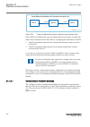
Section 3 configuration 3.1 description of configuration rec670 ip14799-1 v2 3.1.1 introduction ip14800-1 v1 3.1.1.1 description of configuration a30 m15200-3 v7 the configuration of the ied is shown in figure 2 . This configuration is used in single breaker arrangements with single or double busbar...
Page 58
Rec670 a30 – double busbar in single breaker arrangement 12ai (6i + 6u) qb1 qa1 qb2 qb9 s cilo 3 control s cswi 3 control s xswi 3 control s cilo 3 control s cswi 3 control s xswi 3 control s cilo 3 control s cswi 3 control s xswi 3 control s cilo 3 control s cswi 3 control s xswi 3 control drp rdre...
Page 59
Control, measuring and interlocking is fully configured, including communication with other bays such as other lines and the bus coupler over goose. The following should be noted. The configuration is made with the binary input and binary output boards in the basic ied delivery. In many cases this i...
Page 60
Rec670 b30 - double breaker arrangement 12ai (6i + 6u) qb1 qa1 qb61 qb2 qa2 qb62 qb9 s cilo 3 control s cswi 3 control s xcbr 3 control etp mmtr met w/varh brc ptoc 46 iub> cc psdc 52pd pd other functions available from the function library lov ptuv 27 3u vdc ptov 60 ud> ccs spvc 87 ind/i tcl yltc 8...
Page 61
This configuration is used in one-and-a-half breaker arrangements for a full diameter. The configuration can also be used for a section of the diameter with utilization of a part of the apparatuses only. Control, measuring and interlocking is fully configured, including communication with other bays...
Page 62
S cilo 3 control s cswi 3 control s xswi 3 control s cilo 3 control s cswi 3 control s xswi 3 control s cilo 3 control s cswi 3 control s xswi 3 control s cilo 3 control s cswi 3 control s xswi 3 control s cilo 3 control s cswi 3 control s xswi 3 control s cilo 3 control s cswi 3 control s xswi 3 co...
Page 63
3.1.1.4 description of configuration d30 guid-15d86a4c-4d37-432e-8dc2-518814830097 v1 rec670 d30 – double busbar in single breaker arrangement with pmu functionality 12ai (6i + 6u) qb1 qa1 qb2 qb9 s cilo 3 control s cswi 3 control s xswi 3 control s cilo 3 control s cswi 3 control s xswi 3 control s...
Page 64
Optional functions are available in pcm600 application configuration tool and can be configured by the user. Interface to analog and binary io:s are configurable without need of configuration changes. Analog and control circuits have been pre- defined. Other signals need to be applied as required fo...
Page 65
Section 4 analog inputs 4.1 introduction semod55003-5 v11 analog input channels must be configured and set properly in order to get correct measurement results and correct protection operations. For power measuring, all directional and differential functions, the directions of the input currents mus...
Page 66
4.2.1 setting of the phase reference channel semod55055-5 v3 all phase angles are calculated in relation to a defined reference. An appropriate analog input channel is selected and used as phase reference. The parameter phaseangleref defines the analog channel that is used as phase angle reference. ...
Page 67
With correct setting of the primary ct direction, ctstarpoint set to fromobject or toobject, a positive quantities always flowing towards the protected object and a direction defined as forward always is looking towards the protected object. The following examples show the principle. 4.2.2.1 example...
Page 68
Transformer protection transformer line setting of current input: set parameter ctstarpoint with transformer as reference object. Correct setting is "toobject" forward reverse definition of direction for directional functions line protection setting of current input: set parameter ctstarpoint with t...
Page 69
Transformer and line protection transformer line setting of current input: set parameter ctstarpoint with transformer as reference object. Correct setting is "toobject" reverse forward definition of direction for directional line functions setting of current input: set parameter ctstarpoint with tra...
Page 70
Transformer and line protection transformer line setting of current input for transformer functions: set parameter ctstarpoint with transformer as reference object. Correct setting is "toobject" forward reverse definition of direction for directional line functions setting of current input for trans...
Page 71
Busbar protection busbar 1 2 2 1 en06000196.Vsd ied 1 iec06000196 v2 en-us figure 11: example how to set ctstarpoint parameters in the ied for busbar protection, it is possible to set the ctstarpoint parameters in two ways. The first solution will be to use busbar as a reference object. In that case...
Page 72
The main ct ratios must also be set. This is done by setting the two parameters ctsec and ctprim for each current channel. For a 1000/1 a ct, the following settings shall be used: • ctprim = 1000 (value in a) • ctsec =1 (value in a). 4.2.2.4 examples on how to connect, configure and set ct inputs fo...
Page 73
However, in some cases, the following rated secondary currents are used as well: • 2a • 10a the ied fully supports all of these rated secondary values. It is recommended to: • use 1a rated ct input into the ied in order to connect cts with 1a and 2a secondary rating • use 5a rated ct input into the ...
Page 74
L1 il 1 il 2 il 3 l2 l3 protected object ct 600/5 star connected il1 il2 il3 ied iec13000002-4-en.Vsdx 1 2 3 4 smai2 block revrot ^grp2l1 ^grp2l2 ^grp2l3 ^grp2n ai3p ai1 ai2 ai3 ai4 ain 5 in iec13000002 v4 en-us figure 13: star connected three-phase ct set with star point towards the protected objec...
Page 75
3) these three connections are the links between the three current inputs and the three input channels of the preprocessing function block 4). Depending on the type of functions, which need this current information, more than one preprocessing block might be connected in parallel to the same three p...
Page 76
L1 il 1 il 2 il 3 l2 l3 protected object ct 800/1 star connected il1 il2 il3 ied iec11000026-4-en.Vsdx 4 1 2 3 smai2 block revrot ^grp2l1 ^grp2l2 ^grp2l3 ^grp2n ai3p ai1 ai2 ai3 ai4 ain 5 in iec11000026 v4 en-us figure 14: star connected three-phase ct set with its star point away from the protected...
Page 77
L1 il 1 il 2 il 3 l2 l3 protected object ct 800/1 star connected il1 il2 il3 in ied 1 3 4 2 5 iec06000644-4-en.Vsdx 6 smai2 block revrot ^grp2l1 ^grp2l2 ^grp2l3 ^grp2n ai3p ai1 ai2 ai3 ai4 ain iec06000644 v4 en-us figure 15: star connected three-phase ct set with its star point away from the protect...
Page 78
5) is a connection made in the signal matrix tool (smt) and application configuration tool (act), which connects the residual/neutral current input to the fourth input channel of the preprocessing function block 6). Note that this connection in smt shall not be done if the residual/neutral current i...
Page 79
L1 il 1 il 2 il 3 l2 l3 protected object ied c t 600 /5 in d el ta d ab c on ne ct ed il1-il2 il2-il3 il3-il1 1 2 3 4 iec11000027-3-en.Vsdx smai2 block revrot ^grp2l1 ^grp2l2 ^grp2l3 ^grp2n ai3p ai1 ai2 ai3 ai4 ain iec11000027 v3 en-us figure 16: delta dab connected three-phase ct set 1mrk 511 401-u...
Page 80
Where: 1) shows how to connect three individual phase currents from a delta connected three-phase ct set to three ct inputs of the ied. 2) is the trm where these current inputs are located. It shall be noted that for all these current inputs the following setting values shall be entered. Ct prim =60...
Page 81
L1 il 1 il 2 il 3 l2 l3 protected object ied c t 800 /1 in d el ta d ac c on ne ct ed il3-il2 il2-il1 il1-il3 2 3 4 iec11000028-3-en.Vsdx smai2 block revrot ^grp2l1 ^grp2l2 ^grp2l3 ^grp2n ai3p ai1 ai2 ai3 ai4 ain 1 iec11000028 v3 en-us figure 17: delta dac connected three-phase ct set in this case, ...
Page 82
For correct terminal designations, see the connection diagrams valid for the delivered ied. Protected object l1 l2 l3 ied in p ins ins 2 iec11000029-4-en.Vsdx 4 3 c t 1000 /1 a) b) (+) (+) (-) (-) (+) (-) 1 smai2 block revrot ^grp2l1 ^grp2l2 ^grp2l3 ^grp2n ai3p ai1 ai2 ai3 ai4 ain iec11000029 v4 en-...
Page 83
4.2.3 relationships between setting parameter base current, ct rated primary current and minimum pickup of a protection ied guid-8eb19363-9178-4f04-a6ac-af0c2f99c5ab v1 note that for all line protection applications (e.G. Distance protection or line differential protection) the parameter base curren...
Page 84
132 110 3 3 kv v equation2016 v1 en-us (equation 1) the following setting should be used: vtprim=132 (value in kv) vtsec=110 (value in v) 4.2.4.2 examples how to connect, configure and set vt inputs for most commonly used vt connections semod55055-60 v6 figure 19 defines the marking of voltage trans...
Page 85
4.2.4.3 examples on how to connect a three phase-to-earth connected vt to the ied semod55055-87 v9 figure 20 gives an example on how to connect a three phase-to-earth connected vt to the ied. It gives an overview of required actions by the user in order to make this measurement available to the buil...
Page 86
L1 ied l2 132 2 110 2 kv v 1 3 2 132 2 110 2 kv v iec16000140-1-en.Vsdx 4 smai2 block ^grp2l1 ^grp2l2 ^grp2l1l2 ^grp2n ai2p ai1 ai2 ai3 ai4 ain 5 iec16000140 v1 en-us figure 21: a two phase-to-earth connected vt where: 1) shows how to connect three secondary phase-to-earth voltages to three vt input...
Page 87
3) are three connections made in signal matrix tool (smt), which connect these three voltage inputs to first three input channels of the preprocessing function block 5). Depending on the type of functions which need this voltage information, more then one preprocessing block might be connected in pa...
Page 88
L1 ied l2 l3 13.8 120 kv v 1 2 #not used 13.8 120 kv v . 5 iec06000600-5-en.Vsdx 4 smai2 block revrot ^grp2l1 ^grp2l2 ^grp2l3 ^grp2n ai3p ai1 ai2 ai3 ai4 ain 3 iec06000600 v5 en-us figure 22: a two phase-to-phase connected vt where: 1) shows how to connect the secondary side of a phase-to-phase vt t...
Page 89
3) are three connections made in the signal matrix tool (smt), application configuration tool (act), which connects these three voltage inputs to first three input channels of the preprocessing function block 5). Depending on the type of functions, which need this voltage information, more than one ...
Page 90
L1 ied l2 l3 6.6 3 110 3 kv v +3uo 6.6 3 110 3 kv v 6.6 3 110 3 kv v 1 2 4 3 # not used 5 iec06000601-4-en.Vsdx # not used # not used smai2 block revrot ^grp2l1 ^grp2l2 ^grp2l3 ^grp2n ai3p ai1 ai2 ai3 ai4 ain iec06000601 v4 en-us figure 23: open delta connected vt in high impedance earthed power sys...
Page 91
Where: 1) shows how to connect the secondary side of the open delta vt to one vt input on the ied. +3u0 shall be connected to the ied 2) is the trm where this voltage input is located. It shall be noted that for this voltage input the following setting values shall be entered: 3 6.6 11.43 vtprim kv ...
Page 92
4.2.4.6 example how to connect the open delta vt to the ied for low impedance earthed or solidly earthed power systems semod55055-199 v6 figure 24 gives an example about the connection of an open delta vt to the ied for low impedance earthed or solidly earthed power systems. It shall be noted that t...
Page 93
1 l1 ied l2 l3 138 3 115 3 kv v +3uo 138 3 115 3 kv v 138 3 115 3 kv v iec06000602-4-en.Vsdx # not used # not used # not used smai2 block revrot ^grp2l1 ^grp2l2 ^grp2l3 ^grp2n ai3p ai1 ai2 ai3 ai4 ain 2 3 4 5 iec06000602 v4 en-us figure 24: open delta connected vt in low impedance or solidly earthed...
Page 94
Where: 1) shows how to connect the secondary side of open delta vt to one vt input in the ied. +3uo shall be connected to the ied. 2) is trm where this voltage input is located. It shall be noted that for this voltage input the following setting values shall be entered: 138 3 138 3 vtprim kv = × = e...
Page 95
Section 5 local hmi amu0600442 v14 iec13000239-3-en.Vsd iec13000239 v3 en-us figure 25: local human-machine interface the lhmi of the ied contains the following elements: • keypad • display (lcd) • led indicators • communication port for pcm600 1mrk 511 401-uen a section 5 local hmi bay control rec6...
Page 96
The lhmi is used for setting, monitoring and controlling. 5.1 display guid-55739d4f-1da5-4112-b5c7-217aaf360ea5 v11 the lhmi includes a graphical monochrome liquid crystal display (lcd) with a resolution of 320 x 240 pixels. The character size can vary. The amount of characters and rows fitting the ...
Page 97
Feedback signal for the function button control action. The led is connected to the required signal with pcm600. Iec13000281-1-en.Vsd guid-c98d972d-d1d8-4734-b419-161dbc0dc97b v1 en-us figure 27: function button panel the indication led panel shows on request the alarm text labels for the indication...
Page 98
5.2 leds amu0600427 v13 the lhmi includes three status leds above the display: ready, start and trip. There are 15 programmable indication leds on the front of the lhmi. Each led can indicate three states with the colors: green, yellow and red. The texts related to each three-color led are divided i...
Page 99
Iec16000076-1-en.Vsd iec16000076 v1 en-us figure 29: openclose_led connected to sxcbr 5.3 keypad amu0600428 v17 the lhmi keypad contains push-buttons which are used to navigate in different views or menus. The push-buttons are also used to acknowledge alarms, reset indications, provide help and swit...
Page 100
1 18 19 7 6 5 4 3 2 8 20 21 22 17 16 15 14 13 12 11 10 9 23 24 iec15000157-2-en.Vsd iec15000157 v2 en-us figure 30: lhmi keypad with object control, navigation and command push- buttons and rj-45 communication port 1...5 function button 6 close 7 open 8 escape 9 left 10 down 11 up 12 right 13 key 14...
Page 101
20 clear 21 help 22 communication port 23 programmable indication leds 24 ied status leds 5.4 local hmi functionality 5.4.1 protection and alarm indication guid-09ccb9f1-9b27-4c12-b253-fbe95ea537f5 v15 protection indicators the protection indicator leds are ready, start and trip. The start and trip ...
Page 102
Table 14: trip led (red) led state description off normal operation. On a protection function has tripped. An indication message is displayed if the auto-indication feature is enabled in the local hmi. The trip indication is latching and must be reset via communication, lhmi or binary input on the l...
Page 103
5.4.3 front communication guid-fd72a445-c8c1-4bfe-90e3-0ac78ae17c45 v11 the rj-45 port in the lhmi enables front communication. • the green uplink led on the left is lit when the cable is successfully connected to the port. • the yellow led is not used; it is always off. Iec13000280-1-en.Vsd 1 2 gui...
Page 104
98.
Page 105
Section 6 wide area measurement system 6.1 c37.118 phasor measurement data streaming protocol configuration pmuconf guid-747c6ad7-e6a1-466e-92d1-68865681f92f v1 6.1.1 identification guid-1e140ea0-d198-443a-b445-47cefd2e6134 v1 function description iec 61850 identification iec 60617 identification an...
Page 106
Information is available in the sections short guidance for the use of tcp and short guidance for the use of udp . Pmureport: 1 pmureport: 2 pmu id: x pmu id: y tcp ip tcp port tcp client_1 tcp client_2 tcp client_3 tcp client_4 tcp client_5 tcp client_6 tcp client_7 tcp client_8 udp client group_1 ...
Page 107
All the frames (the header frame, configuration frame, command frame and data frame) are communicated over the same tcp port. The client can request (by sending a command frame) a configuration and/or header via the tcp channel and the requested configuration and/or header will be sent back to the c...
Page 108
5. Udpdestport[x] – udp destination port number for udp client group[x] 6. Tcpportudpdatactrl[x] – tcp port to control of data sent over udp client group[x], i.E. To receive commands and send configuration frames 7. Sendcfgonudp[x] – send configuration frame 2 (cfg-2) on udp for client group[x] it i...
Page 109
In case of multicast ip, it will be the network switches and routers that take care of replicating the packet to reach multiple receivers. Multicast mechanism uses network infrastructure efficiently by requiring the ied to send a packet only once, even if it needs to be delivered to a large number o...
Page 110
There are settings for phasor type (positive sequence, negative sequence or zero sequence in case of 3-phase phasor and l1, l2 or l3 in case of single phase phasor), pmu's service class (protection or measurement), phasor representation (polar or rectangular) and the data types for phasor data, anal...
Page 111
Iec140000119-2-en.Vsd iec140000119 v2 en-us figure 34: multiple instances of phasorreport blocks figure 35 shows both instances of analogreport function blocks. The instance number is visible in the bottom of each function block. For each instance, there are three separate analogreport blocks capabl...
Page 112
Iec140000121-2-en.Vsd iec140000121 v2 en-us figure 36: multiple instances of binaryreport blocks 6.2.3 operation principle guid-eb2b9096-2f9d-4264-b2d2-8d9dc65697e8 v3 the phasor measurement unit (pmu) features three main functional principles: • to measure the power system related ac quantities (vo...
Page 113
Figure 37 shows an overview of the pmu functionality and operation. In this figure, only one instance of pmureport (pmureport1) is shown. Note that connection of different signals to the pmureport, in this figure, is only an example and the actual connections and reported signals on the ieeec37.118/...
Page 114
Ied. This feature is essential for proper operation of the pmureport function or for protection during generator start-up and shut-down procedure. This adaptive filtering is ensured by proper configuration and settings of all relevant pre-processing blocks, see signal matrix for analog inputs in the...
Page 115
Pid-6244-monitoreddata v2 table 16: pmureport monitored data name type values (range) unit description timestat boolean 1=ready 0=fail - time synchronization status freq real - hz frequency freqgrad real - - rate of change of frequency freqrefchsel integer - - frequency reference channel number sele...
Page 116
F 0 is the nominal frequency f s is the reporting rate 6.2.3.3 scaling factors for analogreport channels guid-0ddaf6a9-8643-4fdd-97cf-9e35ef40af7e v2 the internal calculation of analog values in the ied is based on 32 bit floating point. Therefore, if the user selects to report the analog data (anal...
Page 117
Example 1: 3277.0 analogxrange = iecequation2446 v1 en-us the scale factor is calculated as follows: (3277.0 2.0) 0.1 and 0.0 65535.0 scalefactor offset ´ = = = iecequation2447 v1 en-us the scale factor will be sent as 1 on configuration frame 2, and 0.1 on configuration frame 3. The range of analog...
Page 118
6.2.3.4 pmu report function blocks connection rules in pcm600 application configuration tool (act) guid-66667179-f3e1-455b-8b99-6d73f37e949b v3 there are 3 important general rules which have to be considered in pcm600 act for the connection of preprocessor blocks (smai) and 3phsum blocks to phasorre...
Page 119
Rule 2: the same smai or 3phsum block can be connected to more than one phasorreport block only if all the connected phasorreport blocks have similar instance number or only if all the connected phasorreport blocks have similar settings for svcclass and reportrate. Figure 40 shows the settings for p...
Page 120
Iec140000127-2-en.Vsd iec140000127 v2 en-us figure 41: an example of correct connection of smai and phasorreport blocks in act figure 42 shows an example of wrong connection of smai and phasorreport blocks in act where the same smai block is connected to different phasorreport blocks with different ...
Page 121
Iec140000128-2-en.Vsd iec140000128 v2 en-us figure 42: an example of wrong connection of smai and phasorreport blocks in act rule 3: this rule is only related to the connection of 3phsum block to the phasorreport block. If 3phsum block is configured to use external dft reference (from smai reference...
Page 122
Iec140000129-2-en.Vsd iec140000129 v2 en-us figure 43: an example of correct connection of 3phsum and phasorreport blocks in act iec140000130-1-en.Vsd iec140000130 v1 en-us figure 44: smai1 setting parameters example-showing that smai3 is selected as the dft reference (dftrefgrp3) section 6 1mrk 511...
Page 123
Iec140000131-1-en iec140000131 v1 en-us figure 45: 3phsum setting parameters example-showing that 3phsum is using the external dft reference coming indirectly from smai3 figure 46 shows an example of wrong connection of 3phsum and phasorreport blocks in act where smai3 is configured as the reference...
Page 124
Different filtering applied to the 3phsum block, both smai reference block and 3phsum shall be connected to the same phasorreport instance. In this example (figure 46 ), smai3 adapts its filtering according to phasorreport1 instance 2 (due to connection) and 3phsum is adapting its filtering accordin...
Page 125
Each category has its corresponding parameter settings except for binaryreport function block which does not have any specific parameters and settings. 1. Pmureport is the main function block which controls the operation of other pmu reporting function blocks. Each instance of pmureport function blo...
Page 126
Synchrophasor data are sent via the phasors field of data frame organization of ieee c37.118.2 message format. Depends on the phasor data type, the size of phasors field can be 4 (integer) or 8 (float) bytes per ieee c37.118.2 message. Integer data type for the phasors corresponds to a 16-bit intege...
Page 127
+327.67 hz per second. Integer data type for rocof data represents 16- bit signed integers, range –32 767 to +32 767 32, and float data type represents actual value in ieee floating-point format. • sendfreqinfo: enables/disables sending of the frequency-deviation and rate of change of frequency (roc...
Page 128
• phasorxreport: enables/disables the phasor channel x (reporting of phasorx) by choosing on/off setting. • phasorx: the group selector for phasorx. Here, the user can select the type of reported synchrophasor from the phasor channel x as either a 3- phase symmetrical component or a single-phase pha...
Page 129
Section 7 differential protection 7.1 high impedance differential protection, single phase hzpdif ip14239-1 v4 7.1.1 identification m14813-1 v4 function description iec 61850 identification iec 60617 identification ansi/ieee c37.2 device number high impedance differential protection, single phase hz...
Page 130
3·id 3·id id 3·id 3·id g 3·id iec05000163-4-en.Vsd iec05000163 v4 en-us section 7 1mrk 511 401-uen a differential protection 124 bay control rec670 2.2 iec application manual.
Page 131
3·id z 3·id z iec05000738-3-en.Vsd iec05000738 v3 en-us figure 47: different applications of a 1ph high impedance differential protection hzpdif function 7.1.2.1 the basics of the high impedance principle semod54734-153 v9 the high impedance differential protection principle has been used for many y...
Page 132
Id iec05000164-2-en.Vsd r metrosil iec05000164 v3 en-us figure 48: example for the high impedance restricted earth fault protection application for a through fault one current transformer might saturate when the other cts still will feed current. For such a case a voltage will be developed across th...
Page 133
The minimum operating voltage has to be calculated (all loops) and the ied function is set higher than the highest achieved value (setting u>trip). As the loop resistance is the value to the connection point from each ct, it is advisable to do all the ct core summations in the switchgear to have sho...
Page 134
Table 17: 1 a channels: input with minimum operating down to 40 ma operating voltage u>trip stabilizing resistor r ohms operating current level 1 a stabilizing resistor r ohms operating current level 1 a 20 v 500 0.040 a -- -- 40 v 1000 0.040 a -- -- 60 v 1500 0.040 a 600 0.100 a 80 v 2000 0.040 a 8...
Page 135
It should be remembered that the vectorial sum of the currents must be used (ieds, metrosil and resistor currents are resistive). The current measurement is insensitive to dc component in fault current to allow the use of only the ac components of the fault current in the above calculations. The vol...
Page 136
I> r rres rl rct rct rl ur a) through load situation b) through fault situation ur ur c) internal faults ur protected object iec05000427-2-en.Vsd iec05000427 v2 en-us figure 49: the high impedance principle for one phase with two current transformer inputs section 7 1mrk 511 401-uen a differential p...
Page 137
7.1.3 connection examples for high impedance differential protection guid-8c58a73d-7c2e-4be5-ab87-b4c93fb7d62b v5 warning! Use extreme caution! Dangerously high voltages might be present on this equipment, especially on the plate with resistors. De-energize the primary object protected with this equ...
Page 138
2 three-phase plate with setting resistors and metrosils. Protective earth is a separate 4 mm screw terminal on the plate. 3 necessary connection for three-phase metrosil set. 4 position of optional test switch for secondary injection into the high impedance differential ied. 5 necessary connection ...
Page 139
Pos description 1 scheme earthing point ensure that only one earthing point exists in this scheme. 2 one-phase plate with stabilizing resistor and metrosil. Protective earth is a separate 4 mm screw terminal on the plate. 3 necessary connection for the metrosil. 4 position of optional test switch fo...
Page 140
For 5 a circuits say bigger than 100 ohms (2500 va). This ensures that the current will circulate and not go through the differential circuit at through faults. That the settings of u>alarm, u>trip and seriesresistor must be chosen such that both u>alarm/seriesresistor and u>trip/ seriesresistor are...
Page 141
3·id iec05000165-2-en.Vsd iec05000165 v2 en-us 3·id iec05000739-2-en.Vsd iec05000739 v2 en-us figure 52: the protection scheme utilizing the high impedance function for the t-feeder 1mrk 511 401-uen a section 7 differential protection bay control rec670 2.2 iec 135 application manual.
Page 142
Normally this scheme is set to achieve a sensitivity of around 20 percent of the used ct primary rating so that a low ohmic value can be used for the series resistor. It is strongly recommended to use the highest tap of the ct whenever high impedance protection is used. This helps in utilizing maxim...
Page 143
Ip approx a = ° + ° + × − ° ( ) × ≤ − 2000 1 100 0 20 0 3 10 60 10 275 3 equation1209 v2 en-us (equation 17) where 100 ma is the current drawn by the ied circuit and 10 ma is the current drawn by each ct just at pickup 20 ma is current drawn by metrosil at pickup the magnetizing current is taken fro...
Page 144
3·id iec05000176-3-en.Vsd iec05000176 v3 en-us figure 53: application of the1ph high impedance differential protection hzpdif function on a reactor setting example it is strongly recommended to use the highest tap of the ct whenever high impedance protection is used. This helps in utilizing maximum ...
Page 145
Basic data: current transformer ratio: 100/5 a (note: must be the same at all locations) ct class: 10 va 5p20 secondary resistance: 0.26 ohms cable loop resistance: 2 (one way) gives 1 ˣ 0.4 ohm at 75° c note! Only one way as the tertiary power system earthing is limiting the earth-fault current. If...
Page 146
7.1.4.5 alarm level operation m16850-196 v6 the 1ph high impedance differential protection hzpdif function has a separate alarm level, which can be used to give alarm for problems with an involved current transformer circuit. The setting level is normally selected to be around 10% of the operating v...
Page 147
Section 8 current protection 8.1 instantaneous phase overcurrent protection phpioc ip14506-1 v6 8.1.1 identification m14880-1 v5 function description iec 61850 identification iec 60617 identification ansi/ieee c37.2 device number instantaneous phase overcurrent protection phpioc 3i>> symbol-z v1 en-...
Page 148
8.1.3 setting guidelines ip14979-1 v1 m12915-4 v9 the parameters for instantaneous phase overcurrent protection phpioc are set via the local hmi or pcm600. This protection function must operate only in a selective way. So check all system and transient conditions that could cause its unwanted operat...
Page 149
Should be done using the minimum source impedance values for z a and the maximum source impedance values for z b in order to get the maximum through fault current from a to b. ~ ~ z a z b z l a b ied i fb fault iec09000022-1-en.Vsd iec09000022 v1 en-us figure 55: through fault current from a to b: i...
Page 150
The minimum primary setting (is) for the instantaneous phase overcurrent protection is then: min 1.3 s i i ³ × equation79 v3 en-us (equation 22) the protection function can be used for the specific application only if this setting value is equal to or less than the maximum fault current that the ied...
Page 151
Iec09000025-1-en.Vsd ~ ~ z a z b z l1 a b i m fault ied z l2 m c line 1 line 2 iec09000025 v1 en-us figure 58: two parallel lines. Influence from parallel line to the through fault current: i m the minimum theoretical current setting for the overcurrent protection function (imin) will be: imin max i...
Page 152
8.2 directional phase overcurrent protection, four steps oc4ptoc semod129998-1 v8 8.2.1 identification m14885-1 v6 function description iec 61850 identification iec 60617 identification ansi/ieee c37.2 device number directional phase overcurrent protection, four steps oc4ptoc toc-reva v2 en-us 51_67...
Page 153
Protections, they should have the same time delay characteristic. Therefore, a wide range of standardized inverse time characteristics are available for iec and ansi. It is also possible to tailor make the inverse time characteristic. Normally, it is required that the phase overcurrent protection sh...
Page 154
Common base ied values for primary current (ibase), primary voltage (ubase) and primary power (sbase) are set in the global base values for settings function gbasval. Globalbasesel: this is used to select gbasval function for reference of base values. Meastype: selection of discrete fourier filtered...
Page 155
U ref i dir iec09000636_2_vsd 1 2 2 3 4 iec09000636 v2 en-us figure 59: directional function characteristic 1. Rca = relay characteristic angle 2. Roa = relay operating angle 3. Reverse 4. Forward 8.2.3.1 settings for each step m12982-19 v10 x means step 1, 2, 3 and 4. Dirmodex: the directional mode...
Page 156
Table 19: inverse time characteristics curve name ansi extremely inverse ansi very inverse ansi normal inverse ansi moderately inverse ansi/ieee definite time ansi long time extremely inverse ansi long time very inverse ansi long time inverse iec normal inverse iec very inverse iec inverse iec extre...
Page 157
Txmin: minimum operate time for all inverse time characteristics. At high currents the inverse time characteristic might give a very short operation time. By setting this parameter the operation time of the step can never be shorter than the setting. Setting range: 0.000 - 60.000s in steps of 0.001s...
Page 158
For ansi inverse time characteristics, all three types of reset time characteristics are available: instantaneous (1), iec (2 = set constant time reset) and ansi (3 = current dependent reset time). For iec inverse time characteristics, the possible delay time settings are instantaneous (1) and iec (...
Page 159
Operate current current (a) the ied does not reset line phase current time (s) reset current iec05000203-en-2.Vsd iec05000203 v4 en-us figure 61: operate and reset current for an overcurrent protection the lowest setting value can be written according to equation 28 . Im ax ipu 1.2 k ³ × equation126...
Page 160
The protection must be calculated. Taking this value as a base, the highest pickup current setting can be written according to equation 29 . Ipu 0.7 isc min £ × equation1263 v2 en-us (equation 29) where: 0.7 is a safety factor iscmin is the smallest fault current to be detected by the overcurrent pr...
Page 161
Selectivity is assured if the time difference between the curves is larger than a critical time difference. Time-current curves fault current 10 10 0.01 10000 en05000204.Ai str tfunc1 n n tfunc2 trip time n iec05000204 v2 en-us figure 62: fault time with maintained selectivity the operation time can...
Page 162
Example for time coordination assume two substations a and b directly connected to each other via one line, as shown in the figure 63 . Consider a fault located at another line from the station b. The fault current to the overcurrent protection of ied b1 has a magnitude so that the overcurrent prote...
Page 163
40 100 40 40 220 t ms ms ms ms ms d ³ + + + = equation1266 v1 en-us (equation 32) where it is considered that: the operate time of overcurrent protection b1 is 40 ms the breaker open time is 100 ms the resetting time of protection a1 is 40 ms and the additional margin is 40 ms 8.3 instantaneous resi...
Page 164
Globalbasesel: this is used to select gbasval function for reference of base values. The basic requirement is to assure selectivity, that is efpioc shall not be allowed to operate for faults at other objects than the protected object (line). For a normal line in a meshed system single phase-to-earth...
Page 165
A safety margin of 5% for the maximum static inaccuracy and a safety margin of 5% for maximum possible transient overreach have to be introduced. An additional 20% is suggested due to inaccuracy of instrument transformers under transient conditions and inaccuracy in the system data. The minimum prim...
Page 166
( ) 100 s in i ibase iecequation17003 v1 en-us (equation 37) transformer inrush current shall be considered. The setting of the protection is set as a percentage of the base current (ibase). Operation: set the protection to on or off. In>>: set operate current in % of ib. In>>max and in>>min should ...
Page 167
• earth-fault protection of feeders in effectively earthed distribution and subtransmission systems. Normally these feeders have radial structure. • back-up earth-fault protection of transmission lines. • sensitive earth-fault protection of transmission lines. Ef4ptoc can have better sensitivity to ...
Page 168
Curve name ansi long time inverse iec normal inverse iec very inverse iec inverse iec extremely inverse iec short time inverse iec long time inverse iec definite time user programmable asea ri rxidg or rd (logarithmic) it is also possible to tailor make the inverse time characteristic. Normally it i...
Page 169
The parameters for the four step residual overcurrent protection are set via the local hmi or pcm600. The following settings can be done for the function. Common base ied values for primary current (ibase), primary voltage (ubase) and primary power (sbase) are set in the global base values for setti...
Page 170
Polmethod: defines if the directional polarization is from • voltage (3u 0 or u 2 ) • current (3i 0 · znpol or 3i 2 ·znpol where znpol is rnpol + jxnpol), or • both currents and voltage, dual (dual polarizing, (3u 0 + 3i 0 · znpol) or (u 2 + i 2 · znpol)). Normally voltage polarizing from the intern...
Page 171
Harmonic component. This component can be used to create a restrain signal to prevent this unwanted function. At current transformer saturation a false residual current can be measured by the protection. Here the 2 nd harmonic restrain can prevent unwanted operation as well. 2ndharmstab: the rate of...
Page 172
Usestartvalue: gives which current level should be used for the activation of the blocking signal. This is given as one of the settings of the steps: step 1/2/3/4. Normally, the step having the lowest operation current level should be set. 8.4.3.4 switch onto fault logic m15282-106 v4 in case of ene...
Page 173
8.4.3.5 settings for each step (x = 1, 2, 3 and 4) m15282-9 v12 operation: sets the protection to on or off. Dirmodex: the directional mode of step x. Possible settings are off/non- directional/forward/reverse. Characteristx: selection of time characteristic for step x. Definite time delay and diffe...
Page 174
Txmin: minimum operating time for inverse time characteristics. At high currents, the inverse time characteristic might give a very short operation time. By setting this parameter, the operation time of the step can never be shorter than the setting. Iminx operate time current tx txmin iec10000058 i...
Page 175
[ ] = + × - > æ ö ç ÷ ç ÷ ç ÷ æ ö ç ÷ ç ÷ è ø è ø p a t s b k i c in equation1189 v1 en-us (equation 38) further description can be found in the technical reference manual. Tprcrvx, ttrcrvx, tcrcrvx: parameters for user programmable of inverse reset time characteristic curve. Further description can...
Page 176
The different steps can be described as follows. Step 1 m15282-123 v6 this step has directional instantaneous function. The requirement is that overreaching of the protected line is not allowed. Iec05000150-3-en.Vsd in 3i 0 one- or two-phase earth-fault or unsymmetric short circuit without earth con...
Page 177
Iec05000151-en-2.Vsd in > one- or two-phase-earth-fault 3i 0 iec05000151 v2 en-us figure 72: step 1, second calculation. Remote busbar with, one line taken out of service the requirement is now according to equation 40 . Step1 0 i 1.2 3i (remote busbar with one line out) ³ × equation1200 v3 en-us (e...
Page 178
Step1 0 i 1.2 3i ³ × equation1201 v3 en-us (equation 41) the current setting for step 1 is chosen as the largest of the above calculated residual currents, measured by the protection. Step 2 m15282-144 v7 this step has directional function and a short time delay, often about 0.4 s. Step 2 shall secu...
Page 179
In > one phase-to-earth fault 3i 0 in > 3i 01 iec05000155-en-2.Vsd iec05000155 v3 en-us figure 75: step 2, selectivity calculation a second criterion for step 2 is according to equation 43 . 1 1 0 step2 step1 0 3i i .2 i 3i ³ × × equation1203 v4 en-us (equation 43) where: i step1 is the current sett...
Page 180
Step 4 m15282-177 v4 this step normally has non-directional function and a relatively long time delay. The task for step 4 is to detect and initiate trip for earth faults with large fault resistance, for example tree faults. Step 4 shall also detect series faults where one or two poles, of a breaker...
Page 181
• earth-fault and phase-phase short circuit protection of feeders in effectively earthed distribution and subtransmission systems. Normally these feeders have radial structure. • back-up earth-fault and phase-phase short circuit protection of transmission lines. • sensitive earth-fault protection of...
Page 182
Curve name ansi long time very inverse ansi long time inverse iec normal inverse iec very inverse iec inverse iec extremely inverse iec short time inverse iec long time inverse iec definite time user programmable asea ri rxidg (logarithmic) there is also a user programmable inverse time characterist...
Page 183
Is required, it is important to set the definite time delay for that stage to zero. 8.5.3.1 settings for each step guid-cfb327ef-c5c4-44b5-ab4b-9c2916355fc5 v5 x means step 1, 2, 3 and 4. Dirmodeselx: the directional mode of step x. Possible settings are off/ nondirectional/forward/reverse. Characte...
Page 184
Tx: definite time delay for step x. The definite time tx is added to the inverse time when inverse time characteristic is selected. Note that the value set is the time between activation of the start and the trip outputs. Kx: time multiplier for the dependent (inverse) characteristic. Iminx: minimum...
Page 185
For the independent time delay characteristics the possible delay time settings are instantaneous (1) and iec (2 = set constant time reset). For ansi inverse time delay characteristics all three types of reset time characteristics are available; instantaneous (1), iec (2 = set constant time reset) a...
Page 186
Anglerca forward area iop = i2 upol=-u2 reverse area iec10000031-1-en.Vsd iec10000031 v1 en-us figure 78: relay characteristic angle given in degree in a transmission network a normal value of rca is about 80°. Upolmin: minimum polarization (reference) voltage % of ubase. I>dir: operate residual cur...
Page 187
8.6.1 identification semod172025-2 v4 function description iec 61850 identification iec 60617 identification ansi/ieee c37.2 device number sensitive directional residual over current and power protection sdepsde - 67n 8.6.2 application semod171959-4 v12 in networks with high impedance earthing, the ...
Page 188
• sensitive directional residual overcurrent protection gives possibility for better sensitivity. The setting possibilities of this function are down to 0.25 % of ibase, 1 a or 5 a. This sensitivity is in most cases sufficient in high impedance network applications, if the measuring ct ratio is not ...
Page 189
In a high impedance system the fault current is assumed to be limited by the system zero sequence shunt impedance to earth and the fault resistance only. All the series impedances in the system are assumed to be zero. In the setting of earth fault protection, in a high impedance earthed system, the ...
Page 190
C n 0 c n jx 3r z jx 3r - × = - + equation1946 v1 en-us (equation 49) where r n is the resistance of the neutral point resistor in many systems there is also a neutral point reactor (petersen coil) connected to one or more transformer neutral points. In such a system the impedance z 0 can be calcula...
Page 191
Substation a substation b z lineab,1 (pos. Seq) z lineab,0 (zero seq) z linebc,1 (pos. Seq) z linebc,0 (zero seq) u 0a u 0b 3i 0 phase to earth fault r n z t,1 (pos. Seq) z t,0 (zero seq) source impedance z sc (pos. Seq) en06000654.Vsd iec06000654 v1 en-us figure 80: equivalent of power system for c...
Page 192
The residual power, measured by the sensitive earth fault protections in a and b will be: 0 a 0 a 0 s 3u 3i = × equation1951 v1 en-us (equation 54) 0 b 0 b 0 s 3u 3i = × equation1952 v1 en-us (equation 55) the residual power is a complex quantity. The protection will have a maximum sensitivity in th...
Page 193
With opmode set to 3i0cosfi the current component in the direction equal to the characteristic anglercadir has the maximum sensitivity. The characteristic for rcadir is equal to 0° is shown in figure 81 . = = o o 0 , 90 rcadir roadir 0 3i j = - 0 ref ang(3i ) ang(3u ) - = 0 ref 3u u 0 3i cos × j iec...
Page 194
The characteristic for this opmode when rcadir = 0° and roadir = 80° is shown in figure 83 . -3u 0 operate area 3i 0 rcadir = 0º roadir = 80º iec06000652-3-en.Vsd iec06000652 v3 en-us figure 83: characteristic for rcadir = 0° and roadir = 80° dirmode is set forward or reverse to set the direction of...
Page 195
Faulted feeder only. Rcadir is set equal to -90° in an isolated network as all currents are mainly capacitive. Roadir is relay operating angle. Roadir is identifying a window around the reference direction in order to detect directionality. Roadir is set in degrees. For angles differing more than ro...
Page 196
Table 24: inverse time characteristics curve name ansi extremely inverse ansi very inverse ansi normal inverse ansi moderately inverse ansi/ieee definite time ansi long time extremely inverse ansi long time very inverse ansi long time inverse iec normal inverse iec very inverse iec inverse iec extre...
Page 197
8.7 thermal overload protection, one time constant, celsius/fahrenheit lcpttr/lfpttr ip14512-1 v7 8.7.1 identification 8.8 thermal overload protection, two time constants trpttr ip14513-1 v4 8.8.1 identification m14877-1 v2 function description iec 61850 identification iec 60617 identification ansi/...
Page 198
• oa: the air is naturally circulated to the coolers without fans and the oil is naturally circulated without pumps. • foa: the coolers have fans to force air for cooling and pumps to force the circulation of the transformer oil. The protection can have two sets of parameters, one for non-forced coo...
Page 199
Transformer an ambient temperature of 20°c is used. For lower ambient temperatures the load ability is increased and vice versa. Irefmult can be set within a range: 0.01 - 10.00. Ibase1: base current for setting given as percentage of ibase. This setting shall be related to the status with no coolin...
Page 200
Tau1low: multiplication factor to adjust the time constant tau1 if the current is lower than the set value ilowtau1. Ilowtau1 is set in % of ibase1. Tau2high: multiplication factor to adjust the time constant tau2 if the current is higher than the set value ihightau2. Ihightau2 is set in % of ibase2...
Page 201
8.9.1 identification m14878-1 v5 function description iec 61850 identification iec 60617 identification ansi/ieee c37.2 device number breaker failure protection, 3-phase activation and output ccrbrf 3i>bf symbol-u v1 en-us 50bf 8.9.2 application m13916-3 v7 in the design of the fault clearance syste...
Page 202
Small. This can be the case for some generator protection application (for example reverse power protection) or in case of line ends with weak end infeed. Retripmode: this setting states how the re-trip function shall operate. Retrip off means that the re-trip function is not activated. Cb pos check...
Page 203
Functionmode is set current/contact breaker failure for high current faults are safely detected by the current measurement function. To increase security the contact based function should be disabled for high currents. The setting can be given within the range 5 – 200% of ibase. In>: residual curren...
Page 204
Time the fault occurs protection operate time trip and start ccrbrf normal t cbopen margin retrip delay t1 t cbopen after re-trip t bfpreset minimum back-up trip delay t2 critical fault clearance time for stability iec05000479_2_en.Vsd iec05000479 v2 en-us figure 84: time sequence t2mph: time delay ...
Page 205
8.10 stub protection stbptoc ip14515-1 v3 8.10.1 identification m17108-1 v2 function description iec 61850 identification iec 60617 identification ansi/ieee c37.2 device number stub protection stbptoc 3i>stub symbol-t v1 en-us 50stb 8.10.2 application m12904-3 v5 in a 1½-breaker switchyard the line ...
Page 206
Iec05000465 v2 en-us figure 85: typical connection for stbptoc in 1½-breaker arrangement. 8.10.3 setting guidelines m12909-3 v5 the parameters for stub protection stbptoc are set via the local hmi or pcm600. The following settings can be done for the stub protection. Globalbasesel: selects the globa...
Page 207
I>: current level for the stub protection, set in % of ibase. This parameter should be set so that all faults on the stub can be detected. The setting should thus be based on fault calculations. T: time delay of the operation. Normally the function shall be instantaneous. 8.11 pole discordance prote...
Page 208
8.11.3 setting guidelines m13274-3 v8 the parameters for the pole discordance protection ccpdsc are set via the local hmi or pcm600. The following settings can be done for the pole discordance protection. Globalbasesel: selects the global base value group used by the function to define ibase, ubase ...
Page 209
8.12.2 application semod151283-4 v5 the task of a generator in a power plant is to convert mechanical energy available as a torque on a rotating shaft to electric energy. Sometimes, the mechanical power from a prime mover may decrease so much that it does not cover bearing losses and ventilation los...
Page 210
Design the reverse power protection so that it can detect reverse power independent of the flow of power to the power plant auxiliaries. Hydro turbines tolerate reverse power much better than steam turbines do. Only kaplan turbine and bulb turbines may suffer from reverse power. There is a risk that...
Page 211
8.12.3 setting guidelines semod172134-4 v7 globalbasesel: selects the global base value group used by the function to define ibase, ubase and sbase as applicable. Operation: with the parameter operation the function can be set on/off. Mode: the voltage and current used for the power measurement. The...
Page 212
Operate angle1(2) power1(2) p q en06000441.Vsd iec06000441 v1 en-us figure 87: underpower mode the setting power1(2) gives the power component pick up value in the angle1(2) direction. The setting is given in p.U. Of the generator rated power, see equation 73 . Minimum recommended setting is 0.2% of...
Page 213
Operate angle1(2) = 0 ° power1(2) p q en06000556.Vsd iec06000556 v1 en-us figure 88: for low forward power the set angle should be 0° in the underpower function tripdelay1(2) is set in seconds to give the time delay for trip of the stage after pick up. Hysteresis1(2) is given in p.U. Of generator ra...
Page 214
The value of k=0.92 is recommended in generator applications as the trip delay is normally quite long. The calibration factors for current and voltage measurement errors are set % of rated current/voltage: iampcomp5, iampcomp30, iampcomp100 uampcomp5, uampcomp30, uampcomp100 iangcomp5, iangcomp30, i...
Page 215
Steam turbines easily become overheated if the steam flow becomes too low or if the steam ceases to flow through the turbine. Therefore, turbo-generators should have reverse power protection. There are several contingencies that may cause reverse power: break of a main steam pipe, damage to one or m...
Page 216
Diesel engines should have reverse power protection. The generator will take about 15% of its rated power or more from the system. A stiff engine may require perhaps 25% of the rated power to motor it. An engine that is well run in might need no more than 5%. It is necessary to obtain information fr...
Page 217
Table 27: complex power calculation set value mode formula used for complex power calculation l1, l2, l3 * * * 1 1 2 2 3 3 l l l l l l s u i u i u i = × + × + × equation1697 v1 en-us (equation 77) arone * * 1 2 1 2 3 3 l l l l l l s u i u i = × - × equation1698 v1 en-us (equation 78) posseq * 3 poss...
Page 218
Operate angle1(2) power1(2) p q en06000440.Vsd iec06000440 v1 en-us figure 90: overpower mode the setting power1(2) gives the power component pick up value in the angle1(2) direction. The setting is given in p.U. Of the generator rated power, see equation 86 . Minimum recommended setting is 0.2% of ...
Page 219
Operate angle1(2 ) = 180 o power1(2) p q iec06000557-2-en.Vsd iec06000557 v2 en-us figure 91: for reverse power the set angle should be 180° in the overpower function tripdelay1(2) is set in seconds to give the time delay for trip of the stage after pick up. Hysteresis1(2) is given in p.U. Of genera...
Page 220
The value of k=0.92 is recommended in generator applications as the trip delay is normally quite long. The calibration factors for current and voltage measurement errors are set % of rated current/voltage: iampcomp5, iampcomp30, iampcomp100 uampcomp5, uampcomp30, uampcomp100 iangcomp5, iangcomp30, i...
Page 221
Set the unsymmetrical current, which is relation between the difference of the minimum and maximum phase currents to the maximum phase current to typical iub> = 50%. Note that it must be set to avoid problem with asymmetry under minimum operating conditions. Set the time delay toper = 5 - 60 seconds...
Page 222
Capacitor unit (can) rack iec09000753_1_en.Vsd iec09000753 v1 en-us figure 92: replacement of a faulty capacitor unit within scb there are four types of the capacitor unit fusing designs which are used for construction of scbs: externally fused where an individual fuse, externally mounted, protects ...
Page 223
Because the scbs are built from the individual capacitor units the overall connections may vary. Typically used scb configurations are: 1. Delta-connected banks (generally used only at distribution voltages) 2. Single wye-connected banks 3. Double wye-connected banks 4. H-configuration, where each p...
Page 224
1. Capacitor units should be capable of continuous operation including harmonics, but excluding transients, to 110% of rated ied root-mean-square (rms) voltage and a crest voltage not exceeding of rated rms voltage. The capacitor should also be able to carry 135% of nominal current. The voltage capa...
Page 225
Cbpgapc function can be used to provide the last four types of protection mentioned in the above list. 8.15.3 setting guidelines guid-cecd6525-779c-4a77-844d-031aaee3a5b6 v1 guid-7c456976-ba0d-4aac-9c7a-f73af52b2b44 v2 this setting example will be done for application as shown in figure 93 : preproc...
Page 226
General settings: operation =on; to enable the function ibase =289a; fundamental frequency scb rated current in primary amperes. This value is used as a base value for pickup settings of all other features integrated in this function. Reconnection inhibit feature: operationrecin =on; to enable this ...
Page 227
Holdtu> =200% (of scb voltage rating); voltage level required for pickup tholdt =10s; definite time delay for harmonic overload trip settings for idmt delay step holidmtu> =110% (of scb voltage rating); voltage level required for pickup of idmt stage. Selected value gives pickup recommended by inter...
Page 228
8.16.2 application guid-622cdddd-6d03-430e-a82d-861a4cbe067c v7 a breakdown of the insulation between phase conductors or a phase conductor and earth results in a short-circuit or an earth fault. Such faults can result in large fault currents and may cause severe damage to the power system primary e...
Page 229
Ubase shall be entered as rated phase-to-phase voltage of the protected object in primary kv. 8.16.2.2 application possibilities guid-5053f964-c2d6-4611-b5ef-ac3db0889f51 v5 vrpvoc function can be used in one of the following applications: • voltage controlled over-current • voltage restrained over-...
Page 230
8.16.3 setting guidelines guid-2ae85ec4-669e-47c0-add4-3dba83581096 v2 8.16.3.1 explanation of the setting parameters guid-9b777e6d-602b-4214-9170-a44ed2d725bf v3 operation: set to on in order to activate the function; set to off to switch off the complete function. Startcurr: operation phase curren...
Page 231
Uhighlimit: when the measured phase-to-phase voltage is higher than uhighlimit/100*ubase, than the start level of the overcurrent stage is startcurr/ 100*ibase. In particular, in slope mode it define the second point of the characteristic (startcurr/100*ibase ; uhighlimit/100*ubase). 8.16.3.2 voltag...
Page 232
• start current of the overcurrent stage: 150% of generator rated current at rated generator voltage; • start voltage of the undervoltage stage: 70% of generator rated voltage; • trip time: 3.0 s. The overcurrent stage and the undervoltage stage shall be set in the following way: 1. Set operation to...
Page 233
Section 9 voltage protection 9.1 two step undervoltage protection uv2ptuv ip14544-1 v3 9.1.1 identification m16876-1 v7 function description iec 61850 identification iec 60617 identification ansi/ieee c37.2 device number two step undervoltage protection uv2ptuv 3u symbol-r-2u-greater-than v2 en-us 2...
Page 234
In many cases, uv2ptuv is a useful function in circuits for local or remote automation processes in the power system. 9.1.3 setting guidelines m13851-3 v9 all the voltage conditions in the system where uv2ptuv performs its functions should be considered. The same also applies to the associated equip...
Page 235
9.1.3.6 settings for two step undervoltage protection m13851-65 v14 the following settings can be done for two step undervoltage protection uv2ptuv: conntype: sets whether the measurement shall be phase-to-earth fundamental value, phase-to-phase fundamental value, phase-to-earth rms value or phase-t...
Page 236
Resettypecrvn: this parameter for inverse time characteristic can be set to instantaneous, frozen time, linearly decreased. The default setting is instantaneous. Tiresetn: reset time for step n if inverse time delay is used, given in s. The default value is 25 ms. Kn: time multiplier for inverse tim...
Page 237
9.2.2 application m13799-3 v9 two step overvoltage protection ov2ptov is applicable in all situations, where reliable detection of high voltage is necessary. Ov2ptov is used for supervision and detection of abnormal conditions, which, in combination with other protection functions, increase the secu...
Page 238
Which is normally set to the nominal voltage level (phase-to-phase) of the power system or the high voltage equipment under consideration. The time delay for the ov2ptov can sometimes be critical and related to the size of the overvoltage - a power system or a high voltage component can withstand sm...
Page 239
Operation: off/on. Ubase (given in globalbasesel): base voltage phase to phase in primary kv. This voltage is used as reference for voltage setting. Ov2ptov measures selectively phase-to-earth voltages, or phase-to-phase voltage chosen by the setting conntype. The function will operate if the voltag...
Page 240
Tresetn: reset time for step n if definite time delay is used, given in s. The default value is 25 ms. Tnmin: minimum operation time for inverse time characteristic for step n, given in s. For very high voltages the overvoltage function, using inverse time characteristic, can give very short operati...
Page 241
9.3 two step residual overvoltage protection rov2ptov ip14546-1 v4 9.3.1 identification semod54295-2 v6 function description iec 61850 identification iec 60617 identification ansi/ieee c37.2 device number two step residual overvoltage protection rov2ptov 2(u0>) iec15000108 v1 en-us 59n 9.3.2 applica...
Page 242
Situations, where the residual overvoltage protection is used to protect some specific equipment, the time delay is shorter. Some applications and related setting guidelines for the residual voltage level are given below. 9.3.3.1 equipment protection, such as for motors, generators, reactors and tra...
Page 243
3u 0 ul 1 iec07000190-2-en.Vsd iec07000190 v2 en-us figure 95: earth fault in non-effectively earthed systems 9.3.3.5 direct earthed system guid-ea622f55-7978-4d1c-9af7-2bab5628070a v8 in direct earthed systems, an earth fault on one phase is indicated by voltage collapse in that phase. The other he...
Page 244
9.3.3.6 settings for two step residual overvoltage protection m13853-21 v13 operation: off or on ubase (given in globalbasesel) is used as voltage reference for the set pickup values. The voltage can be fed to the ied in different ways: 1. The ied is fed from a normal voltage transformer group where...
Page 245
Example, in the case of the protection of a transformer that might be overexcited. The time delay must be co-ordinated with other automated actions in the system. Tresetn: reset time for step n if definite time delay is used, given in s. The default value is 25 ms. Tnmin: minimum operation time for ...
Page 246
9.4 voltage differential protection vdcptov semod153860-1 v2 9.4.1 identification semod167723-2 v2 function description iec 61850 identification iec 60617 identification ansi/ieee c37.2 device number voltage differential protection vdcptov - 60 9.4.2 application semod153893-5 v3 the voltage differen...
Page 247
Ud>l1 ph l2 ph l3 u1 u2 ud>l1 ph l2 ph l3 u1 u2 ph l3 ph l2 single earthed wye double wye iec06000390_1_en.Vsd iec06000390 v3 en-us figure 97: connection of voltage differential protection vdcptov function to detect unbalance in capacitor banks (one phase only is shown) vdcptov function has a block ...
Page 248
Ud> u1 u2 to protection to excitation gen en06000389.Vsd iec06000389 v1 en-us figure 98: supervision of fuses on generator circuit voltage transformers 9.4.3 setting guidelines semod153915-5 v3 the parameters for the voltage differential function are set via the local hmi or pcm600. The following se...
Page 249
Udtrip: the voltage differential level required for tripping is set with this parameter. For application on capacitor banks the setting will depend of the capacitor bank voltage and the number of elements per phase in series and parallel. Capacitor banks must be tripped before excessive voltage occu...
Page 250
9.5.2 application semod171876-4 v3 the trip of the circuit breaker at a prolonged loss of voltage at all the three phases is normally used in automatic restoration systems to facilitate the system restoration after a major blackout. Loss of voltage check (lovptuv) generates a trip signal only if the...
Page 251
Section 10 frequency protection 10.1 underfrequency protection saptuf ip15746-1 v3 10.1.1 identification m14865-1 v5 function description iec 61850 identification iec 60617 identification ansi/ieee c37.2 device number underfrequency protection saptuf f symbol-p v1 en-us 81 10.1.2 application m13350-...
Page 252
There are two specific application areas for saptuf: 1. To protect equipment against damage due to low frequency, such as generators, transformers, and motors. Overexcitation is also related to low frequency 2. To protect a power system, or a part of a power system, against breakdown, by shedding lo...
Page 253
10.2.2 application m14952-3 v4 overfrequency protection function saptof is applicable in all situations, where reliable detection of high fundamental power system frequency is needed. The power system frequency, and rate of change of frequency, is a measure of the unbalance between the actual genera...
Page 254
10.3 rate-of-change of frequency protection sapfrc ip15748-1 v4 10.3.1 identification m14868-1 v4 function description iec 61850 identification iec 60617 identification ansi/ieee c37.2 device number rate-of-change of frequency protection sapfrc df/dt > symbol-n v1 en-us 81 10.3.2 application m14966-...
Page 255
Between load and generation. In such situations load or generation shedding has to take place very quickly, and there might not be enough time to wait until the frequency signal has reached an abnormal value. Actions are therefore taken at a frequency level closer to the primary nominal level, if th...
Page 256
Operating frequency is nearly equal to 1, mechanical stress on the blades is approximately 300 times the nonresonant operating condition stress values. The stress magnification factor is shown in the typical resonance curve in figure 99 . 1.0 - + frequency or resonant frequency ratio s tr e ss m ag ...
Page 257
56 0.01 0.1 1 10 100 1000 58 frequency (hz) time (minutes) time (minutes) time (minutes) time (minutes) iec13000258-1-en.Ai continuous operation prohibited operation 60 62 56 0.01 0.1 1 10 100 1000 58 frequency (hz) continuous operation 60 62 56 0.01 0.1 1 10 100 1000 58 frequency (hz) 60 62 continu...
Page 258
Setting procedure on the ied the parameters for the frequency time accumulation protection ftaqfvr are set using the local hmi or through the dedicated software tool in protection and control manager (pcm600). Common base ied values for primary current ibase and primary voltage ubase are set in the ...
Page 259
Section 11 multipurpose protection 11.1 general current and voltage protection cvgapc ip14552-1 v2 11.1.1 identification m14886-2 v3 function description iec 61850 identification iec 60617 identification ansi/ieee c37.2 device number general current and voltage protection cvgapc 2(i>/u - 11.1.2 appl...
Page 260
• definite time delay or inverse time overcurrent toc/idmt delay for both steps • second harmonic supervision is available in order to only allow operation of the overcurrent stage(s) if the content of the second harmonic in the measured current is lower than pre-set level • directional supervision ...
Page 261
Table 28: available selection for current quantity within cvgapc function set value for parameter "currentinput” comment 1 phase1 cvgapc function will measure the phase l1 current phasor 2 phase2 cvgapc function will measure the phase l2 current phasor 3 phase3 cvgapc function will measure the phase...
Page 262
Set value for parameter "voltageinput" comment 4 posseq cvgapc function will measure internally calculated positive sequence voltage phasor 5 -negseq cvgapc function will measure internally calculated negative sequence voltage phasor. This voltage phasor will be intentionally rotated for 180° in ord...
Page 263
11.1.2.2 base quantities for cvgapc function semod53443-112 v3 the parameter settings for the base quantities, which represent the base (100%) for pickup levels of all measuring stages shall be entered as setting parameters for every cvgapc function. Base current shall be entered as: 1. Rated phase ...
Page 264
• rotor overload protection • loss of excitation protection (directional pos. Seq. Oc protection) • reverse power/low forward power protection (directional pos. Seq. Oc protection, 2% sensitivity) • dead-machine/inadvertent-energizing protection • breaker head flashover protection • improper synchro...
Page 265
Function will, with a delay for example 10 s, detect the situation when the generator is not connected to the grid (standstill) and activate the overcurrent function. The overvoltage function will detect the situation when the generator is taken into operation and will disable the overcurrent functi...
Page 266
1. Connect three-phase power line currents and three-phase power line voltages to one cvgapc instance (for example, gf04) 2. Set currentinput to negseq (please note that cvgapc function measures i2 current and not 3i2 current; this is essential for proper oc pickup level setting) 3. Set voltageinput...
Page 267
• the set values for rcadir and roadir settings will be as well applicable for oc2 stage • setting dirmode_oc2 shall be set to reverse • setting parameter startcurr_oc2 shall be made more sensitive than pickup value of forward oc1 element (that is, typically 60% of oc1 set pickup level) in order to ...
Page 268
Equation 96 can be re-written in the following way without changing the value for the operate time of the negative sequence inverse overcurrent ied: 2 2 1 op ns r k x t i x i × = æ ö ç ÷ × è ø equation1374 v1 en-us (equation 98) in order to achieve such protection functionality with one cvgapc funct...
Page 269
1. Select negative sequence current as measuring quantity for this cvgapc function 2. Make sure that the base current value for the cvgapc function is equal to the generator rated current 3. Set k_oc1 = 20 4. Set a_oc1= 1/0.07 2 = 204.0816 5. Set b_oc1 = 0.0, c_oc1 = 0.0 and p_oc1 = 2.0 6. Set start...
Page 270
By defining parameter x equal to the per unit value for the desired pickup for the overload ied in accordance with the following formula: x = 116% = 1.16 pu equation1377 v2 en-us (equation 101) formula 3.5can be re-written in the following way without changing the value for the operate time of the g...
Page 271
1. Set k equal to the iec or ansi standard generator capability value 2. Set parameter a_oc1 equal to the value 1/x2 3. Set parameter c_oc1 equal to the value 1/x2 4. Set parameters b_oc1 = 0.0 and p_oc1=2.0 5. Set startcurr_oc1 equal to the value x then the oc1 step of the cvgapc function can be us...
Page 272
6. Set base current value to the rated current of the protected object in primary amperes 7. Enable one overcurrent step (for example, oc1) 8. Select parameter curvetype_oc1 to value iec def. Time 9. Set parameter startcurr_oc1 to value 5% 10. Set parameter tdef_oc1 to desired time delay (for exampl...
Page 273
12. Set vdepfact_oc1 to value 0.25 13. Set uhighlimit_oc1 to value 100% 14. Set ulowlimit_oc1 to value 25% proper operation of the cvgapc function made in this way can easily be verified by secondary injection. All other settings can be left at the default values. Furthermore the other built-in prot...
Page 274
Furthermore the other build-in protection elements can be used for other protection and alarming purposes. 0.2 0.4 0.6 -0.2 0.6 0.8 0.8 1 d ilowset b a c 0.4 0.2 0 1.2 1.4 -0.4 -0.6 -0.8 -rca operating region q [pu] p [pu] rca u ps i ps ilowset operating region en05000535.Vsd iec05000535 v2 en-us fi...
Page 275
Section 12 system protection and control 12.1 multipurpose filter smaihpac guid-6b541154-d56b-452f-b143-4c2a1b2d3a1f v1 12.1.1 identification guid-8224b870-3daa-44bf-b790-6600f2ad7c5d v1 function description iec 61850 identification iec 60617 identification ansi/ieee c37.2 device number multipurpose...
Page 276
• overcurrent or overvoltage protection at specific frequency harmonic, sub- harmonic, inter-harmonic etc. • presence of special railway frequencies (e.G. 16.7hz or 25hz) in the three- phase power system • sensitive reverse power protection • stator or rotor earth fault protection for special inject...
Page 277
Where: • t op is the operating time of the relay • t 01 is fixed time delay (setting) • k is a constant (setting) • i s is measured subsynchronous current in primary amperes the existing relay was applied on a large 50hz turbo generator which had shaft mechanical resonance frequency at 18.5hz. The r...
Page 278
[ ] p t a s b k i c in æ ö ç ÷ ç ÷ = + × ç ÷ æ ö - ç ÷ ç ÷ > è ø è ø equation13000031 v1 en-us (equation 106) in order to adapt to the previous relay characteristic the above equation can be re- written in the following way: [ ] 01 1 1 0 so s so t k i s t i i æ ö ç ÷ ç ÷ = + × ç ÷ æ ö ç ÷ - ç ÷ ç ÷ ...
Page 279
Rcadir -75 roadir 75 lowvolt_vm 0.5 oc1 setting group1 operation_oc1 on startcurr_oc1 30.0 currmult_oc1 2.0 curvetype_oc1 programmable tdef_oc1 0.00 k_oc1 1.00 tmin1 30 tmin_oc1 1.40 rescrvtype_oc1 instantaneous tresetdef_oc1 0.00 p_oc1 1.000 a_oc1 118.55 b_oc1 0.640 c_oc1 0.000 1mrk 511 401-uen a s...
Page 280
274.
Page 281
Section 13 secondary system supervision 13.1 current circuit supervision ccsspvc ip14555-1 v5 13.1.1 identification m14870-1 v5 function description iec 61850 identification iec 60617 identification ansi/ieee c37.2 device number current circuit supervision ccsspvc - 87 13.1.2 application m12395-13 v...
Page 282
Current circuit supervision ccsspvc compares the residual current from a three- phase set of current transformer cores with the neutral point current on a separate input taken from another set of cores on the same current transformer. Iminop: it must be set as a minimum to twice the residual current...
Page 283
First case influences the operation of all voltage-dependent functions while the second one does not affect the impedance measuring functions. The negative sequence detection algorithm, based on the negative-sequence measuring quantities is recommended for use in isolated or high-impedance earthed n...
Page 284
Fuse fail when closing the local breaker when the line is already energized from the other end. When the remote breaker closes the voltage will return except in the phase that has a persistent fuse fail. Since the local breaker is open there is no current and the dead phase indication will persist i...
Page 285
100 2 2 3 ibase i i equation1520 v5 en-us (equation 109) where: i2 is the maximal negative sequence current during normal operating conditions, plus a margin of 10...20% ibase is the base current for the function according to the setting globalbasesel 13.2.3.4 zero sequence based m13683-43 v8 the ie...
Page 286
The setting of du> should be set high (approximately 60% of ubase) and the current threshold di low (approximately 10% of ibase) to avoid unwanted operation due to normal switching conditions in the network. The delta current and delta voltage function shall always be used together with either the n...
Page 287
13.3.2 application guid-ad63bf6c-0351-4e48-9fb2-9ab5cf0c521e v2 some protection functions operate on the basis of measured voltage at the relay point. Examples of such protection functions are distance protection function, undervoltage function and energisation-check function. These functions might ...
Page 288
13.3.3 setting guidelines guid-0d5a517c-1f92-46b9-ac2d-f41ed4e7c39e v1 guid-52bf4e8e-0b0c-4f75-99c4-0bcb22cdd166 v2 the parameters for fuse failure supervision vdspvc are set via the local hmi or pcm600. Guid-0b298162-c939-47e4-a89b-7e6bd7bebb2c v2 the voltage input type (phase-to-phase or phase-to-...
Page 289
Section 14 control 14.1 synchrocheck, energizing check, and synchronizing sesrsyn ip14558-1 v4 14.1.1 identification m14889-1 v4 function description iec 61850 identification iec 60617 identification ansi/ieee c37.2 device number synchrocheck, energizing check, and synchronizing sesrsyn sc/vc symbol...
Page 290
The bus and line frequencies must also be within a range of ±5 hz from the rated frequency. When the synchronizing option is included also for autoreclose there is no reason to have different frequency setting for the manual and automatic reclosing and the frequency difference values for synchronism...
Page 291
14.1.2.2 synchrocheck m12309-6 v10 the main purpose of the synchrocheck function is to provide control over the closing of circuit breakers in power networks in order to prevent closing if conditions for synchronism are not detected. It is also used to prevent the re- connection of two systems, whic...
Page 292
With a long operation time and high sensitivity regarding the frequency difference. The phase angle difference setting can be set for steady state conditions. Another example is the operation of a power network that is disturbed by a fault event: after the fault clearance a highspeed auto-reclosing ...
Page 293
Between cb a and cb b is energized (dllb) from substation 1 via the circuit breaker a and energization of station 2 is done by cb b energization check device for that breaker dbll. (or both). 1 2 a energizingcheck uhighbusenerg > 50 - 120 % of gblbaseselbus uhighlineenerg > 50 - 120 % of gblbasesell...
Page 294
Selected depends on the status of the breakers and/or disconnectors. By checking the status of the disconnectors auxiliary contacts, the right voltages for the synchronizing, synchrocheck and energizing check functions can be selected. Available voltage selection types are for single circuit breaker...
Page 295
Iec07000118 v3 en-us figure 107: selection of the energizing direction from a local hmi symbol through a selector switch function block. 14.1.3 application examples m12323-3 v7 the synchronizing function block can also be used in some switchyard arrangements, but with different parameter settings. B...
Page 296
14.1.3.1 single circuit breaker with single busbar m12324-3 v12 wa1_mcb line wa1 qb1 qa1 iec10000093-4-en.Vsd line_vt line_mcb wa1_mcb sesrsyn u3pbb1* u3pbb2* u3pln1* u3pln2* grp_off ub1ok ub1ff uln1ok uln1ff wa1_vt wa1_vt line_vt line_mcb wa1_mcb iec10000093 v4 en-us figure 108: connection of sesrs...
Page 297
14.1.3.2 single circuit breaker with double busbar, external voltage selection m12325-3 v8 wa1 wa2 qb1 qb2 line qa1 iec10000094-4-en.Vsd wa2_mcb wa1_mcb line_vt line_mcb sesrsyn u3pbb1* u3pbb2* u3pln1* u3pln2* grp_off ub1ok ub1ff uln1ok uln1ff wa1_vt/ wa2_vt line_vt line_mcb wa1_mcb/ wa2_mcb wa1_mcb...
Page 298
When internal voltage selection is needed, the voltage transformer circuit connections are made according to figure 110 . The voltage from the busbar 1 vt is connected to u3pbb1 and the voltage from busbar 2 is connected to u3pbb2. The voltage from the line vt is connected to u3pln1. The positions o...
Page 299
Connected to u3pln2 on all three function blocks. The positions of the disconnectors and vt fuses shall be connected as shown in figure 112 . 1mrk 511 401-uen a section 14 control bay control rec670 2.2 iec 293 application manual.
Page 300
Line1 qb2 qb1 qb61 qb62 wa1 wa2 iec10000097-4-en.Vsd setting parameter cbconfig = 1 ½ bus cb setting parameter cbconfig = tie cb setting parameter cbconfig = 1 ½ bus alt. Cb wa2_qa1 tie_qa1 line1_qb9 wa1_qa1 wa1_vt wa2_vt line1_vt line2_vt tie_qa1 wa2_qa1 line1_qb9 line2_qb9 wa1_mcb wa2_mcb line1_mc...
Page 301
The connections are similar in all sesrsyn functions, apart from the breaker position indications. The physical analog connections of voltages and the connection to the ied and sesrsyn function blocks must be carefully checked in pcm600. In all sesrsyn functions the connections and configurations mu...
Page 302
If only two sesrsyn functions are provided in the same ied, the connections and settings are according to the sesrsyn functions for wa1_qa1 and tie_qa1. 14.1.4 setting guidelines m12550-3 v14 the setting parameters for the synchronizing, synchrocheck and energizing check function sesrsyn are set via...
Page 303
• no voltage selection, no voltage sel. • single circuit breaker with double bus, double bus • 1 1/2 circuit breaker arrangement with the breaker connected to busbar 1, 1 1/2 bus cb • 1 1/2 circuit breaker arrangement with the breaker connected to busbar 2, 1 1/2 bus alt. Cb • 1 1/2 circuit breaker ...
Page 304
Will close at exactly the right instance if the networks run with a frequency difference. To avoid overlapping of the synchronizing function and the synchrocheck function the setting freqdiffmin must be set to a higher value than used setting freqdiffm, respective freqdiffa used for synchrocheck. Fr...
Page 305
Tminsynch the setting tminsynch is set to limit the minimum time at which the synchronizing closing attempt is given. The synchronizing function will not give a closing command within this time, from when the synchronizing is started, even if a synchronizing condition is fulfilled. A typical setting...
Page 306
Temporary interference. Should the conditions not persist for the specified time, the delay timer is reset and the procedure is restarted when the conditions are fulfilled again. Circuit breaker closing is thus not permitted until the synchrocheck situation has remained constant throughout the set d...
Page 307
The setting conditions may be such that the setting of the non-energized threshold value is higher than that of the energized threshold value. The parameters must therefore be set carefully to avoid overlapping. Umaxenerg this setting is used to block the closing when the voltage on the live side is...
Page 308
“dead time” differ then, the line will be energized until the breakers at both ends have opened. Open closed operate time line protection circuit breaker break time t ri p c o m m a n d c o n ta ct s s e p a ra te d a rc e x tin g u is h e rs fault duration circuit breaker open time fault duration r...
Page 309
Coordinate the residual current protections (earth fault protection) with the single- phase tripping and the auto reclosing function. Attention shall also be paid to "pole discordance" that arises when circuit breakers are provided with single-phase operating devices. These breakers need pole discor...
Page 310
Indicating faults outside the own line are typically connected to inhibit the auto recloser. Automatic reclosing should not be attempted when closing a cb and energizing a line onto a fault (sotf), except when multiple-shots are used where shots 2 etc. Will be started at sotf. Likewise a cb in a mul...
Page 311
• number of auto reclosing shots • auto reclosing program • auto reclosing dead times for each shot 14.2.2.1 auto reclosing operation off and on m12391-91 v6 operation of the automatic recloser can be set to off and on by a setting parameter or by external control. The setting parameter operation = ...
Page 312
14.2.2.3 start auto reclosing from circuit breaker open information m12391-100 v6 if a user wants to initiate auto reclosing from the circuit breaker open position instead of from protection trip signals, the function offers such a possibility. This starting mode is selected with the setting paramet...
Page 313
Extension delay is not possible to add to the three-phase high-speed auto reclosing dead time, t1 3phhs. 14.2.2.6 long trip signal m12391-117 v4 in normal circumstances the auto recloser is started with a protection trip command which resets quickly due to fault clearing. The user can set a maximum ...
Page 314
Disagreement and earth-fault protection trip during the single-phase dead time interval.. • if tr2p input is high and tr3p input is low (i.E. Two-phase trip): the timer for two-phase auto reclosing dead time is started and the 2pt1 output (two-phase reclosing in progress) is activated. • if tr3p inp...
Page 315
More shots are attempted. The expression “1*3ph” should be understood as “only one shot at three-phase auto reclosing”. 14.2.2.13 armode = 1ph + 1*2/3ph, 1-phase, 2-phase or 3-phase reclosing in the first shot m12391-146 v5 at single-phase or two-phase tripping, the operation is as in the above desc...
Page 316
Armode=1/2/3ph, is done from a hardware function key at the front of the ied, but alternatively there can for example, be a physical selector switch on the front of the panel which is connected to a binary to integer function block (btigapc). The connection example for selection of the auto reclosin...
Page 317
Shot can no longer be started. Depending on the set number of auto reclosing shots further shots may be made or the auto reclosing sequence is ended. After reclaim timer time-out the auto recloser resets, but the circuit breaker remains open. The circuit breaker closed information through the cbclos...
Page 318
Lock-out rxmd1 11 12 21 main zak close close command smbo or smbrrec or ccrbrf bu-trip zcvpsof-trip inhibit unsuccl trbu iec05000315-4-en.Vsd iec05000315-wmf v4 en-us figure 115: lock-out arranged with an external lock-out relay close command or smbrrec or ccrbrf bu-trip zcvpsof-trip inhibi t unsucc...
Page 319
(smpptrc) in the ied has an evolving fault timer which ensures that the second fault is always tripped three-phase. For other types of relays where the relays do not include this function, the prep3ph output (or the inverted permit1ph output) is used to prepare the other sub-system for three-phase t...
Page 320
Cbclosed and cbready these binary inputs should pick-up information from the circuit breaker. At three operating gears in the circuit breaker (single pole operated circuit breakers) the connection should be “all poles closed” (series connection of the no contacts) or “at least one pole open” (parall...
Page 321
Rstcount there is a counter for each type of auto reclosing and one for the total number of circuit breaker close commands issued. All counters are reset with the rstcount input or by an iec 61850 command. Skiphs the high-speed auto reclosing sequence can be skipped and be replaced by normal auto re...
Page 322
Needs to be connected only if the trip function block has been selected to give 1ph/2ph/3ph trip and an auto reclosing cycle with two phase reclosing is foreseen. Trsotf this is the signal “trip by switch onto fault”. It is usually connected to the “switch onto fault” output of line protection if mu...
Page 323
Active indicates that the auto recloser is active, from start until end of reclaim time. Blocked indicates that auto recloser is temporarily or permanently blocked. Closecb connect to a binary output for circuit breaker closing command. Count1p, count2p, count3p1, count3p2, count3p3, count3p4 and co...
Page 324
Seton indicates that auto recloser is switched on and operative. Succl if the circuit breaker closing command is given and the circuit breaker is closed within the set time interval tunsuccl, the succl output is activated after the set time interval tsuccessful. Syncfail the syncfail output indicate...
Page 325
On off blkon blkoff inhibit blocked seton inprogr active unsuccl succl closecb cbready cbclosed plclost 1pt1 wfmaster reset start tholhold ready trsotf sync input xx xx xx xx xx xx xx xx xx xx or output xx xx xx xx xx xx xx xx xx xx protection xxxx-trip zcvpsof-trip sesrsyn-autook bim bom smbrrec =i...
Page 326
On off blkon blkoff inhibit blocked seton inprogr active unsuccl succl closecb permit1p cbready cbclosed plclost 3pt1 wfmaster reset start 1pt1 2pt1 trsotf tr2p tr3p sync input xx xx xx xx xx xx xx xx xx xx or output xx or protection xxxx-trip zcvpsof-trip trip-tr2p trip-tr3p sesrsyn-autook ef4ptoc-...
Page 327
Should take the duration of the breaker closing time of the master into consideration before sending the breaker closing command. A setting twaitformaster sets a maximum wait time for the wait input to reset. If the wait time expires, the reclosing cycle of the slave is inhibited. If auto reclosing ...
Page 328
Iec04000137-4-en.Vsd active unsuccl ready closecb 3pt2 3pt3 wait cbclosed cbready trsotf start reset blkoff blkon off on blocked seton inprogr 3pt4 sync inhibit terminal ‘‘ master ” priority = high smbrrec closecb wait terminal ‘‘ slave ” priority = low cb1 cb2 wfmaster wfmaster *) other input/outpu...
Page 329
14.2.3.2 auto recloser settings guid-74980a07-cf89-488f-ab17-e5351d0032ee v1 the settings for the auto recloser are set using the local hmi (lhmi) or pcm600. This setting guideline describes the settings of the auto recloser using the lhmi. The settings for the auto recloser are found under main men...
Page 330
This facility will not influence the auto reclosing. A typical setting of tlongstartinh could be close to the auto reclosing dead time. Tinhibit: to ensure reliable interruption and temporary blocking of the auto recloser a resetting time delay tinhibit is used. The auto recloser will be blocked thi...
Page 331
Cutpulse: in circuit breakers without anti-pumping relays, the setting cutpulse = on can be used to avoid repeated closing operation when reclosing onto a fault. A new start will then cut the ongoing pulse. Tpulse: the circuit breaker closing command should be long enough to ensure reliable operatio...
Page 332
Other phenomena, for example wind, a greater number of auto reclosing attempts (shots) can be motivated. T1 1ph, t1 2ph, t1 3ph: there are separate settings for the first shot for single-, two- and three-phase auto reclosing dead times. Single-phase auto reclosing dead time: a typical setting is t1 ...
Page 333
Tslavedeadtime: when activating the wait input, in the auto recloser set as slave, every dead timer is changed to the value of setting tslavedeadtime and holds back the auto reclosing operation. When the wait input is reset at the time of a successful reclosing of the first circuit breaker, the slav...
Page 334
Station hmi gw cc station bus breakers disconnectors earthing switches iec08000227.Vsd apparatus control ied i/o local hmi apparatus control ied i/o apparatus control ied i/o local hmi local hmi iec08000227 v1 en-us figure 120: overview of the apparatus control functions features in the apparatus co...
Page 335
• reservation input resin • local remote locrem • local remote control locremctrl the signal flow between the function blocks is shown in figure 121 . To realize the reservation function, the function blocks reservation input (resin) and bay reserve (qcrsv) also are included in the apparatus control...
Page 336
Merging unit bay level ied xcbr xcbr xcbr scswi iec 61850 on station bus xswi qcbay scilo scswi goosexlnrcv scilo xlnproxy goosexlnrcv xlnproxy -qa1 -qb1 -qb9 goose over process bus iec16000070-1-en.Vsdx iec16000070 v1 en-us figure 122: signal flow between apparatus control functions with xcbr and x...
Page 337
Accepted originator categories for psto if the requested command is accepted by the authority control, the value will change. Otherwise the attribute blocked-by-switching-hierarchy is set in the cause signal. If the psto value is changed during a command, then the command is aborted. The accepted or...
Page 338
(local hmi on the ied) or from all (local and remote). The local/remote switch position can also be set to off, which means no operator place selected that is, operation is not possible either from local or from remote. For iec 61850-8-1 communication, the bay control function can be set to discrimi...
Page 339
• a request initiates to reserve other bays to prevent simultaneous operation. • actual position inputs for interlocking information are read and evaluated if the operation is permitted. • the synchrocheck/synchronizing conditions are read and checked, and performs operation upon positive response. ...
Page 340
The realizations of these functions are done with sxcbr representing a circuit breaker and with sxswi representing a circuit switch that is, a disconnector or an earthing switch. Circuit breaker (sxcbr) can be realized either as three one-phase switches or as one three-phase switch. The content of t...
Page 341
Iec16000071 v1 en-us figure 124: configuration with xlnproxy and goosexlnrcv where all the iec 61850 modelled data is used, including selection 1mrk 511 401-uen a section 14 control bay control rec670 2.2 iec 335 application manual.
Page 342
Iec16000072 v1 en-us figure 125: configuration with xlnproxy and goosexlnrcv where only the mandatory data in the iec 61850 modelling is used all the information from the xlnproxy to the scswi about command following status, causes for failed command and selection status is transferred in the output...
Page 343
Table 35: possible cause values from xlnproxy cause no cause description conditions 8 blocked-by-mode the beh input is 5. 2 blocked-by-switching-hierarchy the loc input indicates that only local commands are allowed for the breaker ied function. -24 blocked-for-open-cmd the blkopn is active indicati...
Page 344
Indications from these bays are then transferred over the station bus for evaluation in the ied. After the evaluation the operation can be executed with high security. This functionality is realized over the station bus by means of the function blocks qcrsv and resin. The application principle is sh...
Page 345
Scswi selected res_ext + ied bi bo ied bi bo or other scswi in the bay en05000118.Vsd iec05000118 v2 en-us figure 127: application principles for reservation with external wiring the solution in figure 127 can also be realized over the station bus according to the application example in figure 128 ....
Page 346
• the switch controller (scswi) initializes all operations for one apparatus. It is the command interface of the apparatus. It includes the position reporting as well as the control of the position • the circuit breaker (sxcbr) is the process interface to the circuit breaker for the apparatus contro...
Page 347
Sxcbr (circuit breaker) interlocking function block (not a ln) scswi (switching control) qcbay (bay control) smbrrec (auto- reclosure) i/o trip close rel. Res. Req. Start a r close cb position res. Granted operator place selection scswi (switching control) sxswi (disconnector) open cmd close cmd pos...
Page 348
14.3.3.1 bay control (qcbay) m16670-3 v7 if the parameter allpstovalid is set to no priority, all originators from local and remote are accepted without any priority. If the parameter remoteincstation is set to yes, commands from iec 61850-8-1 clients at both station and remote level are accepted, w...
Page 349
Function. If tsynchrocheck is set to 0, no synchrocheck is done, before starting the synchronizing function. The timer tsynchronizing supervises that the signal synchronizing in progress is obtained in scswi after start of the synchronizing function. The start signal for the synchronizing is set if ...
Page 350
The default length is set to 200 ms for a circuit breaker (sxcbr) and 500 ms for a disconnector (sxswi). 14.3.3.4 proxy for signals from switching device via goose xlnproxy guid-7c253fe7-6e02-4f94-96c7-81c9129d925d v1 the switchtype setting controls the evaluation of the operating capability. If swi...
Page 351
14.3.3.6 reservation input (resin) m16678-3 v3 with the futureuse parameter set to bay future use the function can handle bays not yet installed in the sa system. 14.4 interlocking ip15572-1 v2 m13530-4 v4 the main purpose of switchgear interlocking is: • to avoid the dangerous or damaging operation...
Page 352
The switch positions used by the operational interlocking logic are obtained from auxiliary contacts or position sensors. For each end position (open or closed) a true indication is needed - thus forming a double indication. The apparatus control function continuously checks its consistency. If neit...
Page 353
Qb1 qb2 qc1 qa1 qc2 qb9 qc9 wa1 (a) wa2 (b) wa7 (c) qb7 en04000478.Vsd iec04000478 v1 en-us figure 130: switchyard layout abc_line m13560-4 v5 the signals from other bays connected to the module abc_line are described below. 14.4.2.2 signals from bypass busbar m13560-6 v5 to derive the signals: sign...
Page 354
Qb7optr (bay 1) qb7optr (bay 2) . . . . . . Qb7optr (bay n-1) & bb7_d_op vpqb7tr (bay 1) vpqb7tr (bay 2) . . . . . . Vpqb7tr (bay n-1) & vp_bb7_d exdu_bpb (bay 1) exdu_bpb (bay 2) . . . . . . Exdu_bpb (bay n-1) & exdu_bpb en04000477.Vsd iec04000477 v1 en-us figure 131: signals from bypass busbar in ...
Page 355
These signals from each bus-coupler bay (abc_bc) are needed: signal bc12cltr a bus-coupler connection through the own bus-coupler exists between busbar wa1 and wa2. Bc17optr no bus-coupler connection through the own bus-coupler between busbar wa1 and wa7. Bc17cltr a bus-coupler connection through th...
Page 356
Bc12cltr (sect.1) dccltr (a1a2) dccltr (b1b2) >1 & bc12cltr (sect.2) & vpbc12tr (sect.1) vpdctr (a1a2) vpdctr (b1b2) vpbc12tr (sect.2) >1 & bc17optr (sect.1) dcoptr (a1a2) bc17optr (sect.2) >1 & bc17cltr (sect.1) dccltr (a1a2) bc17cltr (sect.2) & vpbc17tr (sect.1) vpdctr (a1a2) vpbc17tr (sect.2) >1 ...
Page 357
Bc_27 are set to open by setting the appropriate module inputs as follows. In the functional block diagram, 0 and 1 are designated 0=false and 1=true: • qb7_op = 1 • qb7_cl = 0 • qc71_op = 1 • qc71_cl = 0 • bb7_d_op = 1 • bc_17_op = 1 • bc_17_cl = 0 • bc_27_op = 1 • bc_27_cl = 0 • exdu_bpb = 1 • vp_...
Page 358
14.4.3.1 application m13555-3 v8 the interlocking for bus-coupler bay (abc_bc) function is used for a bus-coupler bay connected to a double busbar arrangement according to figure 134 . The function can also be used for a single busbar arrangement with transfer busbar or double busbar arrangement wit...
Page 359
For bus-coupler bay n, these conditions are valid: qb12optr (bay 1) qb12optr (bay 2) . . . . . . Qb12optr (bay n-1) & bbtr_op vpqb12tr (bay 1) vpqb12tr (bay 2) . . . . . . Vpqb12tr (bay n-1) & vp_bbtr exdu_12 (bay 1) exdu_12 (bay 2) . . . . . . Exdu_12 (bay n-1) & exdu_12 en04000481.Vsd iec04000481 ...
Page 360
Are used. The same type of module (a1a2_bs) is used for different busbars, that is, for both bus-section circuit breakers a1a2_bs and b1b2_bs. Signal s1s2optr no bus-section coupler connection between bus-sections 1 and 2. Vps1s2tr the switch status of bus-section coupler bs is valid. Exdu_bs no tra...
Page 361
Signal bc_12_cl another bus-coupler connection exists between busbar wa1 and wa2. Vp_bc_12 the switch status of bc_12 is valid. Exdu_bc no transmission error from any bus-coupler bay (bc). These signals from each bus-coupler bay (abc_bc), except the own bay, are needed: signal bc12cltr a bus-coupler...
Page 362
Dccltr (a1a2) dccltr (b1b2) bc12cltr (sect.2) vpdctr (a1a2) vpdctr (b1b2) vpbc12tr (sect.2) exdu_dc (a1a2) exdu_dc (b1b2) exdu_bc (sect.2) & bc_12_cl vp_bc_12 exdu_bc en04000485.Vsd & & iec04000485 v1 en-us figure 139: signals to a bus-coupler bay in section 1 from a bus-coupler bay in another secti...
Page 363
• bc_12_cl = 0 • vp_bc_12 = 1 • bbtr_op = 1 • vp_bbtr = 1 14.4.4 interlocking for transformer bay ab_trafo ip14149-1 v2 14.4.4.1 application m13567-3 v7 the interlocking for transformer bay (ab_trafo) function is used for a transformer bay connected to a double busbar arrangement according to figure...
Page 364
14.4.4.2 signals from bus-coupler m13566-6 v4 if the busbar is divided by bus-section disconnectors into bus-sections, the busbar- busbar connection could exist via the bus-section disconnector and bus-coupler within the other bus-section. Section 1 section 2 a1a2_dc(bs) b1b2_dc(bs) ab_trafo abc_bc ...
Page 365
If there is no second busbar b at the other side of the transformer and therefore no qb4 disconnector, then the state for qb4 is set to open by setting the appropriate module inputs as follows: • qb4_op = 1 • qb4_cl = 0 14.4.5 interlocking for bus-section breaker a1a2_bs ip14154-1 v2 14.4.5.1 applic...
Page 366
Section 1 section 2 a1a2_bs b1b2_bs abc_line abc_bc abc_line abc_bc (wa1)a1 (wa2)b1 (wa7)c c b2 a2 en04000489.Vsd ab_trafo ab_trafo iec04000489 v1 en-us figure 143: busbars divided by bus-section circuit breakers to derive the signals: signal bbtr_op no busbar transfer is in progress concerning this...
Page 367
S1s2optr (b1b2) bc12optr (sect.1) qb12optr (bay 1/sect.2) qb12optr (bay n/sect.2) s1s2optr (b1b2) bc12optr (sect.2) qb12optr (bay 1/sect.1) qb12optr (bay n /sect.1) bbtr_op vp_bbtr exdu_12 en04000490.Vsd >1 & >1 & . . . . . . . . . . . . & & vps1s2tr (b1b2) vpbc12tr (sect.1) vpqb12tr (bay 1/sect.2) ...
Page 368
S1s2optr (a1a2) bc12optr (sect.1) qb12optr (bay 1/sect.2) qb12optr (bay n/sect.2) s1s2optr (a1a2) bc12optr (sect.2) qb12optr (bay 1/sect.1) qb12optr (bay n /sect.1) bbtr_op vp_bbtr exdu_12 en04000491.Vsd >1 & >1 & . . . . . . . . . . . . & & vps1s2tr (a1a2) vpbc12tr (sect.1) vpqb12tr (bay 1/sect.2) ...
Page 369
14.4.6 interlocking for bus-section disconnector a1a2_dc ip14159-1 v2 14.4.6.1 application m13544-3 v7 the interlocking for bus-section disconnector (a1a2_dc) function is used for one bus-section disconnector between section 1 and 2 according to figure 146 . A1a2_dc function can be used for differen...
Page 370
Signal s1dc_op all disconnectors on bus-section 1 are open. S2dc_op all disconnectors on bus-section 2 are open. Vps1_dc the switch status of disconnectors on bus-section 1 is valid. Vps2_dc the switch status of disconnectors on bus-section 2 is valid. Exdu_bb no transmission error from any bay that...
Page 371
Qb1optr (bay 1/sect.A1) s1dc_op vps1_dc exdu_bb en04000494.Vsd & & & qb1optr (bay n/sect.A1) . . . . . . . . . Vpqb1tr (bay 1/sect.A1) vpqb1tr (bay n/sect.A1) exdu_bb (bay 1/sect.A1) exdu_bb (bay n/sect.A1) . . . . . . . . . . . . . . . . . . Iec04000494 v1 en-us figure 148: signals from any bays in...
Page 372
Qb2optr (qb220otr)(bay 1/sect.B1) s1dc_op vps1_dc exdu_bb en04000496.Vsd qb2optr (qb220otr)(bay n/sect.B1) . . . . . . . . . Vpqb2tr (vqb220tr)(bay 1/sect.B1) vpqb2tr (vqb220tr)(bay n/sect.B1) exdu_bb (bay 1/sect.B1) exdu_bb (bay n/sect.B1) . . . . . . . . . . . . . . . . . . & & & iec04000496 v1 en...
Page 373
Section 1 section 2 a1a2_dc(bs) b1b2_dc(bs) db_bus db_bus db_bus db_bus (wa1)a1 (wa2)b1 b2 a2 en04000498.Vsd iec04000498 v1 en-us figure 152: busbars divided by bus-section disconnectors (circuit breakers) to derive the signals: signal s1dc_op all disconnectors on bus-section 1 are open. S2dc_op all...
Page 374
Qb1optr (bay 1/sect.A1) s1dc_op vps1_dc exdu_bb en04000499.Vsd & & & qb1optr (bay n/sect.A1) . . . . . . . . . Vpqb1tr (bay 1/sect.A1) vpqb1tr (bay n/sect.A1) exdu_db (bay 1/sect.A1) exdu_db (bay n/sect.A1) . . . . . . . . . . . . . . . . . . Iec04000499 v1 en-us figure 153: signals from double-brea...
Page 375
Qb2optr (bay 1/sect.B1) s1dc_op vps1_dc exdu_bb en04000501.Vsd & & & qb2optr (bay n/sect.B1) . . . . . . . . . Vpqb2tr (bay 1/sect.B1) vpqb2tr (bay n/sect.B1) exdu_db (bay 1/sect.B1) exdu_db (bay n/sect.B1) . . . . . . . . . . . . . . . . . . Iec04000501 v1 en-us figure 155: signals from double-brea...
Page 376
Section 1 section 2 a1a2_dc(bs) b1b2_dc(bs) bh_line (wa1)a1 (wa2)b1 b2 a2 en04000503.Vsd bh_line bh_line bh_line iec04000503 v1 en-us figure 157: busbars divided by bus-section disconnectors (circuit breakers) the project-specific logic is the same as for the logic for the double-breaker configurati...
Page 377
Section 1 section 2 a1a2_dc(bs) b1b2_dc(bs) ab_trafo abc_line bb_es abc_line (wa1)a1 (wa2)b1 (wa7)c c b2 a2 en04000505.Vsd bb_es abc_bc iec04000505 v1 en-us figure 159: busbars divided by bus-section disconnectors (circuit breakers) to derive the signals: signal bb_dc_op all disconnectors on this pa...
Page 378
If the busbar is divided by bus-section circuit breakers, the signals from the bus- section coupler bay (a1a2_bs) rather than the bus-section disconnector bay (a1a2_dc) must be used. For b1b2_bs, corresponding signals from busbar b are used. The same type of module (a1a2_bs) is used for different bu...
Page 379
Qb1optr (bay 1/sect.A2) bb_dc_op vp_bb_dc exdu_bb en04000507.Vsd qb1optr (bay n/sect.A2) . . . . . . . . . Vpqb1tr (bay 1/sect.A2) vpqb1tr (bay n/sect.A2) vpdctr (a1/a2) exdu_bb (bay n/sect.A2) . . . . . . . . . . . . . . . . . . & & & dcoptr (a1/a2) exdu_bb (bay 1/sect.A2) exdu_dc (a1/a2) iec040005...
Page 380
Qb2optr(qb220otr) (bay 1/sect.B2) bb_dc_op vp_bb_dc exdu_bb en04000509.Vsd qb2optr(qb220otr) (bay n/sect.B2) . . . . . . . . . Vpqb2tr(vqb220tr) (bay 1/sect.B2) vpqb2tr(vqb220tr) (bay n/sect.B2) vpdctr (b1/b2) exdu_bb (bay n/sect.B2) . . . . . . . . . . . . . . . . . . & & & dcoptr (b1/b2) exdu_bb (...
Page 381
Section 1 section 2 a1a2_dc(bs) b1b2_dc(bs) bb_es bb_es db_bus (wa1)a1 (wa2)b1 b2 a2 en04000511.Vsd db_bus iec04000511 v1 en-us figure 165: busbars divided by bus-section disconnectors (circuit breakers) to derive the signals: signal bb_dc_op all disconnectors of this part of the busbar are open. Vp...
Page 382
Section 1 section 2 a1a2_dc(bs) b1b2_dc(bs) bb_es bb_es bh_line (wa1)a1 (wa2)b1 b2 a2 en04000512.Vsd bh_line iec04000512 v1 en-us figure 166: busbars divided by bus-section disconnectors (circuit breakers) the project-specific logic are the same as for the logic for the double busbar configuration d...
Page 383
Wa1 (a) wa2 (b) qb1 qc1 qa1 qc2 qc9 qb61 qb9 qb2 qc4 qa2 qc5 qc3 qb62 db_bus_b db_line db_bus_a en04000518.Vsd iec04000518 v1 en-us figure 167: switchyard layout double circuit breaker m13584-4 v4 for a double circuit-breaker bay, the modules db_bus_a, db_line and db_bus_b must be used. 14.4.8.2 con...
Page 384
14.4.9 interlocking for 1 1/2 cb bh ip14173-1 v3 14.4.9.1 application m13570-3 v6 the interlocking for 1 1/2 breaker diameter (bh_conn, bh_line_a, bh_line_b) functions are used for lines connected to a 1 1/2 breaker diameter according to figure 168 . Wa1 (a) wa2 (b) qb1 qc1 qa1 qc2 qc9 qb6 qb9 qb2 q...
Page 385
• qb9_op = 1 • qb9_cl = 0 • qc9_op = 1 • qc9_cl = 0 if, in this case, line voltage supervision is added, then rather than setting qb9 to open state, specify the state of the voltage supervision: • qb9_op = volt_off • qb9_cl = volt_on if there is no voltage supervision, then set the corresponding inp...
Page 386
The voltage control function is intended for control of power transformers with a motor driven on-load tap-changer. The function is designed to regulate the voltage at the secondary side of the power transformer. The control method is based on a step-by-step principle which means that a control puls...
Page 387
Operation during shorter voltage deviations from the target value, and in order to coordinate with other automatic voltage controllers in the system. Tcmyltc and tclyltc are an interface between the automatic voltage control for tap changer, tr1atcc or tr8atcc and the transformer load tap changer it...
Page 388
Function blocks in the ied are then “subscribing” on selected quantities from the pre-processing blocks. In case of tr1atcc or tr8atcc, there are the following possibilities: semod159053-65 v6 • i3p1 represents a three-phase group of phase current with the highest current in any of the three phases ...
Page 389
Systems, as the measured phase-earth voltage can increase with as much as a factor √3 in case of earth faults in a non-solidly earthed system. The analog input signals are normally common with other functions in the ied for example, protection functions. The lv-busbar voltage is designated u b , the...
Page 390
The inner deadband is denoted Δu in . The inner deadband Δu in , setting udeadbandinner should be set to a value smaller than Δu. It is recommended to set the inner deadband to 25-70% of the Δu value. This way of working is used by tr1atcc while the busbar voltage is within the security range define...
Page 391
Da d u = d equation1986 v1 en-us (equation 116) t 1 tmin d = equation1848 v2 en-us (equation 117) where: da absolute voltage deviation from the set point d relative voltage deviation in respect to set deadband value for the last equation, the condition t1 > tmin shall also be fulfilled. This practic...
Page 392
Line voltage drop semod159053-105 v6 the purpose with the line voltage drop compensation is to control the voltage, not at the power transformer low voltage side, but at a point closer to the load point. Figure 172 shows the vector diagram for a line modelled as a series impedance with the voltage u...
Page 393
The calculated load voltage u l is shown on the local hmi as value uload under main menu/test/function status/control/transformervoltagecontrol(atcc, 90)/tr1atcc:x/tr8atcc:x. Load voltage adjustment semod159053-118 v6 due to the fact that most loads are proportional to the square of the voltage, it ...
Page 394
It shall be noted that the adjustment factor is negative in order to decrease the load voltage and positive in order to increase the load voltage. After this calculation u set, adjust will be used by tr1atcc or tr8atcc for voltage regulation instead of the original value uset. The calculated set poi...
Page 395
Parallel control with the master-follower method semod159053-140 v5 in the master-follower method, one of the transformers is selected to be master, and will regulate the voltage in accordance with the principles for automatic voltage control. Selection of the master is made by activating the binary...
Page 396
M f i snglmode forcmast rstmast bim/iom tr8atcc iec06000633-2-en.Vsd iec06000633 v2 en-us figure 173: principle for a three-position switch master/follower/single parallel control with the reverse reactance method semod159053-145 v4 consider figure 174 with two parallel transformers with equal rated...
Page 397
Load t1 i l t2 u b u l i t1 i t2 en06000486.Vsd iec06000486 v1 en-us figure 174: parallel transformers with equal rated data. In the reverse reactance method, the line voltage drop compensation is used. The original of the line voltage drop compensation function purpose is to control the voltage at ...
Page 398
Hence the designation “reverse reactance” or “negative reactance”. Effectively this means that, whereas the line voltage drop compensation in figure 172 gave a voltage drop along a line from the busbar voltage u b to a load point voltage u l , the line voltage drop compensation in figure 175 gives a...
Page 399
Parallel control with the circulating current method semod159053-159 v5 two transformers with different turns ratio, connected to the same busbar on the hv-side, will apparently show different lv-side voltage. If they are now connected to the same lv busbar but remain unloaded, this difference in no...
Page 400
The calculated circulating current i cc_i for transformer “i” is shown on the hmi as a service value icircul under main menu/test/function status/control/ transformervoltagecontrol(atcc,90)/tr8atcc:x. When the circulating current is known, it is possible to calculate a no-load voltage for each trans...
Page 401
The use of mean uset is recommended for parallel operation with the circulating current method, especially in cases when load voltage adjustment is also used. Line voltage drop compensation for parallel control semod159053-186 v3 the line voltage drop compensation for a single transformer is describ...
Page 402
Homing (operation with the circulating current method) semod159053-205 v3 this function can be used with parallel operation of power transformers using the circulating current method. It makes possible to keep a transformer energized from the hv side, but open on the lv side (hot stand-by), to follo...
Page 403
Tr8atcc in adapt mode will continue the calculation of u di , but instead of adding u di to the measured busbar voltage, it will compare it with the deadband du. The following control rules are used: 1. If u di is positive and its modulus is greater than du, then initiate an ulower command. Tapping ...
Page 404
Will in this case not be the same, and they will not reach a minimum at the same time. This might result in a situation when minimizing of the calculated circulating current will not regulate the tap changers to the same tap positions even if the power transformers are equal. However if the capaciti...
Page 405
2 1 c u x q = equation1871 v1 en-us (equation 121) thereafter the current i c at the actual measured voltage u b can be calculated as: 3 b c c u i x = ´ equation1872 v1 en-us (equation 122) in this way the measured lv currents can be adjusted so that the capacitor bank current will not influence the...
Page 406
Atcc ied hv-side pforward lv-side iec06000536_1_en.Vsd qforward (inductive) iec06000536 v2 en-us figure 178: power direction references with the four outputs in the function block available, it is possible to do more than just supervise a level of power flow in one direction. By combining the output...
Page 407
T1 t2 t3 99000952.Vsd u 1 u 2 u 3 z 1 z 2 z 3 i 1 i 2 i 3 =0 i l =i 1 +i 2 iec99000952 v1 en-us figure 179: disconnection of one transformer in a parallel group when the busbar arrangement is more complicated with more buses and bus couplers/bus sections, it is necessary to engineer a specific stati...
Page 408
There are 10 binary signals and 6 analog signals in the data set that is transmitted from one tr8atcc block to the other tr8atcc blocks in the same parallel group: table 37: binary signals signal explanation timeron this signal is activated by the transformer that has started its timer and is going ...
Page 409
The transformers controlled in parallel with the circulating current method or the master-follower method must be assigned unique identities. These identities are entered as a setting in each tr8atcc, and they are predefined as t1, t2, t3,..., t8 (transformers 1 to 8). In figure 179 there are three ...
Page 410
Total block: prevents any tap changer operation independently of the control mode (automatic as well as manual). Setting parameters for blocking that can be set in tr1atcc or tr8atcc under general settings in pst/local hmi are listed in table 40 . Table 40: blocking settings setting values (range) d...
Page 411
Setting values (range) description revactpartbk(auto matically reset) alarm auto block the risk of voltage instability increases as transmission lines become more heavily loaded in an attempt to maximize the efficient use of existing generation and transmission facilities. In the same time lack of r...
Page 412
Setting values (range) description tapposbk (automatically reset/manually reset) alarm auto block auto&man block this blocking/alarm is activated by either: 1. The tap changer reaching an end position i.E. One of the extreme positions according to the setting parameters lowvolttap and highvolttap . ...
Page 413
Table 41: blocking settings setting value (range) description totalblock (manually reset) on / off tr1atcc or tr8atcc function can be totally blocked via the setting parameter totalblock , which can be set on / off from the local hmi or pst. The output totblk will be activated. Autoblock (manually r...
Page 414
Table 43: blockings without setting possibilities activation type of blocking description disconnected transformer (automatically reset) auto block automatic control is blocked for a transformer when parallel control with the circulating current method is used, and that transformer is disconnected f...
Page 415
• over-current • total block via settings • total block via configuration • analog input error • automatic block via settings • automatic block via configuration • under-voltage • command error • position indication error • tap changer error • reversed action • circulating current • communication er...
Page 416
Single transformer" , except that horizontal communication messages are still sent and received, but the received messages are ignored. Tr8atcc is at the same time also automatically excluded from the parallel group. Disabling of blockings in special situations semod159053-329 v4 when the automatic ...
Page 417
Uraise/ulower ttctimeout tcinprog a h d e f g c b iec06000482_2_en.Vsd iec06000482 v2 en-us figure 180: timing of pulses for tap changer operation monitoring pos description a safety margin to avoid that tcinprog is not set high without the simultaneous presence of an uraise or ulower command. B tim...
Page 418
In figure 180 , it can be noted that the fixed extension (c) 4 sec. Of tpulsedur, is made to prevent a situation with tcinprog set high without the simultaneous presence of an uraise or ulower command. If this would happen, tcmyltc or tclyltc would see this as a spontaneous tcinprog signal without a...
Page 419
Rated load (current measured on hv-side) decrements the contactlife counter with 1. The noofoperations counter simply counts the total number of operations (incremental counter). Both counters are stored in a non-volatile memory as well as, the times and dates of their last reset. These dates are st...
Page 420
Ocbk: selection of action to be taken in case any of the three phase currents on the hv-side has exceeded iblock. Mfposdiffbk: selection of action to be taken in case the tap difference between a follower and the master is greater than mfposdifflim. Ovpartbk: selection of action to be taken in case ...
Page 421
Totalblock: when this setting is on the voltage control function, tr1atcc for single control and tr8atcc for parallel control, is totally blocked for manual as well as automatic control. Autoblock: when this setting is on the voltage control function, tr1atcc for single control and tr8atcc for paral...
Page 422
Time t1use: selection of time characteristic (definite or inverse) for t1. T1: time delay for the initial (first) raise/lower command. T2use: selection of time characteristic (definite or inverse) for t2. T2: time delay for consecutive raise/lower commands. In the circulating current method, the sec...
Page 423
U b ji t *xline u l xline rline zline i t i t *rline j j 1 j 2 du en06000626.Vsd iec06000626 v1 en-us figure 181: transformer with reverse reactance regulation and no circulating current the voltage du=u b -u l =i t *rline+j i t *xline has the argument j2 and it is realised that if j2 is slightly le...
Page 424
To achieve a more correct regulation, an adjustment to a value of j2 slightly less than -90° (2 – 4° less) can be made. The effect of changing power factor of the load will be that j2 will no longer be close to -90° resulting in u l being smaller or greater than u b if the ratio rline/ xline is not ...
Page 425
Xline equal to half of the transformer reactance, and then observe how the parallel control behaves during a couple of days, and then tune it as required. It shall be emphasized that a quick response of the regulation that quickly pulls the transformer tap changers into equal positions, not necessar...
Page 426
Dayhuntdetect: setting of the number of tap changer operations required during the last 24 hours (sliding window) to activate the signal dayhunt hourhuntdetect: setting of the number of tap changer operations required during the last hour (sliding window) to activate the signal hourhunt twindowhunt:...
Page 427
En06000635_2_en.Vsd p p iec06000635 v2 en-us figure 184: setting of a positive value for p q>: when the reactive power exceeds the value given by this setting, the output qgtfwd will be activated after the time delay tpower. It shall be noticed that the setting is given with sign, which effectively ...
Page 428
• du is the deadband setting in percent. • n denotes the desired number of difference in tap position between the transformers, that shall give a voltage deviation u di which corresponds to the dead-band setting. • p is the tap step (in percent of transformer nominal voltage). • a is a safety margin...
Page 429
Tmfposdiff: time delay for activation of the output outofpos. 14.5.3.3 tcmyltc and tclyltc general settings semod171501-150 v6 lowvolttap: this gives the tap position for the lowest lv-voltage. Highvolttap: this gives the tap position for the highest lv-voltage. Malow: the ma value that corresponds ...
Page 430
14.6 logic rotating switch for function selection and lhmi presentation slgapc semod114936-1 v4 14.6.1 identification semod167845-2 v3 function description iec 61850 identification iec 60617 identification ansi/ieee c37.2 device number logic rotating switch for function selection and lhmi presentati...
Page 431
Outtype: steady or pulsed. Tpulse: in case of a pulsed output, it gives the length of the pulse (in seconds). Tdelay: the delay between the up or down activation signal positive front and the output activation. Stopatextremes: sets the behavior of the switch at the end positions – if set to disabled...
Page 432
Iec07000112-3-en.Vsd psto cmdpos12 ipos1 nam_pos1 nam_pos2 ipos2 cmdpos21 off on vsgapc smbrrec on off seton intone inverter input out iec07000112 v3 en-us figure 185: control of autorecloser from local hmi through selector mini switch vsgapc is also provided with iec 61850 communication so it can b...
Page 433
Function block in which systems, equipment or functions should receive this information. More specifically, dpgapc function reports a combined double point position indication output position, by evaluating the value and the timestamp attributes of the inputs open and close, together with the logica...
Page 434
14.9.2 application semod176511-4 v6 the single point generic control 8 signals (spc8gapc) function block is a collection of 8 single point commands that can be used for direct commands for example reset of led's or putting ied in "changelock" state from remote. In this way, simple commands can be se...
Page 435
14.10.2 application semod158637-5 v4 automation bits, command function for dnp3 (autobits) is used within pcm600 in order to get into the configuration the commands coming through the dnp3.0 protocol.The autobits function plays the same role as functions goosebinrcv (for iec 61850) and multicmdrcv (...
Page 436
Figure 186 shows an application example of how the user can connect singlecmd via configuration logic circuit to control a high-voltage apparatus. This type of command control is normally carried out by sending a pulse to the binary outputs of the ied. Figure 186 shows a close operation. An open bre...
Page 437
Single command function singlecmd cmdouty outy function n en04000207.Vsd function n iec04000207 v2 en-us figure 187: application example showing a logic diagram for control of built-in functions single command function singlesmd cmdouty outy device 1 user- defined conditions configuration logic circ...
Page 438
Parameters to be set are mode, common for the whole block, and cmdouty which includes the user defined name for each output signal. The mode input sets the outputs to be one of the types off, steady, or pulse. • off, sets all outputs to 0, independent of the values sent from the station level, that ...
Page 439
Section 15 scheme communication 15.1 scheme communication logic for distance or overcurrent protection zcpsch ip15749-1 v3 15.1.1 identification m14854-1 v4 function description iec 61850 identification iec 60617 identification ansi/ieee c37.2 device number scheme communication logic for distance or...
Page 440
On a received cr signal for a fast trip, so its dependability is lower than that of a blocking scheme. 15.1.2.1 blocking schemes m16866-24 v5 in a blocking scheme a reverse looking zone is used to send a block signal to the remote end to block an overreaching zone. Since the scheme is sending the bl...
Page 441
15.1.2.2 delta blocking scheme guid-d699d2d8-6479-4b40-8b09-7b24ca86c24b v1 in the delta blocking scheme a fault inception detection element using delta based quantities of voltage and current will send a block signal to the remote end to block an overreaching zone. The delta based start is very fas...
Page 442
15.1.2.3 permissive schemes m16866-33 v4 in permissive schemes, the permission to trip is sent from the local end to the remote end(s), when the protection at the local end has detected a fault on the protected object. The received signal(s) is combined with an overreaching zone and gives an instant...
Page 443
A b or a or b ur b cs b ur a cs a trip: ur or or+cr iec09000013-2-en.Vsd iec09000013 v2 en-us figure 191: principle of permissive underreaching scheme ur: underreaching or: overreaching cr: communication signal received cs: communication signal send permissive overreaching scheme m16866-41 v4 in a p...
Page 444
To secure correct operations of current reversal logic in case of parallel lines the send signal cs shall not be prolonged. Set the tsendmin to zero in this case. There is no need to delay the trip at receipt of the signal, so set the timer tcoord to zero. A b or a or b or a cs a trip b = or b + cr ...
Page 445
In an intertrip scheme, the send signal is initiated by an underreaching zone or from an external protection (transformer or reactor protection). At the remote end, the received signals initiate a trip without any further protection criteria. To limit the risk for an unwanted trip due to the spuriou...
Page 446
Set unblock = off (set to norestart if unblocking scheme with no alarm for loss of guard is to be used. Set to restart if unblocking scheme with alarm for loss of guard is to be used) set tsecurity = 0.035 s set deltai = 10 %ib set deltau = 5 %ub set delta3i0 = 10 %ib set delta3u0 = 5 %ub 15.1.3.3 p...
Page 447
Set tsendmin = 0.1 s (0 s in parallel line applications) set unblock = off set tsecurity = 0.015 s 15.2 current reversal and weak-end infeed logic for distance protection 3-phase zcrwpsch ip15751-1 v4 15.2.1 identification m15073-1 v5 function description iec 61850 identification iec 60617 identific...
Page 448
L1 l2 a1 a2 b1 b2 iec99000044-2.Vsd iec99000044 v3 en-us figure 194: current distribution for a fault close to b side when breaker b1 has opened to handle this the send signal cs or csln from b2 is held back until the reverse zone irvln has reset and the tdelayrev time has been elapsed. To achieve t...
Page 449
Protection at the remote line end and in this way prevents the correct operation of a complete protection scheme. • a separate direct intertrip channel must be arranged from remote end when a trip or accelerated trip is given there. The intertrip receive signal is connect to input crl. • the wei fun...
Page 450
When single phase tripping is required, a detailed study of the voltages during phase-to-phase and phase-to-earth faults should be done, at different fault locations. 15.3 local acceleration logic zclcpsch semod52894-1 v4 15.3.1 identification m14860-1 v4 function description iec 61850 identificatio...
Page 451
Min 0.5 load base i loadcurr i × = equation1320 v1 en-us (equation 127) where: iloadmin is the minimum load current on the line during normal operation conditions. The timer tloadon is used to increase the security of the loss-of-load function for example to avoid unwanted release due to transient i...
Page 452
Residual overcurrent protection can be supported with a logic that uses communication channels. One communication channel is used in each direction, which can transmit an on/off signal if required. The performance and security of this function is directly related to the transmission channel speed an...
Page 453
Tcoord: delay time for trip from ecpsch function. For permissive under/ overreaching schemes, this timer shall be set to at least 20 ms plus maximum reset time of the communication channel as a security margin. For blocking scheme, the setting should be > maximum signal transmission time +10 ms. Unb...
Page 454
L1 l2 a1 a2 b1 b2 iec9900043-2.Vsd iec99000043 v3 en-us figure 195: current distribution for a fault close to b side when all breakers are closed l1 l2 a1 a2 b1 b2 iec99000044-2.Vsd iec99000044 v3 en-us figure 196: current distribution for a fault close to b side when breaker at b1 is opened when th...
Page 455
A b iec99000054-3-en.Vsd strong source weak source iec99000054 v3 en-us figure 197: initial condition for weak-end infeed 15.5.3 setting guidelines ip15042-1 v1 m13933-4 v5 the parameters for the current reversal and weak-end infeed logic for residual overcurrent protection function are set via the ...
Page 456
If the teleprotection equipment is integrated in the protection ied the decision time can be slightly reduced. The principle time sequence of signaling at current reversal is shown. Protection function protection function tele- protection equipment tele- protection equipment tele- communication syst...
Page 457
Section 16 logic 16.1 tripping logic smpptrc ip14576-1 v4 16.1.1 identification semod56226-2 v7 function description iec 61850 identification iec 60617 identification ansi/ieee c37.2 device number tripping logic smpptrc 1 -> 0 iec15000314 v1 en-us 94 16.1.2 application m12252-3 v10 all trip signals ...
Page 458
Breaker could have three-phase tripping and autoreclosing. In the case of a permanent fault, only one of the breakers has to be operated when the fault is energized a second time. In the event of a transient fault the slave breaker performs a three-phase reclosing onto the non-faulted line. The same...
Page 459
16.1.2.2 single- and/or three-phase tripping m14828-11 v6 the single-/three-phase tripping operation mode will give single-phase tripping for single-phase faults and three-phase tripping for multi-phase fault. This operating mode is always used together with a single-phase autoreclosing scheme. The ...
Page 460
Block blklkout trin trinl1 trinl2 trinl3 psl1 psl2 psl3 1ptrz 1ptref p3ptr setlkout rstlkout stdir trip smpptrc trl1 trl2 trl3 tr1p tr2p tr3p cllkout start stl1 stl2 stl3 fw rev phase segregated trip l1, l2 and l3 from example line differential or distance protection phase selection l1, l2 and l3 fr...
Page 461
The lock-out can then be manually reset after checking the primary fault by activating the input reset lock-out rstlkout. If external conditions are required to initiate a closing circuit lock-out but not to lockout trip, this can be achieved by activating input setlkout. The setting autolock = off ...
Page 462
Block stdir1 stdir2 stdir3 stdir4 stdir5 stdir6 stdir7 stdir8 stdir9 stdir10 stdir11 stdir12 stdir13 stdir14 stdir15 stdir16 stdir smagapc start fw rev protection 1 stl1 fwl1 revl1 stl2 fwl2 revl2 stl3 fwl3 revl3 protection 2 stdir protection 4 - - - block start fw rev stl1 fwl1 revl1 stl2 fwl2 revl...
Page 463
All start and directional outputs are mapped to the logical node data model of the trip function and provided via the iec 61850 attributes dirgeneral, dirl1, dirl2, dirl3 and dirn. 16.1.2.6 blocking of the function block m14828-21 v4 total block of the trip function is done by activating the input b...
Page 464
16.2.2 application m15321-3 v12 the trip matrix logic tmagapc function is used to route trip signals and other logical output signals to different output contacts on the ied. The trip matrix logic function has 3 output signals and these outputs can be connected to physical tripping outputs according...
Page 465
16.3.3 setting guidelines guid-0bdd898a-360b-4443-a5cf-7619c80a17f4 v2 operation: on or off 16.4 logic for group alarm wrncalh 16.4.1 identification guid-3ebd3d5b-f506-4557-88d7-dfc0bd21c690 v4 function description iec 61850 identification iec 60617 identification ansi/ieee c37.2 device number logic...
Page 466
16.5.1.2 setting guidelines guid-7e776d39-1a42-4f90-bf50-9b38f494a01e v2 operation: on or off 16.6 configurable logic blocks ip11009-1 v3 the configurable logic blocks are available in two categories: • configurable logic blocks that do not propagate the time stamp and the quality of signals. They d...
Page 467
For each cycle time, the function block is given an serial execution number. This is shown when using the act configuration tool with the designation of the function block and the cycle time, see example below. Iec09000695_2_en.Vsd iec09000695 v2 en-us figure 202: example designation, serial executi...
Page 468
16.7 fixed signal function block fxdsign ip15080-1 v2 16.7.1 identification semod167904-2 v2 function description iec 61850 identification iec 60617 identification ansi/ieee c37.2 device number fixed signals fxdsign - - 16.7.2 application m15322-3 v12 the fixed signals function (fxdsign) has nine pr...
Page 469
I3pw1ct1 i3pw2ct1 i3p refpdif grp_off fxdsign iec09000620_3_en.Vsd iec09000620 v3 en-us figure 205: refpdif function inputs for normal transformer application 16.8 boolean 16 to integer conversion b16i semod175715-1 v1 16.8.1 identification semod175721-2 v2 function description iec 61850 identificat...
Page 470
Name of input type default description value when activated value when deactivated in1 boolean 0 input 1 1 0 in2 boolean 0 input 2 2 0 in3 boolean 0 input 3 4 0 in4 boolean 0 input 4 8 0 in5 boolean 0 input 5 16 0 in6 boolean 0 input 6 32 0 in7 boolean 0 input 7 64 0 in8 boolean 0 input 8 128 0 in9 ...
Page 471
The btigapc function will transfer a combination of up to 16 binary inputs inx where 1≤x≤16 to an integer. Each inx represents a value according to the table below from 0 to 32768. This follows the general formula: inx = 2 x-1 where 1≤x≤16. The sum of all the values on the activated inx will be avai...
Page 472
16.10.1 identification semod167941-2 v2 function description iec 61850 identification iec 60617 identification ansi/ieee c37.2 device number integer to boolean 16 conversion ib16 - - 16.10.2 application semod158499-5 v4 integer to boolean 16 conversion function (ib16) is used to transform an integer...
Page 473
Name of input type default description value when activated value when deactivated in14 boolean 0 input 14 8192 0 in15 boolean 0 input 15 16384 0 in16 boolean 0 input 16 32768 0 the sum of the numbers in column “value when activated” when all inx (where 1≤x≤16) are active that is=1; is 65535. 65535 ...
Page 474
Table 45: output signals name of outx type description value when activated value when deactivated out1 boolean output 1 1 0 out2 boolean output 2 2 0 out3 boolean output 3 4 0 out4 boolean output 4 8 0 out5 boolean output 5 16 0 out6 boolean output 6 32 0 out7 boolean output 7 64 0 out8 boolean out...
Page 475
Settable time limits for warning and alarm are provided. The time limit for overflow indication is fixed to 999999.9 seconds. 16.12.3 setting guidelines guid-2911d624-87d5-4427-bb2f-e0d1072394fa v3 the settings talarm and twarning are user settable limits defined in seconds. The achievable resolutio...
Page 476
16.13.3 setting guidelines guid-ada3e806-bef1-4d15-b270-207386a0aee4 v2 for proper operation of comparison the set value should be set within the range of ± 2 ×10 9 . Setting procedure on the ied: enaabs: this setting is used to select the comparison type between signed and absolute values. • absolu...
Page 477
Set the enaabs = signed set the refsource = set value setvalue shall be set between -2000000000 to 2000000000 16.14 comparator for real inputs - realcomp 16.14.1 identification guid-0d68e846-5a15-4c2c-91a2-f81a74034e81 v1 function description iec 61850 identification iec 60617 identification ansi/ie...
Page 478
Equalbandhigh: this setting is used to set the equal condition high band limit in % of reference value. This high band limit will act as reset limit for inhigh output when inhigh. Equalbandlow: this setting is used to set the equal condition low band limit in % of reference value. This low band limi...
Page 479
Section 17 monitoring 17.1 measurement guid-9d2d47a0-fe62-4fe3-82ee-034bed82682a v1 17.1.1 identification semod56123-2 v8 function description iec 61850 identification iec 60617 identification ansi/ieee c37.2 device number power system measurements cvmmxn p, q, s, i, u, f symbol-rr v1 en-us - phase ...
Page 480
Provides to the system operator fast and easy overview of the present status of the power system. Additionally, it can be used during testing and commissioning of protection and control ieds in order to verify proper operation and connection of instrument transformers (cts and vts). During normal se...
Page 481
It is possible to calibrate the measuring function above to get better then class 0.5 presentation. This is accomplished by angle and amplitude compensation at 5, 30 and 100% of rated current and at 100% of rated voltage. The power system quantities provided, depends on the actual hardware, (trm) an...
Page 482
• when system voltage falls below ugenzerodb, values for s, p, q, pf, ilag, ilead, u and f are forced to zero. • when system current falls below igenzerodb, values for s, p, q, pf, ilag, ilead, u and f are forced to zero. • when the value of a single signal falls below its set deadband, the value is...
Page 483
Iangcompy: angle compensation to calibrate angle measurements at y% of ir, where y is equal to 5, 30 or 100. The following general settings can be set for the phase current measurement (cmmxu). Iampcompy: amplitude compensation to calibrate current measurements at y% of ir, where y is equal to 5, 30...
Page 484
Xhilim: high limit. Set as % of ybase (y is sbase for s,p,q ubase for voltage measurement and ibase for current measurement). Xlowlim: low limit. Set as % of ybase (y is sbase for s,p,q ubase for voltage measurement and ibase for current measurement). Xlowlowlim: low-low limit. Set as % of ybase (y ...
Page 485
17.1.4.1 setting examples semod54481-4 v5 three setting examples, in connection to measurement function (cvmmxn), are provided: • measurement function (cvmmxn) application for a ohl • measurement function (cvmmxn) application on the secondary side of a transformer • measurement function (cvmmxn) app...
Page 486
• general settings as shown in table 46 . • level supervision of active power as shown in table 47 . • calibration parameters as shown in table 48 . Table 46: general settings parameters for the measurement function setting short description selected value comments operation operation off/on on func...
Page 487
Setting short description selected value comments phihilim high high limit (physical value), % of sbase 60 high alarm limit that is, extreme overload alarm, hence it will be 415 mw. Philim high limit (physical value), in % of sbase 50 high warning limit that is, overload warning, hence it will be 37...
Page 488
110kv busbar 200/1 35 / 0,1kv 35kv busbar 500/5 p q 31,5 mva 110/36,75/(10,5) kv yy0(d5) u l1l2 iec09000040-1-en.Vsd ied iec09000040-1-en v1 en-us figure 208: single line diagram for transformer application in order to measure the active and reactive power as indicated in figure 208 , it is necessar...
Page 489
Table 49: general settings parameters for the measurement function setting short description selected value comment operation operation off / on on function must be on powampfact amplitude factor to scale power calculations 1.000 typically no scaling is required powangcomp angle compensation for pha...
Page 490
220kv busbar 300/1 15 / 0,1kv 4000/5 100 mva 242/15,65 kv yd5 u l1l2 , u l2l3 g p q 100mva 15,65kv iec09000041-1-en.Vsd ied iec09000041-1-en v1 en-us figure 209: single line diagram for generator application in order to measure the active and reactive power as indicated in figure 209 , it is necessa...
Page 491
Table 50: general settings parameters for the measurement function setting short description selected value comment operation operation off/on on function must be on powampfact amplitude factor to scale power calculations 1.000 typically no scaling is required powangcomp angle compensation for phase...
Page 492
17.2.3 setting guidelines guid-df6bec98-f806-41ce-8c29-bee9c88fc1fd v2 the parameters for gas medium supervision ssimg can be set via local hmi or protection and control manager pcm600. Operation: this is used to disable/enable the operation of gas medium supervision i.E. Off/on. Presalmlimit: this ...
Page 493
17.3 liquid medium supervision ssiml guid-37669e94-4830-4c96-8a67-09600f847f23 v3 17.3.1 identification guid-4ce96ef6-42c6-4f2e-a190-d288abf766f6 v3 function description iec 61850 identification iec 60617 identification ansi/ieee c37.2 device number insulation liquid monitoring function ssiml - 71 1...
Page 494
Ttemplockout: this is used to set the time delay for a temperature lockout indication, given in s. Tresetlevelalm: this is used for the level alarm indication to reset after a set time delay in s. Tresetlevello: this is used for the level lockout indication to reset after a set time delay in s. Tres...
Page 495
Remaining life of circuit breaker every time the breaker operates, the circuit breaker life reduces due to wear. The wear in a breaker depends on the interrupted current. For breaker maintenance or replacement at the right time, the remaining life of the breaker must be estimated. The remaining life...
Page 496
• breaker interrupts at and below the rated operating current, that is, 2 ka, the remaining life of the cb is decreased by 1 operation and therefore, 9999 operations remaining at the rated operating current. • breaker interrupts between rated operating current and rated fault current, that is, 10 ka...
Page 497
17.4.3 setting guidelines guid-ab93ad9b-e6f8-4f1a-b353-aa1008c15679 v2 the breaker monitoring function is used to monitor different parameters of the circuit breaker. The breaker requires maintenance when the number of operations has reached a predefined value. For proper functioning of the circuit ...
Page 498
Tdgaspresalm: time delay for gas pressure alarm. Tdgaspreslo: time delay for gas pressure lockout. Dircoef: directional coefficient for circuit breaker life calculation. Ratedopercurr: rated operating current of the circuit breaker. Ratedfltcurr: rated fault current of the circuit breaker. Opernorat...
Page 499
17.5.3 setting guidelines ip14841-1 v1 m12811-3 v3 the input parameters for the event function (event) can be set individually via the local hmi (main menu/settings / ied settings / monitoring / event function) or via the parameter setting tool (pst). Eventmask (ch_1 - 16) m12811-5 v3 the inputs can...
Page 500
17.6.2 application m12152-3 v9 to get fast, complete and reliable information about disturbances in the primary and/or in the secondary system it is very important to gather information on fault currents, voltages and events. It is also important having a continuous event- logging to be able to moni...
Page 501
It is possible to handle up to 40 analog and 352 binary signals, either internal signals or signals coming from external inputs. The binary signals are identical in all functions that is, disturbance recorder (dr), event recorder (er), indication (ind), trip value recorder (tvr) and event list (el) ...
Page 502
Green led: steady light in service flashing light internal failure dark no power supply yellow led: steady light triggered on binary signal n with setledx = start (or start and trip) flashing light the ied is in test mode red led: steady light triggered on binary signal n with setledx = trip (or sta...
Page 503
The ied flash disk should not be used to store any user files. This might cause disturbance recordings to be deleted due to lack of disk space. 17.6.3.1 recording times m12179-88 v5 the different recording times for disturbance report are set (the pre-fault time, post-fault time, and limit time). Th...
Page 504
17.6.3.2 binary input signals m12179-90 v9 up to 352 binary signals can be selected among internal logical and binary input signals. The configuration tool is used to configure the signals. For each of the 352 signals, it is also possible to select if the signal is to be used as a trigger for the st...
Page 505
17.6.3.4 sub-function parameters m12179-389 v3 all functions are in operation as long as disturbance report is in operation. Indications m12179-448 v4 indicationman: indication mask for binary input n. If set (show), a status change of that particular input, will be fetched and shown in the disturba...
Page 506
The recording time should not be longer than necessary (postfaultrect and timelimit). • should the function record faults only for the protected object or cover more? • how long is the longest expected fault clearing time? • is it necessary to include reclosure in the recording or should a persisten...
Page 507
When an input is set, the respective output is set for a user defined time. If the input signal remains set for a longer period, the output will remain set until the input signal resets. T t inputn outputn iec09000732-1-en.Vsd iec09000732 v1 en-us figure 212: binstatrep logical diagram 17.7.3 settin...
Page 508
Protection, directional oc protection, and so on). The following loops are used for different types of faults: • for 3 phase faults: loop l1 - l2. • for 2 phase faults: the loop between the faulted phases. • for 2 phase-to-earth faults: the loop between the faulted phases. • for phase-to-earth fault...
Page 509
Z 0m =z 0m +jx 0m r 1a +jx 1a r 0l +jx 0l r 1l +jx 1l r 0l +jx 0l r 1l +jx 1l r 1b +jx 1b drprdre lmbrflo ansi05000045_2_en.Vsd ansi05000045 v2 en-us figure 213: simplified network configuration with network data, required for settings of the fault location-measuring function for a single-circuit li...
Page 510
En07000113-1.Vsd l1 l2 l3 1 2 3 4 5 6 9 10 1 2 3 4 5 6 9 10 i1 i2 i3 i5 i1 i2 i3 i5 iec07000113 v2 en-us figure 214: example of connection of parallel line in for fault locator lmbrflo 17.9 limit counter l4ufcnt guid-22e141db-38b3-462c-b031-73f7466dd135 v1 17.9.1 identification guid-f3fb7b33-b189-48...
Page 511
To initiate proceeding actions. The output indicators remain high until the reset of the function. It is also possible to initiate the counter from a non-zero value by resetting the function to the wanted initial value provided as a setting. If applicable, the counter can be set to stop or rollover ...
Page 512
The setting taddtotime is a user settable time parameter in hours. 17.11 estimation of transformer insulation life lolsptr guid-d9d1f036-ec75-40a8-860f-192cf1f6f759 v1 guid-a3d72f4b-9567-4df0-867a-9f657a7e9291 v1 function description iec 61850 identification iec 60617 identification ansi/ieee c37.2 ...
Page 513
Table 51: different cooling systems used in transformers cooling system description of (non-directed oil flow) pumped oil from the radiators or heat exchangers flows freely inside the tank and not forced to flow through the windings. On (non-directed oil flow) oil from the radiators or heat exchange...
Page 514
• oil temperature increases linearly from bottom to top irrespective of the cooling system. • winding temperature rise is parallel to the oil temperature rise with constant difference ‘g’ (average winding to average oil temperature gradient). • the hot spot temperature rise is higher than the top wi...
Page 515
Ieee c57.91-1995 standard has developed four different loading conditions beyond nameplate to explain the risk involved in the higher operating temperatures, see figure 216 . The four types of loading are: • normal life expectancy • normal life expectancy loading: the transformer loading is continuo...
Page 516
Planned loading beyond nameplate rating hours of the day 12 2 4 6 8 12 10 2 4 6 8 10 12 2 4 6 8 12 10 2 4 6 8 10 12 2 4 6 8 12 10 2 4 6 8 10 12 2 4 6 8 12 10 2 4 6 8 10 hours of the day hours of the day hours of the day 80°c 90°c 100°c 110°c 120°c 130°c 140°c 80°c 90°c 100°c 110°c 120°c 130°c 140°c ...
Page 517
And oxygen contributions to insulation deterioration can be minimized, leaving insulation temperature as the controlling parameter. Temperature distribution is not uniform in transformers, the part that is operating at the highest temperature normally undergoes the greatest deterioration. Therefore,...
Page 518
Based on the settings traforating and trafotype, transformer parameters are selected for temperature calculations. Both ieee and iec standards defines the transformer parameters based on three categories of transformer rating. In the case of three phase transformers: • if the transformer rating is l...
Page 519
• average: the average of all phase currents of winding is considered for calculation. • maximum: the maximum current out of the all phase currents is considered for calculation. Tempeunitmode: this setting is used to select the temperature unit to be used for the function interface. The options are...
Page 520
Oiltmconstmode: this setting is used to select the oil time constant mode of input to the function. It has three options: • standard: oil time constant is taken from the ieee or iec standard as selected for the temperature calculations. • user defined: oil time constant is provided by the user throu...
Page 521
• standard: winding time constant is taken from the ieee or iec standard as selected for the temperature calculations. • user defined: winding time constant is provided by the user through setting. The value may be given by the transformer manufacturer. • calculated: winding time constant is calcula...
Page 522
Massw2: this setting is used to set the mass of the winding 2. Massw3: this setting is used to set the mass of the winding 3. Guid-8a9d8886-8ee5-4b02-80b8-bdda95164bff v1 loss ratios at different tap positions are required for the calculation of top oil temperature, especially when the transformer i...
Page 523
Julyambtmp: this setting is used to set the july month average ambient temperature. Augambtmp: this setting is used to set the august month average ambient temperature. Sepambtmp: this setting is used to set the september month average ambient temperature. Octambtmp: this setting is used to set the ...
Page 524
Currtypetestw2: this setting is used to set the rms value of the current which is applied during the type test in a for winding 2. Currtypetestw3: this setting is used to set the rms value of the current which is applied during the type test in a for winding 3. Guid-6cb4e94e-1dc9-46db-adc0-f86922a8d...
Page 525
Ieee c57.96-1995 has suggested maximum temperature limits for the four types of loading, see table 52 . Table 52: suggested maximum temperature limits type of temperature normal life expectancy loading planned loading beyond nameplate rating long term loading short term loading insulated winding hot...
Page 526
17.11.3 setting example 17.11.3.1 transformer rated data guid-b3ae440f-cc5e-4742-9483-8d6448a476c8 v1 table 53: transformer rated data parameter value note frequency 50 hz rated power 500 mva / 500 mva / 20 mva voltage ratio 415 kv / 230 kv / 20 kv tap changer ±9 1.67% of 230 kv winding 1 rated curr...
Page 527
Setting short description selected value ratedvoltagew2 set the winding 2 rated nominal voltage 230.0 kv ratedvoltagew3 set the winding 3 rated nominal voltage 20.0 kv upertap set the voltage increment or decrement between two successive tap positions tap changer is with winding 2 and it is mentione...
Page 528
Setting short description selected value conductortype select the transformer winding material for the winding time constant calculated copper wdgtooilgrad1 set the transformer winding to oil temperature gradient for the winding 1 when the winding time constant mode is selected as calculated 20° c w...
Page 529
Setting short description selected value janambtmp set the january month average ambient temperature for the calculation of top oil temperature when ambient temperature sensor failure/absence 30° c febambtmp set the february month average ambient temperature for the calculation of top oil temperatur...
Page 530
Setting short description selected value hptmprisew3 set the hot spot temperature rise of winding 3 for the calculation of hot spot to top oil temperature gradient 65° c topoiltmprise set the top oil temperature rise for the calculation of hot spot to top oil temperature gradient 55° c ratedcurrw1 s...
Page 531
Section 18 metering 18.1 pulse-counter logic pcfcnt ip14600-1 v3 18.1.1 identification m14879-1 v4 function description iec 61850 identification iec 60617 identification ansi/ieee c37.2 device number pulse-counter logic pcfcnt s00947 v1 en-us - 18.1.2 application m13395-3 v6 pulse-counter logic (pcf...
Page 532
On the binary input module (bim), the debounce filter default time is set to 1 ms, that is, the counter suppresses pulses with a pulse length less than 1 ms. The input oscillation blocking frequency is preset to 40 hz meaning that the counter detects the input to oscillate if the input frequency is ...
Page 533
Cvmmxn p_inst q_inst etpmmtr p q rstacc rstdmd startacc stopacc iec13000190-2-en.Vsdx iec13000190 v2 en-us figure 217: connection of energy calculation and demand handling function etpmmtr to the measurements function (cvmmxn) the energy values can be read through communication in mwh and mvarh in m...
Page 534
Enaacc: off/on is used to switch the accumulation of energy on and off. Tenergy: time interval when energy is measured. Tenergyonpls: gives the pulse length on time of the pulse. It should be at least 100 ms when connected to the pulse counter function block. Typical value can be 100 ms. Tenergyoffp...
Page 535
Section 19 ethernet-based communication 19.1 access point 19.1.1 application guid-2942df07-9bc1-4f49-9611-a5691d2c925c v1 the access points are used to connect the ied to the communication buses (like the station bus) that use communication protocols. The access point can be used for single and redu...
Page 536
Iec61850 ed1 ieds because in iec61850 ed1 only one access point can be modelled in scl. The ip address can be set in ip address. Ect validates the value, the access points have to be on separate subnetworks. The subnetwork mask can be set in subnet mask. This field will be updated to the scl model b...
Page 537
19.2.2 application guid-172ba5d7-6532-4b0d-8c1d-2e02f70b4fcb v1 dynamic access point diagnostic (rchlcch) is used to supervise and assure redundant ethernet communication over two channels. This will secure data transfer even though one communication channel might not be available for some reason pa...
Page 538
Iec16000038-1-en.Vsdx ap1 phyportb phyporta ap1 phyporta phyportb ap1 phyporta phyportb ap1 phyportb phyporta device 1 device 2 device 3 device 4 iec16000038 v1 en-us figure 219: high-availability seamless redundancy (hsr) 19.2.3 setting guidelines guid-887b0ae2-0f2e-414d-96fd-7ec935c5d2d8 v1 redund...
Page 539
Iec16000039-1-en.Vsdx iec16000039 v1 en-us figure 220: ect screen with redundancy set to prp-1 on access point 1 and hsr access point 3 19.3 merging unit 19.3.1 application guid-e630c16f-edb8-40ae-a8a2-94189982d15f v1 the iec/uca 61850-9-2le process bus communication protocol enables an ied to commu...
Page 540
Iec17000044-1-en.Vsdx iec17000044 v1 en-us figure 221: merging unit 19.3.2 setting guidelines guid-3449ab24-8c9d-4d9a-bd46-5ddf59a0f8e3 v1 for information on the merging unit setting guidelines, see section iec/uca 61850-9-2le communication protocol . 19.4 routes 19.4.1 application guid-19616ac4-0ff...
Page 541
Section 20 station communication 20.1 communication protocols m14815-3 v13 each ied is provided with several communication interfaces enabling it to connect to one or many substation level systems or equipment, either on the substation automation (sa) bus or substation monitoring (sm) bus. Available...
Page 542
Kiosk 2 kiosk 3 station hsi base system engineering workstation sms gateway printer cc iec09000135_en.V sd kiosk 1 ied 1 ied 2 ied 3 ied 1 ied 2 ied 3 ied 1 ied 2 ied 3 iec09000135 v1 en-us figure 222: sa system with iec 61850–8–1 m16925-3 v4 figure 223 shows the goose peer-to-peer communication. Co...
Page 543
20.2.2 setting guidelines semod55317-5 v7 there are two settings related to the iec 61850–8–1 protocol: operation: user can set iec 61850 communication to on or off. Gooseported1: selection of the ethernet link where goose traffic shall be sent and received. This is only valid for edition 1 and can ...
Page 544
The high and low limit settings provides limits for the high-high-, high, normal, low and low-low ranges of the measured value. The actual range of the measured value is shown on the range output of mvgapc function block. When a measured value expander block (range_xp) is connected to the range outp...
Page 545
20.3 iec/uca 61850-9-2le communication protocol semod172279 v3 20.3.1 introduction semod166571-1 v2 semod166590-5 v5 every ied can be provided with communication interfaces enabling it to connect to the process buses in order to get data from analog data acquisition units close to the process (prima...
Page 546
Iec06000537 v1 en-us figure 225: example of a station configuration with separated process bus and station bus the ied can get analog values simultaneously from a classical ct or vt and from a merging unit, like in this example: the merging units (mu) are called so because they can gather analog val...
Page 547
Ct ct abb merging unit ethernet switch ied combi sensor conventional vt iec61850-9-2le iec61850-9-2le splitter electrical-to- optical converter 1pps 1pps 110 v 1 a 1 a iec61850-8-1 station wide scada system station wide gps clock other relays iec61850-8-1 en08000069-3.Vsd iec08000069 v2 en-us figure...
Page 548
• main menu/configuration/analog modules/mux:92xx. The corresponding settings are also available in pst (pcm600). • main menu/configuration/communication/merging units configuration/ mux:92xx. The corresponding settings are also available in ect (pcm600). Xx can take value 01–12. 20.3.2.1 specific s...
Page 549
Iec13000298-2-en.Vsd ied ied mu ok ok direct transfer trip (dtt) local remote iec13000298 v2 en-us figure 227: normal operation case 2: failure of the mu (sample lost) blocks the sending of binary signals through ldcm. The received binary signals are not blocked and processd normally. →dtt from the ...
Page 550
Iec13000300-2-en.Vsd direct transfer trip (dtt) local remote ied ied mu not ok n ot ok mu iec13000300 v2 en-us figure 229: mu failed, 9-2 system table 55: blocked protection functions if iec/uca 61850-9-2le communication is interrupted and functions are connected to specific mus function description...
Page 551
Function description iec 61850 identification function description iec 61850 identification phase selection, quadrilateral characteristic with fixed angle fdpspdis synchrocheck, energizing check, and synchronizing sesrsyn faulty phase identification with load enchroachment fmpspdis circuit breaker c...
Page 552
Function description iec 61850 identification function description iec 61850 identification three phase undercurrent lcp3ptuc automatic switch onto fault logic, voltage and current based zcvpsof thermal overload protection, one time constant lcpttr under impedance protection for generator zgvpdis ze...
Page 553
20.3.2.3 setting examples for iec/uca 61850-9-2le and time synchronization guid-cedd520a-8a13-41df-bff1-8a3b4c00e098 v3 the ied and the merging units (mu) should use the same time reference especially if analog data is used from several sources, for example from an internal trm and an mu, or if seve...
Page 554
Using ptp for synchronizing the mu sam600 vt sam600 ct sam600 ts ied ptp 9-2 iec17000040-1-en.Vsdx iec17000040 v1 en-us figure 230: setting example with ptp synchronization settings on the local hmi under main menu/configuration/time/ synchronization/timesynchgen:1/iec61850-9-2: • hwsyncsrc: is not ...
Page 555
Two status monitoring signals can be: • synch signal on the mux function block indicates that protection functions are blocked due to loss of internal time synchronization to the ied • musynch signal on the mux function block monitors the synchronization flag smpsynch in the datastream and ied hardw...
Page 556
• synch signal on the mux function block indicates that protection functions are blocked due to loss of internal time synchronization to the ied. • musynch signal on the mux function block monitors the synchronization flag smpsynch in the datastream and ied hardware time synchronization. Smpllost in...
Page 557
• synch signal on the mux function block indicates that protection functions are blocked due to loss of internal time synchronization to the ied (that is loss of the hardware synchsrc). • musynch signal on the mux function block monitors the synchronization flag smpsynch in the datastream and ied ha...
Page 558
• synch signal on the mux function block indicates that protection functions are blocked due to loss of internal time synchronization to the ied. Since synclostmode is set to no block, this signal is not set. • musynch signal on the mux function block is set if the datastream indicates time synchron...
Page 559
20.4 lon communication protocol ip14420-1 v1 20.4.1 application ip14863-1 v1 m14804-3 v5 control center ied ied ied gateway star coupler rer 111 station hsi microscada iec05000663-1-en.Vsd iec05000663 v2 en-us figure 235: example of lon communication structure for a substation automation system an o...
Page 560
The lon protocol m14804-32 v2 the lon protocol is specified in the lontalkprotocol specification version 3 from echelon corporation. This protocol is designed for communication in control networks and is a peer-to-peer protocol where all the devices connected to the network can communicate with each...
Page 561
20.4.2.1 identification guid-1a6e066c-6399-4d37-8ca5-3074537e48b2 v3 function description iec 61850 identification iec 60617 identification ansi/ieee c37.2 device number multiple command and receive multicmdrcv - - multiple command and send multicmdsnd - - 20.4.2.2 application m14790-3 v5 the ied pr...
Page 562
Ied ied ied substation lan iec05000715-4-en.Vsd remote monitoring utility lan wan iec05000715 v4 en-us figure 236: spa communication structure for a remote monitoring system via a substation lan, wan and utility lan spa communication is mainly used for the station monitoring system. It can include d...
Page 563
The most important spa communication setting parameters are slaveaddress and baudrate. They are essential for all communication contact to the ied. Slaveaddress and baudrate can be set only on the local hmi for rear and front channel communication. Slaveaddress can be set to any value between 1–899 ...
Page 564
20.6 iec 60870-5-103 communication protocol ip14615-1 v2 20.6.1 application ip14864-1 v1 m17109-3 v6 tcp/ip control center ied ied ied gateway star coupler station hsi iec05000660-4-en.Vsd iec05000660 v4 en-us figure 237: example of iec 60870-5-103 communication structure for a substation automation...
Page 565
Protocols, and to the section 103, companion standard for the informative interface of protection equipment. 20.6.1.2 design m17109-41 v1 general m17109-43 v2 the protocol implementation consists of the following functions: • event handling • report of analog service values (measurands) • fault loca...
Page 566
Function block with user defined functions in control direction, i103usercmd. These function blocks include the function type parameter for each block in the private range, and the information number parameter for each output signal. Status m17109-74 v6 measurands m17109-99 v2 the measurands can be ...
Page 567
20.6.2.1 settings for rs485 and optical serial communication m17109-118 v12 general settings spa, dnp and iec 60870-5-103 can be configured to operate on the slm optical serial port while dnp and iec 60870-5-103 additionally can utilize the rs485 port. A single protocol can be active on a given phys...
Page 568
Guid-cd4eb23c-65e7-4ed5-afb1-a9d5e9ee7ca8 v3 en guid-cd4eb23c-65e7-4ed5-afb1-a9d5e9ee7ca8 v3 en-us figure 238: settings for iec 60870-5-103 communication the general settings for iec 60870-5-103 communication are the following: • slaveaddress and baudrate: settings for slave number and communication...
Page 569
Commands m17109-138 v2 as for the commands defined in the protocol there is a dedicated function block with eight output signals. Use pcm600 to configure these signals. To realize the blockofinformation command, which is operated from the local hmi, the output blkinfo on the iec command function blo...
Page 570
Dra#-input acc iec 60870-5-103 meaning 21 76 private range 22 77 private range 23 78 private range 24 79 private range 25 80 private range 26 81 private range 27 82 private range 28 83 private range 29 84 private range 30 85 private range 31 86 private range 32 87 private range 33 88 private range 3...
Page 571
Refer to the tables in the technical reference manual /station communication, specifying the information types supported by the communication protocol iec 60870-5-103. To support the information, corresponding functions must be included in the protection ied. There is no representation for the follo...
Page 572
566.
Page 573
Section 21 remote communication 21.1 binary signal transfer ip12423-1 v2 21.1.1 identification m14849-1 v3 function description iec 61850 identification iec 60617 identification ansi/ieee c37.2 device number binary signal transfer, receive binsignrec1_1 binsignrec1_2 binsignreceive2 - - binary signa...
Page 574
Ied-a ied-b ied-c iec16000077-1-en.Vsd 3-end differential protection with two communication links ldcm312 ldcm312 ldcm313 ldcm312 iec16000077 v1 en-us figure 239: three-end differential protection with two communication links if the ldcm is in 2mbit mode, you can send the three local currents as wel...
Page 575
Ld cm ld cm ld cm ld cm ld cm ld cm ld cm ld cm ld cm ld cm ld cm ld cm ld cm ld cm ld cm ld cm en06000519-2.Vsd iec06000519 v2 en-us figure 240: direct fibre optical connection between two ieds with ldcm the ldcm can also be used together with an external optical to galvanic g.703 converter as show...
Page 576
End by setting the corresponding ldcm to channel mode blocked. If outofservice is selected, the ied should have active communication to the remote end during the whole maintenance process, that is, no restart or removal of the fibre can be done. This setting does not apply to two-end communication. ...
Page 577
Using echo in this case is safe only if there is no risk of varying transmission asymmetry. Gpssyncerr: when gps synchronization is lost, synchronization of the line differential function continues for 16 s based on the stability in the local ied clocks. After that, setting block blocks the line dif...
Page 578
• one of the two possible local currents is transmitted • sum of the two local currents is transmitted • channel is used as a redundant backup channel 1½ breaker arrangement has two local currents, and the current transformer (ct) earthing for those can differ. Ct-sum transmits the sum of the two ct...
Page 579
Section 22 security 22.1 authority status athstat semod158575-1 v2 22.1.1 application semod158527-5 v3 authority status (athstat) function is an indication function block, which informs about two events related to the ied and the user authorization: • the fact that at least one user has tried to log...
Page 580
Events are also generated: • whenever any setting in the ied is changed. The internal events are time tagged with a resolution of 1 ms and stored in a list. The list can store up to 40 events. The list is based on the fifo principle, that is, when it is full, the oldest event is overwritten. The lis...
Page 581
Guid-8c333bc0-aa7a-4ed1-a772-18c22e8eee62 v5 when chnglck has a logical one on its input, then all attempts to modify the ied configuration and setting will be denied and the message "error: changes blocked" will be displayed on the local hmi; in pcm600 the message will be "operation denied by activ...
Page 582
576.
Page 583
Section 23 basic ied functions 23.1 ied identifiers terminalid ip15060-1 v2 23.1.1 application m15324-3 v6 ied identifiers (terminalid) function allows the user to identify the individual ied in the system, not only in the substation, but in a whole region or a country. Use only characters a-z, a-z ...
Page 584
Found in the local hmi under main menu/diagnostics/ied status/product identifiers the following identifiers are available: • iedprodtype • describes the type of the ied. Example: rel670 • productdef • describes the release number from the production. Example: 2.1.0 • firmwarever • describes the firm...
Page 585
23.3.2 application semod52434-4 v5 the current and voltage measurements functions (cvmmxn, cmmxu, vmmxu and vnmmxu), current and voltage sequence measurement functions (cmsqi and vmsqi) and iec 61850 generic communication i/o functions (mvgapc) are provided with measurement supervision functionality...
Page 586
23.4.2 setting guidelines m15259-3 v4 the setting activesetgrp, is used to select which parameter group to be active. The active group can also be selected with configured input to the function block setgrps. The length of the pulse, sent out by the output signal setchgd when an active group has cha...
Page 587
23.6.2 setting guidelines semod56006-4 v6 the summation block receives the three-phase signals from smai blocks. The summation block has several settings. Summationtype: summation type (group 1 + group 2, group 1 - group 2, group 2 - group 1 or –(group 1 + group 2)). Dftreference: the reference dft ...
Page 588
Ibase: phase current value to be used as a base value for applicable functions throughout the ied. Sbase: standard apparent power value to be used as a base value for applicable functions throughout the ied, typically sbase=√3·ubase·ibase. 23.8 signal matrix for binary inputs smbi semod55793-1 v2 23...
Page 589
23.10 signal matrix for ma inputs smmi semod55233-1 v2 23.10.1 application semod55237-5 v2 the signal matrix for ma inputs function smmi is used within the application configuration tool in direct relation with the signal matrix tool. Smmi represents the way milliamp (ma) inputs are brought in for o...
Page 590
If only one phase-phase voltage is available and smai setting connectiontype is ph-ph, the user is advised to connect two (not three) of the inputs grpxl1, grpxl2 and grpxl3 to the same voltage input as shown in figure 242 to make smai calculate a positive sequence voltage. Smai1 block dftspfc revro...
Page 591
Application functions should be connected to a smai block with same task cycle as the application function, except for e.G. Measurement functions that run in slow cycle tasks. Dftrefextout: parameter valid only for function block smai1 . Reference block for external output (spfcout function output)....
Page 592
Measurement functions (cvmmxn, cmmxu,vmmxu, etc.) which shall be fed by preprocessing blocks with cycle 8. When two or more preprocessing blocks are used to feed one protection function (e.G. Over-power function goppdop), it is of outmost importance that parameter setting dftreference has the same s...
Page 593
Iec07000197.Vsd smai instance 3 phase group smai1:1 1 smai2:2 2 smai3:3 3 smai4:4 4 smai5:5 5 smai6:6 6 smai7:7 7 smai8:8 8 smai9:9 9 smai10:10 10 smai11:11 11 smai12:12 12 task time group 1 smai instance 3 phase group smai1:13 1 smai2:14 2 smai3:15 3 smai4:16 4 smai5:17 5 smai6:18 6 smai7:19 7 smai...
Page 594
Iec07000198-2-en.Vsd smai1:1 block dftspfc ^grp1l1 ^grp1l2 ^grp1l3 ^grp1n spfcout ai3p ai1 ai2 ai3 ai4 ain smai1:13 block dftspfc ^grp1l1 ^grp1l2 ^grp1l3 ^grp1n spfcout ai3p ai1 ai2 ai3 ai4 ain smai1:25 block dftspfc ^grp1l1 ^grp1l2 ^grp1l3 ^grp1n spfcout ai3p ai1 ai2 ai3 ai4 ain iec07000198 v3 en-u...
Page 595
Iec07000199-2-en.Vsd smai1:13 block dftspfc ^grp1l1 ^grp1l2 ^grp1l3 ^grp1n spfcout ai3p ai1 ai2 ai3 ai4 ain smai1:1 block dftspfc ^grp1l1 ^grp1l2 ^grp1l3 ^grp1n spfcout ai3p ai1 ai2 ai3 ai4 ain smai1:25 block dftspfc ^grp1l1 ^grp1l2 ^grp1l3 ^grp1n spfcout ai3p ai1 ai2 ai3 ai4 ain iec07000199 v3 en-u...
Page 596
23.12 test mode functionality testmode ip1647-1 v3 23.12.1 application m11407-3 v8 the protection and control ieds may have a complex configuration with many included functions. To make the testing procedure easier, the ieds include the feature that allows individual blocking of a single-, several-,...
Page 597
When the setting operation is set to off, the behavior is set to off and it is not possible to override it. When a behavior of a function is offthe function will not execute. When iec 61850 mod of a function is set to off or blocked, the start led on the lhmi will be set to flashing to indicate the ...
Page 598
Easily performed and a more accurate view of the actual sequence of events can be obtained. Time-tagging of internal events and disturbances are an excellent help when evaluating faults. Without time synchronization, only the events within one ied can be compared with each other. With time synchroni...
Page 599
If ptp is activated, the device with the best accuracy within the synchronizing group will be selected as the source. For more information about ptp, see the technical manual. Ieee 1588 (ptp) ptp according to ieee 1588-2008 and specifically its profile iec/ieee 61850-9-3 for power utility automation...
Page 600
• sntp • gps+sntp • irig-b • gps+irig-b • pps coarsesyncsrc which can have the following values: • off • spa • lon • dnp • iec 60870-5-103 the function input to be used for minute-pulse synchronization is called bininput. For a description of the bininput settings, see the technical manual. The syst...
Page 601
Iec16000089-1-en.Vsdx iec16000089 v1 en-us figure 246: enabling ptp in ect the ptp vlan tag must have the same value in station clock and in the ied. The default value is set to 0. The ptp vlan tag does not need to be the same on all access points in one ied. It is possible to mix as long as they ar...
Page 602
On the rel, the parameter finesyncsource (under configuration/time/ synchronization/timesynchgen:1/general) is set to “gps” if there is a gps antenna attached. If the gtm is used as a pps output only, the finesynchsource is not set. 23.13.2.3 process bus iec/uca 61850-9-2le synchronization guid-6e38...
Page 603
Section 24 requirements 24.1 current transformer requirements ip15171-1 v2 m11609-3 v2 the performance of a protection function will depend on the quality of the measured current signal. Saturation of the current transformers (cts) will cause distortion of the current signals and can result in a fai...
Page 604
1.0 2017-01, instrument transformers – guidance for application of current transformers in power system protection, is the first official document that highlighted this development. So far remanence factors of maximum 80% have been considered when ct requirements have been decided for abb ieds. Even...
Page 605
1. Unwanted operation of differential (i.E. Unit) protections for external faults 2. Unacceptably delayed or even missing operation of all types of protections (for example, distance, differential, overcurrent, etc.) which can result in loosing protection selectivity in the network no information is...
Page 606
It is difficult to give general recommendations for additional margins for remanence to avoid the minor risk of an additional time delay. They depend on the performance and economy requirements. When current transformers of low remanence type (for example, tpy, pr) are used, normally no additional m...
Page 607
In isolated or high impedance earthed systems the phase-to-earth fault is not the dimensioning case. Therefore, the resistance of the single secondary wire can always be used in the calculation for this kind of power systems. 24.1.5 general current transformer requirements m11615-3 v3 the current tr...
Page 608
Sr r al alreq op ct l 2 pr r i s e e 5 i r r i i æ ö ³ = × × × + + ç ÷ è ø equation1380 v2 en-us (equation 128) where: i op the primary operate value (a) i pr the rated primary ct current (a) i sr the rated secondary ct current (a) i r the rated current of the protection ied (a) r ct the secondary r...
Page 609
24.1.6.3 non-directional inverse time delayed phase and residual overcurrent protection m11339-3 v5 the requirement according to equation 130 and equation 131 does not need to be fulfilled if the high set instantaneous or definitive time stage is used. In this case equation is the only necessary req...
Page 610
24.1.6.4 directional phase and residual overcurrent protection m11624-3 v6 if the directional overcurrent function is used the cts must have a rated equivalent limiting secondary e.M.F. E al that is larger than or equal to the required rated equivalent limiting secondary e.M.F. E alreq below: sr r a...
Page 611
Alf alreq e max e equation1383 v4 en-us (equation 133) 24.1.7.2 current transformers according to iec 61869-2, class px, pxr (and old iec 60044-6, class tps and old british standard, class x) m11623-14 v5 cts according to these classes are specified approximately in the same way by a rated knee poin...
Page 612
A ct according to ansi/ieee is also specified by the knee point voltage u kneeansi that is graphically defined from an excitation curve. The knee point voltage u kneeansi normally has a lower value than the knee-point e.M.F. According to iec and bs. U kneeansi can approximately be estimated to 75 % ...
Page 613
24.4 ptp requirements guid-741cc863-d760-49d6-85b2-afeca222a8c3 v1 for ptp to perform properly, the ethernet equipment that is used needs to be compliant with ieee1588. The clocks used must follow the ieee1588 standard bmc (best master algorithm) and shall, for instance, not claim class 7 for a long...
Page 614
• independent synchronization, asynchronous mapping • the actual sdh port must be set to allow transmission of the master clock from the pdh-system via the sdh-system in transparent mode. • maximum clock deviation • jitter and wander according to itu-t g.823 and g.825 • buffer memory • format: trans...
Page 615
Factors influencing the accuracy of the sampled values from the merging unit are for example anti aliasing filters, frequency range, step response, truncating, a/d conversion inaccuracy, time tagging accuracy etc. In principle the accuracy of the current and voltage transformers, together with the m...
Page 616
610
Page 617
Section 25 glossary m14893-1 v16 ac alternating current acc actual channel act application configuration tool within pcm600 a/d converter analog-to-digital converter adbs amplitude deadband supervision adm analog digital conversion module, with time synchronization ai analog input ansi american nati...
Page 618
Ccitt consultative committee for international telegraph and telephony. A united nations-sponsored standards body within the international telecommunications union. Ccm can carrier module ccvt capacitive coupled voltage transformer class c protection current transformer class as per ieee/ ansi cmpps...
Page 619
Dhcp dynamic host configuration protocol dip-switch small switch mounted on a printed circuit board di digital input dllb dead line live bus dnp distributed network protocol as per ieee std 1815-2012 dr disturbance recorder dram dynamic random access memory drh disturbance report handler dsp digital...
Page 620
Gde graphical display editor within pcm600 gi general interrogation command gis gas-insulated switchgear goose generic object-oriented substation event gps global positioning system gsal generic security application gse generic substation event hdlc protocol high-level data link control, protocol ba...
Page 621
I-gis intelligent gas-insulated switchgear iom binary input/output module instance when several occurrences of the same function are available in the ied, they are referred to as instances of that function. One instance of a function is identical to another of the same kind but has a different numbe...
Page 622
Ncc national control centre nof number of grid faults num numerical module oco cycle open-close-open cycle ocp overcurrent protection oem optical ethernet module oltc on-load tap changer otev disturbance data recording initiated by other event than start/pick-up ov overvoltage overreach a term used ...
Page 623
Rs485 serial link according to eia standard rs485 rtc real-time clock rtu remote terminal unit sa substation automation sbo select-before-operate sc switch or push button to close scl short circuit location scs station control system scada supervision, control and data acquisition sct system configu...
Page 624
Tcp/ip transmission control protocol over internet protocol. The de facto standard ethernet protocols incorporated into 4.2bsd unix. Tcp/ip was developed by darpa for internet working and encompasses both network layer and transport layer protocols. While tcp and ip specify two protocols at specific...
Page 625
Uv undervoltage wei weak end infeed logic vt voltage transformer x.21 a digital signalling interface primarily used for telecom equipment 3i o three times zero-sequence current.Often referred to as the residual or the earth-fault current 3u o three times the zero sequence voltage. Often referred to ...
Page 626
620
Page 627
621.
Page 628
— abb ab grid automation products 721 59 västerås, sweden phone: +46 (0) 21 32 50 00 abb.Com/protection-control © copyright 2017 abb. All rights reserved. Specifications subject to change without notice. 1mrk 511 401-uen.


