CAME MR8106 Installation Tips Manual
Documentazione
Tecnica
M90
rev.
0.1
02/2002
©
CAME
CANCELLI
AUTOMATICI
MR8106
CANCELLI AUTOMATICI
119PM90_GB
AUTOMATIC
DOORS
MICROWAVE
RADAR
- UNIDIRECTIONAL
ENGLISH
TECHNICAL
SPECIFICATIONS
Technology
: hyperfrequency and
microprocessor
Frequency emitted
: 24.125 GHz
Power density emitted
: << 5 mW/cm
2
Mounting height
: 4 m max
Tilt angle
: 0° to 90° vertical
: –30° to +30° lateral
Detection area (typical)
• wide sensing field
: 4 m (W) x 2 m (D)
• narrow sensing field : 2 m (W) x 2.5 m (D)
Detection mode
: motion
Minimum speed
: 5 cm/s (measured in axis
of radar)
Supply voltage
: 12 to 24 V AC ±10%
: 12 to 24 V DC +30 %/–10 %
Mains frequency
: 50 to 60 Hz
Power consumption
: < 2 W
Standard output relay (free potential contact)
• Max contact voltage : 75 V DC / 50 V AC
• Max contact current
: 1 A (resistive)
• Max switching power : 30 W (DC) / 60 VA (AC)
Output hold time
: 0.5 s to 9 s (adjustable)
Manual adjustments
• sensitivity (by push buttons)
• orientation of sensing field (mechanically)
• shape of sensing field (choice of antenna)
Remote control adjustment
• sensitivity
• hold time
• multiple functions
Temperature range
: from –20°C to +55°C
Immunity
: electromagnetic compatibility
(EMC) in accordance with
89/336/EEC
Dimensions
: 120 mm (W) x 80 mm (H) x
50 mm (D)
Weight
: 0.215 kg
Material
: ABS
Colour of housing
: anthracite grey, aluminium finish
or white
Length of cable
: 2.5 m
DESCRIPTION
OF
THE SENSOR
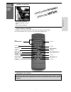
Narrow sensing field antenna
Terminal block
Push buttons +/–
Led
Adjustment for
vertical position
of antenna
Adjustment of
lateral position of
antenna
Planar antenna
wide original sensing field
Cover viewed
from inside
INTERNAL VIEW
INSTALLATION
TIPS
• The sensor must be firmly
fastened in order not to
vibrate
• The sensor must not have
any object likely to move
or vibrate in its sensing
field
• No fluorescent lighting in
the sensing field
• The sensor must not be
placed directly behind a
panel or any kind of
material


