Weider PRO 125 User Manual
Part No. 157745 J01967-C R0200A
Printed in China © 2000 ICON Health & Fitness, Inc.
To order replacement parts, simply call our Customer Service Department toll-free at 1-800-999-3756, Monday
through Friday, 6 a.m. until 6 p.m. Mountain Time (excluding holidays). To help us assist you, please be pre-
pared to give the following information when calling:
• The MODEL NUMBER of the product (WEBE03390)
• The NAME of the product (WEIDER
®
PRO 125 weight bench)
• The SERIAL NUMBER of the product (see the front cover of this manual)
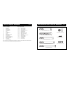
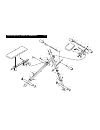
• The KEY NUMBER and DESCRIPTION of the desired part(s) (see the PART LIST and the EXPLODED
DRAWING in the center of this manual).
QUESTIONS?
As a manufacturer, we are com-
mitted to providing complete
customer satisfaction. If you
have questions, or if there are
missing parts, we will guarantee
complete satisfaction through
direct assistance from our factory.
TO AVOID UNNECESSARY
DELAYS, PLEASE CALL DIRECT
TO OUR TOLL-FREE CUSTOMER
HOT LINE. The trained techni-
cians on our customer hot line
will provide immediate assis-
tance, free of charge to you.
CUSTOMER HOT LINE:
1-800-999-3756
Mon.–Fri., 6 a.m.–6 p.m. MST
Model No. WEBE03390
Serial No.
Write the serial number in the space
above for reference.
CAUTION
Read all precautions and instruc-
tions in this manual before
using this equipment. Save this
manual for future reference.
Serial Number Decal
Ordering Replacement Parts
USER’S MANUAL
ICON Health & Fitness, Inc. (ICON), warrants this product to be free from defects in workmanship and mate-
rial, under normal use and service conditions, for a period of ninety (90) days from the date of purchase. This
warranty extends only to the original purchaser. ICON's obligation under this warranty is limited to replacing
or repairing, at ICON's option, the product at one of its authorized service centers. All products for which war-
ranty claim is made must be received by ICON at one of its authorized service centers with all freight and other
transportation charges prepaid, accompanied by sufficient proof of purchase. All returns must be pre-autho-
rized by ICON. This warranty does not extend to any product or damage to a product caused by or attribut-
able to freight damage, abuse, misuse, improper or abnormal usage or repairs not provided by an ICON
authorized service center, products used for commercial or rental purposes, or products used as store display
models. No other warranty beyond that specifically set forth above is authorized by ICON.
ICON is not responsible or liable for indirect, special or consequential damages arising out of or in connection
with the use or performance of the product or damages with respect to any economic loss, loss of property,
loss of revenues or profits, loss of enjoyment or use, costs of removal, installation or other consequential dam-
ages of whatsoever nature. Some states do not allow the exclusion or limitation of incidental or consequen-
tial damages. Accordingly, the above limitation may not apply to you.
The warranty extended hereunder is in lieu of any and all other warranties and any implied warranties of mer-
chantability or fitness for a particular purpose is limited in its scope and duration to the terms set forth herein.
Some states do not allow limitations on how long an implied warranty lasts. Accordingly, the above limitation
may not apply to you.
This warranty gives you specific legal rights. You may also have other rights which vary from state to state.
ICON HEALTH & FITNESS, INC., 1500 S. 1000 W., LOGAN, UT 84321-9813
Limited Warranty
Visit our website at
www.weiderfitness.com
new products, prizes,
fitness tips, and much more!


